

Mitsubishi FR-A520-0.4K-NA, FR-A520-55K-NA, FR-A520-22K-NA, FR-A520-37K-NA, FR-A520-7.5K-NA Instruction Manual
...
TRANSISTORIZED INVERTER
INSTRUCTION MANUAL
FR-A500
OUTLINE
Chapter 1
INSTALLATION
AND WIRING
Chapter 2
OPERATION
/CONTROL
Chapter 3
PARAMETERS
Chapter 4
PROTECTIVE
FUNCTIONS
Chapter 5
SPECIFICATIONS
Chapter 7
PRECAUTIONS FOR
MAINTENANCE AND
INSPECTION
Chapter 6
FR-A520-0.4K to 55K-NA
FR-A540-0.4K to 55K-NA,-EC
HIGH FUNCTION
&
LOW ACOUSTIC NOISE
FR-A500-NA,-EC
TRANSISTORIZED INVERTER
INSTRUCTION MANUAL
Thank you for choosing this Mitsubishi transistorized Inverter.
This instruction manual gives handling information and precautions for use of this equipment.
Incorrect handling might cause an unexpected fault. Before using the inverter, please read this manual carefully to use the
equipment to its optimum.
Please forward this manual to the end user.
This instruction manual uses the International System of Units (SI). The measuring units in the yard and pound system are
indicated in parentheses as reference values.
This section is specifically about safety matters
Do not attempt to install, operate, maintain or inspect the inverter until you have read through this instruction manual and
appended documents carefully and can use the equipment correctly.
Do not use the inverter until you have a full knowledge of the equipment, safety information and instructions.
In this instruction manual, the safety instruction levels are classified into "WARNING" and "CAUTION".
WARNING
CAUTION
Note that the level may lead to a serious consequence according to conditions. Please follow the instructions of both
levels because they are important to personnel safety.
CAUTION
Assumes that incorrect handling may cause hazardous conditions, resulting in death or severe
injury.
Assumes that incorrect handling may cause hazardous conditions, resulting in medium or
slight injury, or may cause physical damage only.
1. Electric Shock Prevention
WARNING
While power is on or when the inverter is running, do not open the front cover. You may get an electric shock.
Do not run the inverter with the front cover removed. Otherwise, you may access the exposed high-voltage terminals or the
charging part of the circuitry and get an electric shock.
Even if power is off, do not remove the front cover except for wiring or periodic inspection. You may access the charged inverter
circuits and get an electric shock.
Before starting wiring or inspection, check to make sure that the inverter power indicator lamp is off, wait for at least 10 minutes
after the power supply has been switched off, and check that there are no residual voltage using a tester or the like. The capacitor is
charged with high voltage for some time after power off and it is dangerous.
This inverter must be earthed (grounded). Earthing (grounding) must conform to the requirements of national and local safety
regulations and electrical code. (JIS, NEC section 250, IEC 536 class 1 and other applicable standards)
Any person who is involved in the wiring or inspection of this equipment should be fully competent to do the work.
Always install the inverter before wiring. Otherwise, you may get an electric shock or be injured.
Perform setting dial and key operations with dry hands to prevent an electric shock.
Do not subject the cables to scratches, excessive stress, heavy loads or pinching. Otherwise, you may get an electric shock.
Do not change the cooling fan while power is on. To do so will invite a hazardous condition.
2. Fire Prevention
CAUTION
Mount the inverter on an incombustible surface. Installing the inverter directly on or near a combustible surface could lead to a fire.
If the inverter has become faulty, switch off the inverter power. A continuous flow of large current could cause a fire.
When using a brake resistor, make up a sequence that will turn off power when an alarm signal is output. Otherwise, the brake
resistor may excessively overheat due to damage of the brake transistor and such, causing a fire.
Do not connect a resistor directly to the DC terminals P/+, N/-. This could cause a fire.
3. Injury Prevention
CAUTION
Apply only the voltage specified in the instruction manual to each terminal to prevent damage etc.
Ensure that the cables are connected to the correct terminals. Otherwise, damage etc. may occur.
Always make sure that polarity is correct to prevent damage etc.
While power is on and for some time after power-off, do not touch the inverter as it is hot and you may get burnt.
A-1
4. Additional Instructions
Also note the following points to prevent an accidental failure, injury, electric shock, etc.
(1) Transportation and installation
CAUTION
When carrying products, use correct lifting gear to prevent injury.
Do not stack the inverter boxes higher than the number recommended.
Ensure that installation position and material can withstand the weight of the inverter. Install according to the information in the
Instruction Manual.
Do not operate if the inverter is damaged or has parts missing.
Do not hold the inverter by the front cover; it may fall off.
Do not stand or rest heavy objects on the inverter.
Check the inverter mounting orientation is correct.
Prevent screws, wire fragments, conductive bodies, oil or other flammable substances from entering the inverter.
Do not drop the inverter, or subject it to impact.
Use the inverter under the following environmental conditions:
Ambient temperature
Ambient humidity 90%RH or less (non-condensing)
Storage temperature -20°C to +65°C* (-4°F to 149°F)
Ambience Indoors (free from corrosive gas, flammable gas, oil mist, dust and dirt)
Environment
Altitude, vibration
*Temperatures applicable for a short time, e.g. in transit.
(2) Wiring
-10°C to +50°C (14°F to 122°F) (non-freezing)
(-10°C to +40°C with totally ecclosed structure specification attachment (FR-A5CV))
(14°F to 104°F)
Maximum 1000m (3280.80 feet.) above sea level for standard operation.
After that derate by 3% for every extra 500m(1640.40 feet.) up to 2500m(8202.00 feet.)
(91%).
2
or less (conforming to JIS C 60068-2-6)
5.9 m/s
CAUTION
Do not fit capacitive equipment such as a power factor correction capacitor, surge suppressor or radio noise filter (option FR-BIF)
to the inverter output side.
The connection orientation of the output cables (terminals U, V, W) to the motor will affect the direction of rotation of the motor.
(3) Trial run
CAUTION
Check all parameters, and ensure that the machine will not be damaged by a sudden start-up.
(4) Operation
WARNING
When you have chosen the retry function, stay away from the equipment as it will restart suddenly after an alarm stop.
The [STOP] key is valid only when the appropriate function setting has been made. Prepare an emergency stop switch separately.
Make sure that the start signal is off before resetting the inverter alarm. A failure to do so may restart the motor suddenly.
The load used should be a three-phase induction motor only. Connection of any other electrical equipment to the inverter output
may damage the equipment.
Do not modify the equipment.
Do not perform parts removal which is not instructed in this manual. Doing so may lead to fault or damage of the inverter.
CAUTION
The electronic thermal relay function does not guarantee protection of the motor from overheating.
Do not use a magnetic contactor on the inverter input for frequent starting/stopping of the inverter.
Use a noise filter to reduce the effect of electromagnetic interference. Otherwise nearby electronic equipment may be affected.
Take measures to suppress harmonics. Otherwise power supply harmonics from the inverter may heat/damage the power capacitor
and generator.
When a 400V class motor is inverter-driven, please use an insulation-enhanced motor or measure taken to suppress surge
voltages. Surge voltages attributable to the wiring constants may occur at the motor terminals, deteriorating the insulation of the
motor.
When parameter clear or all clear is performed, each parameter returns to the factory setting. Re-set the required parameters
before starting operation.
The inverter can be easily set for high-speed operation. Before changing its setting, examine the performance of the motor and
machine.
In addition to the inverter's holding function, install a holding device to ensure safety.
Before running an inverter which had been stored for a long period, always perform inspection and test operation.
A-2
(5) Emergency stop
CAUTION
Provide a safety backup such as an emergency brake which will prevent the machine and equipment from hazardous conditions if
the inverter fails.
When the breaker on the inverter primary side trips, check for the wiring fault (short circuit), damage to internal parts of the inverter,
etc. Identify the cause of the trip, then remove the cause and power on the breaker.
When any protective function is activated, take the appropriate corrective action, then reset the inverter, and resume operation.
(6) Maintenance, inspection and parts replacement
CAUTION
Do not carry out a megger (insulation resistance) test on the control circuit of the inverter.
(7) Disposing of the inverter
CAUTION
Treat as industrial waste.
(8) General instructions
Many of the diagrams and drawings in this instruction manual show the inverter without a cover, or partially open. Never run
the inverter in this manner. Always replace the cover and follow this instruction manual when operating the inverter.
A-3

CONTENTS
CHAPTER 1 OUTLINE 1
1.1 Pre-Operation Information .................................................................................. 2
1.1.1 Precautions for operation ...................................................................................................................2
1.2 Basic Configuration............................................................................................. 3
1.2.1 Basic configuration.............................................................................................................................3
1.3 Structure ............................................................................................................... 4
1.3.1 Appearance and structure..................................................................................................................4
1.3.2 Removal and reinstallation of the front cover.....................................................................................5
1.3.3 Removal and reinstallation of the operation panel .............................................................................7
CHAPTER 2 INSTALLATION AND WIRING 9
2.1 Installation .......................................................................................................... 10
2.1.1 Instructions for installation................................................................................................................10
2.2 Wiring.................................................................................................................. 12
2.2.1 Terminal connection diagram...........................................................................................................12
2.2.2 Wiring of the main circuit..................................................................................................................15
2.2.3 Wiring of the control circuit...............................................................................................................21
2.2.4 Connection to the PU connector ......................................................................................................25
2.2.5 Connection of stand-alone option units............................................................................................28
2.2.6 Design information ...........................................................................................................................33
2.3 Other wiring........................................................................................................ 34
2.3.1 Power supply harmonics ..................................................................................................................34
2.3.2 Inverter-generated noises and their reduction techniques ...............................................................34
2.3.3 Leakage currents and countermeasures..........................................................................................37
2.3.4 Inverter-driven 400V class motor .....................................................................................................38
2.3.5 Peripheral devices............................................................................................................................39
2.3.6 Instructions for UL and cUL..............................................................................................................42
2.3.7 Instructions for compliance with the European Directives................................................................43
2.3.8 Earthing (EC version).......................................................................................................................45
CHAPTER 3 OPERATION/CONTROL 47
3.1 Pre-Operation Information ................................................................................ 48
3.1.1 Devices and parts to be prepared for operation...............................................................................48
3.1.2 Power on ..........................................................................................................................................50
3.2 Operation Panel ................................................................................................. 51
3.2.1 Names and functions of the operation panel (FR-DU04) .................................................................51
3.2.2 Monitor display changed by pressing the key .................................................................................52
3.2.3 Monitoring.........................................................................................................................................52
3.2.4 Frequency setting.............................................................................................................................52
3.2.5 Parameter setting method................................................................................................................53
3.2.6 Operation mode................................................................................................................................54
3.2.7 Help mode........................................................................................................................................54
3.2.8 Copy mode.......................................................................................................................................56
3.3 Operation ............................................................................................................ 57
3.3.1 Pre-operation checks .......................................................................................................................57
I

3.3.2 External operation mode (Operation using external input signals)...................................................58
3.3.3 PU operation mode
(Operation using the operation panel (FR-DU04)) ..........................................................................59
3.3.4 Combined operation mode
(Operation using the external input signals and PU)........................................................................60
CHAPTER 4 PARAMETERS 61
4.1 Parameter Lists ..................................................................................................62
4.1.1 Parameter lists .................................................................................................................................62
4.1.2 List of parameters classified by purpose of use ...............................................................................69
4.1.3 Parameters recommended to be set by the user .............................................................................70
4.2 Parameter Function Details .............................................................................. 71
4.2.1 Torque boost (Pr. 0, Pr. 46, Pr. 112)................................................................................................71
4.2.2 Output frequency range (Pr. 1, Pr. 2, Pr. 18) ...................................................................................72
4.2.3 Base frequency, base frequency voltage (Pr. 3, Pr. 19, Pr. 47, Pr. 113) .........................................73
4.2.4 Multi-speed operation (Pr. 4 to Pr. 6, Pr. 24 to Pr. 27, Pr. 232 to Pr. 239).......................................74
4.2.5 Acceleration/deceleration time (Pr. 7, Pr. 8, Pr. 20, Pr. 21, Pr. 44, Pr. 45, Pr. 110, Pr. 111)..........75
4.2.6 Electronic overcurrent protection (Pr. 9)...........................................................................................76
4.2.7 DC injection brake (Pr. 10 to Pr. 12) ................................................................................................77
4.2.8 Starting frequency (Pr. 13) ...............................................................................................................78
4.2.9 Load pattern selection (Pr. 14).........................................................................................................79
4.2.10 Jog operation (Pr. 15, Pr. 16)...........................................................................................................80
4.2.11 MRS input selection (Pr. 17) ............................................................................................................81
4.2.12 Stall prevention (Pr. 22, Pr. 23, Pr. 66, Pr. 148, Pr. 149, Pr. 154)....................................................82
4.2.13 Multi-speed input compensation (Pr. 28)..........................................................................................83
4.2.14 Acceleration/deceleration pattern (Pr. 29, Pr. 140 to Pr. 143)..........................................................84
4.2.15 Regenerative brake duty (Pr. 30, Pr. 70)..........................................................................................85
4.2.16 Frequency jump (Pr. 31 to Pr. 36)....................................................................................................86
4.2.17 Speed display (Pr. 37, Pr. 144) ........................................................................................................87
4.2.18 Up-to-frequency sensitivity (Pr. 41)..................................................................................................88
4.2.19 Output frequency detection (Pr. 42, Pr. 43, Pr. 50, Pr. 116) ............................................................88
4.2.20 Second/third stall prevention (Pr. 48, Pr. 49, Pr. 114, Pr. 115) ........................................................89
4.2.21 Monitor display/FM, AM terminal function selection (Pr. 52 to Pr. 54, Pr. 158)................................90
4.2.22 Monitoring reference (Pr. 55, Pr. 56)................................................................................................93
4.2.23 Automatic restart after instantaneous power failure (Pr. 57, Pr. 58, Pr. 162, Pr. 165, Pr. 611).......94
4.2.24 Remote setting function selection (Pr. 59) .......................................................................................96
4.2.25 Intelligent mode selection (Pr. 60)....................................................................................................98
4.2.26 Acceleration/deceleration reference current (Pr. 61 to Pr. 64) .......................................................100
4.2.27 Retry function (Pr. 65, Pr. 67 to Pr. 69) ..........................................................................................101
4.2.28 Applied motor (Pr. 71) ....................................................................................................................103
4.2.29 PWM carrier frequency (Pr. 72, Pr. 240)........................................................................................104
4.2.30 Voltage input (Pr. 73) .....................................................................................................................105
4.2.31 Input filter time constant (Pr. 74) ....................................................................................................106
4.2.32 Reset selection/disconnected PU detection/PU stop selection (Pr. 75).........................................106
4.2.33 Alarm code output selection (Pr. 76)..............................................................................................108
4.2.34 Parameter write disable selection (Pr. 77) .....................................................................................109
4.2.35 Reverse rotation prevention selection (Pr. 78) ...............................................................................110
4.2.36 Operation mode selection (Pr. 79) .................................................................................................111
4.2.37 Motor capacity/number of motor poles/speed control gain (Pr. 80, Pr. 81, Pr. 89) ........................114
4.2.38 Offline auto tuning function (Pr. 82 to Pr. 84, Pr. 90 to Pr. 94, Pr. 96) ...........................................115
4.2.39 Online auto tuning selection (Pr. 95)..............................................................................................123
Contents
II

4.2.40 V/F control frequency (voltage) (Pr. 100 to Pr. 109).......................................................................125
4.2.41 Computer link operation (Pr. 117 to Pr. 124, Pr. 342)....................................................................126
4.2.42 PID control (Pr. 128 to Pr. 134)......................................................................................................137
4.2.43 Commercial power supply-inverter switchover function (Pr. 135 to Pr. 139)..................................144
4.2.44 Output current detection function (Pr. 150, Pr. 151).......................................................................149
4.2.45 Zero current detection (Pr. 152, Pr. 153)........................................................................................150
4.2.46 RT signal activated condition selection (Pr. 155) ...........................................................................151
4.2.47 Stall prevention function and current limit function (Pr. 156)..........................................................151
4.2.48 OL signal output timer (Pr. 157) .....................................................................................................153
4.2.49 User group selection (Pr. 160, Pr. 173 to Pr. 176) .........................................................................154
4.2.50 Watt-hour meter clear/actual operation hour meter clear (Pr. 170, Pr. 171) ..................................155
4.2.51 Input terminal function selection (Pr. 180 to Pr. 186) .....................................................................155
4.2.52 Output terminal function selection (Pr. 190 to Pr. 195) ..................................................................158
4.2.53 User initial value setting (Pr. 199) ..................................................................................................160
4.2.54 Programmed operation function (Pr. 200 to Pr. 231) .....................................................................161
4.2.55 Cooling fan operation selection (Pr. 244).......................................................................................165
4.2.56 Stop selection (Pr. 250)..................................................................................................................166
4.2.57 Output phase failure protection selection (Pr. 251)........................................................................167
4.2.58 Override bias/gain (Pr. 252, Pr. 253)..............................................................................................167
4.2.59 Power failure-time deceleration-to-stop function (Pr. 261 to Pr. 266) ............................................168
4.2.60 Stop-on-contact, load torque high-speed frequency selection (Pr. 270) ........................................169
4.2.61 High-speed frequency control (Pr. 271 to Pr. 274).........................................................................170
4.2.62 Stop-on-contact control function (Pr. 275, Pr. 276)........................................................................174
4.2.63 Brake sequence function (Pr. 278 to Pr. 285) ................................................................................177
4.2.64 Droop control (Pr. 286, Pr. 287) .....................................................................................................181
4.2.65 Capacitor life alarm (Pr. 503, Pr. 504)............................................................................................182
4.2.66 FM / AM terminal calibration (Pr. 900, Pr. 901).............................................................................183
4.2.67 Frequency setting voltage (current) bias and gain (Pr. 902 to Pr. 905)..........................................185
4.2.68 PU buzzer control (Pr. 990)............................................................................................................190
CHAPTER 5 PROTECTIVE FUNCTIONS 191
5.1 Errors (Alarms)................................................................................................ 192
5.1.1 Error (alarm) definitions..................................................................................................................192
5.1.2 To know the operating status at the occurrence of an alarm .........................................................201
5.1.3 Correspondences between digital and actual characters...............................................................201
5.1.4 Alarm code output ..........................................................................................................................202
5.1.5 Resetting the inverter .....................................................................................................................202
5.2 Troubleshooting...............................................................................................203
5.2.1 Motor remains stopped...................................................................................................................203
5.2.2 Motor rotates in opposite direction .................................................................................................203
5.2.3 Speed greatly differs from the setting.............................................................................................203
5.2.4 Acceleration/deceleration is not smooth.........................................................................................203
5.2.5 Motor current is large .....................................................................................................................203
5.2.6 Speed does not increase................................................................................................................204
5.2.7 Speed varies during operation .......................................................................................................204
5.2.8 Operation mode is not changed properly .......................................................................................204
5.2.9 Operation panel (FR-DU04) display is not provided.......................................................................204
5.2.10 POWER lamp is not lit....................................................................................................................204
5.2.11 Parameter write cannot be performed............................................................................................204
III

CHAPTER 6 PRECAUTIONS FOR MAINTENANCE AND INSPECTION 205
6.1 Precautions for maintenance and inspection ............................................... 206
6.1.1 Precautions for maintenance and inspection .................................................................................206
6.1.2 Check items....................................................................................................................................206
6.1.3 Periodic inspection .........................................................................................................................206
6.1.4 Insulation resistance test using megger.........................................................................................207
6.1.5 Pressure test ..................................................................................................................................207
6.1.6 Daily and periodic inspection..........................................................................................................207
6.1.7 Replacement of parts .....................................................................................................................210
6.1.8 Inverter replacement ......................................................................................................................211
6.1.9 Measurement of main circuit voltages, currents and powers .........................................................212
CHAPTER 7 SPECIFICATIONS 215
7.1 Standard Specifications.................................................................................. 216
7.1.1 Model specifications.......................................................................................................................216
7.1.2 Common specifications ..................................................................................................................218
7.1.3 Outline dimension drawings ...........................................................................................................220
CHAPTER 8 OPTIONS 225
Contents
8.1 Option List ........................................................................................................ 226
8.1.1 Stand-alone options .......................................................................................................................226
8.1.2 Plug-in dedicated options...............................................................................................................228
APPENDICES 239
Appendix1 Instruction Code List............................................................................ 240
Appendix2 Operating the Inverter Using a Single-Phase Power Supply ............. 247
IV


CHAPTER 1
OUTLINE
This chapter gives information on the basic "outline" of this
product.
Always read the instructions in this chapter before using the
equipment.
1.1 Pre-Operation Information ....................................... 2
1.2 Basic Configuration ................................................. 3
1.3 Structure.................................................................. 4
<Abbreviations>
•DU
Operation panel (FR-DU04)
•PU
Operation panel (FR-DU04) and parameter unit (FR-PU04)
•Inverter
Mitsubishi transistorized inverter FR-A500 series
•Pr.
Parameter number
• PU operation
Operation using the PU (FR-DU04/FR-PU04)
• External operation
Operation using the control circuit signals
• Combined operation
Operation using both the PU (FR-DU04/FR-PU04) and
external operation
•FR-A200E
Mitsubishi transistorized inverter FR-A200 series
<EXCELLENT> series
Chapter 1
Chapter 2
Chapter 3
Chapter 4
Chapter 5
Chapter 6
Chapter 7
Chapter 8
1
OUTLINE
e
1.1 Pre-Operation Information
1.1.1 Precautions for operation
Incorrect handling might cause the inverter to operate improperly, its life to be reduced considerably, or at the
worst, the inverter to be damaged. Handle the inverter properly in accordance with the information in each
section as well as the precautions and instructions of this manual to use it correctly.
This manual is written for the FR-A500 series transistorized inverters.
For handling information on the parameter unit (FR-PU04), plug-in options, stand-alone options, etc., refer to
the corresponding manuals.
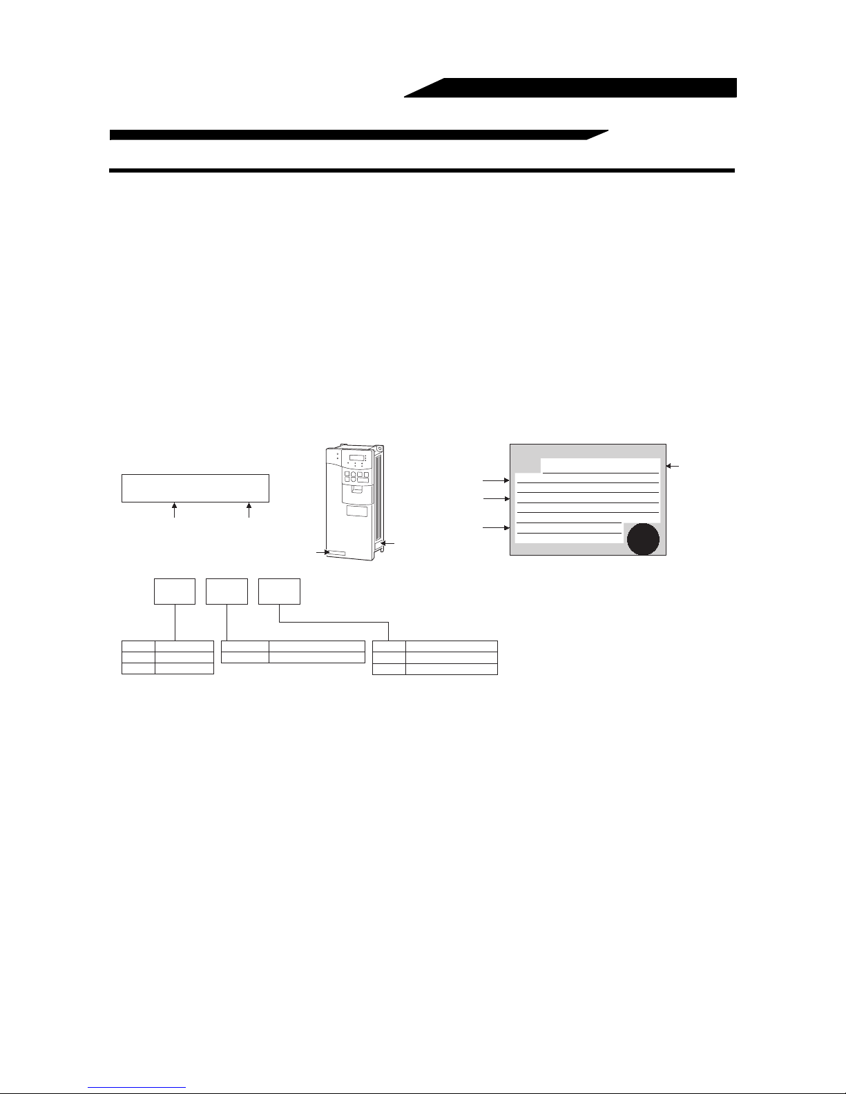
(1) Unpacking and product check
Unpack the inverter and check the capacity plate on the front cover and the rating plate on the inverter side
face to ensure that the product agrees with your order and the inverter is intact.
1) Inverter type
Capacity plate
FR-A520-0.4K
Input rating
Output rating
MITSUBISHI
MODEL
INPUT :
OUTPUT :
Rating plate
FR-A520-0.4K
XXXXX
XXXXX
INVERTER
Inverter typ
Inverter type
FR- A520 - 0.4K
Voltage Class
Symbol
A520
200V class
A540
400V class
Serial number
Capacity plate
-
Applicable Motor Capacity
Symbol
0.4K to 55K Indicates capacity in "kW".
Serial number
Rating plate
Symbol
NA U.S. specifications
EC European specifications
Specifications
SERIAL :
PASSED
2) Accessory
Instruction manual
If you have found any discrepancy, damage, etc., please contact your sales representative.
(2) Preparations of instruments and parts required for operation
Instruments and parts to be prepared depend on how the inverter is operated. Prepare equipment and parts
as necessary. (Refer to page 48.)
(3) Installation
To operate the inverter with high performance for a long time, install the inverter in a proper place, in the
correct direction, and with proper clearances. (Refer to page 10.)
(4) Wiring
Connect the power supply, motor and operation signals (control signals) to the terminal block. Note that
incorrect connection may damage the inverter and peripheral devices. (Refer to page 12.)
2
OUTLINE
A
1.2 Basic Configuration
1.2.1 Basic configuration
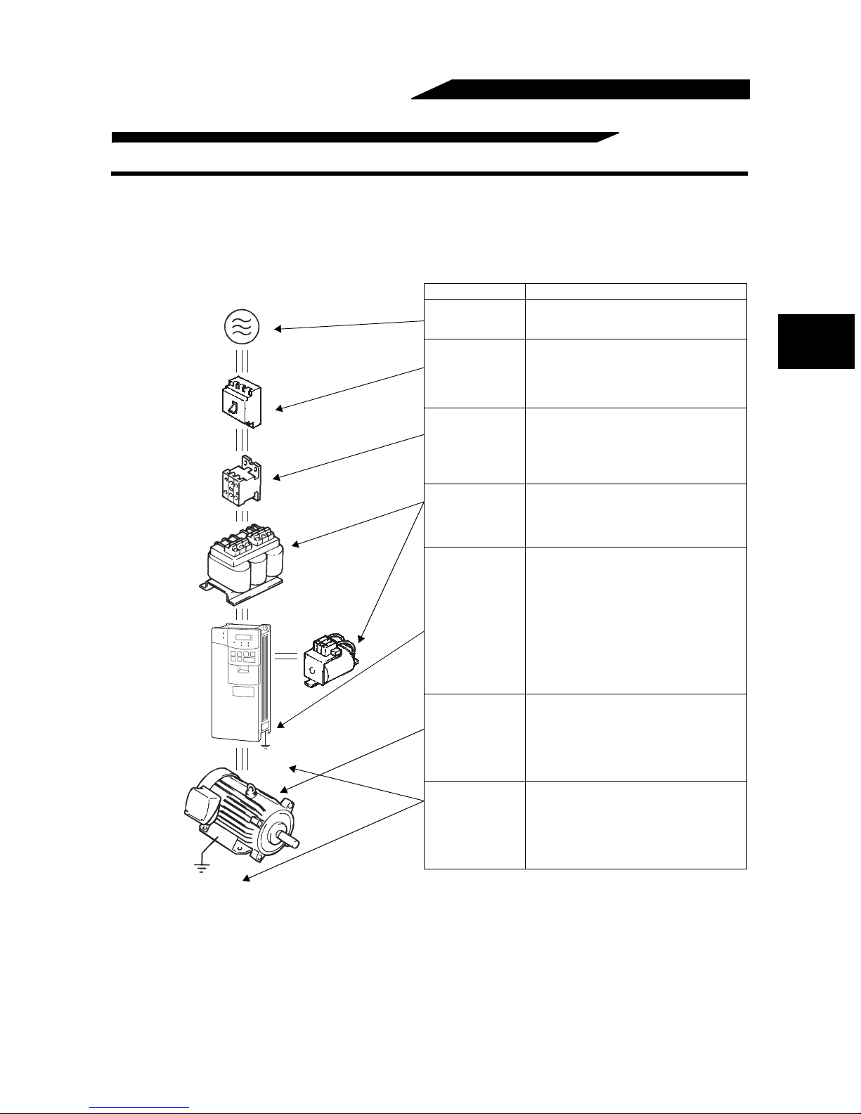
The following devices are required to operate the inverter. Proper peripheral devices must be selected and correct
connections made to ensure proper operation. Incorrect system configuration and connections can cause the
inverter to operate improperly, its life to be reduced considerably, and in the worst case, the inverter to be damaged.
Please handle the inverter properly in accordance with the information in each section as well as the precautions and
instructions of this manual. (For connections of the peripheral devices, refer to the corresponding manuals.)
Name Description
Power supply
Earth leakage
circuit breaker
(ELB) or moulded
(MCCB)
or
(ELB)
(MC)
C reactor
(FR-BAL)
DC reactor
(FR-BEL)
Earth
(Ground)
Earth
(Ground)
case circuit
breaker (MCCB)
Magnetic
contactor
Reactors
Inverter
Devices
connected to the
output
Earth (Ground)
Use the power supply within the permissible
power supply specifications of the inverter.
(Refer to page 216.)
1
The breaker should be selected with care
since a large inrush current flows in the
inverter at power on. (Refer to page 39.)
Install the magnetic contactor to ensure
safety. (Refer to page 41)
Do not use this magnetic contactor to start
and stop the inverter. Doing so will cause the
inverter life to be shorter.
(Refer to page 39.)
The reactors must be used when the power
factor is to be improved or the inverter is
installed near a large power supply system
(1000kVA or more and wiring distance within
10m (32.81 feet)). Make selection carefully.
• The life of the inverter is influenced by
ambient temperature. The ambient
temperature should be as low as possible
within the permissible range.
This must be noted especially when the
inverter is installed in an enclosure.
(Refer to page 10.)
• Wrong wiring might lead to damage of the
inverter. The control signal lines must be
kept fully away from the main circuit to
protect them from noise. (Refer to page
12.)
• Do not install a power factor correction
capacitor, surge suppressor or radio noise
filter on the output side.
• When installing a moulded case circuit
breaker (MCCB) on the output side of the
inverter, contact each manufacturer for
selection of the moulded case circuit breaker.
To prevent an electric shock, always earth
(ground) the motor and inverter.
For reduction of induction noise from the
power line of the inverter, it is recommended
to wire the earth (ground) cable by returning
it to the earth (ground) terminal of the
inverter. (Refer to page 36.)
3

1.3 Structure
1.3.1 Appearance and structure
OUTLINE
(1) Front view
POWER lamp
ALARM lamp
Operation panel (FR-DU04)
Brake resistor* (Fitted to the back)
Accessory cover
Wiring port cover for option
(DATA PORT)
Front cover
Rating plate
Capacity plate
(2) Without front cover
PU connector
(Provided with modular jack type relay connector)
(For use with RS-485 cable communication)
Modular jack type relay connector compartment
Inboard option mounting positions
Control circuit terminal block
Main circuit terminal block
Wiring cover
*7.5K or less inverters are equipped with an
inboard brake resistor.
Note: The "EC" version of the FR-A500 uses pheonix type connectors for the control circuit terminal block.
Lamp indication
Power lamp . . . . . . . . . . . . . . . .Lights when power is supplied to the control circuit (R1, S1).
Alarm lamp . . . . . . . . . . . . . . . .Lights when the inverter is in the alarm status (major faults).
4
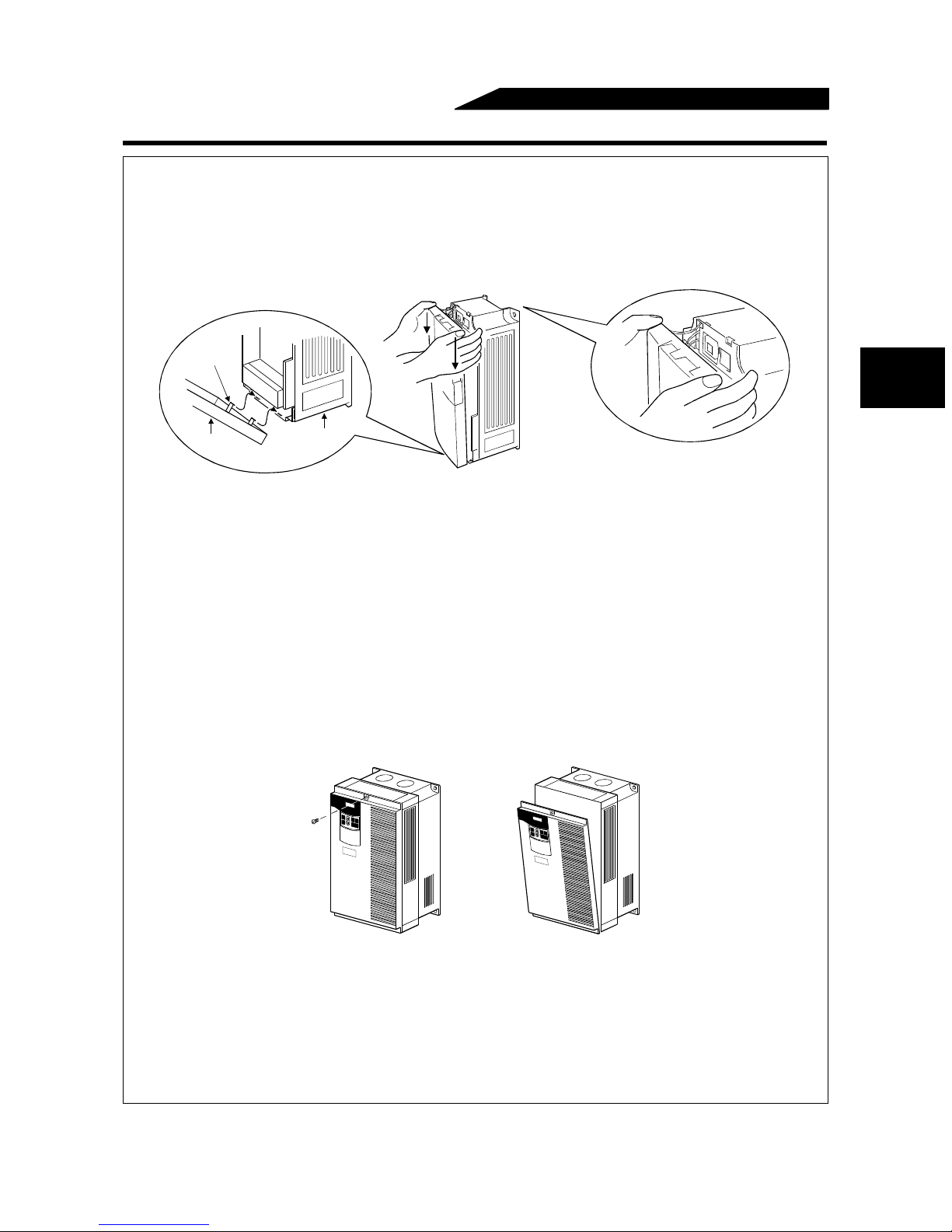
1.3.2 Removal and reinstallation of the front cover
FR-A520-0.4K to 11K-NA, FR-A540-0.4K to 7.5K-NA/-EC
• Removal
1) Hold both sides of the front cover top and push the front cover down.
2) Hold down the front cover and pull it toward you to remove.
(The front cover may be removed with the PU (FR-DU04/FR-PU04) on.)
hook
OUTLINE
1
Front cover
• Reinstallation
1) Insert the hooks at the bottom of the front cover into the sockets of the inverter.
2) Using the hooks as supports, securely press the front cover against the inverter.
Note:When the operation panel is fitted to the removed front cover, reinstall the front cover after
removing the operation panel.
Inverter
FR-A520-15K to 22K-NA, FR-A540-11K to 22K-NA/-EC
• Removal
1) Remove the installation screw at top of the front cover.
2) Hold both ends of the front cover top.
3) Pull the front cover toward you to remove.
(The front cover may be removed with the PU (FR-DU04/FR-PU04) on.)
• Reinstallation
1) Insert the hooks at the front cover bottom into the sockets of the inverter.
2) Using the hooks as supports, securely press the front cover against the inverter.
3) Fix the front cover with the top screw.
Note:When the operation panel is fitted to the removed front cover, reinstall the front cover after
removing the operation panel.
5
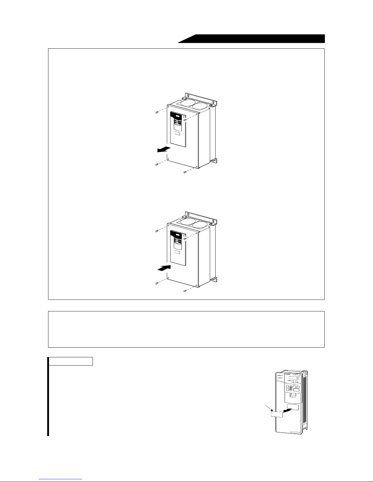
FR-A520-30K to 55K-NA, FR-A540-30K to 55K-NA/-EC
• Removal
1) Remove installation screws on the front cover.
• Reinstallation
1) Fix the front cover with the installation screws.
OUTLINE
Note: 1. Fully make sure that the front cover has been reinstalled securely.
2. The same serial number is printed on the capacity plate of the front cover and the rating plate of
the inverter. Before reinstalling the front cover, check the serial number to ensure that the cover
removed is reinstalled to the inverter from where it was removed.
REMARKS
• Removal of the wiring port cover for option (DATA PORT)
Push the option wiring port cover for option (DATA PORT) from
the back of the front cover to remove before fitting the
communication option.
Wiring port cover
for option
(DATA PORT)
6
OUTLINE
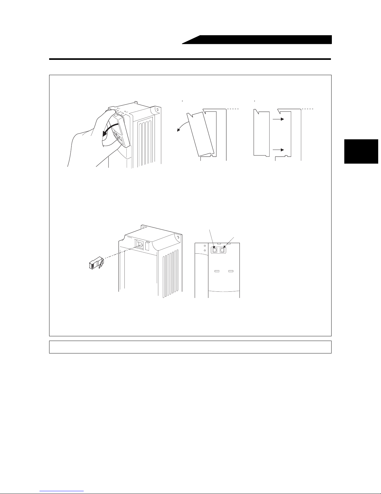
1.3.3 Removal and reinstallation of the operation panel
To ensure safety, remove and reinstall the operation panel after powering off.
• Removal
Hold down the top button of the operation panel and pull the operation panel toward you to remove.
Removal
Reinstallation
When reinstalling the operation panel, insert it straight and reinstall it securely.
• Reinstallation using the connection cable
1) Remove the operation panel.
2) Disconnect the modular jack type relay connector. (Place the disconnected modular jack type relay
connector in the modular jack type relay connector compartment.)
Modular jack type relay connector
Modular jack type relay connector compartment
1
3) Securely plug one end of the connection cable into the PU connector (modular jack type relay
connector) of the inverter and the other end into the operation panel. (Refer to page 25 for the
connection cable.)
Note: Install the operation panel only when the front cover is on the inverter.
7

MEMO
8

CHAPTER 2
INSTALLATION AND WIRING
This chapter explains the basic "installation and wiring" for use
of this product.
Always read the instructions and other information before using
the equipment.
2.1 Installation .............................................................10
2.2 Wiring ....................................................................12
2.3 Other wiring ...........................................................34
Chapter 1
Chapter 2
Chapter 3
Chapter 4
Chapter 5
Chapter 6
Chapter 7
Chapter 8
9
INSTALLATION AND WIRING
2.1 Installation
2.1.1 Instructions for installation
1) Handle the unit carefully.
The inverter uses plastic parts. Handle it gently to protect it from damage. Also, hold the unit with even
strength and do not apply too much strength to the front cover alone.
2) Install the inverter in a place where it is immune to vibration. (5.9 m/s
Also note the cart, press, etc.
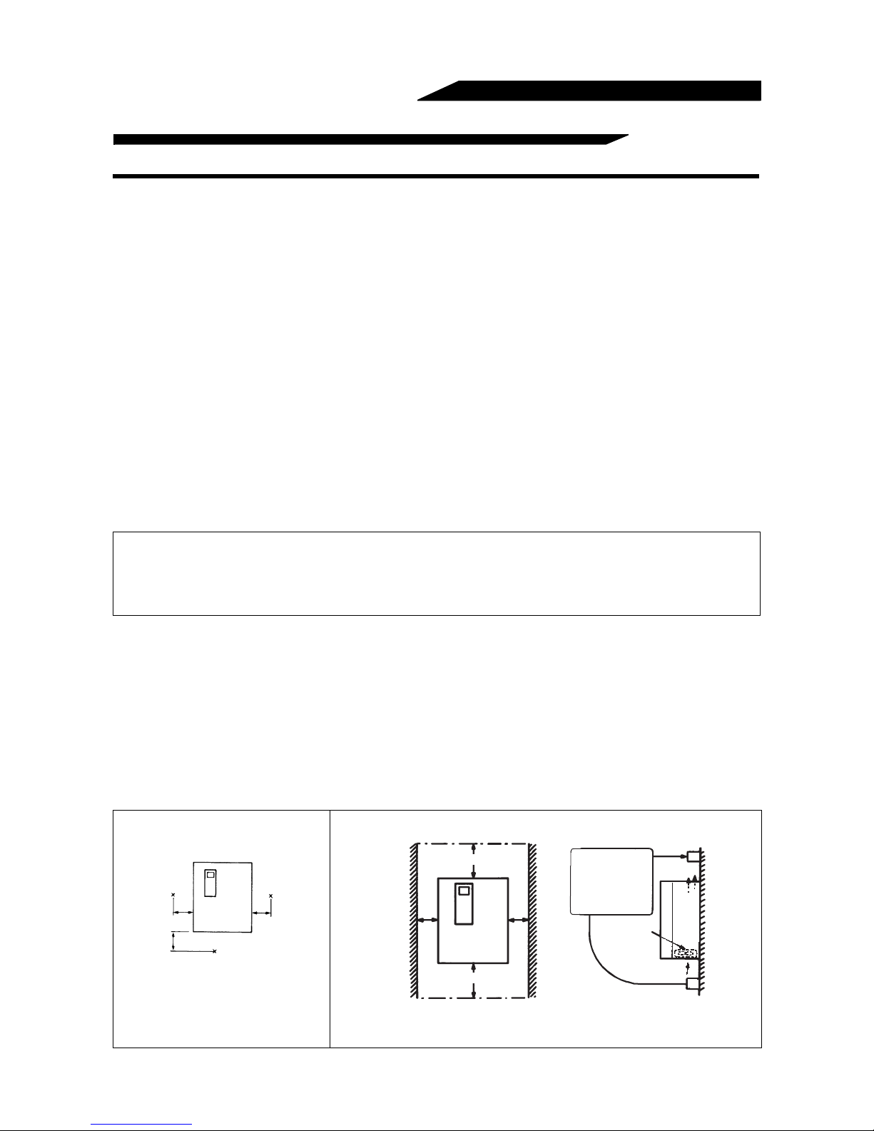
3) Note on ambient temperature
The life of the inverter is under great influence of ambient temperature. In the place of installation, ambient
temperature must be within the permissible range (-10
°C to +50°C (14°F to 122°F)). Check that the
ambient temperature is within that range in the positions shown in figure 3).
4) Install the inverter on a non-combustible surface.
The inverter will be very hot (maximum about 150
°C (302°F)). Install it on a non-combustible surface (e.g.
metal). Also leave sufficient clearances around the inverter.
5) Avoid high temperature and high humidity.
Avoid direct sunlight and places of high temperature and high humidity.
6) The amount of heat generated in an enclosure can be reduced considerably by placing the heatsink
outside the enclosure.
2
or less)
Note: 1. Use the option (FR-A5CN) for installation. The mounting area should be cut to the panel
cutting dimensions.
2. The cooling section outside the enclosure has the cooling fan. Do not use the inverter in any
environment where it is exposed to waterdrops, oil mist, dust, etc.
7) Avoid places where the inverter is exposed to oil mist, flammable gases, fluff, dust, dirt etc.
Install the inverter in a clean place or inside a "totally enclosed" panel, which does not accept any
suspended matter.
8) Note the cooling method when the inverter is installed in an enclosure.
When two or more inverters are installed or a ventilation fan is mounted in an enclosure, the inverters and
ventilation fan must be installed in proper positions with extreme care taken to keep the ambient
temperatures of the inverters below the permissible value. If they are installed in improper positions, the
ambient temperatures of the inverters will rise and ventilation effect will be reduced.
9) Install the inverter securely in the vertical direction with screws or bolts.
3) Note on ambient temperature 4) Clearances around the inverter
5cm
(1.97 inches)
5cm
(1.97 inches )
Measurement
position
Measurement
position
5cm
(1.97 inches)
10cm (3.94 inches)
or more
5cm (1.97 inches)
or more *
10cm (3.94 inches)
or more
5cm (1.97 inches)
or more *
Leave sufficient
clearances above
and under the
inverter to ensure
adequate ventilation.
Cooling fan built
in the inverter
Cooling air
*: 1cm (0.39 inches) or more for model 3.7K or less
These clearances are also necessary for changing
the cooling fan.
10
(
The
2.2K or more for 400V cl ass are
provided with a cooling fan.)
8) For installation in an enclosure
INSTALLATION AND WIRING
Ventilation fan
(Correct example)
Inverter Inverter
(Incorrect example)
Position of Ventilation Fan
Inverter
Built-in cooling fan
(Correct example)
Inverter
Accommodation of two or more inverters
Inverter
Inverter
(Incorrect example)
9) Vertical mounting
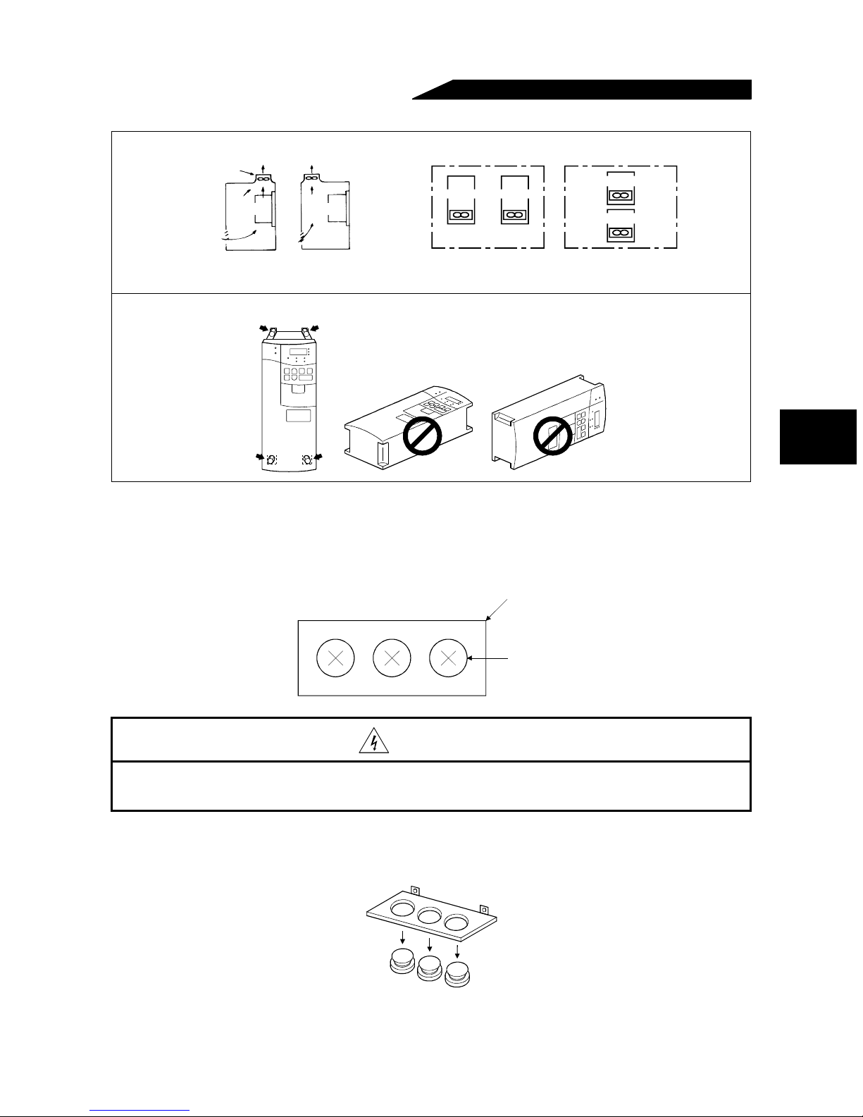
(1) Wiring cover and handling (22K or less)
1) When cable conduits are not connected
Cut the protective bushes of the wiring cover with nippers or a cutter before running the cables.
2
Wiring cover
Protective bush
WARNING
Do not remove the protective bushes. Otherwise, the cable sheathes may be scratched by
the wiring cover edges, resulting in a short circuit or earth (ground) fault.
2) When cable conduits are connected
Remove the corresponding protective bushes and connect the cable conduits.
11
2.2 Wiring
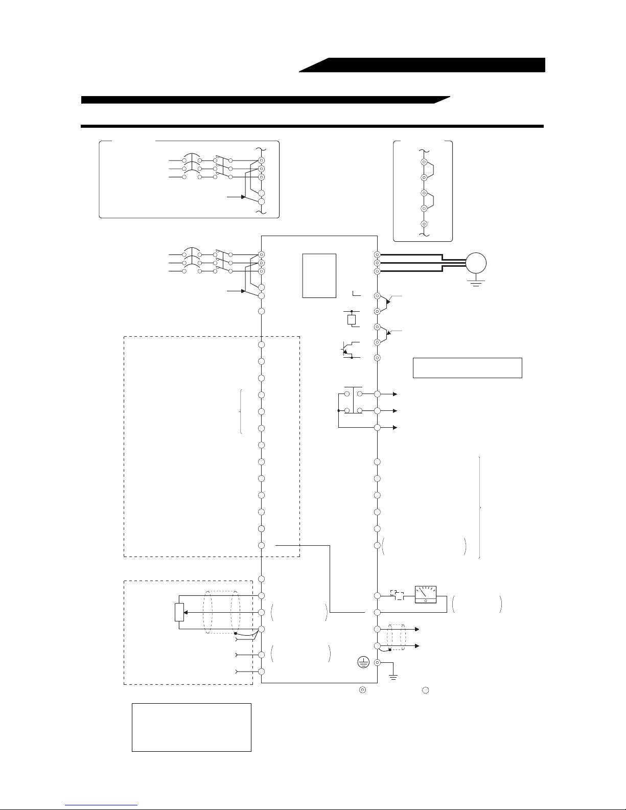
2.2.1 Terminal connection diagram
EC version
3-phase AC power supply
MCCB
Jumper
L
1
L
2
L
3
L
11
L
21
INSTALLATION AND WIRING
EC version
P1
+
PX
PR
–
MCCB
3-phase AC power supply
Jumper
24VDC power output and external transistor common
(Contact input common for source logic)
Forward rotation start
Reverse rotation start
Start self-holding selection
Multi-speed selection
Second acceleration/deceleration time selection
Current input selection
Selection of automatic restart
after instantaneous power failure
(Contact input common for sink logic)
Control input signals (no voltage input allowed)
Frequency setting signals (analog)
Frequency setting
potentiometer
1/2W1k
3
2
W
1
Common
Auxiliary input
Current input
High
Middle
Low
Jog mode
Output stop
Reset
1
R/L
S/L2
T/L3
R1/L11
S1/L21
PC
STF
STR
STOP
RH
RM
RL
JOG
RT
MRS
RES
AU
CS
SD
10E(+10V)
10(+5V)
0 to 5VDC
2
0 to 10VDC
5
(Analog common)
0 to ± 5VDC
1
0 to ±10VDC
4 (4 to 20mADC)
PU
connector
Selected
Selected
U
V
W
P1
P/+
(Note)
R
PX
(Note)
PR
N/–
A
B
C
RUN
SU
IPF
OL
FU
SE
FM
SD
5
Main circuit terminal Control circuit terminal
Jumper
Remove this jumper when using FR-BEL.
Jumper
Remove this jumper when using FR-ABR.
Note: Terminals PR, PX are provided for
0.4K to 7.5K.
Alarm output
Running
Up to frequency
Instantaneous power failure
Overload
Frequency detection
Open collector output common
Common to sink and source
Meter
(e.g. frequency meter)
+-
Calibration
resistor*
(+)AM
Analog signal output
(0 to 10VDC)
(-)
Earth
(Ground)
Motor
IM
(Ground)
Open collector
outputs
Moving-coil type
1mA full-scale
Earth
When using current input
for frequency setting
signal, turn the AU signal
on.
* Not needed when the operation panel (FR-DU04) or
parameter unit (FR-PU04) is used for calibration. Used when
calibration must be made near the frequency meter for such a
reason as a remote frequency meter. However, the frequency
meter needle may not deflect to full-scale if the calibration
resistor is connected. In this case, use this resistor and the
operation panel or parameter unit together to make calibration.
12

INSTALLATION AND WIRING
(1) Description of main circuit terminals
Symbol Terminal Name Description
1>, S<L2>,
R<L
3>
T<L
U, V, W Inverter output Connect a three-phase squirrel-cage motor.
11>,
R1<L
21>
S1<L
P/+, PR
P/+, N Brake unit connection
P/+, P1
PR, PX
AC power input
Power supply for control
circuit
Brake resistor
connection
Power factor improving
DC reactor connection
Built-in brake circuit
connection
Earth (Ground) For earthing (grounding) the inverter chassis. Must be earthed (grounded).
Connect to the commercial power supply. Keep these terminals open when using the high
power factor converter (FR-HC) and power regeneration common converter (FR-CV).
Connected to the AC power supply terminals R/L
and alarm output or when using the high power factor converter (FR-HC) or power
regeneration common converter (FR-CV), remove the jumpers from terminals R/L
11 and S/L2-S1/L21 and apply external power to these terminals.
L
Disconnect the jumper from terminals PR-PX and connect the optional brake resistor
(FR-ABR) across terminals P/+-PR.
Connect the optional FR-BU brake unit, power regeneration converter (FR-RC), high
power factor converter (FR-HC) or power regeneration common converter (FR-CV).
Disconnect the jumper from terminals P/+-P1 and connect the optional power factor
improving reactor (FR-BEL).
When the jumper is connected across terminals PX-PR (factory setting),
the built-in brake circuit is valid.
(Provided for 7.5K or less.)
1 and S/L2. To retain the alarm display
1-R1/
*Note:<>Terminal names in parentheses are those of the EC version.
(2) Description of control circuit terminals
Type Symbol Terminal Name Description
Turn on the STF signal to start forward rotation and turn it off to
STF Forward rotation start
STR Reverse rotation start
STOP
RH, RM, RL Multi-speed selection
JOG JOG mode selection
RT
MRS Output stop
Input signals
RES Reset
Contacts, e.g. start (STF), stop (STOP) etc.
AU Current input selection
CS
SD
PC
Start self-holding
selection
Second acceleration/
deceleration time
selection
Automatic restart after
instantaneous power
failure selection
Contact input
common (sink)
24VDC power and
external transistor
common
Contact input
common (source)
stop. Acts as a programmed operation start signal in the
programmed operation mode. (Turn on to start and turn off to
stop.)
Turn on the STR signal to start reverse rotation and turn it off to
stop.
Turn on the STOP signal to select the self-holding of the start signal.
Use the RH, RM and RL signals as appropriate to select multiple
speeds.
Turn on the JOG signal to select jog operation (factory setting).
Jog operation can be performed with the start signal (STF or
STR).
Turn on the RT signal to select the second acceleration/
deceleration time. When the second functions such as "second
torque boost" and "second V/F (base frequency)" functions have
been set, these functions can also be selected by turning on the
RT signal.
Turn on the MRS signal (20ms or longer) to stop the inverter output.
Used to shut off the inverter output to bring the motor to a stop by the magnetic
brake.
Used to reset alarm output provided when protective function is activated. Turn on the
RES signal for more than 0.1s, then turn it off. Factory setting is reset always
enabled. By setting Pr. 75, reset can be set to enabled only at an inverter alarm
occurrence.
Recover about 1s after reset is cancelled.
Only when the AU signal is turned on, the inverter can be
operated with the 4-20mADC frequency setting signal.
Turning on the AU signal makes the voltage input invalid.
With the CS signal on, restart can be made automatically when
the power is restored after an instantaneous power failure. Note
that this operation requires restart parameters to be set. When
the inverter is shipped from the factory, it is set to disallow restart.
Common to the contact input terminals and terminal FM. Common output terminal for
24VDC 0.1A power (PC terminal).
When transistor output (open collector output), such as a programmable controller, is
connected, connect the external power supply common for transistor output to this
terminal to prevent a fault caused by undesirable current. This terminal can be used
as a 24VDC, 0.1A power output. When source logic has been selected, this terminal
serves as a contact input common.
13
2
When the STF
and STR signals
are turned on
simultaneously,
the stop command
is given.
Input terminal
function selection
(Pr. 180 to
Pr. 186) change
terminal
functions.
Input terminal
function selection
(Pr. 180 to
Pr. 186) change
terminal
functions.

INSTALLATION AND WIRING
Type Symbol Terminal Name Description
Analog
Frequency setting
Contact
Open collector
Output signals
Pulse
Analog
10E
10
2
4
1
5
A, B, C Alarm output
RUN Inverter running
SU Up to frequency
OL Overload alarm
IPF
FU Frequency detection
SE
FM For meter
AM Analog signal output
Frequency setting
power supply
Frequency setting
(voltage)
Frequency setting
(current)
Auxiliary frequency
setting
Frequency setting
input common
Instantaneous power
failure
Open collector output
common
10VDC, permissible load
current 10mA
5VDC, permissible load current
10mA
By entering 0 to 5VDC (0 to 10VDC), the maximum output frequency is reached at
5V (or 10V) and I/O are proportional. Switch between input 0 to 5VDC (factory
setting) and 0 to 10VDC from the operation panel. Input resistance 10kΩ. Maximum
permissible voltage 20V.
By entering 4 to 20mADC, the maximum output frequency is reached at 20mA and I/
O are proportional. This input signal is valid only when the AU signal is on. (Voltage
input is made invalid) Input resistance approximately 250Ω. Maximum permissible
current 30mA.
By entering 0 to ±5VDC or 0 to ±10VDC, this signal is added to the frequency setting
signal of terminal 2 or 4. Switch between input 0 to ±5VDC and 0 to ±10VDC (factory
setting) from the operation panel. Input resistance 10kΩ. Maximum permissible
voltage ±20V.
Common to the frequency setting signal (terminal 2, 1 or 4) and analog output
terminal AM. Do not earth (ground).
1 contact output indicating that the output has been stopped by
the inverter protective function activated.
230VAC 0.3A, 30VDC 0.3A. Alarm: discontinuity across B-C
(continuity across A-C), normal: continuity across B-C
(discontinuity across A-C).
Switched low when the inverter output frequency is equal to or
higher than the starting frequency (factory set to 0.5Hz, variable).
Switched high during stop or DC injection brake operation (*2).
Permissible load 24VDC 0.1A. (A voltage drop is 3.4V maximum
when the signal is on.)
Switched low when the output frequency has reached within
±10% of the set frequency (factory setting, variable). Switched
high during acceleration, deceleration or stop (*2). Permissible
load 24VDC 0.1A.
Switched low when the stall prevention function has caused stall
prevention to be activated. Switched high when stall prevention is
reset (*2). Permissible load 24VDC 0.1A.
Switched low when instantaneous power failure or undervoltage
protection is activated (*2). Permissible load 24VDC 0.1A.
Switched low when the output frequency has reached or
exceeded the detection frequency set as appropriate. Switched
high when the output frequency is below the detection frequency
(*2). Permissible load 24VDC 0.1A
Common to the RUN, SU, OL, IPF and FU terminals.
One selected from 16
monitoring items, such as
output frequency, is output. (*3)
The output signal is
proportional to the magnitude
of each monitoring item.
When the frequency setting potentiometer is
connected in the factory-set state, connect it to
terminal 10.
When it is connected to terminal 10E, change the
input specifications of terminal 2.
Factory setting of output item:
Frequency permissible load current 2mA
1440 pulses/s at 60Hz
Factory setting of output item:
Frequency output signal 0 to 10VDC
Permissible load current 1mA
Output terminal
function selection
(Pr. 190 to
Pr. 195) change
terminal
functions.
PU connector
RS-485
Communication
*1: Terminals PR and PX are provided for the FR-A520-0.4K to 7.5K, FR-A540-0.4K to 7.5K.
*2: Low indicates that the open collector outputting transistor is on (conducts).
High indicates that the transistor is off (does not conduct).
*3: Not output while the inverter is reset.
With the operation panel connector, communication can be made through RS-485.
• Conforming standard : Standard RS-485
• Transmission format : Multi-drop link
• Communication speed : Maximum 19200 bps
• Overall length : 500m (1640.40 feet.)
14
INSTALLATION AND WIRING
)
2.2.2 Wiring of the main circuit
(1) Wiring instructions
1) Crimping terminals with insulation sleeves are recommended for use with the power and motor cables.
2) Cut the protective bushes of the wiring cover when running the cables. (22K or less)
3) Power must not be applied to the output terminals (U, V, W) of the inverter. Otherwise the inverter will be
damaged.
4) After wiring, wire off-cuts must not be left in the inverter.
Wire off-cuts can cause an alarm, failure or malfunction. Always keep the inverter clean.
When drilling mounting holes in a control box etc., exercise care to prevent chips and other foreign
matter from entering the inverter.
5) Use cables of the recommended size for wiring to make the voltage drop 2% or less.
If the wiring distance is long between the inverter and motor, a main circuit cable voltage drop will cause
the motor torque to decrease especially at the output of a low frequency. (A selection example for the
wiring length of 20m (65.62 feet) is shown on page 19.)
6) The overall wiring length should be 500m (1640.40 feet) maximum.
Especially for long distance wiring, the overcurrent protection may be misactivated or the devices
connected to the output side may misoperate or become faulty under the influence of a charging current
due to the stray capacitance of the wiring. Therefore, the maximum overall wiring length should be as
indicated in the following table. (When two or more motors are connected to the inverter, the total wiring
length should be within the indicated value.)
2
Inverter Capacity 0.4K 0.75K 1.5K or more
Non-low acoustic noise mode 300m (984.24 feet) 500m (1640.40 feet) 500m (1640.40 feet)
Low acoustic noise mode 200m (656.16 feet) 300m (984.24 feet) 500m (1640.40 feet)
Overall wiring length (1.5K or more)
500m
(1640.40 feet) maximum
300m
(984.24 feet)
300m
(984.24 feet)
300m (984.24 feet) + 300m (984.24 feet) = 600m (1968.48 feet
7) Connect only the recommended optional brake resistor between the terminals P and PR <+ and PR>.
These terminals must not be shorted.
8) Electromagnetic wave interference
The input/output (main circuit) of the inverter includes high frequency, which may interfere with the
communication devices (such as AM radios) used near the inverter. In this case, install the FR-BIF
optional radio noise filter (for use on the input side only) or FR-BSF01 or FR-BLF line noise filter to
minimize interference.
15
INSTALLATION AND WIRING
9) Do not install a power capacitor, surge suppressor or radio noise filter (FR-BIF option) on the output side
of the inverter.
This will cause the inverter to trip or the capacitor and surge suppressor to be damaged. If any of the
above devices are installed, immediately remove them. (If the FR-BIF radio noise filter is connected,
switching power off during motor operation may result in E.UVT. In this case, connect the radio noise
filter on the primary side of the electromagnetic contactor.)
10) When rewiring after operation, make sure that the POWER lamp has gone off, and when more than 10
minutes have elapsed after power-off, check with a meter that the voltage is zero. After that, start
rewiring work. For some time after power-off, there is a dangerous voltage in the capacitor.
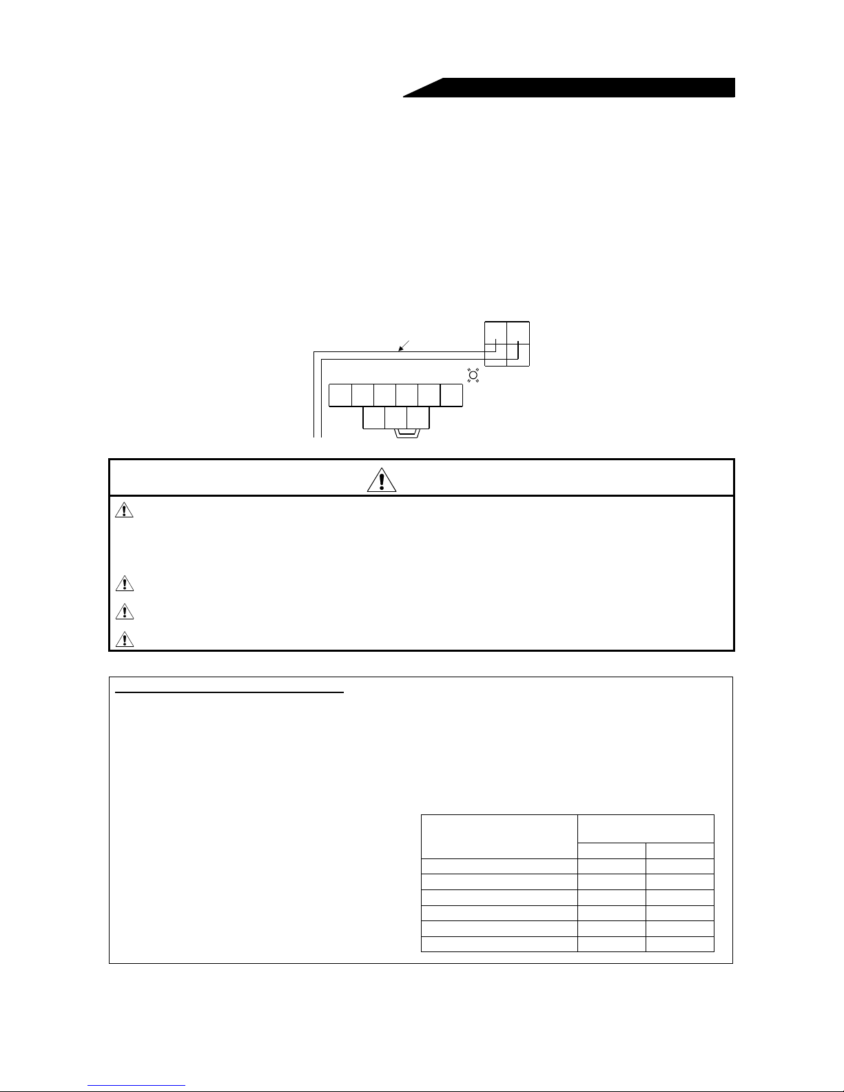
11) Use the space on the left-hand side of the main circuit terminal block to wire the cables for connection of
the control circuit power supply terminals R1, S1 <L11, L21> of the FR-A520-11K.
R1 S1
〉〈
〈
L
L
11
Charge lamp
Screw size (M5)
〉
21
R
〈L1〉S〈L2〉
Connection cable
T
UVW
〈L
〉
3
N
P1
〈−〉
P
〈+〉
CAUTION
Do not use residual current protective device as the only protection against indirect
contact.
Protective earth (ground) connection essential.
Do not connect more than 2 wires on the protective earth (ground) terminal.
Use contactor and no fuse breaker EN/IEC standard compliant.
Use transformer or surge absorber EN/IEC standard compliant.
Notes on Earthing (Grounding)
• Leakage currents flow in the inverter. To prevent an electric shock, the inverter and motor must be
earthed (grounded). Earthing (grounding) must conform to the requirements of national and local safety
regulations and electrical code. (JIS, NEC section 250, IEC 536 class 1 and other applicable standards)
• Use the dedicated earth (ground) terminal to earth (ground) the inverter. (Do not use the screw in the
case, chassis, etc.)
• Use the thickest possible earth (ground) cable.Use
the cable whose size is equal to or greater than
that indicated below, and minimize the cable
length. The earthing (grounding) point should be
as near as possible to the inverter.
• Earth (Ground) the motor on the inverter side
using one wire of the 4-core cable.
Earth (Ground)
Motor Capacity
200V class 400V class
2.2kW (3HP) or less 2 2
3.7kW (5HP) 3.5 2
5.5kW, 7.5kW (7.5HP, 10HP) 5.5 3.5
11kW to 15kW (15 to 20HP) 14 8
18.5kW to 37kW (25 to 50HP) 22 14
45kW, 55kW (60, 75HP) 38 22
(Unit: mm2)
Cable Gauge
16
INSTALLATION AND WIRING
r
)
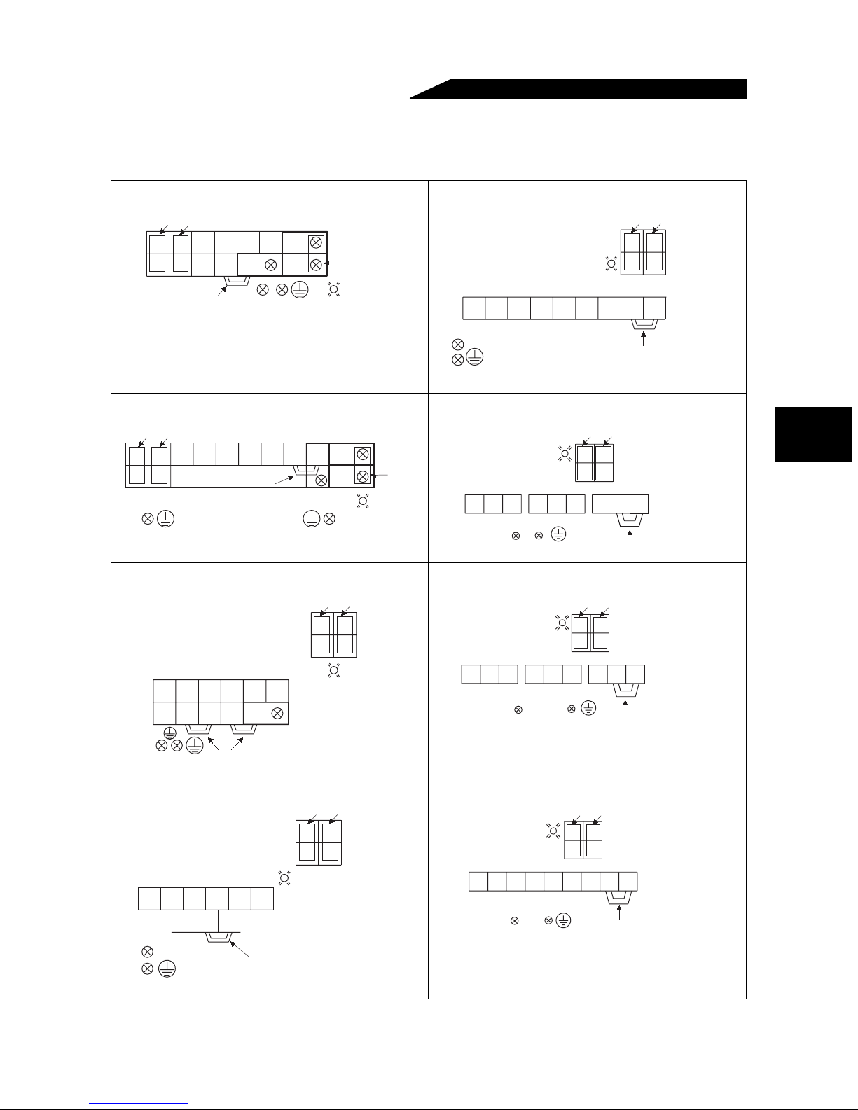
(2) Terminal block layout
In the main circuit of the inverter, the terminals are arranged as shown below:
1) 200V class
FR-A520-0.4K, 0.75K-NA FR-A520-15K, 18.5K, 22K-NA
Jumpers
RR1ST
N/–
S1
Jumper
UVWPR
P1
P/+
Screw size (M4)
PX
Screw size (M4)
Jumper
Charge lamp
RR1S
Screw size (M6)
U
T
Screw size
15K (M6)
18.5K,22K (M8)
Charge lamp
FR-A520-1.5K, 2.2K, 3.7K-NA FR-A520-30K-NA
Jumpers
RR1ST
S1
Screw size (M4)
UVW PRP1
Screw size (M4)
Jumper
N/–
P/+
PX
Charge lamp
Jumpe
Charge lamp
RST UVW
Screw size (M6) Jumper
FR-A520-5.5K, 7.5K-NA FR-A520-37K, 45K-NA
Jumpers
RR1S
N/– P/+
P1 PR PX
UVW
T
RS
Screw size (M5)
Screw size
S1
(M4)
Charge lamp
Charge lamp Screw size (M4)
RR1S
T
Screw size (M8)
VW
Jumpers
R1 S1
RS
N/–
Jumpers
S1
RS
N/– P/+UVW P1
RS
P1
N/–
Jumper
Screw size (M4)
P1 P/+
Jumper
Jumpers
Screw size (M4)
S1
P/+
Screw size (M8)
Screw size (M10
2
Screw size (M5)
Jumpers
FR-A520-11K-NA FR-A520-55K-NA
Charge lamp
RR1S
Screw size (M5)
T
N/– P/+P1
UVW
Jumper
Screw size (M5)
Jumpers
S1
RS
Screw size (M4)
17
Charge lamp
RR1S
T
Screw size (M8)
Jumpers
S1
RS
N/–
Screw size (M4)
P1
P/+UVW
Jumper
Screw size (M12)
INSTALLATION AND WIRING
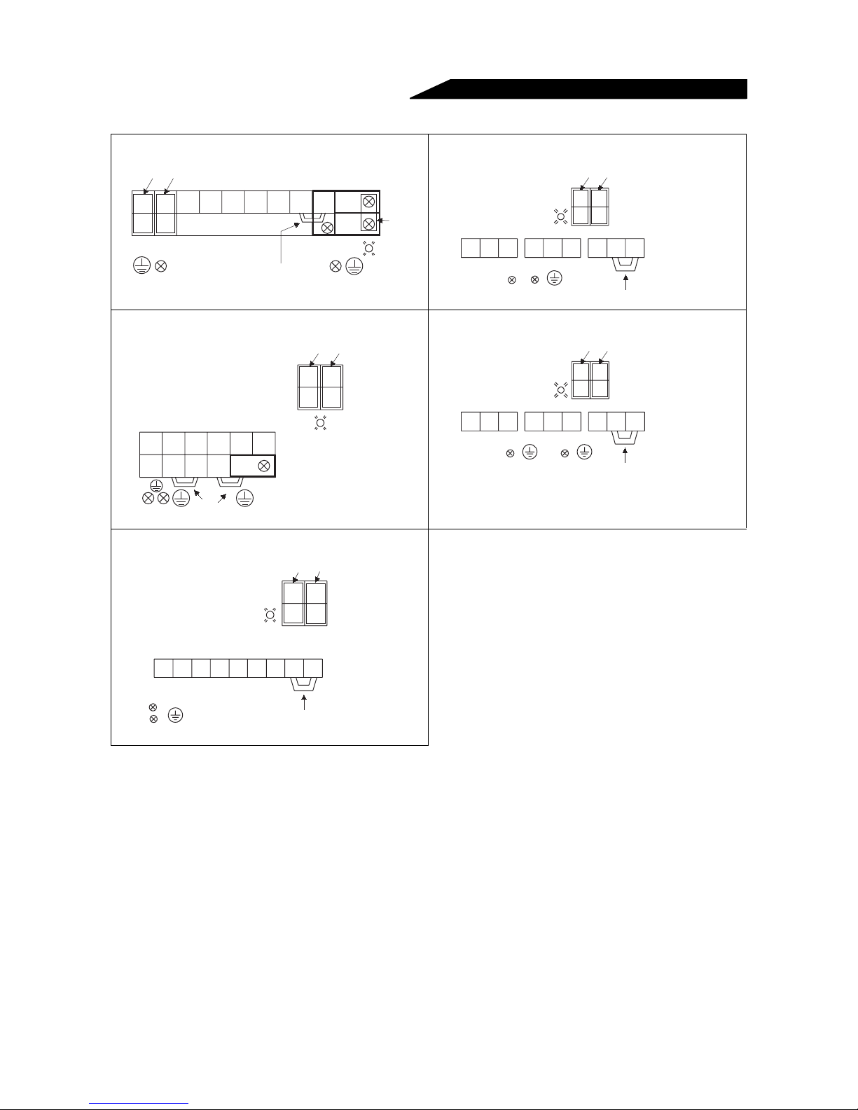
r
)
)
2) 400V class
FR-A540-0.4K, 0.75K, 1.5K, 2.2K, 3.7K-NA/-EC FR-A540-30K-NA/-EC
Jumpers
R
S
<L
1>
<L2>T<L3>
R1
<L11>S1<L21>
Screw size (M4)
UVW PR
Screw size (M4)
P1N/– P/+
Charge lamp
Jumper
SR
L
1
L
2
<
><
><
Screw size (M6)
Charge lamp
T
UVW P1
L
3
>
PX
Jumpe
Jumpers
R1 S1
L
L
11
<
>
RS
L
1
<
>
<
N/–
21
><
2
L
>
Jumper
FR-A540-5.5K, 7.5K-NA/-EC FR-A540-37K, 45K, 55K-NA/-EC
Jumpers
R1 S1
11
><L21>
<L
RS
<L1><L2>
N/– P/+
Jumper
S
R
1>
<L2>T<L3>
<L
P1 PR PX
N/–
Screw size (M4)
UVW
P/+
Jumpers
Jumpers
R1
S1
<L
11>
<L21>
R
<L
1>
<L
Screw size (M4)
Screw size (M4)
S
2>
Charge lamp
<L1>
<L2><L3>
Charge lamp
SRT
Screw size (M8)
UVW P1
FR-A540-11K, 15K, 18.5K, 22K-NA/-EC
Jumpers
R1
S1
Screw size (M4
L
11
21
<>
S
L
1
2
<>
Charge lamp
L
<>
R
L
<>
Screw size (M4)
Screw size (M6)
P/+
Screw size (M4)
Screw size (M8)
S
R
L
L
2
1
<
>< >< >
Screw size (M6)
T
UVW P1
L
3
N/– P/+
Jumper
Screw size (M6
Note: Terminal names in parenthesis are those of the EC version.
18
INSTALLATION AND WIRING
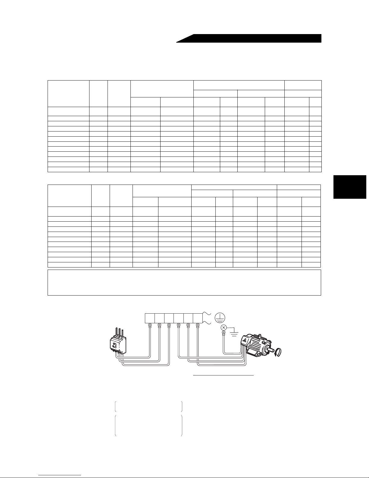
(3) Cables, crimping terminals, etc.
The following table lists the cables and crimping terminals used with the inputs (R, S, T) <L1, L2, L3> and
outputs (U, V, W) of the inverter and the torques for tightening the screws:
•
FR-A520-0.4K to 55K-NA
Applicable Inverter
Typ e
FR-A520-0.4K to
2.2K-NA
FR-A520-3.7K-NA M4 1.5 5.5-4 <4-4> 5.5-4 <2.5-4> 3.5 3.5 12 12 4 2.5
FR-A520-5.5K-NA M5 2.5 5.5-5 <6-5> 5.5-5 <4-5> 5.5 5.5 10 10 6 4
FR-A520-7.5K-NA M5 2.5 14-5 <16-5> 8-5 <6-5> 14 8 6 8 16 6
FR-A520-11K-NA M5 2.5 14-5 <16-5> 14-5 <16-5> 14 14 6 6 16 10
FR-A520-15K-NA M6 4.4 22-6 <35-6> 22-6 <16-6> 22 22 4 4 35 16
FR-A520-18.5K-NA M8 7.8 38-8 <35-8> 38-8 <25-8> 38 38 2 2 35 25
FR-A520-22K-NA M8 7.8 38-8 <70-8> 38-8 <35-8> 38 38 2 2 35 35
FR-A520-30K-NA M8 7.8 60-8 <95-8> 60-8 <30-8> 60 60 1/0 1/0 50 50
FR-A520-37K-NA M10 14.7 100-10 <95-10> 100-10 <70-10> 100 100 4/0 4/0 95 70
FR-A520-45K-NA M10 14.7 100-10 100-10 <95-10> 100 100 4/0 4/0 - FR-A520-55K-NA M12 24.5 150-12 150-12 <110-12> 150 150 MCM300 MCM300 - -
Terminal
Tightening
Screw
Torque
Size
M4 1.5 2-4 <2.5-4> 2-4 <2.5-4> 2 2 14 14 2.5 2.5
N⋅m
Crimping Terminals
R, S, T U, V, W R, S, T U , V, W R, S, T U, V, W R, S, T
HIV Cables (Note 1)
2
mm
AWG mm
• FR-A540-0.4K to 55K-NA/-EC
Applicable Inverter
Typ e
FR-A540-0.4K to 3.7KNA/-EC
FR-A540-5.5K-NA/-EC M4 1.5 5.5-4 <4-4> 2-4 <2.5-4> 3.5 2 12 14 4 2.5
FR-A540-7.5K-NA/-EC M4 1.5 5.5-4 <4-4> 5.5-4 <4-4> 3.5 3.5 12 12 4 4
FR-A540-11K-NA/-EC M6 4.4 5.5-6 <6-6> 5.5-6 <6-6> 5.5 5.5 10 10 6 6
FR-A540-15K-NA/-EC M6 4.4 14-6 <16-6> 8-6 <10-6> 14 8 6 8 16 10
FR-A540-18.5K-NA/-EC M6 4.4 14-6 <16-6> 8-6 <10-6> 14 8 6 8 16 10
FR-A540-22K-NA/-EC M6 4.4 22-6 <25-6> 14-6 <16-6> 22 14 4 6 25 16
FR-A540-30K-NA/-EC M6 4.4 22-6 <25-6> 22-6 <25-6> 22 22 4 4 25 25
FR-A540-37K-NA/-EC M8 7.8 38-8 <37-8> 22-8 <25-8> 38 22 2 4 35 25
FR-A540-45K-NA/-EC M8 7.8 38-8 <50-8> 38-8 <37-8> 38 38 2 2 50 35
FR-A540-55K-NA/-EC M8 7.8 60-8 <70-8> 60-8 <50-8> 60 60 1/0 1/0 50 50
Ter mi na l
Tightening
Screw
Torque
Size
M4 1.5 2-4 <2.5-4> 2-4 <2.5-4> 2 2 14 14 2.5 2.5
N⋅m
Crimping Terminals
R, S, T
<L
1, L2, L3>
U, V, W
R, S, T
<L
1, L2, L3>
HIV Cables (Note 1) PVC insulated Cables
mm
2
U, V, W
AWG mm
R, S, T
<L
1, L2, L3>
U, V, W
Note: 1. The cables used should be 75°C (167°F) copper cables.
2. Tighten the terminal screws to the specified torques.
Undertightening can cause a short or misoperation.
Overtightening can cause the screws and unit to be damaged, resulting in a short or misoperation.
PVC insulated
R, S, T
<L
1, L2, L3>
Cables
2
2
U, V,
U, V, W
W
2
(4) Connection of the power supply and motor
Power
supply
Moulded case
circuit breaker
The power supply cables
must be connected to R, S, T
<L
1, L2, L3>.
If they are connected to U, V,
W, the inverter will be damaged.
Phase sequence need not be
matched.
For use with a single-phase
power supply,the power supply
cables must be connected to
R and S <L
R
1>
<L
RST
<L1>
1 and L2>.
ST
2><L3>
<L
<L
2><L3>
UVW
UVW
Connect the motor to U, V, W.
In the above connection,
turning on the forward rotation
switch (signal) rotates the motor
in the counterclockwise (arrow)
direction when viewed from
the load shaft.
19
Earth (Ground)
terminal
Earth
(Ground)
Motor
INSTALLATION AND WIRING
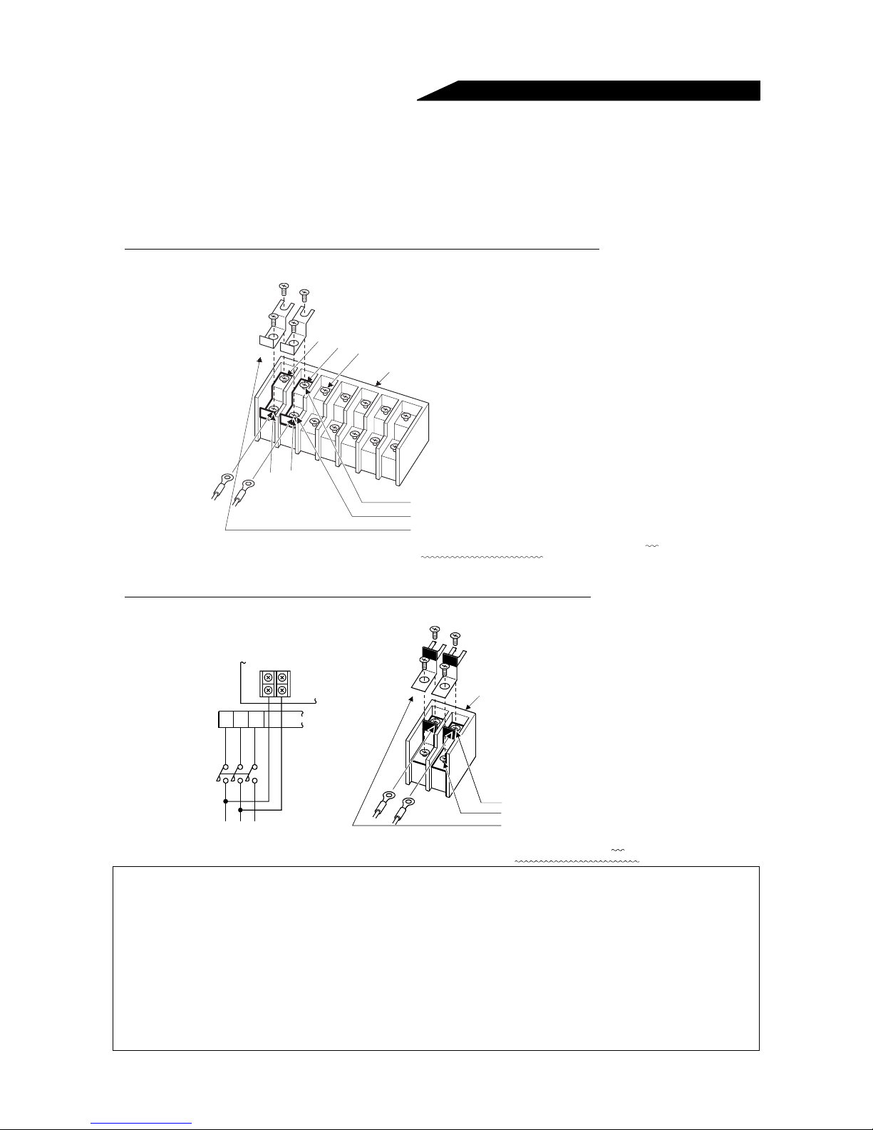
(5) Connecting the control circuit to a power supply separately from the main circuit
If the magnetic contactor (MC) on the inverter power supply side is opened when the protective circuit is
operated, the inverter control circuit power is lost and the alarm output signal cannot be kept on. To keep the
alarm signal, terminals R1 and S1 are available. In this case, connect the power supply terminals R1 and S1
<L
11 and L21> of the control circuit to the primary side of the MC.
• Model FR-A520-0.4K to 3.7K-NA, FR-A540-0.4K to 3.7K-NA/-EC
<Connection procedure>
R
S
<L
1>
T
<L
2>
<L
3>
Terminal block for main circuit
S1
R1
21>
<L
<L
11>
1) Loosen the upper screws
2) Remove the lower screws.
3) Remove the jumpers.
4) Connect the separate power supply cables for control circuit to the
lower terminals (R1, S1 L
, L21).
11
• Model FR-A520-5.5K to 55K-NA, FR-A540-5.5K to 55K-NA/-EC
<Connection procedure>
R1
〉S1〈
〉
〈
L
L
11
21
Power supply terminal
block for control circuit
R
〈
〉S〈
〉T〈
〉
L
L
L
1
2
3
MC
Main power supply
Note: 1. When the main circuit power (R, S, T) <L
(terminals R1, S1 <L
11, L21>). Otherwise the inverter may be damaged.
1 L2, L3> is on, do not switch off the control power
2. When using a separate power supply, the jumpers across R-R1 and S-S1 <L
must be removed. Otherwise the inverter may be damaged.
3. For a different power supply system, which takes the power of the control circuit from other than
the primary side of the MC, the voltage should be equal to the main circuit voltage.
4. For the FR-A520-5.5K to 55K, FR-A540-5.5K to 55K, the power supply cables must not be
connected to the lower terminals. If connected, the inverter may be damaged.
5. Supplying power to only terminals R1 <L
11> and S1 <L21> and entering the start signal will result
in an error display (E.OC1).
Power supply terminal
block for control ci rcuit
1) Loosen the upper screws.
2) Remove the lower screws.
3) Pull out and remove the jumper.
4) Connect the separate power supply
cables for control circuit to the
upper terminals (R1, S1 〈L
〉
, L
). (Note 4)
11
21
1-L11 and L2-L21>
20
INSTALLATION AND WIRING
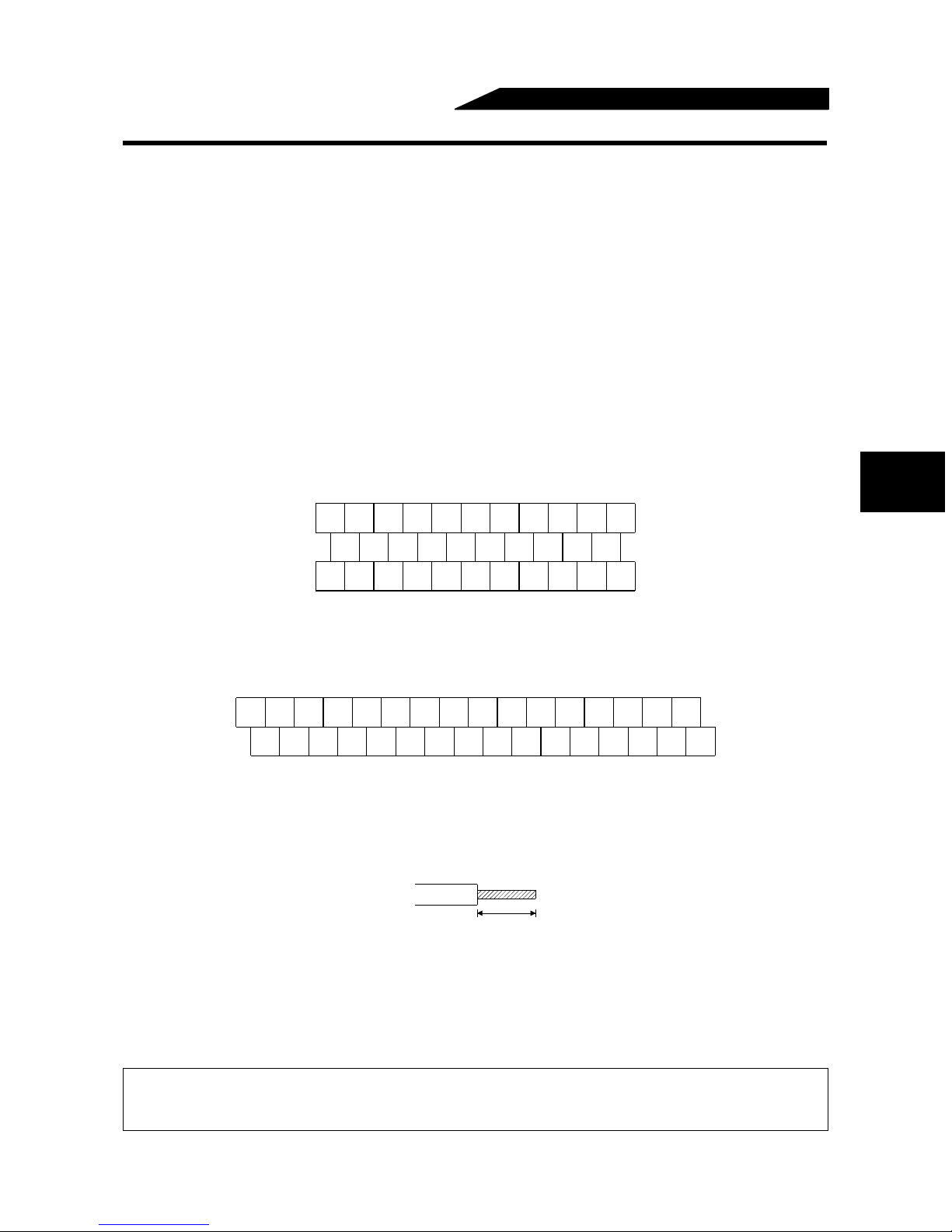
2.2.3 Wiring of the control circuit
(1) Wiring instructions
1) Terminals SD, SE and 5 are common to the I/O signals and isolated from each other. Do not earth
(ground) these terminals. Avoid connecting the terminals SD and 5 and the terminals SE and 5.
2) Use shielded or twisted cables for connection to the control circuit terminals and run them away from the
main and power circuits (including the 200V relay sequence circuit).
3) Since the control circuit input signals are micro currents, use two or more parallel micro signal contacts or
a twin contact to prevent a contact fault.
4) It is recommended to use the cables of 0.75mm
2
If the cable gauge used is 1.25mm
or more, the front cover may be lifted when there are many cables
running or the cables are run improperly, resulting in an operation panel or parameter unit contact fault.
(2) Terminal block layout
• NA version
In the control circuit of the inverter, the terminals are arranged as shown below:
Terminal screw size: M3.5
Tightening torque: 1.2N
⋅m
A
B C PC AM 1 0E 10 2 5 4 1
RM RH RT AU STOP MRS RES SD FM
RL
2
gauge for connection to the control circuit terminals.
2
SE RUN SU IPF OL FU SD STF STR JOG CS
•EC version
Terminal screw size: M3
Tightening torque: 1.2N
⋅m
A
B C SD AM 1 0E 10 2 5 4 1
SE RUN SU LPF OL STOP MRS RES PC STF
RL RM RH RT AU
STR JOG CS FM SDFU
<Wiring procedure>
1) For the wiring of the control circuit, strip the sheaths of the cables and use them as they are.
Strip the sheath to the following dimension. A too long stripping dimension may cause a short circuit with
the neighboring cable. A too short dimension may cause cable disconnection.
6mm ± 1mm
2) Loosen the terminal screw and insert the cable into the terminal.
3) Tighten the screw to the specified torque.
Undertightening can cause cable disconnection or malfunction. Overtightening can cause a short circuit or
malfunction due to the screw or unit damaged.
Note: Wire the stripped cable by twisting it to prevent it from becoming loose. (Do not plate the cable with
solder.)
Note: 1. Use a MCCB (Moulded case circuit breaker) or fuse on the inverter input (primary) side.
2. Make sure that the control circuit terminal wiring does not touch power circuit terminals (or
screws) or conducting power circuit.
21
 Loading...