

Page 1
HC
HIGH POWER FACTOR CONVERTER
FR-HC-7.5K to 55K
FR-HC-H7.5K to H55K
INSTRUCTION MANUAL
Page 2
Thank you for choosing the Mitsubishi High Power Factor Converter.
This instruction manual gives handling information and precautions for use of this equipment. Incorrect
handling might cause an unexpected fault. Before using the invert er, please read this manual care fully to us e
the equipment to its optimum.
Please forward this manual to the end user.
Safety Instructions
Do not attempt to install, operat e, maintain or i nspec t the unit until you have read through this ins tr ucti on
manual and appended docu ments carefully and can use the equipme nt correctly. Do not use the unit
until you have a full knowledge of the equipment, safety information and instructions.
In this instruction manual, the safety instruction levels are classified into “WARNING” and “CAUTION”.
Assumes that incorrect handling may cause hazardous conditions,
WARNING
CAUTION
resulting in death or severe injury.
Assumes that in correc t handl ing may cause h azardou s cond itions, r esulti ng
in medium or slight injury, or may cause physical damage only.
Note that the level may lead to a serious consequen ce accordi ng to con ditions. Plea se
follow the instructions of both levels because they are important to personnel safety.
CAUTION
- A-1 -
Page 3
SAFETY INSTRUCTIO NS
1. Electric Shock Prevention
WARNING
• While power is on or when the equipment is running, do not open the front cover. You may get an
electric shock.
• Do not run the equipment with the front co ver remo ved. Oth erwis e, you may acces s the expo sed high voltage terminals and charging part and get an electric shock.
• If power is off, do not remove the front cover except fo r wiring or periodic inspection . You may access
the charged circuits of the inverter and high power factor converter and get an electric shock.
• Before starting wiring or ins pe ction, ch ec k fo r res i dual v oltages wi th a m ete r etc. more than 10 minutes
after power-off.
• This converter must be ear the d (gr ou nde d). Earthing (grounding) mu st be c on for m to the requi r eme nts
of national and local safety regul ations and electrical codes. (NEC section 250, IEC 536 class 1 and
other applicable standa rd s)
• Any person who is involved in th e wiring or inspection of this equipment should be fully competent to
do the work.
• Always install the equipment before wiring. Otherwise, you may get an electric shock or be injured.
• Operate the switches with dry hands to prevent an electric shock.
• Do not subject the c ab les to s cratc he s, ex ce ss iv e str ess , heavy loads or pi nchi ng. O th er wis e, you may
get an electric shock.
2. Fire Prevention
CAUTION
• Mount the high power fa ctor conver ter on a non- combustible sur face. Installing the equipment directly
on or near a combustible surface could lead to a fire.
• Power off the high power factor converter if it has failed. A continuous flow of a large current can cause
a fire.
• Do not connect a resistor directly to the DC terminals P, N. This could cause a fire.
• When a brake resistor is used, switch po wer off if an alarm signal app ears on the PU. Otherwi se, the
brake resistor may excessively overheat due to damage of the brake transistor, etc., causing a fire.
3. Injury Prevention
CAUTION
• Apply only the volta ge specified in the inst ruction manual to each te rminal to prevent bu rst, damage,
etc.
• Ensure that the cables are connected to the correct terminals. Otherwise, burst, damage, etc. may
occur.
• Always make sure that polarity is correct to prevent burst, damage, etc.
• While power is on or for some time after power-off, do not touch the inverter, high power factor
converter, reactors 1 and 2, or the external box as they are hot and you may get burnt.
- A-2 -
Page 4
4. Additional instructions
To prevent injury, damage or product failure, please note the following points.
(1)Transportation and mounting
CAUTION
• Please use common sense when carrying the product. Not doing so can cause injury.
• Do not stack the equipment higher than the number recommended.
• Install the product in a load-bearing place in accordance with the instruction manual.
• Do not operate if the high power factor converter is damaged or has parts missing.
• Do not lift the equipment with the front cover attached; it may fall off.
• Do not stand or rest heavy objects on the product.
• Check the equipment mounting orientation is correct.
• Prevent any dust, wire fragments or other foreign bodies from dropping into the high power factor
converter.
• Do not drop the high power factor converter, or subject it to impact.
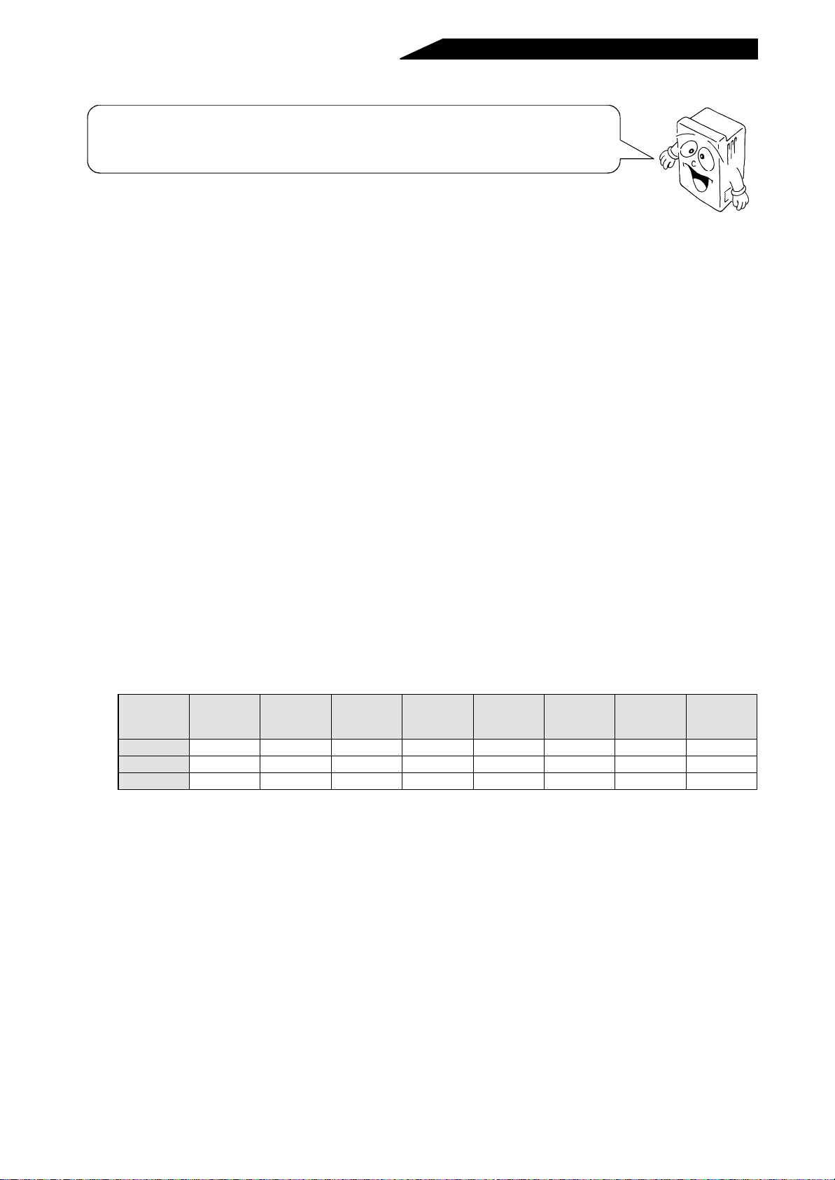
• Use the equipment under the following environmental conditions:
Ambient
temperature
Ambient
humidity
Storage
temperature
Environment
Ambience Indoors (free from corrosive gas, flammable gas, oil mist, dust and dirt)
Altitude,
vibration
*Temperatures applicable for a short time, e.g. in transit.
(-10°C to +40°C when the d ust-protec tion structure attachment is used)
Maximum 1000m above sea level for standard operation.
After that derate by 3% for every extra 500m up to 2500m (91%).
-10°C to +50°C (non-freezing)
90%RH or less (non-condensing )
-20°C to +65°C*
2
5.9m/s
or less
(2)Trail run
CAUTION
• Check all parameters, and ensure that the machine will not be damaged by sudden start-up.
• Before starting operation, e nsure that each peripheral device is wired pr operly. Incorrect connection
may lead to unexpected operation.
(3)Operation
CAUTION
• The load used must be a three-phase induction motor. If any other electrical equipment is connected to
the inverter output, the equipment may be damaged.
• Do not modify the equipment.
- A-3 -
Page 5
(4)Emergency stop
CAUTION
• Provide a safety backup such as an emer gecy brake which will prevent the machine and equipment
from hazardous conditions if the high power factor converter fails.
• When any protective function is activated, take the corresponding corrective action, then reset the
inverter, and resume operation.
(5)Maintenance, inspection and parts replacement
CAUTION
• Do not carry out a megger (insulation resistance) test on the control circuit of the high power factor
converter.
(6)Disposal
CAUTION
• Treat the equipment as industrial waste.
(7)General instructions
Many of the diagrams and drawing in this instruction manual show the equipment without a cover, or
partiall y open. Never run the inverter like thi s. Always replace th e cover and ensure adequate coo ling,
etc. before using the product.
- A-4 -
Page 6

CONTENTS
1. OVERVIEW
1.1 PRECAUTIONS FOR OPERATION ................................ ...... ....................................... ...... ..... ...... ..........................1
1.1.1 Japanese harmonic suppression guideline .......................................................................................................1
1.1.2 Pre-operation procedure ....................................................................................................................................5
1.1.3 Handling precautions .........................................................................................................................................6
1.2 STRUCTURE ...........................................................................................................................................................7
1.2.1 Structure ............................................................................................................................................................7
1.2.2 Removal and reinstallation of the front cover ....................................................................................................8
1.2.3 Removal and reinstallation of the accessory cover .........................................................................................11
1.2.4 Removal and reinstallation of the parameter unit (FR-PU02) ..........................................................................12
1.3 INSTALLATION AND WIRING ................................... ..... ...... ....................................... ...... ..... ..............................13
1.3.1 Precautions for installation ................................... ....................................... ...... ..... .........................................13
1.3.2 Wiring instructions ...........................................................................................................................................16
1.3.3 Wiring of the main circuit ..................... ....................................... ...... ...............................................................17
1.3.4 Wiring of the control circuit .................. ....................................... ...... ...............................................................26
2. PARAMETERS
2.1 PARAMETER UNIT ...............................................................................................................................................29
2.1.1 Structure of the parameter unit ........................................................................................................................29
2.1.2 Setting and changing the parameter values ....................................................................................................30
2.2 PARAMETER FUNCTION DETAILS .....................................................................................................................31
2.2.1 Parameter list ..................................................................................................................................................31
2.2.2 Setting of parameters to improve the corresponding operational functions ....................................................32
Pr.1 “power supply frequency 1”, Pr.2 “power supply frequency 2” .......................................................................32
Pr.22 “overload signal detection level” ..................................................................................................................32
Pr.40 “output terminal assignment” .......................................................................................................................32
Pr. 51 “input power monitoring refer ence”, Pr. 53 “input voltage monitoring reference”, Pr. 55 “bus voltage monitori ng
reference”, Pr. 56 “current monitoring reference” ...................................................................................................33
Pr. 52 “PU main display data selection”, Pr. 54 “FM terminal function selection” ...................................................33
Pr.57 “restart selection” .........................................................................................................................................35
Pr. 65 “retry selection”, Pr. 67 “number of retries at al arm occurrence”, Pr. 68 “retry waiting t ime”, Pr. 69 “retry coun t
display erasure” ........................................................... ..... ........................................ ..... .........................................36
Pr.77 “parameter write disable selection” ..............................................................................................................37
Pr.145 “parameter unit language switching” ..........................................................................................................37
Pr.900 “FM terminal calibration” ............................................................................................................................38
2.3 HELP FUNCTIONS ................................................................................................................................................40
2.3.1 Definitions of the help function displays ..........................................................................................................40
2.4 CONVERTER RESET ............................................................ ...... ..... ...... ..... ...... ....................................................43
3. PROTECTIVE FUNCTIONS
3.1 ERRORS ................................................................................................................................................................44
3.1.1 Error (alarm) definitions and remedies .............................................................. ..... ...... ...................................44
3.1.2 Faults and check points ...................................................................................................................................45
- I -
Page 7

3.2 MAINTENANCE AND INSPECTION .....................................................................................................................46
3.2.1 Precautions for maintenance and inspection ...................................................................................................46
3.2.2 Check items .....................................................................................................................................................46
3.2.3 Replacement of parts ...................................................................................................................................... 49
3.2.4 Measurement of main circuit voltages, currents and powers ..........................................................................50
4. PRECAUTIONS FOR SELECTION
4.1 PRECAUTIONS FOR SELECTING PERIPHERAL DEVICES ..............................................................................52
4.1.1 Measures against noises .................................................................................................................................52
4.1.2 Peripheral device list .......................................................................................................................................55
4.1.3 Selecting the rated sensitivity current for the earth leakage circuit breaker ....................................................55
5. SPECIFICATIONS
5.1 SPECIFICATIONS .................................................................................................................................................56
5.1.1 Standard specifications ...................................................................................................................................56
5.1.2 Block diagram ..................................................................................................................................................57
5.1.3 Terminals .........................................................................................................................................................58
5.1.4 Terminal block arrangement ............................................................................................................................60
5.1.5 Outline drawings (400V class models have H in their type codes) ..................................................................61
5.1.6 Panel cutting dimension diagrams (For use of the heat sink outside mounting attachment) ...........................66
5.1.7 Parameter unit (FR-PU02-1/FR-PU02E-1/FR-PU02ER-1) dimension diagram ..............................................67
5.2 OPTIONS ...............................................................................................................................................................68
5.2.1 Option list .........................................................................................................................................................68
5.2.2 External dedicated options ..............................................................................................................................69
APPENDIX
APPENDIX 1 INSTRUCTIONS FOR COMPLIANCE WITH THE EUROPEAN STANDARDS .............................73
APPENDIX 2 Instructions for UL and cUL ..........................................................................................................74
- II -
Page 8

1. OVERVIEW
2. PARAMETERS
3. PROTECTIVE FUNCTIONS
4. PRECAUTIONS FOR SELECTION
5. SPECIFICATIONS
Page 9

1. OVERVIEW
This chapter provides an “overview” of this product.
Always read the precautions, etc. before starting use.
1
1.1 PRECAUTIONS FOR OPERATION........................................................... 1
1.2 STRUCTURE ............................................................................................. 7
1.3 INSTALLATION AND WIRING................................................................... 13
Page 10
1.1 PRECAUTIONS FOR OPERATION
Incorrect handling might cause the equipment to operate improperly, its life to be reduced
considerably, and in the worst case, the high power factor converter and inverter to be
damaged. Please handle the unit properly in accordance with the information on each
section as well as the precautions and instructions of this manual.
FR-HC Function
The FR-HC high power factor converter provides three functions
1) Inverter generated mains harmonics reduction
See the Power harmonic guideline section below.
2) Near unity power factor at 100% load
Gives better efficiency and lower stress on power line components.
3) Regeneration of load to the mains power supply
The FR-HC can con tinuously re generate conver ter rated current t o the power su pply, for example from
a ‘back-driving’ load such as a d own escalator. This gives very efficient full 4-quadrant control of the
AC motor from the inverter without the need for brake resistors or braking units etc.
1.1.1 Japanese harmonic suppression guideline
Harmonic c urrents flow from th e inverter to a power receiv ing point via a p ower transformer. The harmonic
suppression guideline was established to protect other consumers from these outgoing harmonics.
1) “Harmonic suppression guideline for household appliances and general-purpose products”
200V class inver ters of 3.7kW and less are covered by this guideline. Install a power factor improving
reactor to comply with this guideline.
2) “Harmonic suppression guideline for specific consumers”
This guideline sets forth the maximum values of harmonic currents outgoing from a high-voltage or
specially high-voltage con sumer who will install, add or renew harm onic generating equipment. If any
of the maximum values is exceeded, this g uideline requ ires that c onsumer to ta ke cer tain suppre ssion
measures.
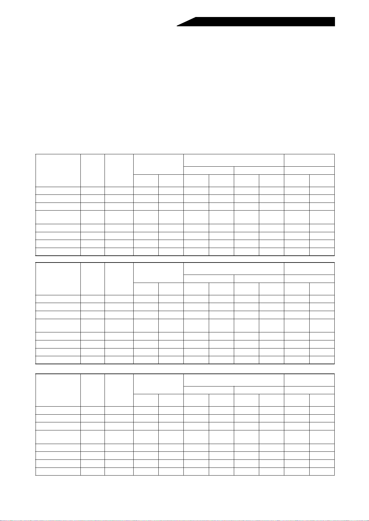
Table 1 Maximum Values of Outgoing Harmonic Currents per 1kW Contract Power
Received
Power
Voltage
6.6kV 3.5 2.5 1.6 1.3 1.0 0.9 0.76 0.70
22kV 1.8 1.3 0 .82 0.69 0.53 0.47 0.39 0.36
33kV 1.2 0.86 0.55 0.46 0.35 0. 32 0.26 0.2 4
5th 7th 11th 13th 17th 19th 23rd
over
23rd
- 1 -
Page 11
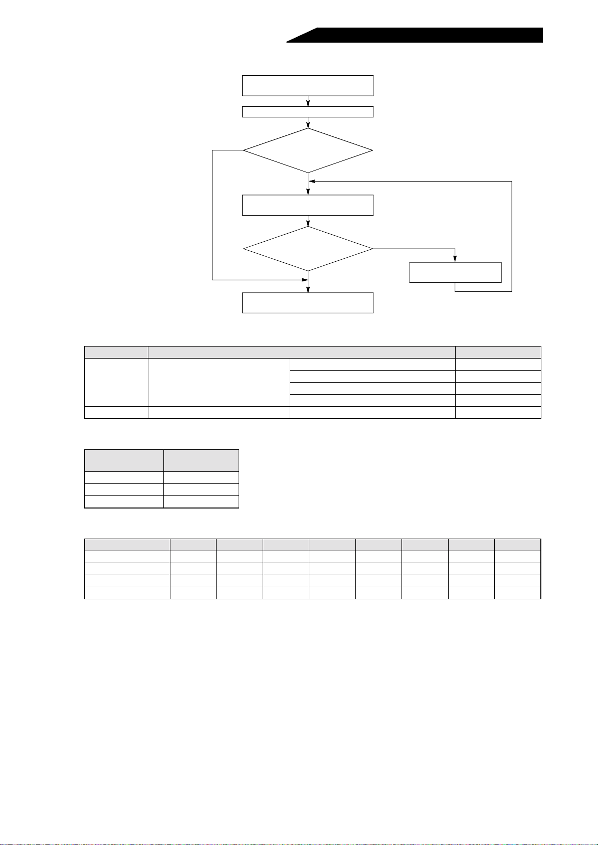
(1) Application of the harmonic suppression guideline for specific consumers
New installation/addition/renewal of
harmonic generating equipment
Calculation of equivalent capacity sum
Not more than
reference capacity
Over reference capacity
Sum of equivalent capacities
Calculation of outgoing harmon ic
current higher than maximum
Harmonic suppression techn iq ue is
current
Is outgoing harmonic
value?
Not more than
maximum value
not required.
Over maximum value
Harmonic suppression
technique is required.
Table 2 Conversion Factors for FR-A500 Series
Classification Circuit Type Conversion Factor
Without reactor K31=3.4
3
Three-phase bridge
(Capacitor smoothed)
With reactor (on AC side) K32=1.8
With reactor (on DC side) K33=1.8
Without reactor (on AC/DC side) K34=1.4
5 Self-excited three-phase bridge When high power factor converter is used K5=0
Table 3 Equivalent Capacity Limits
Received Power
Voltage
6.6kV 50kVA
22/23kV 300kVA
66kV or more 2000kVA
Reference
Capacity
Table 4 Harmonic Content (Values at the fundamental current of 100%)
Reactor 5th 7th 11th 13th 17th 19th 23rd 25th
Not used 65 41 8.5 7.7 4.3 3.1 2.6 1.8
Used (AC side) 38 14.5 7.4 3.4 3.2 1.9 1.7 1.3
Used (DC side) 3 0 13 8.4 5.0 4.7 3.2 3.0 2.2
Used (AC, DC sides) 28 9.1 7.2 4.1 3.2 2.4 1.6 1.4
- 2 -
Page 12
1) Calculation of equivalent capacity P0 of harmonic generating equipment
Σ
The “equivalent capacity” is the capacity of a 6-pulse converter converted from the capacity of a
consumer’s harmonic generat ing equip ment and i s calcula ted with the following equation. If the s um of
equivalent capacities is hig her than the limit in Table 3, har monics must be calcul ated in the following
procedure:
P0 = (Ki×Pi) [kVA]
Ki: Conversion factor (refer to Table 2)
Pi: Rated capacity of harmonic
generating equipment* [kVA]
i: Number indicating the conversion
circuit type
* Rated capacity: Determined by the
capacity of the applied motor and found
in Table 5. It should be noted that the
rated capacity used here is used to
calculate generated harmonic amount
and is different from the power supply
capacity require d for actual inverter drive.
2) Calculati on of outgoi ng harmonic current
Outgoing harm oni c
current
=
(value converted from received power voltage)
fundamental wave current
operation
×
ratio
harmonic
×
content
• Operation ratio: Operation ratio = actual load factor × operation tim ratio during 30 minutes
• Harmonic content: Found in Table 4.
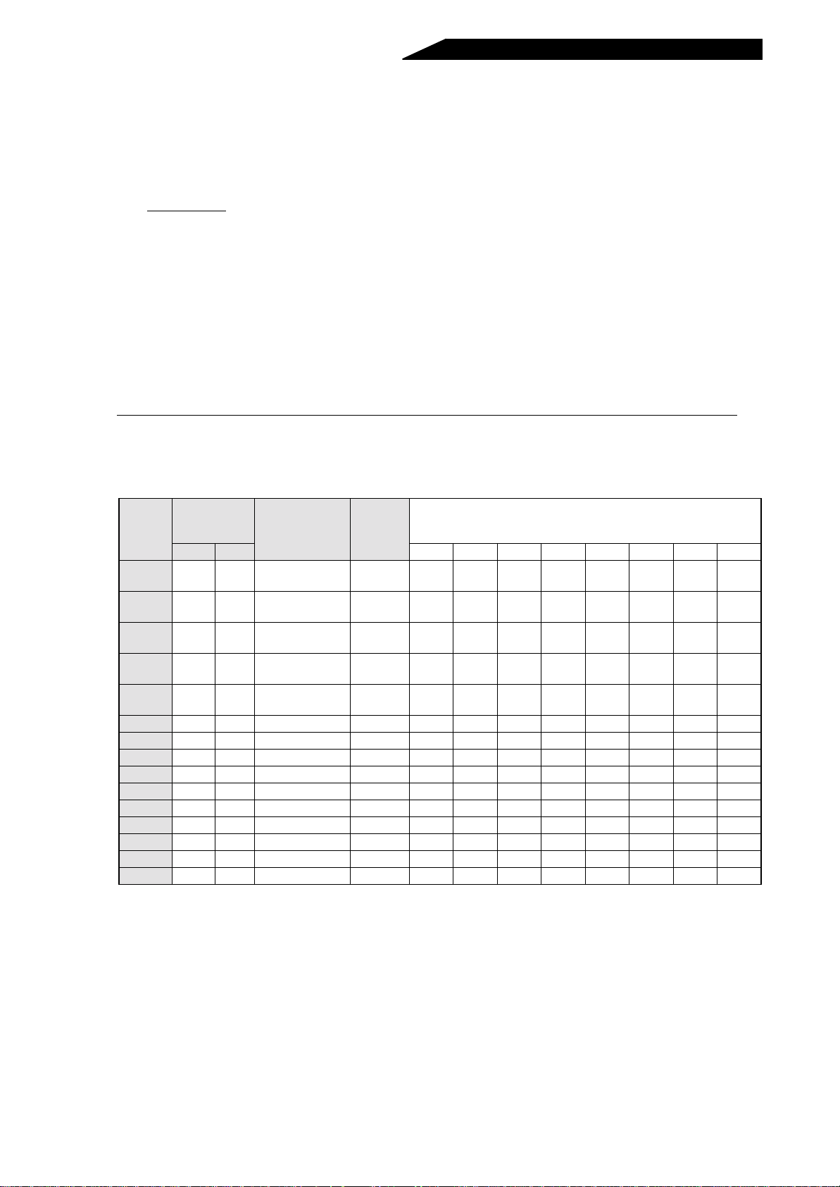
Table 5 Rated Capacities and Outgoing Harmonic Currents for Inverter Drive
Applied
Motor
(kW)
0.4
0.75
1.5
2.2
3.7
5.5 19.1 9.55 579 6.77 376.1 237.4 49.22 44.58 24.90 17.95 15.05 10.42
7.5 25.6 12.8 776 9.07 504.4 318.2 65.96 59.75 33.37 24.06 20.18 13.97
11 36.9 18.5 1121 13.1 728.7 459.6 95.29 86.32 48.20 34.75 29.15 20.18
15 49.8 24.9 1509 17.6 980.9 618.7 128.3 116.2 64.89 46.78 39.24 27.16
18.5 61.4 30.7 1860 21.8 1209 762.6 158.1 143.2 79.98 57.66 48.36 33.48
22 73.1 36.6 2220 25.9 1443 910.2 188.7 170.9 95.46 68.82 57.72 39.96
30 98.0 49.0 2970 34.7 1931 1218 252.5 228.7 127.7 92.07 77.22 53.46
37 121 60.4 3660 42.8 2379 1501 311.1 281.8 157.4 1 13.5 95.16 65.88
45 147 73.5 4450 52.1 2893 1825 378.3 342.7 191.4 1 38.0 115.7 80.10
55 180 89.9 5450 63.7 3543 2235 463.3 419.7 234.4 1 69.0 141.7 98.10
Rated
Current
[A]
200V 400V 5th 7th 11th 13th 17th 19th 23rd 25th
1.61
(Note)
(Note)
(Note)
(Note)
(Note)
0.81 49 0.57 31.85 2 0.09 4.165 3.773 2.107 1.519 1.274 0.882
2.74
1.37 83 0.97 53.95 3 4.03 7.055 6.391 3.569 2.573 2.158 1.494
5.50
2.75 167 1.95 108.6 68.47 14.20 12.86 7.181 5.177 4.342 3.006
7.93
3.96 240 2.81 156.0 98.40 20.40 18.48 10.32 7.440 6.240 4.320
13.0
6.50 394 4.61 257.1 161.5 33.49 30.34 16.94 12.21 10.24 7.092
Fundamental
Wave Current
Converted fr om
6.6kV (mA)
Rated
Capacity
(kVA)
Fundamental Wave Current Converted from 6.6kV(mA)
(No reactor, 100% operation ratio)
Note:When a motor of 3.7kW or less capaci ty is driven by a transistorized inverter of more than 3.7kW.
For example, when a 3.7kW or less motor is driven by a 5.5kW transistorized inverter, the
transistorized inverter is not the target of the household appliances/general-purpose products
guideline, but because they must be included in the calculation of the har monic current of the
guideline, the fundamental wave input currents are indicated.
3) Harmonic suppression technique requirement
contract
If the outgoing harmoni c current is higher than the maximum value per 1kW co ntract power ×
power, a harmonic suppression technique is required.
- 3 -
Page 13
4) Harmonic suppression techniques
No. Item Description
Reactor installation
1
(ACL, DCL)
High power factor
2
converter (FR-HC)
Installation of power
3
factor improving capacitor
Transformer multi-phase
4
operation
5AC filter
6 Active filter
Install a reactor (ACL) in the AC side of the inverter or a reactor (DCL) in its DC s ide or
both to suppress harmonic currents.
Designed to switch the converter circuit on-off to convert an input current waveform into
a sine wave, the high power factor converter (FR-HC) suppresses harmonic current
considerably. The FR-HC is used with the standard accessories.
When used with a series reactor, the power factor improving capacitor has an effect of
absorbing harmonic currents.
Use two transformers with a phase angle difference of 30° as in - , - combination to
provide an effect corresponding to 12 pulses, reducing low-degree harmonic currents.
A capacitor and a reactor are used together to reduce impedance at specific
frequencies, producing a great effect of absorbing harmonic currents.
This filter detects the current of a circuit generating a harmonic current and generates a
harmonic current equivalent to a difference between that current and a fundamental
wave current to suppress a harmonic current at a detection point, providing a great
effect of absorbing harmonic currents.
∆∆∆
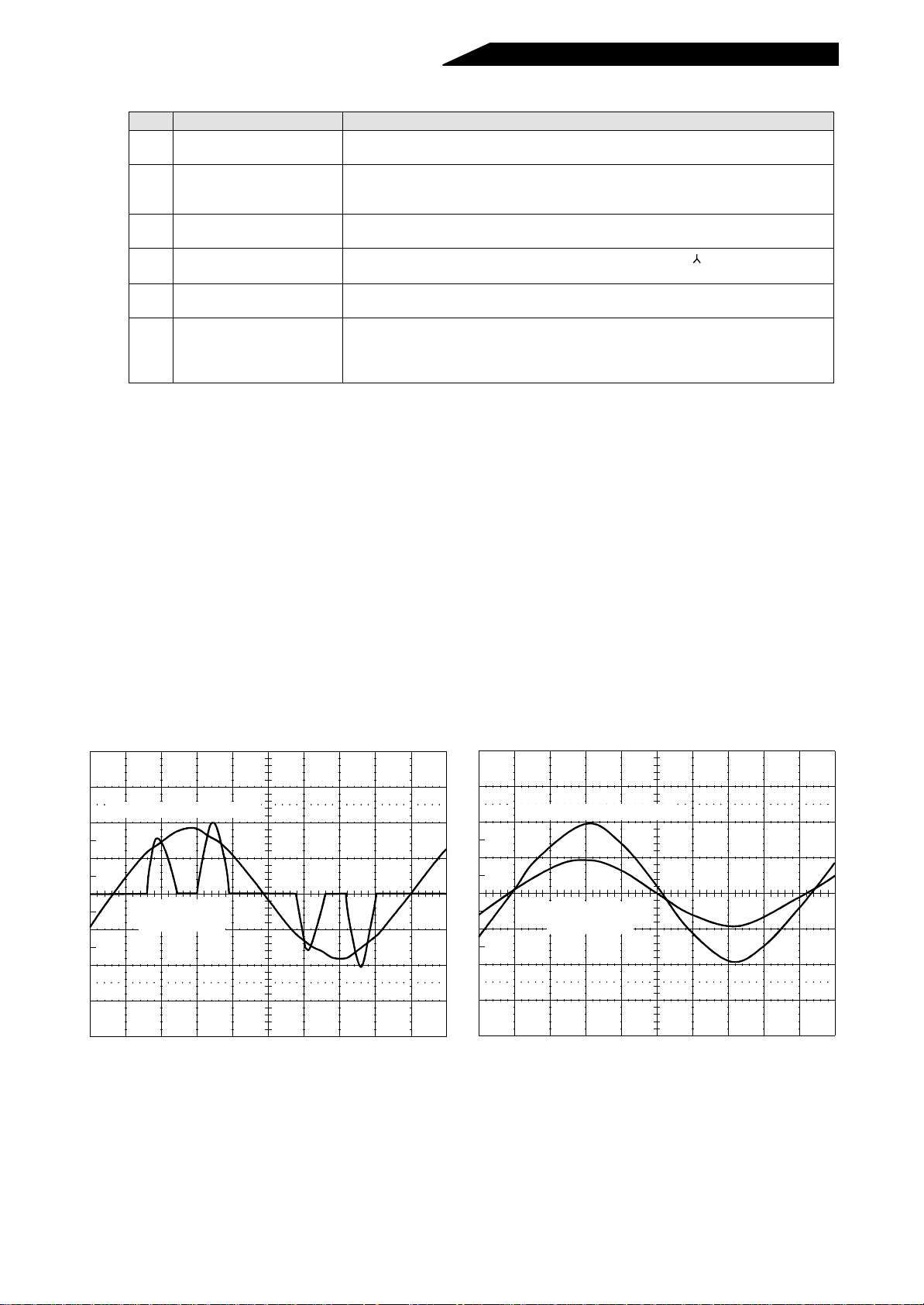
(2) Features of the FR-HC (high power factor converter)
The converter circuit of an inverter generates power harmonics, which may affect a generator, power
capacitor, etc. Power harmonics are different from noises and leakage currents in their sources,
frequency bands and transmission routes. Th erefore, securely connect the high power factor converter
(FR-HC) with the FR series inverter, and refer to the inverter instruction manual on how to set the
parameters. The conversion factor of the high power factor converter is K5=0 for a self-excited, threephase bridge circuit:
Making the above settings suppresses power harmonics to conform to the harmonic suppression
guidelines published by the Ministry of International Trade and Industry.
• Power harmonic su ppr ess ion effect
(Example) FR-HC-7.5K
(Environment) Load: 100%
Power factor: 1
[FR-HC not connected]
Phase voltage (100V/div)
Phase current
(50A/div)
Phase voltage (100V/div)
Phase current
[FR-HC connecte d]
(50A/div)
- 4 -
Page 14
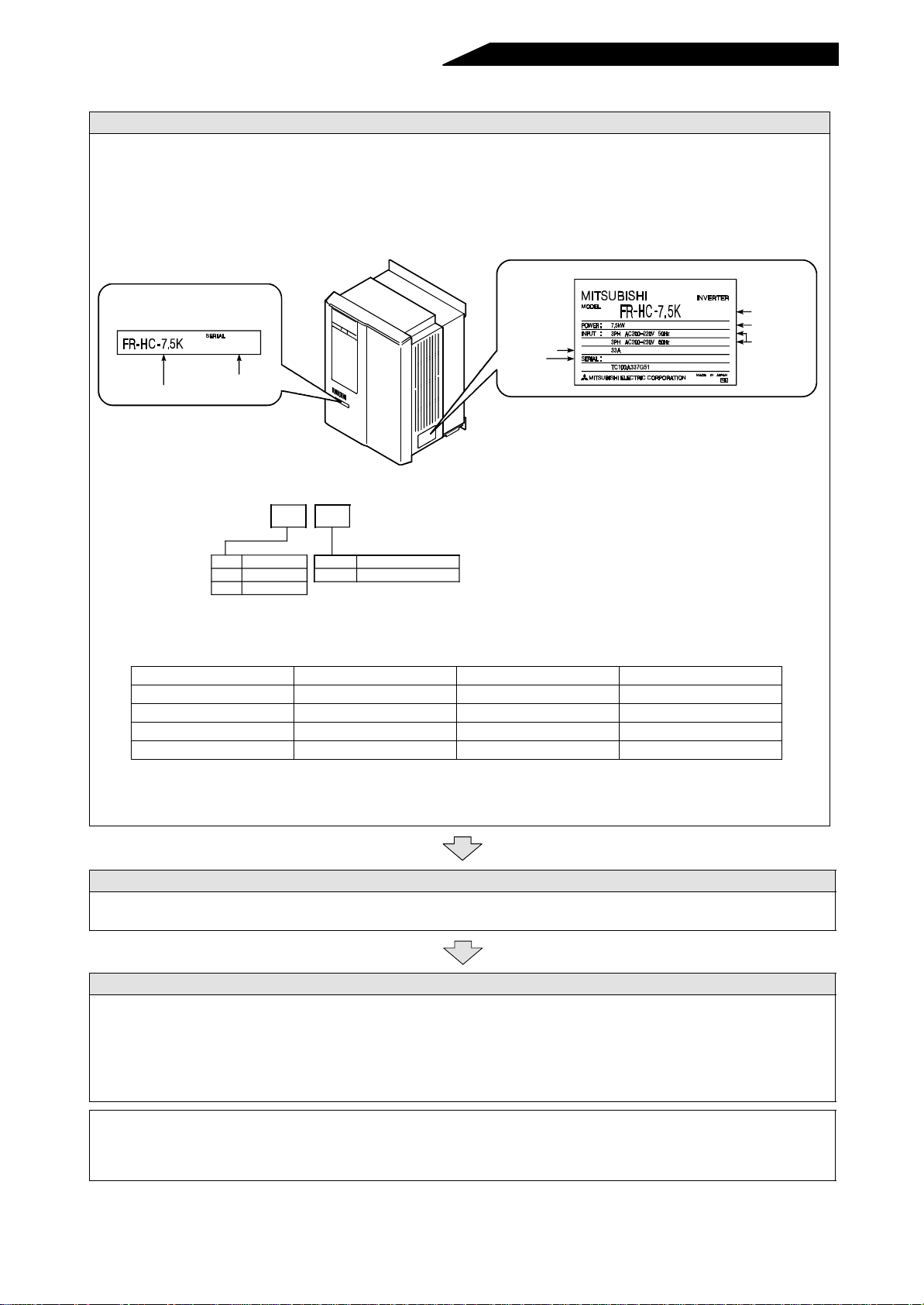
1.1.2 Pre-operation procedure
1. Unpacking and product check
Unpack the product and ch eck the ca pa ci ty plat e on t he fron t cover and the ratin g pl at e on the equ ip me nt
side face to ensure that the type and output rating agree with your order and the product is intact.
When using reactors 1, 2 and the external box, especially when they are used with the Mitsubishi
transistorized inverter be sure to us e them as a set and make sure they are securely con nected. This
high power factor converter suppresses har monics according to the harmonic suppressio n guidelines
published by Ministry of Economy Trade and Industry (formerly Ministry of International, Trade and
Industry). Pay attention to the applicable capacity, etc.
Rating plate
Capacity plate
High power factor
converter type
Serial number
Rated input
current
Serial number
Converter type
Applicable inverter
capacity
Applicable power
supply
• Definition of the high power factor converter type
FR-HC- K
Symbol
Symbol
None
H
Voltage class
200V class
400V class
7.5 to 55
Applicable inverter capacity
Capacity in "kW"
• Confirmation of the peripheral device types
The following three peripheral devices, FR-HCL01, FR-HCL02 and FR-HCB, must be installed.
Confirm their types:
High Power Factor Converter
FR-HC-7.5K FR-HCL01-7.5K FR-HCL02-7.5K FR-HCB-7.5K
FR-HC-15K FR-HCL01-15K FR-HCL02-15K FR-HCB-15K
FR-HC-30K FR-HCL01-30K FR-HCL02-30K FR-HCB-30K
FR-HC-55K FR-HCL01-55K FR-HCL02-55K FR-HCB-55K
Reactor 1 Reactor 2 External Box
Note: 400V class devices have capacity numbers preceded by H in their type codes.
• Accessory . . . . . . Instruction manual
If you have found any discrepancy, damage, etc., please contact your sales representative.
2. Installation
To operate the product with high performance for a long time, install it in a p roper place, in a correct
direction, and with proper clearances. (See page 13.)
3. Wiring
Securely connec t the p ower supply, reactors 1, 2, external box, high power factor converter a nd inver ter
to the terminal blocks.
If they are connected im properly, the periph eral devices and the high power factor converter itself may
be damaged. (See page 16.)
After making su re that the wiring is secured, refer to the i nverter instruc tion manual on how to set the
parameters.
Note: If the inverter is provided with a jum per connector for sink and source logic change, fit the jumpe r
connector to the sink logic (factor y settin g) when c onnecting a high power factor converter (FR-HC).
If the jumper connector is fitted to the source logic, the converter cannot be connected.
- 5 -
Page 15

1.1.3 Handling precautions
The following system is required to operate the inverter. Install the high power factor converter in a proper
position. For the selection and specifications of each peripheral device, refer to “Precautions for Selecting
Peripheral Devices” on page 52:
Name Description Refer to Page:
Use the power supply within the
Power supply
permissible power supply specifications
of the high power factor conve rter .
56
Earth leakage
circuit
breaker or no-fuse
breaker
Magnetic
contactor
Reactor 1
FR-HCL01
External box
FR-HCB
Reactor 2
FR-HCL02
High power factor
converter
The breaker should be selected with
care since a large inrush current flows
in the high power factor converter at
power on.
Install the magnetic contactor to
ensure safety.
When installed, do not use it to start
or stop the inverter. It might reduce
the high power factor converter life.
Make sure that the reactor has a
proper capacity which matches the
high power factor converter capacity.
Make sure that the external box has a
proper capacity which matches the
high power factor converter capacity.
Make sure that the reactor has a
proper capacity which matches the
high power factor converter capacity.
Install and wire the equipment
correctly.
Note: Do not install a no-fuse breaker
(NFB) across terminals P -P and
N-N of the high power factor
converter and the inverter.
55
55
62
64
62
13
Ground
Inverter
Devices
connected to the
output
Motor
Ground
Make sure that the inverter is
compatible with the FR-HC.
Connect the inverter suitable for the
capacity of the high power factor
converter.
Do not connect a power capacitor,
surge suppressor or radio noise filter
to the output side.
Note: When installing a no-fuse
breaker (NFB) on the output
side, contact the NFB
manufacturer for selection of
no-fuse breaker.
Connect the motor suitable for the
capacity.
To prevent an accidental electric shock,
always ground the high power factor
converter, external box, inverter and
motor.
56
Instruction
manuals of the
devices
connected on
the output side
Inverter
instruction
manual
Inverter
instruction
manual
- 6 -
Page 16
1.2 STRUCTURE
This section covers the structure, installation and removal of the equipment.
In this manual, equipment parts are described with the following names.
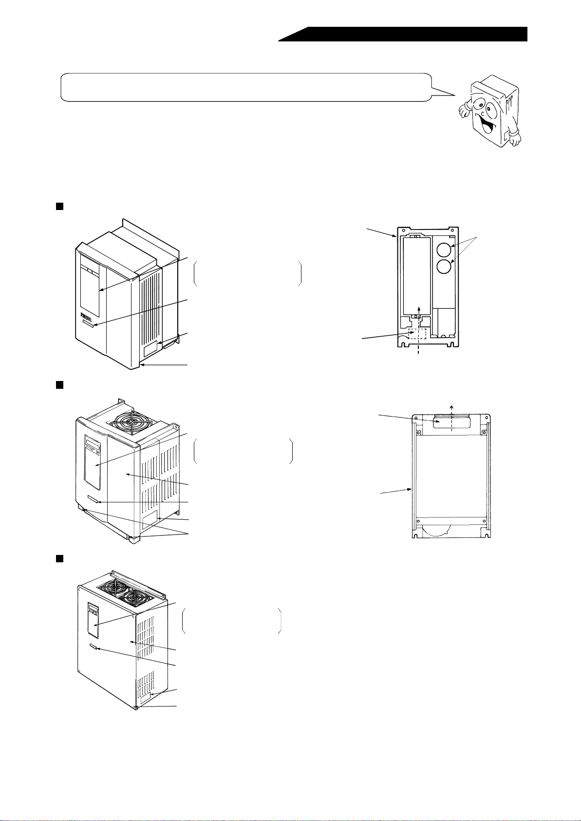
1.2.1 Structure
The high power factor converter models have the following parts as shown below.
For the location of the charge lamp, refer to “Terminal block arrangement” on page 60.
FR-HC-7.5K/H7.5K
Chassis
Accessory cover
When using the parameter unit, re-
move this accessory cover and install
the parameter unit in this position.
Capacity plate
Rating plate
Front cover
Cooling fan
Cooling air
Capacitors
FR-HC-15K/H15K
Cooling air
Cooling fan
Accessory cover
When using the parameter unit, remove this accesso ry cover and inst all
the parameter unit in this position.
Front cover
Capacity plate
Rating plate
Front cover installation screws
Chassis
(Plastic)
FR-HC-30K, 55K/H30K, H55K
Accessory cover
When using the parameter unit, remove this accessor y cover and instal l
the parameter unit in this position.
Front cover
Capacity plate
Rating plate
Front cover installation screws
Note:Dimensions vary with the capacity . F or full information, refer to “Outline Dimension Drawings” on page 61.
- 7 -
Page 17
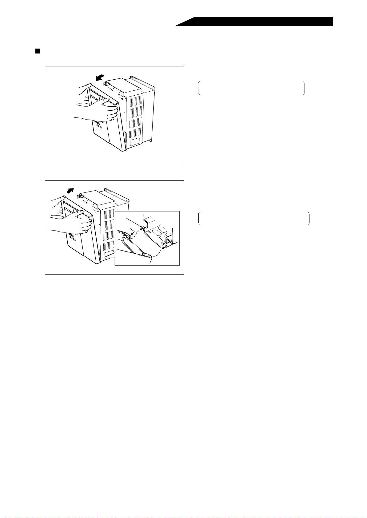
1.2.2 Removal and reinstallation of the front cover
FR-HC-7.5K/H7.5K
• Removal
• Reinstallation
Catch
Socket
1) Hold both sides of the front cover top.
2) Pull the cover toward you.
The cover may be removed with the
parameter unit on.
1) Fit the sockets at the cover bottom onto the
catches of the inverter.
2) Using the c atche s as supp orts, securely pr ess
the cover against the inverter.
The cover may be reinstalled with the
parameter unit on.
- 8 -
Page 18
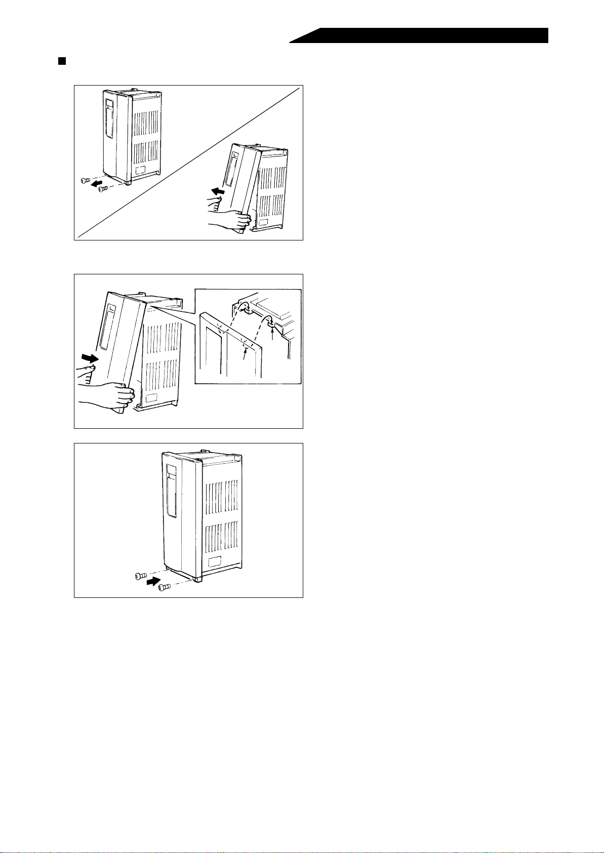
FR-HC-15K/H15K
• Removal
• Reinstallation
1) Remove the two installation screws at the
bottom of the front cover.
2) Hold both ends of the front cover bottom and
pull the cover toward you
1) Fit the catches on t he inside of the front cover
top into the sockets of the inverter.
2) Securely press the cover against the inverter.
Socket
Catch
3) Fix the cover with the bottom installation
screws.
- 9 -
Page 19
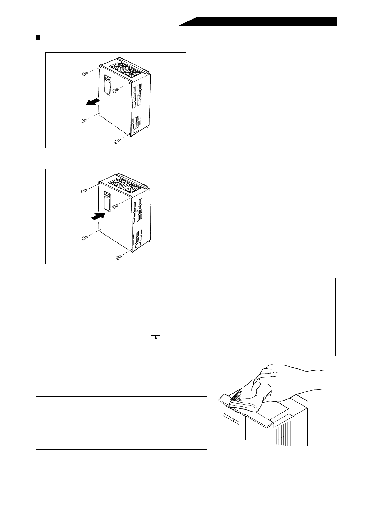
FR-HC-30K, 55K/H30K, H55K
• Removal
• Reinstallation
1) Remove the front cover installation screws.
1) Attach the front cover with the installation
screws.
Note: 1.Fully check that the front cover has been reinstalled securely.
2.The serial numbe r is printed on bot h the capacity plate o n the front cover and the rating plate on
the high power factor converter side face. Before reinstalling the front cover, check the serial
numbers are the same.
Example:
Capacity plate A46152
Rating plate A46152 001
3-digit serial number
If the high power factor converter surface is stained with
fingerma rks, oil, et c. dur ing removal and/or rei nstallation work,
gently clean it with a cloth soa ked with a neutral detergent or
ethanol.
Note: 1.Do not use any solvent, such as acetone, benzene,
toluene and alco hol, that will cause the hig h power
factor converter surface to dissolve and the paint to
peel.
2. Do not clean the lens of the high power factor
converter’s power lamp with a detergent or alcohol.
- 10 -
Page 20
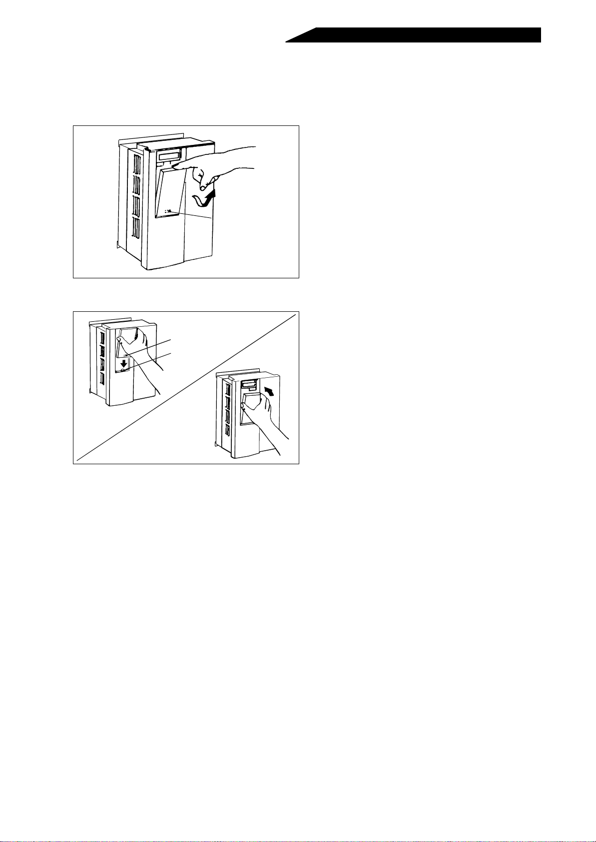
1.2.3 Removal and reinstallation of the accessory cover
To ensure safety, remove and reinstall the accessory cover after switching the power off.
• Removal
1) As in the re moval of the parameter unit, h old
down the top and pull the accessory cover
toward you, using the catch as a support.
Catch
• Reinstallation
1) After fitting th e fixing hole onto t he ca tch of the
cover, push it into the inverter.
Fixing hole
Catch
- 11 -
Page 21
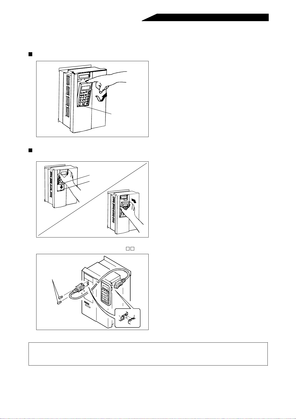
1.2.4 Removal and reinstallation of the parameter unit (FR-PU02)
To ensure safety, remove and reinstall the parameter unit after switching the power off.
Removal
1) Hold down the top button of the parameter unit
and pull the parameter unit toward you, using
the catch as a support.
Catch
Reinstallation
• Direct installation onto the high power factor converter
1) After fitting the fixing hole of the parameter unit
(PU) on the catch of the cover, confirm the
Fixing hole
Catch
connector position and push the parameter
unit into the inverter, using the catch as a
support.
• Installation using the cable (FR-CBL )
1) Securely inser t one connector of the cable into
the connector of the high power factor
converter and the other cable connector into
Installation screws
the PU connector. Insert the cable connector
along the guides. (If the orientation is
incorrect, the high power factor converter may
be damaged.)
2) After plugging the cable connector into the
high power factor converter connector, fix it
Guide
securely with the in stallation screws.
Note: 1.The parameter unit must only be installed on the high power factor converter when t he front cover
is fitted.
2.During installation, do not apply force to the display (liquid crystal).
- 12 -
Page 22
1.3 INSTALLATION AND WIRING
Incorrect handling might cause the equipment to operate improperly, its life to be reduced
considerably, and in the worst case, the high power factor converter and inverter to be
damaged. Please handle the unit properly in accordance with the information on each
section as well as the precautions and instructions of this manual.
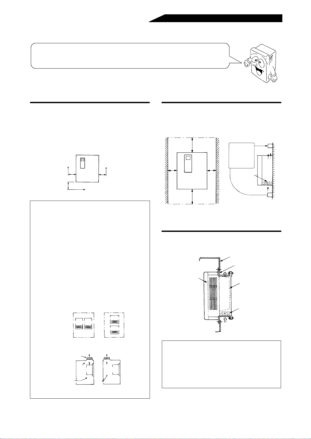
1.3.1 Precautions for installation (1) Installation of the high power factor converter
Instructions for ambient temperatures
The lives of the high power factor converter and
reactors 1, 2 are affected considerably by ambient
temperatures. Keep their ambient temperatures
below the permissible value (50°C). Measure the
ambient temperatures in the following positions to
make sure that they are within the permissible
range.:
Measurement position
5cm
5cm
FREQROL
Measurement position
Note: 1.When the high power factor converter is
installed in a panel, determine the cooling
method and panel dimensions so that the
ambient temperature of the high power factor
converter is within the permissible range
(specified value is given on page 56).
2.When the inverter and high power factor
converter are installed in the same panel or a
ventilation fan is mounted in the panel,
extreme care must be taken to keep the
ambient temperatures of the high power factor
converter and inverter below the permissible
value. If the high power factor converter,
inverter and/or ventilation fan is installed in an
improper position, the ambient temperature of
the high power factor converter will rise and
ventilation effects will reduce.
5cm
Leave sufficient space around the equipment.
For adequate heat dissipation, leave sufficient
space around the high power factor converter.
5cm
or
more
10cm or more
FREQROL
10cm or more
5cm
or
more
Leave sufficient
clearances ab o ve
and under the u nit
to ensure proper
ventilation.
Cooling fan built
in converter
Cooling air
It is possible to place the heat sink outside the
enclosure to grea tl y reduce heat generated.
Inside
enclosure
High power factor
converter
Enclosure
Mounting bracket FR-ACN
(option)
Heat sink
Cooling fan
Inverter Converter
Built-in cooling fan
(Correct) (Incorrect)
Inverter
Converter
Installation of Converter and Inverter
Ventilation fan
Converter Converter
(Correct) (Incorrect)
Position of Ventilation Fan
Cooling air
Note: 1. Use the optional mounting bracket (FR-ACN)
(see page 70). The mounting area should be
machined to the panel cutting dimensions on
page 66.
2.The cooling section outside the panel has a
cooling fan. Do not use the inverter in damp,
oil mist or dust environments.
- 13 -
Page 23
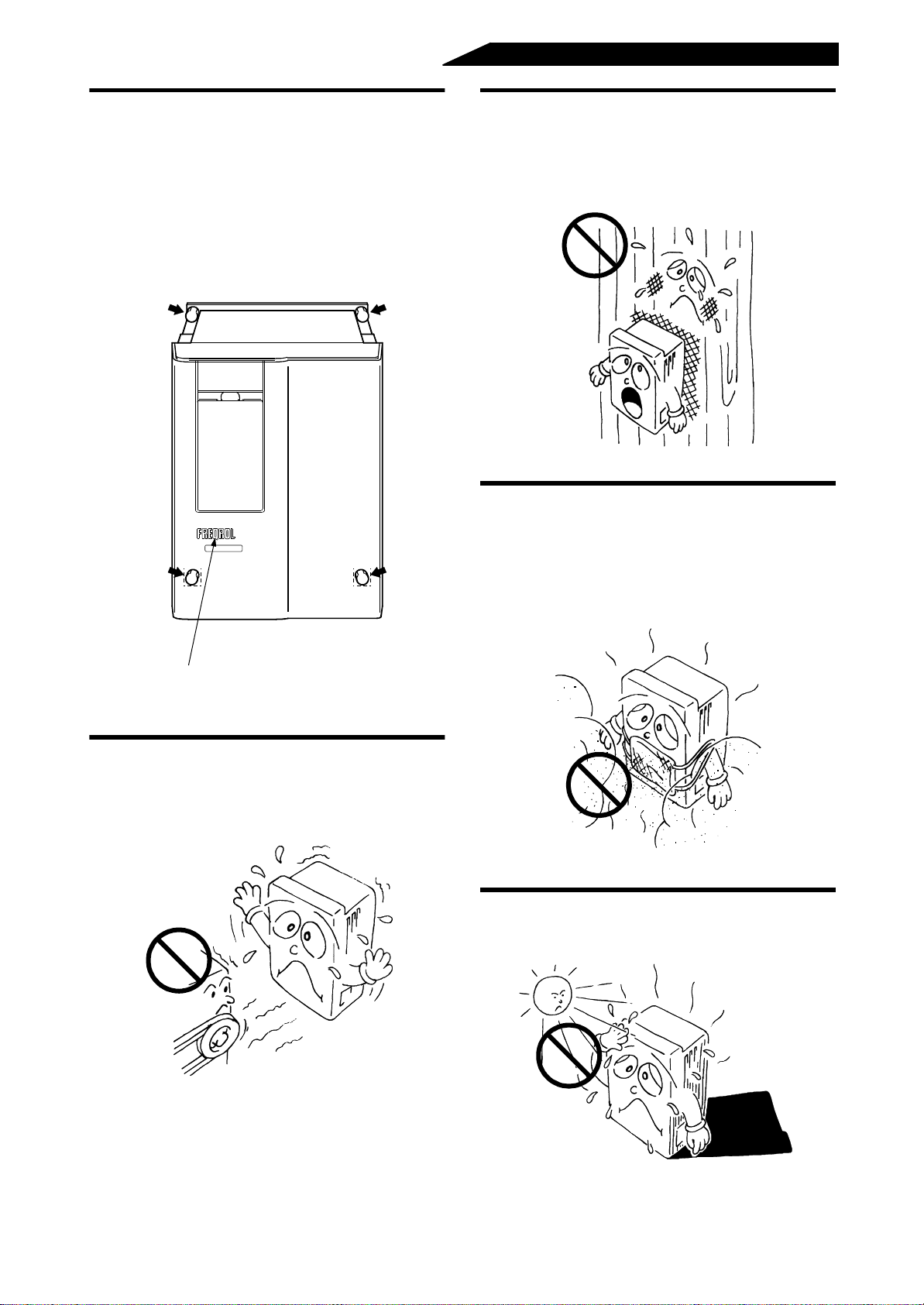
Bolt the unit sec u re ly and verticall y.
Install the un it on a non-combustible surface.
Install the high power factor converter on a surface
securely and vertically (so that the letters
FREQROL are located at the fro nt) with screws or
bolts.
Note: Hor izontal or side inst allation may cause the
high power factor converter to fail. Always
install the unit vertically.
Install the high power factor converter on a noncombustible. If it is installed directly on or near a
combustible, a fire may take place.
Avoid places where the equipment is subjected to
oil mist, flammable gases, fluff , dust, dirt, etc.
Install the unit in a clean place or inside an
“enclosure” which does no t accept any suspended
matter.
Located at front
Install the inverter where it is not subjected to
vibration.
Also take the vibration of a trolley, press, etc. into
consideration.
Avoid high temperature and high humidity.
Avoid direct sunlight, heat and humidity.
- 14 -
Page 24
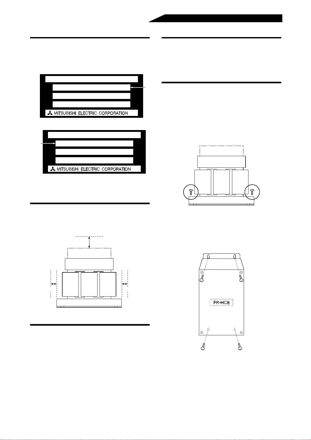
(2) Installation of the reactors 1, 2 and external box
Confirm th e types.
Note the types of the reactor 1 (FR-HCL01) and
reactor 2 (FR-HCL02) look alike in outline.
Reactor 1 (FR-HCL01)
AC REACTOR
TYPE FR-HCL01
BKO-CA
SERIAL
Reactor 2 (FR-HCL02)
AC REACTOR
(Note)
Note: For the reactor 1 (FR-HCL01) and reactor 2 (FR-
TYPE FR-HCL02
BKO-CA
SERIAL
HCL02), check the “TYPE” in the above rating
plates.
(Note)
Avoid places where the equipment is subjected to
oil mist, flammable gases, fluff , dust, dirt, etc.
Install the equipment in a clean place or protect
them from suspended matter.
Bolt the reactors securely and horizontally.
To prevent looseness, install the reactor 1 (FRHCL01) and reactor 2 (FR-HCL02) on a surface
securely and horizontally with screws or bolts.
Note:Avoid vertical or side installation and install
them on a mounting stand which can withstand
their weights.
Instructions for ambient temperatures
For adequate heat dissipation, leave sufficient
space around the reactor 1 (FR-HCL01) and
reactor 2 (FR-HCL02).
10cm or more
5cm or more5cm or more
Install the equipment on a non-combustible
surface.
Install the reactor 1 (FR-HCL01) an d reactor 2 (FRHCL02) on a non-combustible. Direct install ation on
a combustible may cause a fire.
Install the external box (FR-HCB) vertically.
Note:Install it vertically. Horizontal or side
installation may lead the external box to a
failure.
Note:Since the charged sections of the reactor 1,
reactor 2 and external box are uncovered, fully
protect them to prevent ground fault and
electric shock.
- 15 -
Page 25
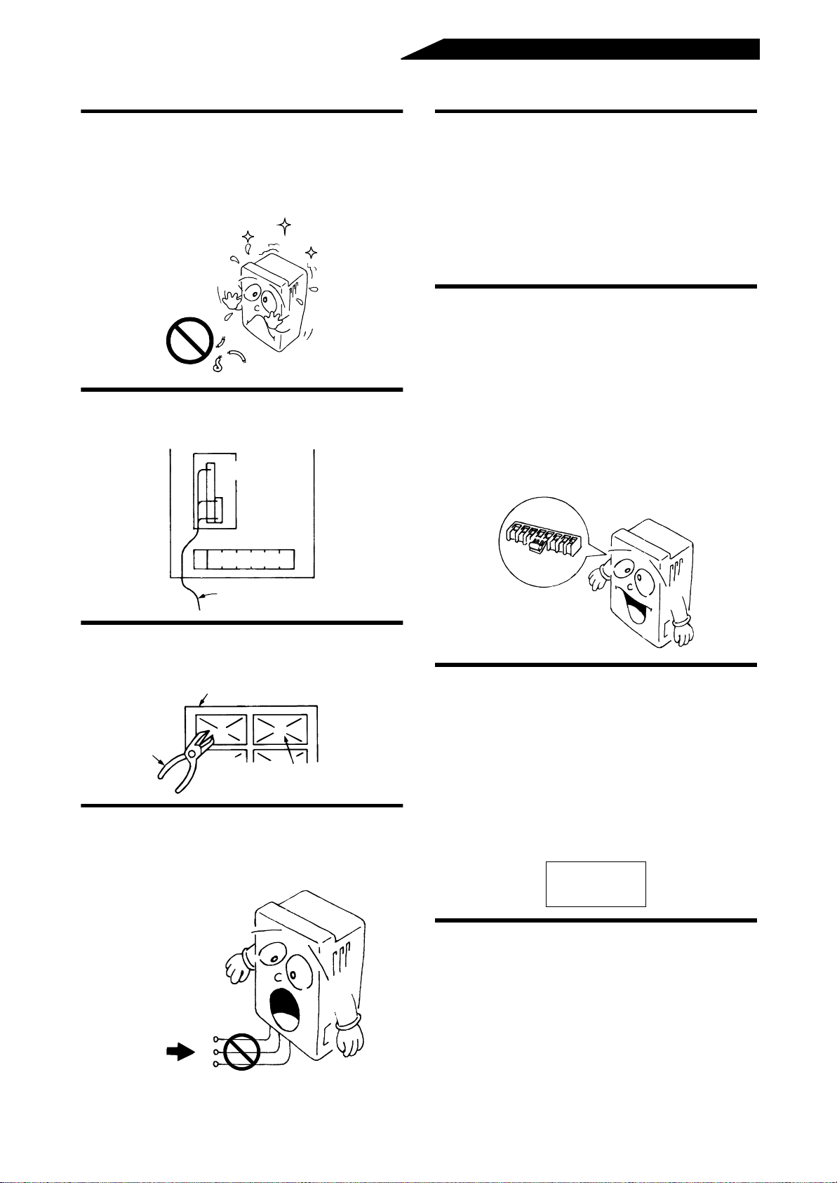
1.3.2 Wiring instructions
During wiring, d o no t l eave wire off-cut s i n t he
high power fact or converter and external bo x.
Wire offcuts will cause a mal func ti on, failure or fault.
The high power factor converter should always be
kept clean.
Wire offcuts, etc.
Use the space on the left-hand side of the main
circuit terminal block to run the control circuit
cable.
Control circuit terminal block
Before starting wiring or inspection, switch
power off, make sure that the converter LED
indicator has gone off, wait for at least 10
minutes after the charge lamp on the printed
circuit board has gone off.
For some short time after power-off, there is a
dangerous voltage in the capacitor. Start work
about 10 minutes after ensuring that the charge
lamp is off.
When the power supply voltage is special for the
high power factor converter (the rated input voltage
is exceeded), change the connection of the jumper
in the internal transformer. (FR-HC-H7.5K H15K,
H30K, H55K)
If the connection is not changed, the 400V class
high power factor converter may be heated,
resulting in fault or burnout.
For the FR-HC-H7.5K, change the connection of
the jumper in the interna l transform er in the externa l
box.
Main circuit terminal block
Cable
Cut off the wiring cover (protective bush)
windows using nippers or a cutter when
running the cables. (FR-HC-7.5K/H7.5K)
Wiring cover
Nippers
Cut off.
Protective bush
Do not apply a voltage directly to the alarm
output signal terminals (A, B, C).
Always apply a voltage via a relay coil, lamp, etc. to
these terminals.
380 to 460V
The cable size for connection to the control
2
circuit terminals should be 0.75mm
If the cable size used is 1.25mm
or less.
2
or more, the front
cover may expand, resulting in a co ntact fault of the
parameter unit. This fault is indicated by the
following message displayed on the parameter unit
and disables operation from the parameter unit.
Run the cables so that they do not occupy much of
the control box terminal block space.
Parameter unit display
PU to Inverter
comms. Error
Inv. Reset ON
Use shielded or twisted cables for connection to
the control circuit terminals.
Voltage
Run them away from the main and power circuits
(such as the 200V relay sequence circuit).
A
B
C
Note:Connect the sheath of the shielded cable to
terminal SD.
- 16 -
Page 26
1.3.3 Wiring of the main circuit
• The high power factor converter (FR-HC) is a high-power factor, low-noise inverter option unit designed for
use with the transistorized inverters (FR-HC compatible models) in accordance with the harmonic
suppression guidelines published by Ministry of Economy Trade and Industry (formerly Ministry of
International, Trade and Industry). This high power factor converter is used for the suppression of
harmonics to an input power supply.
• To comply with the harmonic suppression guidelines published by the MITI, the system needs to be
configured as indicated and make sure that terminals P and N are sacurely connected to terminals P and N
of the inverter. An incorrect connection will cause th e high power factor converter to display an alar m or to
be faulty or damaged.
• Refer to the inverter instruction manual on how to wire the system to suppress har monics to the input
power supply. Especially note the wiring distance and cable size.
(1) Cable, Crimping terminals etc.
The following table lists the cables and crimping terminals used for each of the devices of the High
power factor converter system and the torques for tightening the screws:
Cables
2
P, N
AWG *1mm
R4, S4,
T4
P, N
Type
Terminal
screw
size
Tightening
torque
·
m *3
N
Crimping
terminal *2
R4, S4,
T4
P, N
mm
R4, S4,
T4
FR-HC-7.5K M4 1 8-4 8-4 8 8 8 8 6 6
FR-HC-15K M6 4 22-6 22-6 22 22 4 4 16 16
FR-HC-30K M8 7 60-8 60-8 60 60 1/0 1/0 50 50
FR-HC-55K M12 24 150-12 150-12 150 150
MCM
300
MCM
300
FR-HC-H7.5K M4 1 3.5-4 3.5-4 3.5 3.5 12 12 4 4
FR-HC-H15K M6 4 8-6 8-6 8 8 8 8 10 10
FR-HC-H30K M6 4 22-6 22-6 22 22 4 4 25 25
FR-HC-H55K M8 7 60-8 60-8 60 60 1/0 1/0 50 50
PVC insulated
Cables
2 *
4
R4, S4,
T4
P, N
––
PVC insulated
Cables
2 *
4
Type
Terminal
screw
size
Tightening
torque
·
N
m *3
Crimping
terminal *2
R2, S2, T2R3, S3, T3R2, S2, T2R3, S3, T3R2, S2, T2R3, S3, T3R2, S2, T2R3, S3,
mm
Cables
2
AWG *1mm
FR-HCB-7.5K M5 2 8-5 8-5 8 8 8 8 6 6
FR-HCB-15K M5 2 22-5 22-5 22 22 4 4 16 16
FR-HCB-30K M6 4 60-6 60-6 60 60 1/0 1/0 50 50
FR-HCB-55K M8 7 150-8 150-8 150 150
MCM
300
MCM
300
––
FR-HCB-H7.5K M5 2 3.5-5 3.5-5 3.5 3.5 12 12 4 4
FR-HCB-H15K M5 2 8-5 8-5 8 8 8 8 10 10
FR-HCB-H30K M5 2 22-5 22-5 22 22 4 4 25 25
FR-HCB-H55K M8 7 60-8 60-8 60 6 0 1/0 1/0 50 50
PVC insulated
Cables
2 *
R, S, T
4
R2, S2,
Type
Terminal
screw
size
Tightening
torque
N
·
m *3
terminal *2
R, S, T
Crimping
R2, S2,
T2
R, S, T
mm
2
R2, S2,
T2
Cables
AWG *1mm
R, S, T
R2, S2,
T2
FR-HCL01-7.5K M5 2 8-5 8-5 8 8 8 8 6 6
FR-HCL01-15K M6 4 22-6 22-6 22 22 4 4 16 16
FR-HCL01-30K M8 7 60-8 60-8 60 60 1/0 1/0 50 50
FR-HCL01-55K M12 24 150-12 150-12 150 150
MCM
300
MCM
300
––
FR-HCL01-H7.5K M4 1 3.5-4 3.5-4 3.5 3.5 12 12 4 4
FR-HCL01-H15K M5 2 8-5 8-5 8 8 8 8 10 10
FR-HCL01-H30K M6 4 22-6 22-6 22 22 4 4 25 25
FR-HCL01-H55K M8 7 60-8 60-8 60 60 1/0 1/0 50 50
T3
T2
- 17 -
Page 27
Cables PVC insulated Cables
2
AWG *1mm
2 *
Type
Terminal
screw
size
Tightening
torque
·
N
m *3
Crimping
terminal *2
R3, S3, T3R4, S4, T4R3, S3, T3R4, S4, T4R3, S3, T3R4, S4, T4R3, S3, T3R4, S4,
mm
FR-HCL02-7.5K M5 2 8-5 8-5 8 8 8 8 6 6
FR-HCL02-15K M6 4 22-6 22-6 22 22 4 4 16 16
FR-HCL02-30K M8 7 60-8 60-8 60 60 1/0 1/0 50 50
FR-HCL02-55K M12 24 150-12 150-12 150 150
MCM
300
MCM
300
––
FR-HCL02-H7.5K M4 1 3.5-4 3.5-4 3.5 3.5 12 12 4 4
FR-HCL02-H15K M5 2 8-5 8-5 8 8 8 8 10 10
FR-HCL02-H30K M6 4 22-6 22-6 22 22 4 4 25 25
FR-HCL02-H55K M8 7 60-8 60-8 60 60 1/0 1/0 50 50
Note: *1.The cable used should be 75°C copper cables.
*2.Use the UL approved round crimping terminals. Crimp the terminals with the crimping tool
recommended by the terminal manufacturer.
*3.Tighten the terminal screws to the specified torques. Undertigtening can cause a short or misoperation.
Overtigtening can cause the screws and unit to be damaged, resulting in a short or misoperation.
*4.This column is for Low Voltage Directive.
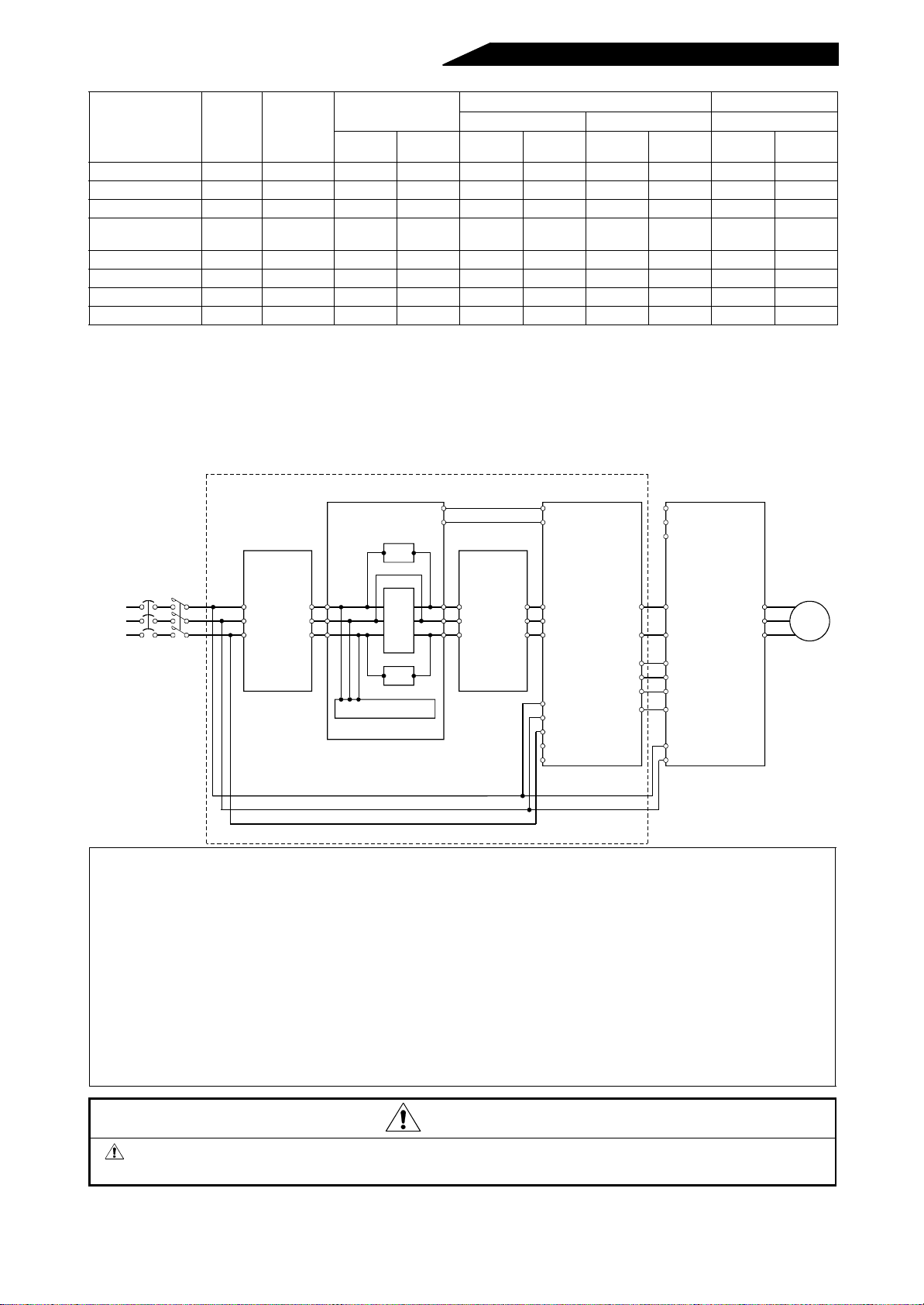
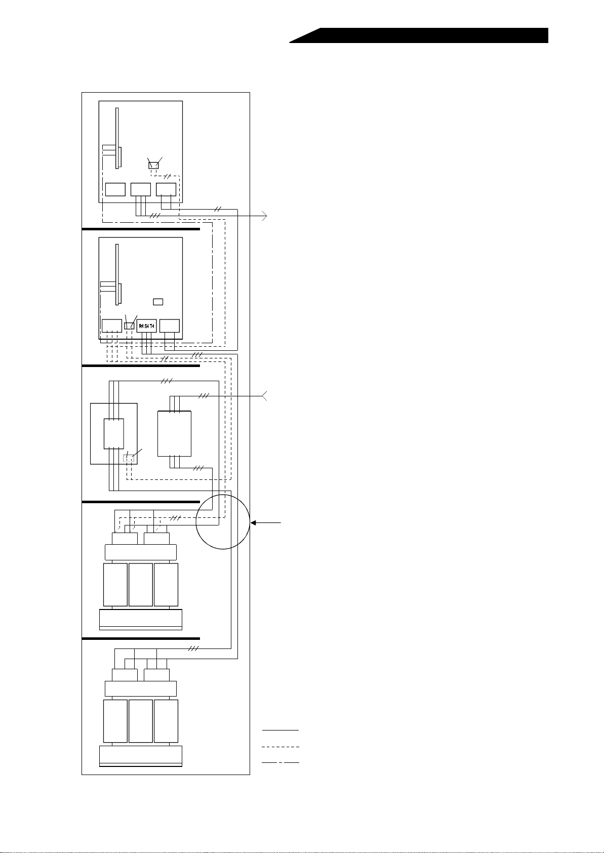
(2) Wiring example (FR-A500 series)
The wiring method varies with the inverter series.
Reactor 1
(FR-HCL01)
External box
(FR-HCB)
Resistor
MC1
MC2
Reactor 2
(FR-HCL02)
High power factor converter
(FR-HC)
MC1
MC2
Inverter
(FR-A500 series)
R
(Note 4)
S
T
4
T4
Power
supply
NFB MC
1)
R
S
T
R2
S2
T2
2)
R2
S2
T2
MC
Resistor
Filter capacitor
3) 4) 5)
R3
S3
T3
R3
S3
T3
R4
S4
T4
6)
S4
R
S
T
R1
S1
R4
T4
RDY
RSO
Y1 or Y2
(Note 8)
SE
P
P
(Note 9)
N
N
X10
(Note 5)
RES
X11
(Note 5)
SD
R1
(Note 7)
S1
7)
Note: 1.Use care to minimize the wiring distance between respective terminals.
2.Before starting wiring, cover the top ventilation hole to prevent wire offcuts from entering.
3.Use the ground terminal to ground the equipment securely.
4.Keep the inverter’s power input terminals R, S, T open. The i nverter will be damaged if they are
connected accidentall y. Also, opposite polar ity of term inals P, N will damage the high power factor
converter and inverter.
5.The terminals used with the X10, X11 signals require their functions to be set. (Refer to the inverter
instruction manual for details.)
6.Match the power supply phases before connecting terminals R4, S4, T4 and terminals R, S, T.
7.A different power supply may be supplied to terminals R1 and S1.
8.Keep the high power factor converter’s terminals R1, S1 unconnected.
9.Do not insert the NFB between terminals P-N (P-P, N-N).
10.The R, S , T terminals of the high pow er factor converter (FR-HC) must be connected to the po w er supply.
Running the inverter without connecting the terminals to the power supply will damage the high power
factor converter (FR-HC).
U
Motor
V
W
CAUTION
Confirm the connection sequence of the reactors 1 and 2. Incorrect connection will make
them abnormally hot.
- 18 -
Page 28

1) Wiring the power supply and reactor 1
Power
supply
NFB
MC
Reactor 1
R2
R
S2
S
T2
T
Reactor 1
RR2S S2T T2
RS T
Power supply
R
Power
supply
ST
FR-HCL01-55K appearance
(Note 2)
The cable size is dependent on the capacity of the high power factor converter. (Refer to page 17.)
Note: 1.Use the magnetic contactor (MC) and reactor 1 which match the high power factor converter capacity.
(Refer to page 62.)
2.Note that the FR-HCL01-55K is different in outline and terminal positions.
2) Wiring the reactor 1 and external box
Reactor 1 External box
R
R2
S
S2
T
T2
R2
S2
T2
R3
S3
T3
Reactor 1
Overall wiring distance: Within 10m
Transtormer
Capacitor
S2
R2 T2
Magnetic
Resistor
contactor
S3R3 T3
FR-HCL02
MC1.MC2
FR-HC
Resistor
Terminal block
Note: 1.The cable size is dependent on the capacity of the external box. (Refer to page 17.)
2.The reactor generates heat. When installing the reactor, exercise care not to heat the external box.
3.Run the cables to keep the reactor untouched by the sheaths of the cables.
- 19 -
Page 29

3) Wiring the external box and reactor 2
r
(Overall wiring distance should be not more than 10m.)
External box Reactor 2
R3
R2
S2
T2
S3
T3
R3
R4
S3
S4
T3
T4
Overall wiring distance: Within 10m
Reactor 2
Resistor
Note: The cable size is dependent on the capacity of the reactor. (Refer to page 17.)
4) Wiring the reactor 2 and high power factor converter
(Overall wiring distance should be not more than 10m.)
Power supply
FR-HCL01
Capacitor
S2
R2 T2
Magnetic
contactor
S3R3 T3
Transtormer
Resistor
Terminal block
MC1.MC2
FR-HC
Reactor 2
R4
R3
S4
S3
T4
T3
High power factor converte
R4
S4
T4PN
R3 R4 S3 S4 T3 T4
Reactor 2
High power factor converter
High power
factor converter
Screw size
M4
R1 S1
RSTR4S4T4
PN
Charge lamp
(yellow)
Note: The cable size is dependent on the capacity of the reactor. (Refer to page 17.)
5) Example of how to wire the high power factor converter and inverter (FR-A500 series)
These units should be connected to transmit commands from the high power factor converter to the
inverter securely.
The cable size varies with the inverter series. Refer to the inverter instruction manual for wiring
instructions.
(Overall wiring distance should be not more than 50m.)
High power factor converter
P
N
RDY
Control
circuit
RSO
Y1 or Y2
SE
P
N
X10
RES
X11
SD
Inverter
(Note 3)
Cable size: 0.75 to 2 mm
2
- 20 -
Page 30

Note: 1.The high power factor converter (FR-HC) operates as a common conver ter. Use terminals P, N to
r
t
connect it with the inverter. Always keep the inverter’s power input terminals R, S, T open. If they
are connected accidentally, the inverter will be damaged. Opposite po larity of terminals P, N will
damage the inverter and high power factor converter.
2.The size of the cables for connecti on of terminals P, N should be the same as that use d in the
power supply side of the inverter. (Refer to the inverter instruction manual.)
3.Refer to the inverter instruction manual for the invert er terminal to be c onne cted to termi na l R DY of
the high power factor converter.
4.Do not insert the NFB between terminals P-N (P-P, N-N).
6) Wiring the reactor 1 and high power factor converter
Supply power to the power detecting terminals (R, S, T) independently of the main circuit wiring.
High power factor converte
contro l ci rcuitReactor 1
R
S
T
R
S
T
Power
supply
Reactor 1
R
S
T
High power factor converter
control circuit terminals
S
R
T
Overall wiring distance: Within 10m
Cable size: 1.25mm
2
Note: 1.Ter minals R, S, T of the high power factor converter (FR-HC) are control terminals designed to
detect power supply phases. Be fore wiring, it is necessar y to match the phases of ter minals R4,
S4, T4 with those of terminals R, S, T. If wiring is inc orrect, the high power factor converter (F RHC) will not operate properly.
2.The R, S, T terminals of the high power factor converter (FR-HC) must be connected to the power
supply.
Running the inverter without c onnecting the terminals to the power supply will damag e the high
power factor con verter (FR-HC).
7) Wiring the power supply and inverter
Supply power to the inverter independently of the high power factor converter (FR-HC).
Terminal block for control circui
Pull out.
NFB
Power
supply
Cable size:0.75 to 2mm
Inverter control power supply
R1
S1
2
1) Loosen the upper screws.
2) Remove the lower screws.
3) Pull out the jumpers toward
you and remove.
4) Conncet the cables of the
other control circuit power
supply to the lower
terminals (R1, S1).
5) Tighten the upper
screws without fail.
Note: 1.Remove the jumpers across terminals R-R1 and S-S1 of the inverter control circuit.
2.Always connect the power supply to the inver te r wh ic h has the alternate power supply inp ut terminals
R1, S1. Power for the inverter’s control power and large-capacity cooling fan (200V 15K or more/
400V 11K or more) will be supplied. Otherwise the inverter may come to an alarm stop or be
damaged. Refer to the inverter instruction manual to check whether the inverter has the alternate
power supply input terminals or not.
- 21 -
Page 31

8) Wiring the external box and high power factor converter
Power supply
FR-HCL01
Capacitor
S2
R2 T2
S3R3 T3
FR-HCL02
External box
MC1
MC2
Cable size: 0.75 to 2mm
High power factor
converter
MC1
MC2
2
Resistor Magnetic contactor
Transformer
Resistor
Terminal
block
MC1.MC2
High power factor converter
Control circuit
terminal block
RSTR4S4T4
Overall wiring distance:
Within 10m
Screw size
M4
R1 S1
PN
Note:Ter minals MC1, MC2 of the high power factor converter provide contro l signals for the inrush cur rent
control circuit within the exter nal box. Always connect these ter minals with the external box. Otherwis e,
the external box’s internal circuit will be damaged.
Notes for grounding
• The high power factor converter lea ks cur rent. To prevent an electric shock, always
ground the converter before starting operation (200V class: class D grounding,
grounding resistance 1 00 maximum, 400V class: class C grounding, grounding
resistance 10 maximum).
Ω
Ω
• To ground the hi gh power factor converter, use the exclusive ground termina l. (Do
not use the screws in the casing, chassis, etc.)
• Use the thickest and shortest possible ground
cable that is equal to, or larger than the size
indicated in the right table. Ground the high
power factor converter at a point ne arest to itself
and the inverter.
High power factor
converter capacity
Ground cable size
200V class 400V class
7.5kW 5.5 3.5
15kW 14 8
30kW 22 14
55kW 38 22
(Unit:mm2)
Grounding
- 22 -
Page 32
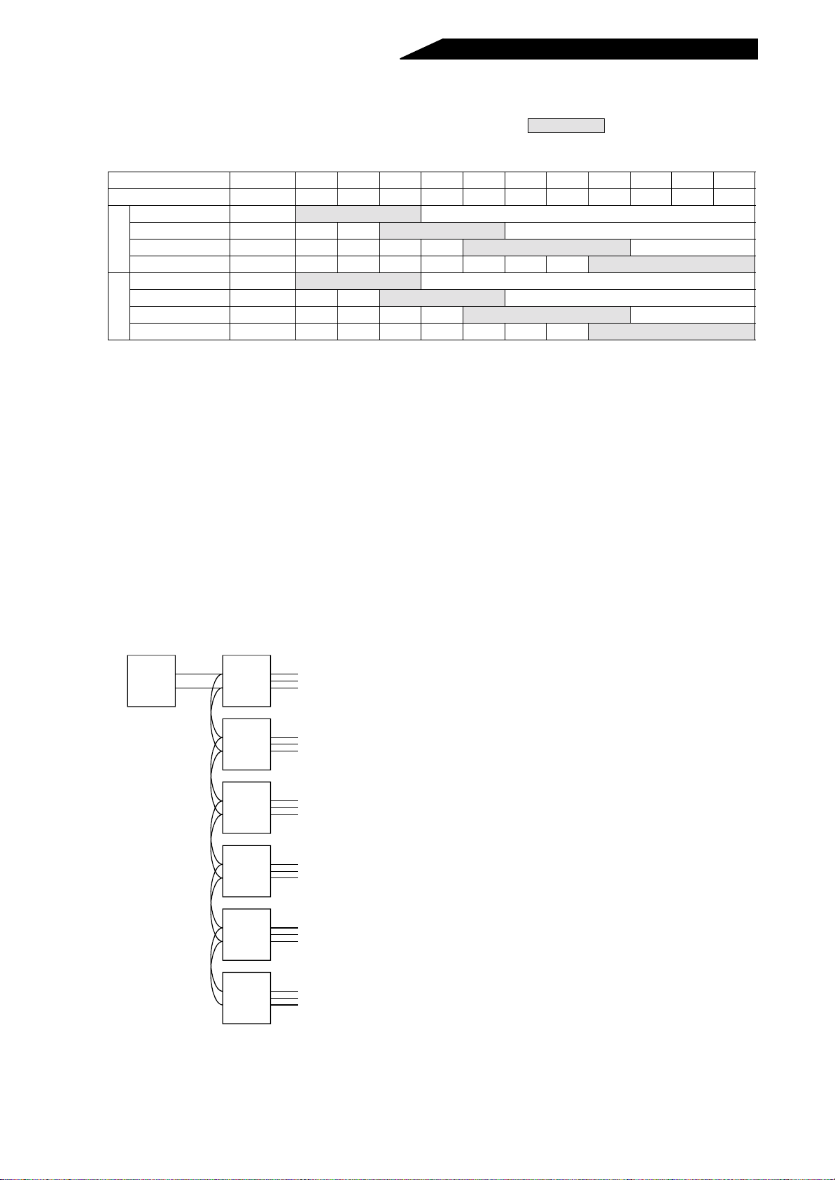
(3) Application of the high power factor converter and inverter
1) When one inverter is connected to the hig h power factor converter, the capacities of the inverters that
may be connected are as listed in the following selection table. : indicates that the high
power factor converter and inverter may be used together. –: indicates that they cannot be used
together. (Note)
Motor capacity (kW) 2.2 or less 3.7 5.5 7.5 11 15 18.5 22 30 37 45 55
Inverter capacity (K) 2.2 or less 3.7 5.5 7.5 11 15 18.5 22 30 37 45 55
FR-HC-7.5K –
2
FR-HC-15K –––
0
0
FR-HC-30K – ––––
V
FR-HC-55K – –––––––
FR-HC-H7.5K –
4
FR-HC-H15K –––
0
0
FR-HC-H30K – ––––
V
FR-HC-H55K – –––––––
Outside application range
Outside application range
Outside application range
Outside application range
Outside application range
Outside application range
Note: When the invert er connected has a capacity less tha n in the application range, the high power
factor converter may be used as a common conver ter or regenerative converter, but its capability
to suppress power harmonics will reduce.
(4) Connection of more than one inverter to the high power factor conve rter
Up to six inverters may be connected to one high power factor converter. (Do not connect seven or more
inverters.) The capacity of the high power factor converter should always be higher than the sum of
those of the inverters connecte d. Also, one inverter connected should have a capacity more than half of
the high power factor converter capacity.
Note: Note that if the sum of the inver ter capacities is less than half of the high power factor converter
capacity, the high power factor converter may be used as a common conver ter or regenerative
converter, but its capability to suppress power harmonics will decrease.
1)For connection of more than one inverter, select the cable size carefully beca use the inverter termin als
P, N will be wired us ing junction ter mina ls or jumpers. Select the cable size so that inverter capacities
are added in order, beginning with the farthest inverter.
2)For connection of more than one inverter, connect them in sequence of larger capacities.
3)Specific example
FR-HC
55K
P
N
A520
30K
P
A520
15K
N
P
A520
5.5K
N
P
A520
2.2K
N
First: 125mm
Second: 15+5.5+2.2+1.5+0.75=24.95K
Hence, capacity is 30K, so 50mm
Third: 5.5+2.2+1.5+0. 75=9.95K
Hence, capacity is 11K, so 14mm
Fourth: 2.2+1.5+0.75=4.45K
Hence, capacity is 5.5K, so 5.5mm
2
cable from FR-HC capacity
2
cable is selected.
2
cable is selected.
2
cable is selected.
P
A520
1.5K
N
P
A520
0.75K
N
Fifth: 1.5+0.75=2.25K
Hence, capacity is 2.2K, so 2mm
2
Sixth: 2mm
cable from 0.75K
2
cable is selected.
Note: When the FR-E500, FR-A024 series inverters are connected to the high power
factor converter (FR-HC-7.5K), at least one of the inverter connected is
required t o be at least half the ratin g of the high power factor rating. In this
case, at least one of the inverter connected is 3.7K or greater.
- 23 -
Page 33
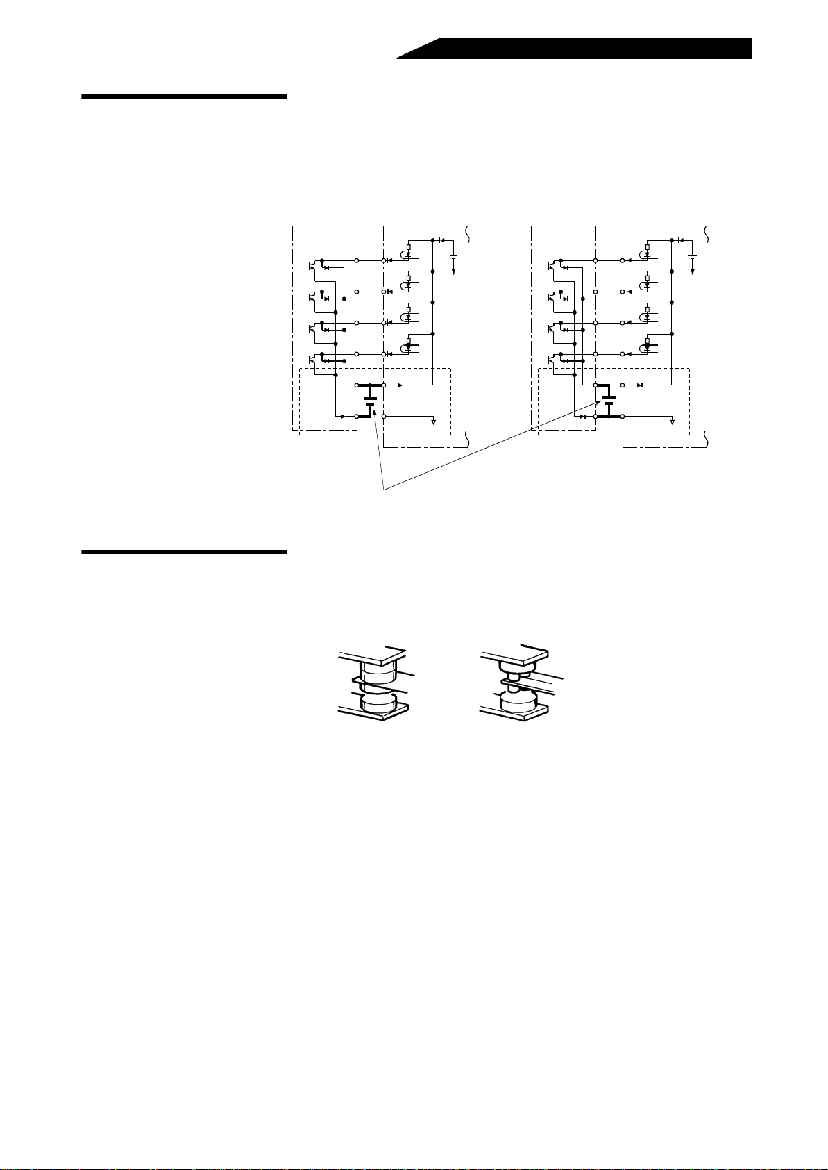
(5) Where the power supply is special (rated input voltage is exceeded) for the 400V class high
power factor converters (FR-HC-H15K, H30K, H55K, FR-HCB-H7.5K)
Change the connection of the j um per to the internal transfor me r a ccor ding to t he op erating power supply
voltage. For the FR-HC-H7.5K, change the connection of the internal transformer inside the external
box.
Operating power supply voltage range vs. jumper position
Jumper Position
323V(380V-15%)
V1
456V(415V+10%)
342V(380V-15%)
V2
484V(440V+10%)
391V(460V-15%)
V3
506V(460V+10%)
Operating Power Supply Voltage
50Hz 60Hz
to
to
to
As on the left
342V(380V-10%)
to
506V(460V+10%)
As on the left
Remarks
Factory setting
Note: Change the jumper position acco rding to the operatin g power supply. Otherwise the high power
factor converter will be heated and may become faulty or burn out.
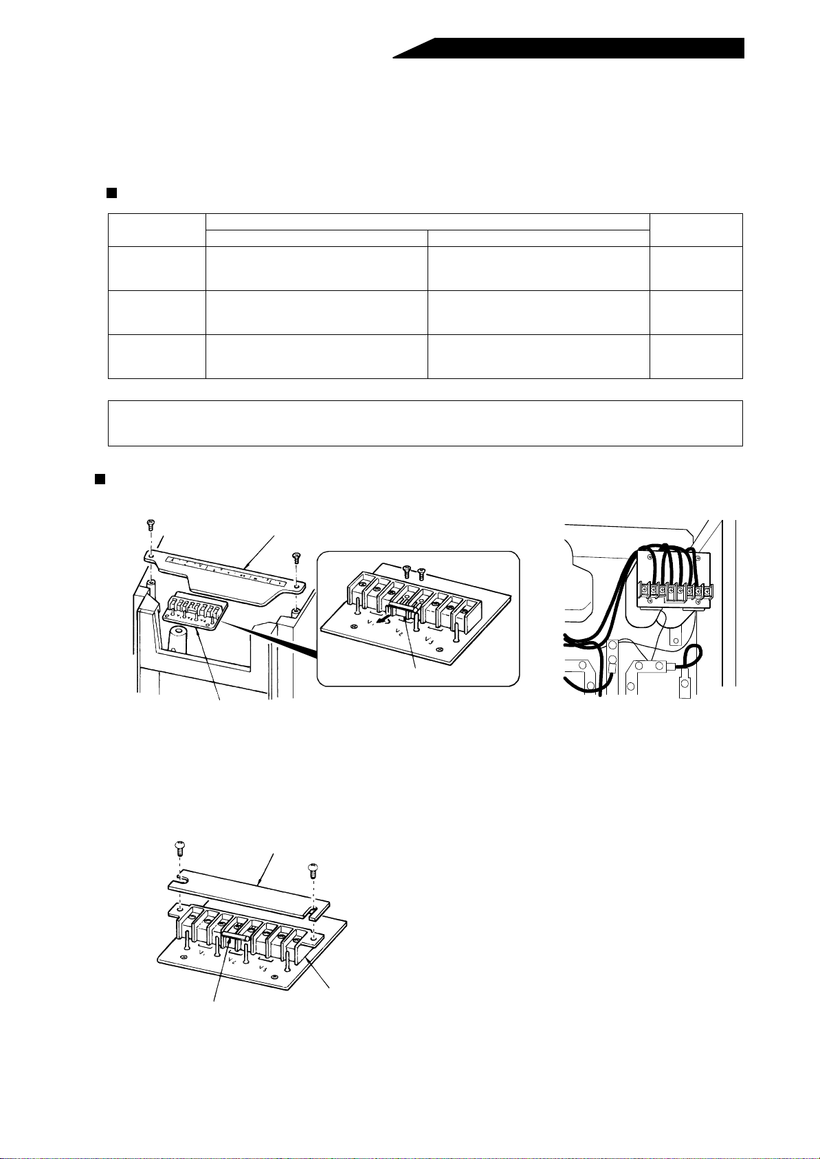
Changing the jumper position
• Model: . . . . FR-HC-H15K, FR-HCB-H7.5K
Terminal symbol cover
Pull out.
Jumper
Transformer terminal block
Appearance of
FR-HCB-H7.5K
1) Remove the mounting screws of the terminal symbol cover and remove the cover.
2) This reveals the termi nal block of the inter nal transform er. After removing the screws from the jumper in
the terminal block, reconnect the jumper in accordance with the operating voltage in the above table.
• Model: . . . . FR-HC-H30K, H55K
Terminal cover
1) Remove the terminal cover of the internal
transformer located under the main circuit
terminal block (R, S, T).
2) Remove the screws from the jumper in the
terminal block, and reconnect the jumper.
Jumper
Transformer terminal block
- 24 -
Page 34
(6) Installation and wiring example
<Vertical mounting>
Inverter
R1
S1
N P
U V W
R S T
MC
MC1
HCB
MC1
Converter
(FR-HC)
MC2
MC2
N P
Motor
<Instructions>
1) Leave clearances of at least 10cm above
and below and 5cm o n the left and right
side of each unit.
2) Up to six cables may be bundled.
3) Install par titions to shut off heat given to
the upper units.
4) The reactors generate heat. Run cables
away from them.
5) When the installation place has enough
space, it is recommended to install the
units side by side.
Power supply
NFB
HCL01
HCL02
(Note 4)
Main circuit
High-voltage control circuit
Low-voltage control circuit
- 25 -
Page 35
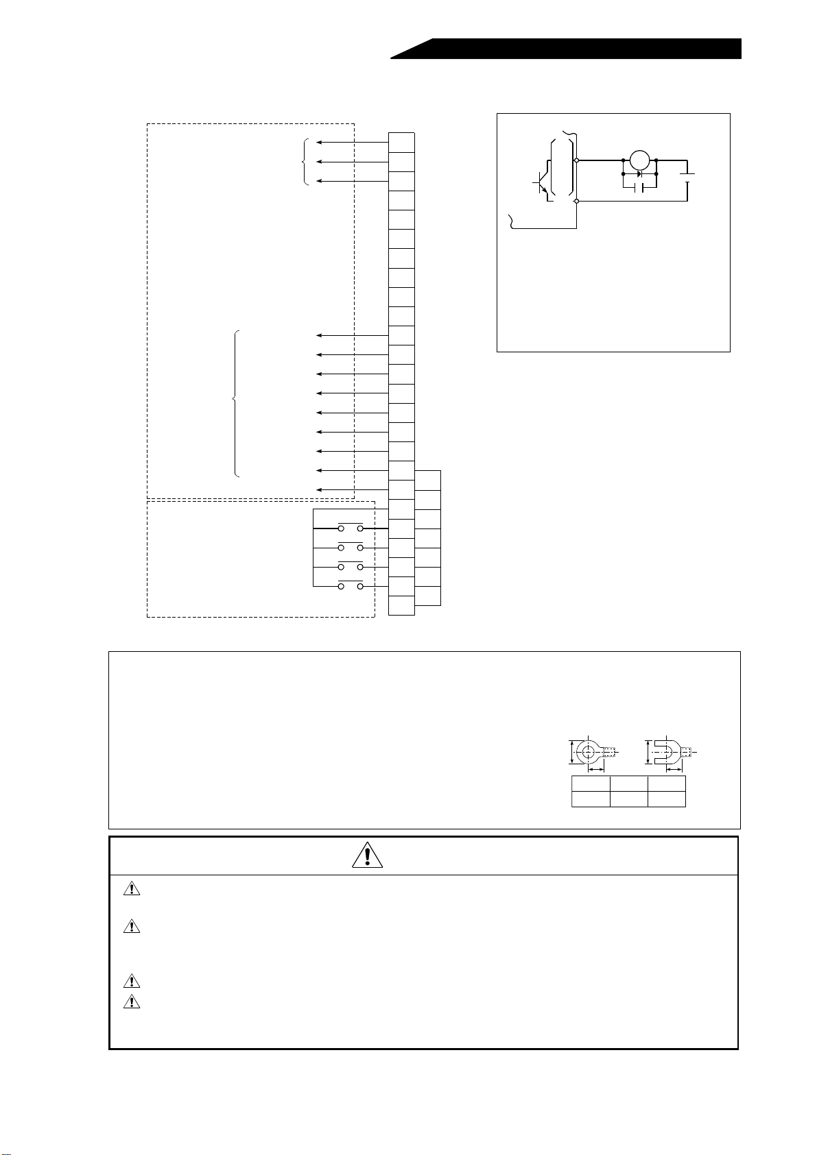
1.3.4 Wiring of the control circuit
)
)
)
)
)
)
Control input signals (voltage input disabled)
(Note)
r
y
r
C
3
(For terminal block functions, refer to “Terminals” on page 58.)
Output signals
Alarm output
(1 change-over contact output)
Open collector
output common
Multi-purpose
output terminal
Multi-purpose
output terminal
Open collector
outputs
Overload alarm
Converter reset
Converter operating
Inverter operation
Meter connection
common
Meter connection
Contact input common
Monitor switching
Monitor switching
Converter stop
External transistor common
enable
Reset
(NC)
(NC)
(NC)
(NC)
(NC)
(NC)
(NC)
SE
Y2
Y1
OL
RSO
CVO
RDY
SD
FM
SD
X2
X1
SOF
RES
PC
A
B
C
High
power
factor
converter
RDY
CVO
RSO
OL
V1
Y2
SE
RA
Powe
suppl
24V o
12VD
Note: A voltage applied in the wrong
direction will damage the high
power factor converter. Beware
of miswiring such as the
direction of diode connection.
(NC)
(NC
(NC
(NC
(NC
(NC
(NC
Note: 1.Terminals SD and SE are common to the I/O signals and are isolated from each other. Do not
earth (ground) .
2.Use shielded or twisted cables for connection to the control circuit terminals and run them
away from the main and power circuits (including the 200V relay sequence circuit).
3.Since the control circuit input signals are micro currents, use two parallel micro signal contacts
or a twin contact to prevent a contact fault.
4.Keep the free termina ls ( NC) unc on nected. Otherwise, the high
power factor converter may become faulty.
5.When connecting two crimping terminals to one of the control
circuit terminals, round or square open-ended crimping terminals
of the size as shown on t he r igh t s hou ld be use d b ack to ba ck.
Do not use the free terminals (NC) of the control circuit. Using them will lead to the
failure of the high power factor converter and inverter.
Steep distortion or sinking in power may cause the reactor 2 (FR-HCL02) to generate
unusual noise. This phenomenon occurs due to a power fault and is not attributable to
a damaged high power factor converter (FR-HC).
When the load is light, harmonic suppression effects will decrease.
Be sure to connect terminal RDY of the FR-HC to the X10 or MRS signal assigned
terminal of the inverter, and connect terminal SE of the FR-HC to terminal SD of the
inverter. Without proper connecting, FR-HC will be damaged.
B
FF
Nominal
1.25-3
Note: Round crimping terminal V1.25-MS
(Japan Solderless Terminal)
B(mm)
6.4 or less
B
F(mm)
53 or more
CAUTION
- 26 -
Page 36
Using the PC terminal
This termi nal is used to connect transistor output (open coll ector output)
such as a pr ogrammable controller (P C). Connecting the external power
supply common for transistor outpu t to the PC terminal prevents a faulty
operation caused by a sneak current.
(The power supply voltage of the PC terminal should be 24VDC.)
Instruction for contact inputs
<Correct connection>
AY40 transistor
output module
10
1
2
3
4
9
DC
24V
DC
x2
x1
SOF
RES
PC
SD
High power factor converter
24V
(SD)
AY40 transistor
output module
<Incorrect connection>
1
x2
2
x1
3
SOF
4
RES
9
PC
10
DC
SD
24V
High power factor converter
DC
24V
(SD)
The AY40 module requires a 24VDC power supply.
Since input signals to the control circuit are at a low level, use two parallel
micro signal contacts or twin contact for contact inputs to prevent a contact
fault.
Micro signal contacts
- 27 -
Twin contact
Page 37
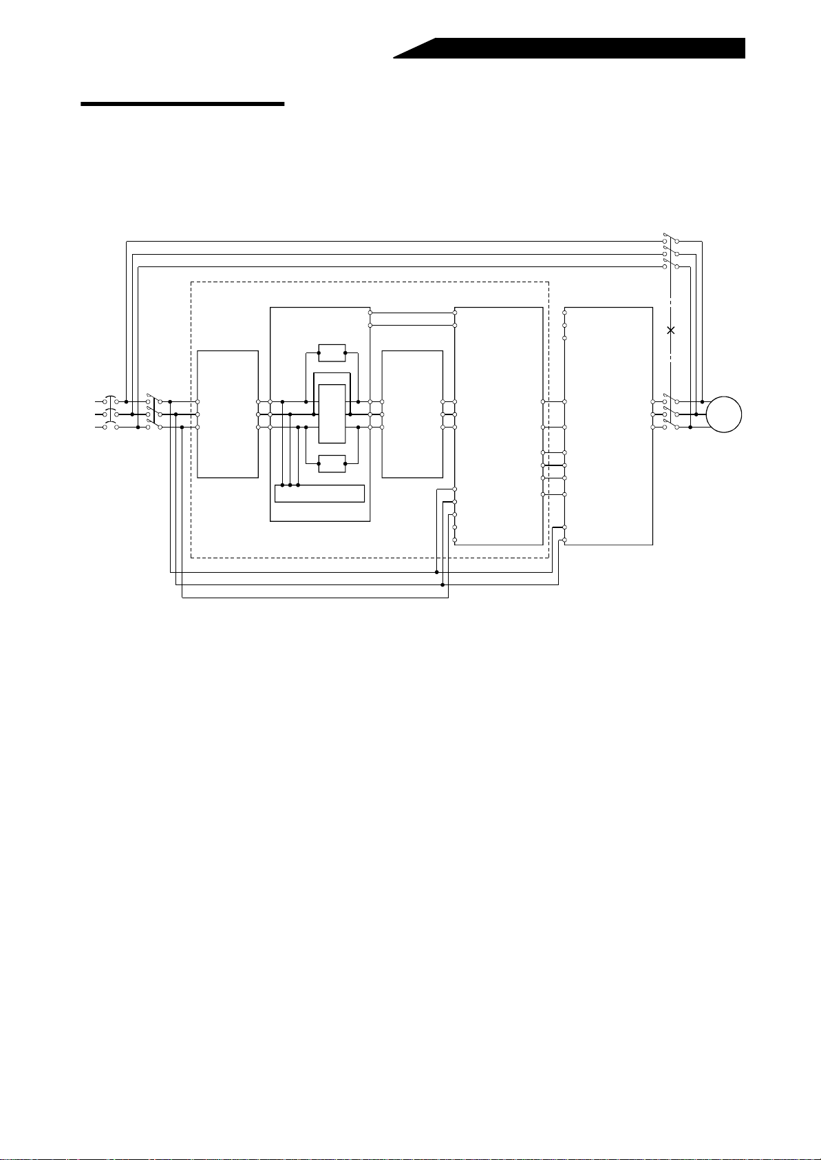
Wiring example for commercial
power supply-inverter switchover
• Complicated sequence circuit for commercial power supply-inverter
switch-over
The following example shows wiring for connection of a commercial
power supply. (FR-A500 series) When making connection, always
provide interlocks between magnetic contactors MC2 and MC3:
MC2
NFB MC1
Power supply
Reactor 1
(FR-HCL01)
R
S
T
R2
S2
T2
External box
(FR-HCB)
R2
S2
T2
Filter capacitor
Resistor
MC
Resistor
MC1
MC2
R3
S3
T3
Reactor 2
(FR-HCL02)
R3
S3
T3
converter (FR-HC)
MC1
MC2
R4
S4
S4
T4
R
S
T
R1
S1
High power fa ct or
R4
T4
RDY
RSO
Y1 or Y2
SE
(Note)
N
Inverter
(FR-A500 series)
R
S
T
PP
N
X10
RES
X11
SD
R1
S1
MC3
U
V
W
Motor
Note: Keep the high power factor converter’s terminals R1, S1 unconnected.
- 28 -
Page 38

2. PARAMETERS
This chapter presents details on the “parameters” of this
product.
Always read the precautions, etc. before starting use.
2
2.1 PARAMETER UNIT.................................................................................... 29
2.2 PARAMETER FUNCTION DETAILS .......................................................... 31
2.3 HELP FUNCTIONS........................ ............................................ .. .............. 40
2.4 CONVERTER RESET................................................................................ 43
Page 39
2.1 PARAMETER UNIT
g
The parameter unit (FR-PU02E-1) is installed directly to the high power factor converter or
connected to it by the cable (FR-CBL) to allow parameters to be set and data to be
monitored. Note that as compared to the inverter, there are restrictions on functions. In this
manual, the parameter unit may be referred to as the PU.
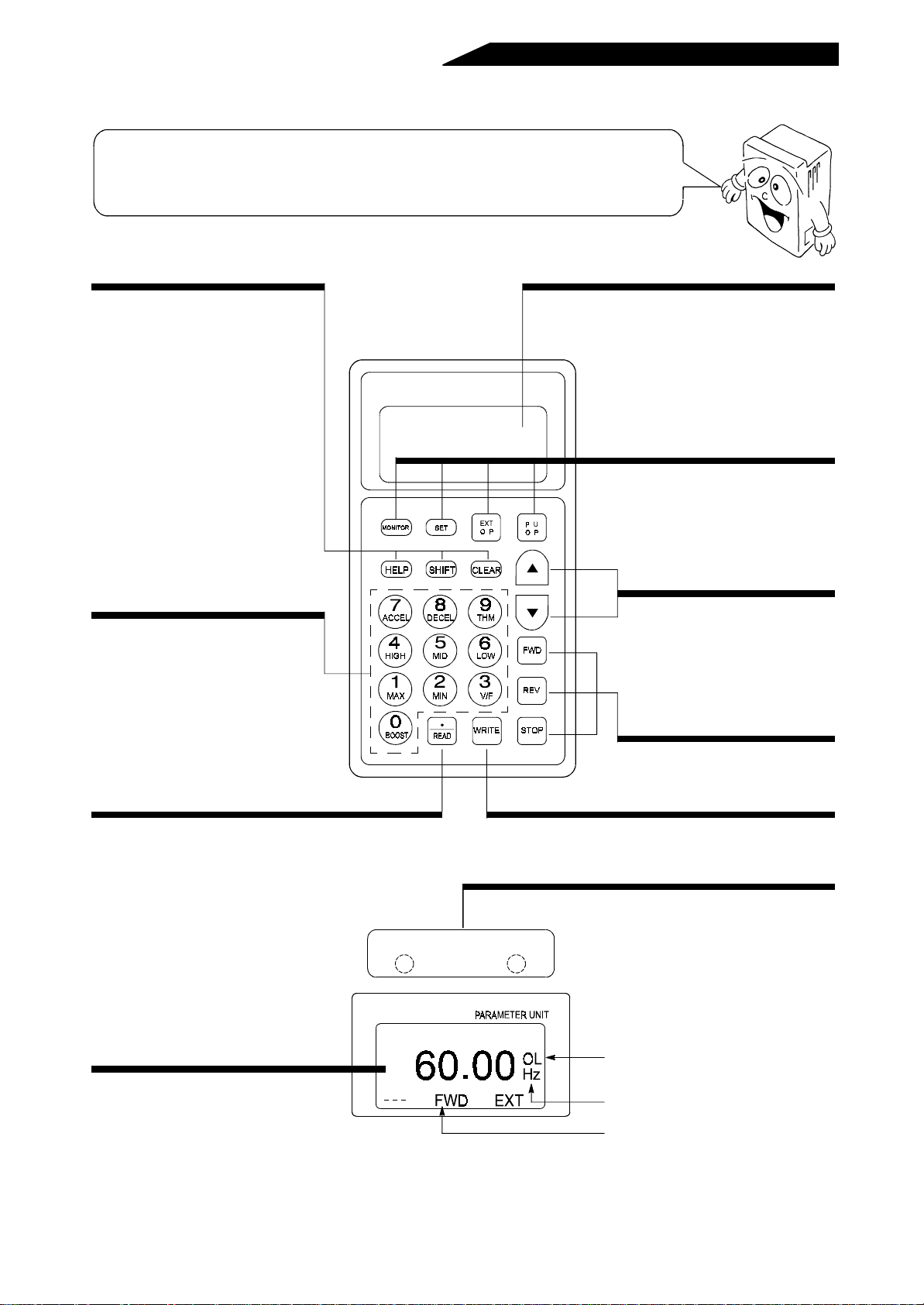
2.1.1 Structure of the parameter unit
Help key
• Used to call the help selection
screen.
• Note that there are restrictions.
Clear key
• Used to clear a set value entered.
• Used to return to the help
selection screen when you have
selected an invalid help item.
Shift key
• Used to shift to the next item in
the setting or monitoring mode.
Numeral keys
• Used to enter the parameter
number and set value.
FR-PU02E
PARAMETER UNIT
-1
Display
• Shows the monitor screen, etc.
Mode selecton keys
• Used to select the setting mode
and monitoring mode. The “EXT
OP” and “PU OP” keys are invalid.
Frequency change ke ys
• On the monitoring, parameter or
help item selection screen, these
keys are used to move the cursor.
Hold down the SHIFT key and
press either of these keys to
advance or return the display
screen one page.
Read key
• Used also as a decimal point key.
• Acts as a key to select or read any of various functions.
PU main monitor
• Three different monitors can be select ed
in sequence with the [SHIFT] key.
POWER ALARM
FR-PU02E
-1
Operation command key s
• Invalid.
Write key
• Used to write a set value in the
setting mode, etc.
Converter LED display
• POWER (yellow) indicates whether
power is supplied or not and ALARM
(red) indicates whether alarm output is
provided or not.
Overload signal detecting
indication
Display unit
Indicates the driving (FWD) or
re
enerative (RV) mode.
- 29 -
Page 40
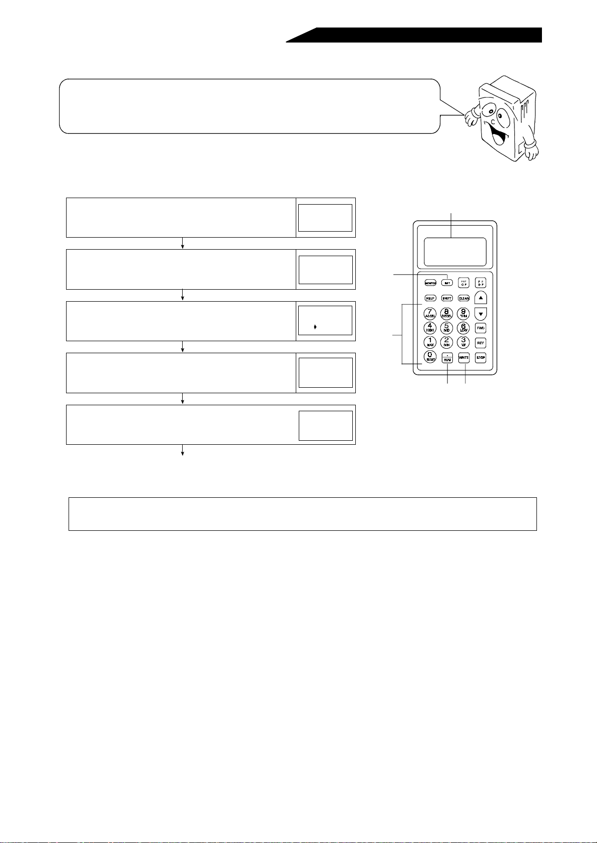
2.1.2 Setting and changing the parameter values
The high power factor converter has many parameters. Using the PU, the required
parameters can be selected and their values set and/or changed as appropriate according
to the running conditions. For more information, see the “Parameter List” (page 31). Set “1”
in Pr. 77 “parameter write disable” to disable write. (See page 37.)
• Operation procedure (Readin g and writing the value of Pr. 22 “overload signal detection level”)
1) Press the [SET] key. . . . . . The parameter setting
mode is entered.
2) Enter the intended
parameter number [2][2].
. . . . . The screen on the right
is displayed.
3) Press the [READ] key . . . . . . The current set value is
shown on the display.
4) Enter the required value.
(Example: To set 180 %)
. . . . . A new set value is
shown on the display.
SETTING MODE
Set Pr. NO.
FOR PR. List
<HELP>
SETTING MODE
Pr. NO.
22
<READ>
22
150.0%
22
150.0%
180.0%
(Note 1)
5) Press the [WRITE] key. . . . . . The set value is stored
into memory.
22
180.0%
Completed
6) Press the [SHIFT] key to move to the next parameter (Pr. 40) and call the
current set value. Then, press the [SHIFT] key to advance to the next
parameter.
Display
FR-PU02E
-1
PARAMETER UNIT
1)
2)
4)
3) 5)
Note 1:If a setting error has o ccur red during the entry of a set value, press the [C LEAR] key to return to
the status before that set value was entered.
- 30 -
Page 41
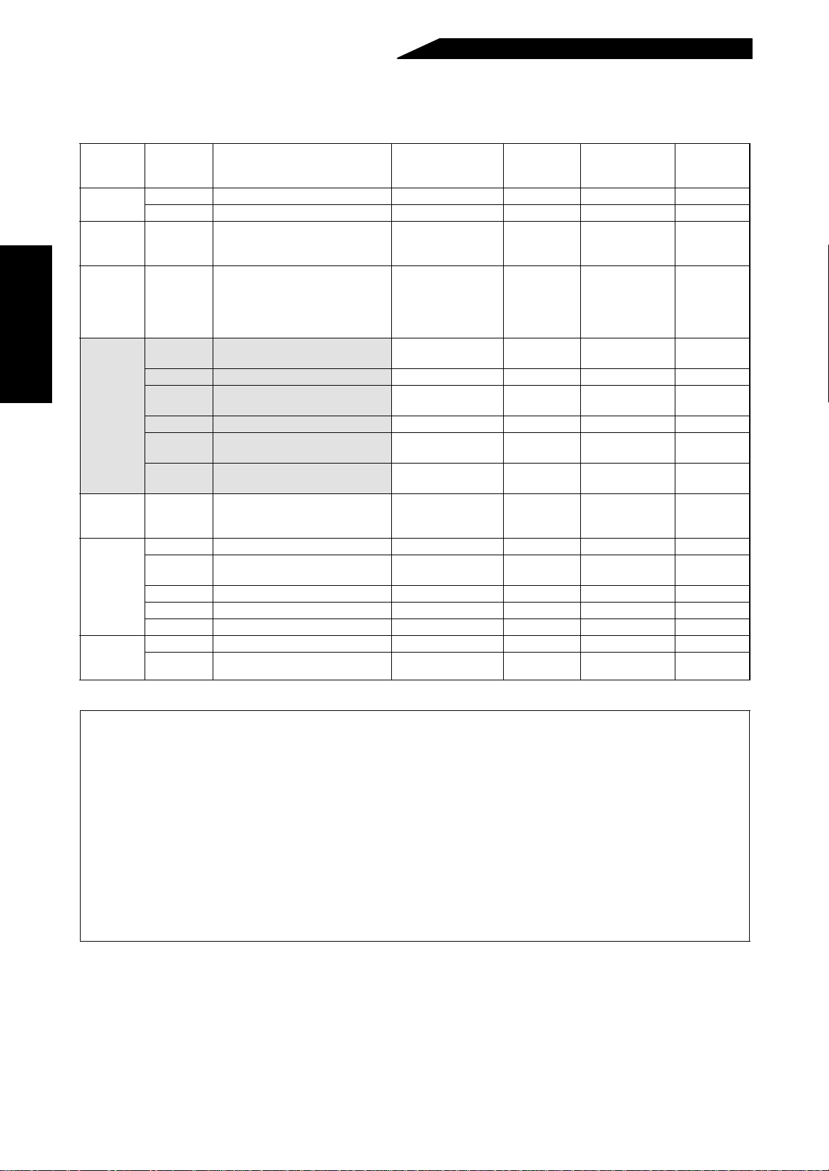
2.2 PARAMETER FUNCTION DETAILS
2.2.1 Parameter list
Function
–
Standard
operation
function
Multi-
function
output
terminal
function
Parameters
Display
functions
Automatic
restart
function
Operation
selection
functions
Calibra-
tion func-
tions
Parameter
No.
1 Power supply frequency 1 (Note1) ––60.00Hz –
2 Power supply frequency 2 (Note1) ––50.00Hz –
22 Overload signal detection level 0 to 200% 0.1 150.0%
40 Output terminal assignment 0 to 33 (Note 6) 1 1
51 Input power monitoring reference 0 to 100kW 0.1
52 PU main display data selection 0 to 3333 (Note 7) 1 123
53 Input voltage monitoring reference 0 to 500.0V 0.1
54 FM terminal function selection 0 to 3333 (Note 7) 1 123
55 Bus voltage monitoring reference 0 to 1000.0V 0.1
56 Current monitoring reference 0 to 500.00A 0.01
57 Restart selection 0, 9999 1 9999
65 Retry selection 0, 1, 2, 3 1 0
67
68 Retry waiting time 0.1 to 360.0 s 0.1 s 1.0 s
69 Retry count display erasure 0 – 0
77 Parameter write disable selection 1, 2 1 2
145 Parameter unit language switching 0, 1, 2, 3 1 0
900 FM terminal calibration –––
Number of retries at alarm
occurrence
Name Setting Range
0 to 10, 101 to 110 1 0
Minimum
setting
Increment
Factory Setting
Rated power
(Note 2)
220V/400V
(Note 3)
340V/680V
(Note 3)
Rated current
(Note 5)
Customer
Setting
Note: 1.You cannot set or c hange the values of Pr.1 “power supply frequency 1” and Pr. 2 “power supply
frequency 2”.
2.This set value varies with the capa city of the high power factor converter and is factory-set to the
rated power of the corresponding capacity.
3.These set values vary with the rated voltage of t he high power factor converter and is factory-set
according to the 200V/400V class.
4.The set values of the half-tone scree ned parameters can be changed if “1” ( write di sable) is set in
Pr. 77 “parameter write disable selection”.
5.This set value varies with the capa city of the high power factor converter and is factory-set to the
rated current of the corresponding capacity.
6.Use numerals 0 to 3 to set a two-digit value in Pr. 40 “output terminal assignment”.
7.Use numerals 0 to 3 to set a four-digit value in Pr. 52 “PU main display data selection” and Pr. 54
“FM terminal function selection”.
- 31 -
Page 42

2.2.2 Setting of parameters to improve the corresponding operational functions
Preset input frequency to the converter
To detect the overload signal
Pr.1 “power supp ly f re q uen cy 1 ”, Pr.2 “power supply frequency
2”
• Indicates that the converter is operable in the district where the
power supply frequency is 50Hz or 60Hz.
Parameter Number Factory Setting
1 60.00Hz
2 50.00Hz
Pr.22 “overload signal detection level”
• If the inr ush current of the hig h power factor converter exceeds the
set value of Pr. 22 “overload signal detection level”, the alarm
detection signal “OL” is displayed and output from the output
terminal “OL”. Set a value with reference to the rated current.
FR-PU02E
Overload signal detection signal
FW D EXT
To change the functions of the output
terminals Y1, Y2
Note: The set value (%) indicates the ratio of the inr ush current to
the rated current of the high power factor converter.
Pr.40 “output terminal assignment”
• Functions can be reassigned to output terminals Y1, Y2.
Set a 2-digi t inte ger in Pr. 40 “output ter minal ass ignment”. The value
of each digit indi cat e s th e fun c ti on of th e co rr espon d ing te rminal.
Pr.40= First digit Second digit
Y2 Y1
Pr.40 Setting Function Name Operation
When the input power supply is in
phase with the arithmetic result, the
0
(Factory setting)
1 Output voltage match
2
3
Power supply phase
detection signal
Instantaneous power
failure detection
Driving/regenerative
mode judgment
power supply phase detection signal is
locked. When they are out of phase,
the power supply phase detection
signal is unlocked and output from the
open collector output terminal.
When the bus voltage matches the
command value from the CPU, the
corresponding signal is output from the
open collector output terminal.
This signal indicates that an instantaneous power failure occurred.
Whether the mode is driving or
regenerative is judged. In the driving
mode, the open collector terminal does
not conduct.
- 32 -
Page 43

Note: 1.“Output” means that the open collector outputting built-in
transistor switches on (conducts).
2.When a one-dig it value is enter ed, the u nit re cogni zes that
“0” is in the first digit and te rmi nal Y2 ser ves to output the
power supply phase detection signal.
To set the reference values of terminal
FM
To set/change the display data on the
parameter unit (terminal FM)
Pr. 51 “input power monitoring reference”, Pr. 53 “input
voltage monitoring reference”, Pr. 55 “bus voltage monitoring
reference”, Pr. 56 “current monitoring reference”
• With these parameters, you can set the reference values of the
power, voltage, bus voltage and current input from the power
supply to the high power factor converter. Set values which are
suitable for the rated values of the power supply and high power
factor converter.
• These values are used as reference outputs to terminal FM.
• Parameters
Parameter
Number
51
53
55
56
Input power monitoring
reference
Input voltage monitoring
reference
Bus voltage monitoring
reference
Current monitoring
reference
Name Factory Setting
Rated power 0 to 100KW
220V/440V
(Note)
340V/680V
(Note)
Rated current 0 to 500.00A
Note: These set values vary with the voltage class of the high power factor
converter and are factory-set according to the 200V/400V class.
Setting
Range
0 to 500.0V
0 to 1000.0V
Pr. 52 “PU main display data selection”, Pr. 54 “FM terminal
function selection”
• The display data of the parameter unit can be set or changed.
Note that the moni tor display is not pr ovided by merely setting th e
parameter. Use the switches X1, X2 to change to the monitor
display.
• By setting or changing the value in Pr. 52 “PU main display data
selection”, current monitoring will vary.
(1) Each digit where the Pr. 52 (Pr. 54) value is set has relationships
with the positions of terminal X1, X2 switches.
FR-PU02E
52
0123
First
Second
Third
digit
Parameter: Pr.52 (Pr.54) =
Terminal (switch);
digit
Fourth
digit
digit
First digit Second digit Third digit Fourth digit
X1 OFF ON OFF ON
X2
ONONOFFOFF
- 33 -
Page 44

(2) The following values may be set in Pr. 52 (Pr. 54):
Pr. 52 (Pr. 54) Setting Displa y
0 Input current monitoring
1 B us voltage monitoring
2 Input voltage monitoring
3 I nput power monitoring
(3) Pr. 52 (Pr. 54) is factory-set as follows:
Parameter; Pr.52 (Pr.54) = 0(Note) 1 2 3
Since the terminals (switches) are factory-set to X1=OFF and
X2=OFF, the monitor scr een on the parameter uni t shows “input
current monitoring”.
Note:Basically, a four-digit value is entered in Pr. 52 (Pr. 54). “0”
set in the first of the four digits is not dis played. The factory
setting of “123” is recognized as “0123”.
<Factory setting of terminals (switches)>
(4) Shift operation for PU main monitoring
Three different monitors set in Pr. 52 “PU main display data” can
be called in sequence by pressing the [SHIFT] key.
- 34 -
Page 45

(5) Using the [MONITOR] key to select the monitor display
1) Press the [MONITOR] key, then the [HELP] key to call the
monitor list.
2) Make selection with the arrow keys.
3) Press the READ key to display the monitor.
Note that the monitors that may be read are limited.
<Monitor list>
1. Frequency
2. Current
3. Voltage
4. Alarm His
5. F Command
6. RPM
7. Shaft Trg
8. DC Link
9. Br Duty %
10. Therm OL
11. Peak I
12. DC Peak V
13. I/P Power
14. O/P Power
15. I/P Signal
16. O/P Signal
Input frequency [Hz]
Input current [A]
Input voltage [V]
Eight items of error definitions are displayed.
SORRY
No Function
on This Numb.
<CLEAR>
Converter output voltage [V]
SORRY
No Function
on This Numb.
<CLEAR>
Input power [kW]
SORRY
No Function
on This Numb.
<CLEAR>
Note: 1.Note that any value less than 5% of the high power factor
converter’s rated current cannot be detected or displayed.
2.By pressing th e [WRITE] key on any monitor display, the
first priority screen can be determined. This operation
allows the first prior ity screen to be disp layed immediately
after power-on or when the setting mode is switched to
the monitoring mode.
To select automatic restart after
instantaneous power failure
Pr.57 “restart selection”
• When automatic restart after instantaneous power failure has
been selected i n the inver ter paramet er “re start coasti ng time ”, set
“0” in Pr. 57 “restart sel e c ti on ”.
• When “9999” is set in Pr. 57, the converter (FR-HC) will stop the
inverter output due to the alarm signal “E.IPF” even if automatic
restar t after instantaneous p ower failure has been selected in th e
inverter parameter.
Pr.57 Setting Restart Operation
0Yes
9999 (factory setting) No
CAUTION
The motor will star t s uddenly (after re set time has elap sed)
when an instantaneous power failure has occurred.
When the restar t after instanta neous power failure function
is selected, stay away from the motor and machine.
Apply the supplied CAUTION labels to easily identifiable
positions when the restar t aft er instantane ous power failure
function is selected.
- 35 -
Page 46

To limit the error s reset f o r retry
E.OCT
Retry
Pr. 65 “retry selection”, Pr. 67 “number of retries at alarm
occurrence”, Pr. 68 “retry waiting time”, Pr. 69 “retry count
display erasure”
• When an error occurs in th e high power factor converter, the retry
function allows it to reset the alarm automatically and continue
operation.
(1) With Pr. 65 “retry selecti on”, you can limit the high power factor
converter errors reset for retry.
Pr.65 Alarms Reset for Retry
0No retry
1 Overcurrent shut-off (OCT)
2 Power supply fault (IPF) (Note 4)
3
Overcurrent shut-off (OCT),
power supply fault (IPF)
(2) With Pr. 67 “number of retries at alar m occurren ce”, you can set
the number of retries to be made when a high power factor
conve rter error occurs.
Pr.67 Setting Number of Retres Alarm Signal Output
0 (factory setting) Retry is not made. –
1 to 10 1 to 10 times Not output
101 to 110 1 to 10 times Output.
(3) With Pr. 68 “retry waiting time”, waitin g time from when a high
power factor converter error occurs until a restart is made can
be set in the range 0.1 to 360s.
(4) By reading the value of Pr. 69 “retry count display”, the
cumulative number of restart times su ccessf ully made by retr y is
provided. The set value of “0” erases thi s cumulative number of
times.
Note: 1.The high power factor converter automatically starts
operation after the tim e set in Pr. 68 “retry waiting time” has
elapsed. Exercise care not to jeopardize the operator.
2.The cumulative number in Pr. 69 “retry count display
erasure” is incremented by “1” when retry operation is
regarded as successful, i.e. when normal operation is
continued without any alarm occurring during a period four
times longer than the time set in Pr. 68 “retry waiting time”.
3.If alarms occur successively during a period four times
longer than th e above waiting time set in Pr. 68, the scr een
display of the parameter unit will be different from the
display provided when the first retry is made. (Option fault
“E.OPT”) Note that the error reset f or retry is not stored.
4.With 2 set in Pr. 65 “retr y selection” (power supply fault),
the IPF signal is detected when a power supply fault
occurs.
CAUTION
When you have selected the retry functi on, stay away from
the motor and machine. They will start suddenly (after a
given time has elapsed) when an ala rm occurs. When you
have selected the retry function, apply the supplied
CAUTION labels to easily identifiable positions.
- 36 -
Page 47

To set parameter write disable
Write
Inhibited
Pr.77 “parameter write disable selection”
• Prevents parameter values from being written from the parameter
unit.
Pr.77 Setting Write Disable Function
1 Parameter write disable
2 (factory setting) Parameter write enable
Note: 1.Mo nitor-related parameters Pr. 51, Pr. 53, Pr. 55 and Pr.
56 may be set at any time.
2.The Pr. 77 value may be written at any time.
CAUTION
If the setting is changed during operation, the high power
factor converter may stop operating due to al arm occurrence.
To change the language displayed on
the parameter unit
Pr.145 “
parameter unit language switching
”
• You can select the language displayed on the four-language
parameter unit FR-PU02ER
Set Value Language Displayed
0 English (factory setting)
1German
2 French
3 Spanish
Note: T his function is invalid for the FR-PU02
ARW
parameter (copy) unit is used.
-1
and copy unit FR-ARWER-1 (option).
-1
, FR-PU02E-1 or FR-
-1
- 37 -
Page 48
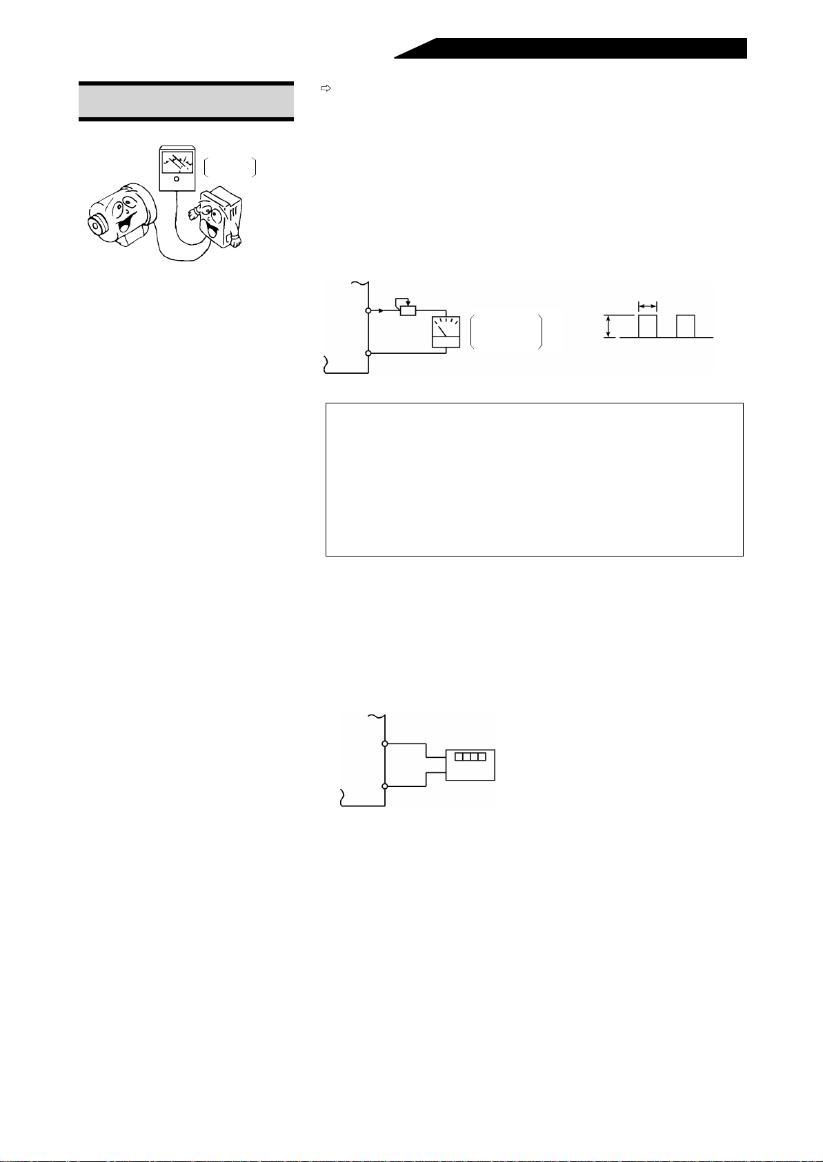
T o make the output calibration of
terminal FM
FM
Meter
DC ammeter
1mA full-scale
Pr.900 “FM terminal calibration”
• The meter connected to ter minal FM can be calibrated from the
parameter unit. This calibration function is common to all
monitored data selected in Pr. 54 “FM terminal function selection”.
• Terminal FM provides the pulse output as shown below. The
setting of Pr. 900 “FM terminal calibration” allows the meter
connected to the converter to be calibrated from the parameter
unit without providing a calibration resistor.
Calibration resistor (Note)
FM
1mA
SD
(+ )
( - )
Meter
1mA full scale
Analog meter
Pulse width T1: Adjusted with Pr. 900
T1
DC8V
Note: Calibration need not be made using Pr. 900 “FM term inal
calibration”. This r esistor is u sed when cali bration must be
made near the frequency meter for such a reason as a
remote frequency meter. Note that the needle of the
frequency meter may not deflect to full-scale when the
calibration resistor is co nnected. In this case, use both the
resistor and Pr. 900 “FM terminal calibration” to make
calibration.
• Monitoring using a digital meter
A digital value can be displayed on a digital counter using the
pulse train signal from the FM terminal. By making monitoring
selection, the ratios of the FM terminal mon ito r ing ca n be set in Pr.
51 “input power monitoring reference”, Pr. 53 “input voltage
monitoring reference”, Pr. 55 “bus voltage monitoring reference”
and Pr. 56 “current monitoring reference”.
FM
SD
1440 pulses/s
+
- 38 -
Digital indicator
Digital meter
Example: Koyo Electronic Industry's TC-41
Page 49
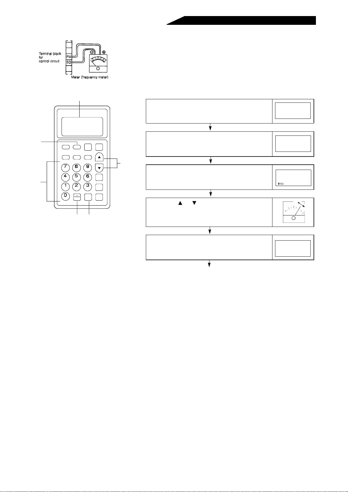
FR-PU02E
Display
PARAMETER UNIT
-1
• Calibration procedure
(1) Connect a meter across c onverter te rminals FM and SD. (Note
the polarity. FM is the positive terminal.)
(2) When a calibration resis tor has already been connected , adjust
the resistance value to zero or remove the resistor.
(3) Set the required value in Pr. 54 “FM terminal functio n selection”.
Preset the parameter value as required by the output signal.
1) Press the [SET] key. . . . . . The parameter setting
mode is entered.
SETTING MODE
Set Pr. NO.
FOR PR. List
<HELP>
1)
MONITOR
HELP
ACCEL DECEL THM
2)
HIGH MID LOW
BOOST
SET
SHIFT
READ
EXT
O P
CLEAR
V/FMINMAX
WRITE STOP
P U
O P
4)
FWD
REV
the [READ] key.
3) Input current is displayed.
4) Using the [ ] or [ ] key,
adjust the meter indicator
2) Type [9][0][0] and press
2) 5)
to a predetermined
position
5) Press the [ WRITE] key. . . . . . Calibration is complete.
. . . . . The data as shown on
the right is displayed.
. . . . . The meter indica tor
moves. (It takes a long
time until the indicator
moves.)
900 FM Tune
Run Inverter
set 60.00Hz
PU
901 AM Tune
Mntrl 2.31A
<WRITE>PU
900 FM Tune
Completed
<MONITOR>
Press the [MO N ITOR] or [SET] key to
switch to the corresponding mode.
- 39 -
Page 50
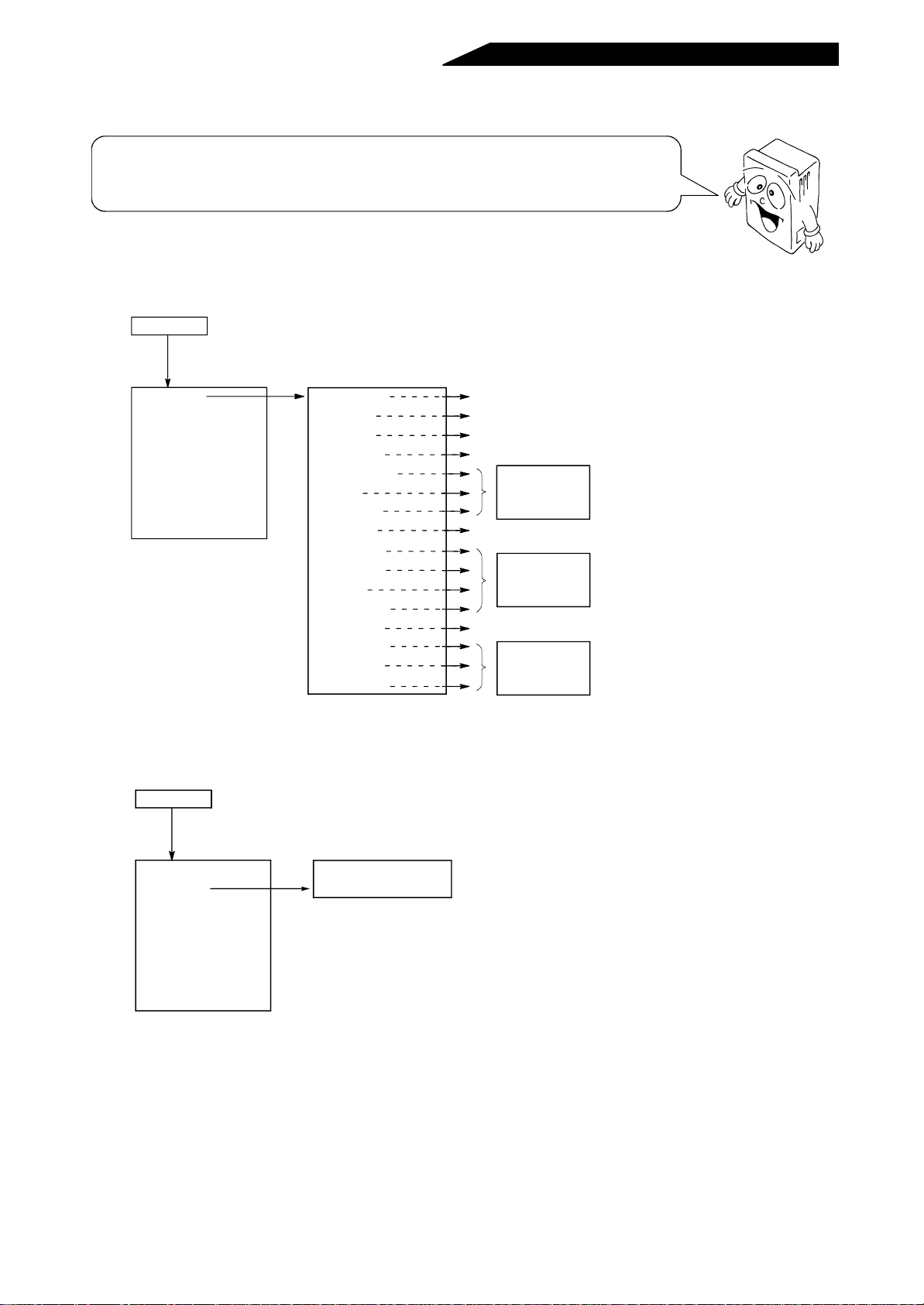
2.3 HELP FUNCTIONS
Use the HELP key to select monitoring, set parameter values, or clear parameters. On
any monitor sc reen, press the H ELP key twice to ca ll the help menu, w ith which variou s
functions can be set or selected. Note that there are restrictions.
2.3.1 Definitions of the help function displays (1) Monitoring function
HELP key
Twice
1. MONITOR
2. PU Oper
3. Pr. List
4. Pr. Clear
5. Alarm Hist
6. Alarm Clear
7. Inv. Reset
8. T/Shooting
(2) PU operation function
HELP key
Read Read
1. Frequency
2. Current
3. Voltage
4. Alarm His
5. F Command
6. RPM
7. Shaft Trg
8. DC Link
9. Br Duty %
10. Therm OL
11. Peak I
12. DC Peak V
13. I/P Power
14. O/P Power
15. I/P Signal
16. O/P Signal
* This function cannot be used. Press the CLEAR key to return to the help selection
screen.
Input frequency [Hz]
Input current [A]
Input voltage [V]
Alarm history display
SORRY
No Function
on This Numb.
<CLEAR>
Converter output voltage [V]
SORRY
No Function
on This Numb.
<CLEAR>
Input power [kW]
SORRY
No Function
on This Numb.
<CLEAR>
*
*
*
1. MONITOR
2. PU Oper
3. Pr. List
4. Pr. Clear
5. Alarm Hist
6. Alarm Clear
7. Inv. Reset
8. T/Shooting
Read
1. PU; Diectly IN
2. JOG; Jogging
* This function cannot be used. Press the CLEAR key to return to the help
selection screen.
*
- 40 -
Page 51
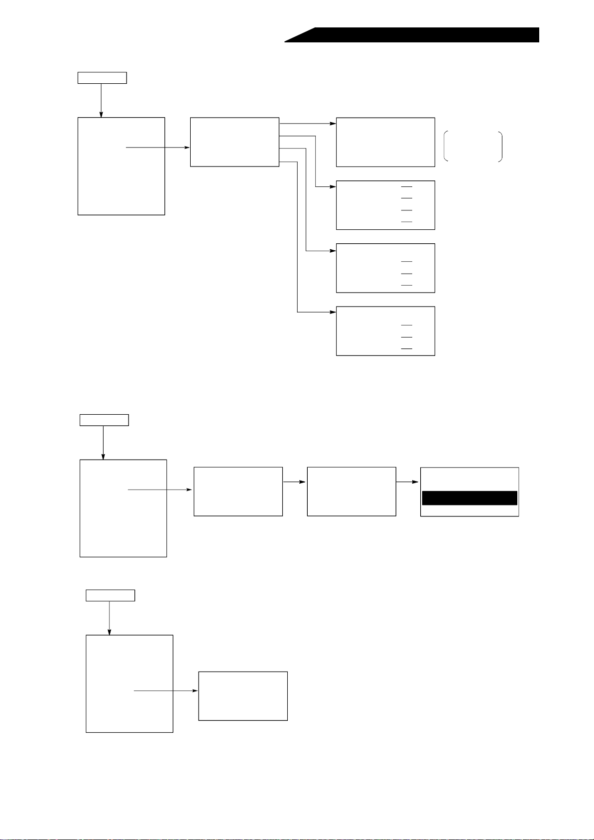
(3) Parameter setting function (Note that only “1 Setting” is valid)
HELP key
1. MONITOR
2. PU Oper
3. Pr. List
4. Pr. Clear
5. Alarm Hist
6. Alarm Clear
7. Inv. Reset
8. T/Shooting
Read
1. Setting MODE
Read
2. Pr. List
3. Set Pr. List
4. Def. Pr. List
* This function cannot be used. Press the CLEAR key to return to the help
selection screen.
SETTING MODE
Set Pr. NO
For Pr. List
<HELP>
1
2
3
4
Set Pr. Lists
Pr.0
Pr.1
Pr.2
DEF Pr. List
Pr.0
Pr.1
Pr.2
Following the
instruction on
the screen.
*
*
*
(4) Parameter initialization function... Returns parameter values to the factory setting.
HELP key
1. MONITOR
2. PU Oper
3. Pr. List
4. Pr. Clear
5. Alarm Hist
6. Alarm Clear
7. Inv. Reset
8. T/Shooting
Read
1. Clear Pr.
2. Clear All
3. Clear None
(5) Alarm history display function
HELP key
1. MONITOR
2. PU Oper
3. Pr. List
4. Pr. Clear
5. Alarm Hist
6. Alarm Clear
7. Inv. Reset
8. T/Shooting
Read
1 5
2 6
3 7
4 8
Clear Pr.
Exec <WRITE>
Cancel <CLEAR>
Write
Clear Pr.
Executing
- 41 -
Page 52
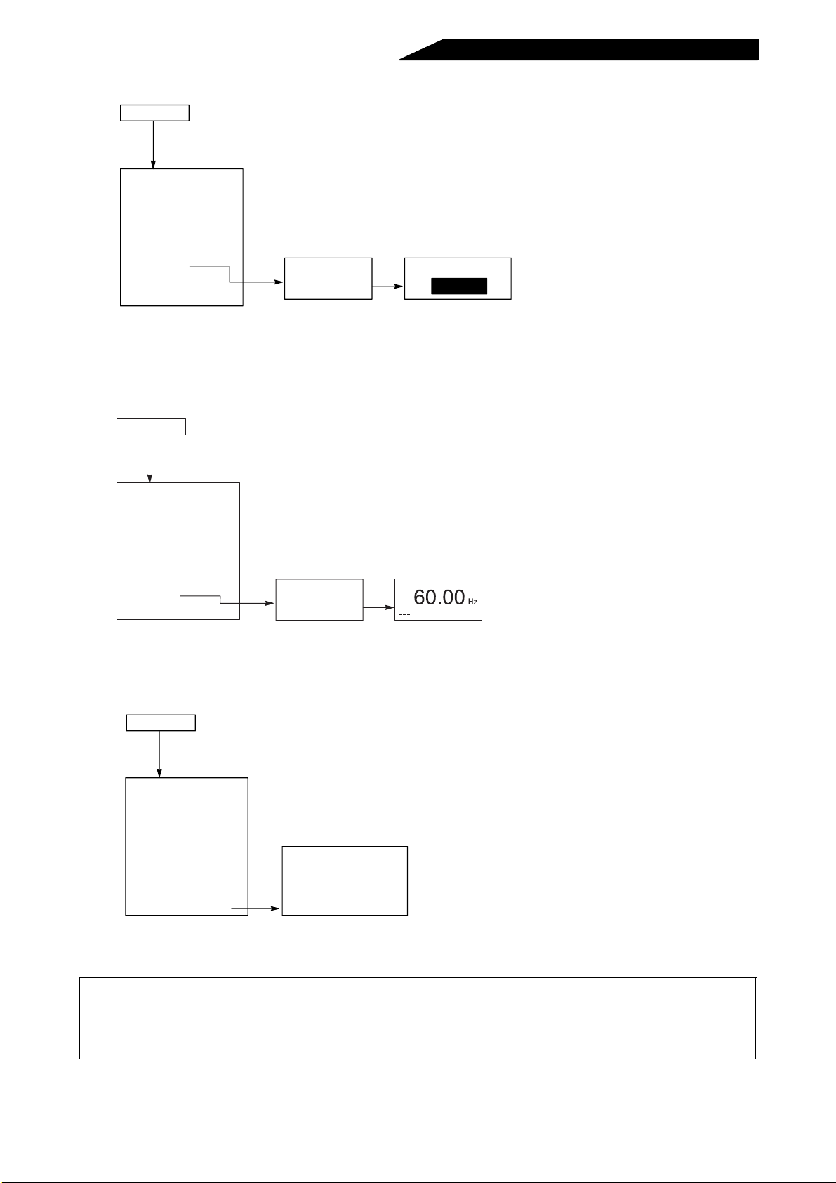
(6) Alarm history clear function (Erases alarm history)
to
return to the help selection screen.
HELP key
1. MONITOR
1. MONITOR
2. PU Oper
3. Pr. List
4. Pr. Clear
5. Alarm Hist
6. Alarm Clear
7. Inv. Reset
8. T/Shooting
Read
ALARM CLEAR
Exec<WRITE>
Cancel<CLEAR>
Write
ALARM CLEAR
Completed
(7) Converter reset (Resets the high power factor converter)
Note: Though the disp lay shows inve rter reset, note that th e inverter is not res et. (To reset the inverter
together with the converter, terminals RSO-RES and terminals SE-SD must have been
connected.)
HELP key
1. MONITOR
1. MONITOR
2. PU Oper
3. Pr. List
4. Pr. Clear
5. Alarm Hist
6. Alarm Clear
7. Inv. Reset
8. T/Shooting
Read
INV. RESET
Exec<WRITE>
Cancel<CLEAR>
Write
FWD EXT
Note:
Returns to the screen at
the power on (first priority
screen (refer to page 35))
(8) Troubleshooting (Note that this function is invalid)
HELP key
1. MONITOR
2. PU Oper
3. Pr. List
4. Pr. Clear
5. Alarm Hist
6. Alarm Clear
7. Inv. Reset
8. T/Shooting
* This function cannot be used. Press the HELP key to return to the previous screen or press the MONITOR or SET key
Read
1 M. Not Run
2 M. Spd Error
3 M. A/Dec Err
4 M. Curr. High
*
Note: 1.There are restrictions on the help functions of the high power factor conv erter compared to those
of the inverter.
2.When you have selected an invalid item, press the CLEAR key to return to the help selection
screen.
- 42 -
Page 53

2.4 CONVERTER RESET
The high power factor converter can be reset by any of the following three operations.
Note that resetting clears (erases) the cumulative internal heat value of the electronic
overcurrent protector and the number of retries.
Operation 1
Using the help function, reset the inverter.
For details, see “7 CONVERTER RESET”
on page 42.
Operation 2
Switch the power off once. After more than
0.1s, switch it on again.
Note: When the Pr. 57 (Coasting time for
Operation 3
Connect the reset terminal RES-SD for more
than 0.1s, then disconnect.
Note: Avoid resetting the converter as part of its operation cycle.
automatic restart after instantaneous
power failure/commercial power supplyinverter switch-over) setting is other
than “9999”, this operation is mistaken
for an automatic restart after
instantaneous power failure and the
inverter cannot be reset. Hence, the
power should be switched on again
about 5s after the control power has
been lost.
- 43 -
Page 54

3. PROTECTIVE FUNCTIONS
This chapter offers details on the “protective functions” of
this product.
Always read the precautions, etc. before starting use.
3
3.1 ERRORS.................................................................................................... 44
3.2 MAINTENANCE AND INSPECTION ......................................................... 46
Page 55
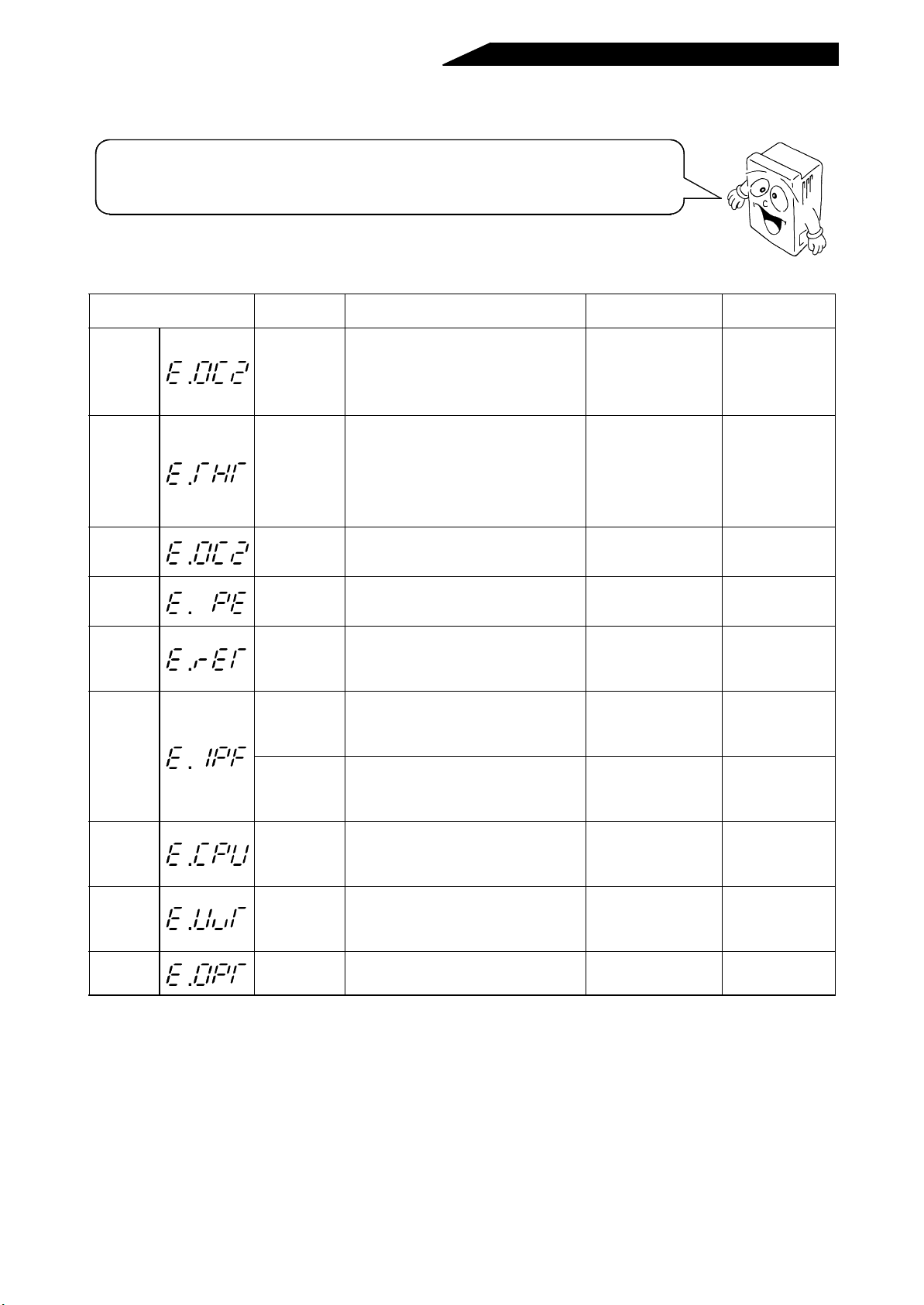
3.1 E RRORS
If any fault has occurred with the high power factor converter, the corresponding protective
function is activated to bring the high power factor converter to an alarm stop and
automatically give the corresponding error (alarm) indication on the parameter unit display.
When the protective function is activated, refer to page 42 on how to reset the converter.
3.1.1 Error (alarm) definitions and remedies
Parameter Unit Display
(Note 4)
Stedy
Spd Oc
Inv.
Overload
Stedy
Spd Oc
Corrupt
Memory
Retry No.
Over
Inst. Pwr.
Loss
CPU Fault CPU error
Under
Voltage
Option
Fault
Definition Cause Check Point Remedy
Overcurrent
protection
Electronic
overload
protection
Main circuit
device heat
Parameter
error
Retry count
excess
Instantaneous
power failure
protection
Power supply
fault
Undervoltage
protection
Option fault Displayed during error retry.
If the input current exceeds a given level
during operation of the high power factor
converter, the operations of the high
power factor converter and inverter are
stopped.
To protect the IPM, the electronic
overload protection is activated in
response to the high power factor
converter input according to the inversetime characteristics to stop the operations
of the high power factor converter and
inverter.
If the main circuit devices are heated due
to cooling fan stop, overload, etc., the
high power factor converter is stopped.
If any stored parameter error occurs, the
operations of the high power factor
converter and inverter are stopped.
If proper operation cannot be resumed
within the given number of retries, the
outputs of the high power factor converter
and inverter are stopped.
If power is restored within about 100ms
after a power failure of longer than 15ms,
the operations of the high power factor
converter and inverter are stopped.
If cable disconnection or other power
supply fault has occurred, the outputs of
the high power factor converter and
inverter are stopped.
If the CPU arithmetic does not end within
a given period, the operations of the high
power factor converter and inverter are
stopped.
If the DC bus voltage falls below 150VAC
(300VAC for 400V class), the operations
of the high power factor converter and
inverter are stopped.
Check for sudden load
variation.
Check for overload on
motor.
Check for low carrier
frequency on inverter
side. (Note 3)
Check for overload.
Check if parameters
are written too many
times.
Find the fault cause.
Find the instantaneous
power failure cause.
Check for power cable
disconnection.
Check for a start of
large-capacity motor.
Eliminate sudden
variation.
Change the fan,
remove a fan
obstacle. (Note 1)
Reduce load
weight. Increase
the high power
factor converter
capacity.
Reduce load
weight.
Change the fan.
Change the high
power factor
converter.
Check power
supply system
equipment, e.g.
power capacity.
Note: 1.This alarm does not oc cur if the coo ling fan stops, but it will occur to prevent the main circuit devices
from overheating due to the cooling fan stopping.
2.If the alar m is still displayed on the parameter unit after reme dy, t he internal circuit may be faulty.
Consult your sales representative.
3.For the E.THT error, the electronic overcurrent protection of th e inverter should ac tivate earlier than
that of the high power factor converter. However, the inverter’s electronic overcurrent protection
“E.THT” has the proper ty that it is activated earlie r at a higher carrier freq uency and later at a lower
carrier frequency. Therefore, when the carrier frequency of the inverter is low, the electronic
overcurrent protection of the high power factor converter may be activated earlier.
4.Displayed on the FR-PU02E
-1
(option) and is not displayed on the FR-PU03E (option).
- 44 -
Page 56

3.1.2 Faults and check points
Fault Check Point
Checking the connections
• Check that wiring is correct.
Unit does not operate properly.
POWER lamp is not lit.
Charge lamp is not lit.
Reactors become unusually hot.
Inverter is inoperative.
Reactors generate unusual noise. Check that phase sequence is correct.
• Check that proper power supply voltage is applied.
• Check that phase sequence is correct.
When phase sequence is correct, check that terminals
SOF-SD or terminals RES-SD are connected.
Checking the connections
• Check that connections are correct.
• Check that control circuit terminals R, S, T are wired correctly.
• Check f or damaged resistor in the external box.
Checking the connections
• Check that connections are correct.
• Check that main circuit terminals R4, S4, T4 are wired correctly.
Checking the connections
• Check that the reactors 1 and 2 are connected in correct sequence.
Checking the settings
• Check that the parameter setting of the inverter is correct. (Since the
parameter setting method varies with the inverter series, refer to the inverter
instruction manual.)
- 45 -
Page 57

3.2 MAINTENANCE AND INSPECTION
The high power factor converter is a static unit consis ting mainly of semiconductor
devices. Daily inspection must be performed to pr event any fault from occurring due
to adverse influence by the installati on environment, such as temperature, humidi ty,
dust, dirt and vibration, changes in the parts with time, service life, and other
factors.
3.2.1 Precautions for maintenance and inspection
For some shor t time af ter the power is switched off, the smoothi ng capac itor remai ns at a high voltage. Before
accessing the high power factor converter for inspection, make sure that the charge lamp is off and check that
the voltage across th e main circui t termin als P-N of the hig h power factor converter is 30VDC or less using a
tester, etc. (F o r th e lo ca ti on of the cha rg e la mp, see the terminal block ar r a ng em en t on pa g e 60 .)
CAUTION
The reactors 1 and 2 are hot. Take care not to get burnt.
3.2.2 Check items (1) Daily inspection
• Check the following during operation:
(1) Improper installation environment
(2) Cooling system fault
(3) Unusual vibration and noise
(4) Unusual overheat and discoloration
• During operation, check the input voltage of the high power factor converter using a tester.
(2) Periodic maintenance and inspection
• Check the areas inaccessible during operation and requiring period inspection.
(1) Cooling system: Clean the air filter, etc.
(2) Screws and bolts: Check that they are securely tightened and retighten as necessary.
(3) Conductors and insulating materials: Check for corrosion and damage.
(4) Insulation resistance: Measure.
(5) Cooling fan, smoothing capacitor, relay: Check and change if necessary.
Note:Have a proper understand ing of the definition s of power and error ( alar m) indic ations pr ovided for the
high power factor converter. Also, have a p roper un derstand ing of th e setti ngs with th e pa rameter unit
and record proper set values. (Enter the values into the Customer Setting s ection of the “Parameter
List” on page 31.)
See the next page for the Inspection List.
(3) Insulation resistance test using megger
(1) Before performing the insulation resistance test using a megger on the external circu it, disconnect
the cables from all terminals of t he hig h p ower factor convert er s o t hat the tes t voltage is not app li ed
to the high power factor converter.
(2) For the continuity test of the control circuit, use a tester
(high resistance range) and do not use the megger or
Power supply
High power
R4
factor converter
S4
T4
P
N
Inverter
INV
buzzer.
(3) For the high power factor converter, conduct the
insulation resistance test on the main circuit only
as shown on the right and do not perform the test
500VDC
megger
Earth terminal
on the control circuit. (Use a 500VDC megger.)
- 46 -
Page 58

Daily and Periodic Inspection
Area of
Inspec-
tion
General
Main
circuit
Cooling
system
Display
Inspection
Item
Surrounding
environment
Overall unit
Power
supply
voltage
General
Conductors,
cables
Ter mina l
block
Converter
module
Smoothing
capacitor
Relay
Resistor
Cooling fan
Display
Meter
Interval
Description
Check ambient tempe ratur e,
humidity, dust, dirt, etc.
Check for unusual vibration
and noise.
Check that main circuit
voltage is normal.
(1) Check with megger
(across main circuit
terminals and ground
terminal).
(2) Check for loose screws
and bolts.
(3) Check for overheat on
each part.
(4) Clean.
(1) Check conductors for
distortion.
(2) Check cable sheaths
for breakage.
(3) Check for discoloration.
Check for damage. ! Visual check No fault
Check resistance across
terminals.
(1) Check for liquid leakage.
(2) Check for safety valve
projection and bulge.
(3) Measure electrostatic
capacity.
(1) Check for chatter during
operation.
(2) Check for rough surface
on contacts.
(1) Check for crack in
resistor insulation.
(2) Check for open cable.
(1) Check for unusual
vibration and noise.
(2) Check for loose
connection.
(1) Check for power lamp
blown.
(2) Clean.
Check that reading is
normal.
Periodic
Daily
1
year2years
!
!
!
! (1) Disconnect all cables
!
!
!
!
! (1), (2) Visual check. (1), (2) No fault.
!
!
!
!
!
!
!
!
!
!
!
!
!
Method Criterion Instrument
See note on page 13.
Visual and auditory
checks.
Measure voltage across
high power factor
converter terminals R, S,
T-P 4, S 4, T4.
from high power factor
converter and measure
across terminals R4,
S4, T4, P, N and
ground terminal with
megger.
(2) Retighten.
(3) Visual check.
Disconnect cables from
converter and measure
across terminals R4, S4,
T4 P, N with tester ×1
range.
(1), (2) Visual check.
(3) Measure with capac-
ity meter.
(1) Auditory check.
(2) Visual check.
(1) Visual check. Cement
resistor, wirewound
resistor.
(2) Disconnect one end
and measure with
tester.
(1) Turn by hand with
power off.
(2) Retighten.
(1) Lamps indica te
indicator lamps on
panel.
(2) Clean with rag.
Check reading of meters
on panel.
Ambient temperature:
-10°C to +50°C, nonfreezing.
Ambient humidity: 90%
or less, non-condensing.
No fault.
170 to 242V
(323 to 506V) 50Hz
170 to 253V
(323 to 506V) 60Hz
(1) 5M or more.
(2), (3) No fault.
(See the next page.) Analog tester
Ω
(1), (2)
(3)85% or more of
rated capacity.
(1) No fault.
(2) No fault.
(1) No fault.
(2) Error should be
within ±10%
of indicated
resistance value.
(1) Smooth rotation.
(2) No fault.
(1) Check that lamps
are lit.
Must satisfy specified
and management
Ω
No fault.
values.
Thermometer,
hygrometer,
recorder
Tester, digital
multimeter
500VDC class
megger
Capacity
meter
Tester, digital
multimeter
Voltmeter,
ammeter, etc.
Customer
setting
Note:Values f or the 400V class are indicated in parentheses.
- 47 -
Page 59
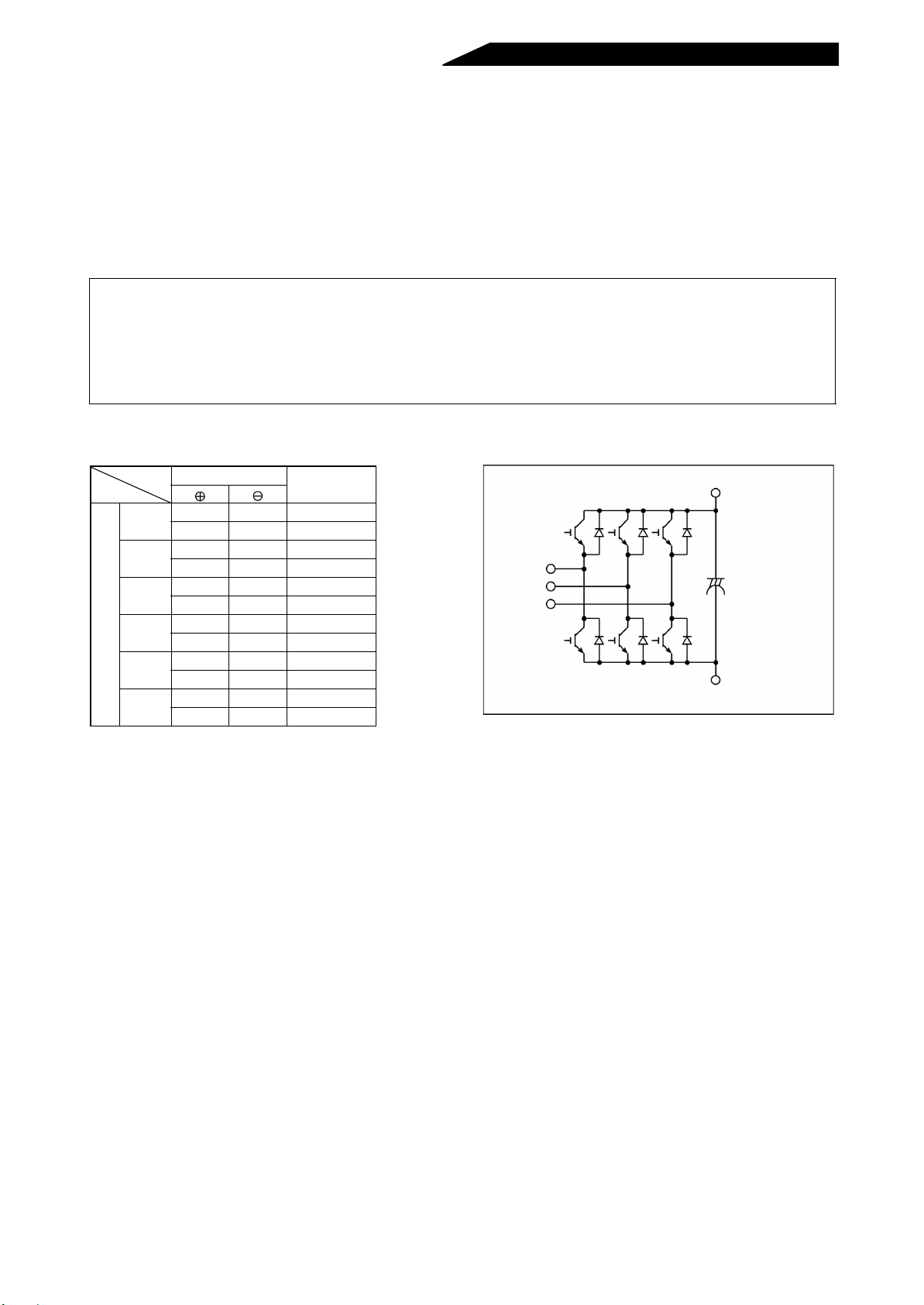
• Checking the converter module
<Preparation>
(1) Disconnect the external power supply cables (R4, S4, T4, N, P).
(2) Prepare a tester. (Use 1 range.)
Ω
<Checking method>
Change the polarity of the tester alternately at the main circuit terminals R4, S4, T4, P and N of the converter,
and check for continuity.
Note: 1.Before measurement, check that the smoothing capacitor is discharged.
2.At the time of discontinuity, the measured value indicated is a nearly infinite value. Due to the
influence of the smoothing capacitor, continuity may be instantaneously established a nd i nfi nite not
indicated. At the ti me of continuity, t he measured value is several to several ten ohms dependi ng
on the module type, tester type, etc. If all meas ured values are almost t he same, the modu les are
without fault.
<Module device numbers and te rminals to be checked>
Converter module
D1
D2
D3
D4
D5
D6
Tester Polarity
R4 P Discontinuity
P R4 Continuity
S4 P Discontinuity
P S4 Continuity
T4 P Discontinuity
P T4 Continuity
R4 N Continuity
N R4 Discontinuity
S4 N Continuity
N S4 Discontinuity
T4 N Continuity
N T4 Discontinuity
Measured
Value
(Assumes the use of an analog meter.)
R4
S4
T4
D1 D2 D3
D5
D4
P
C
D6
N
- 48 -
Page 60

3.2.3 Replacement of parts
The high power factor converter consists of many electronic parts such as semiconductor devices.
The following parts may deteriorate with age because of their structures or physical charact eristics, leading
to reduced perfor mance or failure of the high power factor converter. For preventive maintenance, the par ts
must be changed periodically.
See the following table for the high power factor conver ter par ts r eplacement gui de. Lamps and other shor tlife parts must also be changed during periodic inspection.
Replacement Parts of the High Power Factor Converter
Part Name
Cooling fan 2 to 3 years Change (as required)
Smoothing capacitor in
main circuit
Smoothing capacitor on
control board
Relays – Change as required.
Standard Replacement
Interval
5 years Change (as required)
5 years Change the board (as required).
Description
Note:For part replacement, contact the nearest Mitsubishi FA center.
(1) Cooling fan
The cooling fan cools heat-generating parts su ch as the main circuit semi conductor devices. The life of
the cooling fan bearing is usually 10, 000 to 35,000 hours. Hence, the cooling fan must be changed every
2 to 3 years if the high power factor converter is run continuously. When unusual noise and/or vibration is
noticed during inspection, the coo li ng fan must be changed immediately.
(2) Smoothing capacitors
A large-capacity al uminum el ectroly tic capa citor is used for smoothi ng the DC in the main circui t, and an
aluminum electrolyti c capacitor is also u sed for stabilizing the contr ol power in the control ci rcuit. Their
characteristics are adversely affected by ripple current, etc. When the high power factor converter is
operated in ordinary, air-conditioned environment, change the capacitors about every 5 years.
When 5 years have elapsed, the capacitors will deteriorate more rapidly. Check the capacitors at leas t
every year (less than six months if the life will be expired soon).
Check the following:
1) Case (side faces and bottom face for ex pansion)
2) Sealing plate (for remarkable warp and extreme crack)
3) Explosion-proof valve (for excessive val ve expansion and operation)
4) Appearance, external crack, discoloration, leakage.
When the measured capacitance of the capacitor has reduced below 85% of the rating, change the
capacitor. For capacitance measurement, it is recommended to use a handy device available on the
market.
(3) Relays
To prevent a contact fault, etc., relays must be changed according to the number of accumulative
switching times (switching life).
- 49 -
Page 61

3.2.4 Measurement of main circuit voltages, currents and powers
r
• Measurement of voltages and currents
When instruments for commercial frequency are used for measurement, measure the following circuits
using the following instruments.
• When installing instruments, etc. on the high power factor converter output side
When the wiring distance is long between the high power factor converter and inverter, the instruments
may generate heat due to line leakage currents in especially 400V class. Select the devices which have
large enough current rating.
• There is an output voltage across te rmi nals P-N of th e high power factor converter and thi s voltage can be
measured by a moving-coil instrument (tester). This voltage varies with the power supply voltage and
reduces when load is applied.
Power supply
W
W
W
External box
Reactor 1
A
11
V
U
12
V
V
13
V
W
U
A
V
A
W
Reactor 2
Converter
R4
S4
T4
P
N
+
To inverte
V
-
<Typical Measuring Points and Instruments>
External box Converter
Reactor 1
Power supply
Power meter
Recommended: YOKOGAWA251
Digital power meter
(Can measure voltage, current,
power and power factor)
Reactor 2
R4
S4
T4
P
N
+
V
To inverter
-
<Typical Measuring Points and Instruments>
• Classification and Application of Indicating Electric Instruments by Operation Principle
Type Symbol Principle Indication
Uses force working between the
Moving-coil type
magnetic field of a permanent
magnet and a current flowing in
the moving coil.
Uses force working between the
Moving-iron type
magnetic field of a current flowing
in the fixed coil and the moving
iron.
Electrodynamic
type
Air
core
Uses force working between
currents flowing in two coils.
DC
(Mean value)
AC
(Effective value)
AC/DC
(Effective value)
Applied
Instrument
Voltmeter,
ammeter,
resistance
meter,
thermometer,
flux meter,
speed meter
Voltmeter,
ammeter
Wattmeter,
voltmeter,
ammeter
High in sensitivity and most often
used. Power consumption small,
rarely affected by external
magnetic field.
Rigid in structure and low in price.
Greatly affected by external
magnetic field, frequency and
waveform.
Wattmeter is graduated equally.
Affected by external magnetic field
and consumes large power. May
be used as a standard AC/DC
instrument.
Features
- 50 -
Page 62

Measuring Points and Instruments
Item Measuring Point Measuring Instrument
Power supply voltage
V1
Power supply side current
I1
Power supply side power
P1
Power supply side power f act or
Pf1
Converter output Across P-N
Meter signal Across FM(+)-SD
Alarm signal
(Reference Measured Value)*
Remarks
Across R-S, S-T and T-R
R, S and T line currents
At R, S and T, and across R-
S, S-T and T-R
Moving-iron type AC
voltmeter
Moving-iron type AC
ammeter
Electrodynamic type
single-phase wattmeter
Commercial power supply
170 to 242V (342 to 506V) 50Hz
170 to 253V (342 to 506V) 60Hz
=W11+W12+W13
1
P
(3-wattmeter method)
Calculate after measuring power supply voltage, power supply side current and power supply side
power.
P
Pf
1
= × 100%
1
-----------------
×
3V1I
¥
1
Inverter LED display is lit.
Moving-coil type
(such as tester)
1.35 × V1
Max. 380V (760V) during
regenerative operation
Approx. 5VDC at max. frequency
(without meter)
Moving-coil type
(T ester, etc. may be used)
(Internal resistance:
50kΩ or larger)
Pulse width T1: Adjusted
with Pr. 900
Approx. 10VDC at maximum
frequency
(without frequency meter)
20 to 30VDC when open.
ON voltage: 1V or less
Continuity check
<Normal> <Fault>
Across A-C
Across B-C
Moving-coil type
(such as tester)
Across A-C:
Discontinuity Continuity
Across B-C:
Continuity Discontinuity
SD is common.
Note 1: Do not use a tester because accurate data will not be obtained.
* Values in parentheses indicate those for 400V class.
- 51 -
Page 63

4. PRECAUTIONS FOR SELECTION
This chapter provides details on “precautions for selection”
in using this product.
Always read the precautions, etc. before starting use.
4
4.1 PRECAUTIONS FOR SELECTING PERIPHERAL DEVICES .................. 52
Page 64

4.1 PRECAUTIONS FOR SELECTING PERIPHERAL DEVICES
4.1.1 Measures against noises
In this section, noises indicate those of more than 40th to 50th high frequencies in a power distribution
system, which assume generally irregular conditions.
Some noises enter the high power factor converter to adversely affect it and others ar e radiated by the high
power factor converter to adversely affect peripheral devices. Though the high power factor converter is
designed to be im mune to noise s, it handles low-level signals, so it re quires the following bas ic measures to
be taken. Also, since the high p ower factor converter chops ou tput voltage at hi gh carr ier frequency, it could
generate noises. If these noise s affect peripheral devices, measures should be taken to suppress noises.
The measures differ slightly depending on noise propagation paths.
1) Basic measures
• Do not run the power cables (I/O cables) and signal cables of the high power factor converter in parallel with each
other and do not bundle them.
• Use twisted shield cables for the detector connecting and control signal cables and connect the screen of the shield
cables to terminal SD.
• Ground the reactors 1, 2, external box, high power factor converter, inverter, motor, etc. at one point.
2) Measures against noises which enter and affect the high power factor converter
When devices which generate many noises (which use magnetic contactors, magnetic brakes, many relays, for
example) are installed near the high power factor converter and the high power factor converter may be affected by
noises, the following measures must be taken:
• Provide surge suppressors for devices that generate many noises to suppress noises.
• Fit data line filters to signal cables.
• Ground the shields of the detector connection and control signal cables with a metal cable clamp.
3) Measures against noises which are radiated by the high power factor converter to affect peripheral
devices
Noises generated by the high power factor converter are largely classified into those radiated by the cables connected
to the high power factor converter and high power factor converter’s main circuit (I/O), those electromagnetically and
electrostatically inducted to the signal cables of the peripheral devices close to the main circuit power supply, and
those transmitted through the power supply cables.
Converter-generated
noises
Air-propagated noises
Magnetic induction
noises
Static induction noises
Cable-propagated
noises
.. Path 4, 5
.. Path 6
Noises directly
radiated by converter
Noises radiated
by power cables
Noises propagated
through power cables
Sneak noises from
ground cable due to
leakage current
.. Path 1
.. Path 2
.. Path 7
.. Path 8
- 52 -
Page 65
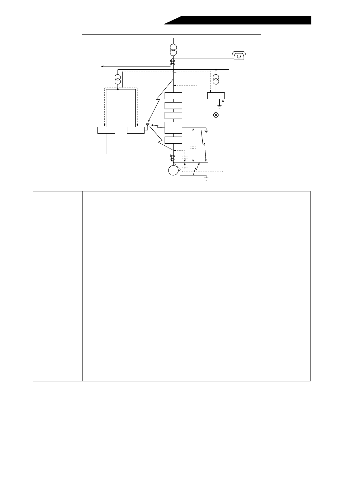
5
Telephone
Reactor 1
Extern al box
Reactor 2
High power
factor
converter
Inverter
IM
7
6
4
3
Instrument
7
2
1
Receiver
3
Motor
Noise Path Measures
When devices which handle low-level signals and are susceptible to noises (such as instruments, receivers
and sensors) are installed near the high power factor converter and their signal cables are contained in the
same panel as the high power factor converter or are ru n near the high power factor converter, the devices
may be affected by air-propagated noises and the following measures must be taken:
(1) Install easily affected devices as far away from the high power factor converter and inverter as possible.
1, 2, 3
(2) Run easily affected signal cables as far away from the high power factor converter and inverter as
possible.
(3) Do not run the signal cables and power cables (high power factor converter I/O cables) in parallel with
each other and do not bundle them.
(4) Insert line noise filters into I/O and radio noise filters into cables input to suppress cable-radiated noises.
(5) Use shield cables for signal cables and power cables and run them in individual metal conduits to
produce further effects.
When the signal cables are run in parallel with or bundled with the power cables, magnetic and static
induction noises may be propagated to the signal cables to affect the devices and the following measures
must be taken:
(1) Install easily affected devices as far away from the high power factor converter and inverter as possible.
4, 5, 6
(2) Run easily affected signal cables as far away from the high power factor converter and inverter as
possible.
(3) Do not run the signal cables and power cables (high power factor converter and inverter I/O cables) in
parallel with each other and do not bundle them.
(4) Use shield cables for signal cables and power cables and run them in individual metal conduits to
produce further effects.
When the power supplies of the peripheral devices are connected to the power supply of the high power factor
converter in the same line, high power factor converter-generated noises may flow back through the power
7
supply cables to the devices and the following measures must be taken:
(1) Install the radio noise filter (FR-BIF) to the power cables (Input cables) of the high power factor converter.
(2) Install the line noise filter (FR-BLF) to the power cables (I/O cables) of the high power factor converter.
When a closed loop circuit is formed by connecting the peripheral device wiring to the high power factor
8
converter, leakage current may flow through the ground cable of the high power factor converter to affect the
device. In such a case, disconnection of the ground cable of the device may cause the device to operate
properly.
2
Sensor
power supply
Sensor
8
- 53 -
Page 66
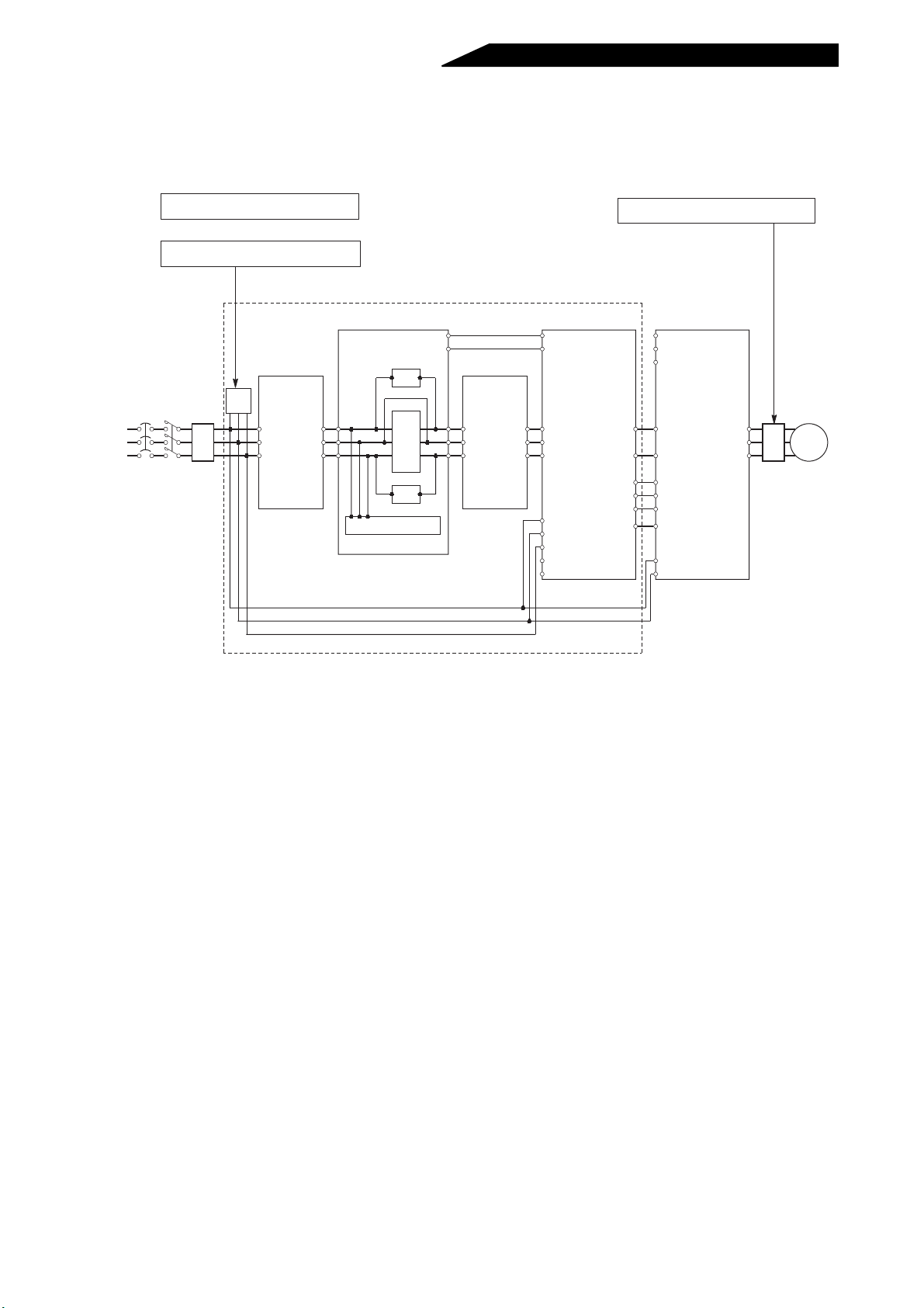
4) Using options to suppress noises
To suppress noises radiated by cables, the radio noise filter (FR-BIF) and line noise filter (FR-BLF) are available.
(Refer to page 68.) For more information, refer to the corresponding manual.
• Example (FR-A500)
Power
supply
NFB MC
Line noise filter (FR-BLF)
or
Radio noise filter (FR-BIF)
Reactor 1
(FR-HCL01)
FRBIF
R2
FRBLF
R
S
S2
T2
T
*2
*2
External box
(FR-HCB)
R2
S2
T2
Filter capacitor
Resistor
MC
Resistor
MC1
MC2
R3
S3
T3
Reactor 2
(FR-HCL02)
R4
R3
S4
S3
T4
T3
High power factor
converter(FR-HC)
MC1
MC2
R4
S4
T4
RDY
RSO
Y1 or Y2
R
S
T
R1
S1
*1
SE
Line noise filter (FR-BLF)
Inverter
(FR-A500 series)
R
S
T
P
P
N
N
X10
RES
X11
SD
R1
S1
U
FR-
V
W
BLF
Motor
*1
Keep terminals R1, S1 of the high power factor converter unconnected.
Inserting a filter in front of terminal R, S, T of the high power factor converter
*2
will produce more effective noise reduction. Refer to the noise filter manual
for installation procedure of the noise filter.
- 54 -
Page 67
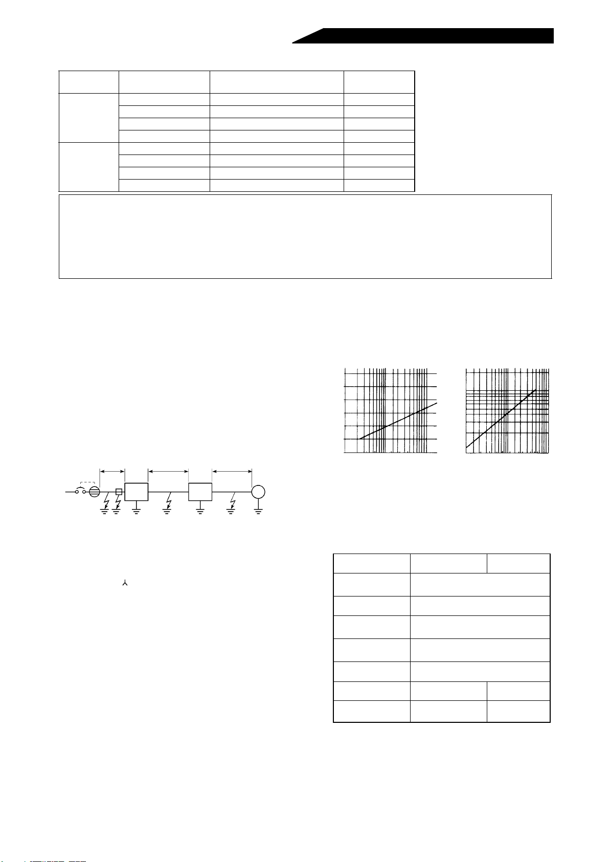
4.1.2 Peripheral device list
Voltage
200V class
400V class
High Powe r Factor
Converter T ype
FR-HC-7.5K 50AF 50A S-N35
FR-HC-15K 100AF 75A S -N65
FR-HC-30K 225AF 125A S-N125
FR-HC-55K 225AF 225A S-N220
FR-HC-H7.5K 30AF 30A S-N20
FR-HC-H15K 50AF 50A S-N25
FR-HC-H30K 100AF 75A S-N65
FR-HC-H55K 225AF 125A S-N125
No-fuse breaker (NFB note 1)
or leakage breaker (NV) (note 2)
Magnetic
Contactor (MC)
Note: 1.Select the NFB according to the capa city of the high power factor converter and install on e NFB
per high power factor converter.
2.For installations in the United States or Canada, the circuit breaker must be inverse time or
instantaneous trip type.
3. When the breaker on the primary side of the high power factor converter tripped, check for wiring
fault (e.g.short circuit), damage to internal parts of the inverter (high power factor converter), etc.
Identify the cause of the breaker trip, then power on the breaker after removing the cause of the trip.
4.1.3 Selecting the rated sensitivity current for the earth leakage circuit breaker
When using the earth leakage circuit breaker with the inverter circuit, select its rated sensitivity current as follows:
• Breaker for harmonic and surge
Rated sensitivity current: I n 10×(lg1+lg2+lg3+lgm)
>
∆
• Standard breaker
Rated sensitivity current:
>
In10×{lg1+lgn+lg2+3×(lg3+lgm)}
∆
where, lg1, lg2, lg3:leakage currents of cable path
during commercial power supply operation
lgn* :leakage current of noise filter on converter
input side
lgm :leakage current of motor during commercial
power supply operation
2
5.5mm
<Example>
NV
×5m 5.5mm2×50m 5.5mm2×70m
Noise
filter
High
power
factor
converter
lg1 lgn lg2 lg3
Inverter
3
φ
IM
200V 2.2kW
lgm
Note: 1.Install the NV on the primar y (power supply) side
of the power return common converter.
2.Ground fault on the o utput side of t he inverter can
be detected at the running frequency of 120Hz or
lower.
3.In the connection neutral point grounded system,
the sensitivity current becomes worse for ground
faults in the inverter secondary side. Hence, the
protective grounding of the load equipment should
be class C grounding (10 Ω or less).
4.When the breaker is installed in the secondary
side of the inverter, it may be unnecessarily
operated by harmonics if the effective value is
less than the rating. In thi s case, do not ins tall the
breaker since the eddy current and hysteresis
loss increase and the temperature rises.
5.The follo wing models are standard breaker s Type BVC1, BC-V, NVB, NV-L, NV-G2N, NV-G3NA, NV-2F
type leakage current relay (except for NV-ZHA), NV
Example of leakage curr ent per
1km in cable path during commercial power supply operation
when the CV cable is routed in
metal conduit (200V 60Hz)
120
100
80
60
40
Leakage current
20
(mA)
0
23.5
814223880150
5.5
Cable size (mm2)
30 60 100
Leakage Current Example of
3-Phase Induction Motor during Commercial Power Supply Operation (200V 60Hz)
2.0
1.0
0.7
0.5
0.3
Leakage current
0.2
(mA)
0.1
Selection Example
(for the diagram shown on the left) (mA)
Breaker for
harmonic and su rge
Leakage current lg1
(mA)
Leakage current lgn
(mA)
Leakage current lg2
(mA)
Leakage current lg3
(mA)
Motor leakage
current lgm (mA)
Total leakage current
(mA)
Rated sensitivity cur-
>
rent ( lg×10) (mA)
=
----------------- -
33× =0.17
1000m
0 (without noise filter)
----------------- -
33× =1.65
1000m
----------------- -
33× =2.31
1000m
4.31 7.97
30 100
1.5
3.7
7.5 15223755
2.2
5.5
1118.5 30 45
Motor capacity (kW)
Standard
Breaker
5m
50m
70m
0.18
with AA neutral wire open-phase protection
The following models are f or harmonic surge
NV -C/NV-S/MN series, NV30-F A, NV50-FA, BV-C2, leakage current alarm breaker (NF-Z), NV-ZHA, NV-H
* Note the leakage current value of the noise filter installed on the high power factor converter input side.
(For Mitsubishi’s dedicated filters, see page 71.)
- 55 -
Page 68

5. SPECIFICATIONS
This chapter offers details on the “specifications” of this
product.
Always read the precautions, etc. before starting use.
5
5.1 SPECIFICATIONS...................................................................................... 56
5.2 OPTIONS ................................................................................................... 68
Page 69
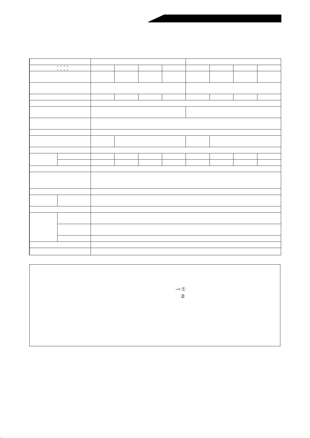
5.1 SPECIFICATIONS
5.1.1 Standard specifications
Input Voltage 200V Class 400V Class
Type FR-HC- 7.5K 15K 30K 55K H7.5K H15K H30K H55K
Applicable inverter
capacity (W)
Rated input voltage (V)
Rated input current (A) 33 61 115 215 17 31 57 110
Overload current rating 150% for 1 minute
Permissible power supply
voltage fluctuation
Permissible power supply
frequency fluctuation
Input power factor 0.99 or more (for load factor of 100%)
Protective structure
Cooling system Forced air cooling
Approx.
weight
Input signal Reset, converter stop, monitor switching
Output signal
Control system High carrier frequency sine-wave PWM control
Display
Protective function Power supply fault, overcurrent, device fault, undervoltage, transistor thermal relay (inverter protection)
Environment
Altitude 1000m or less below sea level
Vibration
Unit (kg) 8 15 29 70 9 16 35 72
Accessory (kg)* 20.3 30.8 66.6 96.3 22.7 31.9 51.3 93.3
Parameter
unit
Ambient
temperature
Ambient
humidity
Ambience Indoors. (No corrosive gases, flammable gases, oil mist, dust and dirt)
7.5K 15K 30K 55K 7.5K 15K 30K 55K
Three-phase 200V to 220V 50Hz
/200V to 230V 60Hz
170 to 242V 50Hz, 170 to 253V 60Hz 323 to 506V 50/60Hz
±5%
Enclosed
type IP20
Inverter run enable signal, converter operating, overload alarm, meter, alarm signal, reset,
multi-purpose (two signals selected from among power supply phase detection signal, voltage match,
instantaneous power failure detection, and driving/regenerative mode judgment) output
• Power supply frequency , input current, power supply voltage, input power, converter output voltage
• Eight alarm definitions are stored.
Open type IP00
-10°C to +50°C (non-freezing)
90%RH or less (non-condensing)
5.9m/s
2
Three-phase 380V to 460V 50/60Hz
Enclosed
type IP20
or less
Open type IP00
Note: 1.Select the model carefully.
When using inve rt ers wi th the h igh pow er fac tor conv er te r, the sum of all in ver ter ca pacit ies s hou ld
be within the applicable capacity:
Example: Inverter capacities applicable to FR-HC-15K FR-A520-15K
FR-A520-11K+FR-A520-3.5K
2.The 400V class high power factor converters are provided with H in their type codes.
3.The overload current rati ng % value indicates the ratio of the overlo ad current to the converter ’s
rated input current. F or repeated use, it is necessary to wait until the high power fac tor converter
and inverter return to less than the temperature under 100% load.
4.Storage temperature is applicable during a short period, e.g. in transit.
5.When the 400V class converter is used and the power supply voltage fluctuation is outside the
range 342V to 484V, the internal transformer setting must be changed. (Refer to page 24.)
- 56 -
Page 70
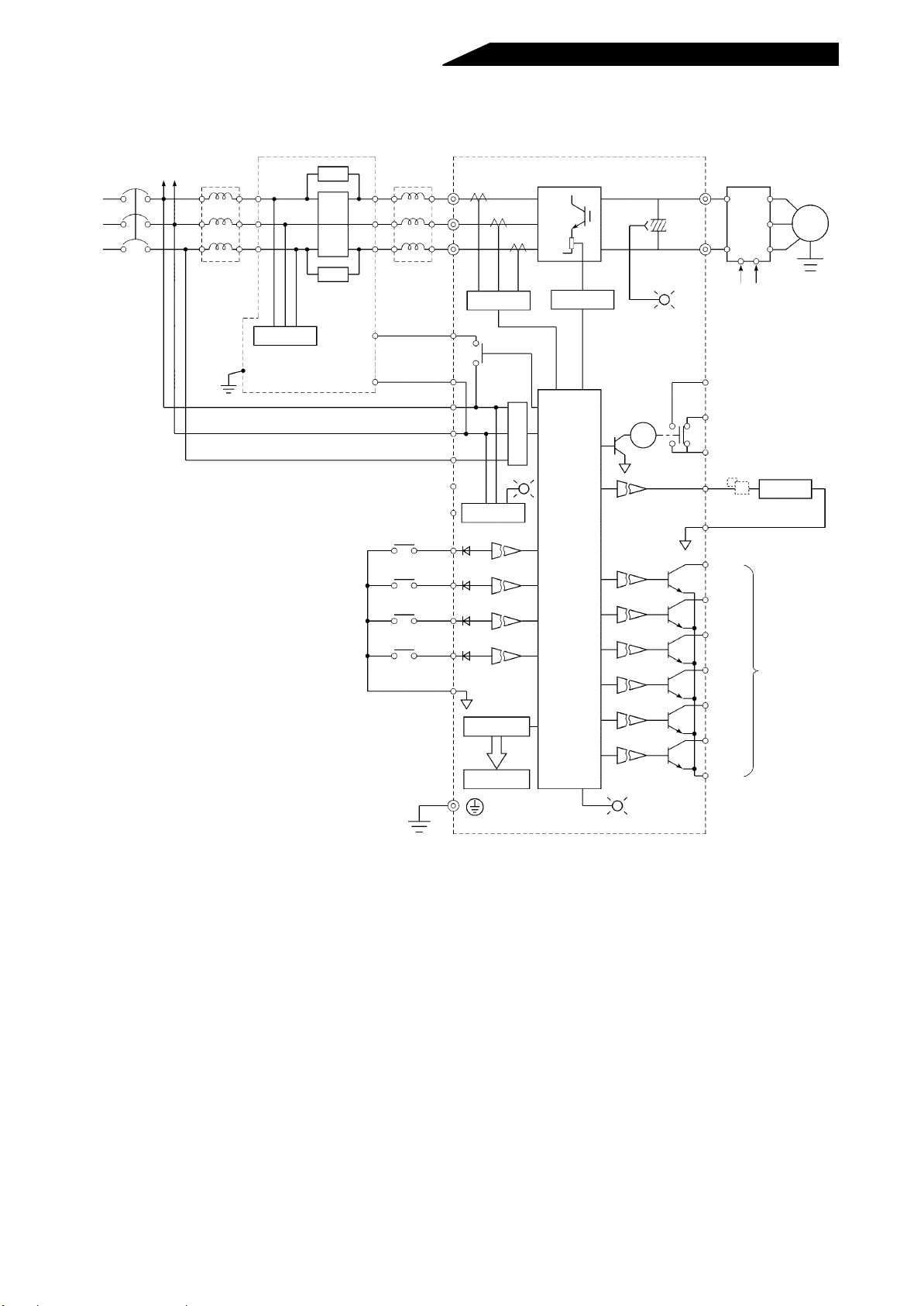
5.1.2 Block diagram
R1S1
FR-HCL01
R
S
Power supply
T
FR-HCB(Exlternal box) FR-HC (High power factor converter)
R2
S2
T2
R2
S2
T2
Filter C
R
MC
MC
R
MC1
R3
S3
T3
FR-HCL02
R3
S3
T3
R4
S4
T4
R4
S4
T4
MC1
Current
detection
Overcurrent
detection
CHARGE
Inverter
P
FR series
R1 S1
N
R1 S1 (Note 2)
Motor
M
MC2
Ground
(Note 1)
MC2
RES
SOF
X1
X2
SD
R
S
T
R1
S1
POWER
Control
power supply
CON
FR-PU02E
A
B
RA
Phase detection
CPU
-1
ALARM
C
FM
Calibration
resistor (Note 3)
SD
RDY
CVO
Y1
Y2
RSO
OL
SE
Meter
Open
collector
output
Note: 1.Keep terminals R1, S1 of the high power factor converter unconnected.
2.Except the FR-E500 and A024 series.
3.The parameter unit need not be used for calibration.
This resistor is used for calibration of a remotely located frequency
meter. Note that the needle of the frequency meter may not deflec t to
fullscale when the calibration resistor is connected. In this case, use
both the resistor and parameter unit to make calibration.
4.The R, S, T terminals of the high power factor converter (FR-HC) must
be connected to the power supply.
Running the inverter without connecting the terminals to the power
supply will damage the high power factor converter (FR-HC).
- 57 -
Page 71
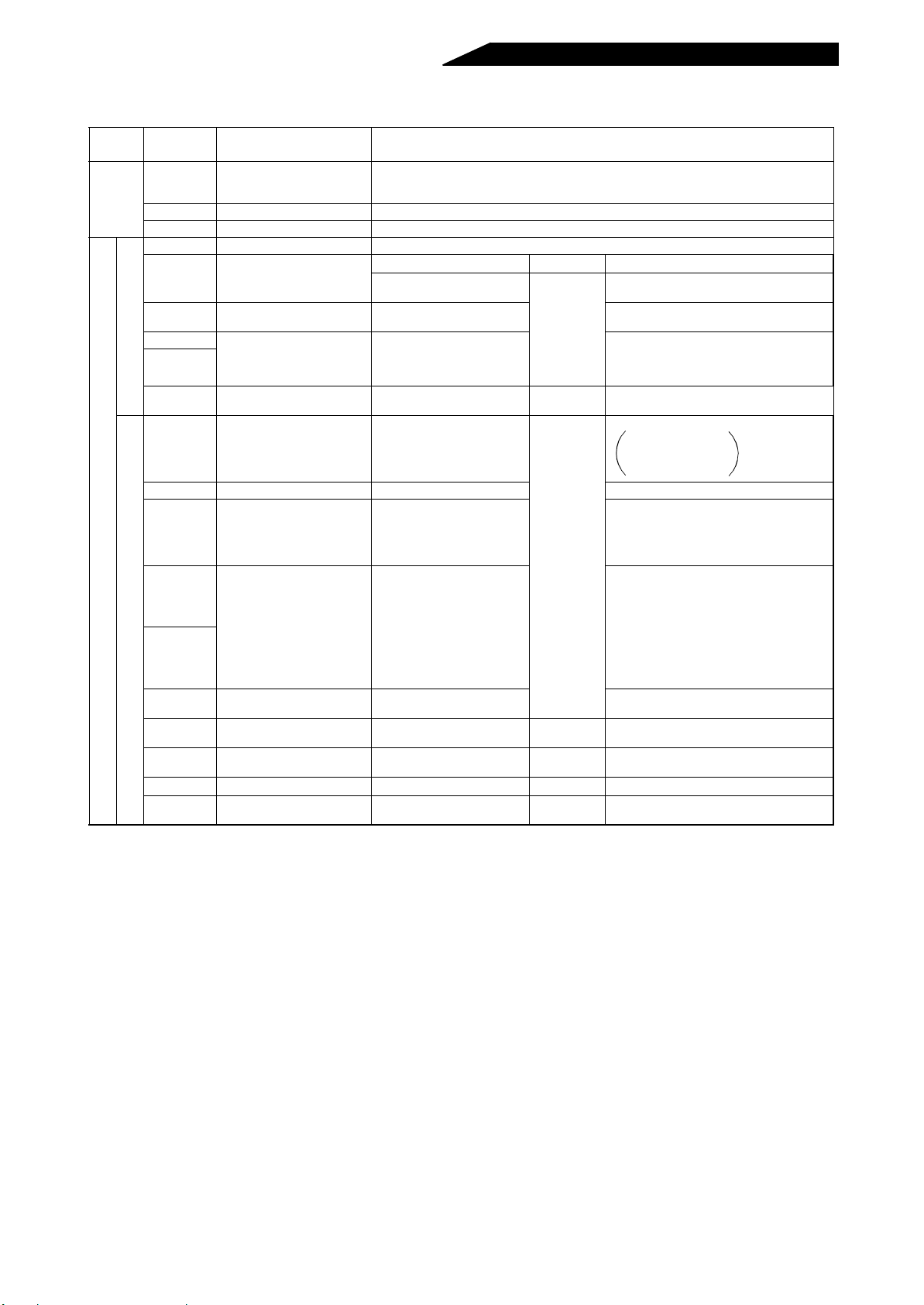
5.1.3 Terminals
Type
Main
circuit
Control ciruit
Terminal
Symbol
R, S, T Power input
R4, S4, T4 Power input Connect to reactor 2.
P, N Inverter connection Connect to P and N terminals of inverter.
MC1,CMC2 MC connection Connect to MC1, MC2 in external box.
Terminal Name Description
Ter minals for power supply ph ase, power voltage detection and control power input. Co nnect
to commercial power supply. Running the inverter without connecting these terminals will
damage the high power factor converter (FR-HC).
Function Circuit Remarks
RES Reset
SDF Converter stop C onverter gate shut-off
X1
Input signals
X2
SD Common terminal
RDY Inverter run enable signal
CVO Converter operating Output during IGBT switching
OL Overload alarm
Y1
Output signals
Y2
Monitoring switch-over
Multi-Purpose output
terminal
Converter operation stop
(used to return from error)
Selection of FM output and
PU monitor display
Common terminal
(input, FM)
Closed only when alarm
occurs or reset (RES) signal
is input.
Overcurrent
(150% load or more)
Overvoltage
(output at overvoltage
trip-less operation)
Multi-purpose output
External fault
24VDC
sink circuit
–
Open
collector
Operations of converter and all inverters
connected are stopped.
RDY signal is open.
Inrush MC is closed.
• Input current monitor
• Bus voltage monitor
• Input voltage monitor
• Input power monitor
Inverter is stopped.
RDY signal open:
Inverter operative
RDY signal closed:
Inverter inoperative
• Power supply
phase detection signal
• Output voltage match
signal detection
• Instantaneous power
failure detection
• Driving/regenerative
mode judgment
RSO Converter reset
FM Meter connection terminal
SE
SD Contact input common Common terminal (I/O, FM)
A, B, C Alarm conntact Alarm output
Open collector output
common
Output when converter is
reset.
Pulse train signal is output in
proportion to input current.
Open collector common
PWM pulse
output
–
–
Change-over
contact
Inverter is reset.
Depends on setting of X1, X2 terminals.
- 58 -
Page 72
Terminal Block for Control Circuit
A
B
Common to all models
Structure:2-stage molded
terminals
Screw size: M3
C
(NC)
(NC)
(NC)
(NC)
(NC)
(NC)
(NC)
SE
Y2
Y1
OL
RSO
CVO
RDY
SD
FM
SD
X2
X1
SOF
RES
PC
(NC)
(NC)
(NC)
(NC)
(NC)
(NC)
(NC)
Note: Terminals (NC) are free terminals. Keep them open.
Actually, no terminals symbols are printed on these
terminals.
- 59 -
Page 73
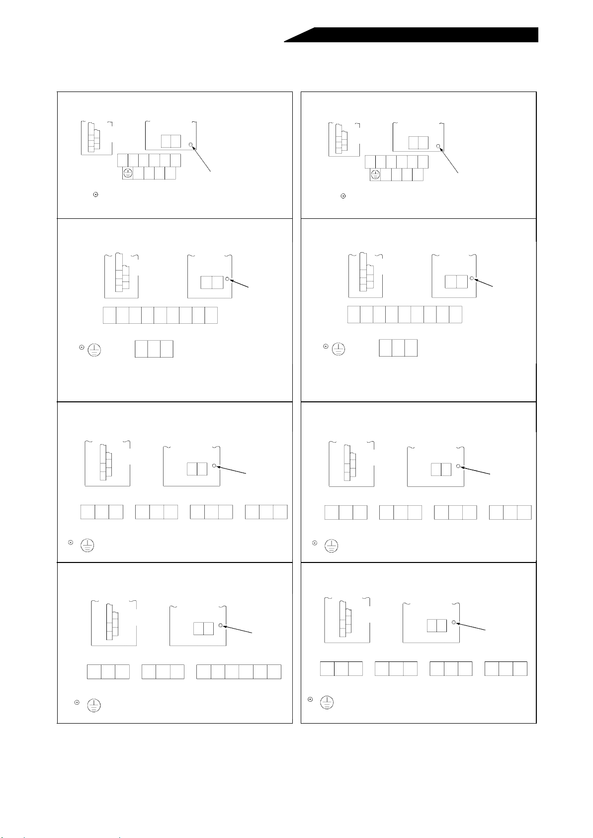
5.1.4 Terminal block arrangement
(1) 200V class (2) 400V class
FR-HC-7.5K FR-HC-H7.5K
Control circuit
terminal block
M4
R1S1
RSTR4S4T4
Screw size
Screw size
NP
Charge lamp (yellow)
MC1 MC2
M4
FR-HC-15K
Screw size
Control circuit
terminal block
Screw size M6
RSTR4S4T4N P
(M6)
Screw size M3.5
MC2
MC1 (NC)
•Terminals MC1, MC2 are located under the terminal
symbol cover. Connect terminals MC1, MC2 after
removing the terminal symbol cover.
M4
R1 S1
(NC)
Charge lamp
(yellow)
Control circuit
terminal block
M4
R1S1
RSTR4S4T4
Screw size
Screw size
NP
Charge lamp (yellow)
MC1 MC2
M4
FR-HC-H15K
Screw size
Control circuit
terminal block
Screw size M6
RSTR4S4T4N P
(M6)
Screw size M3.5
MC2
MC1 (NC)
•Terminals MC1, MC2 are located under the terminal
symbol cover. Connect terminals MC1, MC2 after
removing the terminal symbol cover .
M4
R1 S1
(NC)
Charge lamp
(yellow)
FR-HC-30K FR-HC-H30K
Screw size
Control circuit
terminal block
RST R4S4T4 N P
Screw size M4 Screw size M3.5 Screw size M8
(M6)
M4
R1 S1
MC2 (NC)MC1 (NC)
Charge lamp
(yellow)
RST R4S4T4 N P
Screw size M5 Screw size M3.5 Screw size M6
(M6)
FR-HC-55K FR-HC-H55K
Screw size
Control circuit
terminal block
RST R4S4T4N P
Screw size M4
(M6)
Screw size M3.5 Screw size M12
M4
R1 S1
MC2 (NC)MC1 (NC)
Charge lamp
(yellow)
RST R4S4T4 N P
Screw size M5 Screw size M3.5 Screw size M8
(M6)
Control circuit
terminal block
Control circuit
terminal block
Screw size
MC2 (NC)MC1 (NC)
Screw size
MC2 (NC)MC1 (NC)
M4
R1 S1
M4
R1S1
Charge lamp
(yellow)
Charge lamp
(yellow)
Note: Keep the control circuit terminals R1, S1 of the high power factor converter unconnected.
Note: Ter minals (NC) are fr ee terminals. Keep them open. Actually, no terminal symbols are printed on thes e
terminals.
- 60 -
Page 74

5.1.5 Outline drawings (400V class models have H in their type codes) (1) High power factor converter (FR-HC)
• FR-HC-7.5K, H7.5K
2-φ6 hole
* Parameter
unit installation position
(Unit: mm)
Protecti ve bush
• FR-HC-15K, H15K
* Parameter
unit installation position
195
220
230
250
300
285
210
View arrow
6
10
7.5
2-φ10 hole
380
400
10
190
190
2.3
242
View arrow
6
66
(Unit: mm)
80
• FR-HC-30K, 55K, H30K, H55K
* Parameter
unit installation position
C
W2
W
2-φC hole
H3
H2
H1
10
(Unit: mm)
D1
W1
View arrow
H
Inverter Type
FR-HC-30K, H30K 340 324 270 550 530 510 10 195 78 10
FR-HC-55K, H55K 480 464 410 700 675 645 15 250 130 12
3.2
D
W W1 W2 H H1 H2 H3 D D1 C
- 61 -
Page 75

(2) Reactor 1 (FR-HCL01), reactor 2 (FR-HCL02)
Make sure that the reactors 1 and 2 have the same capacity as the high power factor converter.
1) Reactor 1 (FR-HCL01)
• FR-HCL01-7.5K to 30K,
H7.5K to H55K
H
W1
W
4-φd
D1
D
• FR-HCL01-55K
RS
R2 S2 T2
W1
W
Terminal M12
T
H
4-φd
D
D1
190
(Unit:mm)
Approx.
Type H W W1 D D1 d
weight
(kg)
2 FR-HCL01-7.5K 155 160 145 100 58 5 3.3
0 FR-HCL01-15K 205 190 170 130 73 6 6.0
0 FR-HCL01-30K 230 220 200 170 88 6 10.8
V FR-HCL01-55K 260 210 165 225 160 8 21.0
4 FR-HCL01-H7.5K 150 160 145 100 65 5 4.2
0 FR-HCL01-H15K 195 190 170 130 80 6 7.2
0 FR-HCL01-H30K 215 220 200 140 90 6 12.0
V FR-HCL01-H55K 255 280 255 190 112 8 22.5
2) Reactor 2 (FR-HCL02)
• FR-HCL02-7.5K to 30K,
H7.5K to H55K
H
W1
W
4-φd
D1
• FR-HCL02-55K
D
With terminal
block cover
M12
H
H1
D
W1
W
4-φd
Type HH1WW1DD1d
2 F R-HCL02-7.5K 230
0 FR-HCL02-15K 270
0 FR-HCL02-30K 320
V FR-HCL02-55K 470 240 430 270 360 240 10 63.0
4 FR-HCL02-H7.5K 220
0 FR-HCL02-H15K 260
0 FR-HCL02-H30K 310
V FR-HCL02-H55K 380
240 210 160 110 7 12.8
–
260 230 170 120 7 20.5
–
340 310 180 130 10 37.0
–
240 210 160 110 7 13.8
–
260 230 170 120 7 20.5
–
340 310 180 130 10 35.0
–
400 270 285 240 10 60.0
–
D1
280
(Unit:mm)
Approx.
weight
(kg)
- 62 -
Page 76

3) Identification of the reactor 1 (FR-HCL01) and reactor 2 (FR-HCL02)
Each reactor has a rating plate. Connect the reactors 1 and 2 carefully. If they are connected in a wrong sequence,
they will be hot and it will be hazardous.
Rating plate
<Data on Rating Plates>
Reactor 1 (FR-HCL01) Reactor 2 (FR-HCL02)
AC REACTOR
TYPE FR-HCL01
BKO-CA
SERIAL
Note: Check this “TYPE” to discriminate between reactors 1 an d 2.
(Note)
AC REACTOR
TYPE FR-HCL02
BKO-CA
SERIAL
- 63 -
Page 77

(3) External box (FR-HCB)
Type H H1 W W1 D
FR-HCB-7.5K
2
FR-HCB-15K 4.7
0
0
FR-HCB-30K
V
FR-HCB-55K 12.6
FR-HCB-H7.5K
4
FR-HCB-H15K 4.7
0
0
FR-HCB-H30K 4.8
V
FR-HCB-H55K 450 435 270 200 203 9.9
320 305 190 130 165
450 435 270 200 203
320 305 190 130 165
1) Outline
Wiring hole
2-pear-shaped
hole M6
8
(Unit: mm)
Approx.
weight
(kg)
4.7
9.7
5.7
H1
H
Pear-shaped
Rating
plate
7
W1
W
7
2.3
D
hole details
7
13
10
- 64 -
Page 78

2) Terminal bloc k
(a) FR-HCB-7.5K/15K/H7.5K/H15K/H30K
<Terminal layout>
S2
TB1
T2R2
R3
S3
T3
(b) FR-HCB-30K/55K/H55K
<Terminal layout>
TB1
S2
T2R2
TB2
MC1 (NC) MC2
GND
TB2
MC1 (NC) MC2
<Terminal screw size>
Type TB1 TB2 GND
FR-HCB-7.5K/H7.5K
FR-HCB-15K/H15K/H30K
<Terminal screw size>
Type TB1 TB2 GND
FR-HCB-30K M6 M3. 5 M6
FR-HCB-55K/H55K M8 M3.5 M6
M5 M3.5 M5
GND
R3
S3
T3
Note: Terminals (NC) are free terminals. Keep them open. Actually, no terminal symbols are printed on these
terminals.
- 65 -
Page 79

5.1.6 Panel cutting dimension diagrams (For use of the heat sink outside mounting attachment)
(
)
(
)
•FR-HC-7.5K/H7.5K •FR-HC-15K/H15K
High power factor
converter outline
300
9.5
4-M5 screw
195
212
High power fact or
320
305
•FR-HC-30K, 55K/H30K, H55K
converter outline
H7
Unit: mm
W2
High power fact or
converter outline
N-C screw
H3
H5
H6
H1
H4
6-M8 screw
200
90
102
244
400
19.5
230
260
40
335
440
40
12.5
(Unit: mm)
H8
W3
W1
H2
Unit: mm
Inverter T ype W 1 W2 W3 H1 H2 H3 H4 H5 H6 H7 H8 N C
FR-HC-30K, H30K 330 265 290 516 12 95 540 85 – 510 15 6 M8
FR-HC-55K, H55K 470 390 430 650 15 70 ––730 645 24.5 4 M10
- 66 -
Page 80
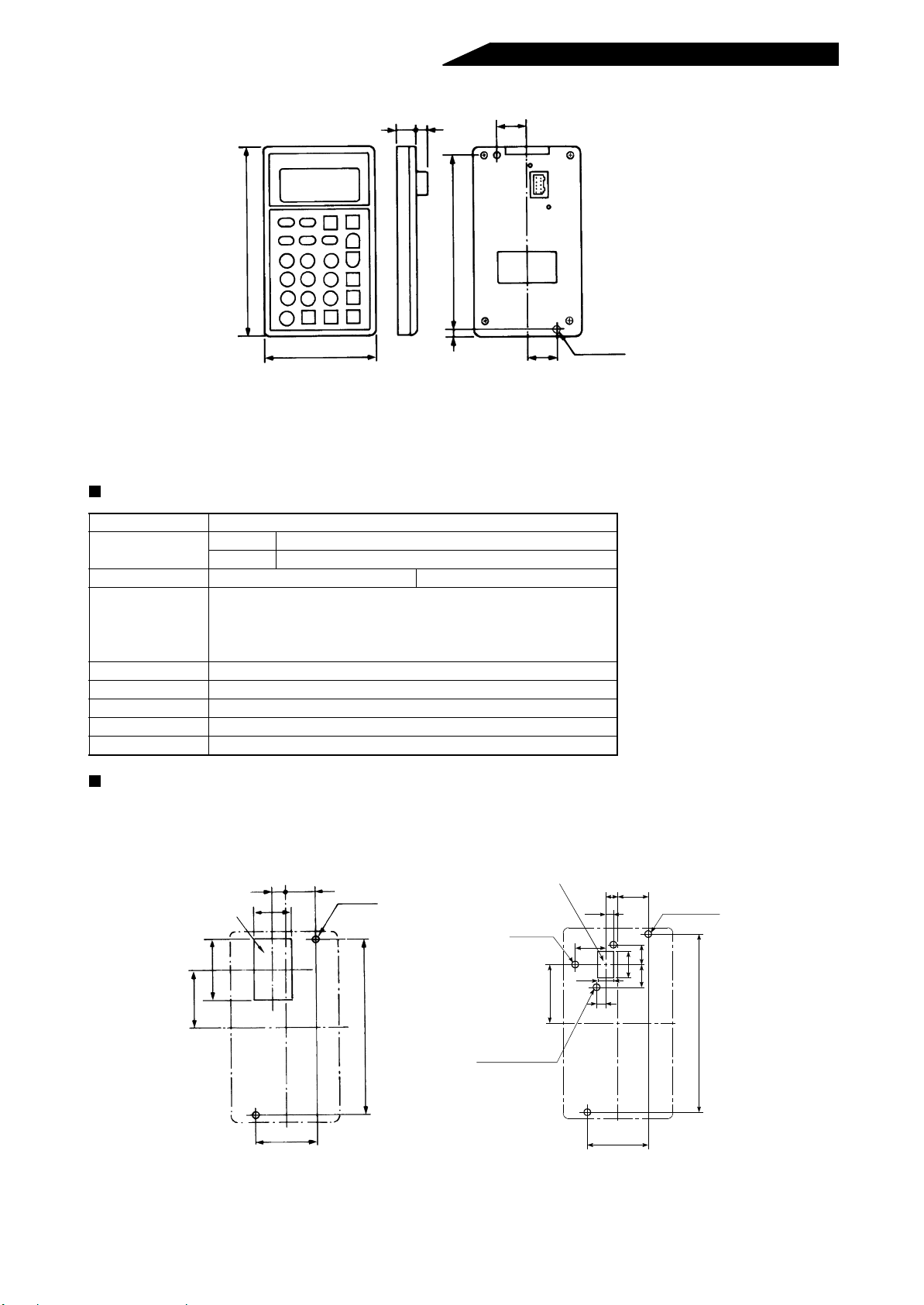
5.1.7 Parameter unit (FR-PU02-1/FR-PU02E-1/FR-PU02ER-1) dimension diagram
12 7
20
127
70
117
5
20
Note: The length of the installation screw should be selected so that it
does not exceed the effective installation screw depth of the
parameter unit.
FR-PU02E-1 Specifications
Item Specifications
Ambient
temperature
Ambient humidity 90%RH Non-condensing
Operating ambience No oil mist and corrosive gases. Minimal dust and dirt.
Power supply Power is supplied from the inverter.
Connection Loaded to the inverter directly or connected by the cable.
Display LCD (liquid crystal display , 13 characters × 4 lines)
Keyboard 24 keys (covered with polyurethane film)
Size 127 (H) × 70 (W) × 12 (D)
Operating -10 to +50°C (Note 1) Note: 1. When the temperature is
Storage -20 to +65°
C
2-M3 screw
Effective depth 4.5
(Unit: mm)
less than about 0°C, the
liquid crystal display (LCD)
may be slower in operation.
And high temperature may
reduce the LCD life.
2. Do not expose the liquid
crystal display directly to
the sun.
Panel cutting dimensions for installation of the parameter unit to a panel or the like
• Parameter unit cable (straight type) is
used and is not fixed to the panel
Panel cut portion
42
(38.5)
820
24
40
2-φ4 hole
117
(View as seen from the parameter unit)
• Parameter unit cable (L type) is used
and fixed to the panel
Panel cut portion
4 hole
φ
2-φ3.5 hole
6 countersunk
φ
20
10.5
38.5
208
5
1315
17
6
40
2-φ4 hole
117
(Unit: mm)
- 67 -
Page 81
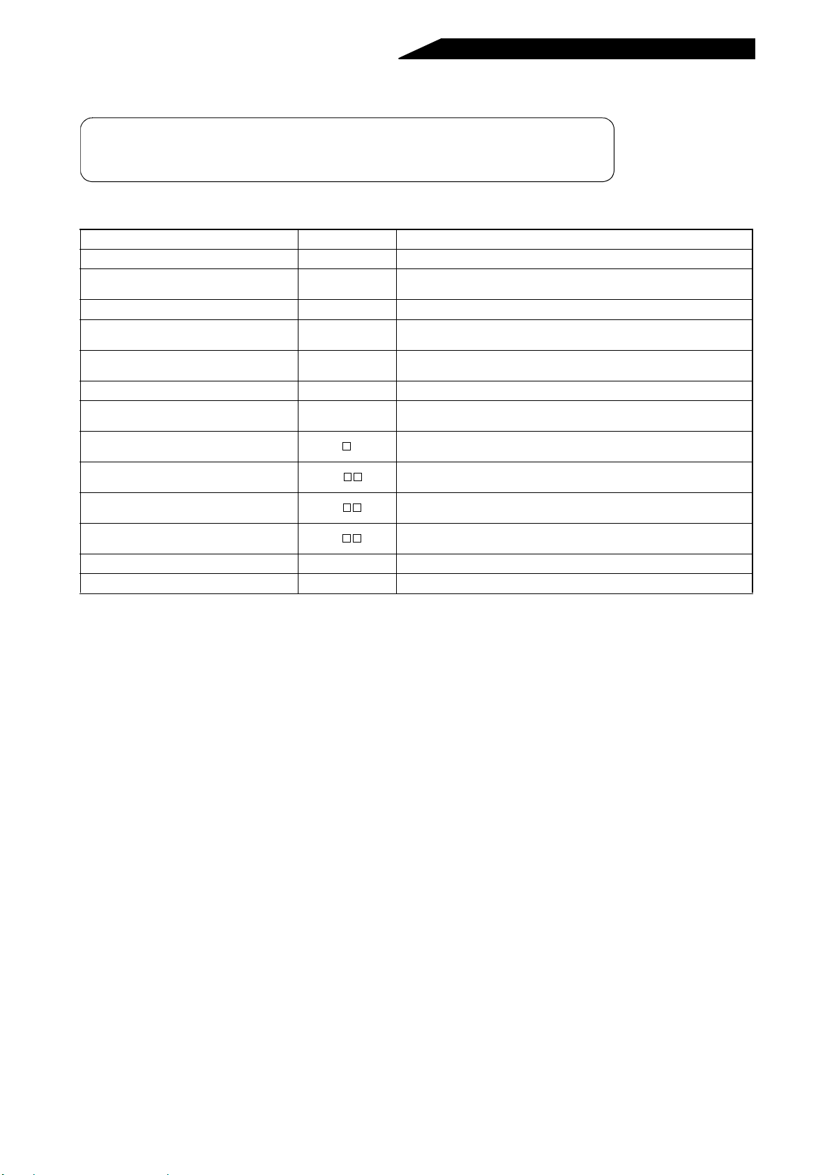
5.2 OPTIONS
By using the following options, the functions of the high power factor converter can
be increased. Make a correct selection.
The following options are all external dedicated option units.
5.2.1 Option list
Name Type Application, Specifications, Etc.
Parameter unit (Japanese) FR-PU02
Parameter unit (English) FR-PU02E
Parameter unit (4 languages) FR-PU02ER
Parameter copy unit (Japanese) FR-ARW
Parameter copy unit (English) FR-ARWE
Parameter copy unit (4 languages) FR-ARWER
Accessory cover
Parameter unit cable
Heat sink outside mounting attachment
Dirt-protection structure attachm ent
Conduit connection attachment
Radio noise filter FR-BIF-(H)* For radio noise reduction
Line noise filter FR-BLF For line noise reduction
FR-CBL
FR-ACN
FR-ACV
FR-AFN
-1
-1
-1
-1
-
Interactive parameter unit using LCD display
The LCD display and ten-key pad of the FR-PU02
English.
For use in English, German, French and Spanish.
-1
Allows parameter settings to be read in batch and copied to the other
converter.
The LCD display and ten-key pad of the FR-ARW-1 are indicated in
English.
For use in English, German, French and Spanish.
-1
Blind cover fitted after the parameter unit is removed from the
converter.
Cable for connection of the parameter unit or parameter copy unit.
Straight or L types are available.
Used to place only the heat generating section of the high power factor
converter in the back of the control box.
By installing this option, the high power factor converter meets the
totally enclosed structure specifications (IP40).
Used to connect a conduit pipe directly to the high power factor
converter. (IP20)
are indicated in
-1
* 400V class models have H in their type codes.
Note: Not all options are available in all countries, please refer to your Mitsubishi distributor.
- 68 -
Page 82
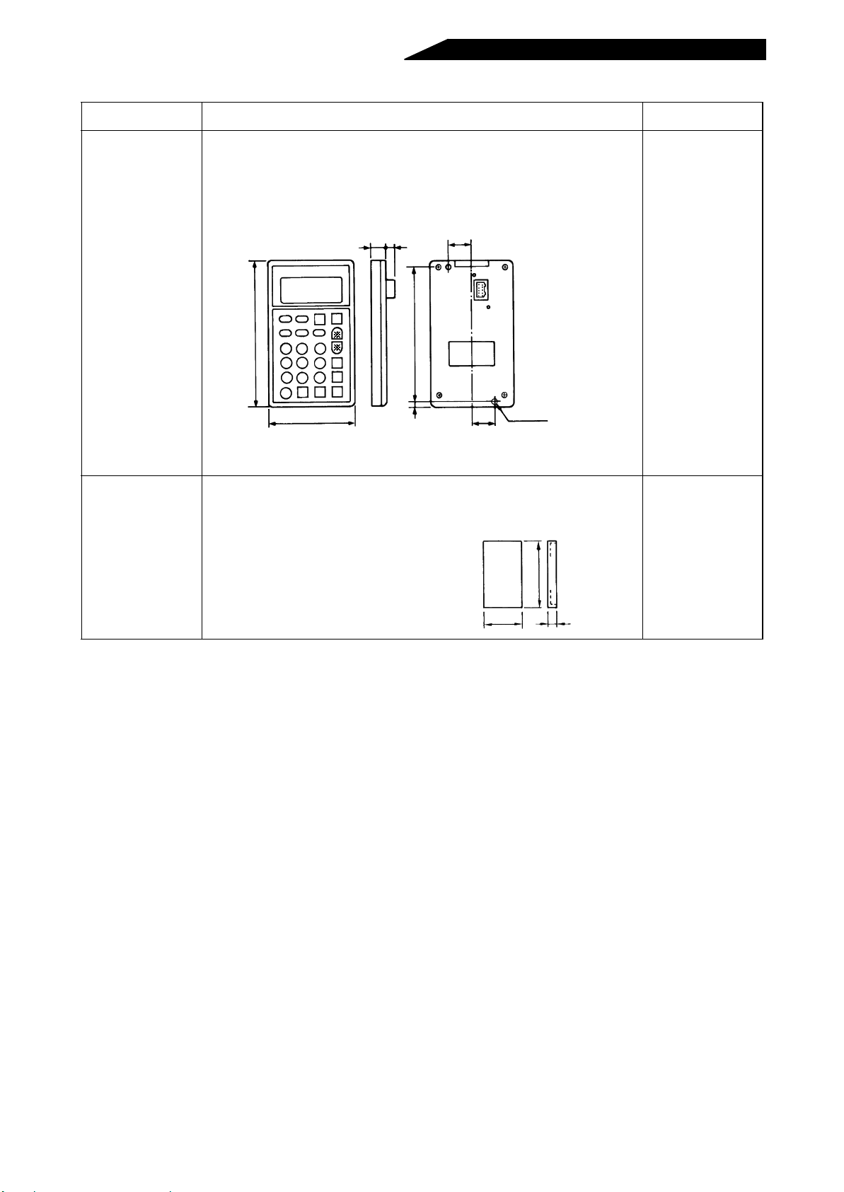
5.2.2 External dedicated options
(E)
Name (Type) Specifications, Structu re, Etc. Remarks
Parameter copy unit
FR-ARW
-1
(Japanese)
FR-ARWE
-1
(English)
FR-ARWER
-1
(4 languages)
• Allows parameters set to application t o be read in batch and easily written to another
high power factor converter.
• LCD and ten-key pad representations are available in three ways: Japanese, English
and four languages (English, German, French, Spanish).
• Outline dimensions are the same as those of the FR-PU02
parameter unit.
-1
• Can also be used as the parameter unit.
12.7
20
(Unit: mm)
127
70
* The keys marked have different functions
from those for the FR-PU02
117
5
2-M3 screw
20
Ettective depth 4.5mm
-1
.
Accessory cover • When the parameter unit is removed from the high power factor converter, this cover
is fitted to that position. ποσιΑτιον
• This cover can be fitted and removed by a single action.
(Unit: mm)
127
70 12
This cover is supplied
to the model which is
not equipped with the
parameter unit.
- 69 -
Page 83
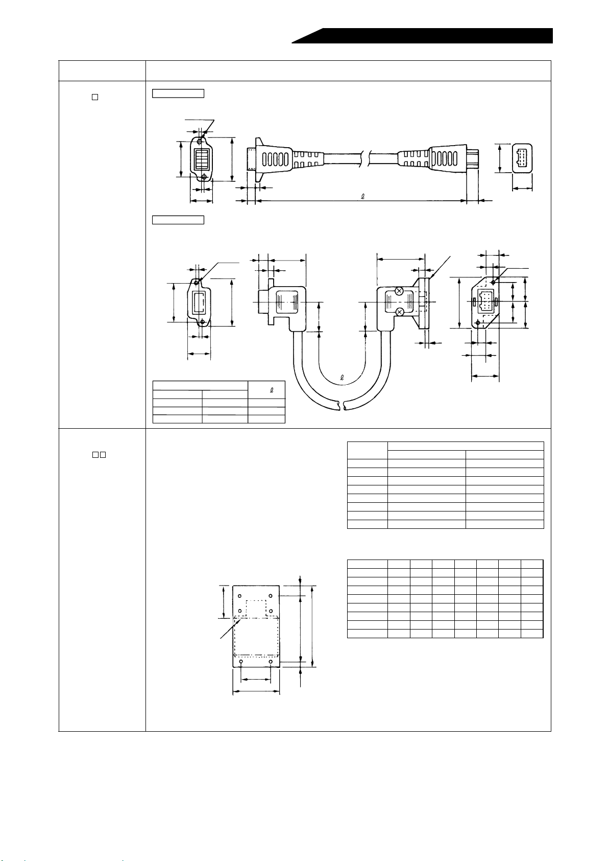
Name (Type) Specifications, Structure, Etc.
n
Parameter unit cable
FR-CB L
Straight type
High power factor converter side
2-φ3.5
2
(Unit: mm)
Parameter unit side
Heat sink outside
mounting attachment
FR-ACN
26
L shape type
2
26
32
2
15
2-φ3.5
CBL 01
+1
6
-0
High power factor converter side
3
+1
6
-0
25
3
32
CBL-L1
20
2
16
Straight
FR-CBL01
FR-CBL03
FR-CBL05
Type
FR-CBL-L1
FR-CBL-L3
FR-CBL-L5
Length (m)
L
1
3
5
• By using this attachment, the heat sink acting as
the heat generator of the high power factor
converter can be placed at the back of the control
box. Since the converter-generated heat can be
dissipated to the outside of the control box, the
control box can be made compact.
• For the mounting state and panel cut dimensions,
see the outline drawing (page 66).
Note: Since the cooling fan exists in the cooling
section placed out of the box, do not use
this attachment in environments subjected
to water drops, oil mist, dust, etc.
Dimensions after mounting
of the attachment
H4
High power factor
converter outline
H2
H1
H
20
15
9
Parameter un it si de
(Removable)
32.5
3.5
Spacer
35
20
(2.3)
The PU side connector of this L type cable ca
be fixed with the accessory screws.
Type
FR-ACN01
FR-ACN02
FR-ACN03 FR-HC-7.5K FR-HC-H7.5K
FR-ACN04 FR-HC-15K FR-HC-H15K
FR-ACN05
FR-ACN06 FR-HC-30K FR-HC-H30K
FR-ACN07
FR-ACN08 FR-HC-55K FR-HC-H55K
Type W W1 H H1 H2 H3 H4
FR-ACN01 150 125 336 320 8 8 17
FR-ACN02 150 125 336 320 8 8 17
FR-ACN03 220 195 336 320 8 8 17
FR-ACN04 280 230 554 530 12 12 122
FR-ACN05 330 280 604 580 12 12 122
FR-ACN06 340 290 682 625 19 38 122
FR-ACN07 460 410 625 590 15 20 80
FR-ACN08 490 430 775 730 17 28 80
Applicable High Power Factor Converter
200V class 400V class
––
––
––
––
9.5
8.5
5
2-φ3.5
13
16.5
15
18.5
6
18
(Unit: mm)
W1
W
H3
- 70 -
Page 84
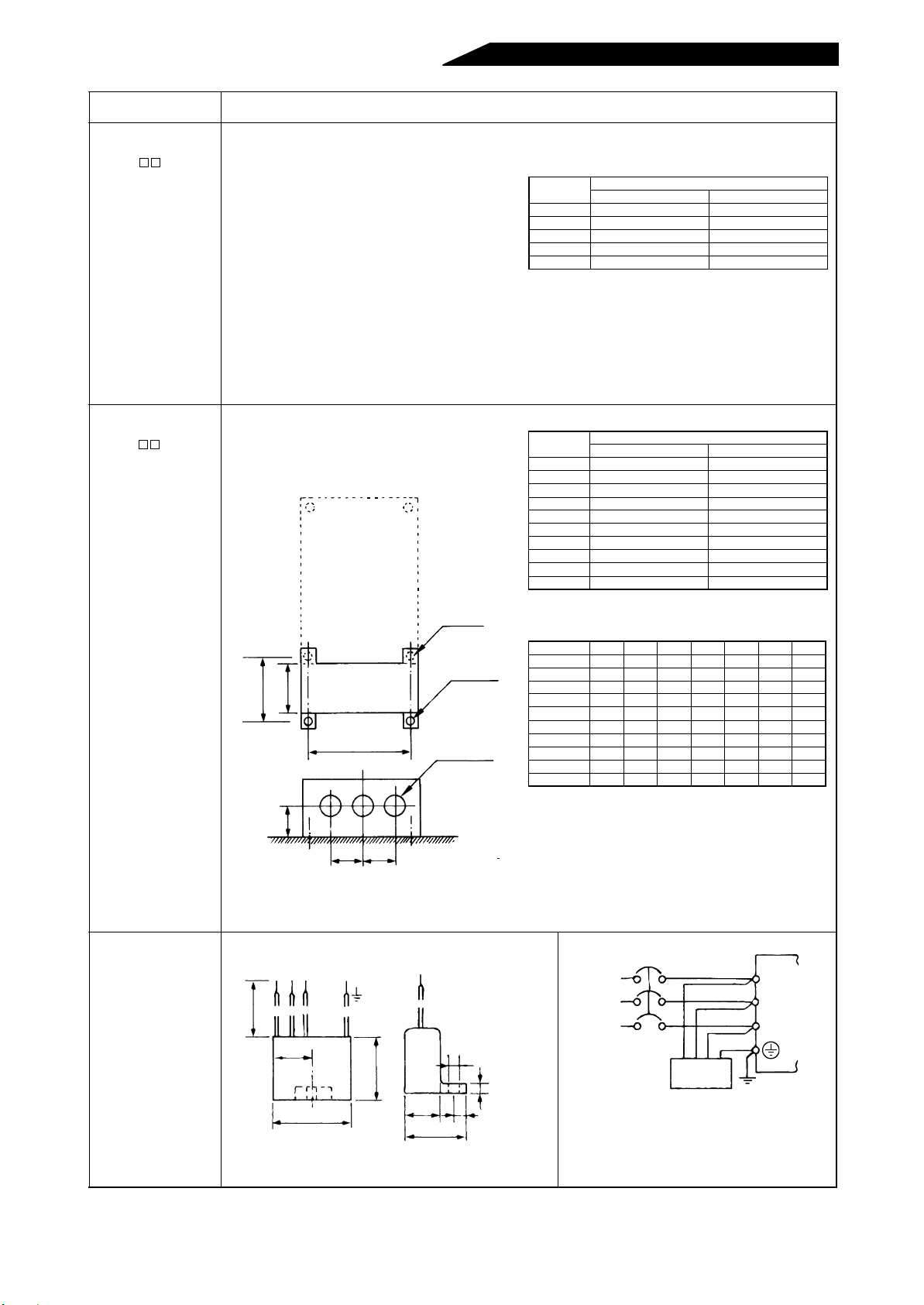
Name (Type) Specifications, Structure, Etc.
Dirt-protection
structure attachment
FR-ACV
• By installing this option in the slits at the top,
bottom, right and left of the high power factor
converter, the high power factor converter can be
changed to be an enclosed structure model (IP40).
(The box-shaped attachment is added to the wiring
section of 11K to 22K.)
• Adequate for wall mounting application, etc.IP40
(JEM1030): Structure which prevents a wire,
copper band or the like in excess of 1mm in
diameter or thickness from entering into the high
Type
FR-ACV01
FR-ACV02
FR-ACV03 FR-HC-7.5K FR-HC-H7.5K
FR-ACV04 FR-HC-15K FR-HC-H15K
FR-ACV05
power factor converter.
Note 1: T his struc ture is not protected from water and
fluid entry and is therefore not appropriate for
environments often exposed to water drops
or oily smoke.
Note 2:When this attachment is used, the
per miss ible am bient temperature of the high
power factor converter is -10°C to +40°C.
Conduit connection
attachment
FR-AFN
• Used to connect a conduit pipe directly to the
bottom of the high power factor converter.
• By installing this attachment, 11K to 55K (200V,
400V) are changed in structure specification to
IP20. (IP00 is standard.) .
High power factor converter
Type
FR-AFN01
FR-AFN02
FR-AFN03
FR-AFN04
FR-AFN05 FR-HC-7.5K FR-HC-H7.5K
FR-AFN06 FR-HC-15K FR-HC-H15K
FR-AFN07
FR-AFN08 FR-HC-30K FR-HC-H30K
FR-AFN09
FR-AFN10 FR-HC-55K FR-HC-H55K
Applicable High Power Factor Converter
200V class 400V class
––
––
––
Applicable High Power Factor Converter
200V class 400V class
––
––
––
––
––
––
Radio noise filter
FR-BIF 200V class
FR-BIF-H
400V class
(Note)
2-φR hole
M
L
H
FR-AFN
*
PP
N-φD hole
(with rubber bush)
(Installation pan el surface)
Note: Secured by a total of four places, the two
installation screws at the bottom of the high
power factor converter and the two places at
the bottom of the FR-AFN.
5 hole
φ
(Unit: mm)
4
White
Red Blue Green Leakage current:4mA
Approx. 300
29
42
Attachment Outline Drawing (Unit: mm)
Type L H P N D M R
FR-AFN01 45 56 48 2 35 60 6
FR-AFN02 45 71 48 2 35 60 6
FR-AFN03 45 75 48 3 35 60 6
FR-AFN04 45 115 48 3 35 60 6
FR-AFN05 55 115 60 3 44 70 6
FR-AFN06 70 115 68 3 50 90 10
FR-AFN07 145 115 68 4 50 185 10
FR-AFN08 145 95 68 4 50 102.5 10
FR-AFN09 285 120 113 3 91 227.5 12
FR-AFN10 285 120 113 4 91 227.5 12
* Same dimensions as those of the high power factor converter.
NFB
Power
supply
FR-BIF
Reactor 1
R
S
T
58
29 7
44
Note: 1. This filter must not be connected to the
output circuit of the high power factor
converter.
2.The cables should be as short as
possible and connected to the terminal
block of the high power factor converter.
- 71 -
Page 85

Name (Type) Specifications, Structure, Etc.
Line noise filter
FR-BLF
31.580
7
φ
35
2.3
* (H) in a type code indicates that the unit is for 400V.
FR-BLF
130
85
160
180
(Unit: mm)
7
NFB
Power
supply
Line noise filter
Note:1.Wind the cable 4 or more times in the same
direction in each phase. (A greater effect is
produced as the winding times increase.)
2.If the cable size is too large to wind , use four or
more filters in series and win d the cable in the
same direction in each phase.
3.This filter can also be used on the output s ide
as on the input side. The winding on the output
side should be within 3 turns.
Reactor 1
R
S
T
- 72 -
Page 86

APPENDIX
This chapter provides an “supplementary information” of
this product.
Always read the precautions, etc. before starting use.
APPENDIX 1 INSTRUCTIONS FOR COMPLIANCE WITH THE EUROPEAN
STANDARDS................................................................................ 73
APPENDIX 2 Instructions for UL and cUL........................................ .............. 74
Page 87

APPENDIX 1 INSTRUCTIONS FOR COMPLIANCE WITH THE EUROPEAN
STANDARDS
(The products conforming to the Low Voltage Directive carry the CE mark.)
Low Voltage Directive for FR-HC series (High power factor converters)
(1) Our view of the FR-HC series for the Low Voltage Directive.
The FR-HC series is covered by the Low Voltage Directive ( DIN VDE0160 ).
(2) Compliance
* We have self-confirmed the FR-HC series as products compliant to the Low Voltage Directive.
* Since the FR-HCB box, FR-HCL01 reactor and FR- HCL02 reactor a re considered p ar ts of the FR- HC
unit and we place the CE mark on the FR-HC unit.
(3) Outline of instruction
* In the FR-HC-H series (40 0V class ), the rated in put voltage range is three -phase, 380 V to 415V, 50Hz/
60Hz.
* Connect the equipment to the earth securely. Do not use an earth leakage circuit breaker as an electric
shock protector without connecting the equipment to the earth.
* Wire the earth terminal independently. (Do not connect two or more cables to one terminal.)
* The wire size for PVC cables are shown for the following conditions;
Ambient Temperature: 40°C maximum
Wire installation: On wall without ducts or conduits
If conditions are different from ab ove, select appropria te wire accord ing to E N60204 A NNEX C, TABL E
5.
* On the input side, use the recommended no-fuse breaker and magnetic contactor which conform to the
EN or IEC standard.
* Use the FR-HC un it, including th e FR-HCB box and the react ors, under the condit ions of overvoltage
category II and contamination lev el 2 or less set forth in IEC664.
(a) To meet the overvoltage categor y II, inser t an EN or IEC stand ard-compliant isolat ion transformer
or surge suppressor in the input of the FR-HC (FR-HCL01 reactor).
(b) To meet the con tamination level 2, install the FR -HC unit, the FR-HCB box and the r eactors in a
control box protected against ingress of water, oil, carbon, dust, etc. (IP54 or higher).
* The operating capaci ty of the relay outputs (termina l symbol A, B, C) should be 30VDC, 0.3A. ( The
relay outputs are basically isolated from the terminal circuitry of the FR-HC unit.)
- 73 -
Page 88
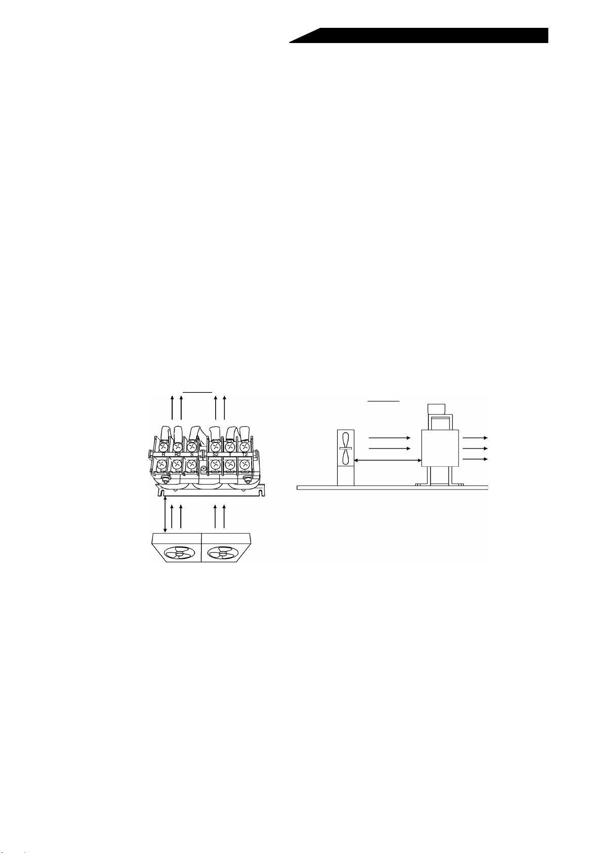
APPENDIX 2 Instructions for UL and cUL
(Standard to comply with: UL 508C, CSA C22.2 No. 14)
1. General Precaution
The bus capacitor discharge tim e is 10 minutes. Before starting wiring or inspec ti on, switch power off, wait
for more than 10 minutes, and check for residual voltage between P and N with a meter etc., to avoid a
hazard of electrical shock.
2. Installation
(1) T he FR-HC units have been approved as products for use in an enclosure. Please refer to the following
UL’s requirement for the enclosure.
* The minimum enclosure size is 150 pe rce nt of ea ch conver ter an d inverter combination, whic h mus t be
provided with ventilation openings on each side near the top.
* The minimum area for the ventilatio n openings must be 55 percent of th e overall surface area of each
side and be located i n the top quarter of the s ide. The maximum width of eac h individua l vent must be
3.17mm (1 / 8 in.).
(2) The FR-HC-H55K have been approved on the following condition.
* A 2.8 m
H55K.
*Two 2.8 m
the following illustrations.
3
/min {100 cfm } fan must be used space d 10cm (4 in.) ab ove the FR-HC-H55K and FR-HCB-
3
/min {100 cfm } fans for air ci rculation for the FR-HCL02 -H55K must be used as shown in
Top view
10 to 20 cm
(4 to 8 in.)
Front view
10 to 20 cm
(4 to 8 in.)
3. Branch circuit protection
For installation in United States, branch circuit protection must be provided, in accordance with the
National Electrical Code and any applicable local codes.
For installation in Canada, branch circuit protection must be provided in accordance with the Canada
Electrical Code and any applicable provincial codes.
4. Short circuit ratings
Suitable For Use in A Circuit Capable Of Delivering Not More Than 5 kA r ms Symmetr ical Ampere s, 500
Volts Maximum.
5. Wiring
When wiring t he I/O terminals and control circuit, use UL-approved, 75°C or higher rated copper wires
and round crimping terminals and screw them to the specified tightening torque . Crimp the crimping
terminals with the crimping tool recommended by the terminal maker.
- 74 -
Page 89
REVISIONS
* The manual number is given on the bottom left of the back cover.
Print Date
Dec., 1996 IB(NA)66718-A First edition
Mar., 2001 IB(NA)66718-B
Apr., 2003 IB(NA)66718-C
Sep., 2008 IB(NA)66718-D
*Manual Number
Additions
• Applicable inverters
• Instructions for Compliance with the European Standards
(Appendix 1)
• Instructions for Compliance with U.S. and Canadian Electrical Codes
(Appendix 2)
Partial additions
•Wiring
Partial additions
• Not e for terminal connection diagram
Partial changes
• Converter reset
Revision
IB(NA)66718-D
- 75 -
 Loading...