

Mitsubishi FR-A540-0.4K-55K, FR-A540-0.4K, FR-A520-0.4K-55K-NA, FR-A540-0.4K-55K-NA, FR-A500 Instruction Manual
...
Artisan Technology Group is your source for quality
new and certied-used/pre-owned equipment
• FAST SHIPPING AND
DELIVERY
• TENS OF THOUSANDS OF
IN-STOCK ITEMS
• EQUIPMENT DEMOS
• HUNDREDS OF
MANUFACTURERS
SUPPORTED
• LEASING/MONTHLY
RENTALS
• ITAR CERTIFIED
SECURE ASSET SOLUTIONS
SERVICE CENTER REPAIRS
Experienced engineers and technicians on staff
at our full-service, in-house repair center
WE BUY USED EQUIPMENT
Sell your excess, underutilized, and idle used equipment
We also offer credit for buy-backs and trade-ins
www.artisantg.com/WeBuyEquipment
REMOTE INSPECTION
Remotely inspect equipment before purchasing with
our interactive website at www.instraview.com
LOOKING FOR MORE INFORMATION?
Visit us on the web at www.artisantg.com for more
information on price quotations, drivers, technical
specications, manuals, and documentation
Contact us: (888) 88-SOURCE | sales@artisantg.com | www.artisantg.com
SM
View
Instra

HIGH FUNCTION
&
LOW ACOUSTIC NOISE
FR-A500
TRANSISTORIZED INVERTER
– INSTRUCTION MANUAL –
FR-A520-0.4K to 55K(-NA)
FR-A540-0.4K to 55K(-NA)(-EC)
Artisan Technology Group - Quality Instrumentation ... Guaranteed | (888) 88-SOURCE | www.artisantg.com
A - 1
Thank you for choosing this Mitsubishi transistorized Inverter.
This instruction manual gives handling information and precautions for use of this
equipment.
Incorrect handling might cause an unexpected fault. Before using the inverter, please read
this manual carefully to use the equipment to its optimum.
Please forward this manual to the end user.
This section is specifically about safety matters
Do not attempt to install, operate, maintain or inspect the inverter until you have read through this
instruction manual and appended documents carefully and can use the equipment correctly.
Do not use the inverter until you have a full knowledge of the equipment, safety information and
instructions.
In this instruction manual, the safety instruction levels are classified into “WARNING” and “CAUTION”.
Assumes that incorrect handling may cause hazardous conditions, resulting in
death or severe injury.
Assumes that incorrect handling may cause hazardous conditions, resulting in
medium or slight injury, or may cause physical damage only.
Note that the CAUTION level may lead to a serious consequence according to conditions. Please follow
the instructions of both levels because they are important to personnel safety.
CAUTION
WARNING
Artisan Technology Group - Quality Instrumentation ... Guaranteed | (888) 88-SOURCE | www.artisantg.com
A - 2
SAFETY INSTRUCTIONS
1. Electric Shock Prevention
WARNING
z
While power is on or when the inverter is running, do not open the f ront c over. You m ay get an electric
shock.
z
Do not run the inverter with the front cover removed. O therwise, you may access the exposed highvoltage terminals or the charging part of the circuitry and get an electric shock.
z
If power is off, do not remove the f ront cover except f or wiring or periodic inspection. You may access
the charged inverter circuits and get an electric shock.
z
Before starting wiring or inspection, switch power off, wait for more at least 10 minutes and c heck for
the presence of any residual voltage with a meter (check chapter 2 for further details.) etc.
z
Use class 3 (200V) or special class 3 (400V) or higher earthing method to earth the inverter.
z
Any person who is involved in the wiring or inspection of this equipment should be fully competent to do
the work.
z
Always install the inverter before wiring. Otherwise, you may get an electric shock or be injured.
z
Operate the switches with dry hands to prevent an electric shock.
z
Do not subject the cables to scratches, exc ess ive stress , heavy loads or pinching. Otherwise, you may
get an electric shock.
z
Do not change the cooling fan while power is on. To do so will invite a hazardous condition.
2. Fire Prevention
CAUTION
z
Mount the inverter on an incombustible surf ace. Inst alling the inverter dir ectly on or near a combustible
surface could lead to a fire.
z
If the inverter has become faulty, switch off the inverter power. A continuous flow of large curr ent could
cause a fire.
z
Do not connect a resistor directly to the DC terminals P, N. This could cause a fire.
3. Injury Prevention
CAUTION
z
Apply only the voltage specified in the instruction manual to each terminal to prevent damage etc.
z
Ensure that the cables are connected to the correct terminals. Otherwise, damage etc. may occur.
z
Always make sure that polarity is correct to prevent damage etc.
z
After the inverter has been operating for a relativly long period of time, do not touc h the inverter as it
may be hot and you may get burnt.
Artisan Technology Group - Quality Instrumentation ... Guaranteed | (888) 88-SOURCE | www.artisantg.com
A - 3
4. Additional instructions
Also note the following points to prevent an accidental failure, injury, electric shock, etc.:
(1) Transportation and installation
CAUTION
z
When carrying products, use correct lifting gear to prevent injury.
z
Do not stack the inverter boxes higher than the number recommended.
z
Ensure that installation position and material can withstand the weight of the inverter. Install
according to the information in the Instruction Manual.
z
Do not operate if the inverter is damaged or has parts missing.
z
Do not hold the inverter by the front cover; it may fall off.
z
Do not stand or rest heavy objects on the inverter.
z
Check the inverter mounting orientation is correct.
z
Prevent screws, wire fragments, conductive bodies, oil or other flamm able substances from entering
the inverter.
z
Do not drop the inverter, or subject it to impact.
z
Use the inverter under the following environmental conditions:
Ambient temperature
Constant torque: -10°C to +50°C (14°F to 122°F) (non-freezing)
(-10°C to +40°C with FR-A5CV attachment)
Variable torque: -10°C to +40°C (14°F to 104°F) (non-freezing)
(-10°C to +30°C with FR-A5CV attachment)
Ambient humidity 90%RH or less (non-condensing)
Storage temperature -20°C to +65°C* (-4°F to 149°F)
Ambience Indoors (free from corrosive gas, flammable gas, oil mist, dust and dirt)
Environment
Altitude, vibration
Maximum 1000m (3280.80 feet.) above sea level for standard operation.
After that derate by 3% for every extra 500m up to 2500m (91%).
••*Temperatures applicable for a short time, e.g. in transit.
(2) Wiring
CAUTION
z
Do not fit capacitive equipment such as a power factor correction capacitor, noise filter or surge
suppressor to the output of the inverter.
z
The connection orientation of the output cables U, V, W to the motor will affect the direction of
rotation of the motor.
(3) Trial run
CAUTION
z
Check all parameters, and ensure that the machine will not be damaged by a sudden start-up.
(4) Operation
CAUTION
z
When you have chosen the retry function, stay away from the equipm ent as it will restart s uddenly
after an alarm stop.
z
The [STOP] key is valid only when the appropriate function setting has been made. Prepare an
emergency stop switch separately.
z
Make sure that the start signal is off bef ore r es etting the inverter alarm. A failure to do so may restart
the motor suddenly.
Artisan Technology Group - Quality Instrumentation ... Guaranteed | (888) 88-SOURCE | www.artisantg.com
A - 4
CAUTION
z
The load used should be a three-phase induction motor only. Connection of any other electrical
equipment to the inverter output may damage the equipment.
z
The electronic overcurrent protection does not guarantee protection of the motor from overheating.
z
Do not use a magnetic contactor on the inverter input for frequent starting/stopping of the inverter.
z
Use a noise filter to reduce the effect of electromagnetic interference. Otherwise nearby electronic
equipment may be affected.
z
Take measures to suppress harmonics. Otherwise power harmonics from the inverter may
heat/damage the power capacitor and generator.
z
When a 400V class motor is inverter-driven, it should be insulation-enhanced or surge voltages
suppressed. Surge voltages attributable to the wiring constants may occur at the motor terminals,
deteriorating the insulation of the motor.
z
When parameter clear or all clear is per form ed, eac h param eter r eturns to the f actory setting. Re-set
the required parameters before starting operation.
z
The inverter can be easily set for high-speed operation. Before changing its setting, examine the
performance of the motor and machine.
z
In addition to the inverter's holding function, install a holding device to ensure safety.
z
Before running an inverter which had been stored for a long period, always perform inspection and
test operation.
(5) Emergency stop
CAUTION
z
Provide a safety backup such as an emergency brake which will prevent the machine and equipment
from hazardous conditions if the inverter fails.
(6) Maintenance, inspection and parts replacement
CAUTION
z
Do not carry out a megger (insulation resistance) test on the control circuit of the inverter.
(7) Disposing of the inverter
CAUTION
z
Treat as industrial waste.
(8) General instructions
Many of the diagrams and drawings in this instruction manual show the inverter without a cover, or partially
open. Never run the inverter like this. Always replace the cover and follow this instr uction manual when
operating the inverter.
Artisan Technology Group - Quality Instrumentation ... Guaranteed | (888) 88-SOURCE | www.artisantg.com
CONTENTS
I
287/,1(
1.1 Pre-Operation Information.........................................................................................................................................1
1.1.1 Precautions for operation....................................................................................................................................1
1.2 Basic Configuration....................................................................................................................................................2
1.2.1 Basic configuration .............................................................................................................................................2
1.3 Structure....................................................................................................................................................................3
1.3.1 Appearance and structure ..................................................................................................................................3
1.3.2 Removal and reinstallation of the front cover .....................................................................................................4
1.3.3 Removal and reinstallation of the operation panel..............................................................................................6
,167$//$7,21 $1' :,5,1*
2.1 Installation..................................................................................................................................................................7
2.1.1 Instructions for installation..................................................................................................................................7
2.2 Wiring ........................................................................................................................................................................9
2.2.1 Terminal connection diagram .............................................................................................................................9
2.2.2 Wiring of the main circuit ..................................................................................................................................12
2.2.3 Wiring of the control circuit ...............................................................................................................................18
2.2.4 Connection to the PU connector.......................................................................................................................22
2.2.5 Connection of stand-alone option units ............................................................................................................24
2.2.6 Design information............................................................................................................................................28
2.3 Other wiring .............................................................................................................................................................29
2.3.1 Power harmonics..............................................................................................................................................29
2.3.2 Japanese harmonic suppression guidelines.....................................................................................................30
2.3.3 Inverter-generated noises and reduction techniques........................................................................................33
2.3.4 Leakage currents and countermeasures..........................................................................................................37
2.3.5 Inverter-driven 400V class motor......................................................................................................................38
2.3.6 Peripheral devices............................................................................................................................................39
2.3.7 Instructions for compliance with the UL and CSA standards............................................................................41
2.3.8 Instructions for compliance with the European standards................................................................................42
2.3.9 Earthing (EC version)........................................................................................................................................43
23(5$7,21
3.1 Pre-Operation Information.......................................................................................................................................45
3.1.1 Devices and parts to be prepared for operation ...............................................................................................45
3.1.2 Power on...........................................................................................................................................................47
3.1.3 Parameter check...............................................................................................................................................47
3.2 Operation.................................................................................................................................................................53
3.2.1 Pre-operation checks........................................................................................................................................53
3.2.2 External operation mode (Operation using external input signals)...................................................................54
3.2.3 PU operation mode (Operation using the operation panel (FR-DU04))...........................................................55
3.2.4 Combined operation mode (Operation using the external input signals and PU)............................................56
3$5$0(7(5
4.1 Parameter List .........................................................................................................................................................57
4.2 Parameter Function Details.....................................................................................................................................63
z
Torque boost (Pr. 0, Pr. 46, Pr. 112).......................................................................................................................63
z
Output frequency range (Pr. 1, Pr. 2, Pr. 18) ..........................................................................................................64
Artisan Technology Group - Quality Instrumentation ... Guaranteed | (888) 88-SOURCE | www.artisantg.com
II
z
Base frequency, base frequency voltage (Pr. 3, Pr. 19, Pr. 47, Pr. 113).................................................................65
z
Multi-speed operation (Pr. 4 to Pr. 6, Pr. 24 to Pr. 27, Pr. 232 to Pr. 239)..............................................................66
z
Acceleration/deceleration time (Pr. 7, Pr. 8, Pr. 20, Pr. 21, Pr. 44, Pr. 45, Pr. 110, Pr. 111)..................................67
z
Electronic overcurrent protection (Pr. 9)..................................................................................................................68
z
DC dynamic brake (Pr. 10, Pr. 11, Pr. 12)...............................................................................................................69
z
Starting frequency (Pr. 13)......................................................................................................................................70
z
Load pattern selection (Pr. 14)................................................................................................................................70
z
Jog operation (Pr. 15, Pr. 16)..................................................................................................................................71
z
MRS input selection (Pr. 17) ...................................................................................................................................72
z
Stall prevention (Pr. 22, Pr. 23, Pr. 66, Pr. 148, Pr. 149, Pr. 154)...........................................................................73
z
Multi-speed input compensation (Pr. 28).................................................................................................................74
z
Acceleration/deceleration pattern (Pr. 29, Pr. 140 to Pr. 143).................................................................................75
z
Regenerative brake duty (Pr. 30, Pr. 70).................................................................................................................76
z
Frequency jump (Pr. 31 to Pr. 36)...........................................................................................................................77
z
Speed display (Pr. 37, Pr. 144)............................................................................................................................... 78
z
Up-to-frequency sensitivity (Pr. 41).........................................................................................................................79
z
Output frequency detection (Pr. 42, Pr. 43, Pr. 50, Pr. 116) ...................................................................................79
z
Second/third stall prevention (Pr. 48, Pr. 49, Pr. 114, Pr. 115)...............................................................................80
z
Monitor display/FM, AM terminal function selection (Pr. 52 to Pr. 54, Pr. 158).......................................................82
z
Monitoring reference (Pr. 55, Pr. 56).......................................................................................................................84
z
Automatic restart after instantaneous power failure (Pr. 57, Pr. 58, Pr. 162 to Pr. 165).........................................85
z
Remote setting function selection (Pr. 59) ..............................................................................................................87
z
Intelligent mode selection (Pr. 60)...........................................................................................................................88
z
Acceleration/deceleration reference current/lift mode starting frequency (Pr. 61 to Pr. 64)....................................90
z
Retry function (Pr. 65, Pr. 67 to Pr. 69)...................................................................................................................91
z
Applied motor (Pr. 71).............................................................................................................................................93
z
PWM carrier frequency (Pr. 72, Pr. 240).................................................................................................................94
z
Voltage input (Pr. 73) ..............................................................................................................................................95
z
Input filter time constant (Pr. 74).............................................................................................................................96
z
Reset selection/PU disconnection detection/PU stop selection (Pr. 75).................................................................96
z
Alarm code output selection (Pr. 76).......................................................................................................................98
z
Parameter write inhibit selection (Pr. 77) ................................................................................................................99
z
Reverse rotation prevention selection (Pr. 78)......................................................................................................100
z
Operation mode selection (Pr. 79) ........................................................................................................................101
z
Motor capacity/number of motor poles/speed control gain (Pr. 80, Pr. 81, Pr. 89) ...............................................104
z
Offline auto tuning function (Pr. 82 to Pr. 84, Pr. 90 to Pr. 94, Pr. 96)..................................................................105
z
Online auto tuning selection (Pr. 95).....................................................................................................................111
z
V/F control frequency (voltage) (Pr. 100 to Pr. 109)..............................................................................................113
z
Computer link operation (Pr. 117 to Pr. 124).........................................................................................................114
z
PID control (Pr. 128 to Pr. 134).............................................................................................................................124
z
Commercial power supply-inverter switch-over function (Pr. 135 to Pr. 139)........................................................131
z
Output current detection function (Pr. 150, Pr. 151)..............................................................................................135
z
Zero current detection (Pr. 152, Pr. 153)...............................................................................................................136
z
RT signal activated condition selection (Pr. 155)..................................................................................................137
z
Stall prevention function and current limit function (Pr. 156).................................................................................137
z
OL signal output timer (Pr. 157)............................................................................................................................ 139
z
User group selection (Pr. 160, Pr. 173 to Pr. 176)................................................................................................140
z
Watt-hour meter clear/actual operation hour meter clear (Pr. 170, Pr. 171).........................................................141
z
Input terminal function selection (Pr. 180 to Pr. 186)............................................................................................141
z
Output terminal function selection (Pr. 190 to Pr. 195) .........................................................................................144
Artisan Technology Group - Quality Instrumentation ... Guaranteed | (888) 88-SOURCE | www.artisantg.com
III
z
User initial value setting (Pr. 199) .........................................................................................................................146
z
Programmed operation function (Pr. 200 to Pr. 231) ............................................................................................147
z
Cooling fan operation selection (Pr. 244)..............................................................................................................151
z
Stop selection (Pr. 250).........................................................................................................................................152
z
Power failure-time deceleration-to-stop function (Pr. 261 to Pr. 266) ...................................................................154
z
Stop-on-contact, load torque high-speed frequency selection (Pr. 270)...............................................................156
z
High-speed frequency control (Pr. 271 to Pr. 274)................................................................................................157
z
Stop on contact (Pr. 275, Pr. 276).........................................................................................................................161
z
Brake sequence function (Pr. 278 to Pr. 285).......................................................................................................164
z
Droop control (Pr. 286, Pr. 287)............................................................................................................................ 168
z
Meter (frequency meter) calibration (Pr. 900, Pr. 901)..........................................................................................169
z
Frequency setting voltage (current) bias and gain (Pr. 902 to Pr. 905).................................................................171
z
Buzzer control (Pr. 990) ........................................................................................................................................173
3527(&7,9( )81&7,216
5.1 Errors (alarms).......................................................................................................................................................174
5.1.1 Error (alarm) definitions..................................................................................................................................174
5.1.2 Correspondences between digital and actual characters...............................................................................177
5.1.3 Alarm code output...........................................................................................................................................178
5.1.4 Resetting the inverter......................................................................................................................................178
5.2 Troubleshooting.....................................................................................................................................................179
5.2.1 Checking the operation panel display at alarm stop.......................................................................................179
5.2.2 Faults and check points..................................................................................................................................180
5.3 Precautions for Maintenance and Inspection.........................................................................................................182
5.3.1 Precautions for maintenance and inspection..................................................................................................182
5.3.2 Check items....................................................................................................................................................182
5.3.3 Periodic inspection..........................................................................................................................................182
5.3.4 Insulation resistance test using megger .........................................................................................................183
5.3.5 Pressure test...................................................................................................................................................183
5.3.6 Replacement of parts......................................................................................................................................186
5.3.7 Inverter replacement.......................................................................................................................................187
5.3.8 Measurement of main circuit voltages, currents and power............................................................................188
63(&,),&$7,216
6.1 Standard Specifications.........................................................................................................................................190
6.1.1 Model specifications .......................................................................................................................................190
6.1.2 Common specifications...................................................................................................................................192
6.1.3 Outline drawings.............................................................................................................................................194
237,216
7.1 Option List..............................................................................................................................................................198
7.1.1 Stand-alone options........................................................................................................................................198
7.1.2 Inboard dedicated options ..............................................................................................................................200
$33(1',&(6
Appendix 1 Data Code List..........................................................................................................................................201
Appendix 2 List of Parameters Classified by Purposes of Use....................................................................................207
Appendix 3 Operating the Inverter Using a Single-Phase Power Supply....................................................................208
Artisan Technology Group - Quality Instrumentation ... Guaranteed | (888) 88-SOURCE | www.artisantg.com
1
CHAPTER 1
OUTLINE
This chapter gives information on the basic "outline" of this
product.
Always read the instructions in this chapter before using the
equipment.
1.1 Pre-Operation Information........................................1
1.2 Basic Configuration..................................................2
1.3 Structure..................................................................3
<Abbreviations>
y
DU
Operation panel (FR-DU04)
y
PU
Operation panel (FR-DU04) and parameter unit (FR-PU04)
y
Inverter
Mitsubishi transistorized inverter FR-A500 series
y
Pr.
Parameter number
y
PU operation
Operation using the PU (FR-DU04/FR-PU04)
y
External operation
Operation using the control circuit signals
y
Combined operation
Operation using both the PU (FR-DU04/FR-PU04) and
external operation
y
FR-A200E
Mitsubishi transistorized inverter FR-A200 series
<EXCELLENT> series
CHAPTER 1 OUTLINE
CHAPTER 2 INSTALLATION AND WIRING
CHAPTER 3 OPERATION
CHAPTER 4 PARAMETERS
CHAPTER 5 PROTECTIVE FUNCTIONS
CHAPTER 6 SPECIFICATIONS
CHAPTER 7 OPTIONS
APPENDICES
Artisan Technology Group - Quality Instrumentation ... Guaranteed | (888) 88-SOURCE | www.artisantg.com
1.1 Pre-Operation Information
OUTLINE
1
1 OUTLINE
1.1 Pre-Operation Information
1.1.1 Precautions for operation
Incorrect handling might cause the inverter to operate improperly, its life to be reduced considerably, or at the
worst, the inverter to be damaged. Handle the inverter properly in accordance with the information in each
section as well as the precautions and instructions of this manual to use it correctly.
This manual is written for the FR-A500 series transistorized inverters.
For handling information on the parameter unit ( FR- PU04), inboar d options , stand- alone options , etc ., ref er to
the corresponding manuals.
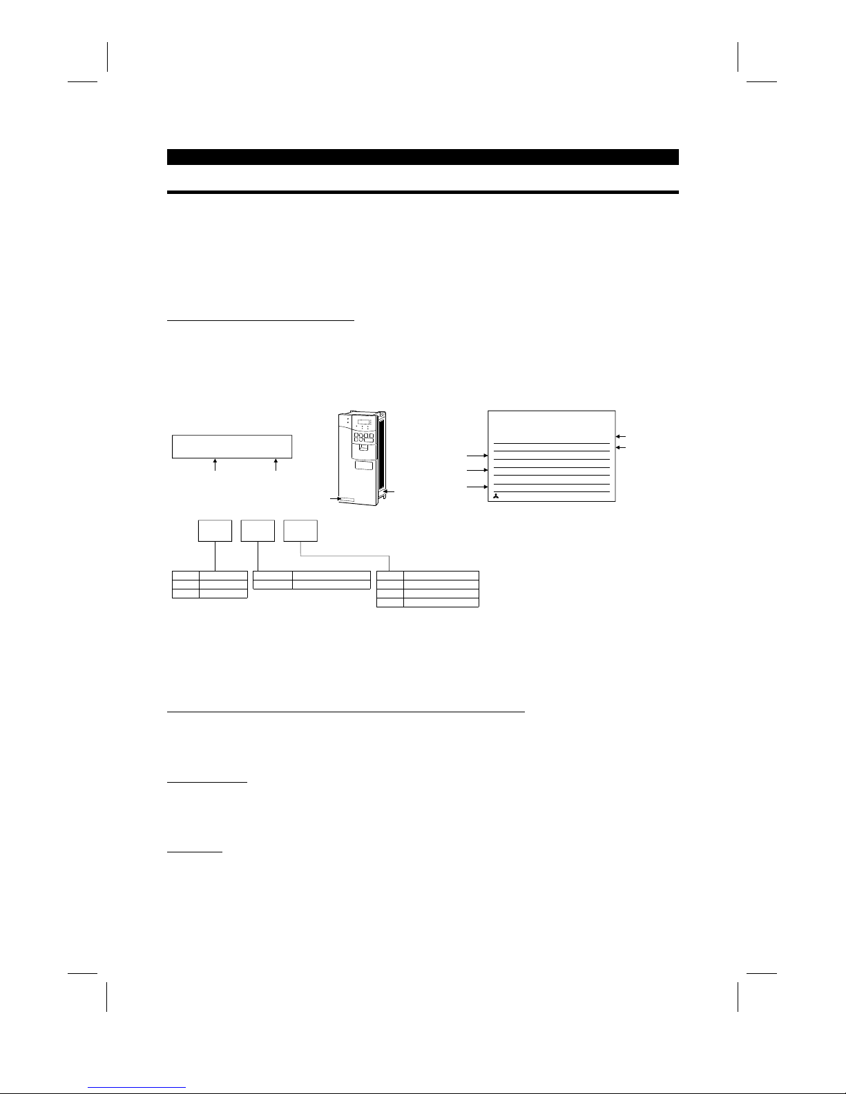
(1)
Unpacking and product check
Unpack the inverter and check the capacity plate on the front cover and the rating plate on the inverter side
face to ensure that the product agrees with your order and the inverter is intact.
1) Inverter type
FR-A520-0.4K/
MITSUBISHI
MODEL
FR-A520-0.4K
INVERTER
POWER
INPUT
OUTPUT
SERIAL
MITSUBISHI ELECTRIC CORPORATION
0.4kW
XXXXX
MADE IN JAPAN
XXXXX
Capacity plate
Inverter type Serial number
Capacity plate
Rating plate
Rating plate
Input rating
Output rating
Serial number
Inverter type
FR- A520 - 0.4K -
Symbol Voltage Class
A520
A540
200V class
400V class
Symbol Applicable Motor Capacity
0.4K to 55K Indicates capacity in "kW".
Symbol Specifications
NoneNAJapanese specifications
U.S. specifications
EC European specifications
Applicable moto
r
capacity
2) Accessory
Instruction manual
If you have found any discrepancy, damage, etc., please contact your sales representative.
(2)
Preparations of instruments and parts required for operation
Instruments and parts to be prepared depend on how the inverter is operated. Prepare equipment and parts
as necessary. (Refer to page 45.)
(3)
Installation
To operate the inverter with high performance f or a long time, install the inverter in a proper place, in the
correct direction, and with proper clearances. (Refer to page 7.)
(4)
Wiring
Connect the power supply, motor and operation signals (control signals) to the terminal block. Note that
incorrect connection may damage the inverter and peripheral devices. (See page 12.)
Artisan Technology Group - Quality Instrumentation ... Guaranteed | (888) 88-SOURCE | www.artisantg.com
1.2 Basic Configuration
OUTLINE
2
1.2 Basic Configuration
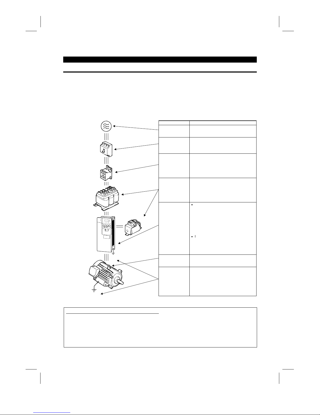
1.2.1 Basic configuration
The following devices are required to operate the inverter. Pr oper peripheral devices must be selected and
correct connections made to ensure proper operation. Inc orrect system configuration and connections can
cause the inverter to operate improperly, its life to be reduced considerably, and in the worst case, the
inverter to be damaged.
Please handle the inverter properly in accordance with the information in each section as well as the
precautions and instructions of this manual. (For connections of the peripheral devices, refer to the
corresponding manuals.)
Name Description
Power supply
Use the power supply within the perm is si ble
power supply specifications of the in verter.
(Refer to page 39.)
Earth leakage
circuit breaker
(ELB) or no-fuse
breaker (NFB)
The breaker should be selected with care
since a large inrush current flows in the
inverter at power on. (Refer to page 39.)
Magnetic
contactor
The magnetic contactor need not be
provided. When installed, do not us e it to
start or stop the inverter. It might reduce the
inverter life.
(Refer to page 39.)
Reactors
The reactors must be used when t he power
factor is to be improved or the inverter is
installed near a large power supply system
(1000KVA or more and wiring distance
within 10m (32.81 feet)). Make selection
carefully.
Inverter
z
The inverter life is influenced by ambient
temperature. The ambient temperature
should be as low as possible within the
permissible range.
This must be noted especiall y when the
inverter is installed in an enclosure.
(Refer to page 7.)
z
Incorrect wiring might lead to inverter
damage. The control signal lines should
be kept away from the main circuit to
protect them from nois e. (Refer to page
9.)
Devices
connected to the
output
Do not connect a power capacitor, surge
suppressor or radio noise filter to the output
side.
(MC)
Ground
DC reactor
(FR-BEL)
Ground
(NFB)
or
(ELB)
AC reactor
(FR-BAL)
Ground
To prevent an electric shock, always ground
the motor and inverter.
Japanese Harmonic Suppression Guideline
The "harmonic suppression guideline for household appliances and general-purpose products" was issued
by the Ministry of International Trade and Industry in September, 1994. This
g
uideline applies to the
FR-A520-0.4K to 3.7K. By connection of the power factor im provin
g
reactor (FR-BEL or FR-BAL), this
product conforms to the "harm onic suppr ession technique f or transistor ized inverters (input c urrent 20A or
less)" set forth by the Japan Electrical Manufactures' Association.
Artisan Technology Group - Quality Instrumentation ... Guaranteed | (888) 88-SOURCE | www.artisantg.com
1.3 Structure
OUTLINE
3
1.3 Structure
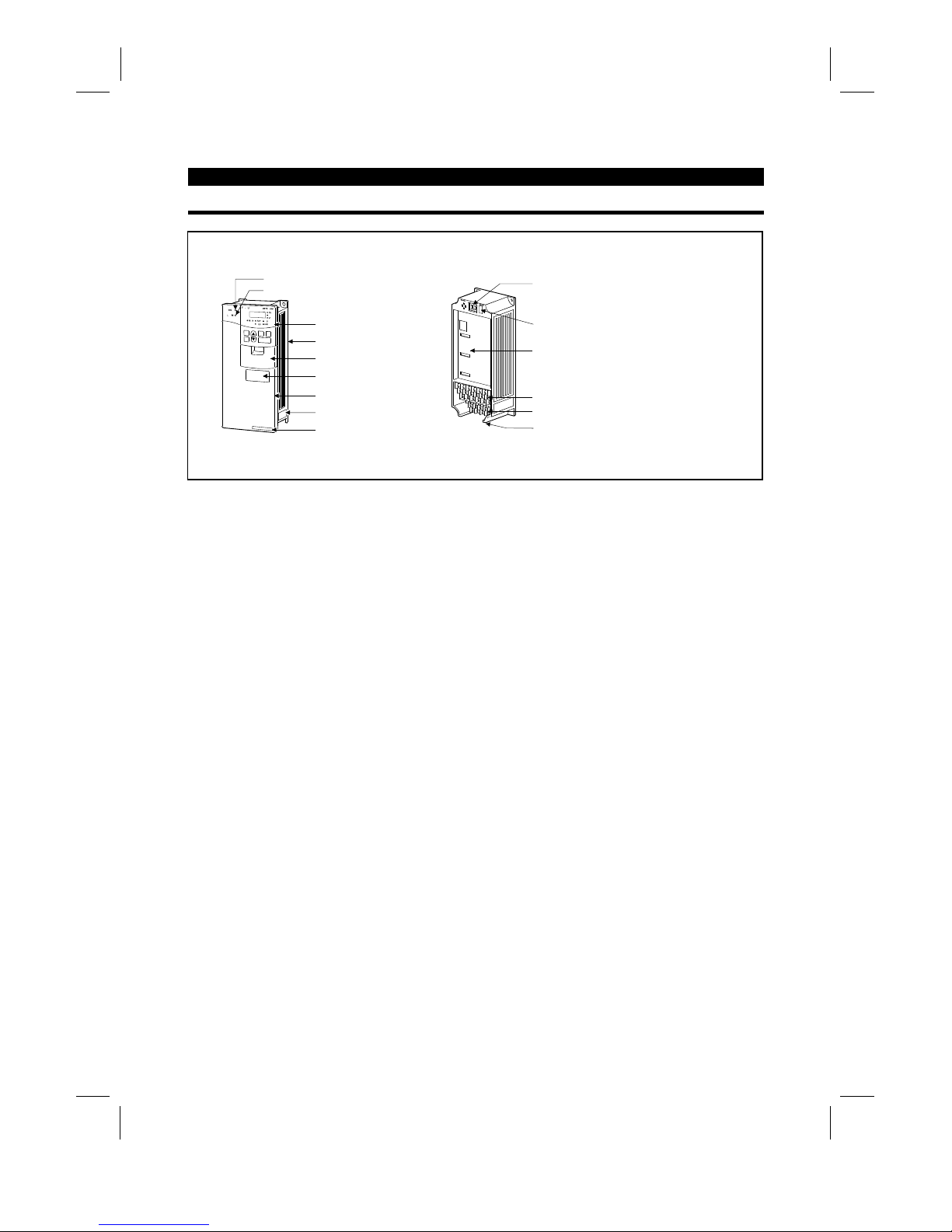
1.3.1 Appearance and structure
(1) Front view (2) Without front cover
POWER lamp
ALARM lamp
Operation panel (FR-DU04)
Brake resistor* (Fitted to the back)
Accessory cover
Wiring port cover for option
Front cover
Rating plate
Capacity plate
Wiring cover
PU connector
(Provided with modular jack type relay connector)
(For use of RS-485 cable)
Modular jack type relay connector compartment
Inboard option mounting position
Control circuit terminal block
Main circuit terminal block
*7.5K or less inverters are equipped with an inboard brake resistor.
Note: The "EC" version of the FR-A500 uses pheonix type connectors f or the control circuit terminal
block.
Artisan Technology Group - Quality Instrumentation ... Guaranteed | (888) 88-SOURCE | www.artisantg.com
OUTLINE
4
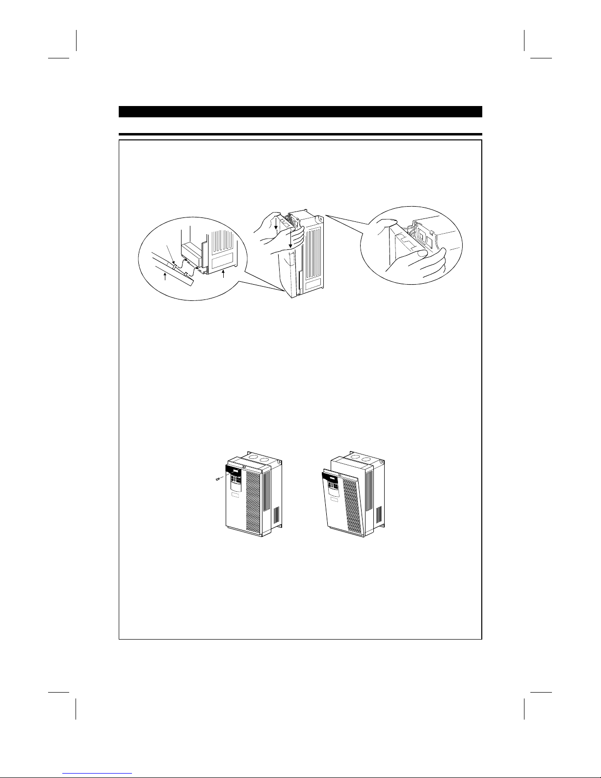
1.3.2 Removal and reinstallation of the front cover
FR-A520-0.4K to 11K, FR-A540-0.4K to 7.5K
•
Removal
1) Hold both sides of the front cover top and push the front cover down.
2) Hold down the front cover and pull it toward you to remove.
(The front cover may be removed with the PU (FR-DU04/FR-PU04) on.)
Front cover
Inverter
Catch
•
Reinstallation
1) Insert the catches at the bottom of the front cover into the sockets of the inverter.
2) Using the catches as supports, securely press the front cover against the inverter.
Note: When the operation panel is mounted and the front c over is removed, remove the operation
panel before reinstalling the front cover.
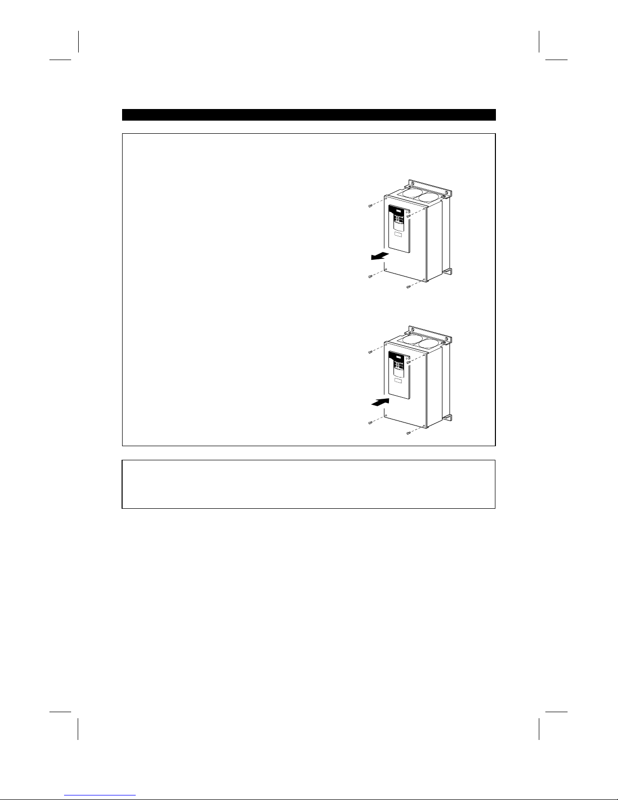
FR-A520-15K to 22K, FR-A540-11K to 22K
•
Removal
1) Remove the installation screw at top of the front cover.
2) Hold both ends of the front cover top.
3) Pull the front cover toward you to remove.
(The front cover may be removed with the PU (FR-DU04/FR-PU04) on.)
•
Reinstallation
1) Insert the catches at the front cover bottom into the sockets of the inverter.
2) Using the catches as supports, securely press the front cover against the inverter.
3) Fix the front cover with the top screw.
Note: When the operation panel is m ounted on the front cover removed, rem ove the operation panel
before reinstalling the front cover.
Artisan Technology Group - Quality Instrumentation ... Guaranteed | (888) 88-SOURCE | www.artisantg.com
OUTLINE
5
FR-A520-30K to 55K, FR-A540-30K to 55K
•
Removal
1) Remove the front cover mounting screws.
•
Reinstallation
1) Fix the front cover with the mounting screws.
Note: 1. Make sure that the front cover has been reinstalled securely.
2. The sam e ser ial number is printed on the capacity plate of the front c over and the r ating plate of
the inverter. Before reinstalling the front cover, c heck the serial number to ensure that the cover
removed is reinstalled to the inverter from where it was removed.
Artisan Technology Group - Quality Instrumentation ... Guaranteed | (888) 88-SOURCE | www.artisantg.com
OUTLINE
6
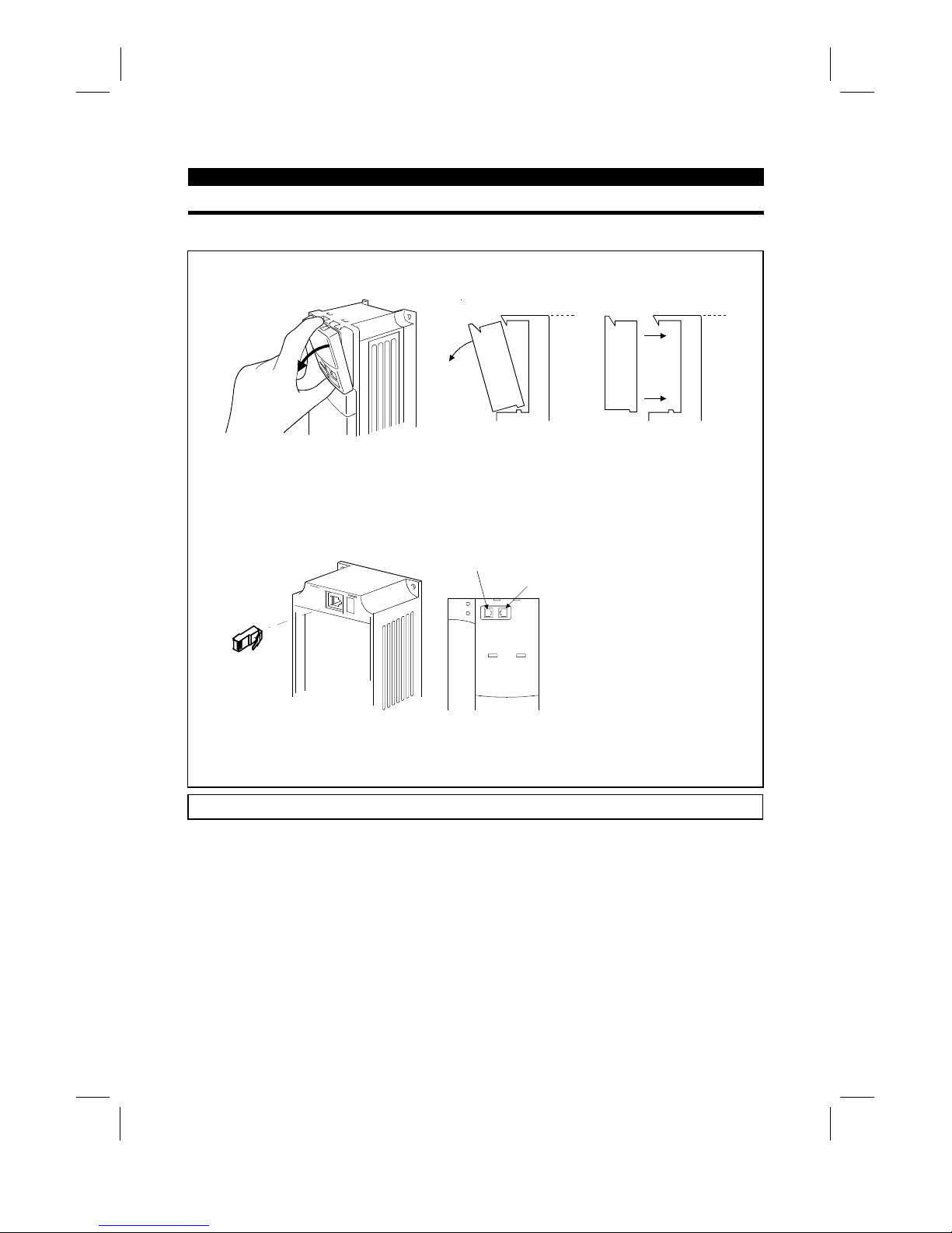
1.3.3 Removal and reinstallation of the operation panel
To ensure safety, remove and reinstall the operation panel after switching power off.
•
Removal
Hold down the top button of the operation panel and pull the operation panel toward you to remove.
Removal
Reinstallation
To reinstall, insert straight and mount securely.
•
Reinstallation using the connection cable
1) Remove the operation panel.
2) Disconnect the modular jack type relay connector. (Place the disconnec ted m odular j ack type relay
connector in the modular jack type relay connector compartment.)
Modular jack type relay connector compartment
Modular jack type relay connector
3) Securely plug one end of the connection cable into the PU connector (m odular jack type relay
connector) of the inverter and the other end into the operation panel.
Note: Install the operation panel only when the front cover is on the inverter.
Artisan Technology Group - Quality Instrumentation ... Guaranteed | (888) 88-SOURCE | www.artisantg.com

2
CHAPTER 2
INSTALLATION AND WIRING
This chapter gives information on the basic "installation and
wiring" of this product.
Always read the instructions in this chapter before using the
equipment.
2.1 Installation................................................................ 7
2.2 Wiring ...................................................................... 9
2.3 Other wiring .............................................................29
CHAPTER 1 OUTLINE
CHAPTER 2 INSTALLATION AND WIRING
CHAPTER 3 OPERATION
CHAPTER 4 PARAMETERS
CHAPTER 5 PROTECTIVE FUNCTIONS
CHAPTER 6 SPECIFICATIONS
CHAPTER 7 OPTIONS
APPENDICES
Artisan Technology Group - Quality Instrumentation ... Guaranteed | (888) 88-SOURCE | www.artisantg.com
2.1 Installation
INSTALLATION AND WIRING
7
2 INSTALLATION AND WIRING
2.1 Installation
2.1.1 Instructions for installation
1) Handle the unit carefully.
The inverter uses plastic parts. Handle it gently to protect it from damage. Also, hold the unit with even
strength and do not apply too much strength to the front cover alone.
2) Install the inverter in a place where it is immune to vibration. (5.9 m/s
2
{0.6G} or less)
Also note the cart, press, etc.
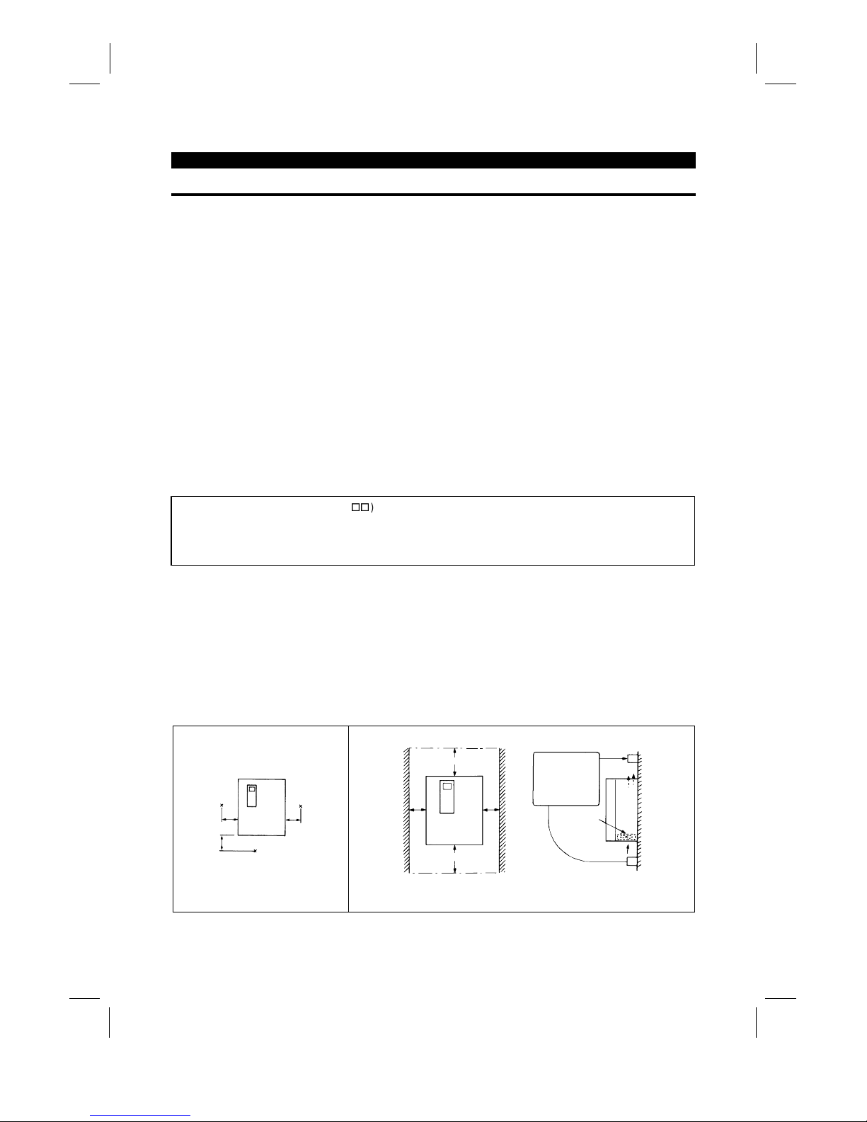
3) Note on ambient temperature
The inverter life is under great influence of ambient temperature. In the place of installation, ambient
temperature must be within the permissible range (depending upon the operation mode and conditions
(see ambient temperature specifications on page 190). Check that the ambient temperature is within that
range in the positions shown in figure 3).
4) Install the inverter on a non-combustible surface.
The inverter will be very hot (maximum about 150°C). Install it on a non-combustible surface (e.g. metal).
Also leave sufficient clearances around the inverter.
5) Avoid high temperature and high humidity.
Avoid places where the inverter is subjected to direct sunlight, high temperature and high humidity.
6) The amount of heat generated in an enclosure can be reduced c onsiderably by placing the heat sink
outside the enclosure.
Note: 1. Use the option (FR-A5CN
) for installation. The mounting area should be cut to the panel
cutting dimensions.
2. The cooling section outside the enclosure has the cooling fan. Do not use the inverter in any
environment where it is exposed to waterdrops, oil mist, dust, etc.
7) Avoid places where the inverter is exposed to oil mist, flammable gases, fluff, dust, dirt etc.
Install the inverter in a clean place or inside a "totally enclosed" panel which does not accept any
suspended matter.
8) Note the cooling method when the inverter is installed in an enclosure.
When two or more inverters are installed or a ventilation fan is mounted in an enclosure, the inverters and
ventilation fan must be installed in proper positions with extreme care taken to keep the ambient
temperatures of the inverters below the permissible value. If they are installed in improper positions, the
ambient temperatures of the inverters will rise and ventilation effect will be reduced.
9) Install the inverter securely with screws or bolts in the vertical direction.
3) Note on ambient temperature
Measurement
position
Measurement
position
5cm
(1.97 inches)
5cm
(1.97 inches)
5cm
(1.97 inches)
4) Clearances around the inverter
10cm (3.94 inches)
5cm (1.97 inches)
or more *
*: 1cm (0.39 inches) or more for model 3.7K or less
Leave sufficient
clearances above
and under the
inverter to ensure
adequate ventilation.
Cooling fan built
in the inverter
Cooling air
5cm (1.97 inches)
or more *
or more
10cm (3.94 inches)
or more
Artisan Technology Group - Quality Instrumentation ... Guaranteed | (888) 88-SOURCE | www.artisantg.com

INSTALLATION AND WIRING
8
8) For installation in an enclosure
Ventilation fan
(Correct example)
Position of Ventilat ion Fan
Inveter Inveter
Inveter
(Correct example) (Incorrect example)
Built-in cooling fan
Inveter
Inveter
Inveter
Accommodation of two or more inv erters
(Incorrect example)
9) Vertical mounting
(1)
Wiring cover and handling (22K or less
)
1) When cable conduits are not connected
Cut the protective bushes of the wiring cover with nippers or a cutter before running the cables.
Wiring cover
Protective bush
WARNING
Do not remove the protective bushes. Otherwise, the cable sheathes may be scratched by the wiring cover
edges, resulting in a short circuit or ground fault.
2) When cable conduits are connected
Remove the corresponding protective bushes and connect the cable conduits.
Artisan Technology Group - Quality Instrumentation ... Guaranteed | (888) 88-SOURCE | www.artisantg.com
2.2 Wiring
INSTALLATION AND WIRING
9
2.2 Wiring
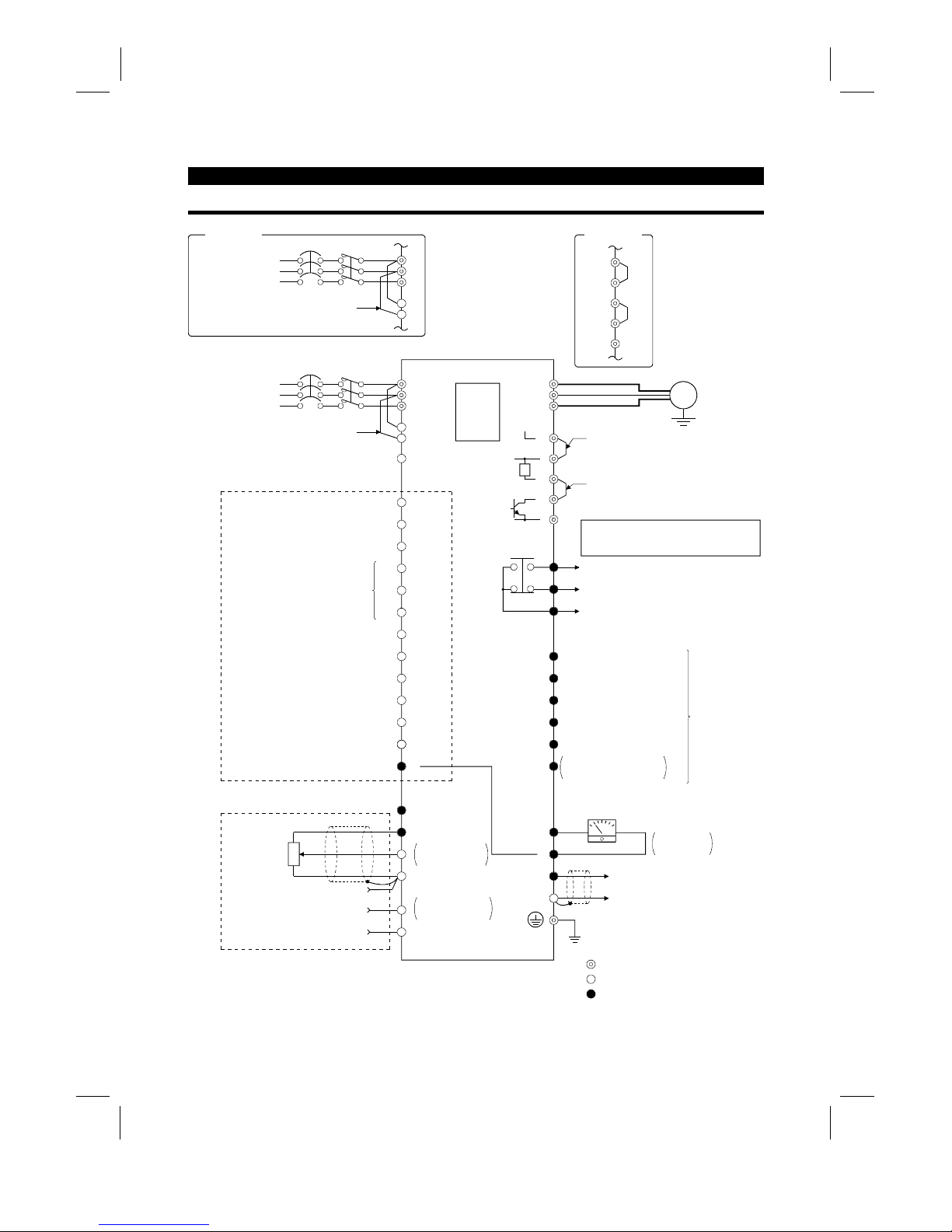
2.2.1 Terminal connection diagram
NFB
R
S
T
R1
S1
PC
STF
STR
STOP
RH
RM
RL
JOG
RT
MRS
RES
AU
CS
SD
10E(+10V)
10(+5V)
2
5
2
3
1
1
4 (4 to 20mADC)
Frequency setting
potentiometer
1/2W1k
Ω
RUN
SU
IPF
OL
FU
SE
FM
SD
IM
A
B
C
U
V
W
P1
P
PX
PR
N
+−
(
−
)
(
+
)
AM
5
R
Ground
Main circuit terminal
Control circuit input terminal
Control circuit output terminal
3-phase AC power supply
Jumper
24VDC power output and external transistor common
(Contact input common for source logic)
Forward rotation start
Reverse rotation start
Start self-holding selection
High
Middle
Low
Jog mode
Second acceleration/deceleration time selection
Output stop
Reset
Current input selection
Selection of automatic restart
after instantaneous power failure
(Contact input common for sink logic)
Control input signals (no voltage input allowed)
Frequency setting signals (analog)
Common
Auxiliary input
Current input
0 to 5VDC
0 to 10VDC
Selected
(Analog common)
0 to ± 5VDC
0 to ±10VDC
Selected
PU
connector
(Note)
(Note)
Motor
Ground
Jumper
Remove this jumper when using FR-BEL.
Jumper
Remove this jumper when using FR-ABR.
Note: Terminals PR, PX are provided for
FR-A520-0.4K to 7.5K.
FR-A540-0.4K to 7.5K
Alarm detection
Running
Up to frequency
Instantaneous power failure
Overload
Frequency detection
Open collector output common
Common to sink and source
Open collector
outputs
Meter
(e.g. frequency meter)
Moving-coil type
1mA full-scale
Analog signal output
(0 to 10VDC)
Multi-speed selection
(RS-485)
NFB
L
1
L
2
L
3
L
11
L
21
3-phase AC power supply
Jumper
EC version
P1
+
PX
PR
–
EC version
Artisan Technology Group - Quality Instrumentation ... Guaranteed | (888) 88-SOURCE | www.artisantg.com
INSTALLATION AND WIRING
10
(1)
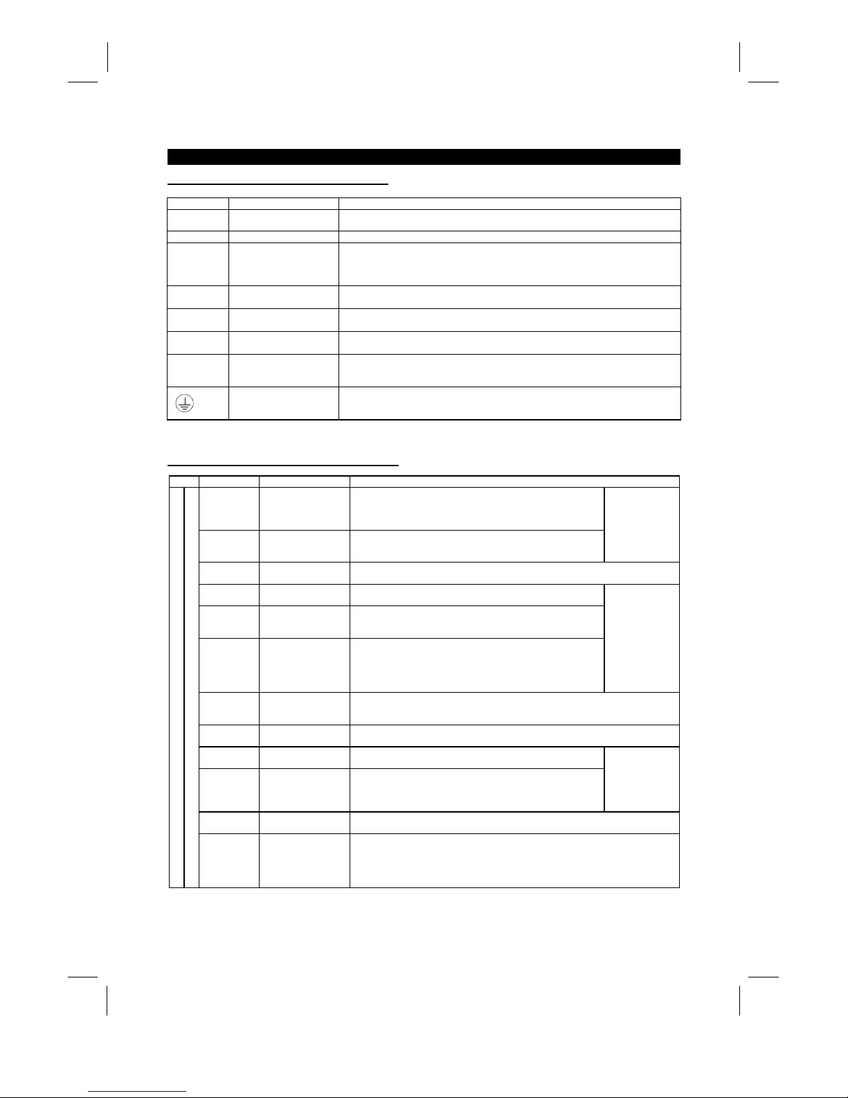
Description of main circuit terminals
Symbol Terminal Name Description
R, S, T
〈
L
1
, L2, L
3
〉
AC power input
Connect to the commerci al power supply. Keep these t erminals unconnected when
using the high power factor converter (FR-HC).
U, V, W Inverter output Connect a three-phase squirrel-cage motor.
R1, S1
〈
L
11
, L
21
〉
Power supply for control
circuit
Connected to the AC power supply terminals R and S 〈L
1
and L
2
〉
. To retain the alarm
display and alarm output or when using the high power factor converter (FR-HC),
remove the jumpers from terminals R-R1 and S-S1 〈L
1
-
L11 and L
2
-
L
21
〉
and apply
external power to these terminals.
P, PR
〈+
, PR
〉
Brake resistor connection
Disconnect the jumper from terminals PR-PX and connect the optional brak e resistor
(FR-ABR) across terminal s P-PR.
P, N
〈+, −〉
Brake unit connection
Connect the optional FR-BU brake unit, power return convert er (FR-RC) or high power
factor converter (FR-HC).
P, P1
〈+
, P1
〉
Power factor improving
DC reactor connection
Disconnect the jumper from terminals P-P1
〈+
-P1〉 and connect the optional power
factor improving reactor (FR-BEL).
PR, PX
Built-in brake circuit
connection
When the jumper is c onnected across terminals PX-PR (factory setting),
the built-in brake circuit is val i d.
(Provided for 7.5K or less.)
Ground For grounding the inverter chassis. Must be earthed.
Note: 〈 〉 Terminal names in parentheses are those of the EC version.
(2)
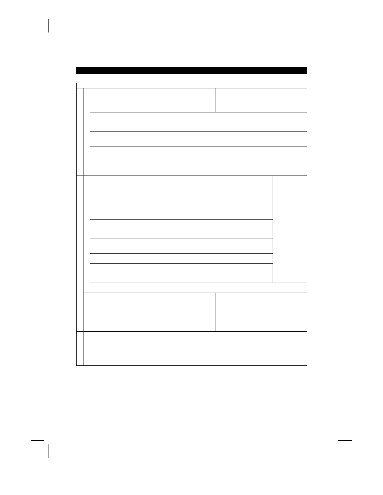
Description of control circuit terminals
Type Symbol Terminal Name Description
STF Forward rotation start
Turn on the STF signal to start forward rotation and t urn i t off to
stop. Acts as a programmed operation start signal in the
programmed operation mode. (Turn on to s tart and turn off to
stop.)
STR Reverse rotation start
Turn on the STR signal to start reverse rot at i on and turn it off to
stop.
When the STF
and STR signals
are turned on
simultaneously,
the stop
command is
given.
STOP
Start self-holding
selection
Turn on the STOP signal to select t he self-holding of the start signal.
RH•RM•RL Multi-speed selection
Use the RH, RM and RL signals as appropriate to select multiple
speeds.
JOG JOG mode selecti on
Turn on the JOG signal to select jog operati on (factory setting).
Jog operation can be performed with the start signal (STF or
STR).
RT
Second acceleration/
deceleration time
selection
Turn on the RT signal to select the sec ond acceleration/
deceleration time. When the second functions such as "second
torque boost" and "second V/F (base frequency)" functions have
been set, these functions c an al so be selected by turning on the
RT signal.
Input terminal
function selection
(Pr. 180 to
Pr. 186) change
terminal
functions.
MRS Output stop
Turn on the MRS signal (20ms or longer) to stop t he i nverter output.
Used to shut off the inverter output to bring the motor to a stop by the magnetic
brake.
RES Reset
Used to reset the protective circuit activated. Turn on the RES signal for more than
0.1 second, then turn it off.
AU
Current input
selection
Only when the AU signal is turned on, the inverter can be
operated with the 4-20mADC frequency setting signal.
CS
Automatic restart after
instantaneous power
failure selection
With the CS signal on, restart can be made automatically when
the power is restored after an instantaneous power failure. Note
that this operation requires restart parameters to be set. When
the inverter is shipped from t he factory, it is set to disallow restart.
In
put terminal
function selection
(Pr. 180 to
Pr. 186) change
terminal
functions.
SD
Contact input
common (sink)
Common to the contact i nput terminals and terminal FM. Common output term i nal f or
24VDC 0.1A power (PC terminal).
Input signals
Contacts, e.g. start (S TF), stop (STOP) etc.
PC
24VDC power and
external transistor
common
Contact input
common (source)
When transistor output (open collector output), such as a programmable controller, is
connected, connect the external power supply common for transistor output to this
terminal to prevent a fault caus ed by l eakage current. This terminal can be used as a
24VDC, 0.1A power output. When source logic has been selected, this terminal
serves as a contact input common.
Artisan Technology Group - Quality Instrumentation ... Guaranteed | (888) 88-SOURCE | www.artisantg.com
INSTALLATION AND WIRING
11
Type Symbol Terminal Name Description
10E
10VDC, permissible load
current 10mA
10
Frequency setting
power supply
5VDC, permissible load current
10mA
When the frequency setti ng potentiometer is
connected in the factory-set s tate, connect it to
terminal 10.
When it is connect ed t o terminal 10E, change the
input specifications of terminal 2.
2
Frequency setting
(voltage)
By entering 0 to 5VDC (0 to 10VDC), the maxim um output frequency is reached at 5V
(or 10V) and I/O are proportional. Switch between input 0 to 5V DC (f actory setting)
and 0 to 10VDC from the operation panel. Input resistance 10kΩ. Maximum
permissible voltage 20V.
4
Frequency setting
(current)
By entering 4 to 20mADC, the maxim um output frequency is reached at 20mA and
I/O are proportional. This input signal i s valid only when the AU signal is on. Input
resistance 250Ω. Maximum permissible current 30mA.
1
Auxiliary frequency
setting
By entering 0 to ±5VDC 0 to ±10VDC, this signal is added to the frequency setting
signal of terminal 2 or 4. Switch between input 0 to ±5VDC and 0 to ±10VDC (factory
setting) from the operation panel. I nput resistance 10kΩ. Maximum permissible
voltage ±20V.
Input signals
Analog frequency setting
5
Frequency setting
input common
Common to the frequency setting signal (terminal 2, 1 or 4) and analog output
terminal AM. Do not earth.
Contact
A, B, C Alarm output
Change-over contact output indicating t hat the output has been
stopped by the inverter protective function activated.
200VAC 0.3A, 30VDC 0.3A. Alarm: discontinuity across B-C
(continuity across A-C), norm al : continuity across B-C
(discontinuity across A-C).
RUN Inverter running
Switched low when the inverter output frequency is equal to or
higher than the starting frequency (factory set to 0.5Hz, variable).
Switched high during stop or DC dynamic brake operat i on (*2).
Permissible load 24VDC 0.1A.
SU Up to frequency
Switched low when the output frequency has reached within
±
10% of the set frequency (fact o ry setting, variable). Switched
high during acceleration, deceleration or s t op (*2). Permissible
load 24VDC 0.1A.
OL Overload alarm
Switched low when the stall prevention function has c aus ed stall
prevention to be activated. Switched high when stall prevention is
reset (*2). Permissible load 24VDC 0.1A.
IPF
Instantaneous power
failure
Switched low when instantaneous power failure or undervoltage
protection is activated (*2). P ermissible load 24VDC 0.1A.
FU Frequency detection
Switched low when the output frequency has reached or
exceeded the detection frequency set as appropriate. Switched
high when below the detection frequency (*2). Permiss i bl e l oad
24VDC 0.1A
Output terminal
function selection
(Pr. 190 to
Pr. 195) change
terminal
functions.
Open collector
SE
Open collector output
common
Common to the RUN, SU, OL, I P F and F U t erminals.
Pulse
FM For meter
Factory setting of output item:
Frequency
Permissible load current 1mA
1440 pulses/second at 60Hz
Output signals
Analog
AM Analog signal output
One selected from 16
monitoring items, s uch as
output frequency, is output. (*3)
The output signal is
proportional to the magnitude
of each monitoring item.
Factory setting of output item:
Frequency
Output signal 0 to 10VDC
Permissible load current 1mA
Communication
RS-485
PU connector
With the operation panel connector, communication can be made through RS-485.
·
Conforming Standard : EIA Standard RS -485
·
Transmission format : Multi-drop link
·
Communication speed : Maximum 19200 baud rat es
·
Overall length : 500m
*1: Terminals PR and PX are provided for the FR-A520-0.4K to 7.5K, FR-A540-0.4K to 7.5K.
*2: Low indicates that the open collector outputting transistor is on (conducts). High indicates that the
transistor is off (does not conduct).
*3: Not output while the inverter is reset.
Artisan Technology Group - Quality Instrumentation ... Guaranteed | (888) 88-SOURCE | www.artisantg.com
INSTALLATION AND WIRING
12
2.2.2 Wiring of the main circuit
(1)
Wiring instructions
1) Crimping terminals with insulation sleeves are recommended for use with the power and motor cables.
2) Cut the protective bushes of the wiring cover when running the cables. (22K or less)
3) Power must not be applied to the output terminals (U, V, W) of the inverter . Otherwise the inverter will be
damaged.
4) After wiring, wire off-cuts must not be left in the inverter.
Wire off-cuts can cause an alarm, failure or malfunction. Always keep the inverter clean.
When drilling mounting holes in a control box etc., exercise care to prevent chips and other foreign matter
from entering the inverter.
5) Use cables of the recommended size for wiring to make the voltage drop 2% or less.
If the wiring distance is long between the inverter and motor, a main circuit cable voltage drop will cause
the motor torque to decrease especially at the output of a low frequency.
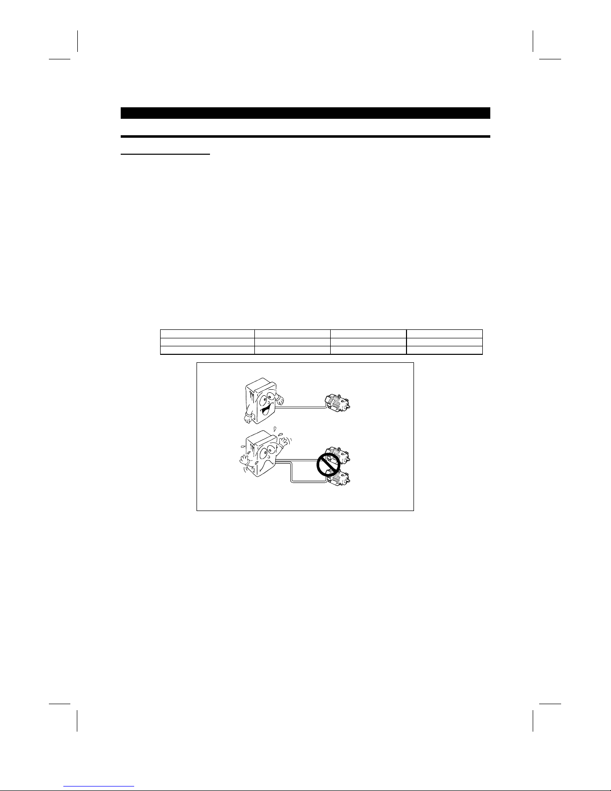
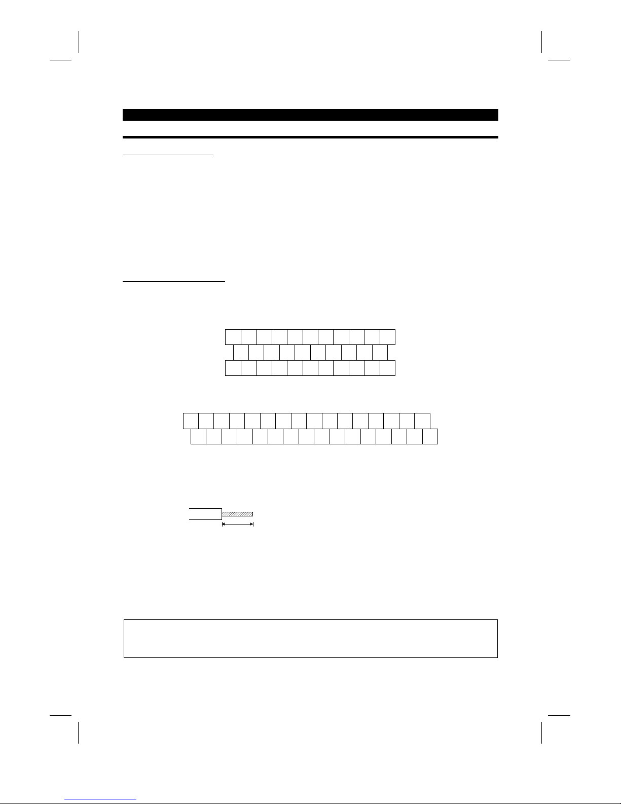
6) The overall wiring length should be 500m (1640.40feet) maximum.
Especially for long distance wiring, the overcurrent protection may be misactivated or the devices connected to the
output side may misoperate or become faulty under the influence of a charging current due to the stray capacitance
of the wiring. Therefore, the maximum overall wiring length should be as indicated in the following table. (When two
or more motors are connected to the inverter, the total wiring length should be within the indicated value.)
Inverter Capacity 0.4K 0.75K 1.5K or more
Non-low acoustic noise mode 300m (984.24 feet) 500m (1640.40 feet) 500m (1640.40 feet)
Low acoustic noise mode 200m (656.16 feet) 300m (984.24 feet) 500m (1640.40 feet)
Overall wiring length (1.5K or more)
300m (984.24 feet) + 300m (984.24 feet) = 600m (1968.48 feet)
500m
(1640.40 feet) maximum
300m
(984.24 feet)
300m
(984.24 feet)
7) Connect only the recommended optional brake resistor between the terminals P and PR 〈+ and PR〉.
These terminals must not be shorted.
8) Electromagnetic wave interference
The input/output (main circuit) of the inverter includes harmonic components, which may interfere with the
communication devices (such as AM radios) used near the inverter. In this case, install the FR-BIF optional radio
noise filter (for use in the input side only) or FR-BSF01 or FR-BLF line noise filter to minimize interference.
9) Do not install a power capacitor, surge suppressor or radio noise filter (FR-BIF option) in the output side of the
inverter.
This will cause the inverter to trip or the capacitor and surge suppressor to be damaged. If any of the above devices
are installed, immediately remove them. (If the FR-BIF radio nois e filter is connected, switching power off during
motor operation may result in E.UVT. In this case, connect the radio noise filter in the primary side of the
electromagnetic contactor.)
Artisan Technology Group - Quality Instrumentation ... Guaranteed | (888) 88-SOURCE | www.artisantg.com
INSTALLATION AND WIRING
13
10) When rewiring after operation, m ake sure that the POW ER lam p has gone off, and when more than 10
minutes have elapsed after power-off, chec k with a tester that the voltage is zero. After that, s tart rewiring
work. For some time after power-off, there is a dangerous voltage in the capacitor.
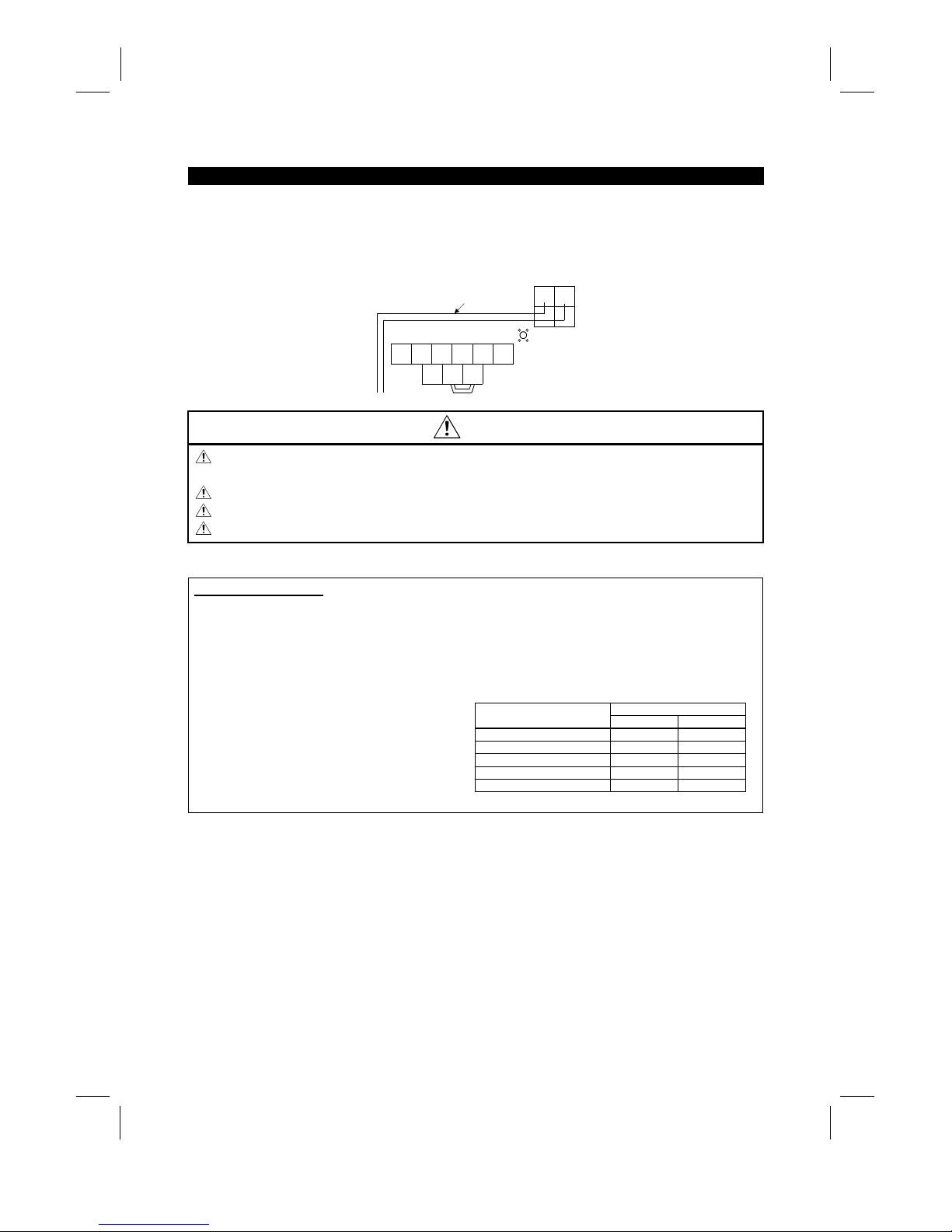
11) Use the space on the left-hand side of the m ain circuit terminal block to run the cable for c onnection of
the control circuit power terminals R1, S1 〈L
11
, L
21
〉
of the FR-A520-11K.
N
UVW
P1
R1 S1
P
Screw size (M5)
Connection cable
Charge lamp
T
〈L3〉
R
〈L1〉S〈L2〉
〈−〉 〈+〉
〈L11〉〈L21〉
CAUTION
Do not use residual current protective device as the only protection against indirect contact.
Protective earth connection essential.
Do not connect more than 2 wires on the protective earth terminal.
Use contactor and no fuse breaker EN/IEC standard compliant.
Use transformer or surge absorber EN/IEC standard compliant.
Notes on Grounding
•
Leakage currents flow in the inverter. To prevent an electric shock, the inverter and motor must be
grounded (200V class...class 3 grounding, grounding resis tance 100Ω maximum), (400V clas s... special
class 3 grounding, grounding resistance 10Ω or less.).
•
Use the dedicated ground terminal to ground the inverter. (Do not us e the screw in the case, chass is,
etc.)
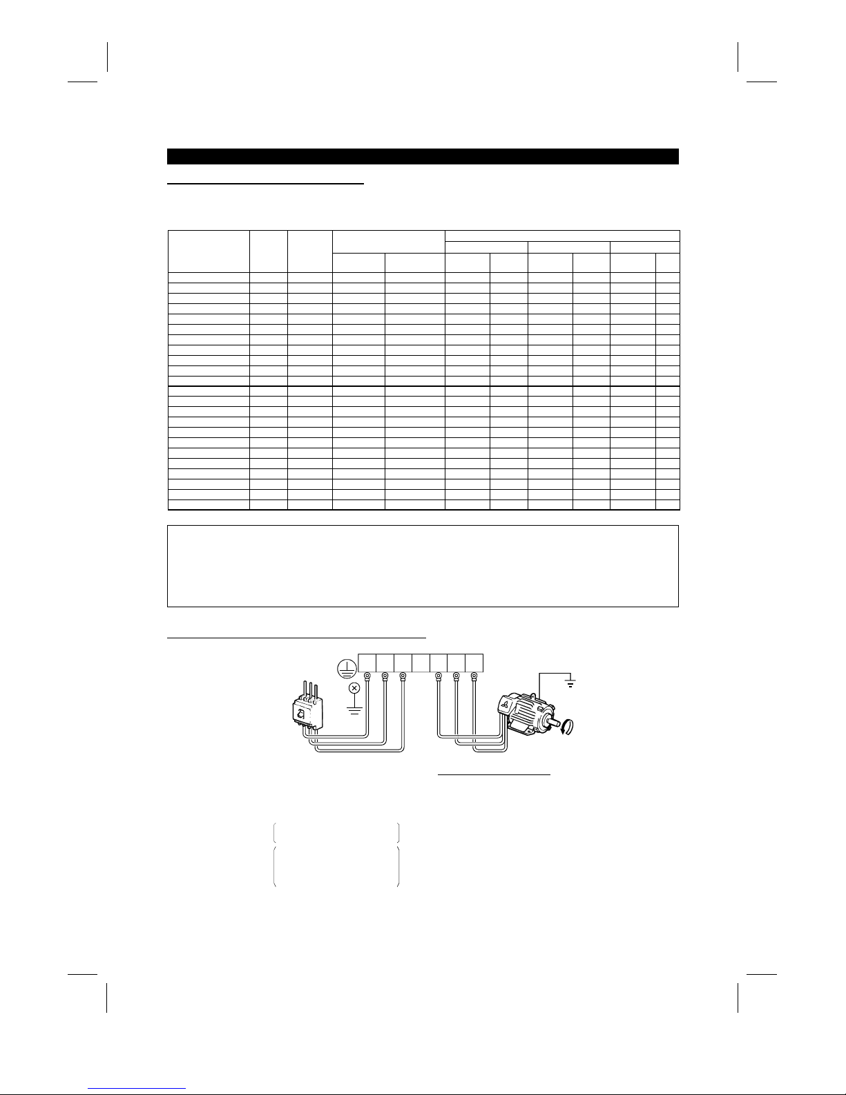
(Unit: mm2)
Ground Cable Gauge
Motor Capacity
200V class 400V class
3.7kW (5HP) or less 3.5 2
5.5k, 7.5Kw (7.5HP, 10HP) 5.5 3.5
11 to 15Kw (15 to 20HP) 14 8
18.5 to 37kW (25 to 50HP) 22 14
45, 55Kw (60, 75HP) 38 22
•
The ground cable should be as thick as possible.
Its gauge should be equal to or larger than those
indicated in the following table. The grounding
point should be as near as possible to the inverter
to minimize the ground cable length.
•
Ground the motor on the inverter side using one
wire of the 4-core cable.
Artisan Technology Group - Quality Instrumentation ... Guaranteed | (888) 88-SOURCE | www.artisantg.com
INSTALLATION AND WIRING
14
(2)
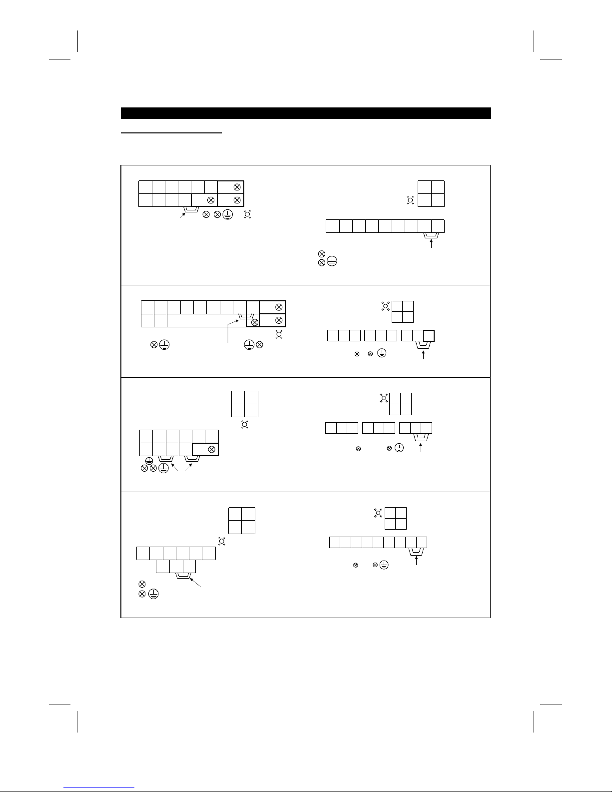
Terminal block layout
In the main circuit of the inverter, the terminals are arranged as shown below:
1) 200V class
FR-A520-0.4K, 0.75K
RR1STUVWPR
S1 N P1 P
(M4)
PX
Jumper
Screw size(M4)
Charge lamp
FR-A520-15K, 18.5K, 22K
RSTUVWNP1P
RS
R1 S1
Screw size
15K(M6)
18.5K,22K(M8)
Jumper
Charge lamp
Screw size (M4)
Screw size (M6)
FR-A520-1.5K, 2.2K, 3.7K
RR1STUVW PR
S1
NP1P
PX
(M4)
Jumper
Screw size (M4)
Charge lamp
FR-A520-30K
RST UVW
R1 S1
N P1 P
RS
Charge lamp
Screw size (M4)
Screw size (M8)
Screw size (M6) Jumper
FR-A520-5.5K, 7.5K
RNSTUVW
P1 P PR PX
R1RS1
S
(M5)
Jumpers
Charge lamp
Screw size
(M4)
Screw size(M5)
FR-A520-37K, 45K
RST UVW
R1 S1
N P1 P
RS
Charge lamp Screw size (M4)
Screw size (M10)
Screw size (M8)
Jumper
FR-A520-11K
RNSTUVW
P1 P
R1RS1
S
Jumper
Screw size (M4)
Charge lamp
Screw size (M5)
S
crew size (M5)
FR-A520-55K
RSTUVW
R1 S1
N P1 P
RS
Charge lamp
Screw size (M4)
Screw size (M12)
Screw size (M8)
Jumper
Artisan Technology Group - Quality Instrumentation ... Guaranteed | (888) 88-SOURCE | www.artisantg.com
INSTALLATION AND WIRING
15
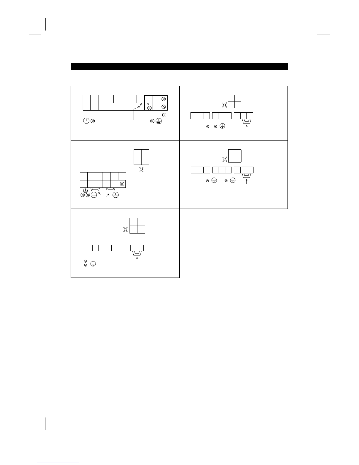
2) 400V class
FR-A540-0.4K, 0.75K, 2.2K, 3.7K
UVW PRP1
PX
(M4)
Screw size (M4)
Jumper
Charge lamp
R
〈L1〉S〈L2〉T〈L3〉
N
〈–〉P〈+〉
R1
〈
L
11
〉S1〈
L
21
〉
FR-A540-30K
UVW P1
Jumper
Screw size (M4)
Screw size (M6)
Screw size (M6)
Charge lamp
S
〈L2〉R〈L1〉T〈L3〉
R
〈L1〉S〈L2〉
R1
〈L11〉S1〈L12〉
N
〈–〉P〈+〉
FR-A540-5.5K, 7.5K
UVW
P1 PR PX
(M5)
Screw size (M4)
Charge lamp
Screw size (M4)
Jumpers
R
〈
L
1
〉S〈
L
2
〉T〈
L
3
〉
N
〈–〉
P
〈+〉
R
〈L1〉S〈L2〉
R1
〈L11〉S1〈L12〉
FR-A540-37K, 45K, 55K
S
〈
L
2
〉R〈
L
1
〉
UVW P1
Jumper
Screw size (M4)
Screw size (M8)
Screw size (M8)
Charge lamp
T
〈
L
3
〉
R
〈L1〉S〈L2〉
R1
〈L11〉S1〈L12〉
N
〈–〉P〈+〉
FR-A540-11K, 15K, 18.5K, 22K
S
〈
L
2
〉
UVW P1
Jumper
Screw size (M4)
Charge lamp
Screw size (M6)
Screw size (M6)
R
〈
L
1
〉T〈
L
3
〉
R
〈L1〉S〈L2〉
R1
〈L11〉S1〈L12〉
N
〈–〉P〈+〉
Note: 〈 〉 Terminal names in parentheses are those of the EC version.
Artisan Technology Group - Quality Instrumentation ... Guaranteed | (888) 88-SOURCE | www.artisantg.com
INSTALLATION AND WIRING
16
(3)
Cables, crimping terminals, etc.
The following table lists the cables and crim ping terminals used with the inputs (R, S, T) 〈L1, L2, L
3
〉
and
outputs (U, V, W) of the inverter and the torques for tightening the screws:
Cables (Note 1)
Crimping Terminals
mm
2
AWG PVC
Applicable Inverter Type
Terminal
Screw
Size
Tightening
Torque
Kgf⋅cm
(N⋅m)
R, S, T
〈
L1, L2, L3
〉
U, V, W
R, S, T
〈
L1, L2, L3
〉
U, V, W
R, S, T
〈
L1, L2, L3
〉
U, V, W
R, S, T
〈
L1, L2, L3
〉
U, V,
W
FR-A520-0.4K to 2.2K M4 15 (1) 2-4 〈2.5-4〉2-4 〈2.5-4
〉
2 2 14 14 2.5 2.5
FR-A520-3.7K M4 15 (1) 5.5-4 〈4-4〉5.5-4 〈2.5-4
〉
3.5 3.5 12 12 4 2.5
FR-A520-5.5K M5 26 (2) 5.5-5 〈6-5〉5.5-5 〈4-5
〉
5.5 5.5 10 10 6 4
FR-A520-7.5K M5 26 (2) 14-5 〈16-5〉8-5 〈6-5
〉
14 8 6 8 16 6
FR-A520-11K M5 26 (2) 14-5 〈16-5〉14-5 〈16-5
〉
14 14 6 6 16 10
FR-A520-15K M6 45 (4) 22-6 〈35-6〉22-6 〈16-6
〉
22 22 4 4 35 16
FR-A520-18.5K M8 80 (7) 38-8 〈35-8〉38-8 〈25-8
〉
38 38 2 2 35 25
FR-A520-22K M8 80 (7) 38-8 〈70-8〉38-8 〈35-8
〉
38 38 2 2 70 35
FR-A520-30K M8 80 (7) 60-8 〈95-8〉60-8 〈30-8
〉
60 60 1/0 1/0 95 50
FR-A520-37K M10 150 (14) 100-10 〈95-8〉100-10 〈70-8〉100 100 4/0 4/0 75 70
FR-A520-45K M10 150 (14) 100-10 100-10 〈95-40〉100 100 4/0 4/0
−−
FR-A520-55K M12 250 (24) 150-12 150-12 〈110-12〉150 150 MCM300 MCM300
−−
FR-A540-0.4K to 3.7K M4 15 (1) 2-4 〈2.5-4〉2-4 〈2.5-4
〉
2 2 14 14 2.5 2.5
FR-540-5.5K M4 15 (1) 5.5-4 〈4-4〉2-4 〈2.5-4
〉
3.5 2 12 14 4 2.5
FR-540-7.5K M4 15 (1) 5.5-4 〈4-4〉5.5-4 〈4-4
〉
3.5 3.5 12 12 4 4
FR-540-11K M6 45 (4) 5.5-6 〈6-6〉5.5-6 〈6-6
〉
5.5 5.5 10 10 6 6
FR-540-15K M6 45 (4) 14-6 〈16-6〉8-6 〈10-6
〉
14 8 6 8 16 10
FR-540-18.5K M6 45 (4) 14-6 〈16-6〉8-6 〈10-6
〉
14 8 6 8 16 10
FR-540-22K M6 45 (4) 22-6 〈25-6〉14-6 〈16-6
〉
22 14 4 6 25 16
FR-540-30K M6 45 (4) 22-6 〈25-6〉22-6 〈25-6
〉
22 22 4 4 25 25
FR-540-37K M8 80 (7) 38-8 〈37-8〉22-8 〈25-8
〉
38 22 2 4 35 25
FR-540-45K M8 80 (7) 38-8 〈50-8〉38-8 〈35-8
〉
38 38 2 2 50 35
FR-540-55K M8 80 (7) 60-8 〈70-8〉60-8 〈50-8
〉
60 60 1/0 1/0 70 50
Note: 1. The cables used should be 75°C (167°F) copper cables.
2. Tighten the terminal screws to the specified torques.
Undertightening can cause a short or misoperation.
Overtightening can cause the screws and unit to be damaged, resulting in a short or
misoperation.
(4)
Connection of the power supply and motor
Ground
Ground
Ground
terminal
Power
supply
UVW
UVW
Motor
No-fuse
breaker
The power supply cables
must be connected to R, S, T
〈
L
1
, L2, L
3
〉
.
If they are connected to U, V,
W, the inverter will be damaged.
Phase sequence need not be
matched.
For use with a single-phase
power supply,the power supply
cables must be connected to
R and S 〈L
1
and L
2
〉
.
Connect the motor to U, V, W.
In the above connection,
turning on the forward rotation
switch (signal) rotates the motor
in the counterclockwise (arrow)
direction when viewed from
the load shaft.
R
〈
L
1
〉S〈
L
2
〉T〈
L
3
〉
R
〈
L
1
〉S〈
L
2
〉T〈
L
3
〉
Artisan Technology Group - Quality Instrumentation ... Guaranteed | (888) 88-SOURCE | www.artisantg.com

INSTALLATION AND WIRING
17
(5)
Connecting the control circuit to a power supply separately from the main circuit
If the magnetic contactor (MC) in the inverter power supply is opened when the protective circuit is oper ated,
the inverter control circuit power is lost and the alarm output signal cannot be k ept on. To keep the alarm
signal on terminals R1 and S1 are available. In this case, c onnec t the power supply terminals R1 and S1 〈L
11
and L
21
〉
of the control circuit to the primary side of the MC.
• Model FR-A520-0.4K to 3.7K, FR-A540-0.4K to 3.7K
<Connection procedure>
R
〈L1〉
S
〈L2〉
T
〈L3〉
R1 〈L11〉
S1 〈L21〉
4) Connect the separate power supply cables for control circuit to the
lower terminals (R1, S1 〈L11, L21〉). (Note 4)
Terminal block for main circuit
1) Loosen the upper screws
2) Remove the lower screws.
3) Remove the jumpers.
• Model FR-A520-5.5K to 55K, FR-A540-5.5K to 55K
<Connection procedure>
M
C
1) Loosen the upper screws.
2) Remove the lower screws.
3) Pull out and remove the jumper.
4) Connect the separate power supply
cables for control circuit to the
upper terminals (R1, S1 〈L11, L21〉). (Note 4)
Power supply terminal
block for control circuit
Main power supply
Power supply terminal
block for control circuit
R
〈
L
1
〉S〈
L
2
〉T〈
L
3
〉
R1
〈
L
11
〉S1〈
L
21
〉
Note: 1. When the main circuit power (R, S, T ) 〈L1 L2, L
3
〉
is on, do not switch off the control power
(terminals R1, S1 〈L
11
, L
21
〉
). Otherwise the inverter may be damaged.
2. W hen using a separate power supply, the jumpers acros s R-R1 and S-S1 〈L
1
-
L
11
and L
2
-
L
21
〉
must be removed. Otherwise the inverter may be damaged.
3. For a diff erent power supply system which takes the power of the control c ircuit from other than
the primary side of the MC, the voltage should be equal to the main circuit voltage.
4. For the FR-A520-5.5K to 55K, FR-A540-5.5K to 55K, the power supply cables must not be
connected to the lower terminals. If connected, the inverter may be damaged.
Artisan Technology Group - Quality Instrumentation ... Guaranteed | (888) 88-SOURCE | www.artisantg.com
INSTALLATION AND WIRING
18
2.2.3 Wiring of the control circuit
(1)
Wiring instructions
1) Terminals SD, SE and 5 are com mon to the I/O signals and isolated from each other . These common
terminals must not be connected to each other or earthed.
2) Use shielded or twisted cables for connection to the control circuit terminals and run them away from the
main and power circuits (including the 200V relay sequence circuit).
3) The frequency input signals to the control circuit are m icro currents . W hen contacts are required, use two
or more parallel micro signal contacts or a twin contact to prevent a contact fault.
4) It is recommended to use the cables of 0.75mm
2
gauge for connection to the control circuit term inals.
If the cable gauge used is 1.25mm
2
or more, the front cover may be lifted when there are many cables
running or the cables are run improperly, resulting in an operation panel or parameter unit contact fault.
(2)
Terminal block layout
•
Japanese and NA version
In the control circuit of the inverter, the terminals are arranged as shown below:
Terminal screw size: M3.5
A
RL
SE RUN SU IPF OL FU SD STF STR JOG CS
RM RH RT AU STOP MRS RES SD FM
B C PC AM 10E 10 2 5 4 1
•
EC version
Terminal screw size: M3.5
A
SE RUN SU LPF OL STOP MRS RES PC STF
B C SD AM 10E 10 2 5 4 1 RL RM RH RT AU
STR JOG CS FM SDFU
<Wiring procedure>
1) For the wiring of the control circuit, strip the sheaths of the cables and use them as they are.
Strip the sheath to the following dimension. A too long stripping dimens ion may cause a short circuit with
the neighboring cable. A too short dimension may cause cable disconnection.
6mm ± 1mm
2) Loosen the terminal screw and insert the cable into the terminal.
3) Tighten the screw to the specified torque.
Undertightening can cause cable disconnection or malfunction. Overtightening can cause a short circuit or
malfunction due to the screw or unit damaged.
Tightening torque: 5 to 6 kgf⋅cm
Note: Wire the stripped cable by twisting it to prevent it from becoming loose. (Do not plate the cable with
solder.)
Note: 1. Use a NFB (No fuse breakers) or fuse on the inverter input (primary) side.
2. Make sure that the control circuit terminal wiring does not touch power circuit terminals (or
screws) or conducting power circuit.
Artisan Technology Group - Quality Instrumentation ... Guaranteed | (888) 88-SOURCE | www.artisantg.com
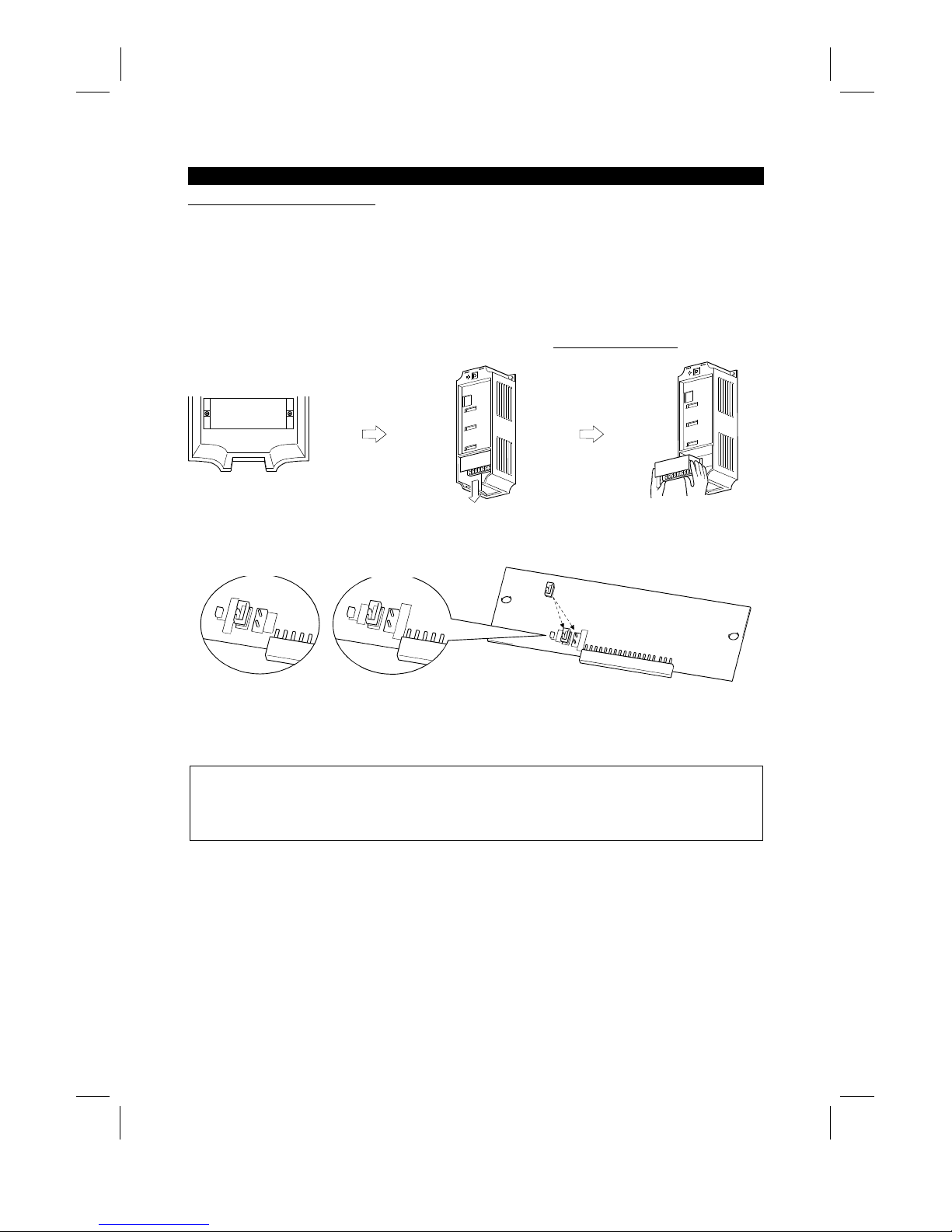
INSTALLATION AND WIRING
19
(3)
Changing the control logic
The input signals are set to sink logic f or the Japanese and NA version, and to source Logic for the EC
version.
To change the control logic, the connector on the back of the control circuit terminal block must be moved to
the other position.
(The output signals may be used in either the sink or source logic independently of the connector position.)
1) Loosen the two mounting screws in both ends of the control c ircuit terminal bloc k. (T he screws cannot be
removed.)
With both hands, pull down the terminal block from the back of the control circuit terminals.
2) Remove the connector from the rear surface of the control c ircuit terminal block and place in required
Logic position (either Sink or Source).
SOURCE
CON3
CON2
SINK
CON1
SINK
CON3
CON2
SOURCE
SINK
CON3
CON2
SOURCE
EC version
NA and Japanese version
3) Using care not to bend the pins of the control circuit c onnector, reinstall the control circuit ter minal block
and fix it with the mounting screws.
Note: 1. Make sure that the control circuit connector is fitted correctly.
2. While power is on, never disconnect the control circuit terminal block.
3. The sink -source logic change-over connec tor mus t be fitted in only one of those positions. If it is
fitted in both positions at the same time, the inverter may be damaged.
Artisan Technology Group - Quality Instrumentation ... Guaranteed | (888) 88-SOURCE | www.artisantg.com
 Loading...