

Mitsubishi F940GOT-WD-E Installation Manual
F940GOT Series(F940GOT-*WD-E)
Installation Manual
JY992D94201B
This manual contains text, diagrams and explanations which will guide the reader in the correct
installation, safe use and operation of the F94*GOT-*WD-E and should be read and understood before
attempting to install or use the unit. Further inf ormation can be found in the associated manuals list below.
Specifications are subject to change without notice
Guidelines for the Safety of the User and Protection of the
F940GOT-*WD-E
This manual has been written to be used by trained and competent personnel. The definition of such a
person or persons is as follows:
a) Any engineer using the product associated with this manual, should be of a competent nature,
trained and qualified to the local and national standards. These engineers should be fully aw are of
all aspects of safety with regards to automated equipment.
b) Any commissioning or service engineer must be of a competent nature, trained and qualified to
the local and national standards.
c) All operators of the completed equipment should be trained to use that product in a safe and
co-ordinated manner in compliance to established safety practices.
The term ‘completed equipment’ refers to a third party constructed device which contains or uses
Note:
the product associated with this manual.
Note’s on the Symbols Used in this Manual
At various times through out this manual certain symbols will be used to highlight points of information
which are intended to ensure the users personal safety and protect the integrity of equipment.
1) Indicates that the identified danger
cause physical and property damage.
WILL
2) Indicates that the identified danger could
damage.
• Under no circumstances will Mitsubishi Electric be liable or responsible for any consequential damage
that may arise as a result of the installation or use of this equipment.
• All examples and diagrams shown in this manual are intended only as an aid to understanding the
text, not to guarantee operation. Mitsubishi Electric will accept no responsibili ty for actual use of the
product based on these illustrative examples.
• Owing to the very great variety in possible application of this equipment, you must satisfy yourself as
to its suitability for your specific application.
POSSIBLY
cause physical and property
Associated Manuals
Manual Name Manual Number Description
GOT-F900 Series
¤
Operation Manual
GOT-F900 Series
¤
Hardware Manual
(connection diagram)
FX-PCS-DU/WIN-E
¢
Operation Manual
SW*D5C-GOTR-PACKE
¢
Operating Manual
F9GT-40UMB
¨
Manual
¤
Indispensable manual
¢
Either manual is necessary.
¨
Refer if necessary, please.
Refer to the manual of the connected programmable controller for details concerning that unit.
JY992D94701
JY992D94801
JY992D68301
-
JY992D74101
This manual contains explanations for the
operation and use of the GOT-F900 series
graphic operation terminals.
This manual contains explanations for the
wiring and installation, etc. of the GOT-F900
series graphic operation terminals.
This manual contains explanations for the
operation of FX-PCS-DU/WIN-E screen design
software.
This manual contains explanations for the
operation of GT-Designer (SW*D5C-GOTRPACKE) screen design software.
This manual contains explanations for
installation and operating procedure of F9GT40UMB data transfer adapter
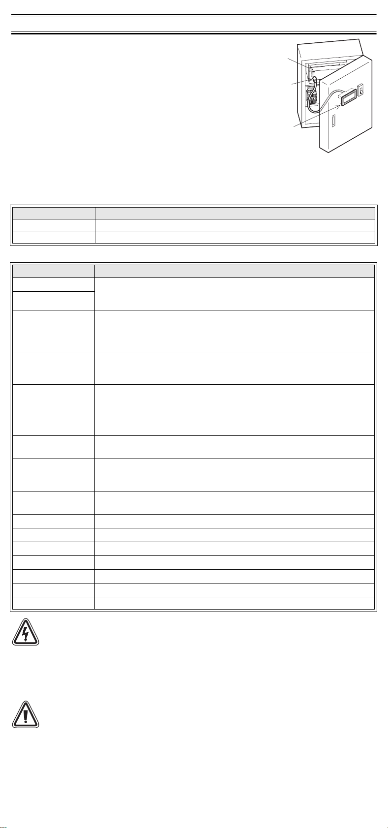
1. Introduction
The F940GOT-*WD-E (hereafter called “GOT” or “F940GOT”) is
to be mounted on the face of a control panel or operations panel,
and connected to the programming port (CPU port) or the
communication port (communication units port) of a PLC.
Various devices can be monitored and PLC data changed
through the screens in the GOT. Several display screens are
built-in to the GOT, and additional personalized screens can be
created by the user.
1) The GOT can connect to MELSEC FX, A, QnA and Q PLCs
as well as a host of third party manufactured units. Further
information can be found in GOT-F900 Series Hardware
Manual.
2) Through the GOT, PLC user programs can be downloaded, uploaded and monitored in programming
software GX-Developer or FX-PCS/WIN-E on a personal computer. Further information can be found
in GOT-F900 Series Operation Manual.
3) Display screens are created using the following software.
Software Name Version
FX-PCS-DU/WIN-E SW0PC-FXDU/WIN-E Version V2.00 or more
GT Designer SW1D5C-GOTR-PACKE Version V 00A or more
1.1 Product Lists
Production Name Description
F940GOT-SWD-E Graphic operation terminal main unit:
F940GOT-LWD-E
FX-50DU-CAB0
FX-50DU-CAB0/EN
FX-50DU-CAB0-**M
FX-40DU-CAB
FX-40DU-CAB0-**M
QC30R2
FX-232CAB-1 Data exchange cable (GOT ↔ Personal computer <9-pin D-sub>)
FX-PCS-DU/WIN-E Screen design software for Windows
GT-Designer Screen design software for Windows (SW*D5C-GOTR-PAKE)
PM-20BL Battery for keeping Alarm history, sampling and current time data
F9GT-40PSC Transparent protection sheet for F940GOT (5 pieces)
F9GT-40LTS Backlight for F940GOT
F9GT-40UMB Data transfer adapter
SWD: 8 colors
LWD: White and b lack
Communication cable (GOT ↔ CPU port in FX
2NC
or FX
series PLC)
The connector on the GOT side is straight.
Cable length is 3m (9' 10").
Communication cable (GOT ↔ CPU port in FX
2NC
or FX
series PLC)
The connector on the GOT side is straight. Cable length is 3m (9' 10").
Communication cable (GOT ↔ CPU port in FX
2NC
or FX
series PLC)
The connector on the GOT side is straight.
** M is cable length. 1M: 1m (3' 3"), 10M: 10m (32' 9"), 20M: 20m (65' 7"),
30M: 30m (98' 5")
Communication cable (GOT ↔ CPU port in FX, FX
The connector on the GOT side is straight. Cable length is 3m (9' 10").
Communication cable (GOT ↔ CPU port in FX, FX
The connector on the GOT side is straight.
** M is cable length. 10M: 10m (32' 9"), 20M: 20m (65' 7"), 30M: 30m (98' 5")
Communication cable (GOT ↔ CPU port in Q series PLC)
The connector on the GOT side is straight. Cable length is 3m (9' 10").
PLC
Program m ing
port
GOT
0
, FX0S, FX1S, FX0N, FX1N, FX2N
0
, FX0S, FX1S, FX0N, FX1N, FX2N
0
, FX0S, FX1S, FX0N, FX1N, FX2N
2C
, A or QnA series PLC)
2C
, A or QnA series PLC)
Caution
During abnormal communication (including cable break) when monitor is executed within the
GOT, communication between the GOT and programmable controller CPU is interrupted and
it is impossible to operate switches or devices in the PLC through the GOT.
Communication and operation resumes when the GOT system is correctly configured.
DO NOT configure emergency stop or safety features to operate through the GOT, and be
sure that there is no adverse consequences in the event of a GOT - PLC communications
malfunction.
Note;
• Do not lay signal cables near high voltage power cables or allow them to share the same
trunking duct.
Otherwise effects of noise or surge induction are likely to take please. Keep a safe
distance of more than 100 mm from these wires.
• Operate touch switches on the display screen by hand.
DO NOT use excessive force, or attempt operate them with hard or pointed objects.
The tip of a screw driver, pen or similar object for example may break the screen.
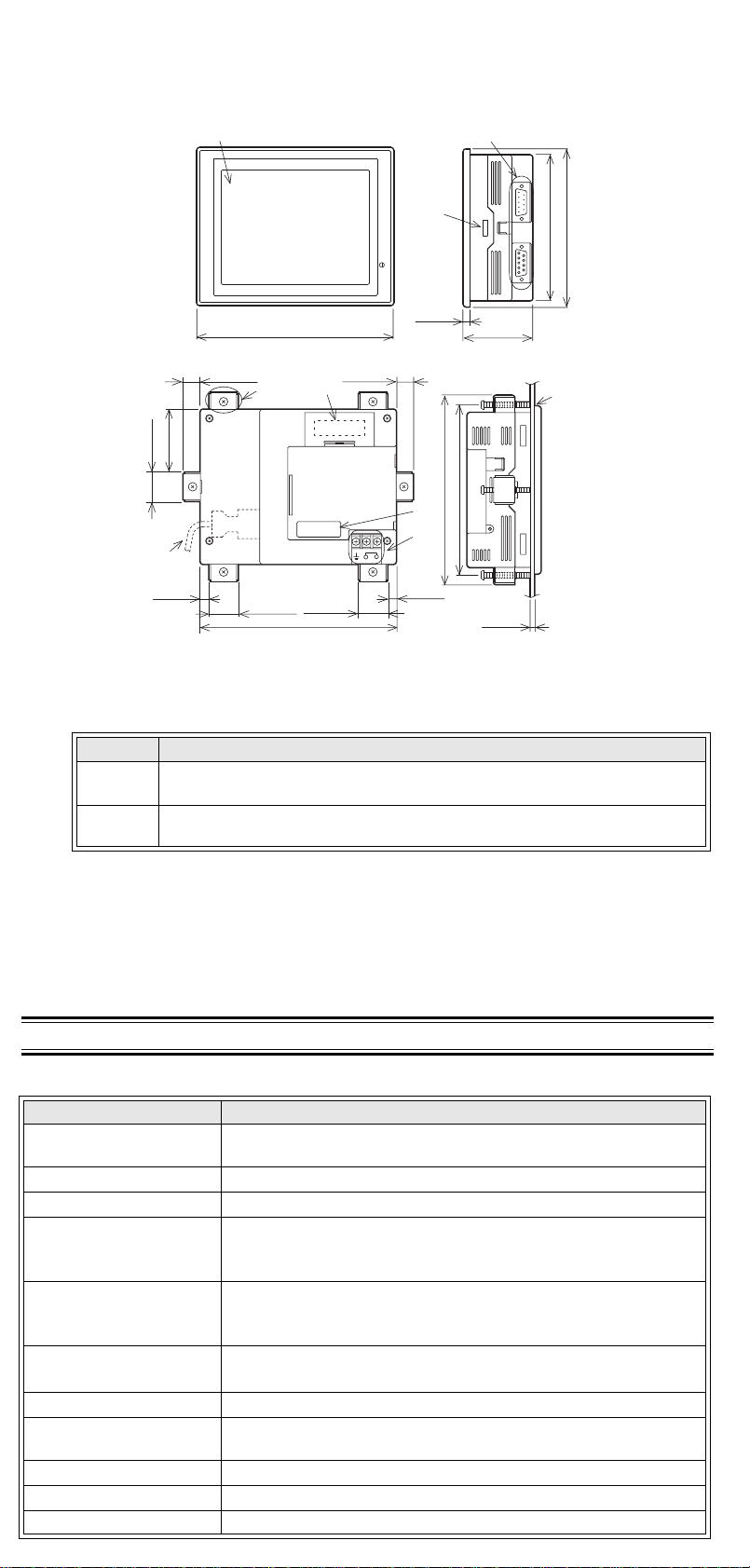
1.2 Dimensions and Each Part N ame
Dimensions: mm (inches) MASS (Weight): 1 kg (2.2 lbs)
Accessory: Mounting brackets, Tightening bolt (M3, 6 bolts),
Packing seal for dust and water resistance
a)
c)
162(6.38")
e)
20(0.79")
10(0.39")
50(1.97")
20(0.79")
h)
8(0.31")
10(0.39")
d)
20(0.79")
152(5.98")
a) Display
b) Mounting bracket hole
c) Comm unication ports
Port Description
RS-422
RS232C
RS-422 Port for connecting PLC (including1:N connection) or communication
(computer link) unit <9-pin D-sub>
RS-232C port for connecting printer, bar-code reader or 1:N connection
<9-pin D-sub>
d) Mounting bracket and tightening bolt
e) PM-20BL battery
f) Expansion interface
g) DC power supply terminal (M3)
h) Communication cable
i) Packing seal
57(2.24")
5(0.20")
RS232C RS422
120(4.72")
130(5.12")
i)
b)
POWER
5(0.20")
f )
140(5.51")
130(5.12")
g)
24V DC
+
-
8(0.31")
2. Specifications
2.1 General Specifications
Item Specifications
Operating Temperature
Storage Temperature -20 ~ 60 °C (-4 ~ 140 °F)
Humidity 35 ~ 85% Relative Humidity, No condensation
Vibration Resistance
- intermittent vibration
Vibration Resistance
- Continuous vibration
Shock Resistance
Noise Immunity 1000 Vp-p, 1micro second, 30 ~ 100 Hz, tested by noise simulator
Dielectric Withstand
Voltage
Insulation Resistance 5 MΩ > at 500 V DC, tested between power terminals and ground
Ground Grounding registance 100 Ω or less. (class D)
Protection IP 65F
0 ~ 50 °C (32 ~ 122 °F)
[With expansion module: 0 ~ 40 °C (32 ~ 104 °F)]
Conforms to IEC 1131-2; 10 ~ 57 Hz: 0.075 mm Half Amplitude
57 ~ 150 Hz: 9.8 m/s
2
Acceleration
Sweep Count for X, Y, Z: 10 times (80 min. in each direction)
Conforms to IEC 1131-2; 10 ~ 57 Hz: 0.035 mm Half Amplitude
2
57 ~ 150 Hz: 4.9 m/s
Acceleration
Sweep Count for X, Y, Z: 10 times (80 min in each direction)
2
Conforms to IEC 1131-2: 147m/s
Acceleration,
3 times in each direction X, Y, and Z
500 V AC > 1 min, tested between power terminals and ground
 Loading...