

Mitsubishi F940GOT-SWD-E, F940GOT-LWD-E Operation Manual
OPERATION MANUAL
F940GOT-SWD-E, F940GOT-LWD-E

Graphic Operation Terminal F940GOT
Foreword
• This manual contains te xt, diag rams and explanations which will guide the reader in the correct installation and operation of the communication facilities of F940GOT.
• Before attempting to install or use the communication facilities of F940GOT this manual
should be read and understood.
• If in doubt at an y stage of the in stall ation o f the c omm unicat ion facilities of F940GOT alw ays
consult a professional electrical engineer wh o is qualified and trained to the local and
national standards which apply to the installation site.
• If in doubt about the operation or use of the communication facilities of F940GOT please
consult the nearest Mitsubisi Electric dis tributor .
• This manual is subject to change without notice.

Graphic Operation Terminal F940GOT
GRAPHIC OPERATION TERMINAL
F940GOT
OPERATION MANUAL
Manual number : JY992D78001
Manual revision : B
Date : August 1999
1

Graphic Operation Terminal F940GOT
2

Graphic Operation Terminal F940GOT
FAX BACK
Mitsubishi has a world wide reputation f or its eff orts in continually developing and pushing back
the frontiers of industrial automation. What is sometimes overlooked by the user is the care
and attention to detail that is taken with the documentation. However,to continue this process
of improvement, the comments of the Mitsubishi users are always welcomed. This page has
been designed for you,the reader,to fil l in y our comments an d fax them back to us. We look forward to hearing from you.
Fax numbers: Your name....................................................
Mitsubishi Electric.... .....................................................................
America (708)298-1834 Your company..............................................
Australia (02)638 7072 .................... .................................................
Germany (0 21 02)4 86-1 12 Your location:................................................
South Africa (0111)444-8304 ........................ .............................................
United Kingdom (01707)278695
Please tick the box of your choice
What condition did the manual arrive in?
Will you be using a f o lder to store the manual?
What do you think to the manual presentation?
Are the explanations understandable?
Which explanation was most difficult to understand:..................................................................
....................................................................................................................................................
Are there any diagrams which are not clear?
If so,which:..................................................................................................................................
What do you think to the manual layout?
If there one thing you would li ke to see improved,what is it?............................. .........................
....................................................................................................................................................
....................................................................................................................................................
Could you find the information you required easily using the index and/or the contents,if possi-
ble please identify your experience:............................................................................................
....................................................................................................................................................
....................................................................................................................................................
....................................................................................................................................................
....................................................................................................................................................
¨
¨
¨
¨
¨
¨
Good
Yes
Tidy
Yes
Yes
Good
¨
Minor damage
¨
No
¨
Un-friendly
¨
Not too bad
¨
No
¨
Not too bad
¨
Unusable
¨
Unusable
¨
Un-helpful
Do you have any comments in general about the Mitsubishi manuals?........................ .. ...........
....................................................................................................................................................
....................................................................................................................................................
....................................................................................................................................................
....................................................................................................................................................
Thank you for taking the time to fill out this questionnaire. We hope you found both the product
and this manual easy to use.
3

Graphic Operation Terminal F940GOT
4

Graphic Operation Terminal F940GOT
Guidelines for the safety of the user and protection of the graphic operation terminal
a This manual provides information for the use of the Graphic Operation Terminal
F940GOT. The manual has been written to be used by trained and competent personnel.
The definition of such a person or persons is as follows;
b Any engineer who is responsible for the planning, design and construction of automatic
equipment using the product associated w ith this manual should be of a com petent
nature,trai ned and qualified to the loc al and national standa rds requir ed to fulfi ll tha t role .
These engineers should be fully aware of all aspects of safety with regards to automated
equipment.
c Any commissioning or service engineer must be of a competent nature , tr ained and qual -
ified to the local and national standards required to fulfill that job. These engineers
should also be trained in the use and maintenance of the completed product. This
includes being completely f amili ar with all ass ociated docume ntation for the said product.
All maintenance should be carried out in accordance with established safety practices.
d All operators of the completed equipment should be trained to use that product in a safe
and co-ordinated manner in compliance to established safety practices. The operators
should also be familiar with documentation which is connected with the actual operation
of the completed equipment.
Note :
Note: the term ‘completed equipment’ refers to a third par ty constructed device which
contains or uses the product associated with this manual.
Notes on the symbology used in this manual
At various times through out this manual cer tain s ymbols will be used to highlight p oints of
information which are intended to ensure the users personal safety and protect the integrity of
equipment. Whenever any of the following symbols are encountered its associated note must
be read and understood. Each of the symbols used will no w be lis ted with a brief description of
its meaning.
Hardware warning s
1 Indicates that the identified danger
2 Indicates that the identified danger could
WILL
cause physical and property damage.
POSSIBLY
cause physical and property
damage.
3 Indicates a poin t of further interest or further explanation.
Software warning
4 Indicates special care must be taken when using this element of software.
5 Indicates a special point which the user of the associate software element should
be aware of.
6 Indicates a poin t of interest or further explanation.
5

Graphic Operation Terminal F940GOT
6

Graphic Operation Terminal F940GOT Contents
Graphic Operation Terminal F940GOT
Table of Contents
Guideline............................................................................................................................5
1. Introduction .................................................................. .......................1-1
1.1 Outline..............................................................................................................1-1
1.2 Function list......................................................................................................1-4
1.3 Format of manual.......................................................... .. .................................1-7
1.3.1 Contents described in manual.............................................................................1-7
1.3.2 Abbreviations used in text ...................................................................................1-7
1.4 Expressions and basic operations of operation keys.......................................1-8
1.4.1 Expressions of operation keys ............................................................................1-8
1.4.2 Basic operations..................................................................................................1-8
1.5 System configuration .......................................................................................1-9
1.5.1 Enlarged view of connector.................................................................................1-9
1.5.2 Connection of peripheral units of GOT..............................................................1-10
1.5.3 Connection of peripheral units of PLC...............................................................1-11
1.6 Connection of PLC.........................................................................................1-13
1.6.1 Setting of connected PLC..................................................................................1-13
1.6.2 Connection of MELSEC FX/A Series (CPU PORT)..........................................1-13
1.6.3 Connection of MELSEC A Series (LINK PORT) ...............................................1-14
1.6.4 Connection of SYSMAC C Series .....................................................................1-15
1.6.5 Connection by general-purpose communication...............................................1-20
2. Start up ...............................................................................................2-1
2.1 Start up procedure................. .......................... ................................................2-1
2.2 Operation environment setting.........................................................................2-3
2.3 Each mode selection procedure ......................................................................2-9
2.4 Security function (screen protection function)................................................2-11
3. Screen Mode .... ............ ............ ............ ............ ............ ............ ...........3-1
3.1 Outline of screen mode................................ .................................................. ..3-1
3.2 Change of displ a ye d d ata .. .................. .. .................. .. .................. .. ..................3 -3
3.2.1 Common contents in data change.......................................................................3-3
3.3 Numeric setting completion flag.......................................................................3-5
3.3.1 When FX-PCS-DU/WIN-E is used ......................................................................3-5
3.3.2 When SW¨D5C-GOTRE-PACK is used ..... ...... ....... ...... ....... ...... .......................3-6
4. HPP Mode...........................................................................................4-1
4.1 Outline of HPP mode................................... .. .. .. .. .................................... .. .. .. ..4-1
4.2 PROGRAM LIST..............................................................................................4-2
4.3 PARAMETER.................................................................................................4-11
4.4 DEVICE MONITOR....................................................................... .. .. .. ...........4-12
4.4.1 Device/comment monitor................. .................................................... ...... ....... .4-12
4.4.2 Changing of set values and current values of T, C and D.................................4-14
4.4.3 Forced ON/OFF............................... ....... ...... ...... ....... ...... ....... ...... ....... ...... ....... . 4-16
4.5 LIST MONITOR .............................................................................................4-17
4.6 ACTIVE STATE MONITOR ...........................................................................4-18
4.7 BFM MONITOR .............................................................................................4-19
4.8 PC DIAGNOSIS.............................................................................................4-20
i

Graphic Operation Terminal F940GOT Contents
5. Sampling Mode...................................................................................5-1
5.1 Outline of sampling mode ................................................................................5-1
5.2 Outline of sampling condition setting ...............................................................5-3
5.2.1 SAMPLE COND..................................................................................................5-5
5.2.2 START COND.....................................................................................................5-6
5.2.3 END COND.........................................................................................................5-7
5.2.4 SAMPLING DEV. ................................................................................................5-9
5.3 Display of sampling result..............................................................................5-10
5.3.1 DISPLAY LIST...................................................................................................5-10
5.3.2 DISPLAY GRAPH .............................................................................................5-10
5.4 CLEAR DATA ........................................................................... .... ...... ...........5-11
5.5 Control signals in PLC..................................... ..............................................5-12
5.5.1 When screen creation software DU/WIN is used..............................................5-12
5.5.2 When screen creation software GOT-A900 is used..........................................5-12
6. Alarm Mode.........................................................................................6-1
6.1 Outline of alarm function..................................................................................6-1
6.1.1 Alarm function in screen mode............................................................................6-2
6.1.2 Alarm function in alarm mode..............................................................................6-5
6.2 Operation when alarms have occurred............................................................6-6
6.3 Alarm list ..........................................................................................................6-7
6.4 Alarm history display........................................................................................6-9
6.5 Alarm frequency display........................................................... ......................6-10
6.6 Alarm history clear .........................................................................................6-11
7. Test Mode...........................................................................................7-1
7.1 Outline of test mode.........................................................................................7-1
7.2 USER SCREEN...............................................................................................7-2
7.3 DATA BANK.....................................................................................................7-3
7.4 DEBUG............................................................................................................7-4
8. Other Mode.........................................................................................8-1
8.1 Outline of other mode ......................................................................................8-1
8.2 SET TIME SWITCH.........................................................................................8-2
8.3 DATA TRANSFER...........................................................................................8-3
8.4 PRINT OUT............... ... ................. ... ................. .. .................. .. .................. .. .....8 -4
8.5 ENTRY CODE .................................................................................................8-6
8.6 SET UP MODE ................................................................................................8-7
9. Creation of Display Screens................................................................9-1
9.1 Outline of compatibility of screen data.............................................................9-2
9.1.1 Functions dedicated to screen creation software for DU.....................................9-3
9.1.2 Common functions ..............................................................................................9-4
9.1.3 Functions dedicated to screen creation software for GOT-A900 ........................9-7
9.2 Transfer of screen data................ .................................... ................................9-8
9.3 Use of data in FX-50DU-TK(S)-E...................................................................9-10
9.4 Concept on screen display........... ..................................................................9-11
9.4.1 Screen display position .....................................................................................9-11
9.4.2 Number of display screens and screen Nos......................................................9-11
9.4.3 Number of display elements and data capacity .................................................9-12
9.4.4 Attribute of display element............. ....... ...... ...... ....... ...... ....... ...... .....................9-13
9.5 Screen call function and overlay functio n.................................................. .. ..9-14
ii

Graphic Operation Terminal F940GOT Contents
9.5.1 Screen call function...........................................................................................9-15
9.5.2 Overlay function ................................................................................................9-16
9.6 Control devices and system inf o rmation........................................................9-24
9.6.1 Control device (setting in FX-PCS-DU/WIN-E) .................................................9-24
9.6.2 System information (setting in software for GOT-A900)....................................9-27
10. Creation of Display Screens (FX-PCS-DU/WIN-E)...........................10-1
10.1 Element list .................. .. .................. .. ................. ... ................. ... ................. .. .1 0-1
10.2 Registration of object.....................................................................................10-4
10.3 Display objects...............................................................................................10-5
10.3.1 Text ...................................................................................................................10-5
10.3.2 Line.................................................................................................................... 10-6
10.3.3 Box....................................................................................................................10-7
10.3.4 Filled Box........................................................................................................... 10-8
10.3.5 Circle.................................................................................................................10-9
10.3.6 Filled Circle...................................................................................................... 10-10
10.3.7 Image ..............................................................................................................10-11
10.3.8 Date and time..................................................................................................10-12
10.4 Data display objects.....................................................................................10-13
10.4.1 Library Text .....................................................................................................10-13
10.4.2 Number............................................................................................................10-15
10.4.3 Bar Graph........................................................................................................10-19
10.4.4 Circle Graph .................................................................................................... 10-22
10.4.5 Proportional Bar Graph ................................................................................... 10-23
10.4.6 Proportional Pie Graph....................................................................................10-24
10.4.7 Panel Meter.....................................................................................................10-25
10.4.8 Indicator........................................................................................................... 10-26
10.4.9 Label Indicator.................................................................................................10-27
10.4.10 Text Indicator................................................................................................... 10-28
10.4.11 Image Indicator................................................................................................10-29
10.4.12 Overlay Screen................................................................................................10-30
10.4.13 Library Image ..................................................................................................10-31
10.4.14 Trend Graph (Sampling).................................................................................. 10-32
10.4.15 Trend Graph (Total)......................................................................................... 10-35
10.4.16 Ascii.................................................................................................................10-37
10.5 Data transfer objects....................................................................................10-40
10.5.1 Touch Key.......................................................................................................10-41
10.5.2 Switch..............................................................................................................10-45
10.5.3 Send Data Bank (recipe function) ...................................................................10-47
10.5.4 Write Constant................................................................................................. 10-48
10.5.5 Increment ........................................................................................................10-49
10.5.6 Decrement.......................................................................................................10-50
10.5.7 Data Setting.....................................................................................................10-51
10.5.8 Keyboard.........................................................................................................10-54
10.5.9 Change Screen ...............................................................................................10-57
10.5.10 Buzzer............................................................................................................. 10-58
10.6 Text library ...................................................................................................10-59
10.7 Image library................................................................................................10-60
10.8 Data file........................................................................................................10-61
iii

Graphic Operation Terminal F940GOT Contents
11. Changeover of Display Screen (FX-PCS-DU/WIN-E).......................11-1
11.1 Outline of changeover of display screen........................................................11-1
11.2 "Change Screen" object................................................ ....................... ..........11-2
11.2.1 Contents of setting ............................................................................................11-2
11.2.2 Operation of screen changeover.......................................................................11-4
11.2.3 Timing of screen changeover............................................................................11-5
11.3 Screen changeover by touch key....................... ............................................11-6
11.4 Screen changeover from PLC........................................................................11-9
11.4.1 Screen changeover using bit devices................................................................11-9
11.4.2 Screen changeover by data ............................................................................11-11
11.5 Screen changeover by screen No. stored in memory................. .................11-13
11.6 Changeover to system screen.....................................................................11-15
11.6.1 Display of system screen ................................................................................11-15
11.7 Application of screen changeover................................................................11-16
12. Creation of Display Screen (SW¨D5C-GOTRE-PACK)...................12-1
12.1 E leme n t list .... ... .. .................. .. ................. ... ................. .. .................. .. ............12-1
12.2 Figure display function...................................................................................12-3
12.3 Data display function......................................................................................12-4
12.3.1 Display of numerics...........................................................................................12-4
12.3.2 ASCII code display function ..............................................................................12-6
12.3.3 Clock display function... ...... ....... ...... ....... ................................................... ....... .12-9
12.3.4 Comment display function...............................................................................12-10
12.3.5 Alarm history display function.......................................................................... 12-11
12.3.6 Alarm list display function................................................................................12-13
12.3.7 Part display function........................................................................................12-15
12.3.8 Lamp display function...................................................................................... 12-16
12.3.9 Panel meter display function........................................................................... 12-17
12.4 Graph display function.................................................................................12-18
12.4.1 Trend graph.....................................................................................................12-19
12.4.2 Line graph .......................................................................................................12-20
12.4.3 Bar graph.........................................................................................................12-21
12.4.4 Statistics graph display function......................................................................12-23
12.5 T ou c h keys......................... ... ................. .. .................. .. .................. .. ............12-24
12.5.1 Common items for all touch keys.................................................................... 12-25
12.5.2 Bit function.................... ...... ....... ...... ....... ...... ...... ....... ...... ....... .........................12-27
12.5.3 Word function .................................................................................................. 12-29
12.5.4 Creation of keys to enter numerics and ASCII codes...................................... 12-30
12.6 Data input function.................................... ...................................................12-31
12.6.1 Numerical input function..................................................................................12-31
12.6.2 ASCII code input function................................................................................12-33
12.7 Creation of comment....................................................................................12-36
12.8 Recipe function ............................................................................................12-37
iv

Graphic Operation Terminal F940GOT Contents
13. Creation of Display Screens (SW¨D5C-GOTRE-PACK).................13-1
13.1 Outline of changeover of display screen........................................................13-1
13.2 Changeover of display screen .......................................................................13-2
13.2.1 Contents of setting ............................................................................................13-2
13.2.2 Contents of screen changeover operation ........................................................13-2
13.3 Changeover of base screen (changeover from PLC) ....................................13-3
13.3.1 Outline of changeover of base screen...............................................................13-3
13.3.2 Example of changeover of the base screen......................................................13-4
13.4 Screen changeover by touch key....................... ............................................13-5
13.4.1 Changeover using a fixed value........................................................................13-5
13.4.2 Changeover to upper hierarchy.........................................................................13-6
13.5 Changeover to system screen.......................................................................13-7
13.5.1 Display example of system screen....................................................................13-7
13.6 Application of screen changeover..................................................................13-8
13.6.1 Application example 1.......................................................................................13-8
13.6.2 Application example 2.....................................................................................13-10
14. Additional Functions (in Ver. 3.00 or Later).......................................14-1
14.1 Outline of additional functions................................. .. .......................... ...........14-1
14.2 Connection to bar code reader ......................................................................14-2
14.2.1 Communication specifications...........................................................................14-2
14.2.2 Setting of system information (control devices).................................................14-2
14.2.3 Write to PC........................................................................................................14-4
14.2.4 Example of PC program....................................................................................14-5
14.2.5 Troubleshooting.................................................................................................14-6
14.3 Connection to PC manufactured by Allen-Bradley................... ......................14-7
14.3.1 Setting of communication..................................................................................14-7
14.3.2 Device list..........................................................................................................14-8
14.4 Connection to MELSEC-QnA Series ...........................................................14-10
14.4.1 CPU direct connection.....................................................................................14-10
14.4.2 Computer link connection................................................................................14-10
14.5 Screen hard copy function...........................................................................14-11
14.5.1 Outline of hardware copy operation ................................................................14-11
14.5.2 Starting and aborting printing ............................. ....... ...... ....... ...... ....... ...... ...... 14 -12
14.5.3 Printing image .................................................................................................14-14
14.6 Additional key codes............................................................ ........................14-15
14.7 Key window display position specification ...................................................14-16
Appendix: Key code
....................................................................................A-1
Appendix: System Screen No............................................................................B-2
Appendix: Key Code List....................................................................................C-3
Screen Creation Sheet.......................................................................................D-5
v

Graphic Operation Terminal F940GOT Contents
vi
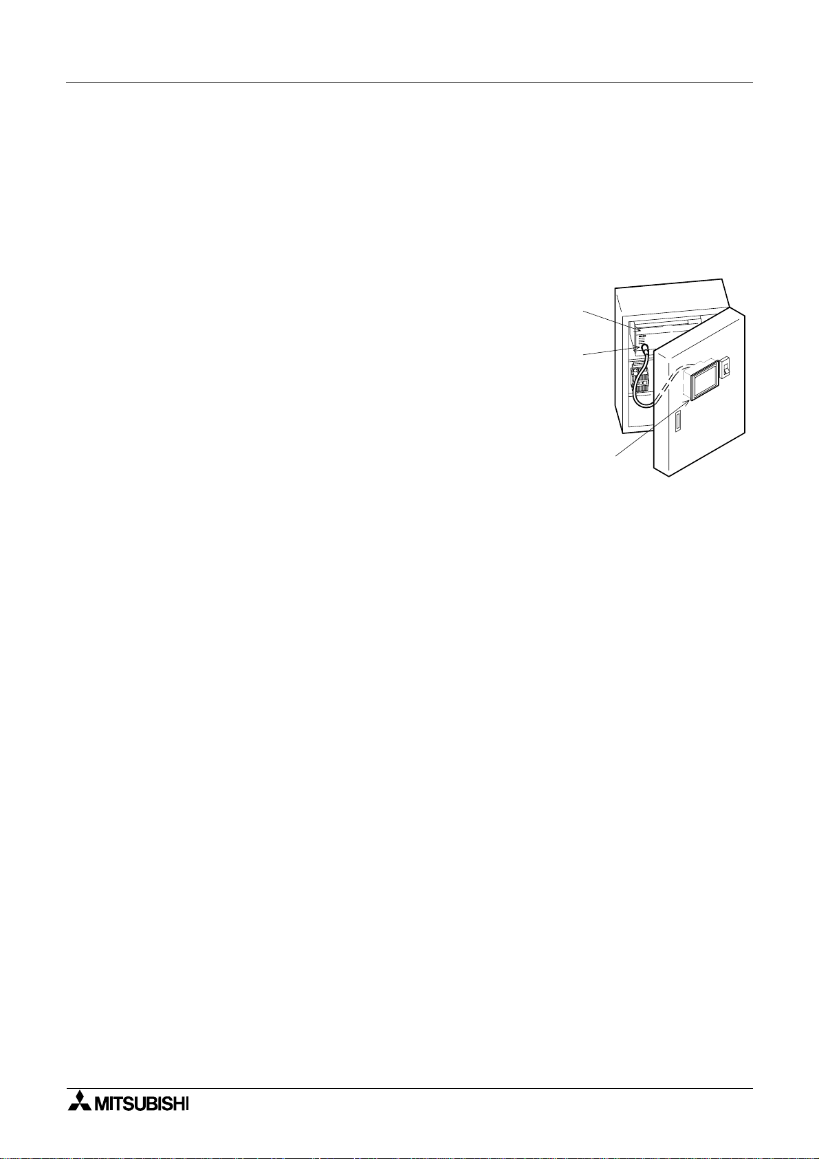
FX or
A Series PLC
Program
connector
GOT main body
Graphic Operation Terminal F940GOT
1. Introduction
This section describes the product configuration and the system configuration of the graphic
operation terminal.
1.1 Outline
The graphic operation terminal (hereafter abbreviated to
GOT) is to be mounted on the face of a control panel or
operations panel, and connected to the programming
port of an FX or A series programmab le cont roll er ( hereafter abbreviated to PLC (except the A0J2))
Va rious devices can be monitored and PLC data
changed through the screens of the GOT.
There are several display screens built-in to the GOT
which offer various functions. In addition user defined
screens can be created.
The user defined screens and the built-in screens (system screens) have the following respective functions.
Introduction 1
User screens
• Screen display function
The following functions can be assigned to each screen. Also the available screens can be
limited using the security function.
Both software packages, FX-PCS-DU/WIN-E (V2.00) available for DU, and the SWoD5CGOTRE-PACK ("o" indicates a numeric not less than "1". ) avai lable for GO T can be used to
create user screens.
Display function
- Up to 500 user defined screens can be displayed. In screen creation, two or more
screens can be overlaid or changed over arbitrarily.
- Simple graphics such as straight lines, circles and rectangles can be displayed, along
with numerics and English, Japanese, Chinese and Korean text. Also bitmaps can be
imported and displayed on screen the F940GOT-SED-E can display screen components
in 8 colors.
Monitor function
- Set values and current values of word devices in the PLC can be displayed in numerics
or bar graphs for monitoring.
- The specified range of the screen components can be displayed in reverse in accordance with the ON/OFF status of bit devices in the PLC.
Data change function
- The numeric data being monitored can be changed.
Switch function
- By manipulating the operation keys in the GOT, bit devices in the PLC can be set to ON
and OFF.
The display panel face can be assigned as touch keys to offe r the switch function.
1-1

Graphic Operation Terminal F940GOT Introduction 1
System screens
• Monitor function
List program (only in the FX Series)
- Programs can be read, written and monitored in the form of an instruction list program.
Buffer memory (only in the FX
and FX
2N
2NC
Series)
- The contents of buffer memories (BFMs) of special blocks can be read, written and monitored.
Device monitor
- The ON/OFF status of each device and the s et value and the current value of each timer,
counter and data register in the PLC can be monitored and changed.
- Specified bit devices can be forced ON or OFF.
Unlike the monitor function described previously, the screen data can be edited by inputting a desired device No. from the keyboard.
• Data sampling function
The current value of spe cified data re gisters are ac quired in a con stant cyc le or w hen the
trigger condition is satisfied.
- The sampling data can be displayed in the form of list or graph.
- The sampling data can be output to a printer in the form of list.
• Alarm function
Alarm messages can be assigned to up to 256 consecutive bit devices in the PLC. When a
bit device becomes ON, the assigned message is displayed (overlapped) on the user
screen.
In addition, a specified user screen can be displayed by setting a corresponding bit device
to ON.
- When a bit device becomes ON, a corresponding message is displayed on the user
screen. The message list can be also displayed.
- Up to 1,000 alarms (turning ON of bit devices) can be stored as the alarm history.
- The alarm frequency each device can be stored as historical data.
* As to 2), the ala rm history can be output to a printer using t he sc reen cre ati on s oftw ar e .
• Other functions
Many other functions are built in.
- A real-time clock is built in, current time and data can be set and displayed.
- The GOT can function as an interface to enable data communication between the PLC
and a personal computer in which the relay ladder creation software is operating. At this
time, the GOT screen can also be displayed.
- The screen contrast and the buzzer sound volume can be adjusted.
1-2

Graphic Operation Terminal F940GOT Introduction 1
n
Important point
Display screens can be created using the following software.
Screens for DU:
FX-PCS-DU/WIN-E V2.00 or later (The F940 main body is compatib le from its first version.)
Screens for GOT-A900:
SWoD5C-GOTRE-PACK ("o" indicates a numeric "1" or more.) (For the F940 main body,
V1.10 or later)
1-3
Graphic Operation Terminal F940GOT Introduction 1
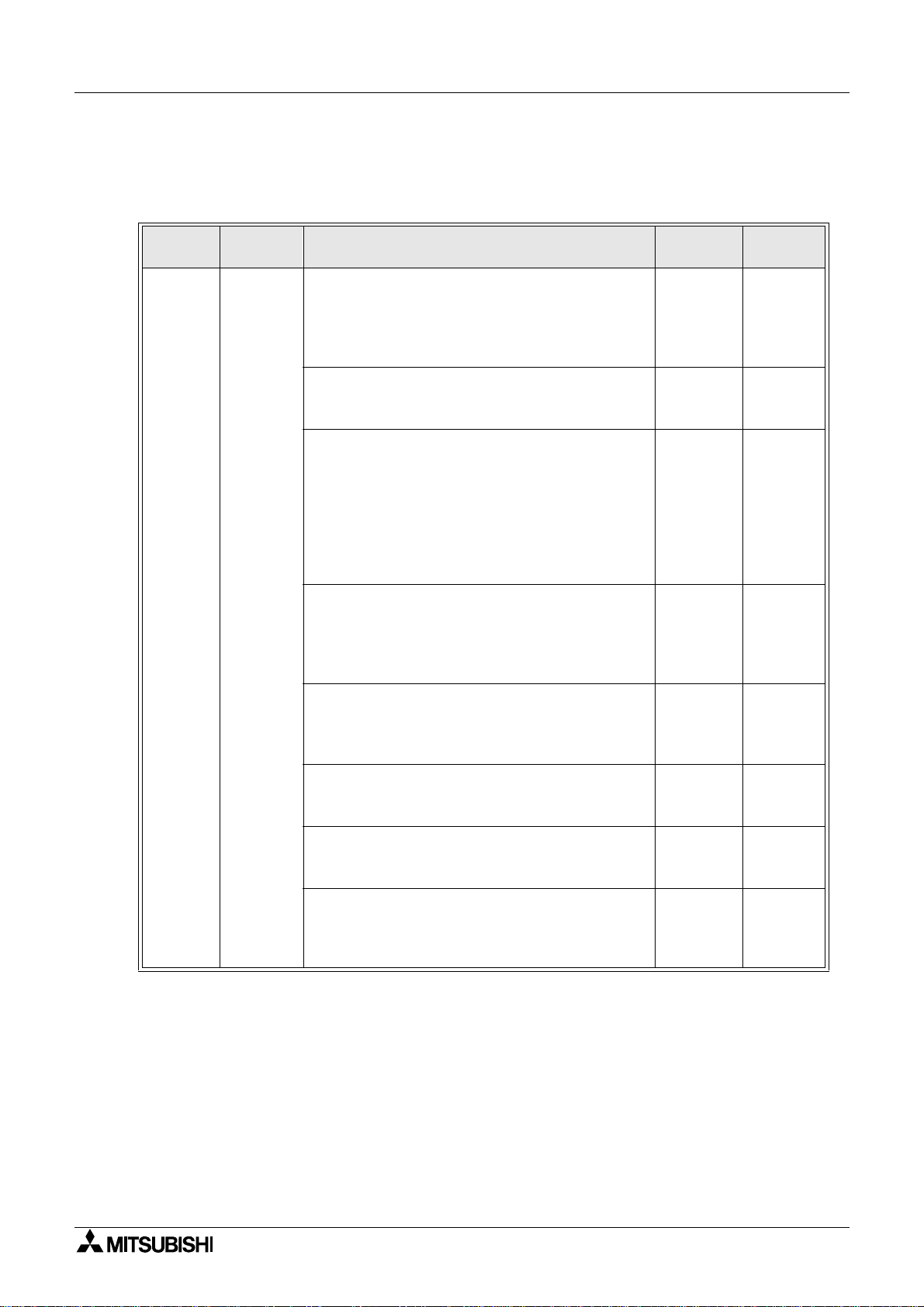
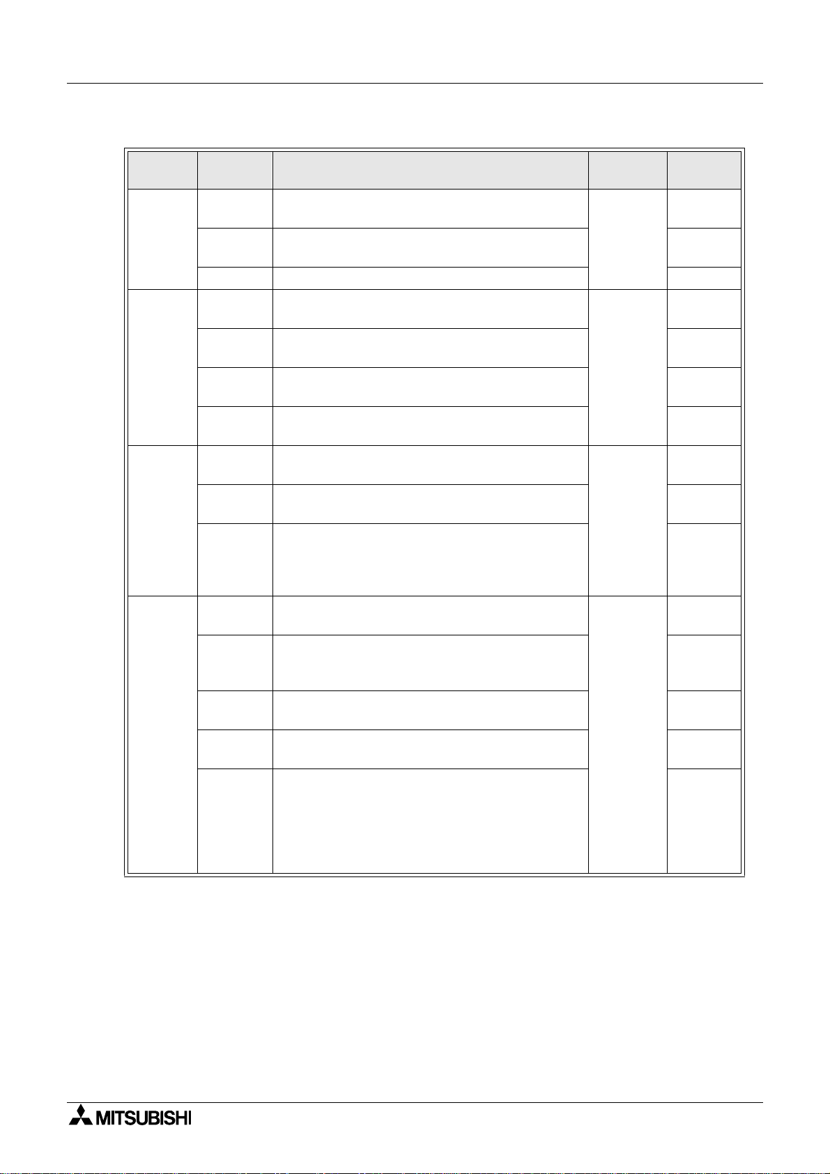
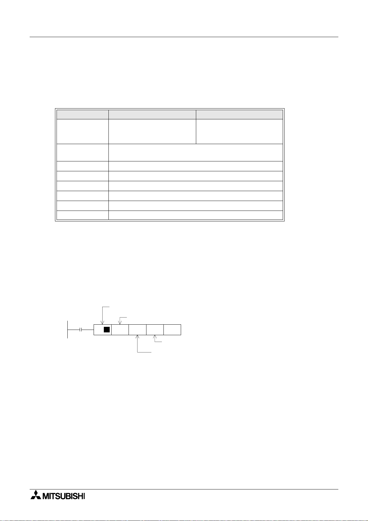
1.2 Function list
The functions described in the previously are divided into six modes shown in the table below.
The operator can use each function by selecting a corresponding mode.
Mode Function Outline of function
Character display
§
Characters such as text, numerics and external
characters are display ed.
§
Japanese, English, Korean and Chinese (continental) are displayed.
Graphic display
§
Graphic such as straight lines, circles rectangles
and bitmaps are display ed.
Monitor function
§
Set values and current values of word devices (T,
C, D, V and Z) in the PLC can be displayed in the
form of numeric, bar graph, trend graph and
panel meter.
§
The color of specified area on the screen is
inverted in accordance with the ON/OFF status
of bit devices (X, Y, M, S, T and C) in the PLC.
Screen
mode
User
screen
display
Data change function
§
Set values and current values of word devices (T,
C, D, V and Z) in the PLC can be changed in the
form of numeric, bar graph, trend graph and
panel meter.
Switch function
§
The ON/OFF status of bit devices (X, Y, M, S, T
and C) in the PLC can be controlled in the format
of momentary, alternate and set/reset.
Screen changeover
§
The display screen can be changed over from
the PLC or a touch key.
Recipe function (data file transfer)
§
Data saved in the GOT can be transferred to the
PLC.
Security function (screen protection function)
§
Screens are displayed only when the entry code
is entered. (This function is available also in the
system screens.)
Reference
sections
3,9,10,12 Note 1
3,9,10,12
3,9,10,12
3,9,10,12
3,9,10,12
3,11,13
3,10,12
2
Remarks
1-4
Graphic Operation Terminal F940GOT Introduction 1
Mode Function Outline of function
§
Programs can be read/written/monitored in the
instruction list program format.
§
Parameters for the program capacity, the memory latch range, etc. can be read/written.
§
Buffer memories (BFMs) in special blocks for the
FX
2N
/FX
Series can be monitored, and their
2NC
set values can be changed.
§
The ON/OFF status of bit devices as well as current values and set values of word devices can
be monitored using device Nos. and comment
expression.
§
Current values and set values of word devices
can be changed using device Nos. and comment
expr essi on.
§
Bit devices (X, Y, M, S, T and C) in the PLC can
be forcedly set to ON or OFF.
§
State (S) Nos. in the ON status are automatically
displayed for monitoring (valid only when the
MELSEC FX Series is connected).
§
The error information in the PLC can be read and
displayed.
HPP
mode
Program
(list)
Parameter
BFM
monitor
Device
monitor
Current
value/
set value
change
Forced
ON/OFF
State
monitor
PLC diagnosis
Reference
sections
4
Remarks
Valid in FX
Series
Valid in FX
Series
Va lid in
FX
/
2N
FX
2NC
Series
Note 1
Valid in FX
Series
Valid in FX
Series
1-5
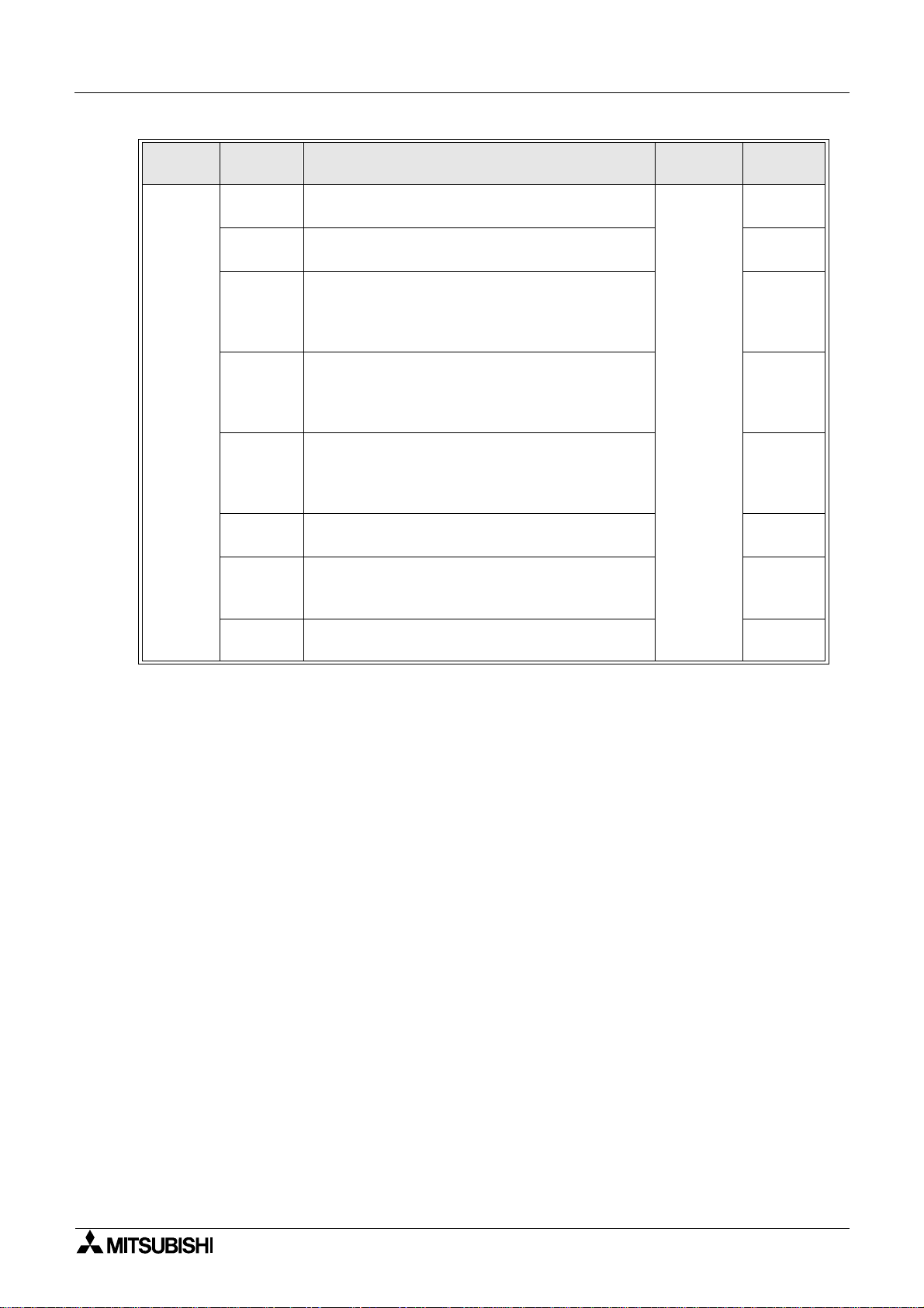
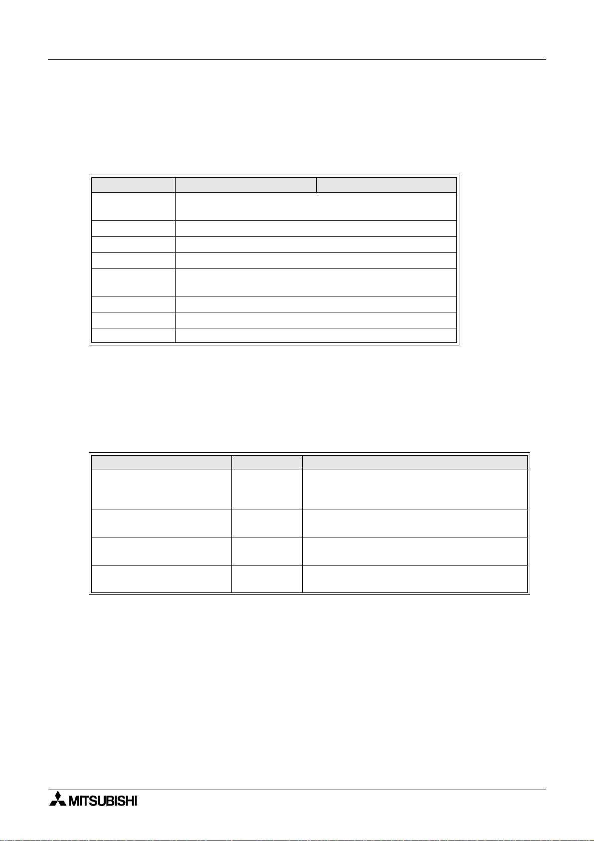
Graphic Operation Terminal F940GOT Introduction 1
Mode Function Outline of function
§
Conditio ns of up to four devices to be sampled
and the sampling start/end time can be set.
§
The sampling result can be displayed in the form
of list or graph.
§
Alarms currently occurred are displayed in the list
in the order of occurrence.
§
The alarm history is saved together with the
occurrence time in the order of occurrence.
§
The number of occurrences of each alarm is
stored.
§
The alarm history is deleted.
§
User screens are displayed in the order of screen
No.
§
The data used in the recipe function can be
changed.
§
The operations can be checked to know whether
key operations, screen changeover, etc. have
been correctly performed on the displayed user
screen.
§
A specified bit device can be kept ON for a specified time.
§
The screen data, the data sampling result and
the alarm history can be transferred between the
GOT and the screen creation software.
§
The sampling result and the alarm history can be
output to a printer.
§
The entry code to protect programs in the PLC
can be registered.
§
The initial setting can be specified for the system
language, the connected PLC, the serial transfer ,
the title screen, the menu screen call, the current
time, the backlight extinguishing time, the buzzer
sound vo lume , the LCD contr ast, the sc reen da ta
clear, etc.
Sampling
mode
Alarm
mode
Test
mode
Other
mode
Condition
setting
display
Data clear§The sampling data can be cleared.
Status
display
History
Frequency
History
clear
Screen list
Data file
Debug
operation
Time
switch
PC
transfer
Printer
output
Entry code
Environment
setting
Reference
sections
5Result
6
7
8
Remarks
Note 2
Note 1:External characters and comments can be created using the screen creation soft-
ware (FX-PCS-DU/WIN-E).
Note 2:The function is valid only when the FX-PCS-DU/WIN-E is used.
* When the PLC is connected via a computer link unit, some functions are restricted.
1-6
Graphic Operation Terminal F940GOT Introduction 1
1.3 Format of manual
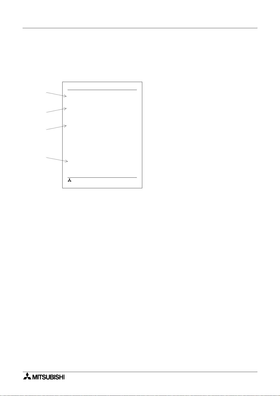
1.3.1 Contents described in manual
This manual is described in the foll owing format. Use each element of the format for index.
Example:
Graphic Operation Terminal F940GO T
a)
b)
c)
d)
2. Startup
2.1 Startup procedure
2.1.1 GOT setup
n
Important point
MITSUBISHI
1.3.2 Abbrev iat ions used in text
Startup 2
a) Section title
Sections 2 to 8 describe operations. Sections 9 to 13 describe the contents
required to create screens.
b) Title
The title explains the contents of each
paragraph.
c) Sub ti tle
d) Important point
Terms used in the text are explained and
supplemented.
2-1
The following ter m s may be abbreviated in the text.
1) MELSEC FX or A Series unit may be abbreviated as "programmable controller" or "PLC".
2) The software kit to create display screens FX-PCS-DU/WIN-E or SWoD5C-GOTRE-PACK
may be abbreviated as "software to create screens" or "screen creation software".
3) A general-purpose computer may be abbreviated as "PC".
4) A floppy disk may be abbrev iat ed as "FD" . A fl oppy disk drive may be abbreviated as "FDD".
5) The graphic operation terminal F940 Series may be abbreviated as "GOT".
6) De vic es in sid e the PLC may be abbreviated as "X" (input), "Y" (ou tput ), "M" (auxil iary relay),
"S" (state), "T" (timer), "C" (counter) and "D" (data register). Output contacts of X,Y, M, S, T
and C are called "bit devices". T, C and D are called "word devices". All of them may be
called "devices".
1-7
Graphic Operation Terminal F940GOT Introduction 1
1.4 Expressions and basic operations of operation keys
The operation keys are expressed as follows in the text.
1.4.1 Expressions of operation keys
1) Touch keys on the screen which are actuated when being touched by fingers are enclosed
with frame.
USER SCREEN MODE,PROGRAM LIST
2) Cursor control keys to be pressed ma y be expressed as follows.
, ,
3) When a same key is pressed several times or a same operation is repeated, the following
expression may be used.
MORE,
4) When an arbitrary numeric within the range of 0 to 9 is to be entered, the following expression may be used.
0 to 9
1.4.2 Basic operations
The common operations in the GOT are shown below.
a)
h)
[ SET CONDITION ] END
SAMPLE COND.
START COND.
END COND.
506
789- CLR
1234
e) f) g)
b)
ENT
a) Function display
The selected mode or function is displayed here.
b) END key
This key terminates the displayed function, and
returns to the previous screen.
c) CLR (clear) key
This key cancels the input of characters and
numeri cs.
c)
d) ENT (enter) key
d)
This key determines the input of alphabets and
numeri cs.
e) Ten-key pad
This pad allows to enter numerics .
f) - (minus) key
g) and (cursor control) keys
h) SET key
When this key is pressed after a character or
numeric has been entered, the keyboard is dis-
played.
1-8
Graphic Operation Terminal F940GOT Introduction 1
1.5 System configuration
This paragraph describes connection of the GOT to a PLC and peripheral unit.
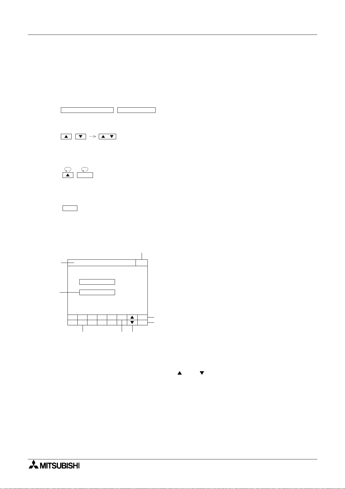
1.5.1 Enlarged view of connector
A PLC and peripheral unit can be connec ted to the following communications ports in the GOT.
1) Communications ports in the GOT
There are communications ports on the side of the GOT.
b)
RS232C
a)
RS422
a) PLC connector (RS-422 connector) D-sub 9-pin, female
This connector allows communication with an FX/A Series PLC.
b) PC connector (RS-232C connector) D-sub, 9-pin, male
This connector links a personal computer with the screen data created using the screen
creation software for data transfer.
When the RS-232C connector in the PC is the 9-pin type, use a data transfer cable FX232CAB-1. When the RS-232C connector in the PC is the half-pitch, 14-pin type, use a
data transfer cable FX-232CAB-2.
This connector is used also when a d ata transfer cable FX
-232-BD is used for an FX
2N
Series PLC or when 1:N connection is adopted with "CPU PORT" in an FX/A Series
PLC.
* When a PLC is connected via a computer link unit, use either of the connectors a) or b)
above.
2N
1-9
Graphic Operation Terminal F940GOT Introduction 1
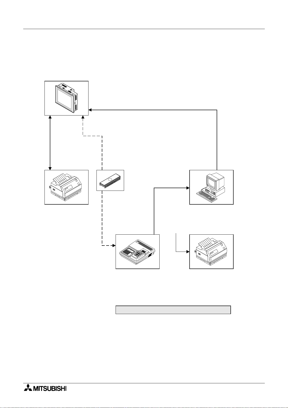
1.5.2 Connection of peripheral units of GOT
The figure below shows the system configuration required to use the GOT with peripheral
devices.
Graphic operation terminal
F940GOT-SWD/LWD-E
Data transfer cable FX-232CAB-1
(when the RS-232C connector in the PC is 9-pin type),
Data transfer cable FX-232CAB-2
(when the RS-232C connector in the PC is half-pitc h, 14-pi n type) or
Data transfer cable F2-232CAB-1
(when the RS-232C connector in the PC is 25-pin type)
Data transfer
cable
FX-232CAB-1
Computer link
(disabled during
RS-232C communication)
Printer
< Dedicated printers >
GT-10A
K6PR(-K), A7(N)PR
< General-purpose printers >
ESC/P
Printer equipped with
RS-232C interface
(Prints out sampling data,
alarm history and alarm
messages.)
Attach a ROM to the
F9GT-40UMB, then
connect it to a connector
provided on the rear face
of the GOT.
EPROM memory
FX-EPROM-4M
(User screens can
be stored using a
general-purpose
ROM writer.)
ROM writer
General-purpose ROM writer
General-purpose personal computer
(screen creation software)
FX-PCS-DU/WIN-E (V2.00) or
SW¨D5C-GOTRE-PACK ("¨" is a
numeric not less than 1.)
Printer
PC-PR201H or its equivalent
ESC/P
* A7(N)PR is available
for the A7PHP/HPG.
(Prints out screen data,
sampling data, etc.)
Peripheral units of GOT
1-10
Graphic Operation Terminal F940GOT Introduction 1
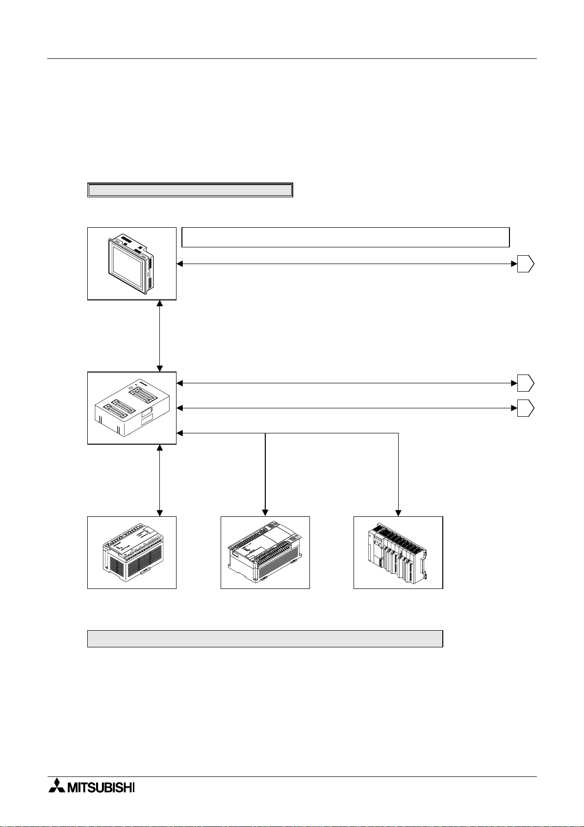
1.5.3 Connection of peripheral units of PLC
When a general-pur pose pe rsonal compute r is directly connec ted to the GOT, the two-por t
interf ace FX-2PIF (two-port interface funct ion) is not required.
When one GOT and one peripheral unit for sequence program creation are used for one PLC,
the two-port interface FX-2PIF is required. The system configuration required in this case is
shown below.
When the two-port interface FX-2PIF is used
Graphic operation terminal
F940GOT-SWD/LWD-E
When the two-port interface function is used, the operation environment should be set for it.
(Refer to the description on "SERIA L P ORT" on t he SET-UP MODE screen.)
Data transfer cable FX-232CAB-1 (when the RS-232C connector in the PC is 9-pin type),
Data transfer cable FX-232CAB-2
(when the RS-232C connector in the PC is half-pitc h, 14-pin type) or
Data transfer cable F2-232CAB-1
(when the RS-232C connector in the PC is 25-pin type)
Two-port interface
FX-2PIF
Connection cable FX-40DU-CAB or Connection cable FX-40DU-CAB -10M
1
Data transfer cable
FX-422CAB0
FX0/FX0S/FX0N/FX2N/
2NC
FX
Series
Program cable FX-20P-CAB
Data transfer cable AC30R4
Data transfer cable FX-422CAB or
Data transfer cable FX-422CAB-150
FX
Series
Programmable controller
A Series (except QnA)
(Refer to Paragraph 1.6.2.)
Motion controller
2
3
1-11
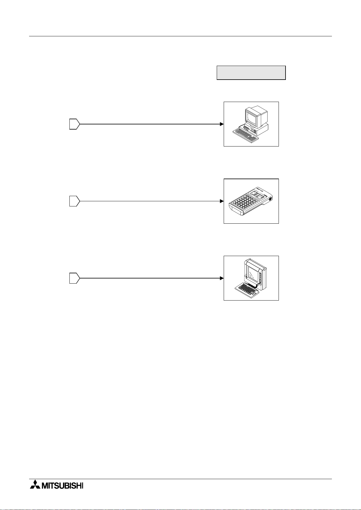
Graphic Operation Terminal F940GOT Introduction 1
Peripheral unit to create
sequence programs
General-purpose
personal computer
* When a general-purpose com put er is di rec tly connected, both
the GOT and the personal computer can be used at the same
time (without using the FX-2PIF).
1
Handy programming
panel FX-10P/20P-E
2
(A Series cannot be used.)
A7PHP/A7HGP
A6GPP/A6PHP
3
2N
The FX
used in the instruction/device
range of the FX Series.
/FX
2NC
Series can be
1-12
Graphic Operation Terminal F940GOT Introduction 1
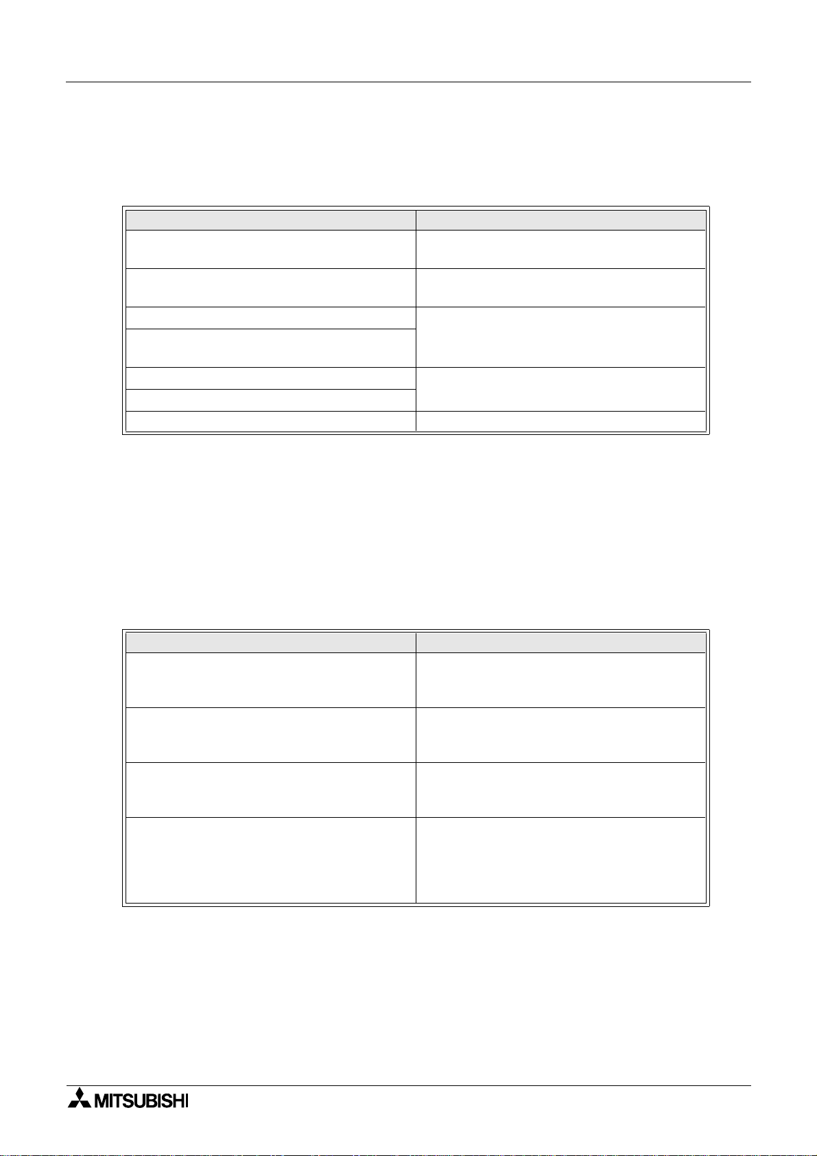
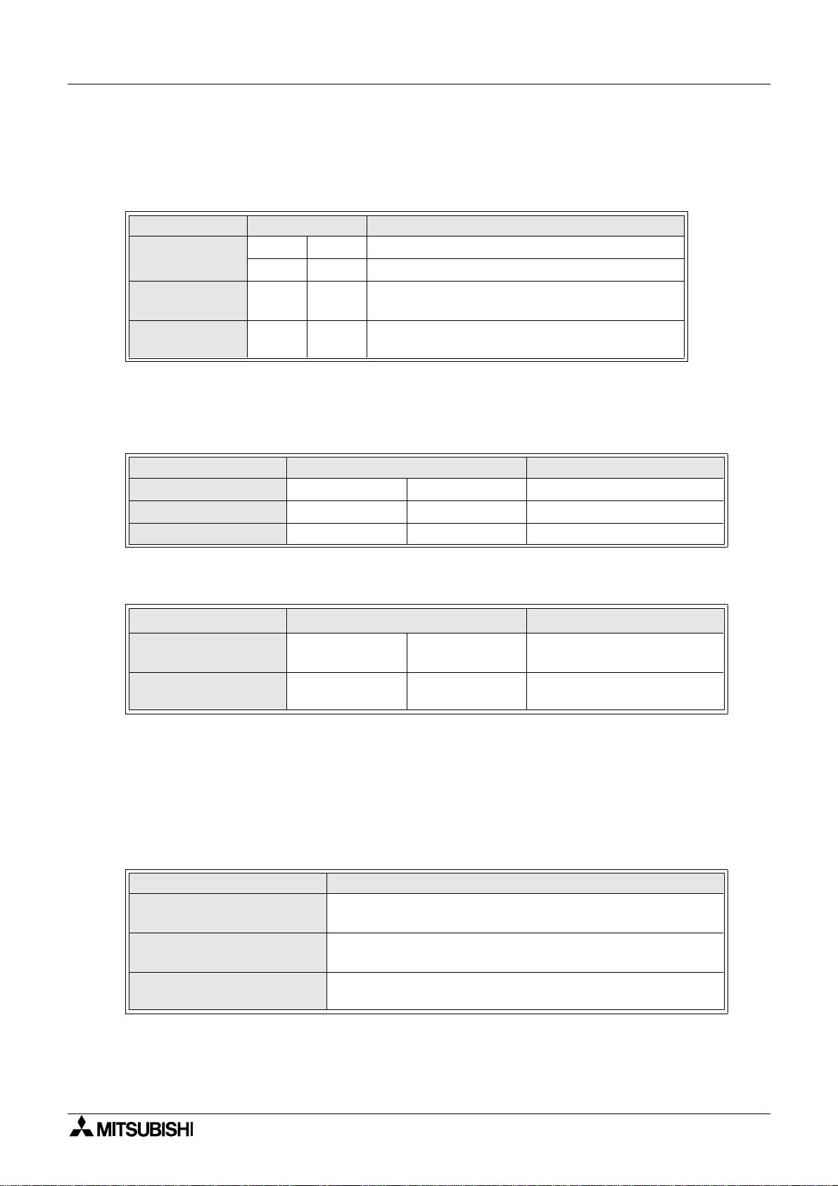
1.6 Connection of PLC
1.6.1 Setting of connected PLC
Set the connected PLC in "PLC TYPE" of "SET-UP MODE" described in P aragraph 2.2.
Connectable PLC Connection type
MELSEC FX/FX
FX
Series manufactured by MITSUBISHI
2NC
MELSEC A Series manufactured by MITSUBISHI
SYSMAC C Series manufactured by OMRON
FLEX-PC N Series manufactured b y FUJI
ELECTRIC
PLC manufactured by Allen-Bradley Co., Inc.
PLC manufactured by Siemens AG
Micro computer board RS-232C port
• For the wiring to the PLC, refer to the hardware manual supplied together with the
F940GOT.
/FX0/FX0S/FX0N/FX2N/
2C
CPU direct (CPU PORT)
CPU direct (CPU PORT) or computer link
(LINK PORT)
Computer link (LINK PORT)
Available soon
1.6.2 Connection of MELSEC FX/A Series (CPU PORT)
Connect the GOT to the programming connector in the PLC, and perform communication.
This communication method is easy because sequence programs, setting and interface are
not required once the connected PLC is set in the operation environment setting (on the SETUP MODE screen).
Series name Connection type
CPU PORT (RS422)
FX/FX
FX
/FX0/FX0S/FX0N/FX2N/FX
2C
(when FX2N-232-BD is used)
2N
AnN,AnA,AnS,AnSJ,AnSH,A1SJH,A2C,A2CJ,
A0J2H,AnU,AnUS,A2USH,A1FCCPU
Motion controller
A171SCPU-S3
A171SHCPU
A172SHCPU
A272UHCPU
2NC
Series
(In 1:N connection, select "CPU PORT
(RS232C)" for the second and fourth PLCs.)
CPU PORT (RS232)
(In 1:N connection, select "CPU PORT
(RS232C)" for the second and fourth PLCs.)
CPU PORT (RS422)
(In 1:N connection, select "CPU PORT
(RS232C)" for the second and fourth PLCs.)
CPU PORT (RS422)
(In 1:N connection, select "CPU PORT
(RS232C)" for the second and fourth PLCs.)
1-13
Graphic Operation Terminal F940GOT Introduction 1
1.6.3 Connection of MELSEC A Series (LINK PORT)
When the GOT is connected to the MELSEC A Series PLC via a computer link unit, the following setting is required.
• Setting of computer link unit
Set the communication format of the computer link unit as shown below.
Used port When RS-422 is used When RS-232C is used
Mode setting
switch No.
Transmission
speed
Data bit 7 bits
Stop bit 1 bit
Parity bit Even
Sum check Provided
Write during r un Possible
Station No. 00 to 0F (in accordance with setting in GOT) *2
5
RS-422: Format 1
RS-232C: No-procedure *1
1
RS-422: No-procedure
RS-232C: Format 1 *1
19200bps
*1 For wiring to the PLC, refer to the hardware manua l sup plied t ogethe r with t he F940GOT.
*2 The GOT station No. can be set in "SET-UP MODE" (Refer to Paragraph 2.2.).
• Caution: When RS-232C is connected the GOT does not control CD signals. Accordingly,
when the RS-232C is connected, the buffer memory in the computer link unit should be set
so that CD signals are not checked.
Example: When I/O signals in the computer link unit are 80 (H) to 9F (H)
Write to buffer memory
Computer link unit connection point
X87
TO H8 H10B K1 K1
P
K1: CD terminal will not be checked.
10B (H): CD terminal will be checked.
• Restriction of functions
When a computer link unit is connected, the following functions are disabl ed in the GOT.
- Index registers (V and Z) cannot be monitored, and their current values cannot be
changed.
- When the RS-232C is connected, the printer output function of the GOT is disabled.
1-14
Graphic Operation Terminal F940GOT Introduction 1
1.6.4 Connection of SYSMAC C Series
When the GOT is connected to the SYSMAC C Series PLC manufactured by OMRON, the following setting is required.
• Setting of host link unit
Set the communication format of the host link unit as shown below.
Used port When RS-422 is used When RS-232C is used
Transmission
speed
Data bit 7bit
Stop bit 2bit
Parity bit Even
Communication
mode
Command level Level 1, 2 or 3
Procedure 1:N procedure
Unit No. 00 to 15 (BCD) (in accordance with setting in GOT) *1
19200bps
Host link mode
* Only a model in which these set items are offered can be connected to the GO T.
*1 The GOT station No. can be set in "SET-UP MODE" (Refer to Paragraph 2.2.).
Setting example:
Set the communication format while referring to setting examples of each
host link unit in the C Series.
- In the case of CQM1-CPU . . . Setting by data memory (DM)
Set item Set value Remarks
Standard communication condition
(RS232C: DM6645)
Communication condition
(RS232C: DM6646)
Send delay time
(RS-232C: DM6647)
Unit No.
(RS-232C: DM6648)
0001H
0304H
0000H
(initial status)
00XXH
Mode specification: Host link
Communication condition: In accordance with
DM6646
Transmission format: 7 data bits and 2 stop bits
Parity: EvenTransmission speed: 19,200 bps
0 second
xx: Two-digit BCD (in accordance with setting in
GOT)
1-15
Graphic Operation Terminal F940GOT Introduction 1
- In the case of host link unit attached to C200H base . . . Setting by each switch
(when C200H-LK201-V1/C200H-LK202-V1 is used)
Setting of switches on front face (common between C200H-LK201-V1 and C200H-LK202V1)
Set item Switch setting Remarks
Unit No.
Transmission
speed
Communication
condition
SW1 *1 Upper digit BCD
SW2 *1 Lower digit BCD
SW3 6 19200bps
SW4 2
7-bit ASCII and 2 stop bits
Parity: EvenCommand level: 1, 2 or 3
*1 Equivalent to station No. setting in the GOT
Setting of switches on rear face (C200H-LK201-V1)
Set item Switch setting Remarks
Procedure
5 V power supply
CTS changeover
DIP. SW No.3 ON 1:N procedure
DIP. SW No.4 OFF 5 V is not supplied.
Selector switch Up side External
(C200H-LK202-V1)
Set item Switch setting Remarks
Procedure
Connection of termi-
nal resistor
Right selector
switch
Left selector
switch
Lower side 1:N procedure
Up side Provided
• Cautions
Operation mode of the SYSMAC C Series
When changing the current value and the set value of each device in the C Series PLC, the
PLC should be set to the monitor mode.
If the GOT is connected and the C Series PLC is started up in the r unning mode, the GOT
sets automatically the PLC to the monitor mode so that the data can be changed.
Mode of PLC at startup GOT operation
Running m ode
Monitor mode
Program mode
The GOT changes over the PLC from the running mode to the
monitor mode to enable data change.
The PLC remains in the monitor mode, and data change is
enabled.
The PLC remains in the program mode, and data change is
enabled.
1-16
 Loading...