

Mitsubishi Electric F930GOT-BWD, F940GOT-SWD, F940WGOT-TWD, F940GOT-SBD-H, F940GOT-LBD-H Operation Manual
...
OPERATION MANUAL
GOT-F900

Graphic Operation Terminal GOT-F900
Foreword
• This manual contains text, diagrams and explanations which will guide the reader in the
correct installation and operation of GOT -F900.
• Before attempting to install or use GOT-F900 this manual should be read and understood.
• If in doubt at any stage of the installation of GOT-F900 always consult a professional
electrical engineer who is qualified and trained to the local and national standards which
apply to the installation site.
• If in doubt about the operation or use of GOT-F900 please consult the nearest Mitsubisi
Electric distributor.
• This manual is subject to change without notice.

Graphic Operation Terminal GOT-F900
GRAPHIC OPERATION TERMINAL
GOT-F900
OPERATION MANUAL
Manual number : JY992D94701
Manual revision : A
Date : April 2001
i

Graphic Operation Terminal GOT-F900
ii

Graphic Operation Terminal GOT-F900
FAX BACK
Mitsubishi has a world wide reputation for its efforts in continually developing and pushing
back the frontiers of industrial automation. What is sometimes overlooked by the user is the
care and attention to detail that is taken with the documentation. However, to continue this
process of improvement, the comments of the Mitsubishi users are a lways welcomed. This
page has been designed for you, the reader, to fill in your comments and fax them back to us.
We look forward to hearing from you.
Fax numbers: Your name....................................................
Mitsubishi Electric.... .....................................................................
America (01) 847-478-2253 Your company ..............................................
Australia (02) 638-7072 .....................................................................
Germany (0 21 02) 4 86-1 12 Your location:................................................
South Africa (0 27) 11 444-0223 .................... ................................. .. ..............
United Kingdom (01707) 278-695
Please tick the box of your choice
What condition did the manual arrive in?
Will you be using a f o lder to store the manual?
What do you think to the manual presentation?
Are the explanations understandable?
Which explanation was most difficult to understand:..................................................................
....................................................................................................................................................
Are there any diagrams which are not clear?
If so,which:..................................................................................................................................
What do you think to the manual layout?
If there one thing you would li ke to see improved, what is it?.....................................................
....................................................................................................................................................
....................................................................................................................................................
Could you find the information you required easily using the index and/or the contents, if
possible please identify your experience: ...................................................................................
....................................................................................................................................................
....................................................................................................................................................
....................................................................................................................................................
....................................................................................................................................................
¨
¨
¨
¨
¨
¨
Good
Yes
Tidy
Yes
Yes
Good
Minor damage
¨
No
¨
Unfriendly
¨
Not too bad
¨
No
¨
Not too bad
¨
Unusable
¨
Unusable
¨
Unhelpful
¨
Do you have any comments in general about the Mitsubishi manuals? ............... .. ....................
....................................................................................................................................................
....................................................................................................................................................
....................................................................................................................................................
....................................................................................................................................................
Thank you for taking the time to fill out this questionnaire. We hope you found both the product
and this manual easy to use.
iii

Graphic Operation Terminal GOT-F900
iv
Graphic Operation Terminal GOT-F900
Guidelines for the Safety of the User and Protection of the Graphic operation
terminal GOT-F900
This manual provides information for the use of the Graphic operation terminal GOT-F900. The
manual has been writte n to be use d by trained and compe tent personnel. T he definition of
such a person or persons is as follows;
a) Any engineer who is responsible for the planning, design and construction of automatic
equipment using the product associated w ith this manual should be of a com petent
nature, trained and qualified to the loc al and national sta ndards required to fulfill that
role. These engineers should be fully aware of all aspects of safety with regards to
automated equipment.
b) Any commissioning or service engineer must be of a competent nature, trained and
qualified to the local an d nationa l standards required to fulfill tha t job. These engineers
should also be trained in the use and maintenance of the completed product. This
includes being completely f amili ar with all ass ociated docume ntation for the said product.
All maintenance should be carried out in accordance with established safety practi ces.
c) All operators of the completed equipment should be trained to use that product in a safe
and coordinated manner in compliance to established safety practices. The operators
should also be familiar with documentation which is connected with the actual operation
of the completed equipment.
Note : Note: the term ‘completed equipment’ refers to a third party constructed device which
contains or uses the product associated with this manual.
Notes on the Symbols Used in this Manual
At various times through out this manual cer tain s ymbols will be used to highlight p oints of
information which are intended to ensure the users personal safety and protect the integrity of
equipment. Whenever any of the following symbols are encountered its associated note must
be read and understood. Each of the symbols used will no w be lis ted with a brief description of
its meaning.
Hardware Warnings
1) Indicates that the identified danger WILL cause physical and property damage.
2) Indicates that the identified danger could POSSIBLY cause physical and property
damage.
3) Indicates a point of further interest or further explanation.
Software Warnings
4) Indicates special care must be taken when using this element of software.
5) Indicates a special point which the user of the associate software element should
be aware of.
6) Indicates a point of interest or further explanation.
v

Graphic Operation Terminal GOT-F900
• Under no circumstances will Mitsubishi Electric be liable or responsible for any
consequential damage that may arise as a result of the installation o r use of t his equi pment.
• All examples and diagrams shown in this manual are intended only as an aid to
understanding the text, not to guarantee operation. Mitsubishi Electric will accept no
responsibility for actual use of the product based on these illustrative examples.
• Owing to the very great variety in possible application of this equipment, you must satisfy
yourself as to its suitability for your specific application.
vi

Graphic Operation Terminal GOT-F900 Contents
Manual configuration and various data ........................................................1
1. Introduction .........................................................................................1-1
1.1 Outline..............................................................................................................1-1
1.2 Format of manual.......................................................... .. .................................1-3
1.2.1 Contents described in manual.............................................................................1-3
1.2.2 Abbreviations used in text ...................................................................................1-3
1.3 Expressions and basic functions of operation keys ......................................... 1-4
1.3.1 Expressions of operation keys ............................................................................1-4
1.3.2 Basic operations..................................................................................................1-4
1.4 System configuration .......................................................................................1-5
1.4.1 Connection of peripheral units of GOT................................................................1-5
1.5 Connectable PLC.............................................................................................1-6
1.6 GOT version upgrade history........................... ................................. .. .............1-9
1.7 Screen creation software version upgrade history.........................................1-11
1.8 Preservation of screen data and backup .......................................................1-13
2. Specifications......................................................................................2-1
2.1 General specifications......................................................................................2-1
2.2 Display section specifications ..........................................................................2-2
3. Outside dimensions.............................................................................3-1
4. Part names..........................................................................................4-1
4.1 Front panel.......................................................................................................4-1
4.2 Rear panel.......................................................................................................4-1
4.3 Functions of connectors........................ .......................... ......................... ........4-2
5. Installation...........................................................................................5-1
5.1 Panel cut dimension.........................................................................................5-1
5.2 Installation........................................................................................................5-2
6. Function ..............................................................................................6-1
6.1 Function list......................................................................................................6-1
7. Start up ...............................................................................................7-1
7.1 Start up procedure...........................................................................................7-1
7.2 Operation environment setting.........................................................................7-3
7.3 Each mode selection procedure ......................................................................7-9
7.4 Security function (screen protection function)................................................7-11
7.4.1 Upgrading of security function...........................................................................7-13
8. Creation of Display Screens................................................................8-1
8.1 Outline of compatibility of screen data.......................... ...................................8-2
8.1.1 Functions dedicated to screen creation software FX-PCS-DU/WIN-E................8-3
8.1.2 Common functions ..............................................................................................8-4
8.1.3 Functions dedicated to GT Designer...................................................................8-7
8.2 Transfer of screen data........................... ......................... ................................8-8
8.3 Misappropriation of screen data.....................................................................8-10
8.4 Use of data in FX-50DU-TK(S)-E...................................................................8-10
8.5 Concept on screen display........... ..................................................................8-11
8.5.1 Screen display position .....................................................................................8-11
8.5.2 Number of display screens and screen Nos......................................................8-11
8.5.3 Number of display elements and data capacity ................................... ...... ........8-11
8.5.4 Attribute of display element............................................. ....... ...... ....... ...... ....... . 8-12
8.6 Screen call function and overlay functio n......................................................8-15
8.6.1 The writing function of the initial display screen number
(GT Designer is used). ......................................................................................8-16
8.6.2 Screen call function...........................................................................................8-17
8.6.3 Overlay function ................................................................................................8-18
vii

Graphic Operation Terminal GOT-F900 Contents
8.7 Control devices and system inf o rmation........................................................8-26
8.7.1 Control device (setting in FX-PCS-DU/WIN-E) .................................................8-26
8.7.2 System information (setting in GT Designer) ....................................................8-29
9. Screen mode .... ............ ............ ............ ............ ............ ............ ...........9-1
9.1 Display format..................................................................................................9-1
9.2 Display size......................................................................................................9-2
9.3 Outline of screen mode................................ ................................. .. .................9-4
9.4 Number of registered screen construction elements .......................................9-6
9.5 Change of displ a ye d d ata .................... .. .. .............. .. .. ............. ... ......................9-8
9.5.1 Common contents in data change.......................................................................9-8
9.5.2 Decimal point input function ..............................................................................9-10
9.5.3 Key window display position specification.........................................................9-11
9.5.4 Creation of key window .....................................................................................9-13
9.6 Numeric setting completion flag.....................................................................9-16
9.6.1 When FX-PCS-DU/WIN-E is used ....................................................................9-16
9.6.2 When GT Designer is used ............................................................................... 9-17
10. HPP Mode.........................................................................................10-1
10.1 O utline of HPP mode ........................................................................ .. ...........10-1
10.2 PROGRAM LIST............................................................................................10-2
10.3 PARAMETER...............................................................................................10-11
10.4 DEVICE MONITOR................................. .. ...................................................10-12
10.4.1 Device/comment monito r .................................... ....... ...... ....... ...... ....... ...... ...... 10-12
10.4.2 Changing set values and current values of T, C and D................................... 10-14
10.4.3 Forced ON/OFF.................................................. ....... ...... ....... ...... ....... ...... ...... 10-16
10.5 LIST MONITOR ...........................................................................................10-17
10.6 ACTIVE STATE MONITOR .........................................................................10-18
10.7 BFM MONITOR ...........................................................................................10-19
10.8 PC DIAGNOSIS...........................................................................................10-20
11. Sampling Mode.................................................................................11-1
11.1 Outline of sampling mode ..............................................................................11-1
11.2 Outline of sampling condition setting .............................................................11-3
11.2.1 SAMPLE COND. ...............................................................................................11-5
11.2.2 START COND...................................................................................................11-6
11.2.3 END COND.......................................................................................................11-7
11.2.4 SAMPLING DEV. ..............................................................................................11-9
11.3 Display of sampling result............................................................................11-10
11.3.1 DISPLAY LIST.................................................................................................11-10
11.3.2 DISPLAY GRAPH ........................................................................................... 11-10
11.4 CLEAR DAT A..............................................................................................11-11
11.5 Control signals in PLC ............... ................................. .. ...............................11-12
11.5.1 When FX-PCS-DU/WIN-E is used ..................................................................11-12
11.5.2 When GT Designer..........................................................................................11-12
12. Alarm Mode.......................................................................................12-1
12.1 Outline of alarm function................................................................................12-1
12.2 Alarm function in screen mode............................. .........................................12-2
12.2.1 Set item.............................................................................................................12-3
12.2.2 Alarm history clear using key code....................................................................12-5
12.3 Alarm function in alarm mode ........................................................................12-7
12.3.1 Operation when alarms have occurred .............................................................12-8
12.3.2 Alarm list............................................................................................................12-9
12.3.3 Alarm history display .......................................................................................12-11
12.3.4 Alarm frequency display.................................................................................. 12-12
12.3.5 Alarm history clear...........................................................................................12-13
viii

Graphic Operation Terminal GOT-F900 Contents
13. Test Mode.........................................................................................13-1
13.1 Outline of test mode.......................................................................................13-1
13.2 USER SCREEN........................................................................ ...... ...............13-2
13.3 DATA BANK...................................................................................................13-3
13.4 DEBUG..........................................................................................................13-4
13.5 Communication monitor (F940GOT, F940WGOT)........................................13-7
14. Other Mode.......................................................................................14-1
14.1 Outline of other mode ....................................................................................14-1
14.2 SET TIME SWITCH .......................................................................................14-2
14.3 DATA TRANSFER.........................................................................................14-3
14.4 PRINT OUT.................. .. .. ............. ... .. ............. .. .. .............. .. .. ............. ... .. .......14-4
14.5 ENTRY CODE ...............................................................................................14-6
14.6 SET UP MODE ..............................................................................................14-7
15. Connection to Bar Code Reader.......................................................15-1
15.1 Outline of function..........................................................................................15-1
15.2 Applicable version..........................................................................................15-1
15.3 Connection.....................................................................................................15-1
16. Screen Hard Copy Function..............................................................16-1
16.1 Outline of hardware copy operation...............................................................16-1
16.2 Applicable version..........................................................................................16-2
16.3 Starting and aborting printing.........................................................................16-2
16.3.1 Start and abortion by triggers............................................................................16-2
16.3.2 Start and abortion by touch switches ................................................................16-2
16.3.3 Hard copy output signal (GT Designer).............................................................16-3
16.3.4 Printing image ...................................................................................................16-5
17. Observe status function ....................................................................17-1
17.1 Outline of observe status function..................................................................17-1
17.2 Applicable version..........................................................................................17-2
17.3 Observe status cycle......................................................................................17-2
17.4 Setting the triggers.................................. .......................................................17-2
17.4.1 Setting the operation .........................................................................................17-3
17.5 Trigger and number of devices.......................... .. ..........................................17-6
17.6 Cautions.........................................................................................................17-7
17.7 Use example (utilization of clock data) ..........................................................17-8
18. Creation of Display Screens (FX-PCS-DU/WIN-E)...........................18-1
18.1 Element li st ............. .. ... ............. .. .. .............. .. .. ............. .. ... ............. .. .. ............18 -1
18.2 Application and setting item............................... .. ..........................................18-4
18.3 Registration of object .....................................................................................18-6
18.4 Display objects...............................................................................................18-7
18.4.1 Text ...................................................................................................................18-7
18.4.2 Line....................................................................................................................18-8
18.4.3 Box....................................................................................................................18-9
18.4.4 Filled Box.........................................................................................................18-10
18.4.5 Circle...............................................................................................................18-11
18.4.6 Filled Circle......................................................................................................18-12
18.4.7 Image .............................................................................................................. 18-13
18.4.8 Date and time..................................................................................................18-14
18.5 Data display objects.....................................................................................18-15
18.5.1 Library Text .....................................................................................................18-15
18.5.2 Number............................................................................................................18-17
18.5.3 Bar Graph........................................................................................................18-20
18.5.4 Circle Graph ....................................................................................................18-23
ix

Graphic Operation Terminal GOT-F900 Contents
18.5.5 Proportional Bar Graph ................................................................................... 18-24
18.5.6 Proportional Pie Graph....................................................................................18-25
18.5.7 Panel Meter..................................................................................................... 18-26
18.5.8 Indicator...........................................................................................................18-27
18.5.9 Label Indicator.................................................................................................18-28
18.5.10 Text Indicator...................................................................................................18-29
18.5.11 Image Indicator................................................................................................ 18-30
18.5.12 Overlay Screen................................................................................................ 18-31
18.5.13 Library Image ..................................................................................................18-32
18.5.14 Trend Graph (Sampling)..................................................................................18-33
18.5.15 Trend Graph (Total).........................................................................................18-36
18.5.16 Ascii................................................................................................................. 18-38
18.6 Data transfer objects....................................................................................18-41
18.6.1 Touch Key.......................................................................................................18-42
18.6.2 Switch..............................................................................................................18-46
18.6.3 Send Data Bank (recipe function) ...................................................................18-48
18.6.4 Write Constant.................................................................................................18-49
18.6.5 Increment ........................................................................................................ 18-50
18.6.6 Decrement....................................................................................................... 18-51
18.6.7 Data Setting.....................................................................................................18-52
18.6.8 Keyboard.........................................................................................................18-55
18.6.9 Change Screen ...............................................................................................18-59
18.6.10 Alarm history display function..........................................................................18-60
18.6.11 Alarm list display function................................................................................ 18-62
18.6.12 Buzzer.............................................................................................................18-64
18.7 Text library ...................................................................................................18-65
18.8 Image library................................................................................................18-66
18.9 Data file........................................................................................................18-67
19. Changeover of Display Screen (FX-PCS-DU/WIN-E).......................19-1
19.1 Outline of changeover of display screen............................ ............................19-1
19.2 "Change Screen" object.................... .. ................................. .. ........................19-2
19.2.1 Contents of setting ............................................................................................ 19-2
19.2.2 Operation of screen changeover.......................................................................19-4
19.2.3 Timing of screen changeover............................................................................19-5
19.3 Screen changeover by touch key.............................................. .....................19-6
19.4 Screen changeover from PLC......................................... ...............................19-9
19.4.1 Screen changeover using bit devices................................................................19-9
19.4.2 Screen changeover by data ............................................................................ 19-11
19.5 Screen changeover by screen No. stored in memory..................................19-13
19.6 Changeover to system screen.....................................................................19-15
19.6.1 Display of system screen ................................................................................19-15
19.7 Application of screen changeover................................................................19-16
20. Creation of Display Screen (GT Designer)........................................20-1
20.1 Project auxiliary settings ................................................................................20-1
20.2 Element li st ............. .. ... ............. .. .. .............. .. .. ............. .. ... ............. .. .. ............20 -6
20.3 Application and setting item............................... .. ..........................................20-8
20.4 Figure display function.................................................................................20-10
20.5 Data display function....................................................................................20-11
20.5.1 Display of numerics.........................................................................................20-11
20.5.2 ASCII code display function ............................................................................ 20-13
20.5.3 Clock display function... ...... ....... ...... ....... ...................................... ....... ...... ...... 20 -1 6
20.5.4 Comment display function...............................................................................20-17
20.5.5 Alarm history display function..........................................................................20-18
20.5.6 Alarm list display function................................................................................20-20
20.5.7 Part display function........................................................................................ 20-22
x

Graphic Operation Terminal GOT-F900 Contents
20.5.8 Lamp display function......................................................................................20-23
20.5.9 Panel meter display function...........................................................................20-24
20.6 Graph display function.................................................................................20-25
20.6.1 Trend graph..................................................................................................... 20-26
20.6.2 Line graph .......................................................................................................20-27
20.6.3 Bar graph.........................................................................................................20-28
20.6.4 Statistics graph display function...................................................................... 20-30
20.7 Touch ke y s................... .. .. ............. ... .. ............. .. .. .............. .. .. ............. ... .. .....20-31
20.7.1 Common items for all touch keys....................................................................20-32
20.7.2 Bit function.................... ...... ....... ...... ....... ...... ...... ....... ...... ....... .........................20-34
20.7.3 Word function ..................................................................................................20-36
20.7.4 Creation of keys to enter numerics and ASCII codes......................................20-37
20.8 Data input function.................................. ................................. ....................20-38
20.8.1 Numerical input function.................................................................................. 20-38
20.8.2 ASCII code input function................................................................................20-40
20.9 Creation of comment....................................................................................20-43
20.10 Recipe function ............................................................................................20-44
21. Changeover of Display Screen (GT Designer)..................................21-1
21.1 Outline of changeover of display screen............................ ............................21-1
21.2 Changeover of display screen .......................................................................21-2
21.2.1 Contents of setting ............................................................................................ 21-2
21.2.2 Contents of screen changeover operation ........................................................21-2
21.3 Changeover of base screen (changeover from PLC) ....................................21-3
21.3.1 Outline of changeover of base screen...............................................................21-3
21.3.2 Example of basescreen changeover.................................................................21-4
21.4 Screen changeover by touch key.............................................. .....................21-5
21.4.1 Changeover using a fixed value........................................................................ 21-5
21.4.2 Changeover to upper hierarchy.........................................................................21-6
21.5 Changeover to system screen.......................................................................21-7
21.5.1 Display example of system screen....................................................................21-7
21.6 Application of screen changeover..................................................................21-8
21.6.1 Application example 1.......................................................................................21-8
21.6.2 Application example 2.....................................................................................21-10
22. Appendix...........................................................................................22-1
22.1 Number of registered screen construction elemen ts................................... ..22-1
22.2 Comparison with screen creation software....................................................22-3
22.2.1 Differences in functions among display units and connected PLC....................22-5
22.3 System Screen No.........................................................................................22-8
22.4 Key Code List.................................................................................................22-9
22.5 Key code list used in each object.................................................................22-10
xi

Graphic Operation Terminal GOT-F900 Contents
xii
Graphic Operation Terminal GOT-F900
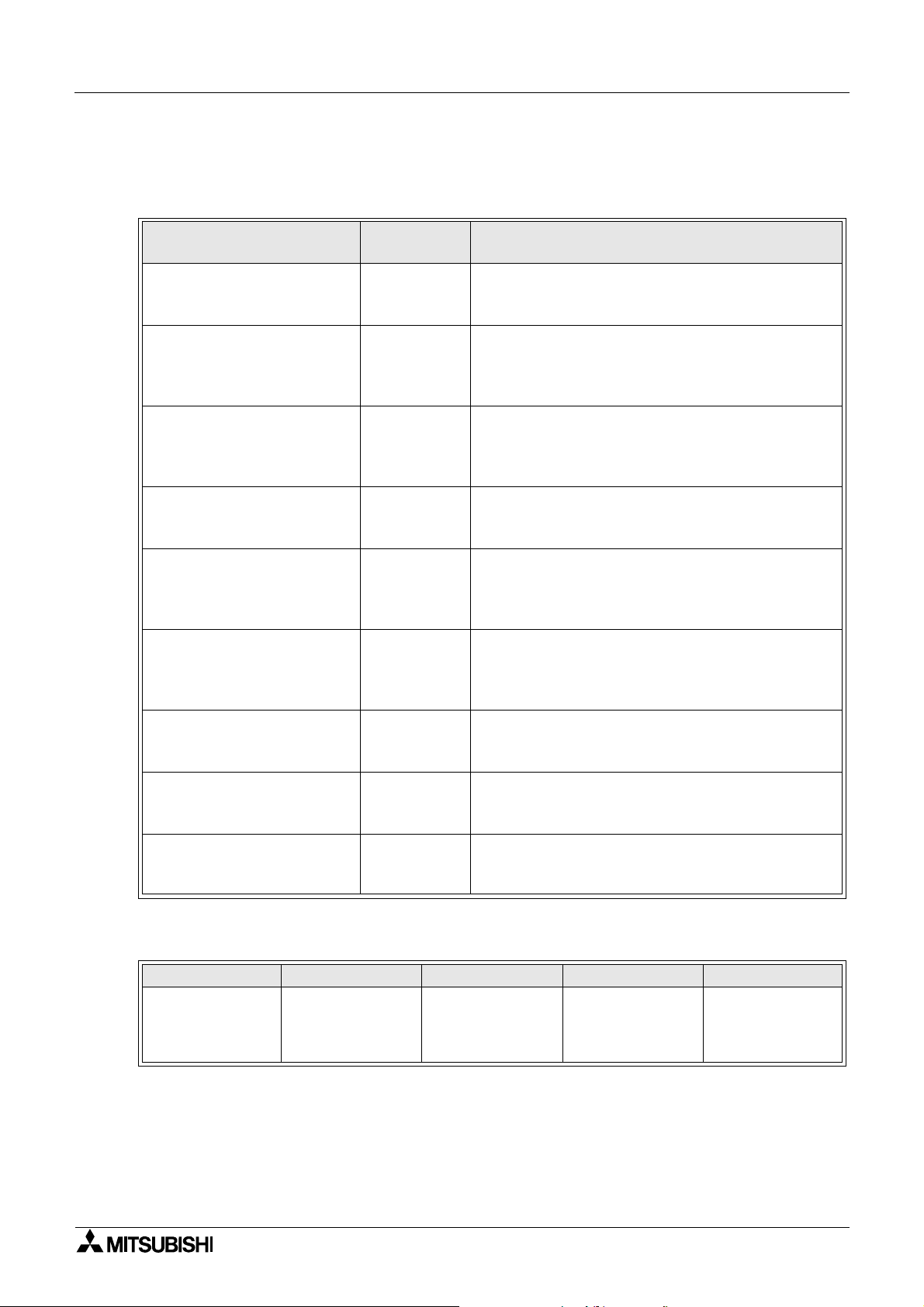
Manual configuration and various data
The configuration of the manual s relating to this product is as shown below.
Manual configuration and various data
Manual name
Manual
number
F930GOT Series
Installation Manual
JY992D95701
(supplied with product)
F940GOT Series
(F940GOT-*WD-E)
Installation Manual
JY992D94201
(supplied with product)
F940GOT Handy Series
(F94*GOT-BD-H-E)
HARDWARE MANUAL
JY992D86901
(supplied with product)
F940WGOT Series
Instllation Manual
JY992D93901
(supplied with product)
SW¨D5C-GOTR-PACKE
OPERATING MANUAL
(supplied with screen creation
software)
FX-PCS-DU/WIN-E
SOFTWARE MANUAL
(supplied with screen creation
JY992D68301
software)
GOT-F900 SERIES
OPERATION MANUAL
JY992D94701
(this manual)
GOT-F900 SERIES
HARDWARE MANUAL
JY992D94801
(separate volume)
F9GT-40UMB MANUAL JY992D74101
Description
This manual contains explanations for the
specifications, installation and maintenance, etc of
F930GOT Series graphic operation terminals.
This manual contains explanations for the
specifications, installation and maintenance, etc of
F940GOT Series graphic operation terminals.
This manual contains explanations for the
specifications, installation and maintenance, etc of
F940GOT Handy Series handy graphic operation
terminals.
This manual contains explanations for the
specifications, installation and maintenance, etc of
F940WGOT Series graphic operation terminals.
This manual contains explanations for the operation
of GT-Designer (SW*D5C-GOTR-PACKE) screen
design software.
This manual contains explanations for the operation
of FX-PCS-DU/WIN-E screen design software.
This manual contains explanations for the operation
and use of the GOT-F900 Series graphic operation
terminals.
This manual contains explanations for the wining and
installation, etc of the GOT-F900 series graphic
operation terminals.
This manual contains explanations for installation and
operating procedure of F9GT-40UMB data transfer
adapter.
Applicable type
F930GOT F940GOT F943GOT F940W Handy GOT
F940GOT-SBD-H
F930GOT-BWD
F940GOT-SWD
F940GOT-LWD
F943GOT-LWD
F943GOT-SWD
F940WGOT-TWD
F940GOT-LBD-H
F943GOT-SBD-H
F943GOT-LBD-H
1

Graphic Operation Terminal GOT-F900 Manual configuration and various data
MEMO
2
Graphic Operation Terminal GOT-F900
1. Introduction
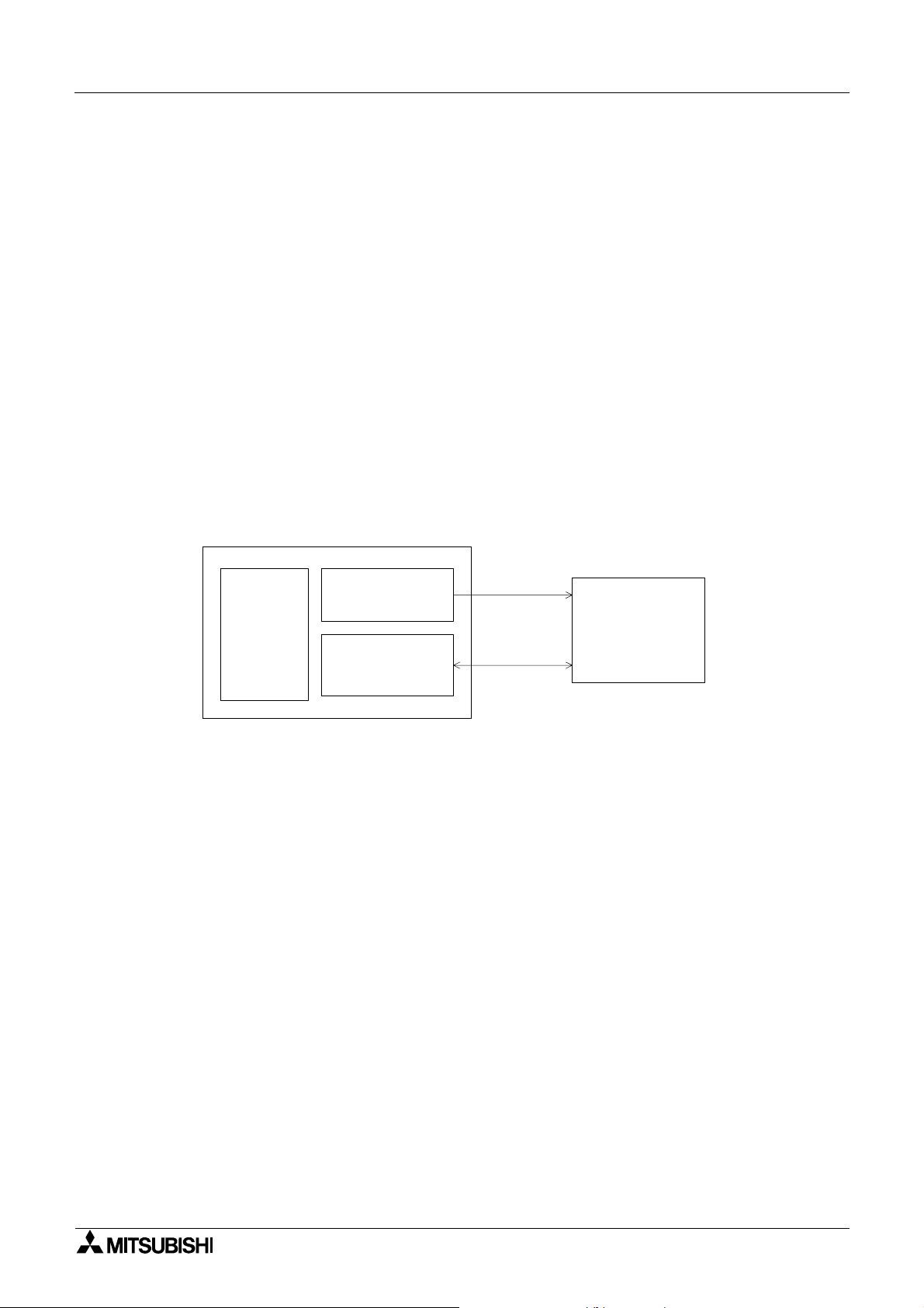
This section describes the product and system configuration of the graphic operation terminal.
1.1 Outline
The graphic operation terminal (he reafter abbreviated to
GOT) is to be mounted on the face of a control panel or
operations panel, and connected to a programmable
controller (hereafter abb re viat ed to PLC (e xcept t he A0J2))
Various devices can be monitored and PLC data changed
through the screens of the GOT.
There are several display screens built-in to the GOT
which offer various functions. In addition user defined
screens can be created.
The user defined screens and the built-in screens (system
screens) have the following respective functions.
Introduction 1
PLC
Program
port
G O T m ain body
User screens
• Screen display function
The following functions can be assigned to each screen. Also the available screens can be
limited using the security function.
Both software packages, FX-PCS-DU/WIN-E, and SWoD5C-GOTRE-PACK ("o" indicates
a numeric not less than "1".) can be used to create user screens.
Display function
- Up to 500 user defined screens can be displayed. In screen creation, two or more
screens can be overlaid or changed over arbitrarily.
- Simple graphics such as straight lines, circles and rectangles can be displayed, along
with numerics and English, Japanese, Chinese and Korean text. Also bitmaps can be
imported and displayed as well as pre-defined screen components.
Monitor function
- Set values and current values of word devices in the PLC can be displayed in numerics
or bar graphs for monitoring.
- The specified range of the screen components can be displayed in reverse in
accordance with the ON/OFF status of bit devices in the PLC.
Data change function
- The numeric data being monitored can be changed.
Switch function
- By manipulating the operation keys in the GOT, bit devices in the PLC can be set to ON
and OFF.
The display panel face can be assigned as touch keys to offer switch functions.
1-1

Graphic Operation Terminal GOT-F900 Introduction 1
System screens
• Monitor function
List program (only in the FX Series)
- Programs can be read, written and monitored in the form of an instruction list program.
Buffer memory (only in the FX
and FX
2N
2NC
Series)
- The contents of buffer memories (BFMs) of special blocks can be read, written and
monitored.
Device monitor
- The ON/OFF status of each device, the set value and current value of each timer,
counter and data register in the PLC can be monitored and changed.
- Specified bit devices can be forced ON or OFF.
Unlike the monitor function described previously, screen data can be edited by inputting
a desired device No. from the keyboar d.
• Data sampling function
The current value of spe cified data re gisters are ac quired in a con stant cyc le or w hen the
trigger condition is satisfied.
- Sampling data can be displayed in the form of list or graph.
- Sampling data can be output to a printer in the form of list.
• Alarm function
Alarm messages can be assigned to up to 256 consecutive bit devices in the PLC. When a
bit device becomes ON, the assigned message is displayed (overlapped) on the user
screen.
In addition, a specified user screen can be displayed by setting a corresponding bit device
to ON.
- When a bit device becomes ON, a corresponding message is displayed on the user
screen. The message list can be also displayed.
- Up to 1,000 alarms (turning ON of bit devices) can be stored as the alarm history.
- The alarm frequency of each device can be stored as historical data.
- Alarm history can be output to a printer using the screen creation software.
• Other functions
Many other functions are built in.
- A real-time clock, current time and data can be set and displayed.
- The GOT can function as an interface to enable data communication between the PLC
and a personal computer in which the relay ladder creation software is operating. At this
time, the GOT screen can also be displayed.
- The screen contrast and the buzzer sound volume can be adjusted.
1-2
Graphic Operation Terminal GOT-F900 Introduction 1
1.2 Format of manual
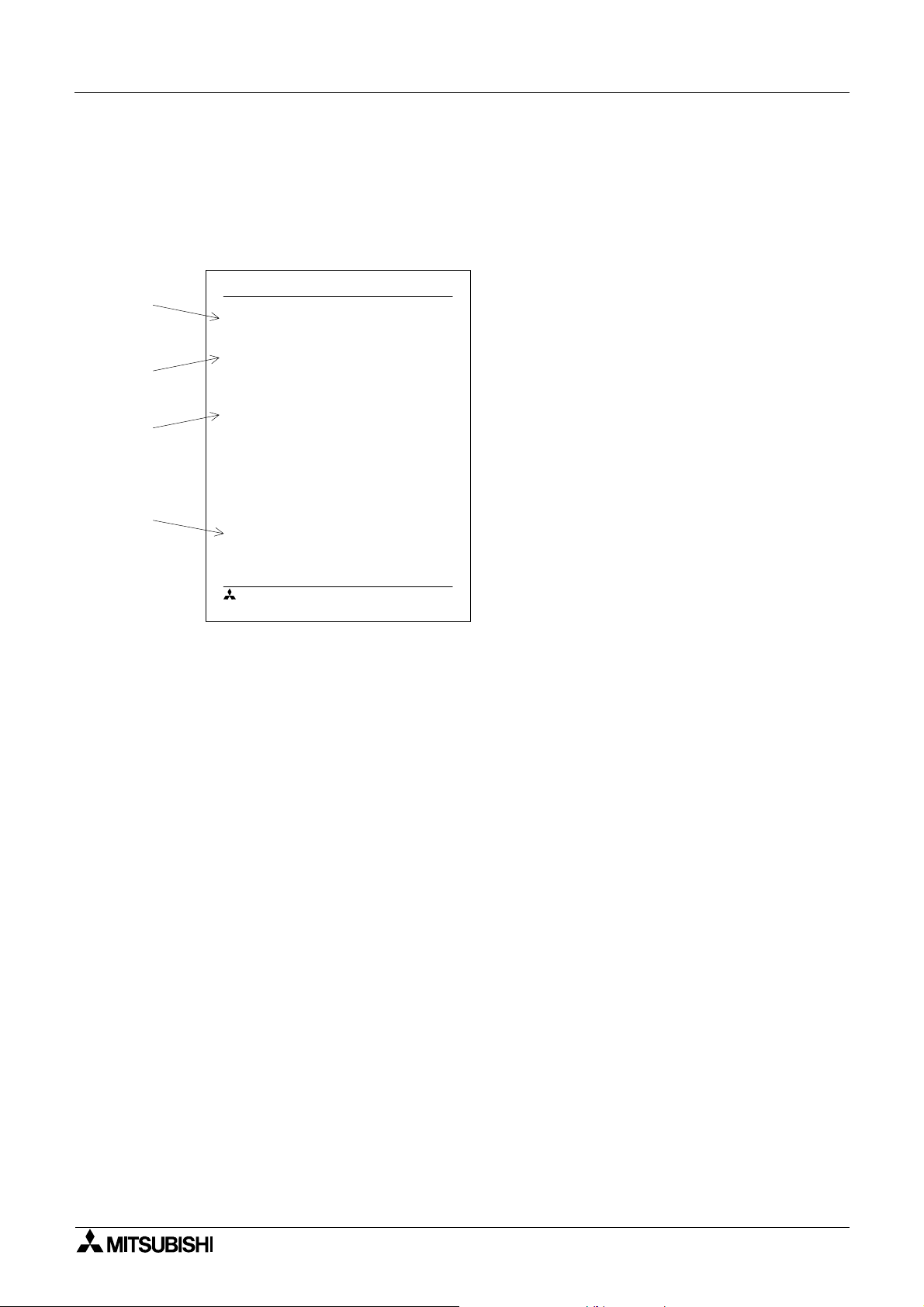
1.2.1 Contents described in manual
This manual is described in the foll owing format. Use each element of the format for index.
Example:
Graphic Operation Terminal F940G OT
a)
b)
c)
d)
2. Startup
2.1 Startup procedure
2.1.1 GOT setup
n
Important point
MITSUBISHI
1.2.2 Abbreviations used in text
The following terms may be abbreviated in the text.
Startup 2
a) Section title
Sections 1 to 17 describe operations.
Sections 18 to 21 describe the contents
required to create screens.
b) Title
The title explains the contents of each
paragraph.
c) Sub title
d) Important point
Ter ms used in the text are explained and
supplemented.
2-1
1) MELSEC FX series, A Series, QnA series, Q series unit and programmable controllers of
other companies may be abbreviated as "programmable controller" or "PLC".
2) The software kit to create display screens FX-PCS-DU/WIN-E or GT Designer may be
abbreviated as "screen creation software".
3) A general-purpose computer may be abbreviated as "PC".
4) A floppy disk may be abbreviat ed as "FD". A f loppy disk drive ma y be ab b reviated as "FDD".
5) The graphic operation terminal GOT-F900 Series may be abbreviated as "GOT".
6) Devices in side the PLC may be abbreviate d as "X" (i nput ), "Y" (ou tput), "M" (aux ili ary rela y),
"S" (state), "T" (timer), "C" (counter) and "D" (data register). Output contacts of X,Y, M, S, T
and C are called "bit devices". T, C and D are called "word devices". All of them may be
called "devices".
1-3
Graphic Operation Terminal GOT-F900 Introduction 1
1.3 Expressions and basic functions of operation keys
The operation keys are expressed as follows in the text.
The example of the screen display and key operation are described as an example of
F940GOT when there is no description.
1.3.1 Expressions of operation keys
1) Touch keys on the screen which are actuated when being touched by fingers are enclosed
with a frame.
USER SCREEN MODE,PROGRAM LIST
2) Cursor control keys to be pressed may be expressed as follows.
, ,
3) When a same key is pressed several times or a same operation is repeated, the following
expression may be used.
MORE,
4) When an arbitrary numeric within the range of 0 to 9 is to be entered, the following
expression may be used.
0 to 9
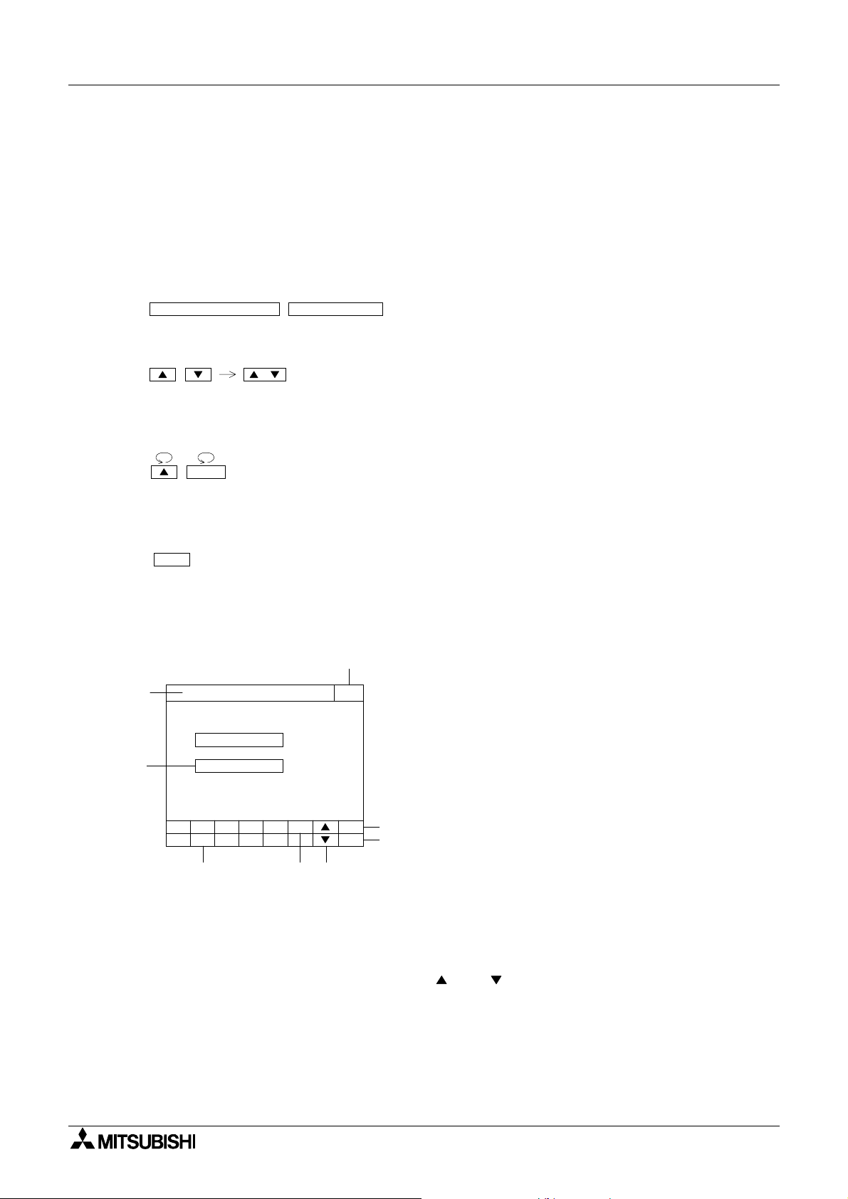
1.3.2 Basic operations
The common operations in the GOT are shown below.
a)
h)
[ SET CONDITION ] END
SAMPLE COND.
START COND.
END COND.
506
789- CLR
1234
e) f) g)
b)
ENT
a) Function display
The selected mode or function is displayed here.
b) END key
This key terminates the displayed function, and
returns to the previous screen.
c) CLR (clear ) key
This key cancels the input of characters and
numeri cs.
c)
d)
d) ENT (enter) key
This key determines the input of alphabets and
numeri cs.
e) Ten-key pad
This pad allows to enter numerics .
f) - (minus) key
g) and (cursor control) keys
h) SET key
When this key is pressed after a character or
numeric has been entered, the keyboard is
displayed.
1-4
Graphic Operation Terminal GOT-F900 Introduction 1
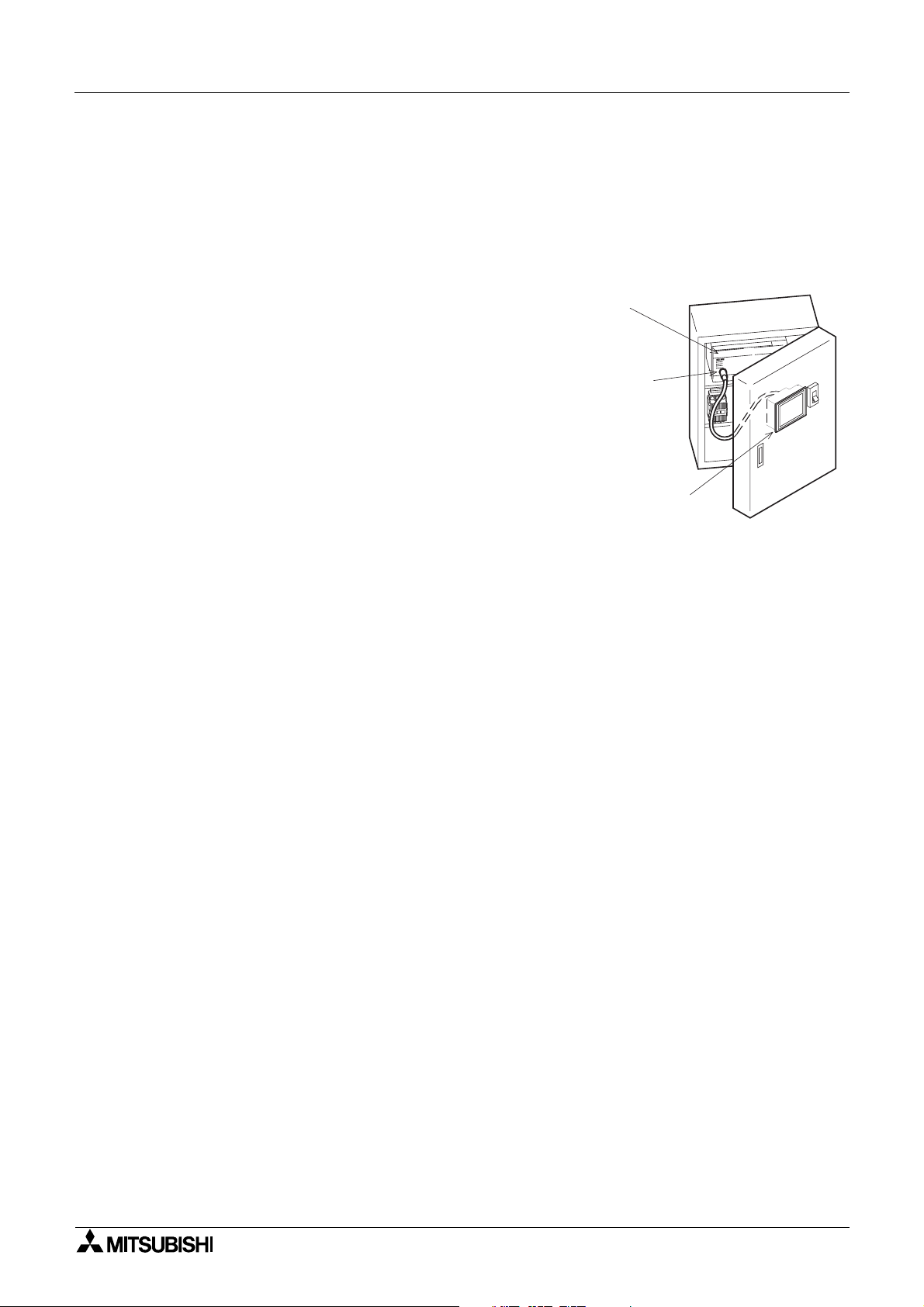
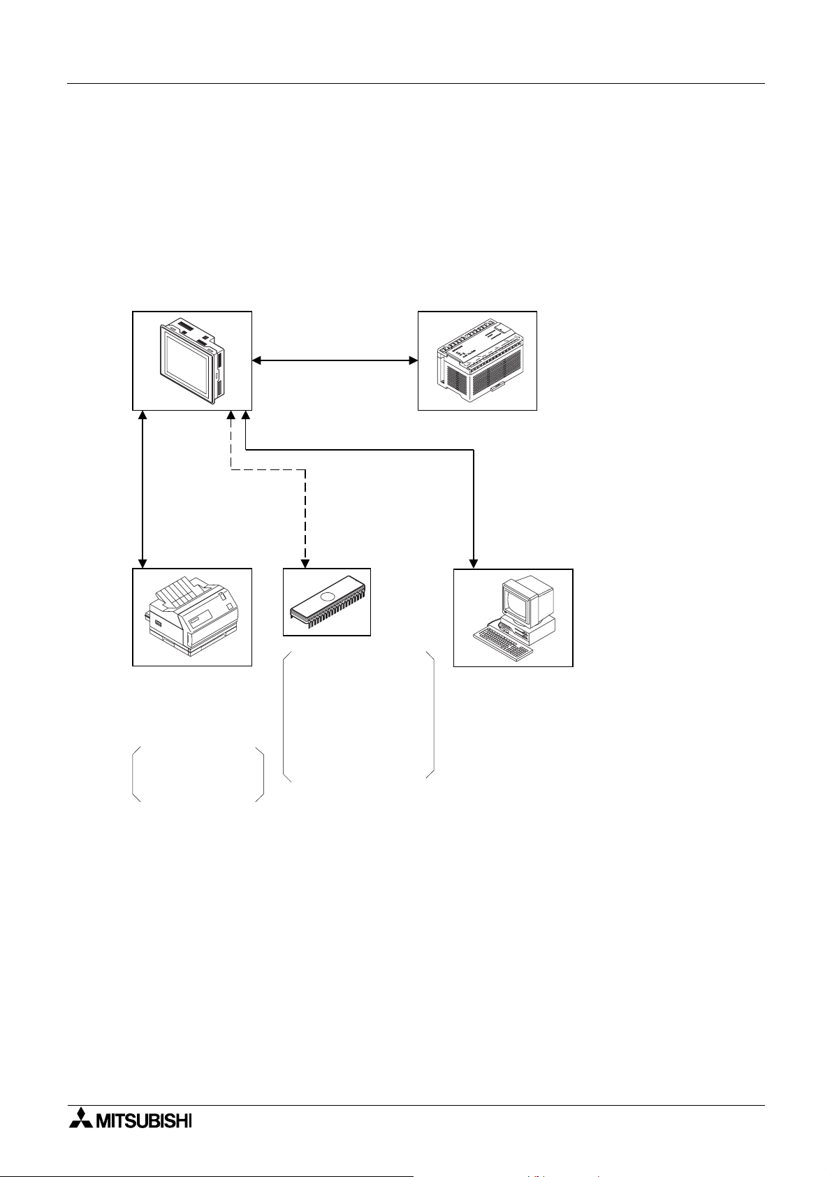
1.4 System configuration
The method of connecting the GOT to PLC and peripheral devices is described below.
1.4.1 Connection of peripheral units of GOT
The figure below shows the system configuration required to use the GOT with peripheral
devices.
F930GOT, F940GOT,
F943GOT and F940WGOT
graphic operation terminals
RS-422 or RS-232C
communication.
PLC
Data transfer
cable
F2-232CAB-1
(3m)
RS-232C communication.
·Printer
Bar code reader
<General-purpose printers>
ESC/P
Printer equipped with
RS-232C interface
Prints out sampling data,
alarm history, alarm
message and screen
hard copy
RS-232C communication.
The ROM is attached to
F9GT-40UMB and inserted
into the connector on the
back of the GOT.
(F940GOT and F943GOT
only)
·EPROM memory
User screens can be stored
using a general-purpose
ROM writer.
(FX-EPROM-4M)
FX-PCS-DU/WIN-E is used
to put screen data in the form
of ROM chips.
(In the case of GT Designer,
data cannot be saved on to a
ROM chip.)
·Data transfer cable FX-232CAB-1 (3 m)
(when the RS-232C port in the PC is 9-pin
type)
·Data transfer cable FX-232CAB-2 (3m)
(when the RS-232C port in the PC is half pitch, 14-pin type)
·Data transfer cable F2-232CAB-1 (3m)
(when the RS-232C port in the PC is 25-pin
type)
·General-purpose personal computer
(screen creation software)
FX-PCS-DU/WIN-E or GT Designer
·For the screen creation software
versions corresponding to each GOT, refer
to Section 1.7.
• When the GOT is CPU-connected to a PLC and a general purpose PC is used as a
program edit tool for the PLC, the 2-port interface function of the GOT can be used.
(In the case of connection using a communication unit of QnA Series or Q Series, the 2-port
interface function can be used when the setting of the GOT is fo r CPU connection.)
When using the GOT and peripheral devices dedicated to sequence program edit (such as
FX-20P and A6GPP that performs RS-422 communication) for one PLC, connect the GOT
to an extension communication board or extension communication adapter of FX Series, a
computer link unit of A Series or a communication unit of QnA Series or Q Series.
(The FX-2PIF type 2-port interface is not compatible with the PLCs of Q Series and QnA
Series or with PLCs or microcomputer boards manufactured by other companies.)
When connected to a PLC or microcomputer board manufactured by other companies, the
2-port interface function of the GOT cannot be used.
1-5
Graphic Operation Terminal GOT-F900 Introduction 1
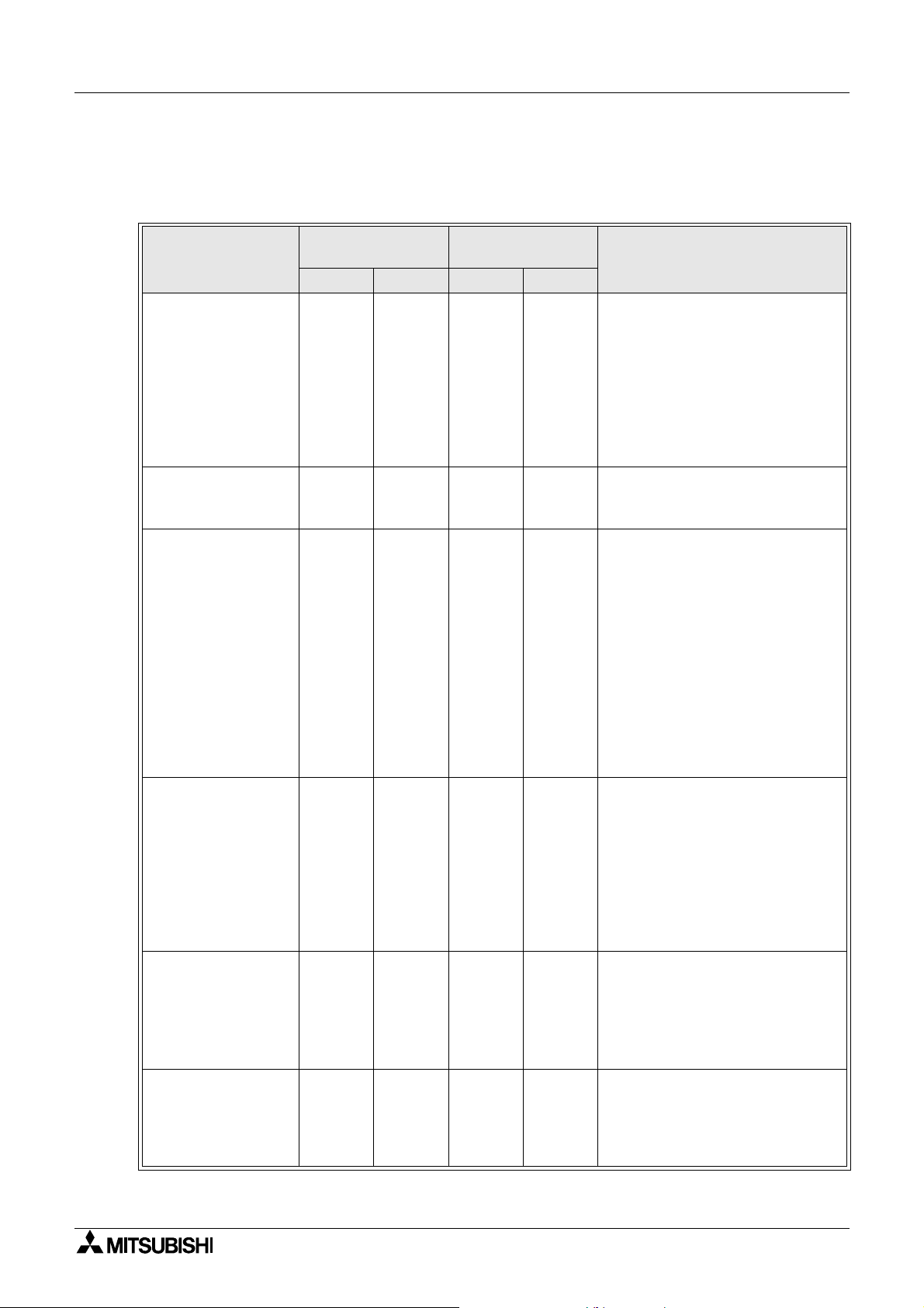
1.5 Connectable PLC
Setting of the PLC to be connected is made according to "PLC TYPE" in "Operation
environment setting (see Section 7)".
Connectable PLC
MELSEC FX
FX
, FX0, FX0S,
2C
FX
, FX0N, FX1N,
1S
FX
and FX
2N
, FX2,
1
2NC
Series manufactured
by Mitsubishi Erectric
MELSEC A Series
manufactured by
Mitsubishi Erectric
MELSEC QnA Series
manufactured by
Mitsubishi Erectric
MELSEC Q Series
manufactured by
Mitsubishi Erectric
MELSEC FX-10GM,
FX-20GM, E-20GM,
FX
-10GM, FX2N-
2N
20GM positioning
units
Motion controllers
A171SCPU-S3,
A171SHCPU,
A172SHCPU and
A272UHCPU
Direct connection
to CPU
Computer link
Upper link
RS-232C RS-422 RS-232C RS-422
¡¡
✕
✕
¡
✕
✕
¡¡¡
¡¡¡
✕
¡
¡
✕✕
¡¡
✕✕
✕✕
Remarks
For connection to FX
and FX1N
1S
Series, the following versions
should be used.
F930GOT, V2.10 or later should be
used.
F940GOT and F943GOT, V4.00 or
later should be used.
F940WGOT, any version may be
used.
Any version may be used.
When a communication unit is
used, settings for direct connection
to CPU should be made.
F930GOT, V2.00 or later should be
used.
F940GOT and F943GOT, V3.00 or
later should be used. (When a
version is former than V3.00 and
computer link connection is made,
only setting for computer link for A
Series is available.)
F940WGOT, any version may be
used.
When a communication unit is
used, settings for direct connection
to CPU should be made.
F930GOT, V2.20 or later should be
used.
F940GOT and F943GOT, V4.10 or
later should be used.
F940WGOT, any version may be
used.
F930GOT, V4.10 or later should be
used.
F940GOT, V6.10 or later should be
used.
F940WGOT, V1.10 or later should
be used.
Any version may be used.
1-6
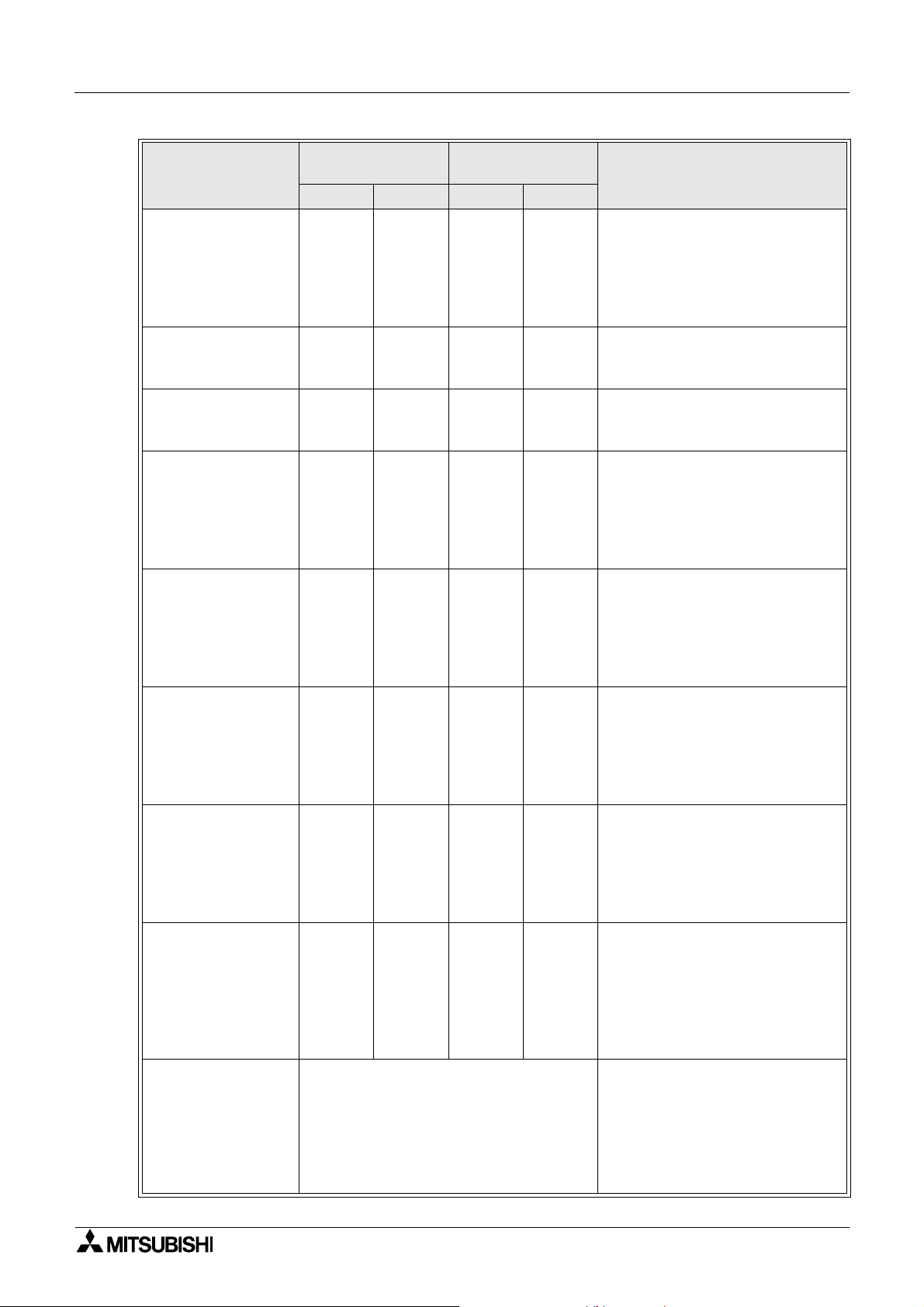
Graphic Operation Terminal GOT-F900 Introduction 1
Connectable PLC
Inverter FREQROLA500, E500 and
S500 Series
manufactured by
Mitsubishi Erectric
SYSMAC C Series
manufactured by
Omron Corp.
FLEX-PC N Series
manufactured by Fuji
Electric Co., Ltd.
FP Series FP0 and
FP2SH manufactured
by Matsushita
Electric Works
Machine controllers
CP9200SH, MP920
and MP930
manufactured by
Yasukawa Electric
Corp.
SLC500 Series
manufactured by
Allen-Bradley Co.,
Inc.
MicroLogix 1000/
1200/1500 Series
manufactured by
Allen-Bradley Co.,
Inc.
S7-300/400 Series
manufactured by
Siemens AG
Microcomputer board
Direct connection
to CPU
Computer link
Upper link
RS-232C RS-422 RS-232C RS-422
✕
✕✕
✕✕
¡
¡¡
¡
¡
¡
¡
✕✕
¡¡
¡¡
✕✕✕
✕✕
✕✕✕
✕✕✕
✕✕✕
Select a communication procedure
according to the GOT (RS-232C/RS-422).
Remarks
F930GOT, V4.10 or later should be
used.
F940GOT, V6.10 or later should be
used.
F940WGOT, V1.10 or later should
be used.
Any version may be used.
Any version may be used.
F930GOT, V4.10 or later should be
used.
F940GOT and F943GOT, V6.10 or
later should be used.
F940WGOT, V1.10 or later should
be used.
F930GOT, V3.00 or later should be
used.
F940GOT and F943GOT, V5.00 or
later should be used.
F940WGOT, any version may be
used.
F930GOT, V2.00 or later should be
used.
F940GOT and F943GOT, V5.00 or
later should be used.
F940WGOT, any version may be
used.
F930GOT, V4.00 or later should be
used.
F940GOT and F943GOT, V5.00 or
later should be used.
F940WGOT, any version may be
used.
HMI Adapter is necessary.
F930GOT, V3.00 or later should be
used.
F940GOT and F943GOT, V5.00 or
later should be used.
F940WGOT, any version may be
used.
When connecting two or more units
F930GOT, V3.00 or later should be
used.
F940GOT and F943GOT, V5.00 or
later should be used.
F940WGOT, any version may be
used.
1-7

Graphic Operation Terminal GOT-F900 Introduction 1
• In the case of F943GOT, connection to a PLC is limited to RS-232C communication.
The types connectable through RS-422 communication shown in the table above are not
applicable.
• For the method of wiring to a PLC, refer to "GOT-F900 SERIES HARDWARE MANUAL.
1-8
Graphic Operation Terminal GOT-F900 Introduction 1
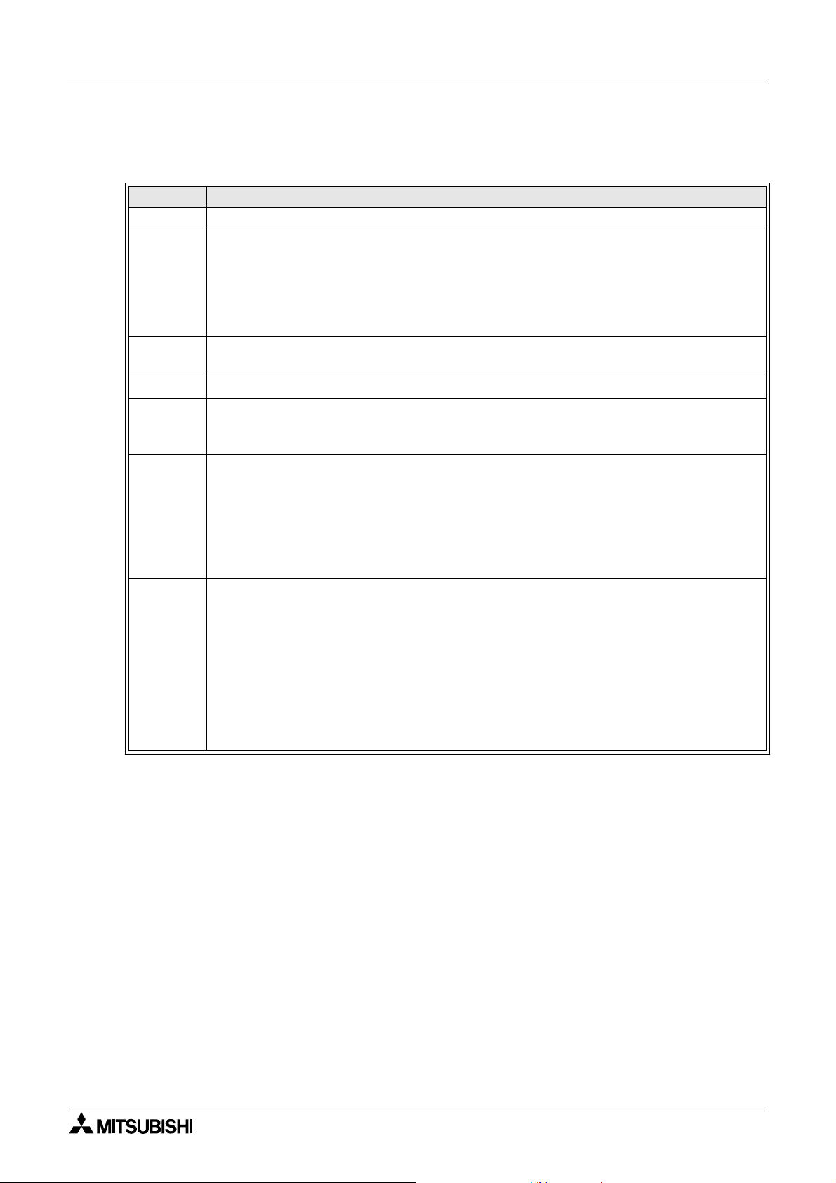
1.6 GOT version upgrade history
F930GOT
Version Description
V1.00 • First version
• Addition of function, connecting to QnA Series PLC
• Addition of function, bar code connection
V2.00
V2.10
V2.20 • Addition of function, connecting to Q Series PLC
V3.00
V4.00
V4.20
• Addition of function, observe status
• Touch key and lamp graphic extension
• Compatible with SLC500 Series manufactured by Allen-Bradley Co., Inc.
• Addition of rectangle and circle daubing pattern
• Addition of function, connecting to two or more units for microcomputer board
connection
• Addition of function, connecting to S7-300/400 Series manufactured by Siemens AG
• Addition of function, connecting to machine controller manufactured by Yasukawa
Electric Corp.
• Addition of function, connecting to MicroLogix 1000/1200/1500 Series manufactured
by Allen-Bradley Co., Inc.
• Addition of function, connecting to CS1 Series (CS1G/H-CPU¨¨-V1) manufactured
by Omron Corp.
(Connection condition: Link connection)
• Addition of function, entering numeric values including decimal points
• Addition of security function (screen protection)
• Addition of function, connecting to MELSEC positioning units FX-10/20GM, FX
20GM, E-20GM
• Addition of function, connecting to inverter FREQROL-A500, E500 and S500 Series
• Addition of function, connecting to FP0 and FP2SH Series manufactured by
Matsushita Electric Works
• Addition of function, connecting to S7-200 Series manufactured by Siemens AG
• Addition of function, displaying alarms in alarm list in order of occurrence
• Addition of function, high-definition font display
• Addition of function, "6dots × 8dots" font display
• Coping with customizing of key window
2N
-10/
1-9
Graphic Operation Terminal GOT-F900 Introduction 1
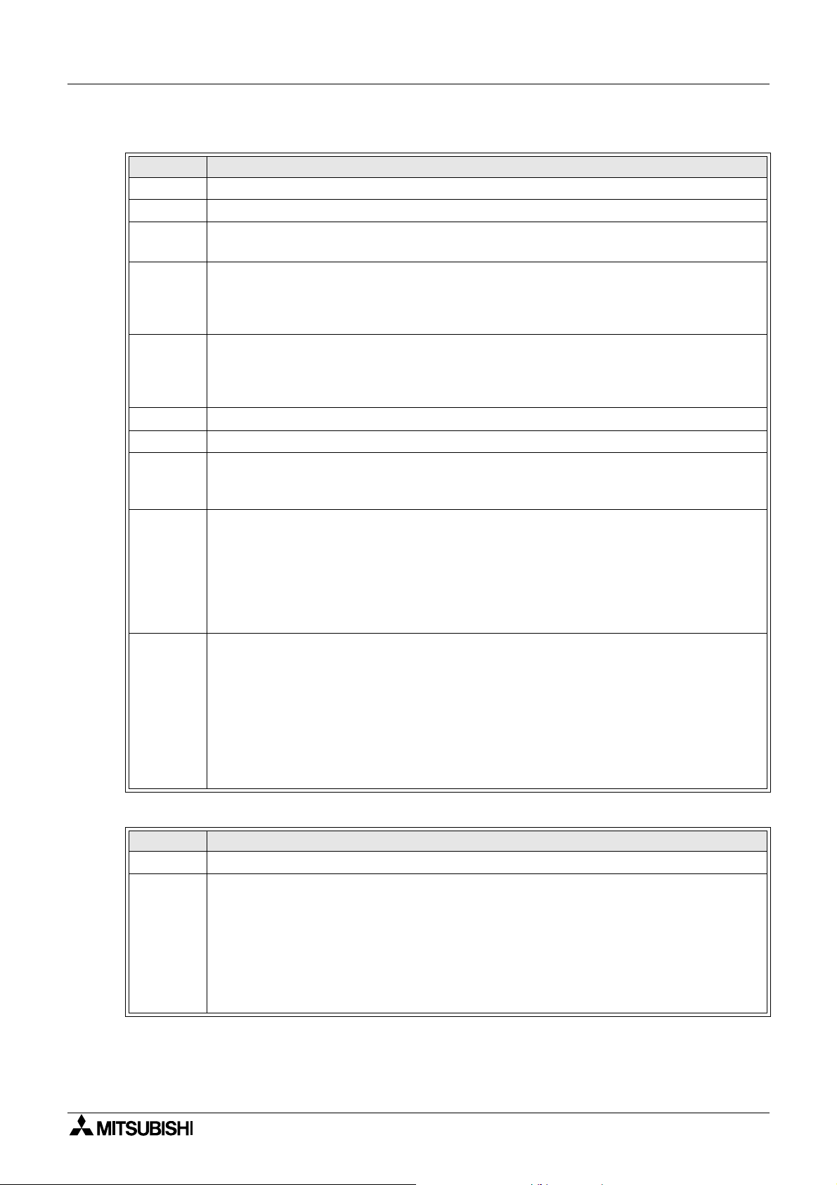
F940GOT and F943GOT (including handy GOT)
Version Description
V1.00 • First version
V1.10 • Compatible with QnA Series (A Series mode)
V2.00
V3.00
V3.10
V4.00 • Addition of function, connecting to FX
V4.10 • Addition of function, connecting to Q Series PLC
V5.00
V6.00
V6.20
• Compatible with SLC500 Series manufactured by Allen-Bradley Co., Inc.
• Addition of function of bar code connection
• Addition of function, connecting to QnA Series PLC
• Addition of hard-copy function
• Addition of setting of key window initial display position
• Addition of key code for alarm history
• Addition of observe status function
• Compatible with customizing of key window
• Touch key and lamp graphic extension
• Addition of rectangle and circle daubing pattern
and FX1N Series PLC
1S
• Addition of function, connecting to S7-300/400 Series manufactured by Siemens AG
• Addition of function, connecting to machine controller manufactured by Yasukawa
Electric Corp.
• Addition of function, connecting to MicroLogix 1000/1200/1500 Series manufactured
by Allen-Bradley Co., Inc.
• Addition of function, connecting to CS1 Series (CS1G/H-CPU¨¨-V1) manufactured
by Omron Corp.
(Connection condition: Link connection)
• Addition of function, entering numeric values including decimal points
• Addition of security function (screen protection)
• Addition of function, connecting to MELSEC positioning units FX-10/20GM, FX
2N
-10/
20GM, E-20GM
• Addition of function, connecting to inverter FREQROL-A500, E500 and S500 Series
• Addition of function, connecting to FP0 and FP2SH Series manufactured by
Matsushita Electric Works
• Addition of function, connecting to S7-200 Series manufactured by Siemens AG
• Addition of function, displaying alarms in alarm list in order of occurrence
• Addition of function, high-definition font display
• Addition of function, "6dots × 8dots" font display
F940WGOT
Version Description
V1.00 • First version
• Addition of function, connecting to MELSEC positioning units FX-10/20GM, FX
20GM, E-20GM
• Addition of function, connecting to inverter FREQROL-A500, E500 and S500 Series
V1.10
• Addition of function, connecting to FP0 and FP2SH Series manufactured by
Matsushita Electric Works
• Addition of function, displaying alarms in alarm list in order of occurrence
• Addition of function, high-definition font display
• Addition of function, "6dots × 8dots" font display
1-10
2N
-10/
Graphic Operation Terminal GOT-F900 Introduction 1
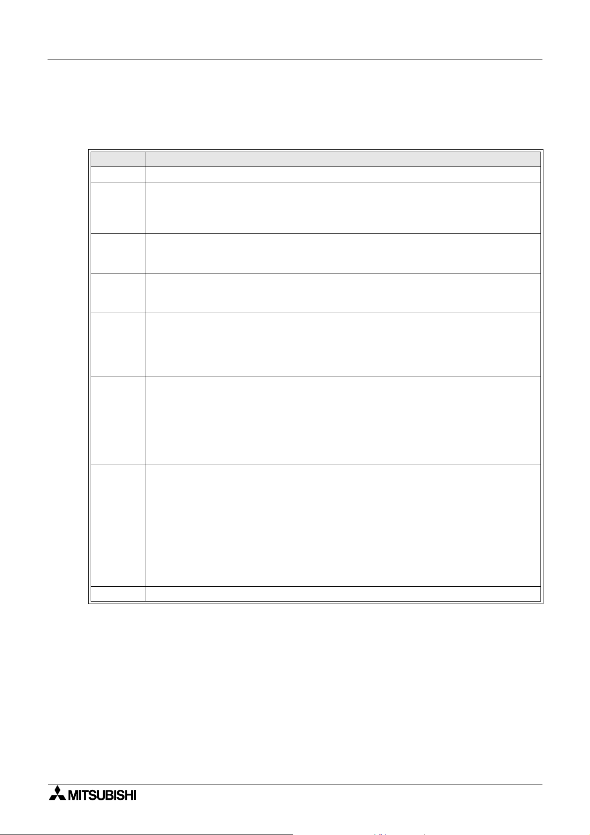
1.7 Screen creation software version upgrade history
The following software is used to create display screens.
FX-PCS-DU/WIN-E
Version Description
V1.00 • First version (not compatible with F900 Series GOT)
• Addition of function, programming F940GOT
V2.00
V2.10
V2.20
V2.30
V2.41
V2.50
V2.52 • Addition of function of connecting to S7-200 Series manufactured by Siemens AG
• Addition of setting, display of line graph (batch) object and outer frame
• Addition of function, programming ET-940BH (-L) display unit
• Addition of key code for alarm history
• Compatible with label color inversion of lamp (label) and touch key on black-and-white
liquid crystal display unit
• Addition of function, programming handy display unit (F940GOT-SBD-H/LBD-H)
• Addition of function, programming F930GOT display unit
• Improving of graphic size (320 × 240 dots) registered in image library
• Addition of function, connecting to bar code reader
• Addition of function, connecting to QnA Series PLC
• Addition of function, connecting to SLC500 Series manufactured by Allen-Bradley Co.,
Inc.
• Addition of function, hard-copy setting on F940GOT display screen
• Addition of graphic type to touch key and lamp (label) object
• Addition of hatching pattern of rectangle and circle object
• Addition of line type, straight line and rectangle object
• Compatible with European font display
• Addition of function, connecting to Q Series PLC
• Addition of function, connecting to S7-300/400 Series manufactured by Siemens AG
• Addition of alarm list and alarm history object
• Addition of display, alarm mode flow
• Addition of function, programming F940WGOT displayunit.
• Addition of PLC connectable to GOT
MELSEC positioning unit FX-10/20GM, FX
E500, S500 Series
Extension of support device of SLC500 Series manufactured by Allen-Bradley Co., Inc.
MicroLogix Series manufactured by Allen-Bradley Co., Inc.
• Addition of setting, observe status function
• Compatible with high-definition font display
• Compatible with "6 × 8 dots" font display
• Addition of GOT-F900 internal device (GB, GD)
-10/20GM, E-20GM, FREQROL A500,
2N
1-11
Graphic Operation Terminal GOT-F900 Introduction 1
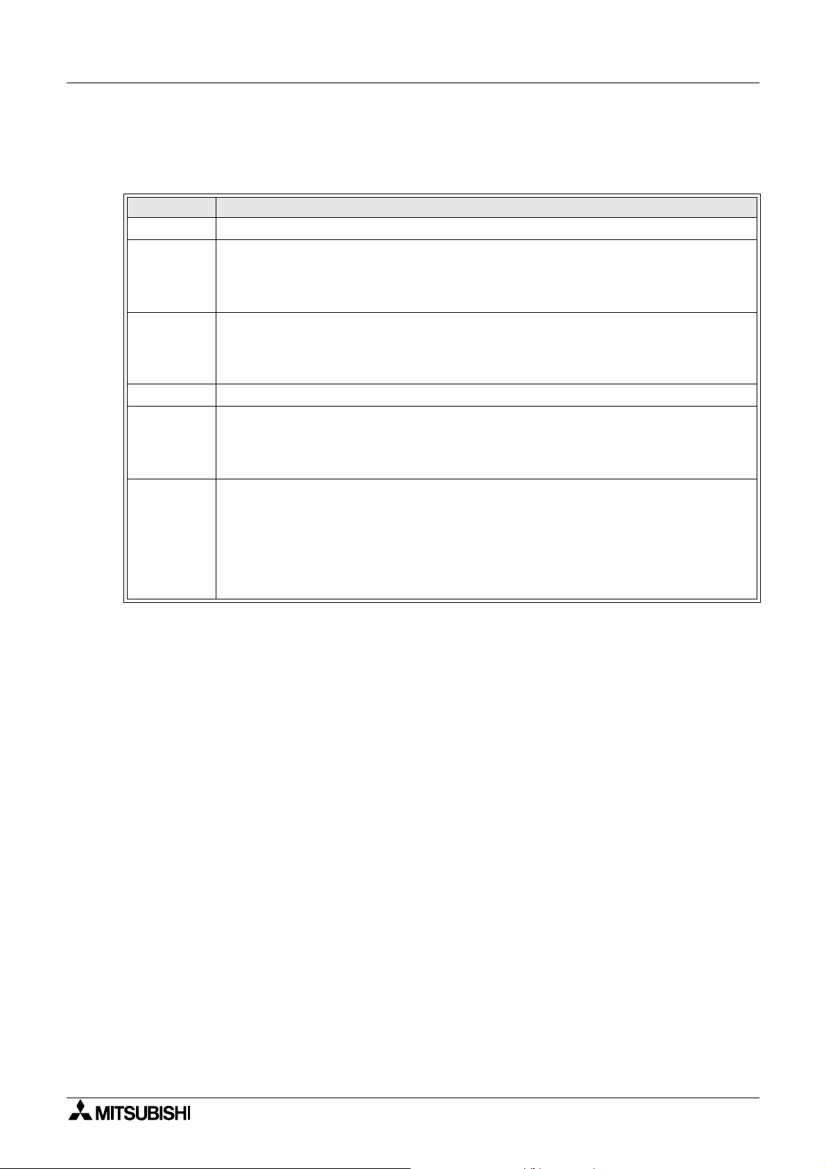
GT Designer (Main items relating to F900 Series GOT)
SW
¨
: Abbreviation of SW¨D5C-GOTR-PACKE
(A), (B)... : Abbreviation of screen creation software package version name
Version Description
SW0D5C(A) • First version (not compatible with F900 Series GOT)
•Usable for F940GOT
SW1D5C(E)
SW1D5C(H)
SW2D5C(A) • Addition of hard-copy function
SW5D5C(F)
V5.05F
SW5D5C(K)
V5.09K
(Usable for F940GOT whose main unit version is V1.10 or later)
• Addition of function, connecting to C Series manufactured by Omron Corp.
• Addition of function, connecting to microcomputer
•Usable for F930GOT
• Addition of function, connecting to bar code reader
• Addition of function, connecting to SLC500 Series manufactured by Allen-Bradley
Co., Inc.
• Compatible with connecting to MicroLogix 1000/1200/1500 Series manufactured by
Allen-Bradley Co., Inc.
• Compatible with connecting to CS1 Series (CS1G/H-CPU¨¨-V1) manufactured by
Omron Corp.
• Compatible with connecting to MELSEC positioning units FX-10/ 20GM, FX
20GM and E-20GM
• Compatible with connecting to FREQROL A500, E500 and S500 Series
• Compatible with connecting to FP Series manufactured by Matsushita Electric
Works
• Compatible with high-definition font display
• Compatible with "6 × 8 dots" font display
2N
-10/
• The items shown above are main items relating to F900 Series GOT.
For further details abou t the version upgrade of each pie ce of software, refer to the result
operation manual (operating manual).
* Usable fer F940WGOT
1-12
Graphic Operation Terminal GOT-F900 Introduction 1
1.8 Preservation of screen data and backup
The undermentioned data is stored in RAM of GOT or the flash memory.
RAM area: Data is backed up with the built in battery.
1) Content set by system setting requirements of GOT main unit.
2) Alarm history
3) Sampling collection data
4) Operating time
Flash memory area: Battery is unnecessary.
1) Data made with screen creation software.
Screen data, system requirement settings, alar m element settings, and sampling element
settings.
GOT
Create screen software
RAM
➀
RAM ➁ to
Flash memory
➃
➁
Read only
Personal computer
Transfer
• Transfer between the screen creation software and GOT is done between RAM area ➁, ➂,
➃
and the flash memory.
Neither “RAM area” nor “Time now” is read to the personal computer.
• The systems requirements can be set with the GOT main unit (a default content is stored in
RAM ➀) or the screen creation software (a set content is preserved in flash memory ➀).
The content set later is given priority.
User set data may be last if the back up battery power runsout. In thi s situation , it ma y not be
possible to communicate with the programmable controller.
If possible set the system requirements in the screen creation software.
1-13

Graphic Operation Terminal GOT-F900 Introduction 1
MEMO
1-14

Graphic Operation Terminal GOT-F900
2. Specifications
For the power supply specifications, refer to "GOT-F900 SERIES HARD WARE MANUAL".
2.1 General specifications
Item Specifications
Use: 0 to 50°C (32 to 122°F) (0 to 40°C when using an extension interface or for handy
GOT)
Temperature
Humidity
Vibration
resistance
Shock
resistance
Noise
resistance
Withstand
voltage
Insulation
resistance
Grounding
Working
atmosphere
Protective
structure
Storage: -20 to 60°C (-4 to 140°F)
In the case of F940WGOT, ambient temperature should be 0 to 50°C for vertical
mounting; 0 to 40°C for horizontal mounting.
35 to 85%RH (non-condensing) (35 to 80%RH for F930GOT)
Conforms to
IEC 1131-2
Conforms to IEC 1131-2 (147m/s
1,000Vp-p, 1µs, 30 to 100Hz, tested by noise simulator.
500V AC for 1 min
5MΩ or more at 500V DC
Class D (100Ω or less)
No corrosive gas and no significant dust
Equivalent to IP65F (Handy GOT: IP54)
With
intermittent
vibration
With
continuous
vibration
Frequency Acce lerat ion Amplitude
10 to 57Hz
57 to 150Hz 9.8m/s
10 to 57Hz
57 to 150Hz 4.9m/s
2
, 3 times in each direction X, Y and Z)
2
2
0.075mm
0.035mm
Tested between power terminals and ground
Specifications 2
10 times in each
of X, Y and Z
directions
(for 80 minutes)
2-1

Graphic Operation Terminal GOT-F900 Specifications 2
2.2 Display section specifications
Specifications
Item
LCD type
Display
element
Screen
Life of liquid crystal
Back light
Key
Interface
Number of screens
User memory
Dot pitch
Horizontal
Vertical (mm)
Display color
Number of
keys used
Configuration
(Horizontal
Vertical)
RS-422
RS-232C
F930GOT-BWD
STN-type full dot matrix LCD
0.47 × 0.47 0.36 × 0.36
××××
Monochrome
(Blue/White)
"240 × 80 dots"
liquid crystal
Valid display
dimension: 117 × 42
mm (4”-type)
Approximately 50,000 hours (Ordinary temperature: 25°C/77°F, Ordinary
humidity)
Guaranteed term is 1 year.
Cold cathode
(life of 50,000 hours
or more at 25°C/
77°F)
Guaranteed term is 1 year.
Touch key Max. 50 keys/1 screen
"15 × 4" matrix
××××
configuration
In conformity with RS-422 standard, 1 channel and for PLC communication
(F943GOT has no RS-422 connector.)
In conformity with RS-232C standard, 1-channel and for
screen data transfer.
(F943GOT: In conformity with RS-232C standard, 2
channel and for screen data transfer and for PLC
communication)
User created screen: Max. 500 screens (Screen number: No.0 to No. 499)
System screen: 25 screens (Screen number: No.1001 to No. 1030)
Flash memory
256KB
F940GOT-LWD
F943GOT-LWD
Monochrome
(Black/White)
"320 × 240 dots" liquid crystal
Valid display dimension: 115 × 86
mm (6”-type)
Cold cathode
(life of 40,000 hours or more at
25°C/77°F)
"20 × 12" matrix configuration
Flash memory 512KB Flash memory 1MB
F940GOT-SWD
F943GOT-SWD
8 colors 256 colors
F940WGOT-TWD
TFT-type full dot
matrix LCD
0.324 × 0.375
"480 × 234 dots"
liquid crystal
Valid display
dimension: 155.5 ×
87.8 mm (7”-type)
Cold cathode
(life of 40,000 hours
or more at 25°C/
77°F)
"30 × 12" matrix
configuration (last
column composed of
14 dots)
In conformity with
RS-232C standard,
2-channel and for
screen data transfer
and for PLC
communication
*1
*1 In the case of F940WGOT, when used in the vertical position, characters name a ratio of
about 1: 1.16.
2-2
Graphic Operation Terminal GOT-F900
Outside dimensions 3
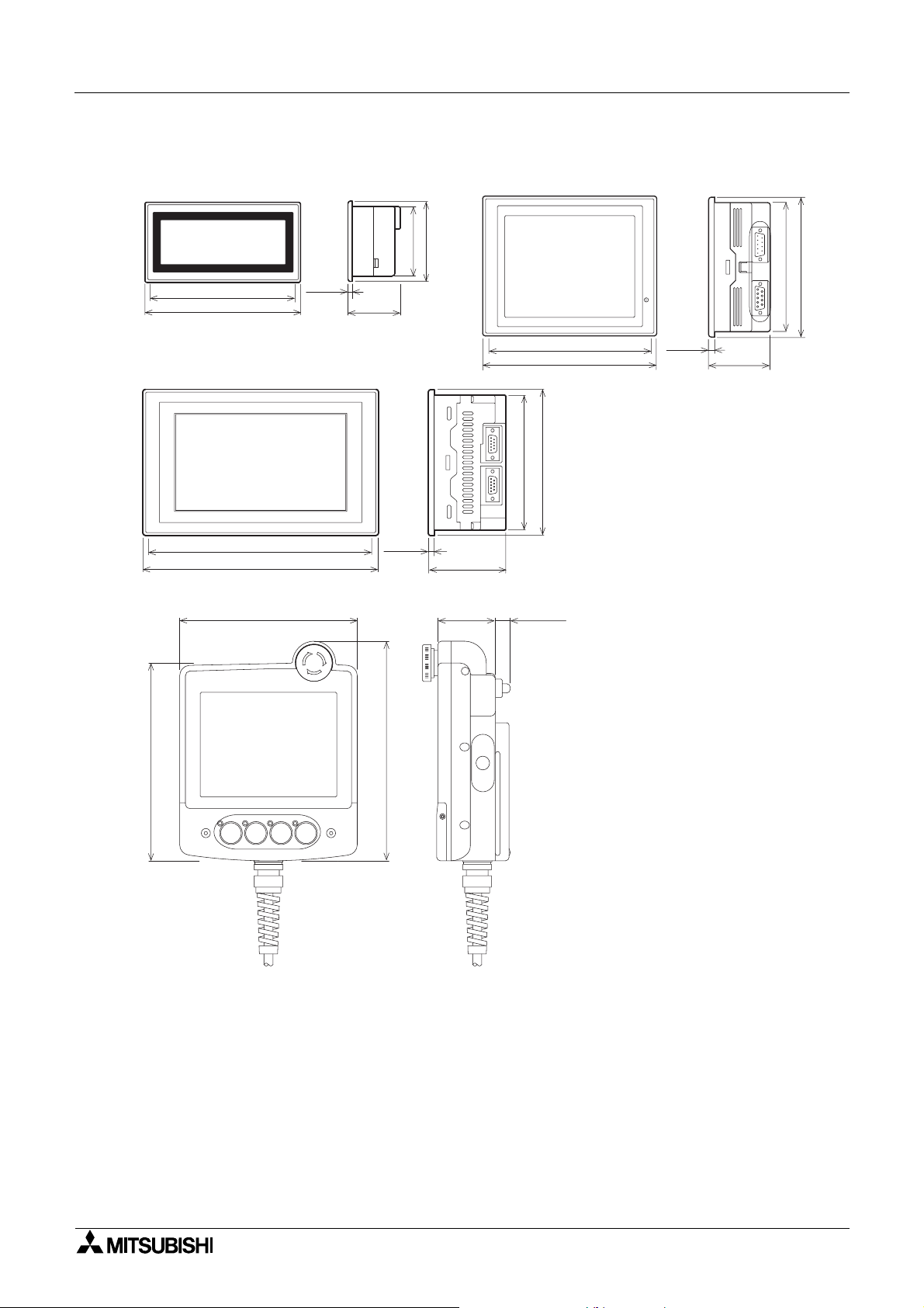
3.
Outside dimensions
F930GOT
136(5.35")
146(5.75")
F940WGOT
205(0.79")
215(8.46")
Handy GOT
156 (6.14")
5(0.20")
49(1.93")
65(2.56")
5(0.20")
75(2.95")
F940GOT,F943GOT
123(4.84")
133(5.24")
70.6(2.78")
50.5
(1.99")
13 (0.51")
152(5.98")
162(6.38")
RS232C RS422
130(5.12")
POWER
5(0.20")
57(2.24")
120(4.72")
)
)
"
172 (6.71
POW ER GRIP SW
"
191 (7.45
Dimensions: mm (inches)
MASS: F930GOT 0.3kg (0.66lbs)
F940GOT, F943GOT 1kg (2.2lbs)
F940WGOT 1kg(2.2lbs)
Handy GOT 0.79kg(1.74lbs)
Accessory: F930GOT, F940GOT, F943GOT, F940WGOT
- Mouting brackets.
- Tightning bolt (M3 (0.12”), 4bolts)
- packing seal (for dust and water resistance)
Handy GOT
- Sheets to change switch names
3-1

Graphic Operation Terminal GOT-F900 Outside dimensions 3
MEMO
3-2

POW ER
1)
<Example>
Front panel of F940GOT
2)
1)
Graphic Operation Terminal GOT-F900
4. Part names
4.1 Front panel
1) Display
- F930GOT
"240 × 80 dots" graphic display
Character string:30 characters × 5 lines
- F940GOT, F943GOT
"320 × 240 dots" graphic display
Character string:40 characters × 15 lines
- F940WGOT
"480 × 234 dots" graphic display
Character string:
60 characters × 14 lines / Horizontal display
29 characters × 30 lines / Vertical display
• Alphabetic characters and numeric characters can be enlarged by 1/2 to 4 times ver tically
and by 1 to 4 times horizontally.
Part names 4
4.2 Rear panel
2)
3)
1) Power terminal : Used to supply power to the GOT and for grounding.
2) Battery : Used to store sampling data, alarm history and current time.
3) Extension interf ace :Used to connect optional extension devices.
4) CN↔OP selector switch : Not used (F940GOT, F943GOT)
F930GOT
F940GOT
4)
F943GOT
2)
3)
24VDC
+
-
4)
2)
3)
24VDC
+
-
1)
1)
F940WGOT
Screen data is stored in the built-in flash memory, for which no
battery power is needed.
A F9GT-40UMB type data transfer adapter is connected to
transfer screen data stored in the EPROM.
4-1

Graphic Operation Terminal GOT-F900 Part names 4
4.3 Functions of connectors
A PLC and peripheral devices are connected to the following connectors of the GOT.
F930GOT F943GOT F940WGOTF940GOT
4)
1) 2)
2)
RS232C
1)
RS422
4)
RS232C
3)
RS232C
1) Port for PLC (RS-422 connector) D-sub, 9-pin, female
- Used for RS-422 connection to a PLC.
- Also used to connect two or more GOT units (RS-422 connection).
2) Port for PC (RS-232C connector) D-sub, 9-pin, male
- For connection to PC when transferring screen data created by the screen creation
software.
- Used for RS-232C connection to a PLC or microcomputer board.
- Also used to connect two or more GOT units (RS-232C connection) or for
communication with bar code reader or printer.
- 2-port interface function can be used. (A PC on which the ladder support software has
been started can be connected.)
3)
1)
3) Port for PLC (RS-232C connector) D-sub, 9-pin, male
- Used for RS-232C connection to a PLC or microcomputer board.
- Also used to connect two or more GOT units (RS-232C connection) or for
communication with a bar code reader or printer.
4) Port for PC (F940WGOT) (RS-232C connector) D-sub, 9-pin, male
- For connection to PC when transferring screen data created by the screen creation
software.
- Not used for connection to a PLC.
- When the GOT is connected to a PLC through Port 3) (RS-232C), it can be used to
connect two or more GOT units (RS-232C connec tion) or for communication with a bar
code reader or printer.
- 2-port interface function can be used. (A PC on which the ladder support software has
been started can be connected.)
4-2

Graphic Operation Terminal GOT-F900 Part names 4
• When connecting to a PLC through a computer link unit, the connector 1), 2) or 3) shoul d be
used.
• When two or more GOT units are connected, 2-system connection cannot be made.
It is not possible to connect two or more PLCs to one GOT.
PLC
PLC
PLC
GOT
GOTGOT GOT GOT
GOTGOT GOT
GOT
PLC
4-3

Graphic Operation Terminal GOT-F900 Part names 4
MEMO
4-4

Graphic Operation Terminal GOT-F900
5. Installation
5.1 Panel cut dimension
On the panel face, drill an installation hole of the dimension shown below.
W 137 (5.39”) 153 (6.02”) 206 (8.11”)
H 66 (2.60”) 121 (4.76”) 124 (4.88”)
Installation 5
Space for m etal fixture
H
H2
W
W2
Unit: mm (inches)
F930GO T F940GOT, F943GOT F940WGOT
- Make sure that the processing accuracy is 0 to +1 mm (0 to +0.04”).
- Make sure that the thickness of the installation panel is 5 mm or less.
5-1

Graphic Operation Terminal GOT-F900 Installation 5
Enlarged view
a)
b)
5.2 Installation
GOT-F900 units are designed as to be embedded in a panel. Instal l the GOT using the procedure
shown below. For the panel cut dimension, refer to the previous page.
1) Inserting the GOT into the panel face
Attach a packing seal to t he GOT. Inse r t the GOT from the
front of the panel face.
a) GOT
b) Packing seal
c) Installation hole
2) Fixing the GOT
Hang the hook of the metal fixture (offered as accessory) to
installation hook ho les in th e G OT. Tighten the bol t (offered as
accessory) securely in each position.
The GOT can be fixed in just four positions, at each cor ner.
However, to prevent dusts and water, fix the GOT in all six positions (excluding the F930GOT).
a) Metal fixture
b) Tightening bolt
* Make sure that the tightening torque for each bolt is 0.3 to 0.5
N•m.
b)
a)
c)
5-2

Graphic Operation Terminal GOT-F900 Installation 5
3) Inner dimension of the panel required for installation
When installing the GOT, take into consideration the inner dimension shown below.
a) PLC connection cable
b) Packing
F930GOT
85(3.35")
2 4 V D C
75(2.95")
9(0.35")
F940GOT, F943GOT
10(0.39")
23(0.91")
48.5(1.90")
6.5(0.25")
F940WGOT
23(0.91")
23(0.91")
136(5.35")
23(0.91")
152(5.98")
10(0.39")
23(0.91")
24V DC
-
9(0.35")
+
5(0.20") or less
130(5.12")
140(5.51")
6.5(0.25")
5(0.20")
23(0.91")
50(1.96")
34.5(1.35")
10(0.39")
24V DC
23(0.91")
23(0.91")
10(0.39")
143(5.63")
133(5.24")
34.5(1.35"")
5(0.20") or less205(8.07")
70.6(2.78")
5-3

Graphic Operation Terminal GOT-F900 Installation 5
MEMO
5-4

Graphic Operation Terminal GOT-F900
6. Function
6.1 Function list
The functions of the GOT are divided into 6 modes. The operator can use each function by
selecting the corresponding mode.
Function 6
Mode Function Outline of function
Screen
mode
HPP
mode
Character
display
Drawing • Straight lines, circles and rectangles are displayed.
Lamp display
Graphic display
Data display
Data change
function
Switch function
Screen
changeover
Data batch
transfer
Security
function
Program (list)
Parameter
BFM monitor
Device monitor
1)
Current value/
set value
change
2)
• Alphanumerics are displayed.
• The color of a specified area on the screen is inverted in
accordance with the ON/OFF status of the bit devices in
the PLC.
• Set values and current value s of the word devices in the
PLC can be displayed in the form of bar graph, line graph
or panel meter.
• Set values and current value s of the word devices in the
PLC can be displayed in the form of numeric.
• Current values and set values of the word devices are the
PLC can be changed.
• The ON/OFF status of bit devices in the PLC are
controlled.
• Controll can be in the format of momentary, alternate or
set/reset.
• The display screen can be changed over. The PLC or
touch key can be used to change over the display screen.
• Data saved in the GOT can be transferred to the PLC.
• Screens are displayed only when the proper password is
entered. (This function is available also in the system
screens.)
• Programs can be read/written/monitored in instruction list
program format.
• Parameters for the program capacity, memory latch range,
etc. can be read/written.
• Buffer memories (BFM) in special bl ocks for the FX
FX
Series can be monitored, and their set values
2NC
changed.
• The ON/OFF status of bit devices as well as current values
and set values of word devices can be monitored using
device Nos. and comment expression.
• Current values and set values of word devices can be
changed using device Nos. and comment expression.
2N
Reference
sections
9
18
20
7
/
10
6-1

Graphic Operation Terminal GOT-F900 Function 6
Mode Function Outline of function
Forced
HPP
mode
Sampling
mode
Alarm
mode
Test
mode
Other
mode
ON/OFF
3)
State monitor
PLC diagnosis • Error information in the PLC is read and displayed.
Condition
setting
Result display • The sampling result is displayed in the form of list or graph.
Data clear • The sampling data is cleared.
List (status
display)
History
Frequency • The number of events of each alarm is stored.
History clear • The alarm history is deleted.
Screen list • User screens are displayed in order of screen No.
Data file
Debug
operation
Communication
monitor
Time switch • A specified bit device is turned ON/OFF at specified time.
PC transfer
Printer output
Keyword
Environment
setting
• The bit devices in the PLC can be forced ON or OFF.
• State (S) Nos. in the ON status are automatically displayed
for monitoring (valid only when MELSEC FX Series is
connected).
• Conditions of up to four devices to be sampled, sampling
start/end time, etc. are set.
• The current alarms are displayed in the list in order of
occurrence.
• The alarm history is stored together with the event time, in
order of occurrence.
• The data used in the recipe function (data file transfer
function) is changed.
• The operations are checked to know whether key
operations, screen changeover, etc. have been correctly
performed on the displayed user screen.
• The status of communication with the connected PLC is
displayed.
• The screen data, the data sampling result and the alarm
history can be transferred between the GOT and the
screen creation software.
• The sampling result and the alarm history can be output to
a printer.
• The keyword (password) to protect programs in the PLC
can be registered.
• The initial setting can be specified for the system
language, connected PLC, serial transfer, title screen,
menu screen call, current time, backlight extinguishing
time, buzzer volume, LCD contrast, screen data clear, etc.
Reference
sections
10
11
12
13
14
Note : 1) to 3) in HPP mode are only valid for the FX series PLC.
6-2

Graphic Operation Terminal GOT-F900
7. Start up
This section describes the start up procedure from turning ON the power of the GOT to
selection of the mode.
This section also describes the important environment setting to be used in the GOT. Make
sure to read this section carefully.
Substitute from LCD CONTRAST to BRIGHTNESS and read in F940WGOT.
7.1 Start up procedure
This paragraph describes the star t up proce dure from tur ning O N the power of the GOT to
selection of the mode.
Start up 7
Perform wiring of the power
supply unit of the GOT.
Connect the PLC.
Turn on the
power without
pressing the
touch key.
The OPENING SCREEN is
displayed.
Turn on the
power while
pressing the
touch key.
The SET-UP
MODE screen
is displayed.
• Perform wiring of the power supply unit of the GOT.
• Connect the GOT and the PLC with an optional connection
cabl e.
• Turn on the power of the GOT. If the SET-UP screen is
required. When turning on the power press and hold the top
left hand corner of the GOT screen for more than 1 second.
• The OPENING SCREEN indicating the model name, the
version, etc. is displayed for the period set in "OPENING
SCREEN" in the SET-UP MODE screen.
• In the SET-UP MODE screen, set the required mode, the
connected PLC nam e, etc. The ope rating environment can
also be set in the OTHER MODE screen.
A user screen
is displayed.
When there is no screen data
7-1

Graphic Operation Terminal GOT-F900 Start up 7
The SELECT MODE screen is
displayed.
The selected mode screen i s
displayed.
• The SELECT MODE screen is displayed. Each menu
2
item on the screen functions as a touch key. When a
desired one is pressed, the corresponding mode is
selected.
* This SELECT MODE screen can be called also by
pressing a corner of the screen set in "MAIN MENU
CALL KEY" on the SET-UP MODE screen.
[ SELECT MODE ]
[ SELECT MODE ]
USER SCREEN MODE
HPP MODE
SAMPLING MODE
ALARM MODE
TEST MODE
OTHER MODE
• The selected mode screen is displayed.
END
2
The screen mode is selec ted.
• If the menu call key is not set in "MAIN MENU CALL
KEY" on the SET-UP MODE screen, the user screen
mode is selec te d .
7-2

Graphic Operation Terminal GOT-F900 Start up 7
7.2 Operation environment setting
The operation environment setting function performs initial setting important to operating the
GOT. The SET-UP MODE screen can be displayed by turning on the power while pressing and
holding the upper left cor ner o f the scre en in acco rdance w ith "2.1 S tar t up proc edure" or by
selecting SET-UP MODE on the OTHER MODE screen.
If an entry code has been registered usin g the security function (to protect screens), the
operation environment can be set on ly when an en tr y code input by the user is equivalent to
the registered entry code.
Turn on the power while pressing
and holding the upper left corner of
the screen.
Set the system language.
Press the END key.
The SET-UP MODE sc reen i s
displayed.
[SET UP MODE M ENU SCREEN]
[SET UP MODE]
a)
b)
c)
d)
e)
f)
g)
h)
i)
j)
LANGUAGE
PLC TYPE
SERIAL PORT (RS232C)
OPENNING SCREEN
MAIN MENU CALL
SET CLOCK
SET BACKLIGHT
BUZZER
LCD CONTRAST
CLEAR USER DATA
END
k)
l)
l)
The areas enclosed with broken lines function as touch keys. (Broken lines are not actually
displayed on the screen.)
a) LANGUAGE
Allows setting of the language displayed on the system screens such as Japanese or
English.
b) PLC TYPE
Allows setting of the connected PLC type.
c) SERIAL PORT
To be selected when a pr inter is connected to the GOT or when communication is
performed between the GOT and a micro computer board.
d) OPENING SCREEN
Allows setting of the duration in which the OPENING SCREEN is displayed immediately
after the power is turned ON.
e) MAIN MENU CALL KEY
Allows setting of the position of the touch key which calls the SELECT MODE screen
from the screen mode (in which a user screen is displayed).
f) SET CLOCK
Allows setting of the time used in the time switch and time display.
g) SET BACKLIGHT
Allows setting of the time the backlight is automatically turned OFF, after a period of
continuous idle time .
h) BUZZER
Allows setting of the buzzer sound issued when a key is pressed.
7-3

Graphic Operation Terminal GOT-F900 Start up 7
i) LCD CONTRAST (F940WGOT: BRIGHTNESS)
Allows setting of the LCD brightness.
j) CLEAR USER DATA
Deletes all user screen data.
k) END
Exits the SET-UP MODE screen.
l) Cursors
Change over the men u item on the SET-UP MODE screen.
Important point
nnnn
• When the items a) to e), g) and h) above are set in the GOT and screen data is transferred
from the screen creation software, the operation environment setting selected in the screen
creation software becomes valid. In such a case, set the operation environment in the GOT
again or align from the beginning the setting of the items a) to e), g) and h) above with that
in the screen creation software.
• An environmetal setting with the GOT main uni t is stored in RAM. (Refer to Paragraph 1.8)
7-4

Graphic Operation Terminal GOT-F900 Start up 7
Each setting screen is displayed as shown below. On each scre en, when the END key at the
upper right corner is pressed after setting is completed, the SET-UP MODE screen is
displayed.
[ LANGUAGE ]
[ LANGUAGE ]
SYSTEM LANGUAGE:
ENGLISH a)
CHARACTER SET:
JAPANESE
[ PLC TYPE ]
[ PLC TYPE ]
PLC TYPE:
CONNECTION:
DST STATION #:
GOT STATION #:
FX SERIES
CPU PORT(RS422)
* *
* *
END
END
• Set the language used on the system screens and the
user screens.
a) SYSTEM LANGUAGE (Initial: ENGLISH)
Allows setting of the language displayed on the
system screens and in error messages.
b) CHARACTER SET (Initial: JAPANESE)
b)
Allows setting of the language displayed on the user
screens. JAPANESE, CHINESE and KOREAN are
available. Only one language can be selected at a
time. English character set is always available.
a) PLC TYPE (Initial: FX SERIES)
Allows selection of any one among.
b) CONNECTION (Initial: CPU PORT(RS422))
a)
b)
c)
d)
Allows to set the connection metho d of the PLC
selected in a) above.
- CPU PORT:
The GOT is connected directly to the program port
in the PLC (RS-422 or RS-232C).
The FX Series, the A Series, a motion controller
and the N Series are availab le.
•Select the connected PLC type.
• The areas on the screen enclosed with
solid lines function as touch keys. Every
time a touch key is pressed, the
displayed contents are changed over.
- LINK PORT (RS422):
The GOT performs communication in accordance
with the RS-422 via a link unit.
The A Series, the C Series and the N Series are
available.
- LINK PORT (RS232C):
The GOT performs communication in accordance
with the RS-232C via a link unit.
The A Series, the C Series and the N Series are
available.
c) DST STATION # (Initial: 00)
Allocate station No. of PLC when connected as PLC
which uses station No..
d) GOT STATION # (Initial: 00)
Allocate station No. of GOT when connected as PLC
which uses station No..
7-5

Graphic Operation Terminal GOT-F900 Start up 7
[ SERIAL PORT ]
[ SERIAL PORT ]
SPEED:
DATA BIT:
STOP BIT:
PARITY:
HANDSHAKING:
PRINTER:
[ OPENNING SCREEN ]
[ OPENNING SCREEN ]
DISPLAY TIME 4 SEC.
5 6 7 8 9 - CLR
0 1 2 3 4 ENT
9600 bps
7 bit
1 bit
Even
XON/XOFF
DON'T USE
END
END
• Set the serial communication parameters for the
printer used to print out alarm messages and sampling
data. (Initial: Left screen)
• Make sure to set "PRINTER" to "USE" when a printer
is connected.
When it is set to "USE", the two-port interface
function is not available.
• When "LINK PORT (RS232C)" is selected on the PLC
TYPE screen, a printer cannot be connected.
• Set the duration in units of seconds in which the
OPENING SCREEN indicating the model name, the
version, etc. is displayed immediately after the power
is turned on. (Initial: 4sec)
• When the touch key "DISPLAY TIME" is pressed, the
time can be set using the ten-key pad displayed at the
bottom of the screen.
• Enter the desired display time using the ten-key pad
displayed at the bottom of the screen, then press the
ENT key to register the input time.
* If "DISPLAY TIME" is set to "0", the sc reen mode is
selected immediately after the power is turned on
and a user screen is displayed.
It is recommended to set 1 second or more for the
FX Series and 4 seconds or more for the A Series.
7-6

Graphic Operation Terminal GOT-F900 Start up 7
[ MAIN MENU CALL KEY ]
[ MAIN MENU CALL KEY ]
SELECT CALL KEY LOCATION
[ SET CLOCK ]
[ SET CLOCK ]
DATE 3 / 1 / 1999
TIME 10: 10: 10
END
END
• Set the menu call key which changes over the screen
mode (in which a user screen is displayed) to the
SELECT MODE screen.
The menu call key is mesh type, and 2 × 2 in size.
(Initial: On the left)
• One or two corners can be selected among the four
corners of the screen.
• When the menu call key is not set, only the screen
mode is availabl e. Any other mode is not available.
• If another touch key is assigned to the corners to
which the menu call key has been assigned, the menu
call function is disable d .
• Set the time used in the time switch, the sampling
mode and the alarm mode.
• When "DATE" or "TIME" is selected, date or time can
be entered using the ten-key pad displayed at the bottom of the screen. Enter the desired date or time, and
press the ENT key to register it.
5 6 7 8 9 - CLR
0 1 2 3 4 ENT
[ SET BACKLIGHT ]
[ SET BACKLIGHT ]
OFF TIME 10 MIN.
5 6 7 8 9 - CLR
0 1 2 3 4 ENT
END
• Set the time at which the display backlight turns off.
When a touch key is not pressed or the user screen is
not changed over within the specified OFF time, the
backlight is turns off. (Initial: 10 min)
• When "OFF TIME" is pressed, the OFF time can be
set within the range of 0 to 99 minutes using the tenkey pad displayed at the bottom of the screen. En ter
the desired time, and press the ENT key to register it.
• The service life of the backlight is 25,000 hours.
• The specified bit of the control device (system inf ormation) should be set to ON so that the backlight OFF
function is enabled. (Refer to Paragraph 8.6.)
7-7

Graphic Operation Terminal GOT-F900 Start up 7
[ BUZZER ]
[ BUZZER ]
BUZZER ON
BUZZER OFF
[ LCD CONTRAST ]
[ LCD CONTRAST ]
END
END
• Set whether or not the buzzer is to sound when a key
is pressed or an error occurs.
• Select "BUZZER ON" or "BUZZER OFF".
• The LCD brightness can be set in 15 steps.
When the key is pressed, the LCD b ecomes darker.
When the key is pressed, the LCD becomes
brighter. (Initial: The middle)
[ CLEAR USER DATA ]
[ CLEAR USER DATA ]
OK TO CLEAR USER DA T A ?
YES
NO
END
• The screen data stored in the GOT can be cleared.
• When "YES" is select ed, the me ssage "N O W CLE ARING
USER DATA" is display ed and key is ac cep ted .
• When the message "DISPLAY SCREEN IS NOT
AVAILABLE." is displayed, the data is cleared
completely. After that, the screen mode is
automatically selected.
7-8

Graphic Operation Terminal GOT-F900 Start up 7
7.3 Each mode selection procedure
MODE SELECT MENU SCREEN
[ SELECT MODE ] END
USER SCREEN MODE
HPP MODE
SAMPLING MODE
ALARM MODE
TEST MODE
OTHER MODE
• If "MAIN MENU CALL KEY" has been set in
"SET-UP MODE", when a specified touch key is
pressed, the SELECT MODE screen shown on
the left is displayed.
• The outline of each mode and the selection
procedure are described below.
USER SCREEN MODE
HPP MODE
SUMPLING MODE
Production control
Number of products
Operation rate
[ HPP MODE ] END
PROGRAM LIST
PARAMETER
[ SUMPLING MODE ] END
SET CONDITION
DISPLAY LIST
1234
• USER SCREEN MODE (Refer to
Sections 9.)
A user screen is displayed.
Characters such as standard text,
numerics, Katakana and Kanji and
simple graphic can be displayed.
• HPP MODE (Refer to Section 10.)
List programs can be read/written/
monitored, and bit devices and
word devices in the PLC can be
monitored.
Set values of T, C an d D can be
changed.
• SAMPLING MODE
(Refer to Section 11.)
The current value of specified data
is acquired in a constant cycle or
when the trigger condition is
satisfied.
ALARM MODE
[ ALARM MODE ] END
DISPLAY STATUS
DISPLAY HISTORY
• ALARM MODE
(Refer to Section 12.)
Bit devices are monitored as alarm
elements. When a bit device
becomes ON, a corresponding
message is displayed.
7-9

Graphic Operation Terminal GOT-F900 Start up 7
TEST MODE
OTHER MODE
[ TEST MODE ] END
USER SCREEN
DATA BANK
[ OTHER MODE ] END
SET TIME SWITCH
DATA TRANSFER
• TEST MODE (Refer to Section 13.)
The conten ts of the user scr eens
can be confirmed. In addition, data
files can be edited, and debugging
can be performed.
• OTHER MODE
(Refer to Section 14.)
Setting of the time switch, printer
output, entry code, operation
procedure, etc. can be performed.
7-10

Graphic Operation Terminal GOT-F900 Start up 7
7.4 Security function (screen protection function)
In the user screen mode, screens can be set so that they only open to certain operators who
know an entry code. This is so that general operators cannot perform unnecessary operations.
This function is called security function (screen protection function).
1) Outline of security function
To use the security function, the security level should be set for each user screen.
Set the level within the range of 0 (lowest) to 15 (highest). When any entry codes have not
been registered, all screens can be displayed (In this case, the security level is "0".).
An entry code can be set using the screen creation software.
GOT
Level 2
Screen
Level 1
Screen
Level 0
Screen
• An entry code can be set using up
to 8 numerics.
Screen
Screen
Screen
By entering a c orrect entr y code, the user ca n display and manipulate screen s whose
security level is equivalent to or lower than the entered code
2) Input of entry code
To enter code, the entry code input screen should be displayed.
To display the entry code input screen, a touch key shoul d be provided on the screen.
Screen example
Input of entry code Touch key
• To set this touch key, enter "FF68" to the key code.
• When the touch key is pressed, the entry code input screen is displayed.
• When a screen whose entry code level is higher is tried to be displayed, an alarm sound is
issued three times. Set a touch key, and enter an entry code.
• When an entr y code has been registered to the screen to be displayed at first in screen
mode (screen No. 0 when screens have been created using FX-PCS-DU/WIN-E or screen
No. 1 when screens have been created using SW¨D5C-GOTRE-PACK), the entry code
input screen is displayed even if a touch key to enter an entry code is not provided so that
an entry code can be entered.
7-11

Graphic Operation Terminal GOT-F900 Start up 7
3) Reset of entry code
To reset an entry code and return to the initial setti ng (in whi ch s ecurity is valid), a touch ke y
should be provided on the screen.
Screen example
Reset of entry code Touch key
• To set this touch key, enter "FF69" to the key code.
• The entry code is reset also when the power of the GOT is turned off. When the po wer
is turned on at the next time, the security is valid.
• It is recommended to lay out the entry code input ke y an d th e ent ry code reset ke y on
the same screen.
4) Use example
Level 4
Entry code
:444
Screen 5
Level 3
Entry code
:333
Screen 4
Level 2
Entry code
:222
Screen 3
Level 1
Entry code
:111
Screen 2
Level 0
Entry code
Nothing
Screen 1
• Suppose that the security level is set in the screen creation software for Screens 1 to 5
shown above.
• In this case, Screen 1 is displayed when the power is turned on (Level 0).
• When an entry code "222" is entered, Screens 1 to 3 can be displayed and manipulated.
• When an entry code "444" is entered while Screens 1 to 3 are display ed, Screens 1 to 5 can
be displayed and manipulated.
• When the entr y code is reset while Screens 1 to 5 are displayed, Screen 1 is displayed
(initial status).
* In the use example shown above, the levels and the screen Nos. are consecutive for easy
understanding. The levels and the screen Nos. are not necessarily consecutive.
Example: Screen 1 : Level 3
Screen 2 : Level 7
Screen 3 : Level 5
Screen 10 : Level 2
7-12

Graphic Operation Terminal GOT-F900 Start up 7
7.4.1 Upgrading of security function
The following functions have been added to the security function, making the system easier to
use.
Applicable version
GOT
Product model name Version
F930GOT V4.00
F940, F943GOT V6.00
F940WGOT V1.00
Screen creation software
Software name Applicable version
GT Designer SW1D5C-GOTR-PACK V5.05F
FX-PCS-DU/WIN-E V2.00
1) Function to display error messages at entry code input
Previously no error message was displayed at the time of incorrect entry code input or
switching to protected screens.
Now it is possible to produce an error display by making setting as shown below.
• Setting for GT-Designer (SW5D5C-GOTR-PACK)
1) The following window can be displayed by using "Common" → "Password".
When it is checked, the level
device setting is enabled.
(See (2) in the next page.)
When it is checked, an error
message is displayed at the
time of incorrect entry code
input.
• Entry code input and contents of error message
Error message
Password is incorrect.
This operation is not permitted.
When the entered entry code is incorrect
(Enter the correct entry code.)
When switching to a high-security-level screen is
attempted
(It is necessary to enter the entry code.)
7-13

Graphic Operation Terminal GOT-F900 Start up 7
2) Level device setting function
By making setting as shown below, the current security level (0 to 15) set on the GOT can
be checked through the PLC.
• Setting for GT-Designer (SW5D5C-GOTR-PACK)
1) The window shown in the previous page can be displayed by using "Common"
"Password".
2) When the "Level device" item is checked, device setting for security level can be made .
By checking the current set value of the device here, you can know the current security
level.
3) Security lev el setting function for system screen
Previously t he security level of the system scr eens (N o.1000 to 1030) was fixed at 15. Now
it is possible to set the security level of the system screens b y mak e settin g as shown belo w.
• Setting for GT-Designer (SW5D5C-GOTR-PACK)
1) The window shown below can be displayed by using "Common" → "Auxiliar y setting"
"Screen".
Utility
→
→
Check it.
2) When "Use sequrity level of utility screen" at the bottom of the window is checked, it
becomes possible to set the "Utility" tag.
3) When "Utility" is selected, the list of the system screens are displayed. Select the
number of the screen whose security level you want to change and set the security level
by mouse double-clicking or using the "Edit" button.
* If this setting is not performed or the screen data are all cleared, the security level of the
system screens is initialized to 15.
7-14

Graphic Operation Terminal GOT-F900
8. Creation of Display Screens
Display screens for the GOT can be created using FX-PCS-DU/WIN-E or GT-Designer shown
below.
• FX-PCS-DU/WIN-E
(compatible with Windows95, V2.20 or later compatible Windows98, Windows NT
F940GOT, F943GOT ... V2.00 or later
F930GOT ... V2.20 or later
F940WGOT ... V2.50 or later
• GT-Designer
(compatible with Windo ws95, Windows98, Windows NT
F940GOT, F943GOT ... SW1D5C-GOTR-PACKE(E) or later
F930GOT ... SW1D5C-GOTR-PACKE(H) or later
F940WGOT ... To be released 2Q2001
a) b)
FX-PCS-DU/WIN-E GT DisignerF900GOT
(R)
Creation of Display Screens 8
4.0)
(R)
4.0)
a) Data can be read from and written to the GOT using FX-PCS-DU/WIN-E.
b) Data can be read from and written to the GOT using GT-Designer.
This section describes the compatibility of data when these scr een creati on soft wa re are used.
For the operating procedures of the software, refer to the software operation manuals offered
separately.
8-1

Graphic Operation Terminal GOT-F900 Creation of Display Screens 8
8.1 Outline of compatibility of screen data
Display screens for the GOT can be created using either FX-PCS-DU/WIN-E or GT Designer.
• Functions dedicated to the FX-PCS-DU/WIN-E (Refer to Paragraph 8.1.1.)
Functions of the GOT supported only by FX-PCS-DU/ WIN-E.
These functions cannot be read or written using GT Designer.
• Common functions (Refer to Paragraph 8.1.2.)
Functions supported by both FX-PCS-DU/WIN-E and GT Designer.
However, some function names are different and some functions are restricted in each
software.
• Functions dedicated to GT Designer (Refer to Pa ragraph 8.1.3.)
Functions supported only by GT-Designer. They are not supported by the GOT-F900 series
nor FX-PCS-DU/WIN-E.
8-2

Graphic Operation Terminal GOT-F900 Creation of Display Screens 8
8.1.1 Functions dedicated to screen creation software FX-PCS-DU/WIN-E
The functions shown below are effective only when FX-PCS-DU/WIN-E is used.
These functions are not available when GT-Designer is used.
1) Screen displa y
Lamp : A speci fi ed area on the screen can be inverted (or colors are replaced).
Buzzer : When a specified bit device in the PLC becomes ON, the buzzer of the
GOT sounds.
Data file transfer : When a specified touch key is pressed, the current value of the 16-bit
data register in the GOT is transferred to the data register ( D) in the
PLC.
External character: Figures and symbols of 16 × 16 bits created by the user can be used.
Data change : The ten-key keypad can be displayed by pressing a touch key.
Lamp (screen) : When a bit device in the PLC becomes ON, a specified screen is over-
laid on the current screen.
2) Device comment
This device monitor function in HPP mode is used to display comments instead of devices.
3) Creation of display scr een for F940WGOT
Note : When the functions (1) to (3) above are used, they are treated as follows in GT
Designer.
- Read data to GT Designer
Screen data excluding functions (1) to (3) above is read.
When the data is read, screen data in the GOT main body is not changed.
- Write data to GOT
Functions (1) to (3) above cannot be set.
When data is written from GT Designer to GOT including functions (1) to (3) above,
functions (1) to (3) in the GOT are deleted. Accordingly, functions (1) to (3) should be set
again using FX-PCS-DU/WIN-E.
8-3

Graphic Operation Terminal GOT-F900 Creation of Display Screens 8
8.1.2 Common functions
The functions shown below are available in both FX-PCS-DU/WIN-E and GT Designer.
The table below shows the difference in names in accordance with the setting contents of the
items (attributes).
When the functions shown below are read or written using the other software, their names are
automatically converted.
In this manual, different function names are used in accordance with the screen
creation software from Section 10.
Display fu nction
Name in GT Designer
Numerical Display
Numerical Input
Ascii Display
Ascii Input
Comment
Part Dis play
Lamp Label Indicator
Panelmeter
Clock
Trend
Line Trend Graph (Total)
Statistics
Bar
Only one data can be set at a time.
Line Line type cannot be selected.
Rectangle Line type cannot be selected.
Circle Ellipse is not available.
Bitmap
Text Name is different. Text
Difference in set item
(attribute)
ß
When setting is forbidden
ß
When setting is permitted
ß
When setting is forbidden
ß
When setting is permitted
In case of word device
In case of bit device
In case of word device
In case of bit device
Shape displayed on screen is
different.
Sampling is available in background
processing.
In case of bar graph
In case of circle graph
Reference value is equivalent to
upper or lower value.
ß
Saved in parts file. Image
à
à
à
à
à
à
à
à
à
à
Name in FX-PCS-DU/WIN-E
Number
Ascii
Library Text
Text Indicator
Library Image
Image Indicator
Panel Meter
Circle Graph
Date
Time
Trend Graph (Sampling)
Proportional Bar Graph
Proportional Pie Graph
Bar Graph
Line
Box
Circle
8-4

Graphic Operation Terminal GOT-F900 Creation of Display Screens 8
Key functions
Name in GT Designer
Bit operation
(bit momentary )
(bit ALT) Switch (alternate)
(bit SET) Switch (set)
(bit RST) Switch (reset)
Base changeover
Word operation
(Indirect + Fixed value)
(Indirect + Fixed value) Decrement
(Fixed value) Write Constant
Difference in set item
(attribute)
Names are different.
ß
Bit condition, etc.
cannot be converted.
Names are different.
Name in FX-PCS-DU/WIN-E
Switch (momentary)
Change Screen
Increment
Others
Name in GT Designer
Parts Only bitmap is converted.
Comment Names are different. Text library
System information
Pass word Names are different. Entry code
Difference in set item
(attribute)
à
ß
Role of each device is different. Control device
Name in FX-PCS-DU/WIN-E
Image library
• In detail setting (attribute) of each function, the set value/current value of word devices can
be specified in FX-PCS-DU/WIN-E, and only the current value of word devices can be
specified in GT-Designer.
8-5

Graphic Operation Terminal GOT-F900 Creation of Display Screens 8
• The table below shows settings specific to GT Designer among the common items. These
settings are not available in F900GOT. (These settings are not suppor ted by FX-PCS-DU/
WIN-E, either.)
Display frame
Arithmetic operation
Display trigger
Range specification
Security
Multi-device monitor
The display frame can be selected among only images built in the system
software. (In the A900GOT Series, arbitrary images can be selected.)
The arithmetic operation function is not supported except, in Numerical
Display and Numerical Input, arithmetic operation can be performed only
while the gain and offset are specified (that is, while the arithmetic operation
formula is fixed).
Only "Always" is available as the display trigger except, in line graphs, the
display trigger is used to specify the sampling cycle.
The color and the blink attribute cannot be changed over by a value of a
word device. Only the range in the normal status can be specified.
The security in the unit of screen is available, but the security in the unit of
object is not supported. The available number of security levels is 15 in the
same way as the A900GOT.
In objects (such as Line Graph) monitoring two or more devices, only
consecutive devices can be assigned. Random assignment is not available.
8-6

Graphic Operation Terminal GOT-F900 Creation of Display Screens 8
8.1.3 Functions dedicated to GT Designer
The functions shown below are dedicated to GOT-A900. They are not suppor ted by the
F900GOT. (For details of these functions, refer to the operation manual of GT Designer.)
1) Screen displa y
Line F reeform : Displays a line indicating a zigzag or polygon in one stroke.
In the F900GOT, two or more lines can be used to display such a figure.
Polygon : Displays a polygon.
In the F900GOT, two or more lines can be used to display a polygon.
Sector : Displays a sector.
Arc : Displays an e clipse.
Scale : Disp lays the scale for bar graphs and panel meters
In the F900GOT, the scale function is given to bar g raphs and meters.
Paint : Paints (fills) a specified area (which may be a polygon).
In the F900GOT, boxes and circles can be filled.
Data List : Displays the data list in the form of a table.
Level : Displays the level within a specified image range.
In the F900GOT, the level can be expressed in the f orm of bar gr aph (bo x).
Part Movement : Moves displayed parts on a specified trace.
2) Printer output
Report : Outputs the data to the printer in accordance with a specified format.
Hard Copy : Outputs the display screen as it is to the printer.
3) Voice output
Voices can be output.
In the F900GOT, buzzer sounds can be issued.
4) Window screen
A window can overlay the display screen.
5) Station No. changeover
When two or more A900GOT units access the PLC, the A900GOT unit No. which is to
access the PLC can be specified.
In the case of F900GOT, up to four units can access an FX PLC without specifying the
station No.
8-7

Graphic Operation Terminal GOT-F900 Creation of Display Screens 8
8.2 Transfer of screen data
Pay rigid attention to the cautions below when screen data created in FX-PCS-DU/WIN-E is
read/written using GT-Designer or when screen data created in GT-Designer is read/written
using FX-PCS-DU/WIN-E.
If unavailable settings are contained in the screen data, an alarm message is displayed when
the screen data is read. In such a case, check the contents of the screen data.
a) b)
FX-PCS-DU/WIN-E GT DisignerF900GOT
1) Screen data
• Read/write of the functions dedicated to FX-PCS-DU/WIN-E (Refer to Paragraph 8.1.1.)
a) FX-PCS-DU/WIN-E:
No problems are expected in both read and write.
b) GT-Designer:
If the GOT has dedicated functions, such functions are not read.
• Setting of display screen changeover (Refer to P aragraph 8.1.2.)
a) FX-PCS-DU/WIN-E:
Names and contents of the functions are automatically converted into those used in the
software.
b) GT-Designer:
Names and contents of the functions are automatically converted into those used in the
software.
• Functions dedicated to GT-Designer (Refer to Paragraph 8.1.3.)
a) FX-PCS-DU/WIN-E:
These functions cannot be set in the GOT. (That is, these functions cannot be read nor
written.)
b) GT-Designer:
These functions cannot be set in the GOT. (That is, these functions cannot be read or
written.)
8-8

Graphic Operation Terminal GOT-F900 Creation of Display Screens 8
2) Setting of display screen changeover
• Screen No. (Refer to Paragraph 8.4.2.)
a) FX-PCS-DU/WIN-E:
Screen Nos. are automatically converted into Nos. 0 to 499, then transferred (in both
read and write).
b) GT-Designer:
Screen Nos. are automatically converted into Nos. 1 to 500, then transferred (in both
read and write).
* When the No. of a screen to be displayed is specified from the PLC , a converted screen
No. is transferred to the GOT. Accordingly, the used sequence program is required to be
changed.
• Handling of common setting screen
The contents set on the common setting screen in FX-PCS-DU/WIN-E are treated as
screen No. 501 in GT-Designer.
However, screen No. 501 is treated as a user screen, so the contents of screen No. 501
are not shared by all screens in the same way as FX-PCS-DU/WIN-E. The screen overlay
function (overlap window 1 or 2) or the screen call function sh ould be used so that the
contents of screen No. 501 are shared by all screens.
• Background color of screen
When screen data created using FX-PCS-DU/WIN-E is transferred to GOT and then read
using GT Designer of SW3D5C-GOTR-PACK(B) or before, the background colors are all
converted to "Bla ck".
If you want to change the background color, do so using "Screen" in "Auxiliary Setting".
When such data is read using GT Designer of SW3D5C-GOTR-PACK(C) or later, the
background colors are read as they are.
8-9

Graphic Operation Terminal GOT-F900 Creation of Display Screens 8
8.3 Misappropriation of screen data
Screen data made for one type of G OT can be converted in the scre en creation so ftware, for
use in a different type of GOT.
Care must be taken with the screen layout and unit functionality, as these may be different
between various GOT models. (refer to 22.3)
8.4 Use of data in FX-50DU-TK(S)-E
By using the screen creation software FX-PCS-DU/WIN-E, screen data in an FX-50DU-TK(S)E can be conver ted and used for the F940GOT.
The compatibility of the data in such a case is described below.
• How to use the screen data
When the model is changed from FX-50DU to F940GOT using FX-PCS-DU/WIN-E (V2.00
or later), screen data is converted so that it can be used in the F940GOT.
• Cautions on conversion
Pay close attention to the following cautions during conversion.
1) Alarm function
The alarm notification method, "Overlap", "Change Screen" or "Print" can be selected for
each alarm in the 50DU. In the F940GOT, only one alarm notification method can be
selected for all alarms (That is, one alarm notification method is used for every alarm.).
When data in the 50DU is converted and used in the F940GOT, th e alarm notif ication
method selected in the head alarm device in the 50DU is adopted for every alarm.
2) Display of user screens
a) Image, Library Image and Image Indicator
When a black-and-white image is selected to be used with the functions above, it can be
displayed in colors other than black and white in the 50DU by specifying the colors.
In the F940GOT, the same operation can be performed using the "Indicator" function.
b) Number and Ascii
Only numerics and character codes can be changed on the display screen.
Data can be changed while "Permit" is selected in "Number" and "Ascii". When a
numeric or character c ode on the screen is touched, a keyboard for data change is
displayed. (Each numeric and character code displayed on the screen, functions as a
touch key.)
c) Keyboard
The display posi tion of the k e yboar d f or n umerics and text can be moved on t he screen in
the F940GOT.
3) Screen changeover function
In the F940GOT, if the key condition and input condition are set to "Always" when a screen
is changed over from the PLC (screen changeover using a control device in the PLC),
priority is always given to screen changeover by a control device in the PLC.
Accordingly, if both the key condition and input condition are set to "Alw ays" in the setting of
screen changeover in the 50DU, the setting of screen changeover or the used sequence
program should be changed. (Refer to Sections 19 and 21.)
8-10

Graphic Operation Terminal GOT-F900 Creation of Display Screens 8
8.5 Concept on screen display
• To display a screen
- Each screen should be created using characters and graphics.
When FX-PCS-DU/WIN-E is used: Refer to Section 18.
When GT Designer is used: Refer to Section 20.
• To change over screens
- Screen changeover should be set.
When FX-PCS-DU/WIN-E is used: Refer to Section 19.
When GT Designer is used: Refer to Section 21.
8.5.1 Screen display position
The display position of each screen construction element can be specified in dots.
Touch keys should be positioned according to the following mesh.
F930GOT :"15 × 4" matrix configuration (16 dots wide by 20 dots high)
F940GOT, F943GOT: "20 × 12" matrix configuration (16 dots wide by 20 dots high)
F940WGOT : "30 × 12" matrix configuration (16 dots wide b y 20 dots hi gh, las t column
composed of 14 dots)
8.5.2 Number of display screens and screen Nos.
• Up to 500 screens can be displayed.
• A screen No. is assigned to each display screen.
When FX-PCS-DU/WIN-E is used: Nos. 0 to 499
When GT Designer is used: Nos. 1 to 500
* Alt though the first screen No. is different, it is automatically converted while it is read in
accordance with the used software.
8.5.3 Number of display elements and data capacity
Each display element is managed as screen data. The allowable number of screens is
restricted as shown below.
Item Description
F930GOT
Total screen data size
Number of displayable screens
F940GOT
F943GOT
F940WGOT
256KB (user screens etc)
512KB (user screens etc)
1MB (user screens etc)
User screens: Up to 500 screens
FX-PCS-DU/WIN-E: Nos. 0 to 499
GT Designer: Nos. 1 to 500
System screens: 25 screens (Nos. 1001 to 1030)
8-11
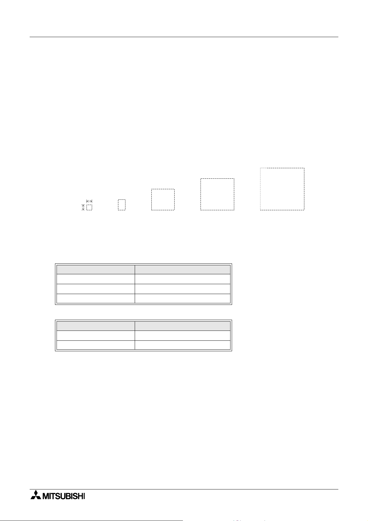
Graphic Operation Terminal GOT-F900 Creation of Display Screens 8
8.5.4 Attribute of display element
The display elements are equipped with detailed set items as attributes.
Representative att ributes are explained below.
Display position:
The X and Y coordinates of the display position are specified. As a mouse is used for the
screen creation software, the coordinates specified by the mouse are registered.
Character size:
1 character: 16 × 8 dots (V × H)
×
4
A
8 dots
0.5
width
8 dots
A
×
1
and longitudinal
×
1
(in both lateral
directions)
A
×
2
(in both lateral
and longitudinal
directions)
A
×
3
(in both lateral
and longitudinal
directions)
A
(in both lateral and
longitudinal directions)
In the case of the following versions or later, high-definition fonts (× 4 or more) and small
character fonts (6 × 8 dots) can be displayed. (For further details, refer to the next page.)
Corresponding version
GOT
Product model name Version
F930GOT V4.10
F940, F943GOT V6.10
F940WGOT V1.10
Screen creation software
Software
GT-Designer SW5D5C-GOTR-PACK V5.05F
FX-PCS-DU/WIN-E V2.50
8-12

Graphic Operation Terminal GOT-F900 Creation of Display Screens 8
• High-definition font
High-definition font display is available only when the f ollowing objects and sizes are
selected and setting for high-definition font is made using the screen creation software.
- Applicable condition
Applicable object
Numeric value display, Numeric input
High-definition font can not be specified for objects other than the above.
Valid size
Lateral magnification
12468
0.5
Longitudinal
magnification
1
2
3
4
lll
lll
lll
Note: Only the magnifications indicated by "l" are valid.
Valid character
17 characters of 0 to 9, A to F and a decimal point
•"6 × 8 dots" font
"6 × 8 dots" font display is available only when the following objects and sizes are selected
and setting for "6 × 8 dots" font is made using the screen creation software.
- Applicable condition
Applicable object
Comment display, Lamp display, Date/Time display, Alarm list display, Alarm history
display, ASCII display, ASCII input, Numeric value display, Numer ic input, Touch switch
"6 × 8 dots" font can not be specified for object other than the above.
Valid size
Lateral magnification
12468
l
Longitudinal
magnification
0.5
1
2
3
4
Note: Only the magnifications indicated by "l" are valid.
Valid character
ASCII characters of character codes 20H to 7FH (96 characters)
8-13

Graphic Operation Terminal GOT-F900 Creation of Display Screens 8
Color specification:
F940WGOT-TWD : 256 colors
F940GOT-SWD, F943GOT-SWD : 8 colors (white, black, red, blue, yellow,
green, purple and light blue)
F930GOT-BWD, F940GOT-LWD, F943GOT-LWD:2 colors (black and white)
- In the case of FX-PCS-DU/WIN-E, display color, background color, needle color and
frame color are available.
- In the case of GT Designer, character color, plate color and frame color are available.
Screen background color:
In the case of both FX-PCS-DU/WIN-E and GT Designer, colors can be specified according to
the display unit.
F930GOT : 2 colors (bla ck and white)
F940GOT, F943GOT : 8 colors
F940WGOT : 256 colors
PLC Device specification:
Specification of devices in PLC (The following apply to the PLCs manufactured by Mitsubishi
Electric.)
- Word device: Timer (T), counter (C), data register (D) and index register (V and Z). In
case of the A Series, link register (W) and file register (R) can be also specified.
- Bit device: Input (X), output (Y), auxiliar y relay (M), state (S), timer (T) and counter (C).
In A Series, F and B can be also specified.
Upper/lower limit:
The upper limit and lower limit of word devices to be displayed are set.
Word devices are displayed within the range determined by the upper and lower limits.
8-14

Graphic Operation Terminal GOT-F900 Creation of Display Screens 8
8.6 Screen call function and overlay function
In the GOT, user screens can be overlaid.
The screen call function which specifies screens to be overlaid using the screen creation
software and the overlay function which specifies screen s to be overlaid from the PLC are
available.
1) Screen call function (For details, refer to Paragraph 8.5.2.)
Screens to be overlaid can be specified preliminarily using the screen creation software.
A base screen and up to five other screens can be overlaid at a time.
2) Overlay function (For details, refer to Paragraph 8.5.3.)
When screens to be overlaid are specified from the PLC (Refer to Sections 11 and 13), a
base screen and up to two other screens can be overlaid at a time.
When this overlay function is used together with the screen call function, screen call
is effective only for the base screen. The screen call function is not e ffective for the
second and third screens to be overlaid.
(If the screen call function is used for the second or third screens, the base screen selected
in the screen call function is overlaid.)
• In both screen call and overlay function, when other functions such as touch keys and
numeric change are displayed, such functions are effective on all of the overlaid screens.
If functions are displayed in a same position, the function on the top screen is effective.
Base screen
Touch key
The base screen is located at the bottom.
If touch keys are displayed in a same posit i on, the touch key on t he ov erl aying screen
2 located at the top is
effective.
Overlaying screen 1
+
Touch key
Overlaying screen 2
+
Touch key
8-15

Graphic Operation Terminal GOT-F900 Creation of Display Screens 8
8.6.1 The writing function of the initial display screen number (GT Designer is used).
When the GOT is turned ON, user screen 1 will be displayed.
To display this screen, the GOT writes ’1’ in the data register assigned in GT Designer for
’programmab le controller screen change on power ON’
The user can set a different screen to be displayed at power ON, in this location.
Applicable version
GOT
Product type name version
F930GOT V4.00
F940, F943GOT V5.00
F940WGOT V1.00
Screen creation software
Product type name version
GT Designer SW5D5C-GOTR-PACK or later
FX-PCS-DU/WIN-E Not supported.
• Set method
4) Additionaly, “Assistance set” of “System requirements setting” is selected.
5) “Write” or “Do not write” is selected.
An initial value is “Write”.
Write : Mode to write “1” in registered for screen change when power supply is
turned ON.
Do not Write : Mode not to write “1” is registered for screen change when power supply
is turned ON.
8-16

Graphic Operation Terminal GOT-F900 Creation of Display Screens 8
8.6.2 Screen call function
When screen call is used, screens are overlaid as shown below in accordance with the screen
creation software used.
1) FX-PCS-DU/WIN-E
When this software is used, 500 user screens Nos . 0 to 499 and the common setting screen
can be overlaid.
The common setting screen is always overlaid by othe r screens.
Accordingly, when screen call is used, the comm on setting screen, b ase screen and u p to
four other screens (that is, up to 6 screens in total) can be overlaid.
Display example
Common setting screen
+
MENU
Call screen 2
+
2) GT Designer
When this software is used, 500 user screens Nos. 1 to 500 can be overlaid.
When screen call is used, the base sc reen and up to five other screens (that is, up to 6
screens in total) can be overlaid.
Base screen
¡n¨
Base screen
A
Call screen 3
Call screen 1
+
+
Call screen 1
B
Call screen 5
Call screen 2
+
Overlay screen realized by
screen call function
ECD
ABCDE
=
MENU
Call screen 3
u
+
+
Call screen 4
+
+
Call screen 5
+
Overlay screen realized by
screen call function
¡n¨
=
u
✕▲▲✕
8-17

Graphic Operation Terminal GOT-F900 Creation of Display Screens 8
8.6.3 Overlay function
The base screen and up to two other screens (3 screens in total) can be overlaid. Perform the
following setting in accordance with the screen creation software used.
1) Setting in FX-PCS-DU/WIN-E
Use control devices to realize screen overlay (Refer to Paragraph 8.6.).
Bit and data devices are available as control devices. Only devices necessary for the
overlay function are described here.
Data register (D), timer (T) and counter (C)
The screen Nos. to be overlaid can be specified using the contents of word devices set as
control devices. The Nos. of the screens currently displayed can be monitored in the PLC.
D
D ( +1)
D ( +2)
D ( +3)
D ( +4)
D ( +5)
D0
D1
D2
D3
D4
D5
In the initial setting, D0 to D5 are selected.
Six consecutive devices starting from "DO" are occupied.
(Refer to Paragraph 8.6.1.)
D0 to D2 specify the scr een Nos. to be displayed. D3 to D5 specifies the sc reen Nos. of
screens currently displayed.
F940GOT(FX-PCS-DU/WIN-E) Sequence program
D0: Specifies the No. of the screen to be
displayed first.
D1: Specifies the No. of the screen to be
displayed second.
D2: Specifies the No. of the screen to be
displayed third.
D3: Stores the No. of the screen currently
displayed.
D4: Stores the No. of the second screen when two
or three screens are overlaid.
D5: Stores the No. of the third screen when three
screens are overlaid.
When overlay is not performed, enter "-1" to both
D1 and D2.
Monitoring in a peripheral unit
User screen Nos. (0 to 500) and system screen
Nos. (1,000 ~) are stored. When overlay is not
performed, "-1" is stored in D4 and D5.
MOV K**** D0
MOV K**** D1
MOV K**** D2
Important point
n
• In FX-PCS-DU/WIN-E, three screens can be overlaid even if the "Overlay Screen" object is
used. In this case, however, the overlay function described here is not available.
8-18

Graphic Operation Terminal GOT-F900 Creation of Display Screens 8
In screen overlay, the screen specified by a word device is treated as the base screen, and the
screens specified by "DO +1" and "DO +2" overlay the base screen. When overlaying screens,
make sure to set "Destination Screen" of the "Change Screen" object to "PLC data register"
and write the screen Nos. to be overlaid to word devices (D+0, D+1 and D+2) as shown in the
table below. When screen overlay will not be performed, enter "-1" or "FFFF (H)" to the
relavent word devices.
D+0 D+1 D+2
Screen No. -1 -1 Base screen
Screen No. Screen No. -1 Base screen + Overlaying screen 1
Screen No. -1 Screen No. Base screen + Overlaying screen 1
Screen No. Screen No. Screen No. Base screen + Overlaying screen 1 + Overlaying screen 2
In the description below, data devices set as initial values are used.
Data devices: D0, D1 and D2
a) No overlay
• Only the screen specified by the control word device D0 is displayed.
Screen specified by D0
(base screen)
A
b) Overlay of two screens
• Two screens specified by the control word devices D0 and D1 are displayed.
• Or two screen specified by the control word devices D0 and D2 can be displayed.
Screen specified by D 0
(base screen)
Screen specified by D 1 Display screen
BA
AB
+
c) Overlay of three screens
• Three screens specified by the control word devices D0, D1 and D2 are displayed.
Screen specified by D0
(base screen)
Screen specified by D1 Display screen
BA
+
Screen specified by D2
+
CC
AB
8-19

Graphic Operation Terminal GOT-F900 Creation of Display Screens 8
• Example of screen overlay
Screen overlay: Each process is monitored. When a material has run short, the material name
is displayed on the screen, and a message is displayed to notify necessity of
supplement of the material.
- Line selector switch
Line 1 input: X0
Line 2 input: X1
- Sensor (for bolt count)
Line 1 input: X2
Line 2 input: X3
- Supplement confirmation button: X4
Program in PLC
Control devices
Data devices: Word devices to specify screen Nos. to be overlaid
D 0
D (0+1)
D (0+2)
Line selector switch
X0
M10
C0
X4 T0
M20
T0
Sensor
X2
Supplement is
completed.
D0
D1
D2
M20
M10
FNC12
P
MOV
FNC12
MOV
FNC12
MOV
FNC12
MOV K1 D0
FNC12
MOV
FNC12
MOV
RST
FNC12
MOV K1 D0
FNC12
MOV
FNC12
MOV
FNC12
MOV
K1 D0
P
K-1 D1
P
K-1 D2
P
P
K10 D1
P
K20 D2
P
P
K11 D1
P
K-1 D2
P
K-1 D1
C0
T0
M20
C0
K1000
K¡
Selects line 1.
Displays screen No. 1.
Stores "-1" in cont rol devices indicating
screens not to be overl ai d.
Counts the number of bolts.
Base screen to be overl ai d
Specify screens to be overlaid.
Screen No. 10
Screen No. 20
Resets the counter by X4 when
supplement is com pl et ed.
Displays mess age No. 11 (which notifies
that supplement of m aterial is completed)
for ¡ seconds.
Base screen to be overl ai d
Specify screens to be overlaid.
(Screen No. 11
Screen overlay is not performed.
Screen overlay is finished.
Stores "-1" in cont rol device.
→
D1
→
D2
→
D1)
Display a)
in the
next page
Display b)
in the
next page
Display c)
in the
next page
Display a)
in the
next page
In the program above, line 1 is selected. If line 2 is selected, screens can be overlaid in the
same way.
8-20

Graphic Operation Terminal GOT-F900 Creation of Display Screens 8
Screen No. 0
DRIVE PREPARATION
1. PLEASE SELECT LINE 1
OR LINE 2
START
Touch key No. 0
PLC: X0 = ON
START key: ON
Screen No. 1
LINE 1 DRIVING
MENU MENU
Screen currently being created
After the switch line is selected, the next screen is displayed when
the START key is pressed (= becomes ON). The registered setting of
screen changeover is shared by all screens.
Setting shared by all screens (Change Screen)
Screen changeover condit i on
Control Input
1
Touch key No. 0
2
Touch key No. 0
PLC: X1 = ON
START key: ON
Bit Device
X0
X1
When the MENU item (START key) is
Destination
Screen
1
2
Save Current
Screen
Not effective
Not effective
pressed, screen No. 0 is displayed.
Screen No. 2
LINE 2 DRIVING
Setting for individual screen(Change Screen)
Screen changeover
condition
Control
key No. 0
key No. 0
key No. 0
Input
Touch
Touch
Touch
Bit Device
Not
effective
Not
effective
Not
effective
Destination
Screen
0
PC
PC
Save
Current
Screen
Not
effective
Not
effective
Not
effective
Touch key No. 0
Overlay of three screens: Screen Nos. 10 and 20 overlay screen No. 1.
In this overlay example, line 1 (screen No. 1) is adopted.
Screen No. 10
PLEASE REPLENISH THE
MATERIAL
Screen No. 20
BOLT
M3 × 30
Display screen realized by overlay
No. 1 + No. 10 + No. 20
PLEASE REPLENISH THE
MATERIAL
BOLT
M3
Overlay of two screens: Screen No. 11 overlays screen No. 1.
Display screen realized by overlay
Screen No. 11
MATERIAL REPLENISHMENT
COMPLETE
No. 1 + No. 11
MATERIAL REPLENISHMENT
COMPLETE
LINE 1 DRIVING
×
30
LINE 1 DRIVING
8-21

Graphic Operation Terminal GOT-F900 Creation of Display Screens 8
2) Setting in GT Designer
In overlay, use word devices for "Change Screen".
Set the base screen No. and the overlaying screen (= overlap window) Nos. in accordance
with the contents of the word devices set in "Change Screen".
Setting of word devices for screen changeover
Base screen:Word device (The initial value is set to D0.)
Overlap window 1:Word device (The initial value is not set.)
Overlap window 2:Word device (The initial value is not set.)
The base screen, the overlap window 1 and the overlap window 2 can be specified using
arbitrary word devic e s. (The word devices may not be consecutive.)
When overla y is not perf ormed, enter "-1" to the specified devices or perform setting so that
overlap windows are not used.
The screen Nos. currently displayed can be check ed using "Write Device" in "System
Information" in the screen creation software. (Refer to Paragraph 8.6.)
Write devices:Head word device
"Head + 1" word device
"Head + 2" word device
The specified screens are overlaid as shown below.
Base
screen
Screen No. -1 -1 Base screen
Screen No. Screen No. -1 Base screen + Overlap window 1
Screen No. -1 Screen No. Base screen + Overlap window 2
Screen No. Screen No. Screen No. Base screen + Overlap window 1 + Overlap window 2
Overlap
window 1
Overlap
window 2
8-22

Graphic Operation Terminal GOT-F900 Creation of Display Screens 8
a) No overlay
• Only the base screen is displayed.
Screen No. specif y i ng
base screen
(Base screen)
A
b) Overla y of two screens
• Two screens specified by D0 and D1, the base screen and the overlap window 1, are
overlaid.
• Or two screens specified by D0 (base screen) and D2 (overlap window 2) can be
overl aid.
Screen No. specifyi ng
base screen
(Base screen)
Screen No. specifyi ng
overlap window 1
BA
Display screen
AB
+
c) Overlay of three screens
• Three screens specified by D0, D1 and D21, the base screen, overlap window 1 and
overlap window 2, ar e overlaid.
Screen No. specif y i ng
base screen
(Base screen)
Screen No. specif y i ng
overlap window 1
BA
+
Screen No. specif y i ng
overlap window 2
+
Display screen
CC
AB
8-23

Graphic Operation Terminal GOT-F900 Creation of Display Screens 8
• Example of screen overlay
Screen overlay: Each process is monitored. When a material has run short, the material
name is display ed on the screen, and a message is displayed to notify
necessity of supplement of the material.
- Line selector switch
Line 1 input: X0
Line 2 input: X1
- Sensor (for bolt count)
Line 1 input: X2
Line 2 input: X3
- Supplement confirmation button: X4
Program in PLC
Screen changeover
Word devices: Word devices to specify screen Nos. to overlay/be overlaid
Base screen
Overlap window 1
Overlap window 2
Line selector switch
X0
Sensor
M10
C0
X4 T0
M20
M20
X2
Supplement is
completed.
D0
D1
Set them in "Change Screen" in "Common Setting" in
GT Designer.
D2
M10
P
MOV
MOV
MOV
MOV K2 D0
MOV
MOV
RST
MOV K2 D0
K2 D0
P
K-1 D1
P
K-1 D2
P
P
K10 D1
P
K20 D2
P
C0
T0
M20
C0
K1000
K¡
Selects the line 1.
Displays the sc reen No. 2.
Stores "-1" in control dev ices indicating
screens not to be overlaid.
Counts the number of bolts.
Base screen to be overlaid
Specify the screens to be overlaid.
Screen No. 10
Screen No. 20
Resets the counter by X 4 when
supplement is complet ed.
Displays the mes sage No. 11 (which
notifies that supplem ent of material is
completed) for ¡ seconds.
Base screen to be overlaid
→
D1
→
D2
Display a)
in the
next page
Display b)
in the
next page
Display c)
in the
next page
Specify the screens to be overlaid.
(Screen No. 11
Screens overlay is not performed.
Screen overlay is fini shed.
Stores "-1" in control dev ice.
→
D1)
Display a)
in the
next page
T0
MOV
MOV
P
K11 D1
P
K-1 D2
P
K-1 D1MOV
In the program above, the line 1 is selected. Even if the line 2 is selected, screens can be
overlaid in the same way.
8-24

Graphic Operation Terminal GOT-F900 Creation of Display Screens 8
Screen No. 1
DRIVE PREPARATION
1. PLEASE SELECT LINE 1
OR LINE 2
START
Touch key
PLC: X0 = ON
START key: ON
Screen No. 2
LINE 1 DRIVING
MENU MENU
No overlay a)
Screen currently being displayed
Set the screen preliminarily so that screen No. 2 is displayed when
the START touch key is pressed.
PLC: X1 = ON
START key: ON
Screen No. 3
LINE 2 DRIVING
Set the MENU (START) touch key
so that screen No. 1 is displayed
when the MENU (START)
touch key is pressed.
Touch key
Overlay of three screens: Screen Nos. 10 and 20 overlay screen No. 1.
In this overlay example, line 1 (screen No. 2) is adopted.
Screen No. 10
b)
PLEASE REPLENISH THE
MATERIAL
Screen No. 20
BOLT
M3 ´ 30
Display screen realized by overlay
No. 2 + No. 10 + No. 20
PLEASE REPLENISH THE
MATERIAL
BOLT
M3 ´ 30
Overlay of two screens: Screen No. 11 overlays screen No. 2.
Display screen realized by overlay
Screen No. 11
MATERIAL REPLENISHMENT
COMPLETE
No. 1 + No. 11
MATERIAL REPLENISHMENT
COMPLETE
LINE 1 DRIVING
LINE 1 DRIVING
8-25

Graphic Operation Terminal GOT-F900 Creation of Display Screens 8
8.7 Control devices and system i n formation
Devices are required to be assigned to change over the display screen of the GOT from the
PLC, read the status information including the batter y status in the GOT and the alarm
occurrence data from the PLC. The term "control device" is used in FX-PCS-DU/WIN-E.
The term "system information" is used in GT Designer.
8.7.1 Control device (setting in FX-PCS-DU/WIN-E)
• Bit devices: Eight bit devices (X, Y, M, S, T and C) in the PLC are occupied. M0 to M7 are
specified when the GOT is shipped from the factory.
• Word devices: Seven word devices (D, T and C) in the PLC are occupied. D0 to D7 are
specified when the GOT is shipped from the factory.
Details of bit devices
• Occupied bit devices are used for communication using ON/OFF signals.
[ When auxiliary relay M0 is assigned ]
Auxiliary
relay
*1 M0 When this bit device becomes ON from OFF, the alarm history is cleared.
*2 M1
M2
*1
M3
M4 This bit device remains ON while sampling is performed in the sampling mode.
M5 This bit device becomes ON as a flag when setting of a number is completed.
*2
M6
M7 Unused
This bit device remains ON while a device assigned by the alarm function
remains ON.
When this bit device becomes ON, the backlight of the display screen is turned
OFF after a specified time.
When this bit device becomes ON from OFF, the data acquired in the sampling
mode is cleared.
This bit device becomes ON when the backup battery power of the GOT has
dropped.
Contents of control
*1 The PLC gives instructions to the GOT. Coils are turned ON/OFF in the PLC programs.
*2 The GOT transmits the information to the PLC. Contacts are used in the PLC programs.
8-26

Graphic Operation Terminal GOT-F900 Creation of Display Screens 8
Details of wor d devices
• Occupied word devices (which may be called data device s) are used to specify screen Nos.
to be displayed and confirm the screens currently displayed.
[ When data register D0 is assigned ]
Data register Contents of control
These word devices specify screen Nos. to be displayed.
D0: Specifies the screen No. of the base screen displayed when only one screen is
D0
D1
D2
D3
D4
D5
D6 This word device specifies a file No. to be read/written.
D7 This word devices indicates the ID of the object whose input is completed.
displayed.
D1: Specifies the screen No. of overlaying screen 1 displayed when two screens are
displayed.
D2: Specifies the screen No. of overlaying screen 2 displayed when three screens are
displayed.
These word devices store screen Nos. of the screens currently being displayed.
D3: Stores the screen No. of the base screen currently being displayed.
D4: Stores the screen No. of the second screen currently being displayed.
D5: Stores the screen No. of the third screen currently being displayed.
8-27

Graphic Operation Terminal GOT-F900 Creation of Display Screens 8
• Control devices execute the following oper ations.
When bit devices M0 to M7, word devices D0 to D7 are assigned
GOT Sequence program
Bit devices
When M0 becomes ON from OFF, the alarm hi story is
cleared.
M0
M1 remains ON while a correspondi ng al arm device
remains ON.
When M2 becomes ON, the dis pl ay screen back light is
extinguished after a specified time.
When M3 becomes ON from OFF, t he data acquired in the
sampling mode is clea red.
M4 remains ON while sampling is performed in the
sampling mode.
M5 becomes ON when setti ng of a number is completed.
M6 becomes ON when the back up bat tery power of the
GOT has dropped.
M7 is not used.
Word devices
D0 to D2
2
1
Screens stored in D0 t o D2 are
displayed.
When screen overlay is not
0
performed, "-1" is stored.
M1
M4
M5
M6
MOV
MOV
MOV
M2
M3
K0 D0
K1 D1
K2 D2
D3 to D5
5
4
D6 stores a data file No.
D7 indicates the ID No. of an object.
ID
Screens currently dis played are
stored in D3 to D5.
3
User screens Nos. 0 to 499
and system screens No. 1000
and later are available.
When screen overlay is not
performed, "-1" is stored in D4
and D5.
D0 to D2 specify the
screen Nos. of screen s to
overlay/be overlaid.
D3
D3 to D5 store the
D4
screen Nos. of screen s
D5
currently displayed.
MOV K¡ D6
D7 stores the ID No. of a
manipulated object.
D7
• The number of occupied points increases when connected to a bar code reader.
For further details, refer to "GOT-F900 SERIES HARDWARE MANUAL".
8-28

Graphic Operation Terminal GOT-F900 Creation of Display Screens 8
8.7.2 System information (setting in GT Designer)
The following word devices can be specified as system information devices for read and write.
• Read devices:
One or two 16-bit word devices are occupied.
(The number of occupied devices can be changed using the screen creation software.)
No devices are set when the GOT is shipped from the factory.
• Wr i te devices:
Five 16-bit word devices are occupied.
(Fifteen word devices are occupied in principle in the screen creation s oftw are . How ever,
write devices not used in the GOT can be used as general word devices.)
No devices are set when the GOT is shipped from the factory.
Details of read devices
• Head of specified word devices:
Reads the GOT information to its bits 0 to 2 (b0 to b2).
"Head +1" of specified word devices:
Specifies the recipe No. to be read from/written to the PLC using the recipe function.
[ When data register D10 is assigned ]
Data register Contents of control
b0 When b0 becomes ON from OFF, the alarm history in the GOT is cleared.
When b1 becomes ON, the display screen backlight is extinguished after a specified
b1
D10
D11 Specifies the recipe No. to be read from/written to the PLC using the recipe function.
time.
b2 When b2 becomes ON from OFF, the data acquired in the sampling mode is cleared.
If b8 is ON, the keyboard for password input is displayed automatically when a high-
b8
security-level screen i s selected.
*1
*1 F930GOT: V4.00 or later, F940GOT: V6.00 or later, F940WGOT: V1.00 or later
8-29

Graphic Operation Terminal GOT-F900 Creation of Display Screens 8
Details of write devices
• Head to "Head +4" of specified word devices: Store the screen Nos. currently displayed.
"Head +5" of specified word devices: Turns ON/OFF its bits 0 to 3 (b0 to b3) to control the
GOT.
[ When data register D20 is assigned ]
Data register Contents of control
These data registers store the screen Nos. currently displayed in screen mode.
D20
D21
D22
D23 Stores the ID of an object whose input is completed.
D20: Stores the screen No. of the base screen currently displayed.
D21: Stores the screen No. of the second screen (overlap window 1) when two
screens are overlaid.
D22: Stores the screen No. of the third screen (overlap window 2) when three screens
are overlaid.
b0 b0 remains ON while a device assigned in the alarm function remains ON.
b1 b1 remains ON while sampling is performed in the sampling mode.
D24
D25 to D34 Unused (They can be used as general word devices in sequence programs.)
b2 b2 becomes ON when numeric input is completed.
b3 b3 becomes ON when the backup battery power of the GOT has dropped.
b8
It remains ON while data changing for numeric input or ASCII input is performed.
*1 F930GOT: V4.00 or later, F940GOT: V6.00 or later, F940WGOT: V1.00 or later
• The number of occupied points increases when connected to a bar code reader.
For further details, refer to "GOT-F900 SERIES HARDWARE MANUAL".
*1
8-30

Graphic Operation Terminal GOT-F900 Creation of Display Screens 8
• Device assigned for system information execute the following operations.
When the following devices are assigned
Read devices
Write devices
Read devices
When M10 becomes ON from OFF, t he al arm hi story is
cleared.
D10 (b0 to b2 are developed to M10 to M12.)
:
D11
D20 to D24 (b0 to b3 are developed to M20 to M23.)
:
GOT Sequence program
are assigned.
M10
When M11 becomes ON, the dis pl ay screen backlight is
extinguished after a specified time.
When M12 becomes ON from OFF, t he data acquired in
the sampling mode is cleared.
If M18 is ON, the key board for password input is dis pl ayed
automatically when a hi gh-security-level screen is selected.
D11 stores the recipe No.
Write devices
D20 to D22
5
4
D23 stores the ID No. of an obj ect.
ID
The screen Nos. of screens
currently displayed ar e stored in
3
D20 to D22.
User screens Nos. 0 to 499
and system screens No. 1000
and later are available.
When screen overlay is not
performed, "-1" is stored in
D21 and D22.
M13 is not used (unusable).
Always ON
D20 to D22 store the screen
Nos. of screens currently
displayed.
D23 stores the ID No. of a
manipulated object.
D23
MOV
¡
M11
M12
M12
D11K
M20 remains ON while an alarm devi ce remains ON.
M21 remains ON while sampli ng i s performed.
M22 becomes ON when change of numeri c data is
completed.
M23 become ON when the backup battery power of the GOT
has dropped.
It becomes ON while c hangi ng of numeric or ASCII data is
performed.
Always ON
K3M20D24MOV
M20
M21
M22
M23
M28
8-31

Graphic Operation Terminal GOT-F900 Creation of Display Screens 8
MEMO
8-32

Graphic Operation Terminal GOT-F900
9. Screen mode
This section describes the mode in which user screens are displayed.
Confirm the outline of what can be displayed and the operating procedures in screen mode.
For contents related to the screen design, refer to Sections 18 to 21.
9.1 Display format
F930GOT, F940GOT, F943GOT
• Only horizontal display is available.
F940WGOT
Horizontal and vertical display are available.
• The dot pitch of F940WGOT is 0.324 (horizontal) × 0.375 (vertical).
It is therefore displayed lengthwise at a ratio of about 1:1.16.
Screen mode 9
9-1

Graphic Operation Terminal GOT-F900 Screen mode 9
9.2 Display size
F930GOT
240dots
117mm(4.61")
80dots
42mm(1.65")
F940GOT, F943GOT
320dots
115mm(4.53")
240dots
86mm(3.39")
9-2

Graphic Operation Terminal GOT-F900 Screen mode 9
F940WGOT (Horizontal display)
480dots
155.5mm(6.12")
234dots
87.8mm(3.46")
F940WGOT (Vertical display)
480dots
234dots
87.8mm(3.46")
155.5mm(6.12")
9-3

Graphic Operation Terminal GOT-F900 Screen mode 9
9.3 Outline of screen mode
In the screen mode, screens created by the user are displayed. In addition, alarm messag es
are displa yed.
On one display screen, characters, straight lines, rectangles, circles, etc. which are classified
in accordance with their functions are combine d and displ ayed.
When there are two or more user screens, they can be changed over using operation keys in
the GOT or using the PLC. (The user can set the condition to change over the screens and the
screen to be displayed next.)
On one screen, the following elements can be displayed. (In the display example below, only a
selection of the available functions are used.)
Examples of display screen (F940GOT)
Text
MITSUBISHI
Circle
F940GOT
MONITOR
13:26:05 56238
Straight line
Time
Numeric
START STOP 0:EMS
Bar graphRectangleIndicator (reverse)
9-4

Graphic Operation Terminal GOT-F900 Screen mode 9
OUT
I N
OUT
CPU¥E
PROG¥E
5
4
3
2
1
0
7
6
5
4
3
2
1
0
X7
X6
X5
X4
X3
X2
X1
X0
COM
N
L
Y5
Y4
Y3
Y2
COM2
Y1
COM1
Y0
COM0
COM
24+
RUN
POWER
The functions used in the display example on the previous page can be mainly classified into
four types, shown below.
(For details of each function, refer to Sections 10 and 12.)
GOT PLC
Display function
Data display function
Data transfer function :
:
This function display s the registered
contents in the speci fied size in the
specified position.
Characters, external characters,
straight lines, ci rcles, etc.
:
This function monitors the contents of
devices in the PLC in the specified
size and in the specifi ed position.
The specified area can be inv erted by
turning ON/OFF bit devices i n t he
PLC.
Numerics, bar graphs, i ndi cators, etc.
*1 The information inside t he PLC is
monitored.
Data is transferred to the PLC.
This function turns ON/OFF specified
devices in the PLC and overwrites
data when a specified input
(operation key, touch key, etc.) is
given.
Touch keys, ten-key pad, etc.
Screen changeover funct i on
:
This function sets the
screen to be displayed
next and the screen
changeover condition.
*1 A part of the data display function can change set values and current values of word
devices (T, C, D, Z and V) on the screen. The operating procedure is described in the
next page.
9-5

Graphic Operation Terminal GOT-F900 Screen mode 9
9.4 Number of registered screen construction elements
Number of registered screen construction elements (Common to F930GOT, F940GOT,
F943GOT and F940WGOT)
Screen construction element
name
GT Designer
Ascii display
Ascii input
Numerical
display
Numerical
input
Comment
display (word
specification)
Bar graph Bar graph
Part Display
(word
specification)
Panel meter Panel meter
Statistics
graph
Trend graph
Line graph
Comment
display (bit
specification)
Lamp
Part Display
(bit
specification)
Clock display
FX-PCS-DU/
WIN-E
Ascii 10101010
Number
Library Text
Library Image
Circle graph
Proportional bar
graph
Proportional Pie
graph
Trend graph
(sampling)
Line graph
(batch)
Text Indicator
Indicator
Overlay Screen
Label Indication
Image Indication
Buzzer
Date
Time
Number of registered objects
[A] [B] [B’] [C]
Per screen
50 50 50 50
10 10 10 10
1111
1111
50 50 50 50
10 10 10 10
Common set
screen
Screen call
Number of
displayable
objects
9-6

Graphic Operation Terminal GOT-F900 Screen mode 9
Screen construction element
name
GT Designer
Touch key
Touch switch
Panel kitKeyboard 1111
Alarm history
display
Alarm list
display (user
alarm)
Floating Alarm
display
FX-PCS-DU/
WIN-E
Switch
Send Databank
Increment
Decrement
Data Setting
Chenge Screen
Touch key
Alarm History
display
Alarm List
(user alarm)
Moving Alarm
display
[A] [B] [B’] [C]
Per screen
50 50 50 50
50 50 50 50Write constant
1111
1111
1111
Number of registered objects
Common set
screen
Screen call
Number of
displayable
objects
The number of objects displayable on one screen of the GOT is shown in [C]. The confi gurati on
is as follows: [A] + [B] + [B’] ≤ [C]
When overlay is performed using the screen overlay function or lamp (screen) function, the
number of displayable objects is also as sho w n in [C].
Number of objects registered in library
Library name Number
Text library 2000
Image library 2000
Data capacity
Item Description
256 Kbytes (user screen, external characters, etc.) ... F930GOT
Full-screen data size
512 Kbytes (user screen, external characters, etc.) ... F940GOT, F943GOT
1 Mbyte (user screen, external characters, etc.) ... F940WGOT
9-7

Graphic Operation Terminal GOT-F900 Screen mode 9
9.5 Change of displayed data
Among the data displayed on the user screen, numeric data indicating set values and current
values of word devices in the PLC can be changed by ke y operation.
In FX-PCS-DU/WIN -E, "Number" and "A scii" can be change d. In GT Designer, "Numerical
Input" and "Ascii input" can be changed.
9.5.1 Common contents in data change
This paragraph describes the common contents when changing numeric data and ASCII code
data.
• By touching a numeric or ASCII code on the display screen, it can be changed.
*1 In FX-PCS-DU/WIN-E, "Number" and "Ascii" should have been set to "PERMIT".
In GT Designer, "Numerical input" and "Ascii Input" can be changed.
• A numeral can be entered using two methods. In the first method, the keyboard for numeric
input is always displayed. In the second method, the keyboard can be called when an input
is required.
[ When the keyboard is always displayed ]
OPERATION STATE MONITOR
CURRENT
VALUE
9 -
051627384
[ When the keyboard is calle d ]
OPERATION STATE MONITOR
CURRENT
VALUE
123
5
678
849
516
273
0
4
CLR
ENT
4123
CLR
- ENT
Cursor
display
Cursor
displa
y
• When a numeric or ASCII code displayed on the
screen is touched, a cursor is displayed and the
numeric or ASCII code can be changed using the
on screen keyboard.
When GT Designer is used, "Project Unit" in
"Auxiliary Setting" in "Common Setting" should
have been set so that the key window is open.
• Press the CLR key to cancel the input.
Press the ENT key to execute the input.
• When selecting another numeric or ASCII code,
touch it on the screen or select it using the and
keys.
• If the keyboard is not displayed on screen, when a
numeric or ASCII code touched, the ten-key pad is
displayed as shown on the left so that numerics
can be entered.
• To enter a numeric in hexadecimal or change the
keyboard design, select an appropriate keyboard
using the "Keyboard" object.
• When text is to be entered using ASCII codes, make sure that the keyboard to input
text is always displayed on the screen. When the keyboard is used in GT Designer,
the keyboard should be created using key codes for touch switches.
When the keyboard is called, only 0 to 9 can be entered.
9-8

Graphic Operation Terminal GOT-F900 Screen mode 9
Data change condition:Numeric and ASCII codes cannot be changed in the following cases.
1) GOT status
- While change is forbidden (During communication with FX-PCS-DU/WIN-E)
When the data change target object is set to "FORBID".
Countermeasures: Set the object to "PERMIT".
- When an input value is outside the range from the lower limit to the upper limit
The upper limit and lower limit are provi ded to indicate the allo wa b le data setting r ange . If
the input value is outside this range, it is not accepted.
Countermeasures: Change the upper/lower limi t value.
- When "****" is displayed on the screen
When a device No. not present in the PLC is monitored, the numeric data is displayed as
"****" on the screen.
Countermeasures: Change the device No. whose numeric data is to be monitored on the
screen.
For the countermeasures above, numeric setting should be changed in the screen
creation software.
2) PLC status
- When an EPROM memory is mounted in the FX/A Series PLC, set values of timers,
counters and current values of file registers cannot be changed.
- When an EEPROM memory is mounted in the FX Series PLC or while the FX/A Series
PLC is running, set values of timers, counters and current values of file registers cannot
be changed.
- When an entry code is registered in the FX/A Series PLC, set values of timers, counters
and current values of file registers cannot be changed. Reset the entry code.
Important point
nnnn
Timing of data change for "Number" ("Numerical Input") and "Ascii" ("Ascii Input")
Data is changed in the PLC at the following times.
When new data is entered and the ENT key is pressed, the new data is transferred to the
PLC. When the CLR key is pressed before the ENT key, the new data is ignored and the
existing data is kept registered.
Layout of "Number" ("Numerical Input") and "Ascii" ("Ascii Input")
A touch key can occupy 12 (horizontal direction) × 20 (vertical direction) dots. When a touch
key occupies an area equivalent to or more than the half of 12 × 20 dots, it is recognized as
touch key.
When half- or full-width numerics and ASCII codes are laid out, a touch key may not be
recognized as touch key depending on its position. In such a case, change the layout, display
the touch key with a frame or display the touch key in a size whose vertical dimension is twice
or larger. (Refer to Paragraphs 10.5.1 and 12.5.1.)
9-9

Graphic Operation Terminal GOT-F900 Screen mode 9
9.5.2 Decimal point input function
Decimal points can be entered if a touch switch to which the key code for decimal point (002E)
is assigned is included when data change is performed.
Applicable version
GOT
Product model name Version
F930GOT V4.00 or later
F940, F943GOT V6.00 or later
F940WGOT V1.00 or later
Screen creation software
Software name Applicable version
GT Designer SW1D5C-GOTR-PACK(A) or later
FX-PCS-DU/WIN-E V2.00 or later
* Decimal points cannot be entered in a key window displayed in the standard form.
It is necessary to create a key window using the key window customizing function (refer to
9.5.4) or display a keyboard including a touch key for decimal point on the screen.
• Example of display of numeric input: Displa y device D100, Signed decimal number
D100
12345 = 1 2 3 . 4 5
With a touch switch for decimal
point Enter
[ 1 ] [ 2 ] [ . ] [ 3 ].
Display digit number: 6 digits (including a decimal point)
When changing to 12.30
Decimal digit number: 2 digits
Without a touch switch for
decimal point Enter
[ 1 ] [ 2 ] [ 3 ] [ 0 ].
* (D100) "1230" is entered into the PLC whether a decimal point exists or not.
Note: Decimal point input does not mean changing the display position of a decimal point
arbitrarily.
The display digit number and decimal digit number cannot be exceeded.
9-10
 Loading...