

Page 1

ENGINE
F8QT SERIES
CONTENTS
GENERAL INFORMATION 11A-0-3...............................
1. SPECIFICATIONS 11A-1-1...................................
SERVICE SPECIFICATIONS 11A-1-1........................
TORQUE SPECIFICATIONS 11A-1-5........................
FORM-IN-PLACE GASKET 11A-1-8.........................
2. SPECIAL TOOLS 11A-2-1....................................
3. CRANKSHAFT PULLEY 11A-3-1..............................
4. TIMING BELT 11A-4-1.......................................
5. WATER PUMP 11A-5-1......................................
6. THERMOSTAT 11A-6-1......................................
7. WATER HOSES AND PIPES 11A-7-1..........................
8. ENGINE COOLANT TEMPERATURE SENSOR 11A-8-1.........
9. GLOW PLUGS 11A-9-1......................................
10. TURBOCHARGER 11A-10-1...................................
11. INTAKE AND EXHAUST MANIFOLDS 11A-11-1.................
12. ROCKER COVER AND CYLINDER HEAD 11A-12-1..............
13. CAMSHAFT, INTAKE AND EXHAUST VALVES 11A-13-1.........
14. VACUUM PUMP 11A-14-1.....................................
15. OIL COOLER AND OIL FILTER 11A-15-1.......................
16. OIL PAN, OIL PUMP AND OIL JETS 11A-16-1...................
17. INTERMEDIATE SHAFT AND INTERMEDIATE
SHAFT BEARINGS 11A-17-1..................................
18. FUEL INJECTION NOZZLE 11A-18-1...........................
19. FUEL INJECTION PUMP 11A-19-1.............................
20. PISTONS AND CONNECTING RODS 11A-20-1..................
21. PISTONS AND PISTON PINS 11A-21-1.........................
22. FLYWHEEL 11A-22-1.........................................
23. CRANKSHAFT AND CYLINDER BLOCK 11A-23-1...............
11A-0-1
E
July 1996Mitsubishi Motors Corporation
PWEE9602
Page 2

11A-0-2
NOTES
E
July 1996Mitsubishi Motors Corporation
PWEE9602
Page 3
F8QT ENGINE -
GENERAL INFORMATION
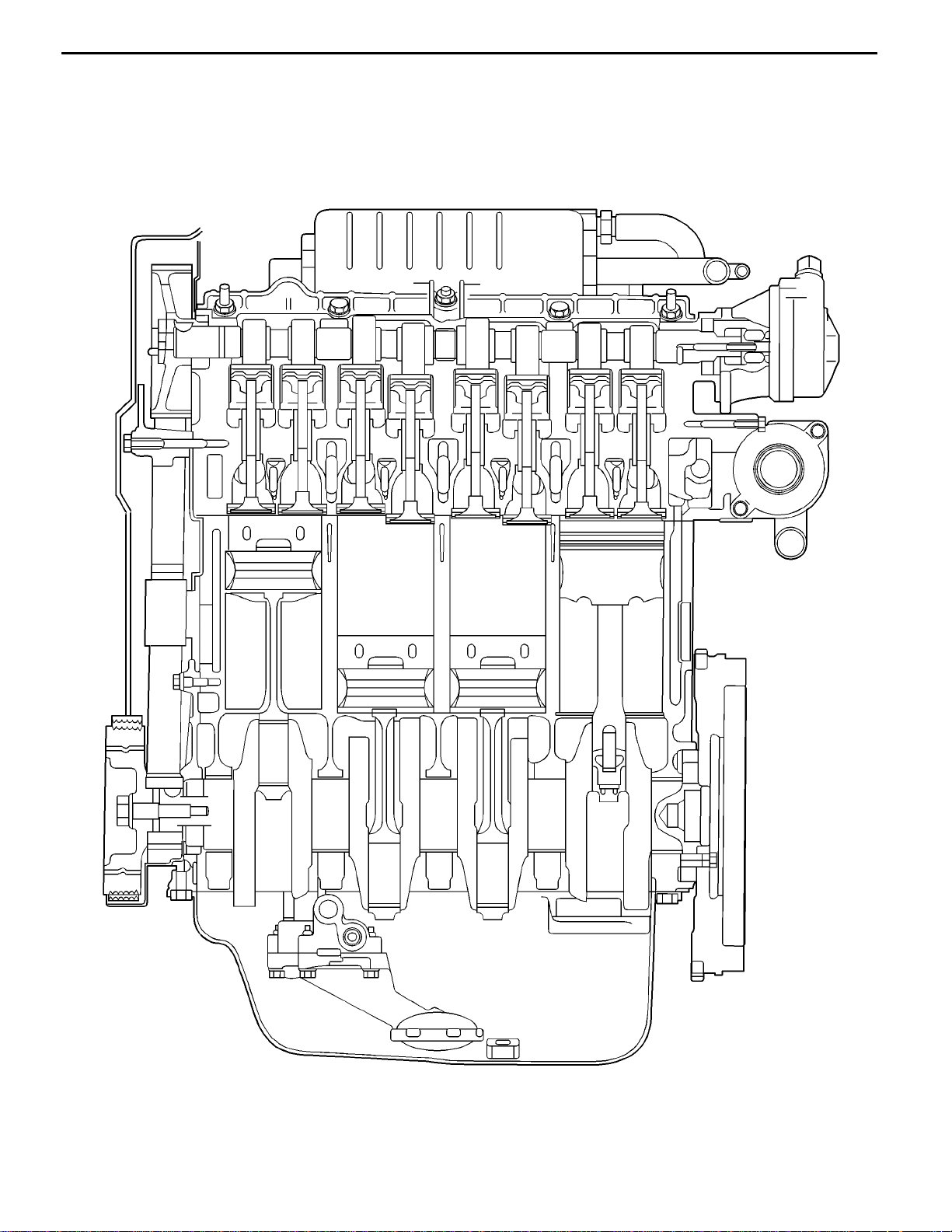
SECTIONAL VIEW OF ENGINE
General Information
11A-0-3
REN0137
E
July 1996Mitsubishi Motors Corporation
PWEE9602
Page 4
11A-0-4
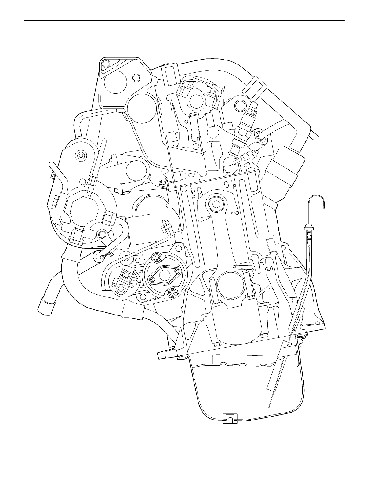
F8QT ENGINE -
SECTIONAL VIEW OF ENGINE
General Information
REN0138
E
July 1996Mitsubishi Motors Corporation
PWEE9602
Page 5
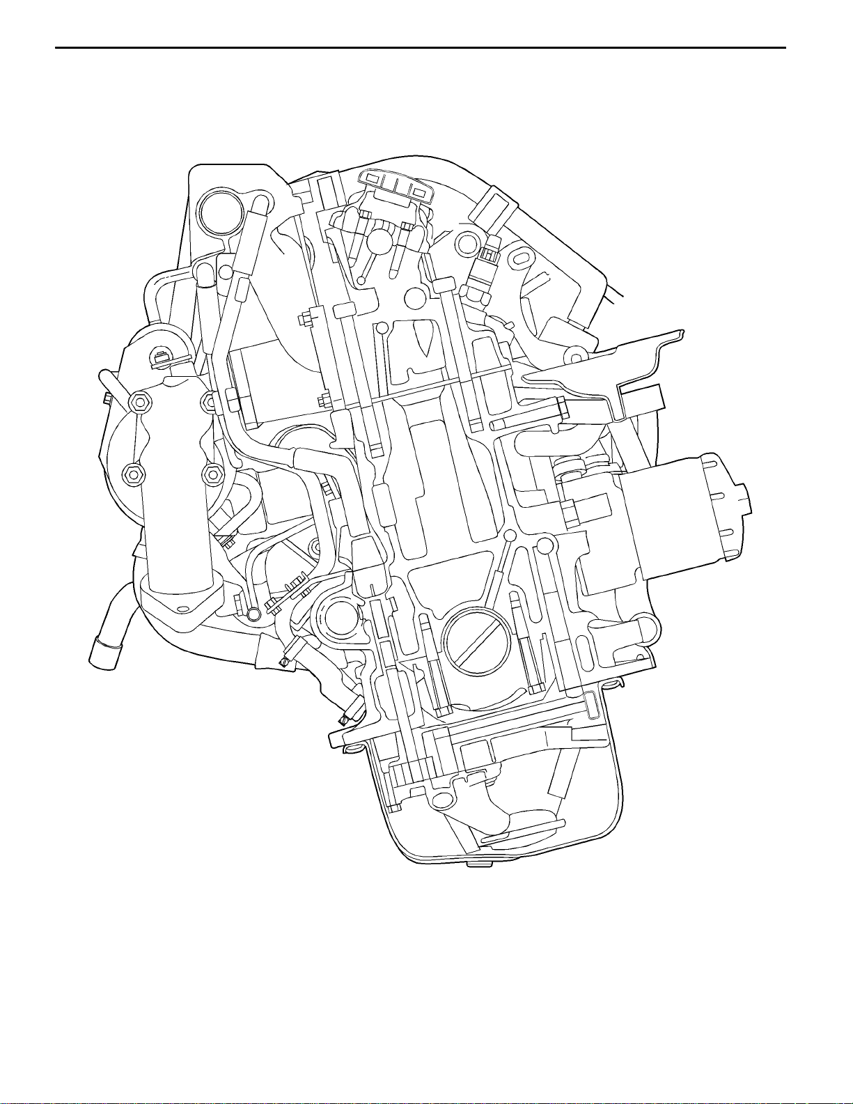
F8QT ENGINE -
SECTIONAL VIEW OF ENGINE
General Information
11A-0-5
REN0139
E
July 1996Mitsubishi Motors Corporation
PWEE9602
Page 6
11A-0-6
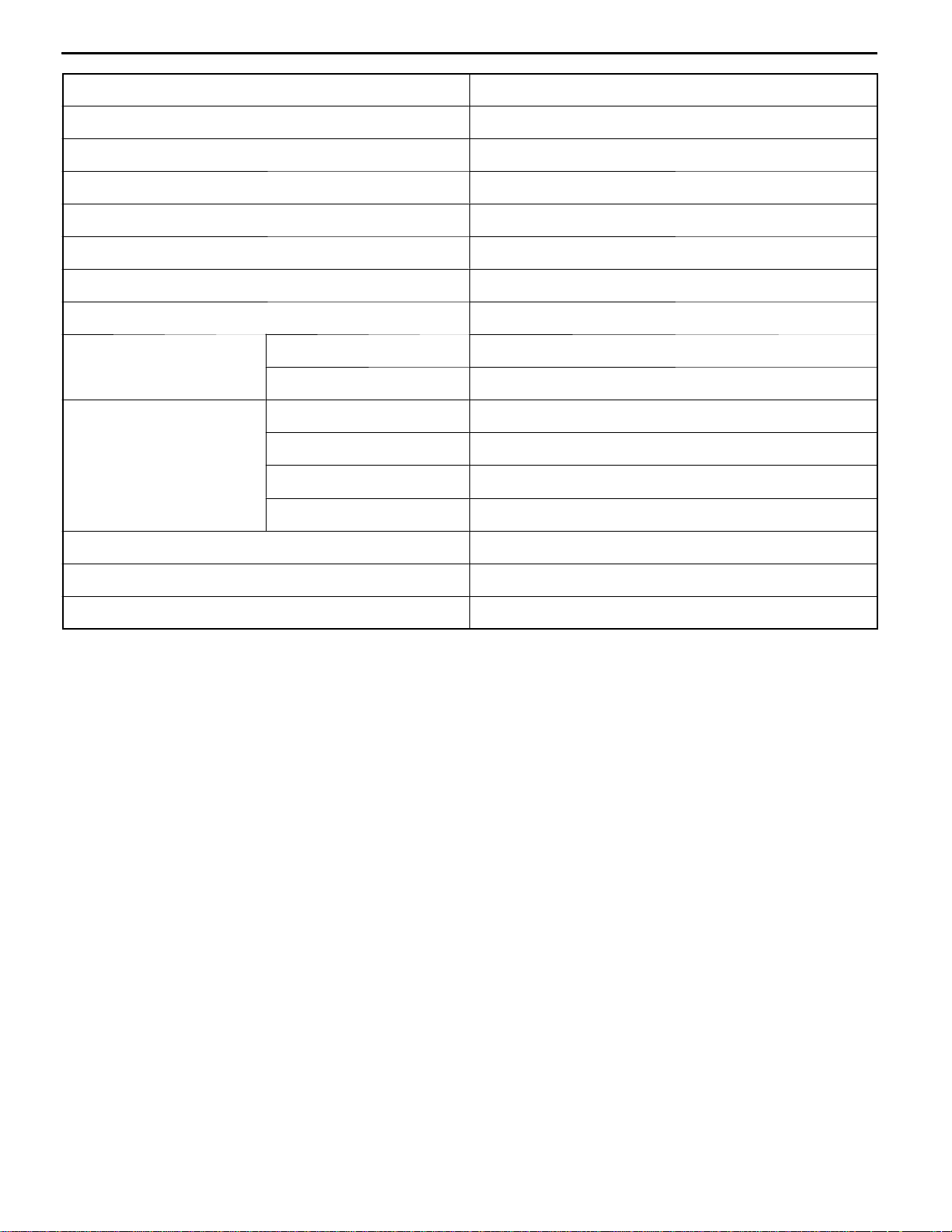
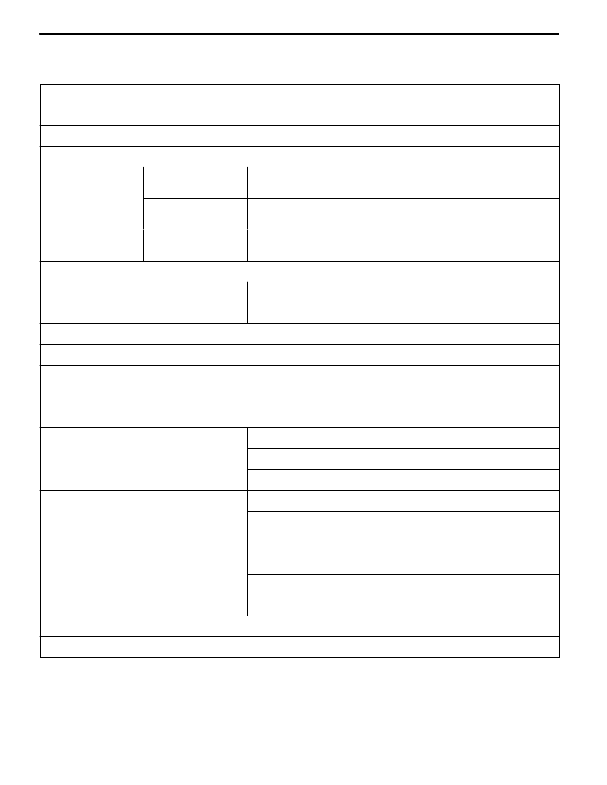
Description Specifications
Type F8QT diesel engine
Number and arrangement of cylinders 4 in-line
Combustion chamber Swirl chamber
F8QT ENGINE -
General Information
Total displacement 1870 cm
Cylinder bore ´ stroke 80 ´ 93 mm
Compression ratio 21
V alve mechanism Single overhead camshaft
Number of valves Intake 4
Exhaust 4
V alve timing Intake opening 0_ BTDC
Intake closing 18_ ABDC
Exhaust opening 41_ BBDC
Exhaust closing 0_ ATDC
Turbocharger Exhaust gas turbocharger
Intercooler (charge cooling) Air-cooled
Fuel injection pump Electric with immobilizer
3
E
July 1996Mitsubishi Motors Corporation
PWEE9602
Page 7
F8QT ENGINE -
Specifications
1. SPECIFICATIONS
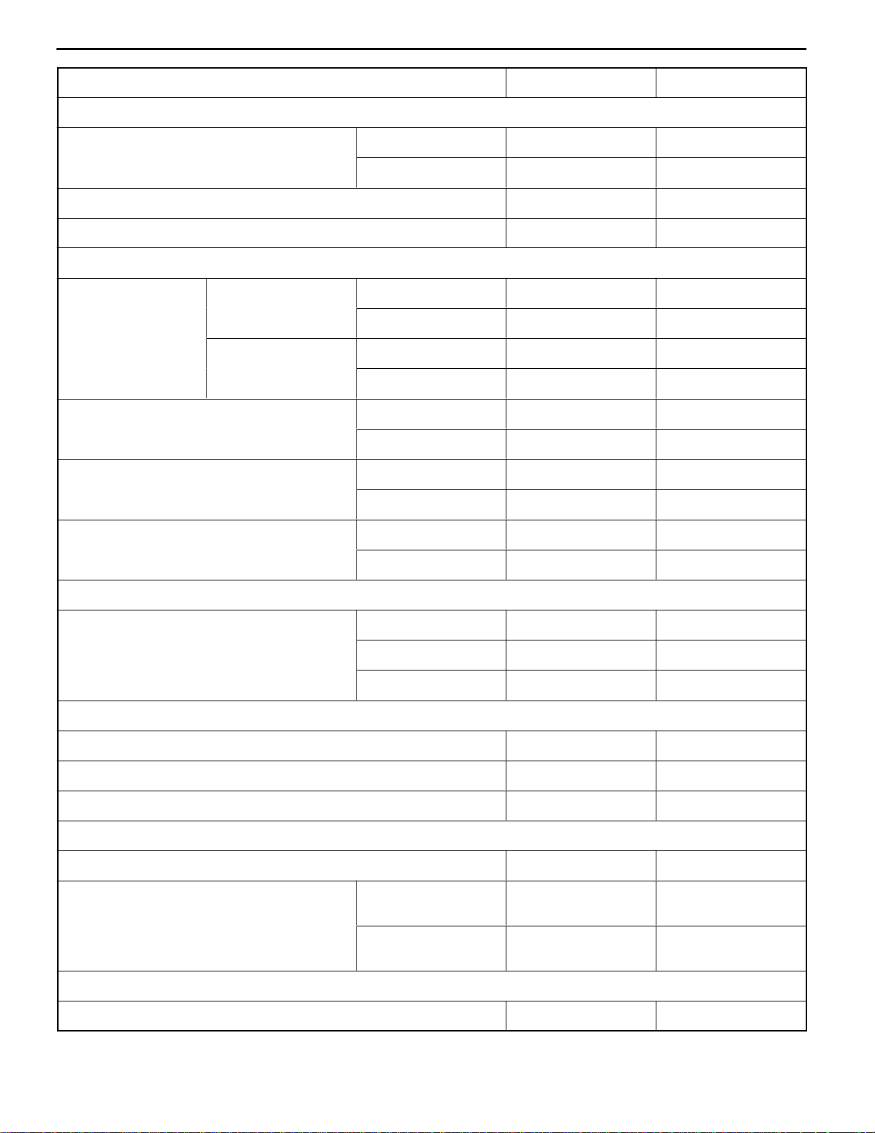
SERVICE SPECIFICATIONS
Item Standard Limit
Cylinder head
Flatness of cylinder head surface mm 0.05 -
Cylinder head gasket
11A-1-1
Gasket thickness
mm
Cylinder block
Cylinder diameter mm Class A 80.006 - 80.024 -
Pistons
Piston-to-cylinder clearance mm 0.021 - 0.055 -
Standard, class A 79.971 - 79.985 -
Standard, class B 80.221 - 80.235 -
Piston rings
Height mm Top 2.5 -
Projecting height of
piston - 0.073
Projecting height of
piston 0.073 - 0.206
Projecting height of
piston 0.206 -
Number of holes; 2 1.4 -
Number of holes; 1 1.5 -
Number of holes; 3 1.6 -
Class B 80.256 - 80.274 -
Bottom 2 -
Oil 3 -
Axial clearance in piston groove mm Top 0.030 - 0.065 -
Bottom 0.030 - 0.065 -
Oil 0.030 - 0.065 -
Fitted gap (in cylinder) mm To p 0.30 - 0.40 -
Bottom 0.25 - 0.40 -
Oil 0.25 - 0.50 -
Piston pin
Diameter mm 26 -
E
July 1996Mitsubishi Motors Corporation
PWEE9602
Page 8
11A-1-2
Item LimitStandard
Camshaft
Cam height Intake 8.5 -
Camshaft end play mm 0.048 - 0.133 -
Radial clearance mm 0.050 - 0.150 -
Valves
Valves clearance Checking Intake 0.15 - 0.25 mm
Adjusting Intake 0.2 -
V alve diameter mm Intake 36.22 -
F8QT ENGINE -
Exhaust 10.34 -
Exhaust 0.35 - 0.45 -
Exhaust 0.4 -
Exhaust 31.62 -
Specifications
V alve seat angle Intake 60_ -
Exhaust 45_ -
Valve seat width mm Intake 1.8 ± 0.2 -
Exhaust 1.8 -
Valve springs
Length mm Loading 0 N 43.9 -
Loading 250 N 36.8 -
Loading 612 N 26.4 -
Tappets
Diameter (tolerance) mm 35 -
Height mm 26.3 -
Clearance in cylinder block mm 0.025 - 0.075 -
Valve guides
Inside diameter mm 8 -
Outside diameter mm Standard
(no grooves)
Oversize 1
(two grooves)
Tappet pads
Thickness (increasing by increments of 0.05) mm 2.50 - 3.70 -
E
July 1996Mitsubishi Motors Corporation
PWEE9602
13 -
13.3 -
Page 9
F8QT ENGINE -
Item LimitStandard
Intermediate shaft
Inner bearing mm 39.5 -
Outer bearing mm 40.5 -
End play mm 0.07 - 0.15 -
Crankshaft
End play mm 0.07 - 0.23 -
Thrust washer thickness mm 2.30 - 2.50 -
Radial clearance (main bearings) mm 0.04 - 0.07 -
Main bearing journals
Ovality mm - 0.0025
Taper mm - 0.005
Diameter mm Standard (blue) 54.785 - 54.805 -
Specifications
11A-1-3
Standard (red) 54.795 - 54.805 -
Undersize 1 54.550 - 54.560 -
Big-end bearing journals
Ovality mm - 0.0025
Taper mm - 0.005
Diameter mm Standard 48.00 - 48.02 -
Undersize 1 47.75 - 47.77 -
Bearing recess width mm 20.25 - 20.95 -
Relative difference mm - 0.02
Connecting rod (big-end) bearings
Axial clearance mm 0.22 - 0.40 -
Radial clearance mm 0.031 - 0.075 -
Connecting rods
Length mm 144 ± 0.02 -
Small end inside diameter mm 26.013 - 26.025 -
Squareness, top/bottom mm - 0.04
Straightness mm - 0.1
E
July 1996Mitsubishi Motors Corporation
PWEE9602
Page 10
11A-1-4
Item LimitStandard
Flywheel
Axial throw measured at a radius of 80 mm mm - 0.07
Oil pump
End play mm 0.02 - 0.08 -
Clearance, gears to pump body (backlash) mm 0.10 - 0.24 -
Bearing clearance, drive shaft mm 0.024 - 0.49 -
Number of teeth on oil pump sprocket 8 -
Oil pressure regulator spring
Length mm Loading 0 N 74.6 -
Lubrication system
F8QT ENGINE -
Loading 10.2 N 48.2 -
Loading 70 N 41.2 -
Specifications
Oil capacity, exclusive of oil filter L 4.8 -
Oil capacity, inclusive of oil filter L 5.3 -
Difference between MAX-MIN marks on dipsitck L 1.7 -
Oil pressure with new filter and hot engine - 13 r/s (1,000 rpm) - 200
(min.) kPa
- 50 r/s (3,000 rpm) - 350
E
July 1996Mitsubishi Motors Corporation
PWEE9602
Page 11
F8QT ENGINE -
Specifications
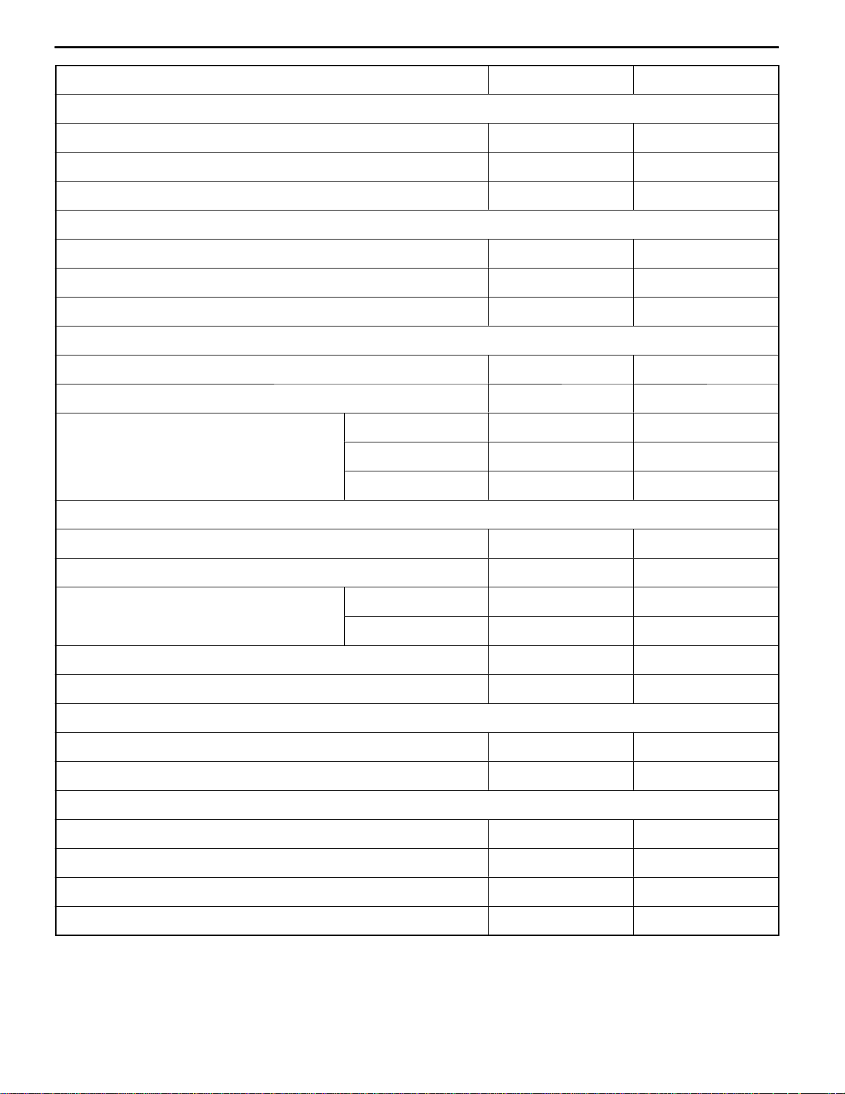
TORQUE SPECIFICATIONS
Items Nm
Crankshaft pulley
Crankshaft pulley bolt 120
Timing belt
Camshaft sprocket bolt 50
Water pump
Water pump pulley bolt 20
Water pump bolt 12.5
Thermostat
Thermostat cover bolt 10
Thermostat housing bolt 10
Bleedscrew 0.6
11A-1-5
Glow plugs
Glow plug 22.5
Glow plug nut 5
Turbocharger
Turbocharger nut 45
Exhaust downpipe connector nut 45
Oil supply pipe union nut 35
Oil return pipe union nut 25
Coolant supply pipe banjo bolt 25
Coolant supply pipe retaining nut 28.7
Coolant discharge pipe union nut 25
Coolant discharge pipe retaining nut 8
Intake and exhaust manifolds
EGR valve 19.5
EGR pipe 19.5
Oil pipe union nut 30
Oil pipe retaining nut 8
Manifold nut 25
E
July 1996Mitsubishi Motors Corporation
PWEE9602
Page 12
11A-1-6
Items Nm
Rocker cover and cylinder head
Rocker cover nut 5
Cylinder head bolt 30 + 50_ ± 4_ + fully slacken + 25 + 213_ ± 2_
Camshaft, intake and exhaust valves
Camshaft bearing cap bolt (M6) 10
Camshaft bearing cap bolt (M8) 20
Glow plug 22.5
Fuel injection nozzle 70
Vacuum pump
V acuum pump bolt 22
Vacuum hose union nut 22
F8QT ENGINE -
Specifications
+ (warm up) 120_ ± 7_
Oil cooler and oil filter
Thermostat housing nut 60
Plug 35
Oil cooler nut 60
Oil pan, oil pump and oil jets
Oil drain plug 15
Oil pan bolt 13
Oil pump cover bolt 12
Oil pump body bolt 22
Oil jet 20
Intermediate shaft and intermediate shaft bearings
Intermediate shaft sprocket bolt 50
Intermediate shaft cover bolt 15
Intermediate shaft lockplate bolt 15
Cover bolt 15
Fuel injection nozzle
Injection pipe union nut 22.5
Nozzle body 70
Retaining nut 70
E
July 1996Mitsubishi Motors Corporation
PWEE9602
Page 13
F8QT ENGINE -
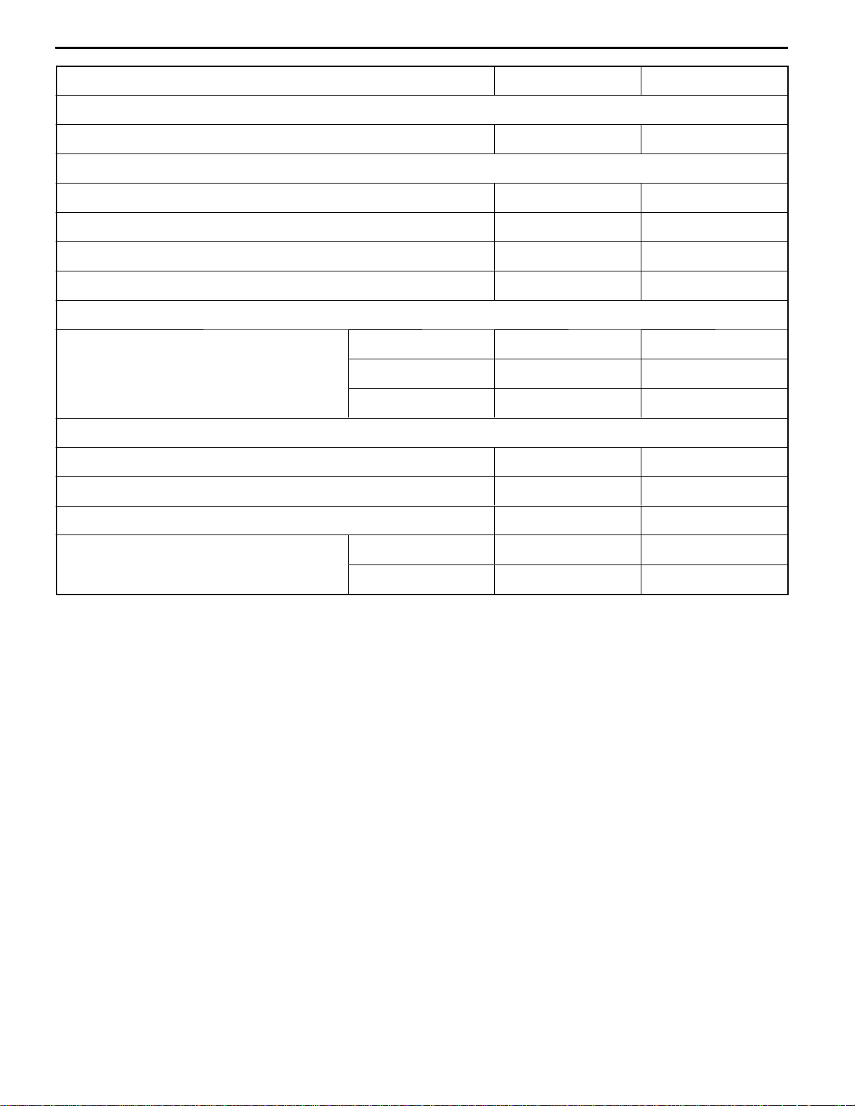
Items Nm
Fuel injection pump
Injection pipe union nut 22.5
Screwed sleeve/nut assembly 90
Nut 70
Injection pump bolt 22.5
Bolt 20
Pistons and connecting rods
Connecting rod cap bolt 45
Flywheel
Flywheel bolt 53
Crankshaft and cylinder block
Main bearing cap bolt 65
Specifications
11A-1-7
Front plate bolt 12.5
E
July 1996Mitsubishi Motors Corporation
PWEE9602
Page 14

11A-1-8
F8QT ENGINE -
Specifications
FORM-IN-PLACE GASKET
The engine has several areas where the form-in-place gasket (FIPG) is in use. To ensure that the gasket
fully serves its purpose, it is necessary to observe some precautions when applying the gasket. Bead
size, continuity and location are of paramount importance. Too thin a bead could cause leaks. Too thick
a bead, on the other hand, could be squeezed out of location, causing blocking or narrowing of the
fluid feed line. To eliminate the possibly of leaks from a joint, therefore, it is absolutely necessary to
apply the gasket evenly without a break, while observing the correct bead size.
The FIPG used in the engine is a room temperature vulcanization (RTV) type. Since the RTV hardens
as it reacts with the moisture in the atmospheric air, it is normally used in the metallic flange areas.
Disassembly
The parts assembled with the FIPG can be easily disassembled without use of a special method. In
some cases, however, the sealant between the joined surfaces may have to be broken by lightly striking
with a mallet or similar tool. A flat and thin gasket scraper may be lightly hammered in between the
joined surfaces. In this case, however, care must be taken to prevent damage to the joined surfaces.
For removal of the oil pan, the special tool “Oil Pan Remover” is available. Be sure to use the special
tool to remove the oil pan.
Surface Preparation
Thoroughly remove all substances deposited on the gasket application surfaces, using a gasket scraper
or wire brush. Check to ensure that the surfaces to which the FIPG is to be applied is flat. Make sure
that there are no oils, greases and foreign substances deposited on the application surfaces. Do not
forget to remove the old sealant remained in the bolt holes.
Form-In-Place Gasket Application
When assembling parts with the FIPG, you must observe some precautions, bu t the procedures is very
simple as in the case of a conventional precut gasket.
Applied FIPG bead should be of the specified size and without breaks. Also be sure to encircle the
bolt hole circumference with a completely continuous bead. The FIPG can be wiped away unless it is
hardened. While the FIPG is still moist (in less than 15 minutes), mount the parts in position. When
the parts are mounted, make sure that the gasket is applied to the required area only. In addition, do
not apply any oil or water to the sealing locations or start the engine until a sufficient amount of time
(about one hour) has passed after installation is completed.
The FIPG applications procedure may vary on different areas. Observe the procedure described in the
text when applying the FIPG.
E
July 1996Mitsubishi Motors Corporation
PWEE9602
Page 15
F8QT ENGINE -
Special Tools
2. SPECIAL TOOLS
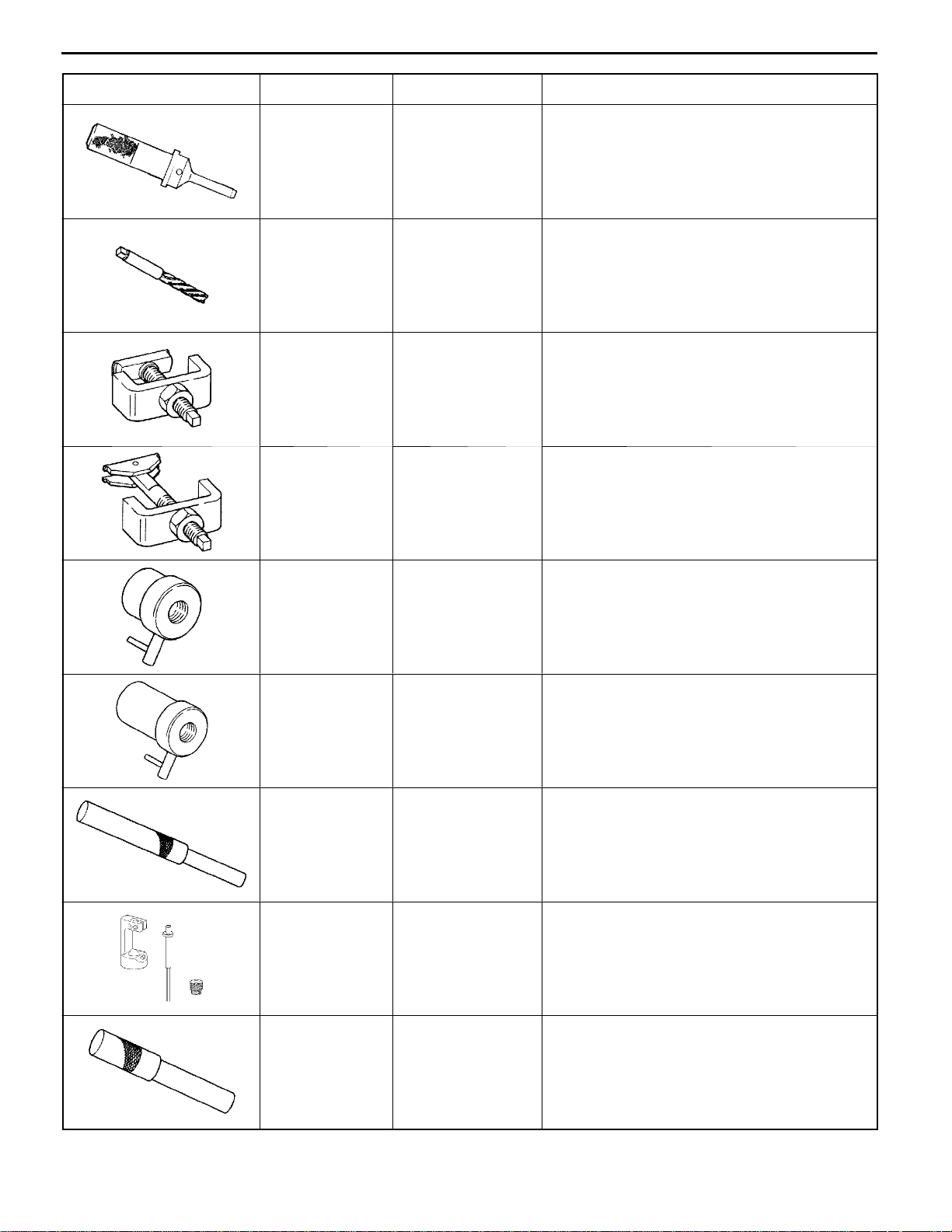
Tool Number Name Use
11A-2-1
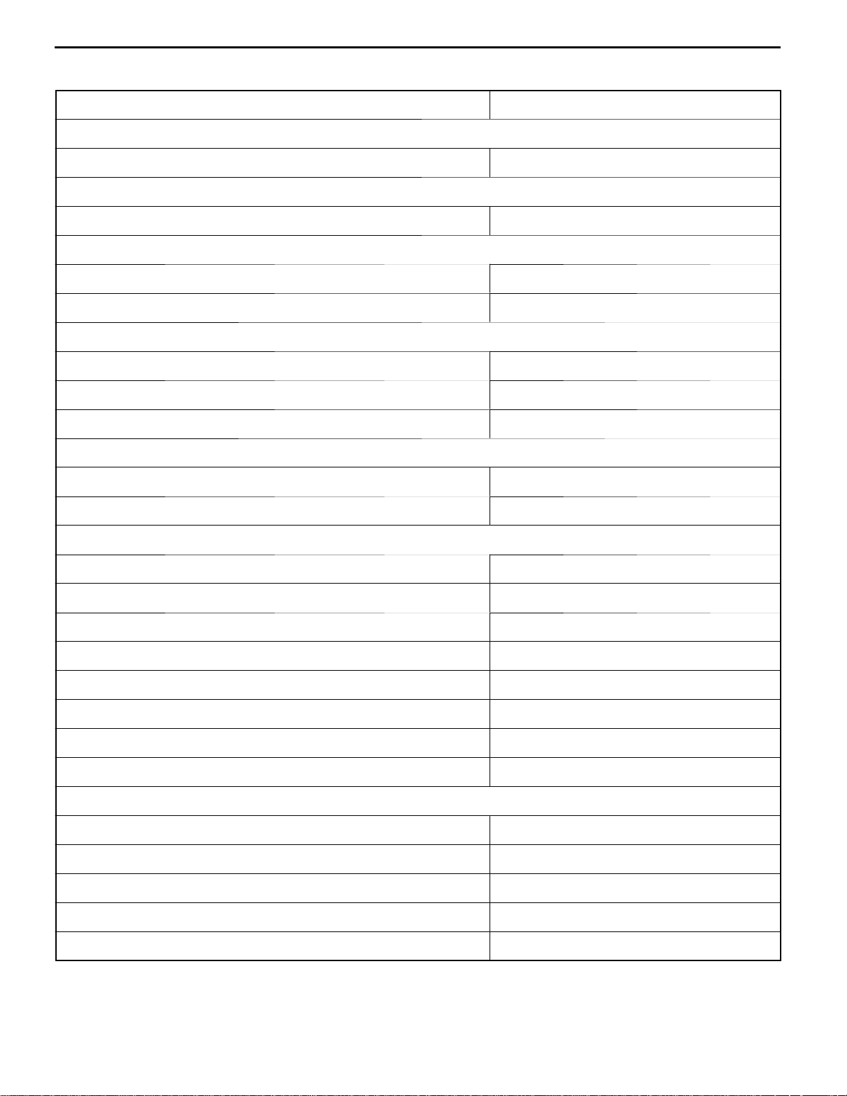
MB990767 Camshaft sprocket
holder
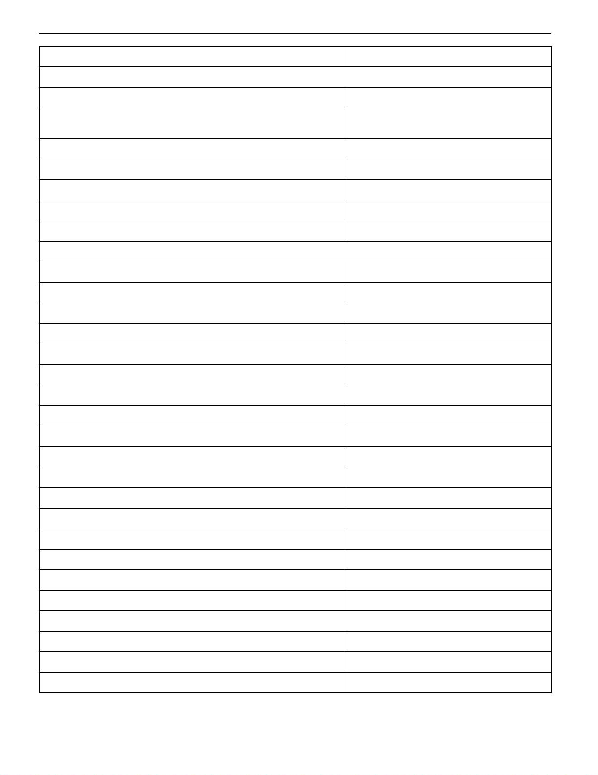
MB991614 Angle gauge Tightening cylinder head bolts
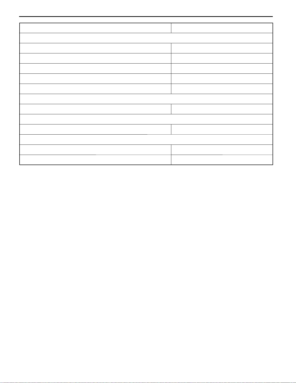
MB996014 Valve spring
compressor
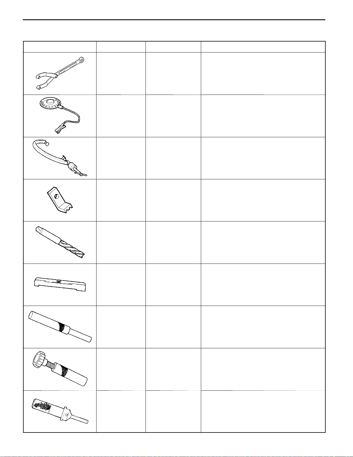
MB996015 Flywheel stopper Locking the flywheel
Removal of camshaft sprocket
Removal of valve spring split cones
MB996016 Reamer Reaming valve guides
MB996018 Slip gauge Measuring the crankshaft end play
MB996020 Valve guide
remover
MB996021 Valve stem seal
remover
Pressing in valve guides
Removal of valve guide seal
MB996022 Valve seat installer Pressing in intake valve seat
E
July 1996Mitsubishi Motors Corporation
PWEE9602
Page 16
11A-2-2
Tool UseNameNumber
MB996023 Valve seat installer Pressing in intake valve seat
MB996024 Reamer Reaming valve guides
MB996025 Bearing puller Removal of intermediate shaft outer bearing
MB996026 Bearing puller Removal of intermediate shaft inner bearing
F8QT ENGINE -
Special Tools
MB996027 Bearing installer Installation of intermediate shaft inner bearing
MB996028 Bearing installer Installation of intermediate shaft outer bearing
MB996029 Valve guide
installer
MB996030 Measuring device
adapter
Pressing in valve guides
Adjustment of fuel injection pump
MB996031 Valve stem seal
installer
E
July 1996Mitsubishi Motors Corporation
PWEE9602
Installation of valve guide seal
Page 17
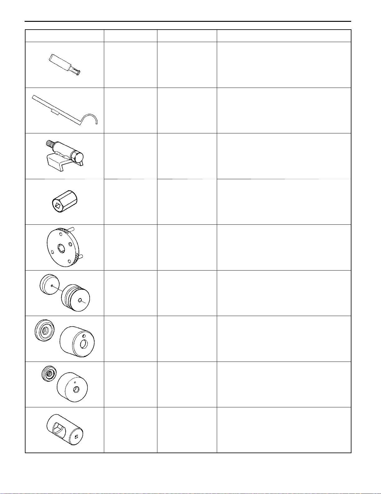
Tool UseNameNumber
MB996032 Tension gauge Measuring timing belt deflection
MB996033 Tension gauge Measuring timing belt deflection
MB996034 Sprocket stopper Removal of intermediate shaft sprocket
MB996036 Hexagon socket Removal of injection pump sprocket screwed
F8QT ENGINE -
Special Tools
sleeve/nut assembly
11A-2-3
MB996037 Sprocket adapter Adjustment of fuel injection pump
MB996038 Oil seal installer Installation of crankshaft oil seal (flywheel end)
MB996039 Oil seal installer Installation of intermediate shaft oil seal
MB996040 Oil seal installer Installation of crankshaft oil seal (timing gear
end)
MB996041 Special socket Removal of fuel injectors
E
July 1996Mitsubishi Motors Corporation
PWEE9602
Page 18
11A-2-4
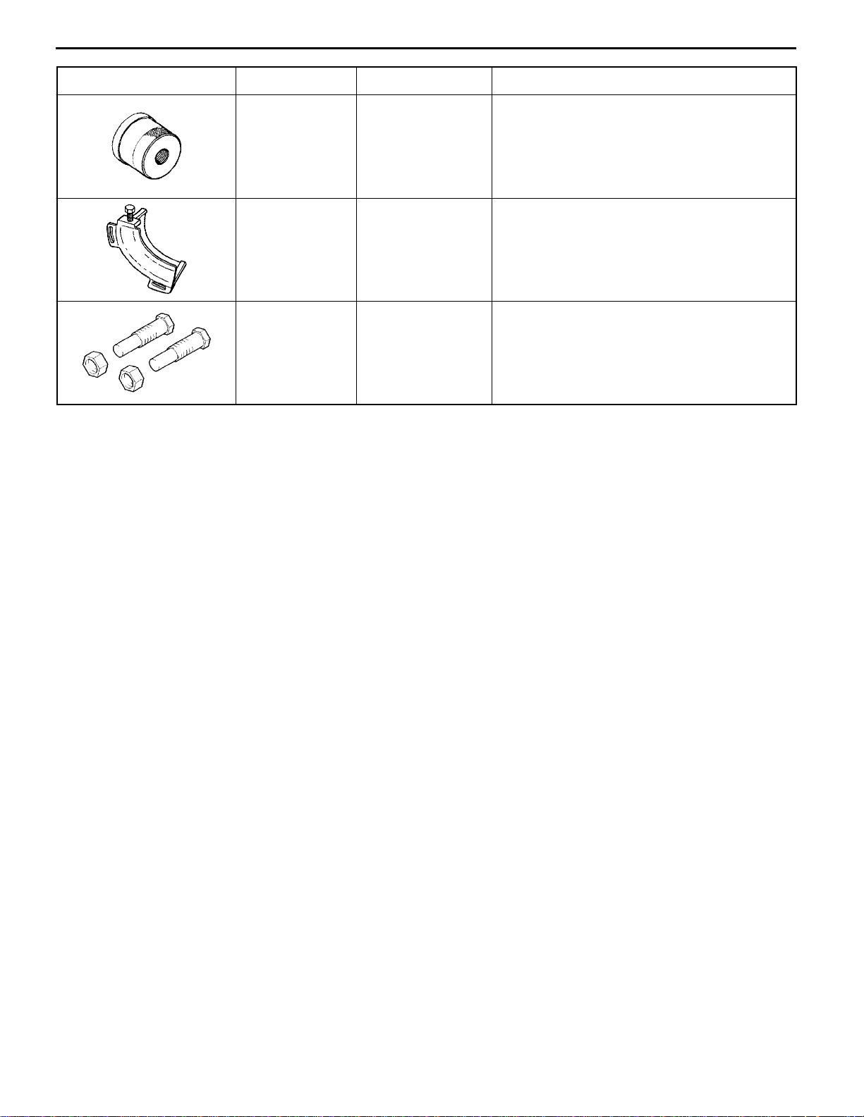
Tool UseNameNumber
MB996042 Oil seal installer Installation of camshaft oil seal
MB996043 Sprocket stopper Locking the injection pump sprocket
MD998715 Pulley holder pin Retaining the camshaft sprocket (use together
F8QT ENGINE -
Special Tools
with MB990767)
E
July 1996Mitsubishi Motors Corporation
PWEE9602
Page 19
F8QT ENGINE -
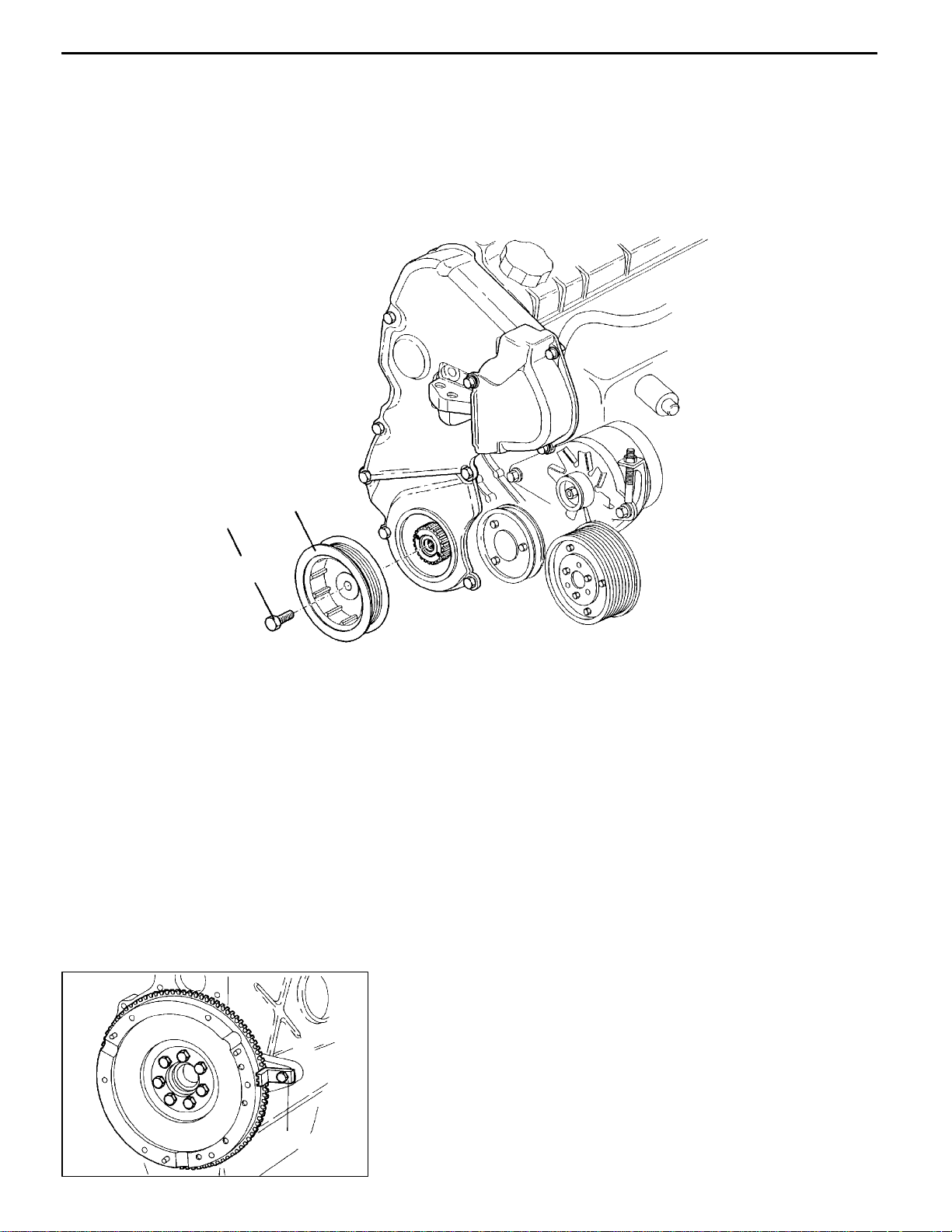
3. CRANKSHAFT PULLEY
Crankshaft Pulley
11A-3-1
120 Nm
2
1
Removal steps
AA""AA 1. Crankshaft pulley bolt
2. Crankshaft pulley
REN0143
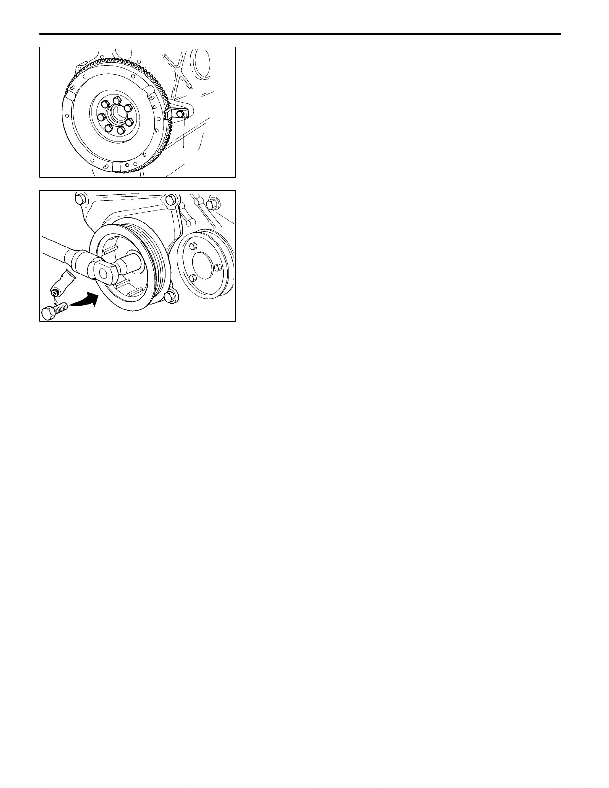
REMOVAL SERVICE POINT
AA"
Use special tool MB996015 to hold the flywheel during
removal.
MB996015
REN0144
E
July 1996Mitsubishi Motors Corporation
CRANKSHAFT PULLEY BOLT REMOVAL
PWEE9602
Page 20
11A-3-2
F8QT ENGINE -
MB996015
REN0144
Crankshaft Pulley
INSTALLATION SERVICE POINT
"AA
(1) Use special tool MB996015 to hold the flywheel during
(2) Apply a locking agent to the screw thread of the bolt.
CRANKSHAFT PULLEY INSTALLATION
installation.
Tighten the bolt to the specified torque.
REN0145
E
July 1996Mitsubishi Motors Corporation
PWEE9602
Page 21
F8QT ENGINE -
4. TIMING BELT
REMOVAL AND INSTALLATION
Timing Belt
11A-4-1
12
50 Nm
10
11
9
8
13
REN0001
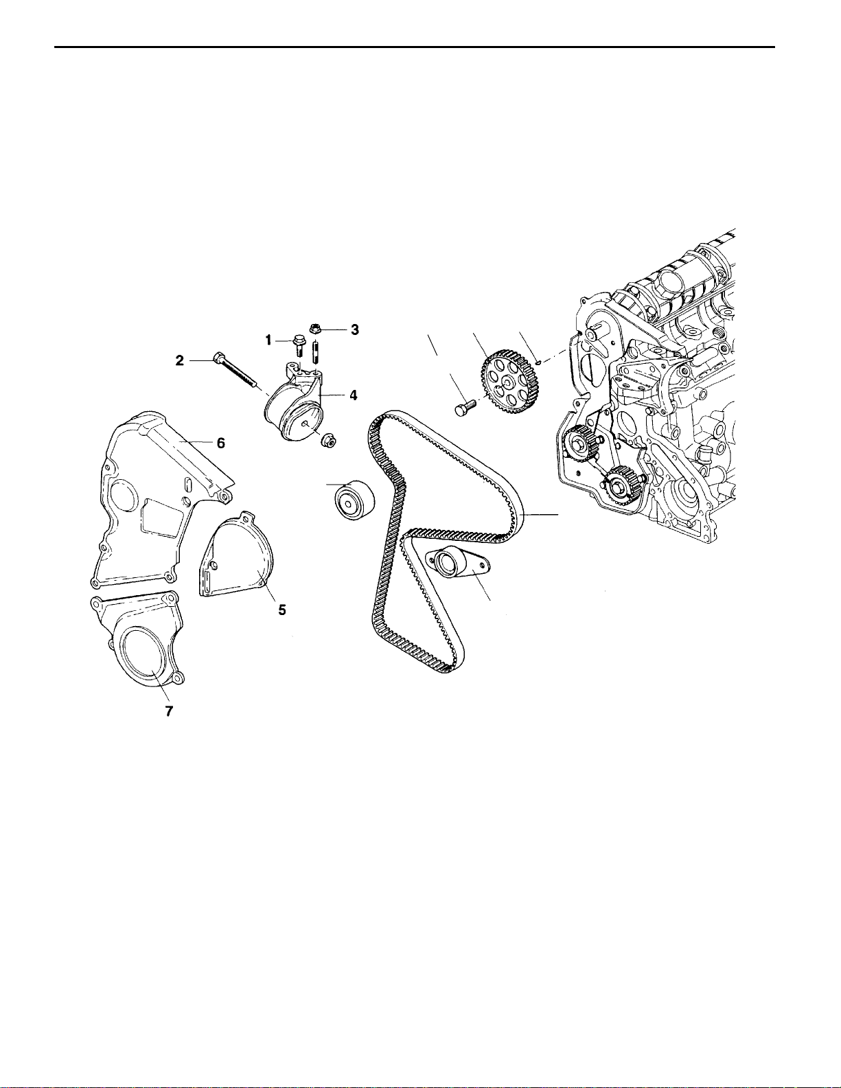
Removal steps
1. Bolt
2. Bolt
3. Nut
4. Engine support bracket
5. Timing gear case cover
6. Timing gear case cover
7. Timing gear case cover
E
July 1996Mitsubishi Motors Corporation
PWEE9602
AA""BA
AB""AA
8. Timing belt
9. Camshaft sprocket bolt
10. Camshaft sprocket
11. Camshaft sprocket key
12. Timing belt tensioner
13. Timing belt idler
Page 22
11A-4-2
REN0002
F8QT ENGINE -
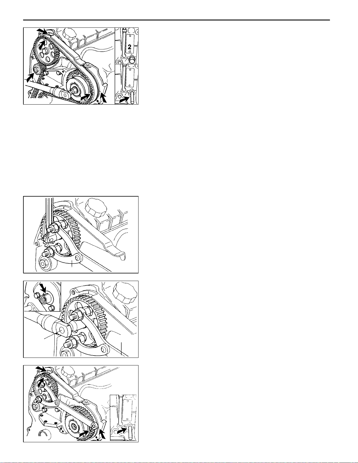
REMOVAL SERVICE POINTS
AA"
(1) Turn the crankshaft clockwise so that the piston of No.
(2) Insert an 8 mm diameter locking pin in the threaded hole
(3) Slacken the lock nut of the timing belt tensioner.
TIMING BELT REMOVAL
1 cylinder (flywheel end) is at TDC, with the following
marks in line with each other:
D flywheel/clutch housing;
D rear guard plate/camshaft sprocket.
Scribe a mark on the injection pump mounting bracket.
of torx bolt2so that it engages the recess in the crankshaft
web.
Remove the timing belt.
Timing Belt
50 Nm
REN0004
MB990767
REN0003
MB990767
AB"
CAMSHAFT SPROCKET BOLT REMOVAL
(1) Use special tool MB990767, camshaft sprocket holder
with pin MD998715 and remove the retaining bolt.
INSTALLATION SERVICE POINTS
"AA
(1) Smear the retaining bolt with a locking agent.
"BA
(1) Turn the camshaft clockwise with special tool MB990767
(2) Turn the crankshaft 1/4 revolution counter-clockwise from
(3) Align the mark on the injection pump sprocket with the
CAMSHAFT SPROCKET BOLT INSTALLATION
Use special tool MB990767, camshaft sprocket holder
with pin MD998715 to stop the sprocket turning and then
tighten the camshaft sprocket retaining bolt to 50 Nm.
TIMING BELT INSTALLATION
until the mark on the camshaft sprocket is opposite the
mark on the guard plate.
the TDC position of No. 1 cylinder and insert the 8 mm
diameter locking pin in the recess in the crankshaft web.
mark on th e mounting bracket (turn clockwise).
REN0005
E
July 1996Mitsubishi Motors Corporation
PWEE9602
Page 23
REN0006
MB996032
MB996033
F8QT ENGINE -
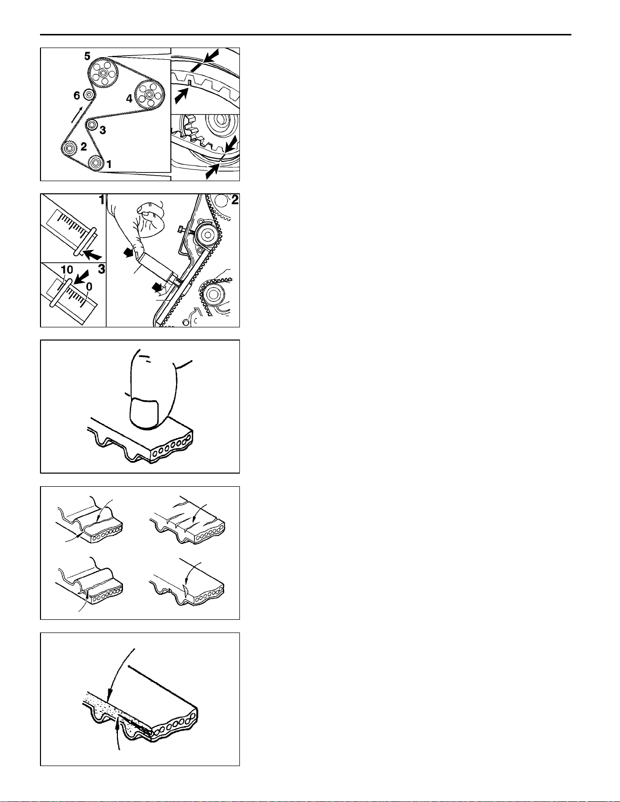
(4) Fit the timing belt so that the lines on the belt are aligned
with the marks on t h e crankshaft and camshaft sprockets
and the injection pump sprocket.
NOTE
D the direction of rotation of th e belt (see the arrows
on the belt);
D the sequence in which the belt is fitted around the
sprockets.
(5) Fit the special tool on the timing belt and the timing belt
tensioner.
(6) Tension the timing belt with the aid of an M6 bolt.
Standard value: 7 .5 mm
(7) Tighten the lock nut to the specified torque.
Timing Belt
11A-4-3
REN0007
INSPECTION
TIMING BELT
Should either of the following defects be evident, replace
the belt with a new one:
(1) Hardened back surface rubber.
Glossy, non-elastic and so hard that no mark is produced
when scratched with a fingernail.
8EN0066
3
4
2
5
8EN0044
(2) Cracked back surface rubber.
(3) Cracked or separated canvas.
(4) Cracked tooth bottom.
(5) Cracks in back surface of belt.
(6) Abnormal wear on the sides of the belt. A normal belt
should have clear-cut sides as if cut by a sharp knife.
8EN0067
E
July 1996Mitsubishi Motors Corporation
PWEE9602
Page 24

11A-4-4
F8QT ENGINE -
(7) Abnormal wear in teeth.
(8) Missing tooth.
8EN0068
TIMING BELT TENSIONER AND IDLER
(1) Check that the tensioner and idler rotate smoothly without
excessive play or abnormal noise. Replace them with
new ones if necessary.
Timing Belt
REN0008
E
July 1996Mitsubishi Motors Corporation
PWEE9602
Page 25

F8QT ENGINE -
5. WATER PUMP
REMOVAL AND INSTALLATION
Water Pump
11A-5-1
12.5 Nm
20 Nm
Removal steps
1. V-ribbed belt (alternator & others)
2. Bolt
3. Water pump pulley
4. Bolt
5. Water pump
6. Water pump gasket
E
July 1996Mitsubishi Motors Corporation
PWEE9602
REN0009
Page 26

F8QT ENGINE -
6. THERMOSTAT
REMOVAL AND INSTALLATION
0.6 Nm
Thermostat
10 Nm
11A-6-1
10 Nm
"AA
"AA
Removal steps
1. Bolt
2. Thermostat cover
3. Plate
4. O-ring
5. Thermostat
6. Bolt
7. Thermostat housing
8. O-ring
9. Bleedscrew
REN0010
INSTALLATION SERVICE POINT
"AA
Caution
D
O-RING INSTALLATION
If O-rings are soaked in engine oil they will swell
up. Keep the O-rings 4 and 8 free of engine oil when
they are being fitted.
E
July 1996Mitsubishi Motors Corporation
PWEE9602
Page 27

F8QT ENGINE -
7. WATER HOSES AND PIPES
REMOVAL AND INSTALLATION
Water Hoses and Pipes
11A-7-1
REN0035
Removal steps
1. Water inlet hose
2. Water outlet hose
3. Heater inlet hose
4. Heater outlet hose
E
July 1996Mitsubishi Motors Corporation
PWEE9602
Page 28

F8QT ENGINE -
Engine Coolant Temperature Sensor
8. ENGINE COOLANT TEMPERATURE SENSOR
REMOVAL AND INSTALLATION
11A-8-1
REN0036
Removal steps
1. Wiring harness connector
2. Retaining clip
3. Temperature sensor, ECU
4. Temperature sensor, instrument
panel
E
July 1996Mitsubishi Motors Corporation
PWEE9602
Page 29
F8QT ENGINE -
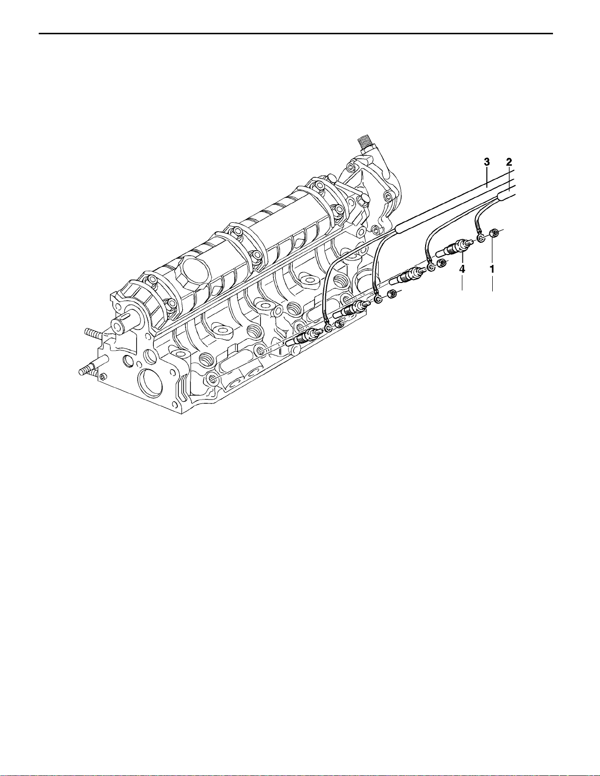
9. GLOW PLUGS
REMOVAL AND INSTALLATION
Glow Plugs
11A-9-1
Removal steps
1. Nut
2. Glow plug leads, Nos. 1 and 2
3. Glow plug leads, Nos. 3 and 4
4. Glow plug
22.5 Nm
5Nm
REN0037
E
July 1996Mitsubishi Motors Corporation
PWEE9602
Page 30

F8QT ENGINE -
10. TURBOCHARGER
REMOVAL AND INSTALLATION
35 Nm
25 Nm
45 Nm
Turbocharger
28.7 Nm
11A-10-1
45 Nm
Removal steps
1. Vacuum hose
2. Oil supply pipe
3. Oil return pipe
4. Nut
5. Banjo bolt
6. Coolant supply pipe
25 Nm
25 Nm
8Nm
"AA
REN0038
7. Union nut
8. Coolant discharge pipe
9. Connector-to-exhaust downpipe
10. Nut
11. Turbocharger unit
INSTALLATION SERVICE POINTS
"AA
(1) Before fitting the turbocharger lubricate the parts with
E
July 1996Mitsubishi Motors Corporation
TURBOCHARGER INSTALLATION
engine oil introduced through oil filler opening.
PWEE9602
Page 31

F8QT ENGINE -
Intake and Exhaust Manifolds
11. INTAKE AND EXHAUST MANIFOLDS
REMOVAL AND INSTALLATION
19.5 Nm
19.5 Nm
11A-11-1
30 Nm
8Nm
25 Nm
REN0039
Removal steps
1. Vacuum hose
2. EGR valve
3. EGR pipe
4. Oil pipe from turbocharger
5. Vacuum hose to turbocharger
E
July 1996Mitsubishi Motors Corporation
PWEE9602
6. Engine hanger
7. Bracket
8. Nuts
9. Intake and exhaust manifolds
10. Gasket
Page 32

F8QT ENGINE -
Rocker Cover and Cylinder Head
12. ROCKER COVER AND CYLINDER HEAD
REMOVAL AND INSTALLATION
5Nm
11A-12-1
REN0040
Removal steps
1. Engine hanger
2. Thermostat housing
3. Vacuum pump
4. Oil filler cap
5. Nut
6. Rocker cover
"DA
E
7. Rocker cover gasket
July 1996Mitsubishi Motors Corporation
PWEE9602
AA""BA
AB""AA
"CA
8. Cylinder head bolt
9. Washer
10. Cylinder head
11. Cylinder head gasket
A: Locating dowel
Page 33

11A-12-2
F8QT ENGINE -
REN0041
Rocker Cover and Cylinder Head
REMOVAL SERVICE POINTS
AA"
(1) Release and then remove the cylinder head bolts.
(2) Lift the cylinder head straight up over the locating dowels
CYLINDER HEAD REMOVAL
and then remove the cylinder head.
REN0042
AB"
CYLINDER HEAD GASKET REMOVAL
Caution
D
When removing the cylinder head gasket, take care
not to scratch the cylinder head or cylinder block
gasket faces.
INSTALLATION SERVICE POINTS
"AA
(1) Select a cylinder head gasket of the correct thickness
CYLINDER HEAD GASKET INSTALLATION
according to the projecting height of the pistons. The
available cylinder head gaskets are shown in the table
below. The thickness of the gasket is indicated by the
number of holes near the end of the gasket (see the
illustration). Measure the projecting height of the pistons
and calculate the average height. Then select a cylinder
head gasket of the correct thickness from the table shown
below.
Piston height
above cylinder
block mm
- 0.073 2 1.40
0.073 - 0.206 1 1.50
0.206 - 3 1.60
Number of holes Gasket thickness
mm
When only the gasket is to be replaced, check the hole
pattern on the old gasket and select a gasket with the
same number of holes.
Caution
D
If a piston or connecting rod, etc. has been
replaced, always measure the projecting height
of the pistons because this may have changed
after replacing these parts.
E
July 1996Mitsubishi Motors Corporation
PWEE9602
Page 34
F8QT ENGINE -
Rocker Cover and Cylinder Head
11A-12-3
120.5
120.5
>
MB991614
REN0043
REN0044
"BA
CYLINDER HEAD INSTALLATION
(1) Select a suitable cylinder head gasket11.
(2) Rotate the crankshaft so that the piston of No. 1 cylinder
is positioned a quarter-stroke past TDC.
(3) Fit the cylinder head over the locating dowels.
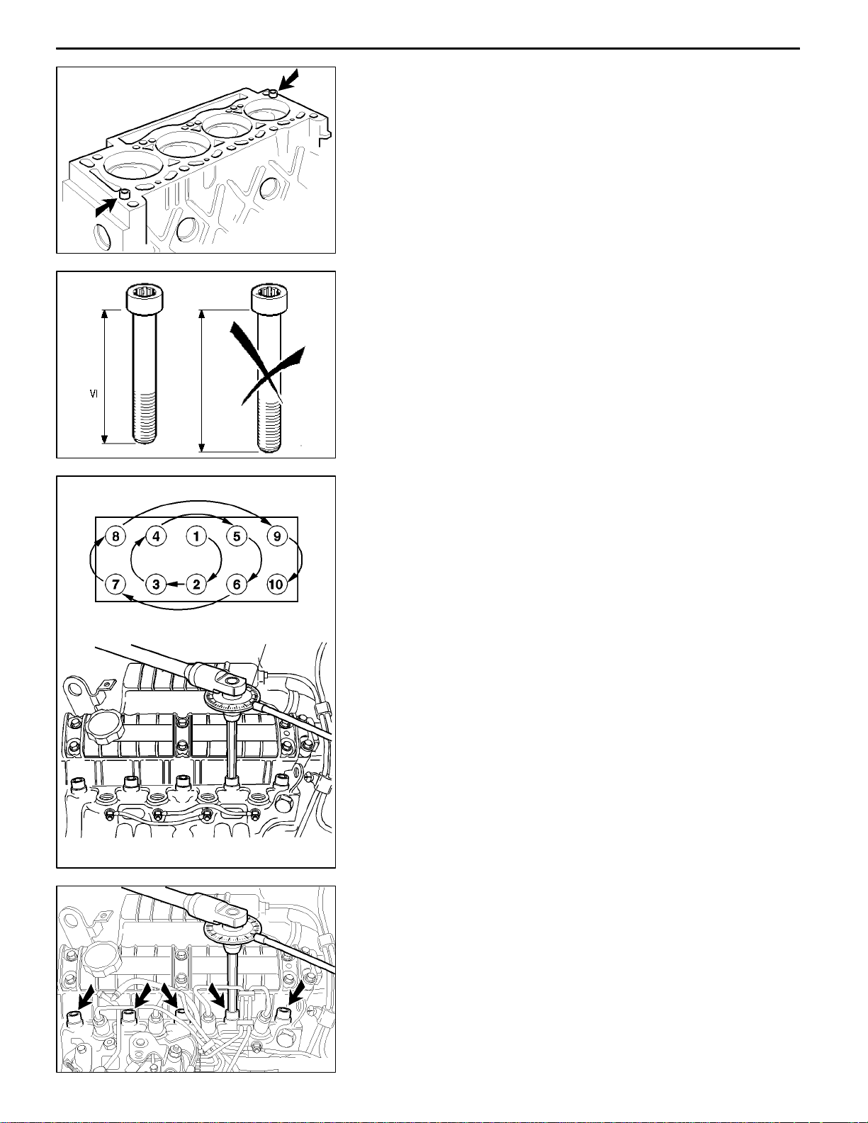
"CA
CYLINDER HEAD BOLT INSTALLATION
(1) When installing the cylinder head bolts, check that the
length of the shank of each bolt (without the washer)
is within the limit value. All the cylinder head bolts must
be renewed as soon as any of them exceeds the permitted
length.
Limit: max. 120.5 mm
(2) Fit the washers.
(3) Lubricate the bolt threads and washers with engine oil.
(4) Insert the cylinder head bolts and fasten them finger-tight.
The cylinder head bolts should be torque-tightened in
three stages.
Tighten in the first stage:
D first to 30 Nm;
D then angle-tighten to 50_ ± 4_ in a single uninterrupted
movement.
NOTE
Wait at least three minutes to allow the head gasket to
bed down properly.
(5) Now slacken all the bolts completely.
(6) Then tighten to the second stage torque:
D first to 25 Nm;
D then angle-tighten the bolts to 213_ ± 7_ in a single
uninterrupted movement.
REN0045
(7) The cylinder head can only be retorqued after letting
the engine warm up to its operating temperature.
Tightening torque for the third stage:
D let the engine warm up (engine cooling fan starts
to turn);
D then angle-tighten the cylinder head bolts to 120_
± 7_ in a single uninterrupted movement.
REN0046
E
July 1996Mitsubishi Motors Corporation
PWEE9602
Page 35

11A-12-4
F8QT ENGINE -
Rocker Cover and Cylinder Head
REN0047
"DA
ROCKER COVER GASKET INSTALLATION
(1) Lightly smear the corners of the rocker cover gasket with
a sealant.
(2) Locate the gasket on the rocker cover.
(3) Fit the rocker cover.
Caution
D
Make sure the gasket is still properly located.
E
July 1996Mitsubishi Motors Corporation
PWEE9602
Page 36

F8QT ENGINE -
Camshaft, Intake and Exhaust Valves
13. CAMSHAFT, INTAKE AND EXHAUST VALVES
REMOVAL AND INSTALLATION
10 Nm
20 Nm
11A-13-1
Lubricate all
internal parts
with engine oil
during reassembly.
"FA
"FA
"FA
"FA
"FA
"HA
AA""EA
AB""DA
E
Removal steps
1. Bolt
2. No. 1 camshaft bearing cap
3. No. 2 camshaft bearing cap
4. No. 3 camshaft bearing cap
5. No. 4 camshaft bearing cap
6. No. 5 camshaft bearing cap
7. Camshaft
8. Oil seal
9. Tappet pad
10. Tappet
11. Retainer locks
12. Valve spring retainer
13. Valve spring
14. Valve spring collar
15. Valve stem seal
16. Intake valve
July 1996Mitsubishi Motors Corporation
PWEE9602
AC""CA
AC""CA
AD""BA
AD""BA
AE""GA
"AA
"AA
"AA
70 Nm
22.5 Nm
REN0048
17. Exhaust valve
18. Glow plug
19. Injection nozzle
20. Shield
21. Water pipe
22. Intake valve guide
23. Exhaust valve guide
24. Intake valve seat
25. Exhaust valve seat
26. Swirl camber
27. Stud
28. Sealing plug
29. Sealing plug
30. Sealing plug
31. Cylinder head
Page 37

11A-13-2
MB996014
F8QT ENGINE -
REN0049
Camshaft, Intake and Exhaust Valves
REMOVAL SERVICE POINTS
AA"
(1) Fit valve spring compressor MB996014 on the cylinder
(2) Press down the valve spring retainer12and remove t he
RETAINER LOCKS REMOVAL
head
as shown in the illustration.
31
retainer locks11.
MB996021
MB996020
REN0050
REN0051
AB"
VALVE STEM SEAL REMOVAL
Remove the seal15with valve stem seal remover MB996021.
AC"
VALVE GUIDE REMOVAL
(1) Support the cylinder head31.
(2) Press out the valve guides
23, 23
towards the valve seat
with valve guide remover MB996020.
AD"
(1) Cut two recesses in the valve seats
VALVE SEAT REMOVAL
24, 25
. The recesses
are cut in order to lower the tension in the valve seat.
REN0052
(2) Break the valve seat into pieces with the aid of a cold
chisel.
REN0053
E
July 1996Mitsubishi Motors Corporation
PWEE9602
Page 38

F8QT ENGINE -
REN0054
Camshaft, Intake and Exhaust Valves
11A-13-3
(3) Tap the valve seat through the passage and out of the
cylinder head using a long drift.
REN0055
REN0056
AE"
SWIRL CHAMBER REMOVAL
(1) Insert a round rod in the glow plug hole. Remove the
swirl chamber by tapping the rod with a hammer.
INSPECTION
CAMSHAFT
End play
(1) Measure the end play. Fit a new cylinder head if the
measured value deviates from th e specified value.
Difference between cam height and base circle
diameter
(1) Fit a new camshaft7if the limit value is exceeded.
: Cam height
A
: Base circle diameter
B
REN0057
E
Radial play
(1) Support the camshaft7at No. 1 journalCand No. 5
journalDand measure the warp at No. 3 journalE.
Fit a new camshaft if the limit value is exceeded.
NOTE
The true warp is half of the value indicated by the dial
indicator when the camshaft7is rotated once.
REN0058
July 1996Mitsubishi Motors Corporation
PWEE9602
Page 39

11A-13-4
16, 17
F8QT ENGINE -
4ME0122
Camshaft, Intake and Exhaust Valves
INTAKE AND EXHAUST VALVES
Examining the valve stem for wear
(1) Replace the valve if the valve stem diameter is smaller
than the limit value or if there is evidence of uneven
wear.
NOTE
If the valve
16, 17
the valve seat
Valve seat angle and valve seat margin
(1) Replace t he valve
after correcting the valve seat angle.
: Valve seat angle.
A
: Valve seat margin.
B
is new, it should be matched with
24, 25
by grinding them together.
16, 17
if the limit value is exceeded
A
B
4ME0123
VALVE AND VALVE GUIDE
(1) Replace the part in question if the clearance exceeds
the limit value.
REN0059
VALVE AND VALVE SEAT
(1) Smear a layer of Minium evenly on the valve seating
A surface of the valve seats
(2) Press the valve
, making sure that the valve does not rotate.
25
: Grinding tool.
B
16, 17
24, 25
once against the valve seat
.
24,
NOTE
Before checking the valve contact, examine the valve
REN0060
16, 17
and the valve guide
22, 23
whether their condition is normal.
carefully to check
(3) Determine the condition of the valve seat by means of
the Minium pattern on the valve
16,17
. If abnormal contact
is established, take the following measures:
Small deviation: Grind the valve so that better contact
is obtained.
Large deviation: Correct or replace the valve and valve
seat.
4ME0126
E
July 1996Mitsubishi Motors Corporation
PWEE9602
Page 40

F8QT ENGINE -
Camshaft, Intake and Exhaust Valves
11A-13-5
VALVE SEAT
A
B
D
Valve seat width
(1) Replace the valve seat
24,25
if the limit value isexceeded.
AngleA: intake valve seat: 60_
exhaust valve seat: 45_
C
The contact surfaceBmust be 1.7
± 0.1 mm.
If the contact surface is too wide, correct this with a valve
seat cutter.
REN0061
Cutter angle:
AngleC: intake valve seat: 45_
exhaust valve seat: 30_
Caution
D
The outside diameter of the cutter for the valve
seat must not be more than:
intake valve seat: 37.0 mm
exhaust valve seat: 32.1 mm
After cutting, the dimensionDmust be 0.125
± 0.025
mm.
NOTE
After correcting or replacing the valve seat
valve seat and the valve
16, 17
should be matched by
24, 25
, the
grinding them together in order to obtain correct seating.
CYLINDER HEAD
(1) Check the cylinder head gasket surface31for distortion.
Fit a new cylinder head if the limit value is exceeded.
REN0062
CORRECTION
INTAKE VALVE AND EXHAUST VALVE
Caution
D
The amount of material removed by grinding should
be restricted to a minimum.
D
Replace the valve 16, 17 if the margin of the valve
seat after grinding is smaller than the limit value.
D
After the grinding operation, the valve 16, 17 should
be matched with the valve seat 24, 25 by lapping
4ME0130
E
July 1996Mitsubishi Motors Corporation
them together in order to obtain correct seating.
PWEE9602
Page 41

11A-13-6
F8QT ENGINE -
16, 17
C
A
4ME0131
REN0063
Camshaft, Intake and Exhaust Valves
VALVE AND VALVE SEAT
(1) The valve and the valve seat must be lapped as follows:
(a) Smear a thin layer of lapping compound evenly on
the valve seating surfaceAof the valve seat
Caution
D
Make sure that no lapping compound is smeared
on the stem C of the valve 16, 17.
D
First use an average grade lapping compound
(120-150) and then a finer grade (more than 200).
D
Mix the lapping compound with a small quantity
of engine oil to facilitate even application.
(b) Tap the valve
16, 17
tool against the valve
the tool slightly.
: Grinding tool
B
(c) Remove the lapping compound with paraffin
(d) Coat the seating surface of the valve seat
with a thin layer of engine oil in order to lap the valve
and valve seat with oil.
(e) Inspect the contact surface between the valve
and the valve seat
16
(f) If necessary, replace the valve seat
a few times with the grinding
24, 25
while continuing to rotate
24, 25
.
24, 25
24, 25
24, 25
.
.
15,
REN0064
AB
REN0065
INSTALLATION SERVICE POINTS
"AA
Drive in the sealing plugs
When pressing in the sealing plugs
(Loctite 648) to the corresponding holes in the cylinder head
31
"BA
(1) Measure the diameter of the valve seat bores
(2) Ream the valve seat bores
SEALING PLUG INSTALLATION
28, 29, 30
to the specified depth.
28, 29, 30
apply sealant
.
VALVE SEAT INSTALLATION
A, B
the cylinder head31. If a measured value does not come
within the specified tolerance range, select an oversize
valve seat from the table below.
Standard value:
Intake valve A = 37 mm diam.
Exhaust valve B = 32.1 mm diam.
A, B
in the cylinder head
to the outside diameter of the selected oversize valve
seats.
Oversize valve seats:
Intake valve diameter 37.3 mm
Exhaust valve diameter 32.4 mm
in
REN0066
E
July 1996Mitsubishi Motors Corporation
PWEE9602
Page 42

3-4 sec.
F8QT ENGINE -
REN0067
REN0068
Camshaft, Intake and Exhaust Valves
11A-13-7
(3) Heat the cylinder head to about +100_C.
(4) Install the intake valve seat on valve seat installer
MB996022 and exhaust valve seat on valve seat installer
MB996023.
(5) Immerse the valve seats
24, 25
in liquid nitrogen so as
to cool them sufficiently.
(6) Pressing the valve seats
24, 25
with the valve seat
installers MB996022 and MB996023 in the bores until
they abut in the cylinder head.
(7) After the valve seats
valve seats and the valves
24, 25
have been installed, the
16, 17
must be matched by
lapping.
MB996029
9,000 N
REN0069
REN0070
"CA
VALVE GUIDE INSTALLATION
(1) Measure the diameter of th e bores for the valve guides
22, 23
in the cylinder head31. If a measured value does
not come within the specified tolerance range, select the
oversize valve guide.
Standard value:
Diameter of bore (A): 13 mm
(2) Ream valve guide bore (dimension A) to the outside
diameter of the selected oversize valve guides with reamer
MB996016.
Oversize valve guide diameter = 13.3 mm
(two grooves)
(3) Place the cylinder head
(4) Locate the valve guides
on a flat surface.
31
22, 23
, with the taper pointing
down, on valve guide installer MB996029.
(5) Press in the valve guides
22, 23
until the installer abuts
the cylinder head31.
Caution
D
The pressure exerted on the valve guide must
be at least 9,000 N. If the pressure is lower, the
valve guide must be removed. Ream the valve
guideborein thecylinder head tothe next oversize
and press in the corresponding valve guide.
REN0071
E
July 1996Mitsubishi Motors Corporation
PWEE9602
Page 43

11A-13-8
F8QT ENGINE -
Camshaft, Intake and Exhaust Valves
MB996031
MB996024
REN0072
REN0073
(6) Clean the valve guide inner bores
22, 23
with reamer
MB996024.
"DA
(1) Lubricate t he valve guides
VALVE STEM SEAL INSTALLATION
22, 23
Introduce the valves
16, 17
through the valve guides.
with engine oil.
Locate the protective plastic cap over the valve stem.
(2) Locate the valve stem oil seal15. Press in the valve
stem oil seal15vertically until it abuts the cylinder head
with valve stem seal installer MB996031. Remove
31
the protective cap.
Caution
D
To avoid damaging the valve stem oil seal, the
valves 16, 17 must not be removed again.
"EA
RETAINER LOCKS INSTALLATION
(1) Fit valve spring compressor MB996014 on the cylinder
head
as shown in the illustration.
31
(2) Press down the valve spring retainer12and fit the retainer
locks11.
MB996014
REN0074
REN0075
"FA
CAMSHAFT BEARING CAPS INSTALLATION
(1) Apply a sealant to the No. 1 and No. 5 bearing caps.
(2) Fit the camshaft bearing caps in the correct sequence
(the caps are numbered).
Apply a locking agent to the upper five bolts.
Tighten the bolts to the specified torques.
REN0076
E
July 1996Mitsubishi Motors Corporation
PWEE9602
Page 44

F8QT ENGINE -
Camshaft, Intake and Exhaust Valves
11A-13-9
MB996018
MB996042
REN0077
REN0078
"GA
SWIRL CHAMBER INSTALLATION
NOTE
First check that the dowel pin is still in the swirl chamber.
If the dowel pin is no longer present, a new swirl chamber
will have to be fitted.
26
(1) Measure the difference in height between the swirl
chambers and the cylinder head with slip gauge
MB996018 and dial indicator.
The difference in height must be between 0.01 and 0.04
mm.
(2) Fit the glow plugs
"HA
CAMSHAFT OIL SEAL INSTALLATION
and connect up the wiring.
18
(1) Coat the lip of the oil seal with a thin layer of engine
oil.
(2) Locate the oil seal over the camshaft.
(3) Fit the oil seal with oil seal installer MB996042.
Cylinder at point
of balance
Cylinder being
checked/adjusted
REN0027
REN0079
VALVE CLEARANCES ADJUSTMENT
VALVE CLEARANCES CHECK
The valve clearances have to be checked/adjusted in the
following sequence:
Cylinder at point of balance Cylinder being checked/
adjusted
1 4
2 3
3 2
4 1
When changing tappet pads the piston must not be at TDC.
The crankshaft must be turned on to bring it just past TDC,
otherwise the valves may strike the piston when the tappets
are depressed.
Cold engine Checking Adjusting
Intake valve mm 0.15- 0.20 0.20
Exhaust valve mm 0.35-0.45 0.40
E
July 1996Mitsubishi Motors Corporation
PWEE9602
Page 45

F8QT ENGINE -
14. VACUUM PUMP
REMOVAL AND INSTALLATION
Vacuum Pump
22 Nm
11A-14-1
Removal steps
1. Vacuum hose
2. Bolt
3. Washer
4. Vacuum pump
5. Gasket
22 Nm
REN0083
E
July 1996Mitsubishi Motors Corporation
PWEE9602
Page 46

F8QT ENGINE -
Oil Cooler and Oil Filter
15. OIL COOLER AND OIL FILTER
REMOVAL AND INSTALLATION
11A-15-1
Lubricate all
internal parts
with engine oil
during reassembly.
35 Nm
60 Nm
"AA
Removal steps
1. Oil filter
2. Nut
3. Thermostat housing
4. O-ring
5. Plug
6. Sealing washer
REN0086
60 Nm
AA"
7. Thermostat
8. Spring
9. Nut
10. Oil cooler
11. O-ring
12. O-ring
REN0085
REMOVAL SERVICE POINTS
AA"
(1) Remove the socket-head screw and sealing washer.
(2) Remove the spring together with the thermostat.
THERMOSTAT REMOVAL
Check the operation of the thermostat with the aid of
a hair-drier.
Renew the part in question if the specified value is not
obtained.
INSTALLATION SERVICE POINTS
"AA
(1) Clean that part of the oil cooler1which is in contact
(2) Smear a thin layer of engine oil on the O-ringAof the
OIL FILTER INSTALLATION
with the oil filter2.
oil filter2.
REN0087
E
July 1996Mitsubishi Motors Corporation
PWEE9602
Page 47

F8QT ENGINE -
Oil Pan, Oil Pump and Oil Jets
16. OIL PAN, OIL PUMP AND OIL JETS
REMOVAL AND INSTALLATION
20 Nm
22 Nm
11A-16-1
Lubricate all
internal parts
with engine oil
during reassembly.
12 Nm
13 Nm
25Nm
Removal steps
1. Drain plug
"AA
E
2. Bolt
3. Oil pan
4. Bolt
5. Oil pump body
6. Bolt
7. Cover
July 1996Mitsubishi Motors Corporation
PWEE9602
8. Driven gear
9. Idler gear
10. Spring clip
11. W asher
12. Compression spring
13. Plunger
14. Oil jet
REN0084
Page 48

11A-16-2
F8QT ENGINE -
A
REN0088
Oil Pan, Oil Pump and Oil Jets
INSTALLATION SERVICE POINTS
"AA
(1) When applying sealant, make sure that the cartridge
(2) Apply an even, uninterrupted bead of sealantAto the
(3) Install the oil pan3.
OIL PAN INSTALLATION
nozzle opening is not larger than 4 mm.
entire circumference of the oil pan flange3as shown
in the illustration.
Caution
D
Make sure that the surface to which the sealant
A is applied is free of dirt and other impurities.
D
When installing the oil pan, make sure that no
sealant A is applied to other parts or in the oil
passages.
REN0089
REN0090
INSPECTION
OIL PUMP
(1) Check the flatness of the cover with a straight-edge.
Surface-sand the cover if necessary.
(2) Clearance between the gears an d the pump body
Fit new gears if the clearance is greater than the specified
limit value.
If the clearance is still greater than the specified limit
value, fit a new oil pump.
E
July 1996Mitsubishi Motors Corporation
PWEE9602
Page 49

F8QT ENGINE -
Intermediate Shaft and Intermediate Shaft Bearings
17.INTERMEDIATE SHAFT AND INTERMEDIATE SHAFT BEARINGS
Lubricate all
internal parts
with engine oil
during reassembly.
15 Nm
11A-17-1
50 Nm
15 Nm
15 Nm
REN0091
AA""EA
AB"
E
Removal steps
1. Timing belt
2. Bolt
3. Intermediate shaft sprocket
4. Bolt
5. Cover
6. O-ring
7. Oil pump drive gear
8. Bolt
July 1996Mitsubishi Motors Corporation
PWEE9602
"DA
"CA
"CA
AC""BA
AD""AA
9. Cover
10. Oil seal
11. Bolt
12. Lockplate
13. Intermediate shaft
14. Outer bearing
15. Inner bearing
Page 50

11A-17-2
F8QT ENGINE -
MB996034
REN0146
Intermediate Shaft and Intermediate Shaft Bearings
REMOVAL SERVICE POINTS
AA"
(1) Use sprocket stopper MB996034 to hold the sprocket
(2) Remove the sprocket an d the sprocket key.
INTERMEDIATE SHAFT SPROCKET REMOVAL
during removal.
MB996025
REN0092
REN0093
AB"
OIL PUMP DRIVE GEAR REMOVAL
(1) Remove the oil pump drive gear7with the aid of an
M12 bolt.
AC"
(1) Remove the outer bearing
OUTER BEARING REMOVAL
14
with bearing puller
MB996025.
AD"
(1) Remove the inner bearing
INNER BEARING REMOVAL
with bearing puller
15
MB996026.
E
MB996026
MB996027
July 1996Mitsubishi Motors Corporation
REN0094
REN0095
INSTALLATION SERVICE POINTS
"AA
(1) Install the inner bearing with the aid of bearing installer
(2) Check with a piece of wire (1.2 mm diameter) that the
INNER BEARING INSTALLATION
MB996027.
The pin of the installer must engage the oil return passage
of the intermediate shaft13.
NOTE
Position the inner bearing with the opening at the mark
on the installer.
oil hole is aligned with the drilling in the bearing.
PWEE9602
Page 51

F8QT ENGINE -
Intermediate Shaft and Intermediate Shaft Bearings
11A-17-3
MB996028
REN0096
REN0097
MB996039
"BA
OUTER BEARING INSTALLATION
(1) Install th e outer bearing with the aid of bearing installer
MB996028.
The pin of the installer must engage the oil return passage
of the intermediate shaft13.
NOTE
Position the outer bearing with the opening at the mark
on the installer.
(2) Check with a piece of wire (1.2 mm diameter) that the
oil hole is aligned with the drilling in the bearing.
"CA
INTERMEDIATE SHAFT/LOCK PLATE
INSTALLATION
(1) Measure the clearance between the intermediate shaft
and the lock plate.
Replace the part in question if the clearance exceeds
the limit value.
(2) Install the intermediate shaft together with the lock plate.
"DA
INTERMEDIATE SHAFT OIL SEAL INSTALLATION
(1) Coat the lip of the oil seal with a thin layer of engine
oil.
(2) Locate the oil seal installer guide MB996039 over the
intermediate shaft.
(3) Locate the oil seal over the oil seal installer guide.
(4) Fit the oil seal with oil seal installer MB996039.
50Nm
REN0098
MB996034
REN0146
"EA
INTERMEDIATE SHAFT SPROCKET
INSTALLATION
(1) Use sprocket stopper MB996034 and tighten the retaining
bolt to 50 Nm.
E
July 1996Mitsubishi Motors Corporation
PWEE9602
Page 52

F8QT ENGINE -
18. FUEL INJECTION NOZZLE
REMOVAL AND INSTALLATION
70 Nm
Fuel Injection Nozzle
22.5 Nm
11A-18-1
70 Nm
AA""AA
Removal steps
1. Injection pipe
2. Fuel return pipe
3. Fuel injection nozzle assembly
4. Heat shield
5. Nozzle body
6. Washer
7. Push rod
MB996041
REN0099
8. Spring
9. Shim
10. Needle valve
11. Nozzle tip
12. Retaining nut
13. Nozzle needle lift sensor
(for No. 1 cylinder only)
AA"
AB"
FUEL INJECTION NOZZLE REMOVAL
(1) Remove the fuel injection nozzle with special socket
MB996041.
REN0100
E
July 1996Mitsubishi Motors Corporation
PWEE9602
Page 53

11A-18-2
F8QT ENGINE -
INSPECTION
FUEL INJECTION NOZZLE
(1) Connect the nozzle tester to injection nozzle3and carry
Valve opening pressure test
(1) Slowly push down the nozzle tester lever. The pressure
(2) If this pressure value deviates from the standard value,
(3) A difference in shim thickness of 0.05 mm changes the
4ME0206
(4) Fit a new fuel injection nozzle3if the pressure value
Fuel Injection Nozzle
out the tests described below.
Caution
D
Before starting the tests, operate the lever of the
nozzle tester two or three times to bleed air from
the nozzle.
gauge pointer will gradually rise and then deflect suddenly
at a certain value. Make a note of the pressure at which
the pointer suddenly deflects.
disassemble the nozzle. Clean and reassemble the
nozzle. Then adjust to the specified pressure by fitting
a different shim9.
opening pressure by 5 kPa. Shims are available in
thicknesses from 1.00 to 1.95 mm, increasing by
increments of 0.05 mm.
is still incorrect after adjustment.
Spray pattern test
(1) Move th e nozzle tester lever with a fast short stroke (four
to six strokes per second) so that a continuous spray
of fuel is obtained from the nozzle.
A: The fuel exits the nozzle in a straight thin spray pattern
(correct).
B: Excessive spray angle (incorrect).
C: Spray deflected to o ne side (incorrect).
A
BCD
4ME0207
D: Interrupted spray form (incorrect).
(2) If necessary, disassemble and clean the injection nozzle
and repeat the test. Fita new injection nozzle if the problem
persists.
(3) Check that the nozzle does not drip after injecting fuel.
Caution
D
Do not expose your hands or any other parts of
your body to the injection nozzle spray.
E
July 1996Mitsubishi Motors Corporation
PWEE9602
Page 54

F8QT ENGINE -
Leakage test
(1) Increase the pressure to 11 MPa by operating the lever
(2) If dribbling starts within this 10 second period, disassemble
4ME0208
REMOVAL SERVICE POINTS
AA"
Caution
D
Fuel Injection Nozzle
11A-18-3
of the nozzle tester. Maintain the pressure for 10 seconds.
No fuel must dribble out of the nozzle during this test.
and clean the injection nozzle3and repeat the test. Fit
a new injection nozzle if the problem persists.
FUEL INJECTION NOZZLE DISASSEMBLY
Removeanycarbondepositsfromthe injectionnozzle
3 before starting disassembly, assembly and
adjustment. Beforedisassembly, testthefuel injection
nozzle for abnormal injection pressure, abnormal
spray pattern and leakage. If the fuel injection nozzle
is operating correctly, it does not have to be
disassembled.
10
11
AB"
NEEDLE VALVE / NOZZLE TIP REMOVAL
Caution
A
10
D
Do not touch the sliding surface A of the needle valve
10.
D
Make sure that the original combination of needle
valve 10 and nozzle tip 11 are reassembled.
4ME0209
CLEANING
B
4ME0210
D
NEEDLE VALVE / NOZZLE TIP
(1) Wash the removed needle valve
and nozzle tip
10
in clean paraffin and remove any carbon deposits with
the tool. Proceed as follows:
(a) Remove the carbon deposits on the tip of the needle
valve
with the small cleaning rodB(special tool).
10
Caution
D
Do not use a wire brush of other hard metal
tools for cleaning.
(b) Remove the carbon deposits in the oil holeCof the
nozzle tip
with the scraper toolD.
11
11
C
4ME0211
E
July 1996Mitsubishi Motors Corporation
PWEE9602
Page 55

11A-18-4
F8QT ENGINE -
Fuel Injection Nozzle
(c) Clean the seatingEof the nozzle tip
11
with the
special scraper toolF.
F
Caution
D
Take care not to damage the seating face.
(d) Use Fuso carbon deposit cleaning agent to remove
encrusted carbon deposits.
E
4ME0212
(e) Remove the carbon deposits in the injection hole
of the nozzle tip
(special tool) in the injection holeJ.
H
H
by rotating the needle cleaner
11
Diameter of cleaning needle: less than 1.0 mm
J
4ME0213
(f) Remove the carbon deposits on the outside of the
G
nozzle tip
with the wire brushG(special tool).
11
4ME0214
INSPECTION
NEEDLE VALVE/NOZZLE TIP
13
(1) Wash the needle valve
and nozzle tip
10
11
in clean
paraffin (clean oil) before reassembly.
(2) Pull out the needle valve10about 1/3 of its total length,
release it and check whether the needle valve slides
14
back in under the action of gravity. (Repeat this procedure
several times and rotate the needle valve slightly each
time.)
4ME0215
(3) If the needle valve
does not slide back in, wash it
10
again and repeat the test. If necessary, replace the needle
valve
and nozzle tip
10
as a set.
11
INSTALLATION SERVICE POINTS
MB996041
Fit new heat shields in the cylinder head with the raised
edge facing towards the swirl chamber.
Fit the fuel injection nozzle and tighten them to 70 Nm.
Fit the fuel return hoses on the fuel injection nozzle.
REN0100
"AA
E
July 1996Mitsubishi Motors Corporation
FUEL INJECTION NOZZLE INSTALLATION
PWEE9602
Page 56

F8QT ENGINE -
19. FUEL INJECTION PUMP
22.5 Nm
Fuel Injection Pump
11A-19-1
20 Nm
1
90 Nm
AA""AA
E
70 Nm
Removal steps
1. Screwed sleeve/nut assembly
2. Flange
3. Nut
4. Washer
5. Sprocket
6. Injection pipe
7. Throttle cable
8. Fuel return pipe
9. Fuel supply pipe
July 1996Mitsubishi Motors Corporation
22.5 Nm
PWEE9602
AB"
REN0101
10. Vacuum hose
11. Vacuum hose
12. Wiring harness connector
13. Wiring harness connector
14. Wiring harness connector
15. Bolt
16. Bolt
17. Fuel injection pump
Page 57

11A-19-2
MB996043
F8QT ENGINE -
MB996036
REN0102
Fuel Injection Pump
REMOVAL SERVICE POINTS
AA"
(1) Locate the sprocket stopper MB996043 between the
(2) Remove the screwed sleeve and nut assembly with
(3) Remove the nut.
(4) Pull the sprocket off the shaft with a gear puller. Remove
AB"
(1) Remove the injection pipes.
(2) Remove the three bolts15.
(3) Remove the two bolts16.
SPROCKET REMOVAL
pump bracket and the sprocket. Fasten the tool with the
bolts supplied with the set.
hexagon socket spanner MB996036 (release by turning
clockwise).
the locking tool.
FUEL INJECTION PUMP REMOVAL
REN0104
MB996043
REN0103
MB996036
INSTALLATION SERVICE POINTS
"AA
(1) Locate the sprocket with the key on the fuel injection
(2) Locate the sprocket stopper MB996043 between the
(3) Fit and tighten the nut to the specified torque.
(4) Locate the flange with the screwed sleeve an d nut
SPROCKET INSTALLATION
pump shaft. Align the sprocket with the mark opposite
the pump bracket.
pump bracket and the sprocket. Fasten the tool with the
bolt supplied with the set.
assembly and tighten to the specified torque with hexagon
socket spanner MB996036.
E
July 1996Mitsubishi Motors Corporation
PWEE9602
Page 58

F8QT ENGINE -
FUEL INJECTION TIMING CHECK
MEASURING TOOL INSTALLATION
(1) Turn the crankshaft clockwise so that the piston of No.
(2) Turn the crankshaft (clockwise) 1 3/4 revolutions.
REN0148
REN0149
(3) Remove the plugA.
(4) Fit measuring device adaptor MB996030:
(5) Position the clock gaugeEand make sure that the plunger
Fuel Injection Pump
11A-19-3
1 cylinder (flywheel end) is at TDC, with the following
marks in line with each other:
D flywheel/clutch housing
D timing belt cover/camshaft sprocket.
D Locate the guide bushBin the pump.
D Slide the measuring pinC, which is part of t he
measuring tool, into the guideway of the pump.
D Locate and secure the holderD.
is pressed in at least 0. 2 mm.
Secure the clock gauge and set it at zero.
NOTE
When turning the engine with the gauge installed you
might damage the clock gauge.
The measuring pin and guide bush can only be supplied
and used as a set.
REN0151
E
REN0150
10 Nm
CHECKING THE INJECTION TIMING
(1) Turn the crankshaft
exactly
to TDC (clockwise).
To achieve this:
D Insert an 8 mm diameter locking pin in the hole of
torxbolt.
D Apply pressure just before TDC on this pin until it
engages the recess in the crankshaft.
(2) Read off the value on the clock gauge.
This value should not differ more the 0.02 mm as the
set value shown on the pump control arm.
If the value is not obtained, the pump has to be adjusted.
MEASURING TOOL REMOVAL
(1) Remove measuring device adaptor MB996030 with the
clock gauge. Fit the plug with a new O-ring.
Tighten the plug to the 10 Nm.
Remove the locking pin and fit the torxbolt with a new
sealing washer.
Tighten the plug to 20 Nm.
20 Nm
July 1996Mitsubishi Motors Corporation
PWEE9602
Page 59

11A-19-4
F8QT ENGINE -
FUEL INJECTION PUMP ADJUSTMENT
MEASURING TOOL INSTALLATION
(1) Turn the crankshaft clockwise so that the piston of No.
REN0148
(2) Remove cover1and the bolts of cover2.
Fuel Injection Pump
1 cylinder (flywheel end) is at TDC, with the following
marks in line with each other:
D flywheel/clutch housing
D timing belt cover/camshaft sprocket.
MB996043
REN0153
REN0154
MB996036
REN0155
(3) Locate sprocket stopper MB996043 between the pump
bracket and the sprocket. Secure the tool with the two
bolts supplied with the set.
BoltFis not needed now.
ADJUSTMENT OF THE INJECTION TIMING
(1) Insert Hexagon socket spanner MB996036 in the nut
assembly. Loosen nut assembly (approx. 1/4 of turn
clockwise
) until it is possible to move the flange2.
(2) Remove sprocket stopper MB996043.
(3) Fit sprocket adaptor MB996037 in the three holes of the
flange.
Turn the tool with the flange until the jaws of the tool
engage the three internal recesses of the sprocket.
(4) Turn the tool by hand with the flange
clockwise
until
the stop.
Remove sprocket adaptor MB996037.
MB996037
E
July 1996Mitsubishi Motors Corporation
REN0156
PWEE9602
Page 60

F8QT ENGINE -
(5) Turn the crankshaft (clockwise) 1 3/4 revolutions.
(6) Remove the plugA.
(7) Fit measuring device adaptor MB996030.
(8) Position the clock gaugeEand make sure that the plunger
REN0149
Fuel Injection Pump
11A-19-5
D Locate the guide bushBin the pump.
D Slide the measuring pinC, which is part of t he
measuring tool, into the guideway of the pump.
D Locate and secure the holderD.
is pressed in at least 0. 2 mm.
Secure the clock gauge and set it at zero.
Caution
D
When turning the engine with the gauge installed
you might damage the clock gauge.
NOTE
The measuring pin and guide bush can only be supplied
and used as a set.
REN0158
REN0159
(9) Turn the crankshaft
exactly
to TDC (clockwise).
To achieve this:
D Insert an 8 mm diameter locking pin in the hole of
torxbolt.
D Apply pressure just before TDC on this pin until it
engages the recess in the crankshaft.
(10)Now turn the flange with sprocket adaptor MB996037
counterclockwise until the adjustment value is obtained
as shown on the pump ± 0.02 mm.
E
July 1996Mitsubishi Motors Corporation
PWEE9602
Page 61

11A-19-6
70 Nm
F8QT ENGINE -
(11)Locate sprocket stopper MB996043.
(12)Insert Hexagon socket spanner MB996036 in the nut
REN0160
(13)Remove sprocket stopper MB996043, the locking pin and
Fuel Injection Pump
Fix the bracket with the two bolts supplied with the set.
Secure the bracket with boltFso that it is free from
play.
Caution
The pump sprocket must notbedisplaced(thepointer
of the micrometer must not move).
assembly and tighten the assembly steadily (turning
counter-clockwise) to 70 Nm.
clock gauge.
Check the injection timing.
10 Nm
REN0161
20 Nm
CHECKING THE INJECTION TIMING
(1) Turn the crankshaft 1 3/4 revolutions clockwise.
(2) Position the clock gauge and make sure that the plunger
is pressed in at least 0. 2 mm.
Secure the clock gauge and set it at zero.
(3) Turn the crankshaft
exactly
to TDC (clockwise).
To achieve this:
D Insert an 8 mm diameter locking pin in the hole of
torxbolt.
D Apply pressure just before TDC on this pin until it
engages the recess in the crankshaft.
(4) Read off the value on the clock gauge.
This value should not differ more than 0.02 mm as the
set value shown on the pump control arm.
If the value is not obtained, the pump has to be adjusted.
MEASURING TOOL REMOVAL
(1) Remove measuring device adaptor MB996030 with the
clock gauge. Fit the plug with a new O-ring.
Tighten the plug to the 10 Nm.
Remove the locking pin and fit the torxbolt with a new
sealing washer.
Tighten the plug to 20 Nm.
REN0151
E
July 1996Mitsubishi Motors Corporation
PWEE9602
Page 62

F8QT ENGINE -
Pistons and Connecting Rods
20. PISTONS AND CONNECTING RODS
REMOVAL AND INSTALLATION
Lubricate all
internal parts
with engine oil
during reassembly.
11A-20-1
"AA
Clock gauge
MB996018
Removal steps
1. Bolt
2. Connecting rod cap
3. Connecting rod lower bearing
(big-end bearing)
REN0111
45 Nm
REN0110
"AA
"BA
4. Connecting rod upper bearing
(big-end bearing)
5. Piston and connecting rod assembly
INSPECTION
PISTON AND CONNECTING ROD
Piston height above cylinder block
Caution
D
Always check the projecting height of the pistons
above the cylinder block. This has a direct influence
on engine performance.
(1) Turn each piston to TDC.
(2) Check the projecting height of the piston at each cylinder.
(3) If the average deviates from t h e standard value, measure
the clearance at each piston and connecting rod and
the crankshaft.
E
July 1996Mitsubishi Motors Corporation
PWEE9602
Page 63

11A-20-2
F8QT ENGINE -
4
Pistons and Connecting Rods
CONNECTING ROD BEARINGS
Caution
D
Do not fit old connecting rod bearings 3, 4 if they
are badly worn.
D
If any one of the connecting rod bearings 3, 4 is
defective, the bearings should be replaced as a set.
3
Clearance between connecting rod and crankshaft
(1) Replace the part in question if the clearance exceeds
4ME0241
4ME0242
the limit value.
PISTON/CONNECTING ROD AND CYLINDER BLOCK
(1) Measure the cylinder bores.
Measure four times at 45_ intervals and at right-angles
to the gasket face, just under the top piston ring travel
limit.
Add the results of these measurements together a n d
divide the total by eight.
Measure once just above the lower travel limit.
Divide this value by two.
Add the values together; this is the cylinder diameter.
10 mm
15 mm
REN0112
INSTALLATION SERVICE POINTS
"AA
(1) Lubricate the bearings with engine oil.
CONNECTING ROD BEARING INSTALLATION
Caution
D
Make sure that no engine oil runs in between the
bearing, connecting rod and bearing cap.
E
July 1996Mitsubishi Motors Corporation
PWEE9602
Page 64

F8QT ENGINE -
Pistons and Connecting Rods
11A-20-3
top
REN0113
45 mm
REN0114
"BA
PISTON AND CONNECTING ROD INSTALLATION
Caution
D
Ensure that the piston ring gaps A are correctly
positioned.
D
Takecarenot todamage thepistoncrown(combustion
chamber) B.
D
Take care not to strike the connecting rod against
the oil jet.
(1) Lightly coat the big-end journal, cylinder wall and piston
with engine oil.
(2) Fit the connecting rod with the mark facing towards the
intermediate shaft side.
(3) Fit the connecting rod cap with the mark facing towards
the intermediate shaft side.
(4) Fit
new bolts
and tighten them to the specified torque.
NOTE
Check that the crankshaft rotates smoothly.
E
July 1996Mitsubishi Motors Corporation
PWEE9602
Page 65

F8QT ENGINE -
Pistons and Piston Pins
21. PISTONS AND PISTON PINS
REMOVAL AND INSTALLATION
11A-21-1
Lubricate all
internal parts
with engine oil
during reassembly.
AA""BA
AB""AA
AB""AA
AB""AA
E
Removal steps
1. Circlip
2. Piston pin
3. Connecting rod
4. Piston ring No. 1
5. Piston ring No. 2
6. Oil ring
7. Piston
July 1996Mitsubishi Motors Corporation
REN0116
REMOVAL SERVICE POINTS
AA"
(1) Remove the circlips.
(2) Remove the piston pin2.
PISTON PIN REMOVAL
PWEE9602
REN0115
Page 66

11A-21-2
F8QT ENGINE -
Pistons and Piston Pins
MH060014
AB"
03638
PISTON RING REMOVAL
INSPECTION
7
2
4ME0256
PISTON PIN/CONNECTING ROD/PISTON
(1) Measure the clearance between the piston pin2and
the piston7. Replace the part in question if the clearance
exceeds the limit value.
PISTON RING GAP
(1) Insert the piston rings
4, 5, 6
in the cylinder bore of the
cylinder block with the aid of the piston7.
(2) Hold the piston rings
4, 5, 6
in this position and measure
the ring gap with a feeler gauge. Fit new piston rings
if the measured value exceeds the limit value.
Caution
D
15 mm
REN0117
Use the piston 7 so that the piston rings 4, 5,
6 are aligned in the cylinder bore at right-angles
to the wall.
D
The piston rings 4, 5, 6 must be located in the
lower part of the cylinder bore which is subjected
to less wear.
D
Replace the piston rings 4, 5, 6 as a set.
CLEARANCE BETWEEN PISTON RING AND PISTON
RING GROOVE
(1) Replace the part in question if the clearance exceeds
the limit value.
Caution
D
Always use new piston rings for measuring.
D
Remove all traces of carbon deposits from the
piston ring grooves in the piston 7 before
measuring. Measure the lateral clearance around
the entire circumference of the pistonringgroove.
4ME0258
E
July 1996Mitsubishi Motors Corporation
D
The piston rings must be replaced as a set.
PWEE9602
Page 67

Alignment
gauge
F8QT ENGINE -
CURVATURE AND TWIST OF CONNECTING ROD
(1) Measure the curvature an d the twist of the connecting
REN0118
Pistons and Piston Pins
11A-21-3
rod3.
Replace the connecting rod if the limit values are
exceeded.
Caution
D
Installed connecting rod 3, with upper and lower
connecting rod bearings in place, in the
connecting rod alignment tool.
D
Tighten the connecting rod cap in accordance
with the specified procedure.
Top
REN0113
REN0119
INSTALLATION SERVICE POINTS
"AA
(1) Fit the oil ring6.
(2) Fit the No. 2 piston ring5.
(3) Fit the No. 1 piston ring4.
"BA
(1) Fit the circlip in the piston7.
(2) Smear a thin layer of engine oil on the piston pin2before
(3) Insert the piston pin.
(4) Fit the circlip in the piston7.
PISTON RING INSTALLATION
Lubricate the piston rings with engine oil.
Position the piston ring gaps at an angle of 120_ to each
other.
PISTON PIN INSTALLATION
fitting. Install the connecting rod3with the oil passage
facing away from the combustion chamber in the piston.
E
July 1996Mitsubishi Motors Corporation
PWEE9602
Page 68

F8QT ENGINE -
22. FLYWHEEL
REMOVAL AND INSTALLATION
Flywheel
11A-22-1
53 Nm
AA""BA
AB""AA
Removal steps
1. Bolt
2. Flywheel ring gear
3. Flywheel
MB996015
REN0147
REN0120
REMOVAL SERVICE POINTS
AA"
Use flywheel stopper MB996015 to hold the flywheel during
removal.
AB"
(1) Examine the flywheelring gear2for damage and abnormal
(2) Heat the flywheel ring gear2evenly with an oxyacetylene
FLYWHEEL REMOVAL
FLYWHEEL RING GEAR REMOVAL
wear and replace if necessary.
torch, or a similar device for applying heat locally, and
then remove the ring gear by tapping around its entire
circumference.
REN0121
E
July 1996Mitsubishi Motors Corporation
PWEE9602
Page 69

11A-22-2
3
F8QT ENGINE -
INSPECTION
FLYWHEEL
Axial throw
(1) If the axial throw exceeds the limit value, check the
REN0122
Deformation of the friction surface
(1) If necessary, replace the flywheel3.
Flywheel
flywheel for a loose bolt1or for a defective connection
to the crankshaft. Repair or replace as necessary.
NOTE
A new flywheel is always supplied complete with th e ring
gear.
4ME0270
A
REN0123
MB996015
REN0147
INSTALLATION SERVICE POINTS
"AA
(1) Heat the flywheel ring gear2with an oxyacetylene torch,
(2) Fit the flywheel ring gear2on the flywheel3, with the
"BA
(1) Remove all traces of sealant, oil and other substances.
(2) Coat the mating face of the flywheel to the crankshaft
(3) Use new bolts and coat the screw threads with liquid
(4) Use flywheel stopper MB996015 and tighten the bolts
FLYWHEEL RING GEAR INSTALLATION
or a similar device for applying heat locally, to
approximately 220_C.
chamfered side facing towards the flywheel.
: Chamfered side of flywheel ring gear.
A
FLYWHEEL INSTALLATION
Caution
The flywheel can be fitted in one way only. This is
because the bolt hole pattern is asymmetrical.
with a locking agent (Part No. 1161059-1).
gasket cement (Part No. 277917-1).
53 Nm.
E
July 1996Mitsubishi Motors Corporation
PWEE9602
Page 70

F8QT ENGINE -
Crankshaft and Cylinder Block
23. CRANKSHAFT AND CYLINDER BLOCK
REMOVAL AND INSTALLATION
11A-23-1
Lubricate all
internal parts
with engine oil
during reassembly.
"CA
"DA
AA""BA
"AA
"BA
"BA
"EA
65 Nm
12.5 Nm
REN0124
Removal steps
1. Bolt
2. Front plate
3. Oil seal
4. Bolt
5. Main bearing cap
6. Crankshaft
7. Thrust bearing
8. Crankshaft main bearing, lower
9. Crankshaft main bearing, upper
10. Oil seal
E
July 1996Mitsubishi Motors Corporation
PWEE9602
Page 71

11A-23-2
F8QT ENGINE -
REN0125
Crankshaft and Cylinder Block
REMOVAL SERVICE POINTS
AA"
(1) Remove the retaining bolts.
MAIN BEARING CAP REMOVAL
NOTE
To remove No. 1 bearing cap (flywheel end) with
screwdrivers, two M7 bolts must be fitted in the bearing
cap and two M7 bolts in the cylinder block.
INSPECTION
CRANKSHAFT
Ovality and taper of main bearing journals and
big-end bearing journals
(1) Replace the crankshaft if the limit value is exceeded.
REN0126
REN0127
REN0128
Out-of-roundness
(1) Support the crankshaft6at No. 1 journal and No. 5 journal
and measure the out-of-roundness at No. 3 journal.
Replace the crankshaft if the limit value is exceeded.
NOTE
Turn the crankshaft through one revolution and measure
the relative out-of-roundness of the main bearing journals.
DEFORMATION OF THE CYLINDER BLOCK
(1) Replace the cylinder block if the limit value for deformation
is exceeded.
MAIN BEARINGS
Do not reuse the main bearings
if they are badly worn
8, 9
or otherwise defective.
NOTE
When replacing the bearing, always replace the upper and
lower bearings as a set.
REN0129
E
July 1996Mitsubishi Motors Corporation
PWEE9602
Page 72

F8QT ENGINE -
REN0130
Crankshaft and Cylinder Block
11A-23-3
INSTALLATION SERVICE POINTS
"AA
(1) Fit the thrust washers7at No. 2 journal on the crankshaft
THRUST WASHER INSTALLATION
.
6
Caution
D
Fit the thrust washers 7 with the oil grooves A
facing outwards.
10 mm
65Nm
65 Nm
REN0131
REN0132
"BA
CRANKSHAFT MAIN BEARING / MAIN BEARING
CAPS INSTALLATION
Caution
D
The main bearing caps are marked.
(1) Start by installing bearing cap No. 2. The bolts should
be tightened to the specified torque.
(2) Check that the crankshaft rotates smoothly.
(3) Move the crankshaft backwards and forwards in the
longitudinal direction and check whether the end play
is within the specified tolerance range.
(4) Fit the bearing cap in the cylinder block so that the mating
faces are positioned about 10 mm away from each other.
(5) Centre t he bearing cap with the two socket-head screws.
(6) Pack the two recesses in the bearing cap with sealant.
NOTE
The two recesses should be filled down to the bottom
edge.
(7) Tighten the two socket-head screws to the specified
torque.
REN0133
Remove excessive sealant.
"CA
FRONT PLATE INSTALLATION
(1) Apply an even, uninterrupted bead of sealant to the front
plate. (Maximum bead width 2 mm).
Caution
D
Make sure that the surface to which the sealant
is applied is free of dirt and other impurities.
D
Check that the two fitted sleeves are present.
REN0134
E
July 1996Mitsubishi Motors Corporation
PWEE9602
Page 73

11A-23-4
F8QT ENGINE -
Crankshaft and Cylinder Block
MB996038
MB996040
REN0135
REN0136
"DA
CRANKSHAFT FRONT OIL SEAL INSTALLATION
(1) Coat the lip of the oil seal with a thin layer of engine
oil.
(2) Locate the oil seal installer guide MB996040 over the
crankshaft.
(3) Locate the oil seal over the oil seal installer guide.
(4) Fit the oil seal with oil seal installer MB996040.
"EA
CRANKSHAFT REAR OIL SEAL INSTALLATION
(1) Coat the lip of the oil seal with a thin layer of engine
oil.
(2) Locate the installer oil seal guide MB996038 over the
crankshaft.
(3) Locate the oil seal over the oil seal installer guide.
(4) Fit the oil seal with oil seal installer MB996038.
E
July 1996Mitsubishi Motors Corporation
PWEE9602
Page 74

NOTES
 Loading...