

Page 1

INVERTER FR-F700-EC INSTRUCTION MANUAL (BASIC)
E
INVERTER
INSTRUCTION MANUAL (BASIC)
FR-F740-00023 to 12120-EC
Thank you for choosing this Mitsubishi Inverter.
This Instruction Manual (basic) is intended for users who "just want to run the inverter".
If you are going to utilize functions and performance, refer to the Instruction Manual (applied) [IB-0600193ENG].
Please read the provided CD-ROM for the instruction manual (applied).
CONTENTS
1
PRODUCT CHECKING AND PARTS IDENTIFICATION..............................1
2
INSTALLATION AND WIRING......................................................................2
2.1 Peripheral devices .....................................................................................................3
2.2 Method of removal and reinstallation of the front cover ............................................4
2.3 Installation of the inverter and instructions ................................................................6
2.4 Wiring.........................................................................................................................7
2.5 Power-off and magnetic contactor (MC)..................................................................24
2.6 Precautions for use of the inverter...........................................................................25
DRIVE THE MOTOR .................................................................................... 27
3
3.1 Step of operation .....................................................................................................27
3.2 Operation panel (FR-DU07) ....................................................................................28
3.3 Overheat protection of the motor by the inverter (Pr. 9)..........................................33
3.4 Start/stop from the operation panel (PU operation mode) ......................................34
3.5 Make a start and stop with terminals (external operation) ......................................42
ADJUSTMENT .............................................................................................50
4
4.1 Simple mode parameter list.....................................................................................50
4.2 Increase the starting torque (Pr. 0) ..........................................................................51
4.3 Limit the maximum and minimum output frequency (Pr. 1, Pr. 2)...........................52
4.4 When the rated motor frequency is 60Hz (Pr. 3).....................................................53
4.5 Change acceleration and deceleration time (Pr. 7, Pr. 8) .......................................54
4.6 Energy saving operation (Pr. 60).............................................................................55
4.7 Selection of the operation command and frequency command locations (Pr. 79) .57
4.8 Parameter clear, all parameter clear .......................................................................58
4.9 Parameter copy and parameter verification ............................................................59
4.10 Parameter list...........................................................................................................61
4.11 Extended parameters ..............................................................................................63
4.12 Parameter list...........................................................................................................64
5
TROUBLESHOOTING ................................................................................. 89
5.1 Reset method of protective function........................................................................89
5.2 List of alarm display .................................................................................................90
5.3 Causes and corrective actions ................................................................................91
5.4 Correspondences between digital and actual characters .....................................102
5.5 Check and clear of the alarm history .....................................................................103
5.6 Check first when you have troubles ......................................................................105
6
PRECAUTIONS FOR MAINTENANCE AND INSPECTION .....................108
6.1 Inspection item.......................................................................................................108
SPECIFICATIONS .....................................................................................116
7
7.1 Rating.....................................................................................................................116
7.2 Common specifications .........................................................................................117
7.3 Outline dimension drawings ..................................................................................119
7.4 Heatsink protrusion attachment procedure ...........................................................128
700
1
2
3
4
5
6
7
Page 2
This instruction manual (basic) provides handling information and precautions for use of the equipment.
Please forward this instruction manual (basic) to the end user.
This section is specifically about safety matters
Do not attempt to install, operate, maintain or inspect the inverter until you
have read through this instruction manual (basic) and appended
documents carefully and can use the equipment correctly. Do not use the
inverter until you have a full knowledge of the equipment, safety
information and instructions. In this instruction manual (basic), the safety
instruction levels are classified into "WARNING" and "CAUTION".
Assumes that incorrect handling may cause hazardous
conditions, resulting in death or severe injury.
Assumes that incorrect handling may cause
hazardous conditions, resulting in medium or
slight injury, or may cause physical damage only.
Note that even the level may lead to a serious consequence
according to conditions. Please follow strictly the instructions of both levels
because they are important to personnel safety.
1. Electric Shock Prevention
• While power is on or when the inverter is running, do not open the front cover.
Otherwise you may get an electric shock.m
• Do not run the inverter with the front cover or wiring cover removed.
Otherwise, you may access the exposed high-voltage terminals or the
charging part of the circuitry and get an electric shock.
•
Even if power is off, do not remove the front cover except for wiring or periodic
inspection.You may access the charged inverter circuits and get an electric shock.
• Before starting wiring, inspection or switching EMC filter on/off connector,
switch off the inverter power, check to make sure that the operation panel
indicator is off, wait for at least 10 minutes after the power supply has been
switched off, and check that there are no residual voltage using a tester or the
like. The capacitor is charged with high voltage for some time after power off
and it is dangerous.
• This inverter must be earthed. Earthing must conform to the requirements of
national and local safety regulations and electrical codes. (NEC section 250,
WARNING
CAUTION
CAUTION
WARNING
(2) Wiring
• Do not install a power factor correction capacitor, surge suppressor or radio
noise filter on the inverter output side.
• The connection orientation of the output cables U, V, W to the motor will affect
the direction of rotation of the motor.
(3) Test operation and adjustment
• Before starting operation, confirm and adjust the parameters. A failure to do
so may cause some machines to make unexpected motions.
(4) Operation
• When you have chosen the retry function, stay away from the equipment as it
will restart suddenly after an alarm stop.
• The key is valid only when the appropriate function setting(refer to page
71) has been made. Prepare an emergency stop circuit (power off,
mechanical brake operation for an emergency stop, etc.) and switch
separately.
• Make sure that the start signal is off before resetting the inverter alarm. A
failure to do so may restart the motor suddenly.
• The load used should be a three-phase induction motor only. Connection of any
other electrical equipment to the inverter output may damage the inverter as well
as equipment.
• Do not modify the equipment.
• Do not perform parts removal which is not instructed in this manual. Doing so
may lead to fault or damage of the inverter.
• The electronic thermal relay function does not guarantee protection of the
motor from overheating.
• Do not use a magnetic contactor on the inverter input for frequent starting/
CAUTION
CAUTION
WARNING
CAUTION
Page 3

1 PRODUCT CHECKING AND PARTS IDENTIFICATION 1
2 INSTALLATION AND WIRING 2
2.1 Peripheral devices ...................................................................................................... 3
2.2 Method of removal and reinstallation of the front cover............................................. 4
2.3 Installation of the inverter and instructions................................................................. 6
2.4 Wiring.......................................................................................................................... 7
2.4.1 Terminal connection diagram .................................................................................................... 7
2.4.2 EMC filter................................................................................................................................... 8
2.4.3 Specification of main circuit terminal ......................................................................................... 9
2.4.4 Terminal arrangement of the main circuit terminal, power supply and the motor wiring. .......... 9
2.4.5 Control circuit terminals ........................................................................................................... 16
2.4.6 Changing the control logic ....................................................................................................... 18
2.4.7 Wiring of control circuit ............................................................................................................ 20
— CONTENTS —
Page 4

CONTENTS
3.5.6 Change the frequency (50Hz) of the maximum value of potentiometer (at 20mA) ................. 49
4 ADJUSTMENT 50
4.1 Simple mode parameter list ..................................................................................... 50
4.2 Increase the starting torque (Pr. 0) .......................................................................... 51
4.3 Limit the maximum and minimum output frequency (Pr. 1, Pr. 2) ...........................52
4.4 When the rated motor frequency is 60Hz (Pr. 3) .....................................................53
4.5 Change acceleration and deceleration time (Pr. 7, Pr. 8)........................................ 54
4.6 Energy saving operation (Pr. 60) .............................................................................55
4.6.1 Energy saving operation mode (setting "4") ............................................................................ 55
4.6.2 Optimum excitation control mode (setting "9")......................................................................... 55
4.7 Selection of the operation command and frequency command locations (Pr. 79).. 57
4.8 Parameter clear, all parameter clear....................................................................58
4.9 Parameter copy and parameter verification ......................................................... 59
Page 5

6 PRECAUTIONS FOR MAINTENANCE AND INSPECTION 108
6.1 Inspection item .......................................................................................................108
6.1.1 Daily inspection ..................................................................................................................... 108
6.1.2 Periodic inspection ................................................................................................................ 108
6.1.3 Daily and periodic inspection................................................................................................. 109
6.1.4 Display of the life of the inverter parts ................................................................................... 110
6.1.5 Cleaning ................................................................................................................................ 111
6.1.6 Replacement of parts ............................................................................................................ 111
6.1.7 Inverter replacement.............................................................................................................. 115
7 SPECIFICATIONS 116
7.1 Rating .....................................................................................................................116
7.2 Common specifications .......................................................................................... 117
Page 6

1
PRODUCT CHECKING AND PARTS IDENTIFICATION
Unpack the inverter and check the capacity plate on the front cover and the rating plate on the inverter side face to
ensure that the product agrees with your order and the inverter is intact.
EMC filter ON/OFF connector
AU/PTC switchover switch
Cooling fan
PU connector
RS-485 terminals
Connector for plug-in option connection
(Refer to the instruction manual of options.)
Voltage/current input switch
- EC
00126
Symbol
00023
to
12120
Displays the rated current
Type Number
FR --F740
Symbol
F740
Voltage Class
Three-phase
400V class
• Inverter Type
(Refer to page 23)
(Refer to the Instruction Manual (applied).)
(Refer to page 8)
(Refer to page 22)
(Refer to page 7)
(Refer to page 112)
Page 7

2 INSTALLATION AND WIRING
PLC
Three-phase AC power supply
Moulded case circuit
breaker (MCCB)
or earth leakage current
breaker (ELB), fuse
Magnetic contactor(MC)
RS-485 terminal block
Use within the permissible power supply
specifications of the inverter.
Install the magnetic contactor to ensure safety.
Do not use this magnetic contactor to start and
stop the inverter.
Doing so will cause the inverter life to be shorten.
The inverter can be
connected with computers
such as PLC.
It supports Mitsubishi inverter
protocol and Modbus-RTU
(binary) protocol.
The breaker must be selected carefully since
an in-rush current flows in the inverter at
power on.
Reactor (FR-HAL, FR-HEL)
Reactors (option) should be used when power
harmonics measures are taken, the power factor
(Refer to page 116)
(Refer to page 3)
(Refer to page 3)
Inverter
(FR-F700)
The life of the inverter is influenced by ambient
temperature. The ambient temperature should be as low
as possible within the permissible range. Especially when
mounting the inverter inside an enclosure, take cautions
of the ambient temperature. (Refer to page 6)
Wrong wiring might lead to damage of the inverter. The
control signal lines must be kept fully away from the main
circuit to protect them from noise.(Refer to page 7)
Refer to page 8 for the built-in EMC filter.
Page 8

Peripheral devices
2.1 Peripheral devices
Check the motor capacity of the inverter you purchased. Appropriate peripheral devices must be selected according
to the capacity. Refer to the following list and prepare appropriate peripheral devices:
400V class
Motor
Output
(kW)
*1
Applicable Inverter Type
Breaker Selection*2,4
Input Side Magnetic
Contactor*3
Reactor connection
with commercial
power-supply
operation
Reactor connection
without with
without
with
0.75 FR-F740-00023-EC 30AF 5A 30AF 5A 30AF 5A S-N10 S-N10
1.5 FR-F740-00038-EC 30AF 10A 30AF 10A 30AF 10A S-N10 S-N10
2.2 FR-F740-00052-EC 30AF 10A 30AF 10A 30AF 15A S-N10 S-N10
3.7 FR-F740-00083-EC 30AF 20A 30AF 15A 30AF 20A S-N10 S-N10
5.5 FR-F740-00126-EC 30AF 30A 30AF 20A 30AF 30A S-N20 S-N11, N12
7.5 FR-F740-00170-EC 30AF 30A 30AF 30A 30AF 30A S-N20 S-N20
11 FR-F740-00250-EC 50AF 50A 50AF 40A 50AF 50A S-N20 S-N20
15 FR-F740-00310-EC 100AF 60A 50AF 50A 100AF 60A S-N25 S-N20
18.5 FR-F740-00380-EC 100AF 75A 100AF 60A 100AF 75A S-N25 S-N25
22 FR-F740-00470-EC 100AF 100A 100AF 75A 100AF 100A S-N35 S-N25
Page 9
Method of removal and reinstallation of the
front cover
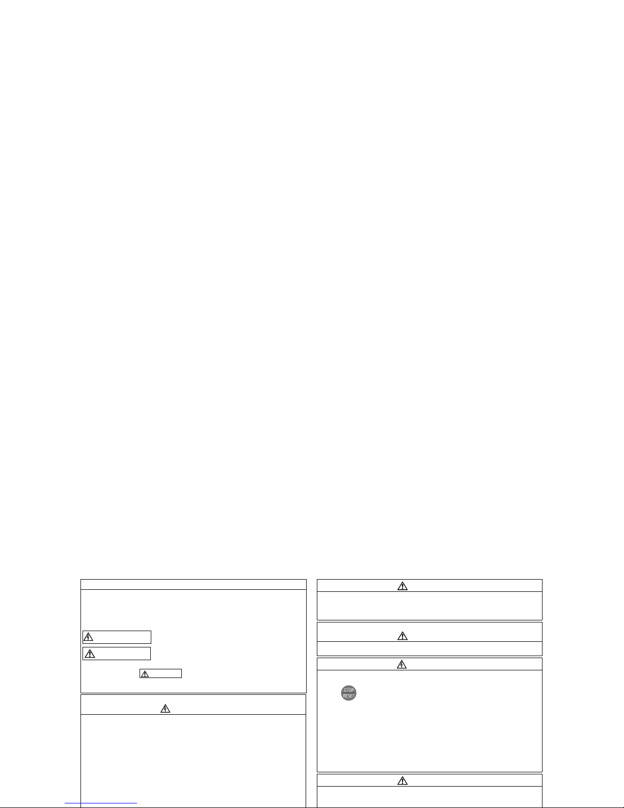
2.2 Method of removal and reinstallation of the front cover
•Removal of the operation panel
1) Loosen the two screws on the operation panel.
(These screws cannot be removed.)
2) Push the left and right hooks of the operation panel
and pull the operation panel toward you to remove.
When reinstalling the operation panel, insert it straight to reinstall securely and tighten the fixed screws of the
operation panel.
Page 10
Method of removal and reinstallation of the
front cover
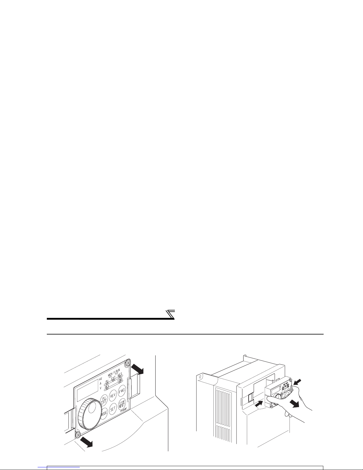
FR-F740-00770-EC or more
•
Removal
•Reinstallation
Front cover 2
Front cover 1
Installation hook
1) Remove installation screws on
the front cover 1 to remove the
front cover 1.
2) Loosen the installation
screws of the front cover 2.
3) Pull the front cover 2 toward you to
remove by pushing an installation
hook on the right side using left
fixed hooks as supports.
1) Insert the two fixed hooks on the left side of the
front cover 2 into the sockets of the inverter.
2) Using the fixed hooks as supports, securely
press the front cover 2 against the inverter.
Page 11
Installation of the inverter and instructions
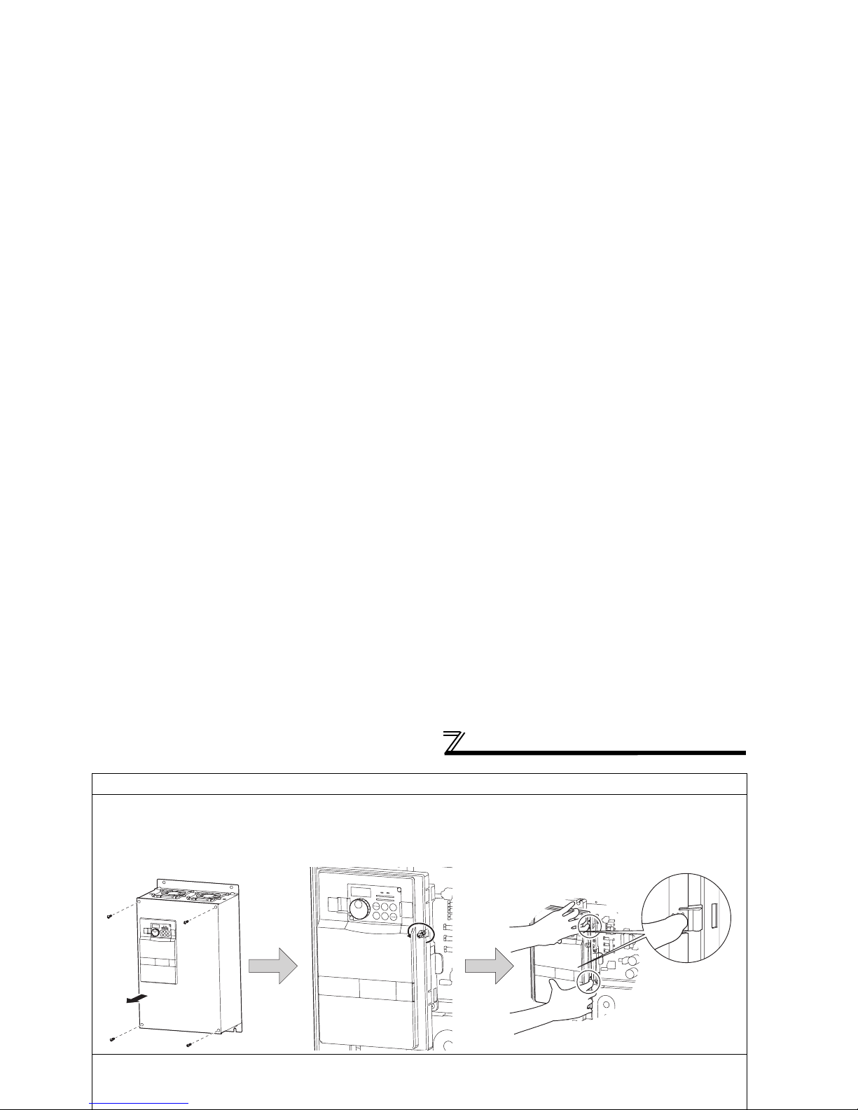
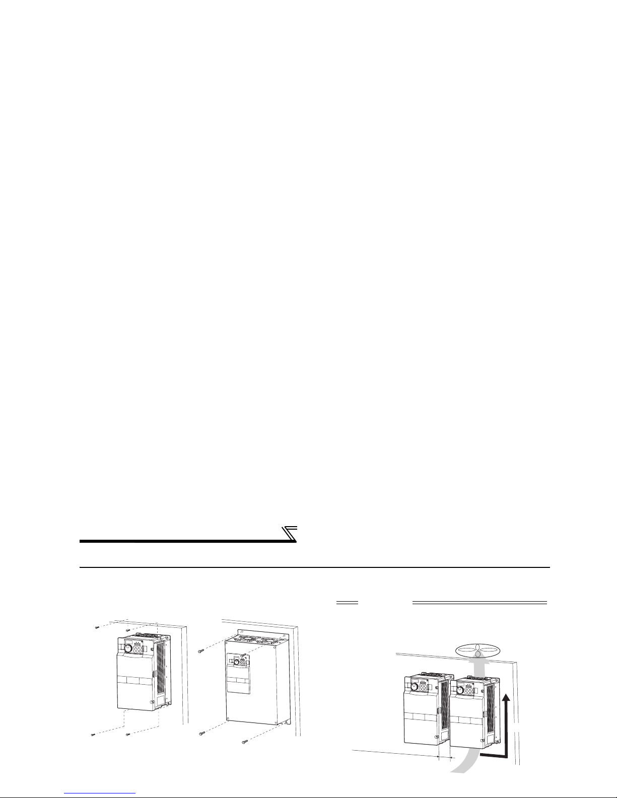
2.3 Installation of the inverter and instructions
• Installation of the Inverter
• Install the inverter under the following conditions.
Installation on the enclosure
00620 or less 00770 or more
CAUTION
⋅ When encasing multiple inverters, install them in
parallel as a cooling measure.
⋅ Install the inverter vertically.
Refer to the clearances below.
Vertical
Fix six positions for the FR-F74004320 to 08660 and fix eight positions
for the FR-F740-09620 to 12120.
Page 12
Wiring
2.4 Wiring
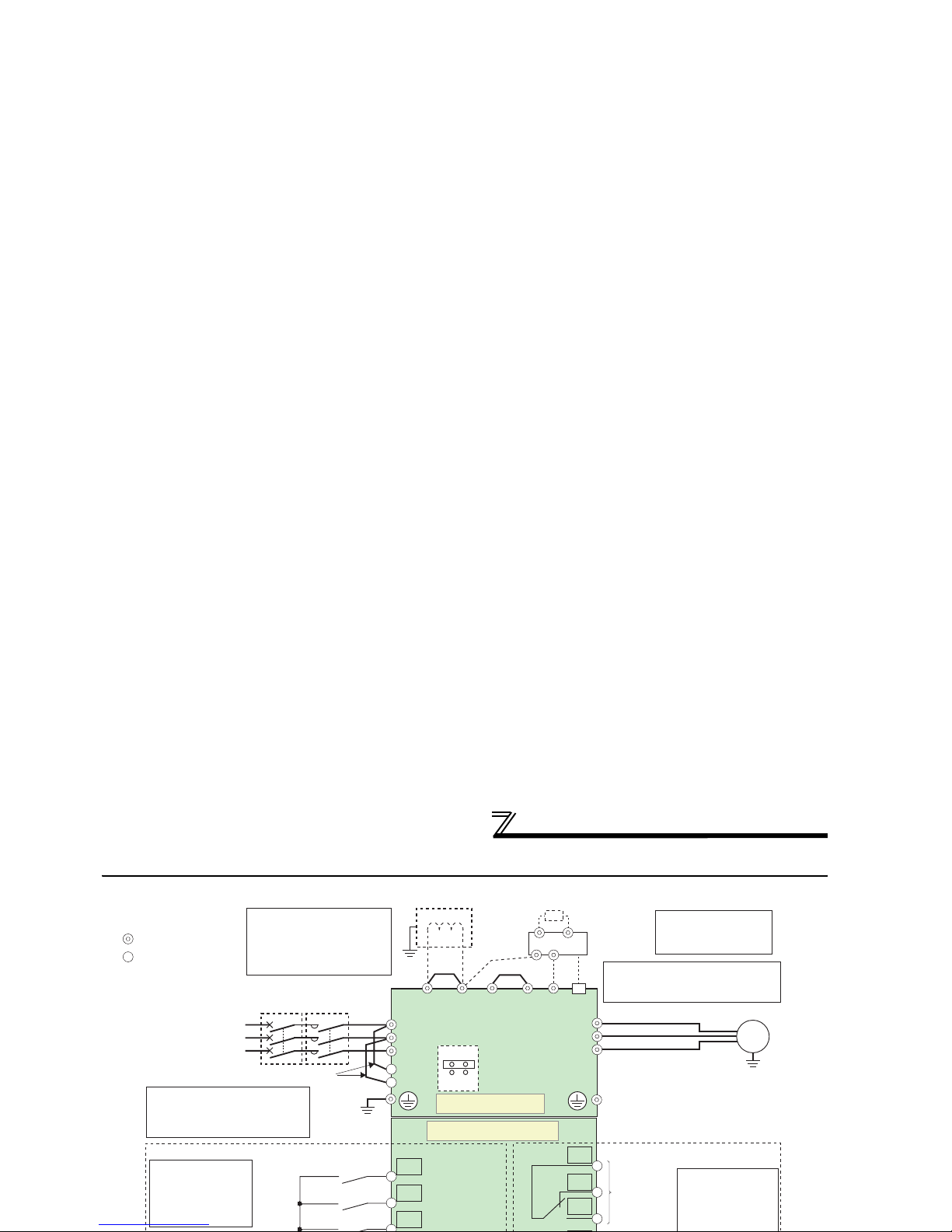
2.4.1 Terminal connection diagram
Three-phase AC
power supply
MCCB
Jumper
R/L1
S/L2
T/L3
R1/L11
S1/L21
Control input signals (No voltage input allowed)
Jumper
Motor
Relay output 1
(Alarm output)
C1
B1
A1
U
V
W
*1
Main circuit terminal
Control circuit terminal
MC
Main circuit
Control circuit
Relay output
IM
Terminal functions
vary with the output
terminal assignment
(Pr. 195, Pr. 196)
Terminal functions
vary with the input
terminal assignment
(Pr. 178 to Pr. 189)
STF
STR
STOP
EMC filter
ON/OFF
connector
ON
OFF
Forward
rotation
start
Reverse
rotation
start
PR*7
PX*7
Jumper
*7.
*2. To supply power to the
control circuit separately,
remove the jumper across
R1/L11 and S1/L21.
*2
Do not use PR and PX terminals.
Please do not remove the jumper
connected to terminal PR and PX.
N/-
P/+
P1
Resistor unit
(Option)
Brake unit
(Option)
CN8
*6
Source logic
Earth
Earth
Earth
*6. A CN8 connector is
provided with the
01800 or more.
*1. DC reactor (FR-HEL)
Be sure to connect the DC reactor
supplied with the 01800 or more.
When a DC reactor is connected
to the 01160 or less, remove the
jumper across P1-P/+.
(Refer to the Instruction
Manual (applied))
(Refer to the
Instruction Manual
Page 13

Wiring
2.4.2 EMC filter
This inverter is equipped with a built-in EMC filter (capacitive filter) and common mode core.
The EMC filter is effective for reduction of air-propagated noise on the input side of the inverter.
The EMC filter is factory-set to enable (ON). To disable it, fit the EMC filter ON/OFF connector to the OFF position.
The input side common mode core, built-in the FR-F740-01160 or less inverter, is always valid regardless of on/off of
the EMC filter on/off connector.
EMC filter OFF EMC filter OFF EMC filter OFFEMC filter ON EMC filter ON EMC filter ON
(initial setting) (initial setting) (initial setting)
EMC filte
r
ON/OFF
connecto
r
00023 to 00126
00170, 00250
00310 or more
00170, 00250
00310, 00380
00470, 00620
00770 or more
00023 to 00126
Page 14
Wiring
2.4.3 Specification of main circuit terminal
Term inal
Symbol
Term inal Name Description
R/L1,
S/L2,
T/L3
AC power input
Connect to the commercial power supply.
Keep these terminals open when using the high power factor converter
(FR-HC, MT-HC) or power regeneration common converter (FR-CV).
U, V, W Inverter output Connect a three-phase squirrel-cage motor.
R1/L11,
S1/L21
Power supply for
control circuit
Connected to the AC power supply terminals R/L1 and S/L2. To retain the
alarm display and alarm output or when using the high power factor
converter (FR-HC, MT-HC) or power regeneration common converter (FRCV), remove the jumpers from terminals R/L1-R1/L11 and S/L2-S1/L21
and apply external power to these terminals.
Do not turn off the power supply for control circuit (R1/L11, S1/L21) with the
main circuit power (R/L1, S/L2, T/L3) on. Doing so may damage the
inverter. The circuit should be configured so that the main circuit power (R/
L1, S/L2, T/L3) is also turned off when the power supply for control circuit
(R1/L11, S1/L21) is off.
00380 or less : 60VA, 00470 or more : 80VA
P/+, N/-
Brake unit
Connect the brake unit (FR-BU, BU and MT-BU5), power regeneration
common converter (FR-CV), high power factor converter (FR-HC and
Page 15
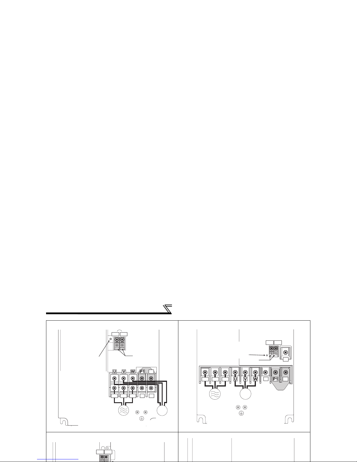
Wiring
FR-F740-00310, 00380-EC FR-F740-00470, 00620-EC
FR-F740-00770 to 01160-EC FR-F740-01800 to 02600-EC
R1/L11 S1/L21
R/L1 S/L2 T/L3
N/-
P/+
PR
Charge lamp
Jumper
Jumper
Screw size
(M4)
Screw size (M5)
Screw size (M5)
Power supply
IM
Motor
R/L1 S/L2 T/L3
N/-
P/+
PR
R1/L11 S1/L21
IM
Screw size (M4)
Screw size (M6)
Screw size (M6)
Jumper
Jumper
Charge lamp
Power supply
Motor
Screw size(M4)
R1/L11 S1/L21
Page 16

Wiring
FR-F740-03250 to 04810-EC FR-F740-05470 to 12120-EC
IM
R/L1 S/L2 T/L3
N/-
P/+
R1/L11 S1/L21
P/+
P/+
Screw size (M4)
Jumper
Charge lamp
Screw size
(M10)
Motor
Screw size (M12)
(for option)
Power supply
DC reactor
Screw size
(03250/03610: M10
04320/04810: M12)
IM
R/L1 S/L2 T/L3
N/-
R1/L11 S1/L21
P/+
P/+
Screw size (M4)
Jumper
Charge lamp
Motor
Power supply
DC reactor
Screw size (M12)
Page 17

Wiring
(1) Cable sizes etc., of the main control circuit terminals and earth terminals
Select the recommended cable size to ensure that a voltage drop will be 2% max.
If the wiring distance is long between the inverter and motor, a main circuit cable voltage drop will cause the motor
torque to decrease especially at the output of a low frequency.
The following table indicates a selection example for the wiring length of 20m.
400V class (when input power supply is 440V based on the rated current for 110% overload for 1 minute)
Applicable Inverter
Typ e
Ter min al
Screw Size
*4
Tightening
Tor que N· m
Crimping
(Compression)
Ter mina l
Cable Sizes
HIV, etc. (mm2) *1 AWG/MCM *2 PVC, etc. (mm2) *3
R/L1,
S/L2,
T/L3
U, V,
W
R/L1,
S/L2,
T/L3
U, V,
W
cable
R/L1,
S/L2,
T/L3
U, V, W
R/L1,
S/L2,
T/L3
U, V, W cable
FR-F740-00023 to
00083-EC
M4 1.5 2-4 2-4 2 2 2 14 14 2.5 2.5 2.5
FR-F740-00126-EC M4 1.5 2-4 2-4 2 2 3.5 12 14 2.5 2.5 4
FR-F740-00170-EC M4 1.5 5.5-4 5.5-4 3.5 3.5 3.5 12 12 4 4 4
FR-F740-00250-EC M4 1.5 5.5-4 5.5-4 5.5 5.5 8 10 10 6 6 10
FR-F740-00310-EC M5 2.5 8-5 8-5 88888101010
FR-F740-00380-EC M5 2.5 14-5 8-5 14 8 14 6 8 16 10 16
FR-F740-00470-EC M6 4.4 14-6 14-6 14 14 14 6 6 16 16 16
FR-F740-00620-EC M6 4.4 22-6 22-6 22 22 14 4 4 25 25 16
FR-F740-00770-EC M6 4.4 22-6 22-6 22 22 14 4 4 25 25 16
FR-F740-00930-EC M8 7.8 38-8 38-8 38 38 22 1 2 50 50 25
Page 18

Wiring
(2) Notes on earthing
• Leakage currents flow in the inverter. To prevent an electric shock, the inverter and motor must be earthed. This inverter
must be earthed. Earthing must conform to the requirements of national and local safety regulations and electrical
codes. (NEC section 250, IEC 536 class 1 and other applicable standards)
• Use the dedicated earth terminal to earth the inverter.
(Do not use the screw in the casing, chassis, etc.)
• Use the thickest possible
earth
cable. Use the cable whose size is equal to or greater than that indicated in the above
table, and minimize the cable length. The earthing point should be as near as possible to the inverter.
To be compliant with the European Directive (Low Voltage Directive), earth the inverter according to
the instructions on page 135.
(3) Total wiring length
The overall wiring length for connection of a single motor or multiple motors should be within the value in the table below.
Pr. 72 PWM frequency selection Setting
(carrier frequency) *
00023 00038
00052 or
More
2 (2kH) or less 300m 500m 500m
3 (3kHz), 4 (4kHz) 200m 300m 500m
5 (5kHz) to 9 (9kHz) 100m
10 (10kHz) or more 50m
Page 19

Wiring
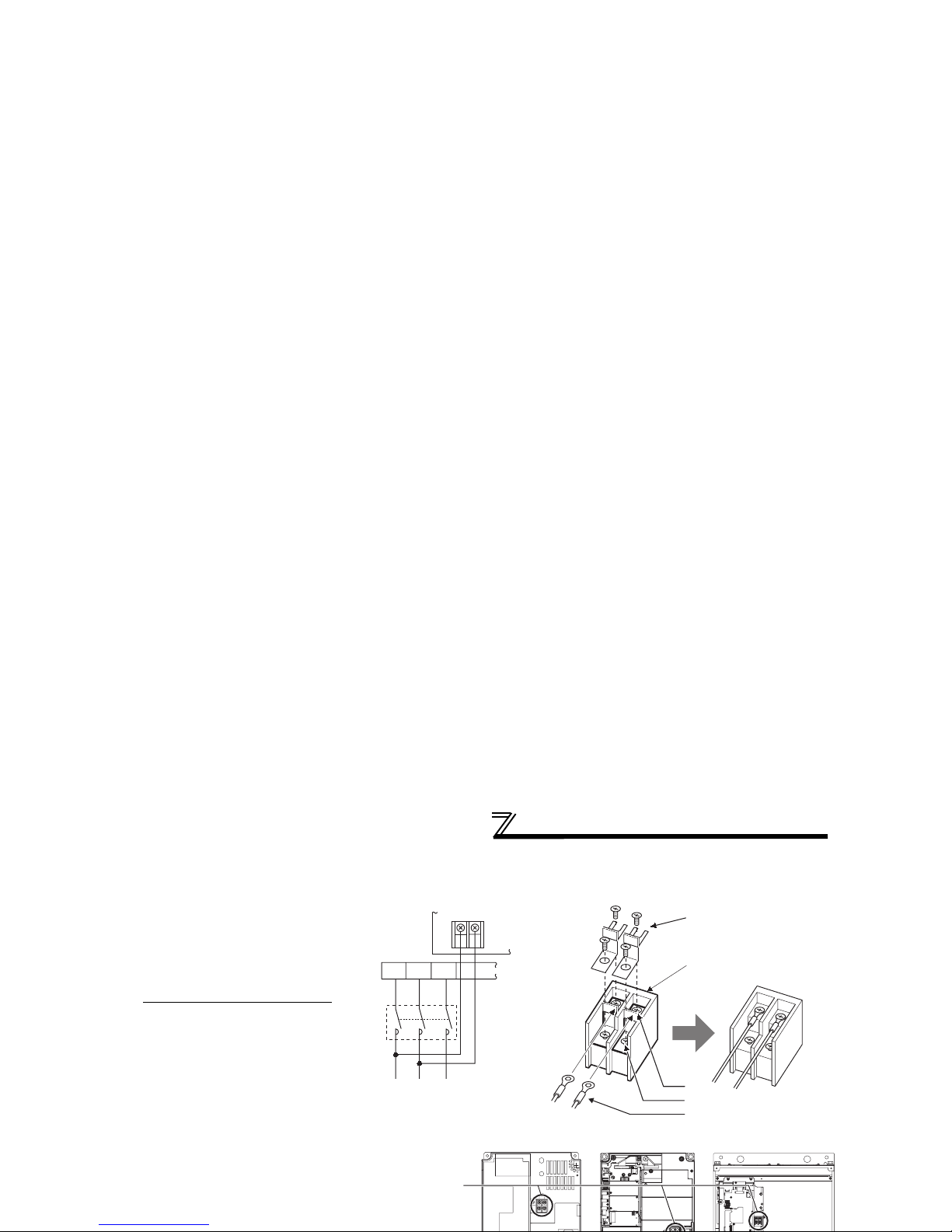
(5) When connecting the control circuit and the main circuit separately to the power supply
(separate power)
• FR-F740-00023 to 00126
<Connection diagram> When the protected circuit is activated, opening of the electromagnetic
contactor (MC) on the inverter power supply side results in power loss in the
control circuit, disabling the alarm output signal retention. Terminals R1/L11
and S1/L21 are provided to hold an alarm signal. In this case, connect the
power supply terminals R1/L11 and S1/L21 of the control circuit to the
primary side of the MC.
1)Loosen the upper screws.
2)Remove the lower screws.
3)Remove the jumper
4)Connect the separate power
supply cable for the control
circuit to the lower terminals
Inverter
MC
R/L1
S/L2
T/L3
R1/L11
S1/L21
Remove the jumper
3)
Page 20
Wiring
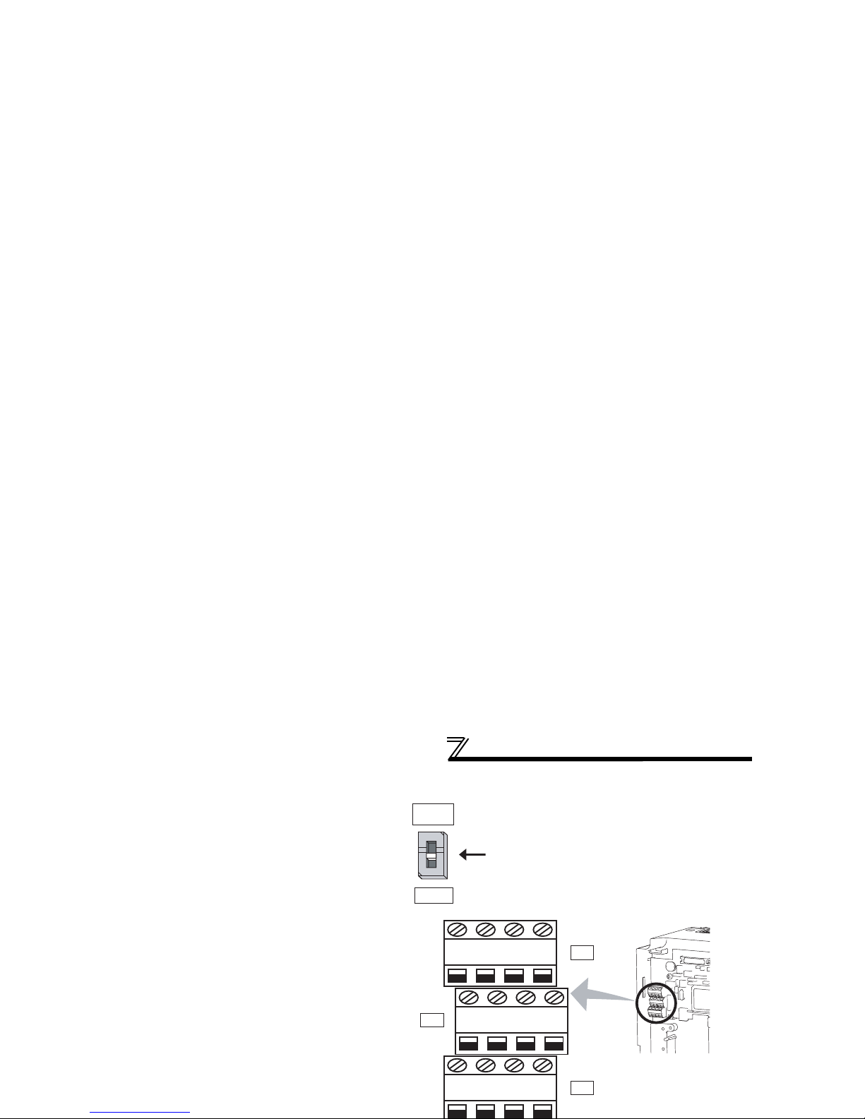
• FR-F740-00310 or more
1)Remove the upper screws.
2)Remove the lower screws.
3)Pull the jumper toward you to
remove.
4)
Connect the separate power supply
cable for the control circuit to the
upper terminals (R1/L11, S1/L21)
.
Never connect the power cable to
the terminals in the lower stand.
Doing so will damage the inverter.
S1/L21
R1/L11
3)
4)
1)
2)
Power supply
terminal block for
the control circuit
Power supply terminal block
for the control circuit
R/L1
S/L2
T/L3
R1/
L11
S1/
L21
Power supply
terminal block
for the control circuit
Main power supply
MC
00310, 00380
00470, 00620
00770 or more
Page 21

Wiring
2.4.5 Control circuit terminals
indicates that terminal functions can be selected using Pr. 178 to Pr. 196 (I/O terminal function selection) (Refer to
Instruction Manual (applied).)
(1) Input signals
Typ e
Terminal
Symbol
Ter min al
Name
Description
Rated
Specifications
Refer to
STF
Forward
rotation start
Turn on the STF signal to start forward
rotation and turn it off to stop.
When the STF and
STR signals are turned
on simultaneously, the
stop command is given.
42
STR
Reverse
rotation start
Turn on the STR signal to start reverse
rotation and turn it off to stop.
STOP
Star t selfholding
selection
Turn on the STOP signal to self-hold the start signal.
Instruction
Manual
(applied)
RH,
RM, RL
Multi-speed
selection
Multi-speed can be selected according to the combination of RH,
RM and RL signals.
44
JOG
Jog mode
selection
Turn on the JOG signal to select Jog operation (initial setting) and
turn on the start signal (STF or STR) to start Jog operation.
Instruction
Manual
(applied)
Second
Turn on the RT signal to select second function.
When the second function such as "second torque boost" and
Instruction
Page 22
Wiring
Frequency setting
10E
Frequency
setting power
supply
When connecting the frequency setting potentiometer at an initial
status, connect it to terminal 10.
Change the input specifications of terminal 2 when connecting it
to terminal 10E. (Refer to Pr. 73 Analog input selection in
Instruction Manual (applied).)
10VDC
Permissible load
current 10mA
Instruction
Manual
(applied)
10
5VDC
Permissible load
current 10mA
38, 46
2
Frequency
setting
(voltage)
Inputting 0 to 5VDC (or 0 to 10V, 0 to 20mA) provides the
maximum output frequency at 5V (10V, 20mA) and makes input
and output proportional. Use Pr. 73 to switch from among input 0
to 5VDC (initial setting), 0 to 10VDC, and 0 to 20mA.
Set the voltage/current input switch in the ON position to select
current input (0 to 20mA).
*1
Voltage input:
Input resistance
10kΩ ± 1kΩ
Maximum
permissible
voltage 20VDC
Current input:
Input resistance
245Ω ± 5Ω
Maximum
permissible
current 30mA
38, 46
4
Frequency
setting
(current)
Inputting 4 to 20mADC (or 0 to 5V, 0 to 10V) provides the
maximum output frequency at 20mA (5V, 10V) makes input and
output proportional. This input signal is valid only when the AU
signal is on (terminal 2 input is invalid). Use Pr. 267 to switch from
among input 4 to 20mA (initial setting), 0 to 5VDC, and 0 to
10VDC. Set the voltage/current input switch in the OFF position
to select voltage input (0 to 5V/0 to 10V).
*1
(Refer to Instruction Manual (applied).)
40, 48
1
Frequency
setting
Inputting 0 to ±5 VDC or 0 to ±10VDC adds this signal to terminal
2 or 4 frequency setting signal. Use Pr.73 to switch between the
Input resistance
10kΩ ± 1kΩ
Maximum
Instruction
Manual
Typ e
Terminal
Symbol
Terminal
Name
Description
Rated
Specifications
Refer to
Page 23

Wiring
*2 Low indicates that the open collector output transistor is on (conducts).
High indicates that the transistor is off (does not conduct).
*3 Not output during inverter reset.
(3) Communication
Analog
CA
Analog current
output
Select one e.g. output frequency from
monitor items.
*3
The output signal is proportional to the
magnitude of the corresponding
monitoring item.
Output item:
Output frequency
(initial setting)
Load impedance
200Ω to 450Ω
Output signal 0 to
20mADC
Instruction
Manual
(applied)
AM
Analog voltage
output
Output signal 0 to
10VDC
Permissible load
current 1mA
(load impedance
10kΩ or more)
Resolution 8 bit
Instruction
Manual
(applied).
Type
Terminal
Symbol
Terminal
Name
Description Refer to
—
PU
With the PU connector, communication can be made through RS-485.
(for connection on a 1:1 basis only)
. Conforming standard : EIA-485(RS-485)
22
Typ e
Terminal
Symbol
Terminal
Name
Description
Rated
Specifications
Refer to
Page 24

Wiring
Sink logic and source logic
⋅ In sink logic, a signal switches on when a current flows from the corresponding signal input terminal.
Terminal SD is common to the contact input signals. Terminal SE is common to the open collector output signals.
⋅ In source logic, a signal switches on when a current flows into the corresponding signal input terminal.
Terminal PC is common to the contact input signals. Terminal SE is common to the open collector output signals.
Current
PC
STF
R
STR
R
Source logic
Source
connecto
r
Current
SD
STF
R
STR
R
Sink
connector
Sink logic
Current flow concerning the input/output signal
when sink logic is selected
Current flow concerning the input/output signal
when source logic is selected
DC input (source type)
<Example: AX80>
Inverter
DC input (sink type)
<Example: AX40>
Inverter
Page 25
Wiring
2.4.7 Wiring of control circuit
(1) Control circuit terminal layout
(2) Wiring method
Loosen the terminal screw and insert the cable into the terminal.
Screw Size: M3 Tightening Torque: 0.5N·m to 0.6N·m
Cable size: 0.3mm
2
to 0.75mm
2
Screwdriver:Small flat-blade screwdriver (Edge thickness: 0.4mm/
Edge width: 2.5mm)
Wire the stripped cable after twisting it to
prevent it from becoming loose. In addition, do
not solder it.
STOP
AURHRM
RL
C2B2A2C1B1A1
OLIPFSURUNSE14521010EAMPC
FU
MRS
JOG CS
RES STF STR PC
CA SD PC
RT
CAUTION
Undertightening can cause cable disconnection or malfunction.
Overtightening can cause a short circuit or malfunction due to
Cable stripping size
6mm
Page 26
Wiring
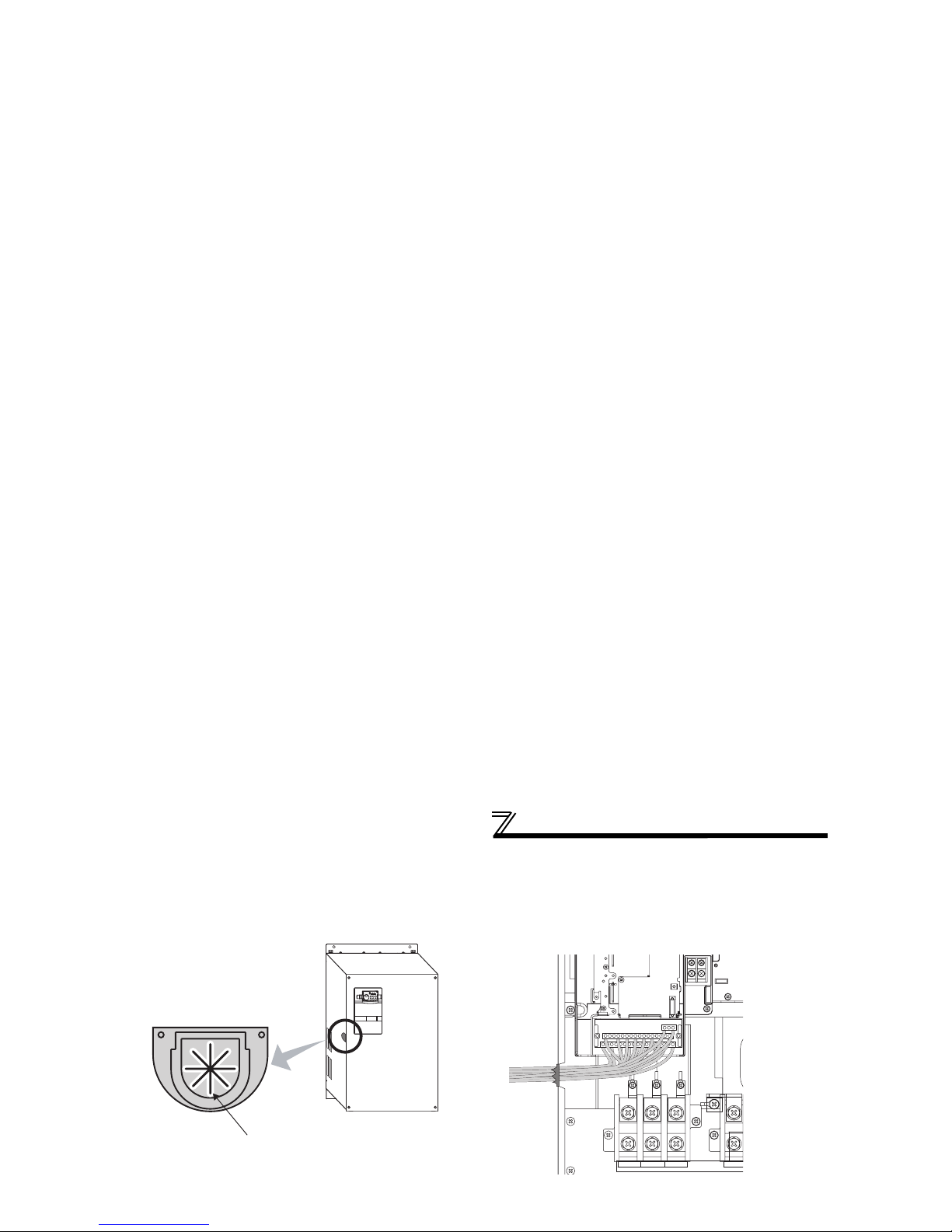
z Wiring of the control circuit of the 01800 or more
For wiring of the control circuit of the 01800 or more, separate away from wiring of the main circuit.
Make cuts in rubber bush of the inverter side and lead wires.
<Wiring>
Rubber bush
(view from the inside)
Make cuts along the lines inside with
a cutter knife and such.
Page 27
Wiring
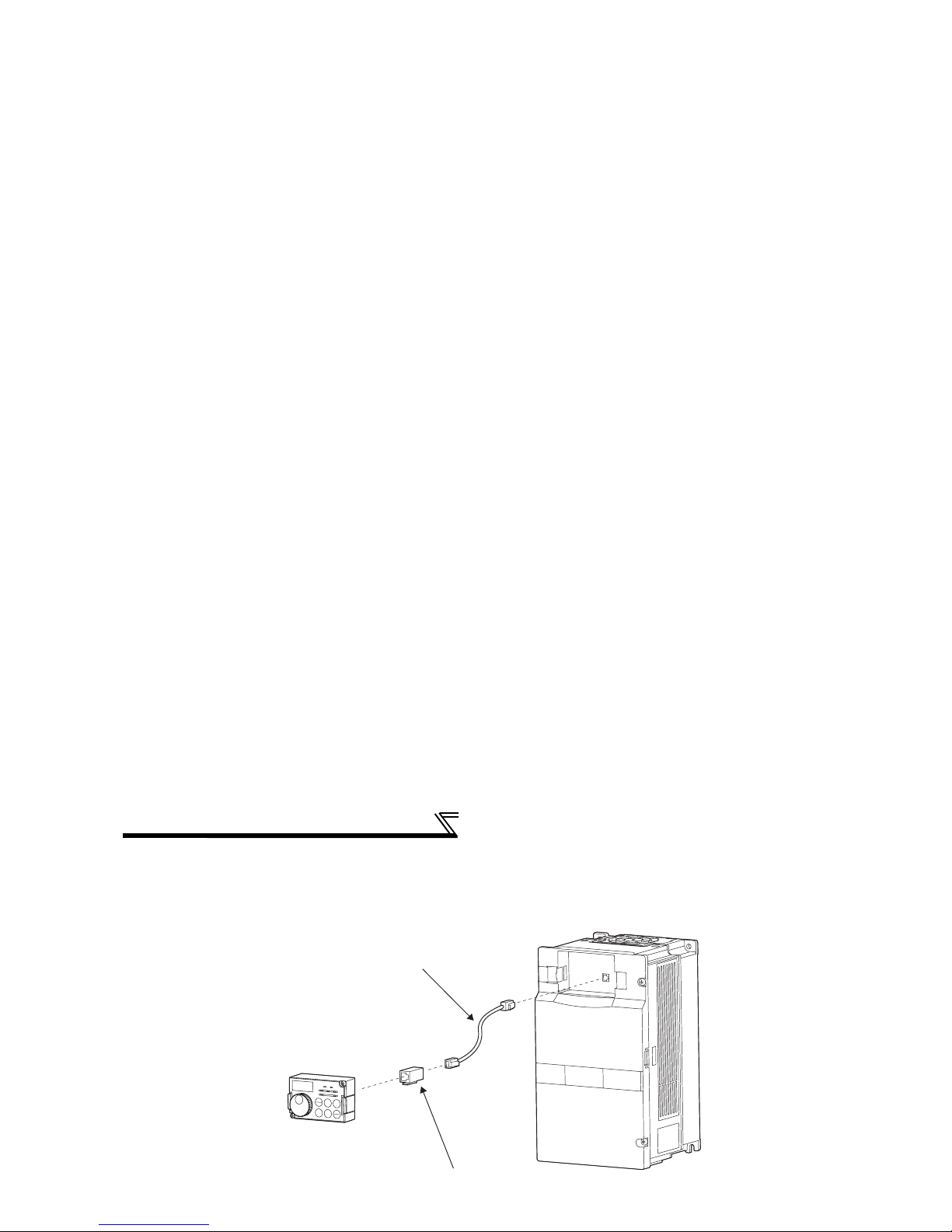
2.4.8 When connecting the operation panel using a connection cable
When connecting the operation panel (FR-DU07) to the inverter using a cable, the operation panel can be mounted
on the enclosure surface and operationality improves.
Parameter unit connection cable
(FR-CB2)(option)
Operation panel(FR-DU07)
Operation panel connection connector
(FR-ADP)(option)
Page 28
Wiring
2.4.9 RS-485 terminal block
⋅ Conforming standard: EIA-485(RS-485)
⋅ Transmission format: Multidrop link
⋅ Communication speed: MAX 38400bps
⋅ Overall length: 500m
⋅ Connection cable:Twisted pair cable
(4 paires)
RXD
RDA1
(RXD1+)
RDB1
(RXD1-)
RDA2
(RXD2+)
RDB2
(RXD2-)
SDA1
(TXD1+)
SDB1
(TXD1-)
SDA2
(TXD2+)
SDB2
(TXD2-)
P5S
(VCC)SG(GND)
P5S
(VCC)SG(GND)
VCC
TXD
OPEN
100Ω
Terminating resistor switch
Factory-set to "OPEN".
Set only the terminating resistor switch of
the remotest inverter to the "100Ω" position.
Page 29

Power-off and magnetic contactor (MC)
2.5 Power-off and magnetic contactor (MC)
(1) Inverter input side magnetic contactor (MC)
On the inverter input side, it is recommended to provide an MC for the following purposes.
(
Refer to page 3 for selection.)
1)To release the inverter from the power supply when the inverter's protective function is activated or when the drive is
not functioning (e.g. emergency stop operation).
2)
To prevent any accident due to an automatic restart at restoration of power after an inverter stop made by a power failure
3)The control power supply for inverter is always running and consumes a little power. When stopping the inverter for an
extended period of time, powering off the inverter will save power slightly.
4)To separate the inverter from the power supply to ensure safe maintenance and inspection work
The inverter's input side MC is used for the above purpose, select class JEM1038-AC3MC for the inverter input side
current when making an emergency stop during normal operation.
REMARKS
Since repeated inrush current at powering on will shorten the life of the converter part (switching life is 100 million times), frequent
on/off must be avoided. Turn on/off the inverter start controlling terminals (STF, STR) to run/stop the inverter.
• Inverter start/stop circuit example
As shown on the left, always use the start signal
(ON or OFF across terminals STF or STR-PC) to
make a start or stop.
*1 When the power supply is 400V class, install a step-
Power
supply
MCCB
U
V
W
To the
motor
MC
R/L1
S/L2
T/L3
Page 30

Precautions for use of the inverter
2.6 Precautions for use of the inverter
The FR-F700 series is a highly reliable product, but incorrect peripheral circuit making or operation/handling method
may shorten the product life or damage the product.
Before starting operation, always recheck the following items.
(1) Use crimping terminals with insulation sleeve to wire the power supply and motor.
(2) Application of power to the output terminals (U, V, W) of the inverter will damage the inverter. Never perform such wiring.
(3) After wiring, wire offcuts must not be left in the inverter.
Wire offcuts can cause an alarm, failure or malfunction. Always keep the inverter clean. When drilling mounting holes in
an enclosure etc., take care not to allow chips and other foreign matter to enter the inverter.
(4) Use cables of the size to make a voltage drop 2% maximum.
If the wiring distance is long between the inverter and motor, a main circuit cable voltage drop will cause the motor torque
to decrease especially at the output of a low frequency.
Refer to page 12 for the recommended cable sizes.
(5) The overall wiring length should be 500m maximum.
Especially for long distance wiring, the fast-response current limit function may decrease or the equipment connected to the
secondary side may malfunction or become faulty under the influence of a charging current due to the stray capacity of the
wiring. Therefore, note the overall wiring length. (Refer to page 13.)
Page 31

Precautions for use of the inverter
(13) If the machine must not be restarted when power is restored after a power failure, provide a magnetic contactor in the
inverter's input side and also make up a sequence which will not switch on the start signal.
If the start signal (start switch) remains on after a power failure, the inverter will automatically restart as soon as the
power is restored.
(14) Instructions for overload operation
When performing an operation of frequent start/stop of the inverter, increase/decrease in the temperature of the
transistor element of the inverter may repeat due to a continuous flow of large current, shortening the life from thermal
fatigue. Since thermal fatigue is related to the amount of current, the life can be increased by reducing bound current,
starting current, etc. Decreasing current may increase the life. However, decreasing current will result in insufficient
torque and the inverter may not start. Therefore, increase the inverter capacity to have enough allowance for current.
(15) Make sure that the specifications and rating match the system requirements.
Page 32

Step of operation
3 DRIVE THE MOTOR
3.1 Step of operation
The inverter needs frequency command and start command. Turning the start command on
start the motor rotating and the motor speed is determined by the frequency command (set
frequency).
Refer to the flow chart below to perform setting.
Step of operation
o
p
Step of operation
Installation/mounting
System examination
Wiring of the power
supply and motor
{Refer to page 9}
{Refer to page 6}
Page 33

Operation panel (FR-DU07)
3.2 Operation panel (FR-DU07)
3.2.1 Parts of the operation panel (FR-DU07)
PU: Lit to indicate PU operation mode.
EXT: Lit to indicate external operation mode.
NET: Lit to indicate network operation mode.
Rotation direction indication
REV: Lit during reverse rotation
FWD: Lit during forward rotation
Unit indication
· Hz: Lit to indicate frequency.
· A: Lit to indicate current.
Operation mode indication
On: Forward/reverse operation
Flickering: When the frequency command is
not given even if the
forward/reverse command is given.
Page 34

Operation panel (FR-DU07)
3.2.2 Basic operation (factory setting)
At powering on (external operation mode)
PU operation mode
(output frequency monitor)
PU Jog operation mode
Output current monitor
Output voltage monitor
Value change
(Example)
Frequency setting has been
written and completed!!
and frequency flicker.
Operation mode switchover
Monitor/frequency setting
(Refer to page 32)
Page 35

Operation panel (FR-DU07)
3.2.3 Operation lock (Press [MODE] for an extended time (2s))
· Set "10 or 11" in Pr. 161, then press for 2s to make the setting dial and key operation invalid.
· When the setting dial and key operation is made invalid, appears on the operation panel.
When the setting dial and key operation is invalid, appears if the setting dial or key operation is
performed. (When the setting dial or key operation is not performed for 2s, the monitor display appears.)
· To make the setting dial and key operation valid again, press for 2s.
Operation using the setting dial and key of the operation panel can be made invalid to prevent parameter
change and unexpected start and stop.
POINT
Set "0" (extended mode parameter valid) in Pr.160 User group read selection.
Set "10 or 11" (key lock mode valid) in Pr.161 Frequency setting/key lock operation selection.
1.Screen at powering on
Display
Operation
Page 36

Operation panel (FR-DU07)
3.2.4 Monitoring of output current and output voltage
POINT
Monitor display of output frequency, output current and output voltage can be changed by pushing during
monitoring mode.
2.Independently of whether the inverter is running
in any operation mode or at a stop, the output
current monitor appears by pressing .
3.Press to show the output voltage monitor.
1.Press during operation to choose the output
frequency monitor
Display
Operation
Page 37

Operation panel (FR-DU07)
3.2.7 Change the parameter setting value
Changing example Change the Pr. 1 Maximum frequency .
1.Screen at powering on
The monitor display appears.
Display
Operation
3.Press to choose the parameter
setting mode.
4. Pr. 1) appears.
5.Press to read the currently set value.
" "(initial value) appears.
PU indication is lit.
2.Press to choose the PU operation
mode.
The parameter
number read
previously appears.
Page 38

Overheat protection of the motor by the inverter (Pr. 9)
3.3 Overheat protection of the motor by the inverter (Pr. 9)
Set the rated motor current in Pr. 9 Electronic thermal O/L relay to protect the motor from overheat.
Parameter
Number
Name Initial Value Setting Range *2 Description
9 Electronic thermal O/L relay
Inverter rated
current
*1
01160 or less
0 to 500A
Set the rated motor current.
01800 or more
0 to 3600A
*1 Refer to page 116 for the rated inverter current value.
*2 The minimum setting increments are 0.01A for the
01160
or less and 0.1A for the
01800
or more.
Changing example
Change the Pr. 9 Electronic thermal O/L relay setting to 2.0A according to the motor rated current.
(FR-F740-00023)
1.Screen at powering on
The monitor display appears.
2.Press to choose the PU
operation mode.
PU indication is lit.
Display
Operation
Page 39

Start/stop from the operation panel (PU
operation mode)
3.4 Start/stop from the operation panel (PU operation mode)
3.4.1 Set the set frequency to operate (example: performing operation at 30Hz)
POINT
From where is the frequency command given?
· Operation at the frequency set in the frequency setting mode
of the operation panel →Refer to 3.4.1 (Refer to page 34)
· Operation using the setting dial as the volume
→Refer to 3.4.2 (Refer to page 35)
· Change of frequency with ON/OFF switches connected to
terminals →Refer to 3.4.3 (Refer to page 36)
· Frequency setting with a voltage output device
→Refer to 3.4.4 (Refer to page 38)
· Frequency setting with a current output device
→Refer to 3.4.5 (Refer to page 40)
Three-phase
A
C power supply
Motor
Inverter
R/L1
S/L2
T/L3
U
V
W
FR-DU07
,
,
[Connection diagram]
1.
Screen at powering on
The monitor display appears.
2.
Press to choose the PU
PU indication is lit.
Display
Operation
Page 40

Start/stop from the operation panel (PU
operation mode)
3.4.2 Use the setting dial like a potentiometer to perform operation.
POINT
Set "0" (extended mode parameter valid) in Pr. 160 User group read selection.
Set "1" (setting dial potentiometer mode) in Pr. 161 Frequency setting/key lock operation selection.
Operation example Change the frequency from 0Hz to 50Hz during operation
DisplayOperation
PU indication is lit.
The parameter number
previously read appears.
1. Screen at powering on
The monitor display appears.
2. Press to choose the PU operation
mode.
3. Press to choose the parameter
setting mode.
4. Turn until (Pr. 160) appears.
Page 41

Start/stop from the operation panel (PU
operation mode)
3.4.3 Use switches to give a start command and a frequency setting (multi-speed
setting)
[Connection diagram]
POINT
· Use / to give a start command.
· Pr. 79 Operation mode selection must be set to "4" (external/PU combined operation mode 2)
· The initial values of the terminals RH, RM, RL are 50Hz, 30Hz, and 10Hz. (Refer to page 44 to change frequencies
using Pr. 4, Pr. 5 and Pr. 6.)
· Operation at 7-speed can be performed by turning on two (or three) terminals simultaneously.
(Refer to Instruction Manual (applied).)
ON
ON ON ON ON
ON ON
ONONON
ON
Output frequency (Hz)
Speed 1
(High speed)
Speed 2
(Middle speed)
Speed 3
(Low speed)
Speed 4
Speed 5
Speed 6
Speed 7
Time
RH
RM
RL
Three-phase
AC power supply
Moto
r
Inverter
R/L1
S/L2
T/L3
U
V
W
High speed
Middle speed
Low speed
RH
RM
RL
FR-DU07
PC
Page 42

Start/stop from the operation panel (PU
operation mode)
50Hz for the RH, 30Hz for the RM and 10Hz for the RL are not output when they are turned on ... Why?
Check for the setting of Pr. 4, Pr. 5, and Pr. 6 once again.
Check for the setting of Pr. 1 Maximum frequency and Pr. 2 Minimum frequency once again.
(Refer to page 52.)
Check that Pr. 180 RL terminal function selection = "0", Pr. 181 RM terminal function selection = "1", Pr.
182 RH terminal function selection ="2", and Pr. 59 Remote function selection = "0". (all are initial values)
[FWD (or REV)] lamp is not lit ... Why?
Check that wiring is correct. Check the wiring once again.
Flickering
9. Turn on the low speed switch (RL).
The output frequency increases to " "
(10Hz) according to Pr. 7 Acceleration time.
10. Turn off the low speed switch (RL).
The output frequency decreases to " "
(0Hz) according to Pr. 8 Deceleration time.
11. Turn off the start switch .
FWD (or REV) turns off.
Low speed
Low speed
Operation Display
Page 43

Start/stop from the operation panel (PU
operation mode)
3.4.4 Perform frequency setting by analog (voltage input)
[Connection diagram]
(The inverter supplies 5V of power to the frequency setting potentiometer.(Terminal 10)
)
POINT
· Use / to give a start command.
· Pr. 79 Operation mode selection must be set to "4" (external/PU combined operation mode 2)
Three-phase
AC power supply
Moto
r
Frequency setting
potentiometer
Inverter
R/L1
S/L2
T/L3
U
V
W
5
10
2
FR-DU07
,
DisplayOperation
Page 44

Start/stop from the operation panel (PU
operation mode)
Change the frequency (50Hz) of the maximum value of potentiometer (at 5V)
Adjust the frequency in Pr. 125 Terminal 2 frequency setting gain frequency. (Refer to page 47.)
Change the frequency (0Hz) of the minimum value of potentiometer (at 0V)
Adjust the frequency in calibration parameter C2 Terminal 2 frequency setting bias frequency. (Refer to
Instruction Manual (applied).)
Stop
Flickering
DisplayOperation
10.
Deceleration
Turn the volume (frequency setting potentiometer)
counterclockwise slowly to full.
The frequency value on the indication decreases
according to Pr. 8 Deceleration time unitl
" "
(
0.00Hz) is displayed and operation status indication
of FWD or REV flickers.
The motor stops.
11. Stop
Press .
Operation status indication of FWD (or REV)
turns off.
Page 45

Start/stop from the operation panel (PU
operation mode)
3.4.5 Perform frequency setting by analog (current input)
[Connection diagram]
POINT
· Use / to give a start command.
· Turn the AU signal on.
· Pr. 79 Operation mode selection must be set to "4" (external/PU combined operation mode 2)
Three-phase
AC power supply
Moto
r
5(-)
4(+)
AU
Inverter
R/L1
S/L2
T/L3
U
V
W
A
U signal
FR-DU07
,
Output of the
adjustment meter
(4 to 20mADC)
PC
Page 46

Start/stop from the operation panel (PU
operation mode)
REMARKS
Stop
Flickering
DisplayOperation
10.
Deceleration
Perform 4mA input.
The frequency value on the indication
decreases according to Pr. 8 Deceleration time
until
" " (
0.00Hz) is displayed and the
operation status indication of FWD or REV
flickers.
The motor stops.
11.
Stop
Press .
FWD or REV of the operation status indication
turns off.
Output of the
adjustment meter
(4 to 20mADC)
Output of the
adjustment meter
(4 to 20mADC)
9.
Acceleration → constant speed
Perform 20mA input.
The frequency value on the indication increases
according to Pr. 7 Acceleration time
until
" " (
50.00Hz) is displayed.
Page 47

Make a start and stop with terminals
(external operation)
3.5 Make a start and stop with terminals (external operation)
3.5.1 Use the set frequency set by the operation panel (Pr. 79 = 3)
POINT
From where is the frequency command given?
· Operation at the frequency set in the frequency setting mode of the operation panel → Refer to 3.5.1(Refer to page 42)
· Give a frequency command by switch (multi-speed setting) → Refer to 3.5.2 (Refer to page 44)
· Perform frequency setting by a voltage output device → Refer to 3.5.3 (Refer to page 46)
· Perform frequency setting by a current output device → Refer to 3.5.5 (Refer to page 48)
POINT
[Connection diagram]
· Switch terminal STF(STR)-PC on to give a start
command.
·Set "3" in Pr. 79 (External/PU combined
operation mode 1).
· Refer to page 34 for the set frequency by the
operation panel.
Three-phase
AC power supply
Moto
r
Inverter
R/L1
S/L2
T/L3
U
V
W
FR-DU07
STR
Forward rotation
start
Reverse rotation
start
STF
PC
Page 48

Make a start and stop with terminals
(external operation)
REMARKS
· Pr. 178 STF terminal function selection must be set to "60" (or Pr. 179 STR terminal function selection must be set to "61").
(all are initial values)
· When Pr. 79 Operation mode selection is set to "3", multi-speed operation (refer to page 44) is also made valid.
When the inverter is stopped by of the operation panel (FR-DU07), and are
Display
Operation
Stop
10.Turn the start switch (STF or STR) off.
The motor decelerates according to
Pr. 8 Deceleration time to stop.
OFF
Flicker ··· Frequency setting complete!!
9.While the value is flickering,
press to set the frequency.
If you do not press ,the value flickers
for about 5s and the display then returns
to 0.00 (display) Hz. At this time, return to
"Step 3" and set the frequency again.
Forward
rotation
Reverse
rotation
Page 49

Make a start and stop with terminals
(external operation)
3.5.2 Use switches to give a start command and a frequency setting
(multi-speed setting) (Pr. 4 to Pr. 6)
[Connection diagram]
POINT
· Start command by terminal STF (STR)-PC
· Frequency command by terminal RH, RM, RL and STR-PC
· [EXT] must be lit. (When [PU] is lit, switch it to [EXT] with .)
· The initial values of the terminals RH, RM, RL are 50Hz, 30Hz, and 10Hz. (Use Pr. 4, Pr. 5 and Pr. 6 to change.)
· Operation at 7-speed can be performed by turning two (or three) terminals simultaneously. (Refer to
Instruction Manual (applied).)
Three-phase
AC power supply
Moto
r
Inverter
R/L1
S/L2
T/L3
U
V
W
Forward
rotation start
Reverse
rotation start
STF
STR
Output frequency (Hz)
Speed 1
(High speed)
Speed 2
(Middle speed)
Speed 3
(Low speed)
Speed 4
Speed 5
Speed 6
Speed 7
Page 50

Make a start and stop with terminals
(external operation)
ON
ON
Stop
OFF
Forward rotation
Reverse rotation
High speed
Middle speed
Low speed
DisplayOperation
8.
Turn on the high speed switch (RH).
10.
Stop
Turn the start switch (STF or STR) off.
The motor stops according to Pr. 8
Deceleration time.
• 30Hz appears when RM is on and 10Hz
appears when RL is on.
Forward
rotation
Reverse
rotation
7.
Mode/monitor check
Press twice to choose the
monitor/frequency monitor.
9.
Turn the start switch (STF or STR) on.
" " (40Hz) appears.
Page 51

Make a start and stop with terminals
(external operation)
3.5.3 Perform frequency setting by analog (voltage input)
[Connection diagram]
(The inverter supplies 5V of power to frequency setting potentiometer. (Terminal 10))
Three-phase
AC power supply
Moto
r
Frequency setting
potentiometer
Inverter
R/L1
S/L2
T/L3
U
V
W
5
10
2
Forward rotation
start
Reverse rotation
start
STF
STR
PC
1.Power on → operation mode check
For the initial setting, the inverter operates
in the external operation mode [EXT] when
powering on. Check that the operation
ON
DisplayOperation
Page 52

Make a start and stop with terminals
(external operation)
3.5.4 Change the frequency (50Hz) of the maximum value of potentiometer (at 5V)
<How to change the maximum frequency?>
The motor will not rotate ... Why?
Check that [EXT] is lit.
[EXT] is valid when Pr. 79 = "0" (initial value).
Use to lit [EXT].
Check that wiring is correct. Check once again.
Change the frequency (0Hz) of the minimum value of potentiometer (at 0V)
Adjust the frequency in calibration parameter C2 Terminal 2 frequency setting bias frequency. (Refer to
Instruction Manual (applied).)
When you want to compensate frequency setting, use terminal 1.
For details, refer to Instruction Manual (applied).
Changing example When you want to use the 0 to 5VDC input frequency setting potentiometer to change the 5V-
time frequency from 50Hz (initial value) to 40Hz
Adjust to output 40Hz at 5V voltage input.
Set "40Hz" in Pr. 125.
Displ
ay
O
peration
Page 53

Make a start and stop with terminals
(external operation)
3.5.5 Perform frequency setting by analog (current input)
[Connection diagram]
POINT
· Switch terminal STF(STR)-PC on to give a start command.
· Turn the AU signal on.
· Set "2" (external operation mode) in Pr. 79 Operation mode selection
5(-)
4(+)
Three-phase
AC power supply
AU
Moto
r
Inverter
R/L1
S/L2
T/L3
U
V
W
AU signal
STF
Forward rotation start
Reverse rotation start
STR
Output of the
adjustment meter
(4 to 20mADC)
PC
Page 54

Make a start and stop with terminals
(external operation)
3.5.6 Change the frequency (50Hz) of the maximum value of potentiometer (at 20mA)
<How to change the maximum frequency?>
The motor will not rotate ... Why?
Check that [EXT] is lit.
[EXT] is valid when Pr. 79 = "0" (initial value).
Use to lit [EXT].
Check that the AU signal is on.
Turn the AU signal on.
Check that wiring is orrect. Check it again.
Change the frequency (0Hz) of the minimum value of potentiometer (at 4mA)
Adjust the frequency in calibration parameter C5 Terminal 4 frequency setting bias frequency.
(Refer to Instruction Manual (applied).)
Changing example When you want to use the 4 to 20mA input frequency setting potentiometer to change the 20mA-
time frequency from 50Hz (initial value) to 40Hz
Adjust to output 40Hz at 20mA current input.
Set "40Hz" in Pr. 126.
PU
EXT
DisplayOperation
Page 55

Simple mode parameter list
4ADJUSTMENT
4.1 Simple mode parameter list
For simple variable-speed operation of the inverter, the initial setting of the parameters may be used as they are. Set the
necessary parameters to meet the load and operational specifications. Parameter setting, change and check can be made from
the operation panel (FR-DU07). For details of parameters, refer to Instruction Manual (applied).
POINT
Only simple mode parameters are displayed by the initial setting of Pr. 160 User group read selection. Set Pr. 160 User
group read selection as required. (Refer to page 63.)
Pr. 160 Description
9999
(Initial Value)
Only the simple mode parameters can be displayed.
0 Simple mode and extended mode parameters can be displayed.
1 Only the parameters registered in the user group can be displayed.
Page 56

Increase the starting torque (Pr. 0)
4.2 Increase the starting torque (Pr. 0)
Set this parameter when "the motor with a load will not rotate", "an alarm [OL] is output, resulting in an inverter
trip due to [OC1], etc.
Parameter
Number
Name Initial Value
Setting
Range
Description
0 Torque boost
00023
6%
0 to 30%
Motor torque in the lowfrequency range can be
adjusted to the load to increase
the starting motor torque.
00038 to 00083
4%
00126, 00170
3%
00250 to 00770
2%
00930, 01160
1.5%
01800 or more
1%
Changing example
When the motor with a load will not rotate,
increase the Pr. 0 value 1% by 1% unit by
looking at the motor movement. (The guideline
is for about 10% change at the greatest.)
Output
voltage
P
r. 0
P
r.46
Setting
range
Base
frequency
0
100%
Output
frequency
Page 57

Limit the maximum and minimum
output frequency (Pr. 1, Pr. 2)
4.3 Limit the maximum and minimum output frequency (Pr. 1, Pr. 2)
Parameter
Number
Name Initial Value
Setting
Range
Description
1 Maximum frequency
01160 or less
120Hz
0 to 120Hz
Set the upper limit of the output
frequency.
01800 or more
60Hz
2 Minimum frequency
0Hz 0 to 120Hz
Set the lower limit of the output
frequency.
Changing example
Limit the frequency set by the potentiometer,
etc. to 50Hz maximum.
(Set "50"Hz in Pr. 1 Maximum frequency.)
Output frequency
(Hz)
Pr.1
Pr.18
Pr.2
Frequency setting
Clamped at the
maximum frequenc
y
Clamped at the
minimum frequency
5, 10V
(20mA)
0
(4mA)
Display
Operation
Page 58

When the rated motor frequency is 60Hz
(Pr. 3)
4.4 When the rated motor frequency is 60Hz (Pr. 3)
First, check the motor rating plate. If a frequency given on the rating plate is "60Hz" only, always set Pr. 3 Base frequency
to "60Hz".
Parameter
Number
Name Initial Value Setting Range Description
3 Base frequency
50Hz 0 to 400Hz
Set the frequency when the motor
rated torque is generated.
Changing example Change Pr. 3 Base frequency to 60Hz according to the motor rated frequency.
3.Press to choose the parameter
setting mode.
1.Screen at powering on
The monitor display appears.
2.Press to choose the PU operation
mode.
PU indication is lit.
Display
Operation
The parameter
number
read previously
Page 59

Change acceleration and deceleration time
(Pr. 7, Pr. 8)
4.5 Change acceleration and deceleration time (Pr. 7, Pr. 8)
* Depends on the Pr. 21 Acceleration/deceleration time increments setting. Τηε ινιτιαλ ϖαλυε φορ τηε σεττινγ ρανγε ισ ∀0 το 3600σ∀
ανδ σεττινγ ινχρεµεντσ ισ ∀0.1σ∀.
Set in Pr. 7 Acceleration time a larger value for a slower speed increase and a smaller value for a faster speed increase.
Set in Pr. 8 Deceleration time a larger value for a slower speed decrease and a smaller value for a faster speed decrease.
Parameter
Number
Name Initial Value
Setting
Range
Description
7 Acceleration time
00170 or less
5s
0 to 3600/
360s
*
Set the motor acceleration time.
00250 or more
15s
8 Deceleration time
00170 or less
10s
0 to 3600/
360s
*
Set the motor deceleration time.
00250 or more
30s
Changing example Change the Pr. 7 Acceleration time setting from "5s"
to "10s".
Running
frequenc
y
Acceleration
time
Deceleration
time
Time
Pr.20
Pr.7
Pr.8
Output
frequency
(Hz)
(50Hz)
Page 60

Energy saving operation (Pr. 60)
4.6 Energy saving operation (Pr. 60)
4.6.1 Energy saving operation mode (setting "4")
· When "4" is set in Pr. 60, the inverter operates in the energy saving operation mode.
· In the energy saving operation mode, the inverter automatically controls the output voltage to minimize the
inverter output voltage during a constant operation.
Without a fine parameter setting, the inverter automatically performs energy saving operation.
This inverter is appropriate for fan and pump applications
Parameter
Number
Name
Initial
Value
Setting
Range
Remarks
60 Energy saving control selection
0
0 Normal operation mode
4 Energy saving operation mode
9 Optimum excitation control mode
REMARKS
· For applications a large load torque is applied to or machines repeat frequent acceleration/deceleration, an energy saving
effect is not expected.
Page 61

Energy saving operation (Pr. 60)
1.Screen at powering on
The monitor display appears.
Display
Operation
3.Press to choose the parameter
setting mode.
4.
Turn until (
Pr. 60)
appears
.
5.Press to read the currently set value.
" "(initial value) appears.
6.
Turn to change it to the set
value " ".
PU indication is lit.
2.Press to choose the PU operation
mode.
The parameter
number previously
read appears.
Page 62

Selection of the operation command and
frequency command locations (Pr. 79)
4.7 Selection of the operation command and frequency
command locations (Pr. 79)
Select the start command location and frequency command location.
Parameter
Number
Name
Initial
Value
Setting
Range
Description
LED Indication
: Off
: On
0
Use external/PU switchover mode (press to switch
between the PU and external operation mode. (Refer to
page 34))
At power on, the inverter is in the external operation
mode.
External operation mode
PU operation mode
1 Fixed to PU operation mode
2
Fixed to external operation mode
Operation can be performed by switching between the
external and NET operation mode.
External operation mode
NET operation mode
Page 63

Parameter clear, all parameter clear
4.8 Parameter clear, all parameter clear
POINT
· Set "1" in Pr. CL parameter clear, ALLC All parameter clear to initialize parameters. (Parameters are not cleared
when "1" is set in Pr. 77 Parameter write selection. )
· Refer to the parameter list on page 64 for parameters to be cleared with this operation.
1.
Screen at powering on
The monitor display appears.
Display
Operation
3.
Press to choose the parameter
setting mode.
PU indication is lit.
2.
Press to choose the PU operation
mode.
4.
Turn until " ", " "
The parameter
number read
previously appears.
Page 64

Parameter copy and parameter verification
4.9 Parameter copy and parameter verification
4.9.1
Parameter copy
PCPY Setting Description
0 Cancel
1 Copy the source parameters to the operation panel.
2 Write the parameters copied to the operation panel into the destination inverter.
3 Verify parameters in the inverter and operation panel. (Refer to page 60.)
Multiple inverters and parameter settings can be copied.
REMARKS
· When the copy destination inverter is not the FR-F700 series or parameter copy write is performed after parameter read is stopped,
“model error ( )” is displayed.
· Refer to the parameter list on
page 64 and later for availability of parameter copy.
· When the power is turned off or an operation panel is disconnected, etc. during parameter copy write, perform write again or check the
values by parameter verification.
Display
Operation
Page 65

Parameter copy and parameter verification
4.9.2 Parameter verification
appears...Why? Parameter read error. Perform operation from step 3 again.
appears...Why? Parameter write error. Perform operation from step 8 again.
and flicker alternately
Appears when parameters are copied between the inverter of 01160 or less and 01800 or more.
1. Set "0" in Pr. 160 User group read selection.
2. Set the following setting (initial value) in Pr. 989 Parameter copy alarm release.
3. Reset Pr. 9, Pr. 30, Pr. 51, Pr. 52, Pr. 54, Pr. 56, Pr. 57, Pr. 70, Pr. 72, Pr. 80, Pr. 90, Pr. 158, Pr. 190 to Pr. 196, Pr. 893.
Whether same parameter values are set in other inverters or not can be checked.
01160 or less 01800 or more
Pr. 989 Setting 10 100
Display
Operation
1.Replace the operation panel on the
inverter to be verified.
Page 66

Parameter list
4.10Parameter list
4.10.1 List of parameters classified by purpose of use
Set the parameters according to the operating conditions. The following list indicates purpose of use and
corresponding parameters.
Purpose of Use Parameter Number
Adjust the output torque of
the motor (current)
Manual torque boost Pr. 0, Pr. 46
Simple magnetic flux vector control Pr. 80, Pr. 90
Slip compensation Pr. 245 to Pr. 247
Stall prevention operation
Pr. 22, Pr. 23, Pr. 48, Pr. 49, Pr. 66, Pr.
148, Pr. 149, Pr. 154, Pr. 156, Pr. 157
Multiple rating setting Pr. 570
Limit the output frequency
Maximum/minimum frequency Pr. 1, Pr. 2, Pr. 18
Avoid mechanical resonance points (frequency jump) Pr. 31 to Pr. 36
Set V/F pattern
Base frequency, voltage Pr. 3, Pr. 19, Pr. 47
V/F pattern matching applications Pr. 14
Adjustable 5 points V/F Pr. 71, Pr. 100 to Pr. 109
Pr. 4 to Pr. 6, Pr. 24 to Pr. 27,
Page 67

Parameter list
Operation selection at power
failure and instantaneous
power failure
Restart operation after instantaneous power failure/Flying
start
Pr. 57, Pr. 58, Pr. 162 to Pr. 165, Pr.
299, Pr. 611
Decelerate the motor to a stop at instantaneous power failure Pr. 261 to Pr. 266
Operation setting at alarm
occurrence
Retry function at alarm occurrence Pr. 65, Pr. 67 to Pr. 69
Output function of alarm code Pr. 76
Input/output phase failure protection selection Pr. 251, Pr. 872
Regeneration avoidance function Pr. 882 to Pr. 886
Energy saving operation
Energy saving control selection Pr. 60
How much energy can be saved (energy saving monitor) Pr. 891 to Pr. 899
Reduction of the motor noise
Measures against noise and
leakage currents
Carrier frequency and SoftPWM selection Pr. 72, Pr. 240, Pr. 260
Noise elimination at the analog input Pr. 74
Frequency setting by analog
input
Analog input selection Pr. 73, Pr. 267, Pr. 573
Override function Pr. 73, Pr. 252, Pr. 253
Noise elimination at the analog input Pr. 74
Change of analog input frequency,
adjustment of voltage, current input and frequency
(calibration)
Pr. 125, Pr. 126, Pr. 241,
C2 to C7 (Pr. 902 to Pr. 905)
Purpose of Use Parameter Number
Page 68

Extended parameters
4.11Extended parameters
4.11.1 Used to display the extended parameters
1. Screen at powering on
The monitor display appears.
DisplayOperation
3. Press to choose the parameter
setting mode.
4. Tu
Pr. 160)
appears.
PU indication is lit.
2. Press to choose
the PU operation mode.
The parameter
number read
previously appears.
5. Press to read the currently set value.
" " (initial value) appears.
Page 69

Parameter list
4.12Parameter list
indicates simple mode parameters.
Func
t
ion
Parameter
Name
Incre
ments
Initial
Val ue
Range Description
Param
eter
copy
Param
eter
clear
All
param
eter
clear
Related
parameters
{: enabled
× : disabled
Manual torque boost
0
Torque boost
0.1%
6/4/3/2/
1.5/1%
*1
0 to 30%
Set the output voltage at 0Hz as %.
*1 Initial values differ according to the
inverter capacity.
{{{
46
Second torque
0.1% 9999
0 to 30%
Set the torque boost when the RT signal
is on.
{{{
Inverter capacity
Initial value
400V class
00023 6%
00038 to 00083 4%
00126, 00170 3%
00250 to 00770 2%
00930, 01160 1.5%
01800 or more 1%
Page 70

Parameter list
Parameter list
Acceleration/deceleration time setting
7
Acceleration time
0.1/
0.01s
5/15s
*4
0 to 3600/
360s
Set the motor acceleration time.
*4 Initial values differ according to the inverter
capacity. (
00170
or less/
00250
or more)
{{{
8
Deceleration time
0.1/
0.01s
10/30s
*5
0 to 3600/
360s
Set the motor deceleration time.
*5 Initial values differ according to the inverter
capacity. (
00170
or less/
00250
or more)
{{{
20
Acceleration/
deceleration
reference frequency
0.01Hz 50Hz 1 to 400Hz
Set the frequency referenced as
acceleration/deceleration time. Set the
frequency change time from stop to Pr. 20
for acceleration/deceleration time.
{{{
21
Acceleration/
deceleration time
increments
10
0
Increments: 0.1s
Range: 0 to 3600s
Increments and
setting range of
acceleration/
deceleration time
setting can be
changed.
{{{
1
Increments: 0.01s
Range: 0 to 360s
44
Second
acceleration/
deceleration time
0.1/
0.01s
5s
0 to 3600/
360s
Set the acceleration/deceleration time
when the RT signal is on.
{{{
Func
t
ion
Parameter
Name
Incre
ments
Initial
Val ue
Range Description
Param
eter
copy
Param
eter
clear
All
param
eter
clear
Related
parameters
{: enabled
× : disabled
Page 71

Parameter list
Jog operation
15
Jog frequency
0.01Hz 5Hz 0 to 400Hz Set the frequency for jog operation.
{{{
16
Jog acceleration/
deceleration time
0.1/
0.01s
0.5s
0 to 3600/
360s
Set the acceleration/deceleration time for
jog operation. Set the time taken to reach
the frequency set in Pr.20 Acceleration/
deceleration reference frequency for
acceleration/deceleration time. (Initial
value is 60Hz)
In addition, acceleration/deceleration time
can not be set separately.
{{{
Logic selection
of output stop
signal (MRS)
17
MRS input selection
10
0 Open input always
{{{
2
Normally closed input (NC contact input
specifications)
—
18
Refer to Pr.1 and Pr.2.
19
Refer to Pr.3.
20,21
Refer to Pr.7 and Pr.8.
Func
t
ion
Parameter
Name
Incre
ments
Initial
Val ue
Range Description
Param
eter
copy
Param
eter
clear
All
param
eter
clear
Related
parameters
{: enabled
× : disabled
Page 72

Parameter list
Parameter list
Input compensation
of multi-speed and
remote setting
28
Multi-speed input
compensation
selection
10
0 Without compensation
{{{
1 With compensation
Acceleration/
deceleration
29
Acceleration/
deceleration pattern
selection
10
0 Linear acceleration/ deceleration
{{{
1 S-pattern acceleration/deceleration A
2 S-pattern acceleration/deceleration B
3 Backlash measures
140
Backlash
acceleration
stopping frequency
0.01Hz 1Hz 0 to 400Hz
Set the stopping frequency and time for
backlash measures.
Valid when Pr.29="3"
{{{
141
Backlash
acceleration
stopping time
0.1s 0.5s 0 to 360s
{{{
Backlash
Func
t
ion
Parameter
Name
Incre
ments
Initial
Val ue
Range Description
Param
eter
copy
Param
eter
clear
All
param
eter
clear
Related
parameters
{: enabled
× : disabled
Page 73

Parameter list
Detection of output frequency
(SU, FU, FU2 signal)
41
Up-to-frequency
sensitivity
0.1% 10% 0 to 100% Set the level where the SU signal turns on.
{{{
42
Output frequency
detection
0.01Hz 6Hz 0 to 400Hz
Set the frequency where the FU signal
turns on.
{{{
43
Output frequency
detection for
reverse rotation
0.01Hz 9999
0 to 400Hz
Set the frequency where the FU signal
turns on in reverse rotation.
{{{
9999 Same as Pr.42 setting
50
Second output
frequency detection
0.01Hz 30Hz 0 to 400Hz
Set the frequency where the FU2 signal turns
on.
{{{
—
44, 45
Refer to Pr. 7 and Pr. 8.
46
Refer to Pr. 0.
47
Refer to Pr. 3.
48, 49
Refer to Pr. 22 and Pr. 23.
—
50
Refer to Pr. 41 to Pr. 43.
51
Refer to Pr. 9.
0, 5, 6, 8 to
Select the monitor to be displayed on the
Func
t
ion
Parameter
Name
Incre
ments
Initial
Val ue
Range Description
Param
eter
copy
Param
eter
clear
All
param
eter
clear
Related
parameters
{: enabled
× : disabled
Page 74

Parameter list
Parameter list
57
Restart coasting
time
0.1s 9999
0
The coasting time is as follows:
00038 or less ................................ 0.5s,
00052 to 00170 ............................. 1.0s,
00250 to 01160 ............................. 3.0s,
01800 or more .............................. 5.0s
{{{
0.1 to 5s/
0.1 to 30s
*10
Set the waiting time for inverter-triggered
restart after an instantaneous power failure.
*10 The setting depends on the inverter
capacity (
01160
or less/
01800
or more)
9999 No restart
58
Restart cushion
time
0.1s 1s 0 to 60s Set a voltage starting time at restart.
{{{
162
Automatic restart
after instantaneous
power failure
selection
10
0 With frequency search
{{{
1
Without frequency search (reduced
voltage system)
10 Frequency search at every start
11 Reduced voltage system at every start
First cushion time
Func
t
ion
Parameter
Name
Incre
ments
Initial
Val ue
Range Description
Param
eter
copy
Param
eter
clear
All
param
eter
clear
Related
parameters
{: enabled
× : disabled
Page 75

Parameter list
Retry function at alarm occurrence
65
Retry selection
1 0 0 to 5 An alarm for retry can be selected.
{{{
67
Number of retries at
alarm occurrence
10
0 No retry function
{{{
1 to 10
Set the number of retries at alarm
occurrence. An alarm output is not
provided during retry operation.
101 to 110
Set the number of retries at alarm
occurrence. (The setting value minus 100
is the number of retries.) An alarm output is
provided during retry operation.
68
Retry waiting time
0.1s 1s 0 to 10s
Set the waiting time from when an inverter
alarm occurs until a retry is made.
{{{
69
Retry count display
erase
100
Clear the number of restarts succeeded
by retry.
{{{
—
66
Refer to Pr.22 and Pr.23.
67 to 69
Refer to Pr.65.
—
70
Refer to Pr.30.
0
Thermal characteristics of a standard
Func
t
ion
Parameter
Name
Incre
ments
Initial
Val ue
Range Description
Param
eter
copy
Param
eter
clear
All
param
eter
clear
Related
parameters
{: enabled
× : disabled
Page 76

Parameter list
Parameter list
73
Analog input
selection
11
0 to 7,
10 to 17
You can select the input specifications of
terminal 2 (0 to 5V, 0 to 10V, 0 to 20mA)
and input specifications of terminal 1 (0 to
±5V, 0 to ±10V).
To change the terminal 2 to the voltage
input specification (0 to 5V/ 0 to 10V), turn
OFF(initial status) the voltage/current
input switch 2. To change it to the current
input(0 to 20mA), turn ON the voltage/
current input switch 2. Override and
reversible operation can be selected.
{ × {
242
Terminal 1 added
compensation
amount (terminal 2)
0.1% 100% 0 to 100%
Set the ratio of added compensation
amount when terminal 2 is the main
speed.
{{{
243
Terminal 1 added
compensation
amount (terminal 4)
0.1% 75% 0 to 100%
Set the ratio of added compensation
amount when terminal 4 is the main
speed.
{{{
252
Override bias
0.1% 50% 0 to 200%
Set the bias side compensation value of
override function.
{{{
Func
t
ion
Parameter
Name
Incre
ments
Initial
Val ue
Range Description
Param
eter
copy
Param
eter
clear
All
param
eter
clear
Related
parameters
{: enabled
× : disabled
Page 77

Parameter list
Prevention of
parameter rewrite
77
Parameter write
selection
10
0 Write is enabled only during a stop
{{{
1 Parameter write is disabled.
2
Parameter write is enabled in any
operation mode regardless of operation
status.
Prevention of
reverse rotation
of the motor
78
Reverse rotation
prevention selection
10
0
Both forward and reverse rotations
allowed
{{{
1 Reverse rotation disallowed
2 Forward rotation disallowed
79
Operation mode
selection
10
0
External/PU switchover mode
{{{
1
Fixed to PU operation mode
2
Fixed to External operation mode
3
External/PU combined operation mode 1
4
External/PU combined operation mode 2
6
Switchover mode
Func
t
ion
Parameter
Name
Incre
ments
Initial
Val ue
Range Description
Param
eter
copy
Param
eter
clear
All
param
eter
clear
Related
parameters
{: enabled
× : disabled
Page 78

Parameter list
Parameter list
Adjustable 5 points V/F
100
V/F1(first
frequency)
0.01Hz 9999
0 to 400Hz,
9999
Set each points (frequency, voltage) of V/
F pattern.
9999: No V/F setting
{{{
101
V/F1(first frequency
voltage)
0.1V 0V 0 to 1000V
{{{
102
V/F2(second
frequency)
0.01Hz 9999
0 to 400Hz,
9999
{{{
103
V/F2(second
frequency voltage)
0.1V 0V 0 to 1000V
{{{
104
V/F3(third
frequency)
0.01Hz 9999
0 to 400Hz,
9999
{{{
105
V/F3(third
frequency voltage)
0.1V 0V 0 to 1000V
{{{
106
V/F4(fourth
frequency)
0.01Hz 9999
0 to 400Hz,
9999
{{{
107
V/F4(fourth
frequency voltage)
0.1V 0V 0 to 1000V
{{{
108
V/F5(fifth
0.01Hz 9999
0 to 400Hz,
9999
{{{
Func
t
ion
Parameter
Name
Incre
ments
Initial
Val ue
Range Description
Param
eter
copy
Param
eter
clear
All
param
eter
clear
Related
parameters
{: enabled
× : disabled
Page 79

Parameter list
117
PU communication
station number
1 0 0 to 31
Specify the inverter station number.
Set the inverter station numbers when two or
more inverters are connected to one personal
computer.
{{{
118
PU communication
speed
1192
48, 96, 192,
384
Set the communication speed.
The setting value ×
100 equals the
communication speed.
For example, the communication speed is
19200bps when the setting value is "192".
{{{
119
PU communication
stop bit length
11
Stop bit length data length
{{{
0 1bit 8bit
1 2bit 8bit
10 1bit 7bit
11 2bit 7bit
120
PU communication
parity check
12
0 Without parity check
{{{
1 With odd parity check
2 With even parity check
Set the permissible number of retries at
occurrence of a data receive error.
Func
t
ion
Parameter
Name
Incre
ments
Initial
Val ue
Range Description
Param
eter
copy
Param
eter
clear
All
param
eter
clear
Related
parameters
{: enabled
× : disabled
Page 80

Parameter list
Parameter list
125
Terminal 2
frequency setting
gain frequency
0.01Hz 50Hz 0 to 400Hz
Set the frequency of terminal 2 input gain
(maximum).
{ × {
126
Terminal 4
frequency setting
gain frequency
0.01Hz 50Hz 0 to 400Hz
Set the frequency of terminal 4 input gain
(maximum).
{ × {
241
Analog input
display unit
switchover
10
0 Displayed in %
Select the unit for
analog input display.
{{{
1 Displayed in V/mA
C2
(902)
Terminal 2
frequency setting
bias frequency
0.01Hz 0Hz 0 to 400Hz
Set the frequency on the bias side of
terminal 2 input.
{ × {
C3
(902)
Terminal 2
frequency setting
bias
0.1% 0% 0 to 300%
Set the converted % of the bias side
voltage (current) of terminal 2 input.
{ × {
C4
(903)
Terminal 2
frequency setting
0.1% 100% 0 to 300%
Set the converted % of the gain side
voltage of terminal 2 input.
{ × {
Func
t
ion
Parameter
Name
Incre
ments
Initial
Val ue
Range Description
Param
eter
copy
Param
eter
clear
All
param
eter
clear
Related
parameters
{: enabled
× : disabled
Page 81

Parameter list
127
PID control
automatic
switchover
frequency
0.01Hz 9999
0 to 400Hz
Set the frequency at which the control is
automatically changed to PID control.
{{{
9999
Without PID automatic switchover
function
128
PID action selection
110
10 PID reverse action
Deviation value
signal (terminal 1)
{{{
11 PID forward action
20 PID reverse action Measured value
input (terminal 4)
Set value (terminal
2 or Pr. 133)
21 PID forward action
50 PID reverse action Deviation value
signal input
(LONW
ORKS
, CC-
Link communication)
51 PID forward action
60 PID reverse action Measured value,
set value input
(LONW
ORKS
, CC-
Link communication)
61 PID forward action
If the proportional band is narrow
Func
t
ion
Parameter
Name
Incre
ments
Initial
Val ue
Range Description
Param
eter
copy
Param
eter
clear
All
param
eter
clear
Related
parameters
{: enabled
× : disabled
Page 82

Parameter list
Parameter list
PID control
134
PID differential time
0.01s 9999
0.01 to
10.00s
Time required for only the differential (D)
action to provide the same manipulated
variable as that for the proportional (P)
action. As the differential time increases,
greater response is made to a deviation
change.
{{{
9999 No differential control.
575
Output interruption
detection time
0.1s 1s
0 to 3600s
If the output frequency after PID operation
remains lower than the Pr. 576 setting for
longer than the time set in Pr. 575, the
inverter stops operation.
{{{
9999 Wi thout output interruption function
576
Output interruption
detection level
0.01Hz 0Hz 0 to 400Hz
Set the frequency at which the output
interruption processing is performed.
{{{
577
Output interruption
cancel level
0.1% 1000%
900 to 1100%
Set the level (Pr.577 minus 1000%) to
release the PID output interruption
function.
{{{
135
Electronic bypass
10
0 Without electronic bypass sequence
{{{
Func
t
ion
Parameter
Name
Incre
ments
Initial
Val ue
Range Description
Param
eter
copy
Param
eter
clear
All
param
eter
clear
Related
parameters
{: enabled
× : disabled
Page 83

Parameter list
Parameter unit
language switchover
145
PU display
language selection
11
0 Japanese
{ ××
1 English
2 Germany
3French
4 Spanish
5Italian
6Swedish
7Finnish
—
148,149
Refer to Pr.22 and Pr.23.
150
Output current
detection level
0.1% 110% 0 to 120%
Set the output current detection level.
100% is the rated inverter current.
{{{
151
Output current
detection signal
delay time
0.1s 0s 0 to 10s
Set the output current detection period.
Set the time from when the output current
has risen above the setting until the output
current detection signal (Y12) is output.
{{{
152
Zero current
detection level
0.1% 5% 0 to 150%
Set the zero current detection level.
Suppose that the rated inverter current is
{{{
Func
t
ion
Parameter
Name
Incre
ments
Initial
Val ue
Range Description
Param
eter
copy
Param
eter
clear
All
param
eter
clear
Related
parameters
{: enabled
× : disabled
Page 84

Parameter list
Parameter list
Operation selection
of the operation panel
161
Frequency setting/
key lock operation
selection
10
0
Setting dial frequency
setting mode
Key lock mode
invalid
{ × {
1
Setting dial
potentiometer mode
10
Setting dial frequency
setting mode
Key lock mode
valid
11
Setting dial
potentiometer mode
—
162 to 165
Refer to Pr.57 and Pr.58.
166, 167
Refer to Pr.150 to Pr.153.
168, 169
Parameter for manufacturer setting. Do not set.
170, 171
Refer to Pr.52.
172 to 174
Refer to Pr.160.
178
STF terminal
function selection
160
0 to 8, 10 to
14, 16, 24,
25, 37, 60,
62, 64 to 67,
0: Low-speed operation command
1: Middle-speed operation command
{ × {
Func
t
ion
Parameter
Name
Incre
ments
Initial
Val ue
Range Description
Param
eter
copy
Param
eter
clear
All
param
eter
clear
Related
parameters
{: enabled
× : disabled
Page 85

Parameter list
190
RUN terminal
function selection
10
0 to 5, 7, 8,
10 to 19, 25,
26, 45 to 47,
64, 70 to 78
90 to 96, 98,
99,
100 to 105,
107, 108,
110 to 116,
125, 126,
145 to 147,
164, 170,
190 to 196,
198, 199,
9999
0, 100: Inverter running
1, 101: Up to frequency
2, 102: Instantaneous power failure/
undervoltage
3, 103: Overload warning
4, 104: Output frequency detection
5, 105: Second output frequency
detection
7, 107: Regenerative brake prealarm
(Only for the 01800 or more)
8, 108: Electronic thermal relay function
prealarm
10, 110: PU operation mode
11, 111: Inverter operation ready
12, 112: Output current detection
13, 113: Zero current detection
14, 114: PID lower limit
15, 115: PID upper limit
16, 116: PID forward/reverse rotation
output
{ × {
191
SU terminal
function selection
11
{ × {
192
IPF terminal
function selection
12
{ × {
193
OL terminal function
selection
13
{ × {
194
FU terminal function
14
{ × {
Func
t
ion
Parameter
Name
Incre
ments
Initial
Val ue
Range Description
Param
eter
copy
Param
eter
clear
All
param
eter
clear
Related
parameters
{: enabled
× : disabled
Page 86

Parameter list
Parameter list
—
232 to 239
Refer to Pr.4 to Pr.6.
240
Refer to Pr.72.
241
Refer to Pr.125 and Pr.126.
242, 243
Refer to Pr.73.
Increase cooling
fan life
244
Cooling fan
operation selection
11
0
Operates at power on
Cooling fan on/off control invalid (The
cooling fan is always on at power on)
{{{
1 Cooling fan on/off control valid
245
Rated slip
0.01% 9999
0 to 50% Used to set the rated motor slip.
{{{
9999 No slip compensation
246
Slip compensation
time constant
0.01s 0.5s 0.01 to 10s
Used to set the response time of slip
compensation. When the value is made
smaller, response will be faster. However,
as load inertia is greater, a regenerative
overvoltage (E.OV) error is more liable
{{{
Func
t
ion
Parameter
Name
Incre
ments
Initial
Val ue
Range Description
Param
eter
copy
Param
eter
clear
All
param
eter
clear
Related
parameters
{: enabled
× : disabled
Page 87

Parameter list
Display of the life of the inverter parts
255
Life alarm status
display
1 0 (0 to 15)
Display whether the control circuit
capacitor, main circuit capacitor, cooling
fan, and each parts of the inrush current
limit circuit has reached the life alarm
output level or not.
×××
256
Inrush current limit
circuit life display
1% 100% (0 to 100%)
Display the deterioration degree of the
inrush current limit circuit. Reading only
×××
257
Control circuit
capacitor life
display
1% 100% (0 to 100%)
Display the deterioration degree of the
control circuit capacitor. Reading only
×××
258
Main circuit
capacitor life
display
1% 100% (0 to 100%)
Display the deterioration degree of the
main circuit capacitor. Reading only
The value measured by Pr. 259 is
displayed.
×××
259
Main circuit
capacitor life
measuring
100, 1
Start measuring the main circuit capacitor life.
Switch the power supply on again and
check the Pr. 259 setting. Measurement is
complete if the setting is "3". Set the
deterioration degree in Pr.258.
{{{
Func
t
ion
Parameter
Name
Incre
ments
Initial
Val ue
Range Description
Param
eter
copy
Param
eter
clear
All
param
eter
clear
Related
parameters
{: enabled
× : disabled
Page 88

Parameter list
Parameter list
331
RS-485 communication
station number
10
0 to 31
(0 to 247)
Set the inverter station number.
(same specifications as
Pr.117
) When "1"
(Modbus-RTU protocol) is set in
Pr.551
, the
setting range within parenthesis is applied.
{{{
332
RS-485 communication
speed
196
3, 6, 12, 24,
48, 96, 192,
384
Used to select the communication speed.
(same specifications as
Pr.118
)
{{{
333
RS-485 communication
stop bit length
1 1 0, 1, 10, 11
Select stop bit length and data length. (same
specifications as
Pr.119
)
{{{
334
RS-485 communication
parity check selection
1 2 0, 1, 2
Select the parity check specifications. (same
specifications as
Pr.120
)
{{{
335
RS-485 communication
retry count
11
0 to 10,
9999
Set the permissible number of retries at
occurrence of a data receive error. (same
specifications as
Pr.121
)
{{{
336
RS-485 communication
check time interval
0.1s 0s
0
RS-485 communication can be made, but the
inverter will come to an alarm stop in the NET
operation mode.
{{{
0.1 to
999.8s
Set the communication check time interval.
(same specifications as
Pr.122
)
9999
No communication check
Func
t
ion
Parameter
Name
Incre
ments
Initial
Val ue
Range Description
Param
eter
copy
Param
eter
clear
All
param
eter
clear
Related
parameters
{: enabled
× : disabled
Page 89

Parameter list
—
340
Refer to Pr.79.
Remote output
function
(REM signal)
495
Remote output
selection
10
0 Remote output data clear at powering off
{{{
1
Remote output data retention even at
powering off
496
Remote output data
1
1 0 0 to 4095
Output terminal can be switched on and off.
×××
497
Remote output data
2
1 0 0 to 4095
×××
Maintenance of parts
503
Maintenance timer
10
0 (1 to 9998)
Display the cumulative energization time
of the inverter in 100h increments.
Reading only
Writing the setting of "0" clears the
cumulative energization time.
×××
504
Maintenance timer
alarm output set
time
1 9999
0 to 9998
Set the time taken until when the maintenance
timer alarm output signal (Y95) is output.
{ × {
9999 No function
—
539,
549, 550
Refer to Pr.331 to Pr.339, Pr.341 to Pr.343.
Func
t
ion
Parameter
Name
Incre
ments
Initial
Val ue
Range Description
Param
eter
copy
Param
eter
clear
All
param
eter
clear
Related
parameters
{: enabled
× : disabled
Page 90

Parameter list
Parameter list
578
Auxiliary motor
operation selection
10
0
No auxiliary motor operation
{{{
1 to 3
Set the number of auxiliary motors to
be run
579
Motor connection
function selection
10
0
Basic system
{{{
1
Alternative system
2
Direct system
3
Alternative-direct system
580
MC switching
interlock time
0.1s 1s 0 to 100s
You can set the MC switching interlock
time when Pr. 579 =”2, 3”.
{{{
581
Start waiting time
0.1s 1s 0 to 100s
You can set the time from MC switchover to a start when Pr. 579 =”2, 3”. Set
this time a little longer than the MC
switching time.
{{{
582
Auxiliary motor
connection-time
deceleration time
0.1s 1s
0 to 3600s
You can set the deceleration time for
decreasing the output frequency of the
inverter if a motor connection occurs
under advanced PID control.
{{{
Func
t
ion
Parameter
Name
Incre
ments
Initial
Val ue
Range Description
Param
eter
copy
Param
eter
clear
All
param
eter
clear
Related
parameters
{: enabled
× : disabled
Page 91

Parameter list
Traverse function
592
Traverse function
selection
10
0
Traverse function invalid
{{{
1
Traverse function is valid only in the
external operation mode
2
Traverse function is valid independently
of operation mode
593
Maximum
amplitude amount
0.1% 10% 0 to 25%
Amplitude amount during traverse
operation
{{{
594
Amplitude
compensation
amount during
deceleration
0.1% 10% 0 to 50%
Compensation amount at the time of
amplitude inversion
(acceleration → deceleration)
{{{
595
Amplitude
compensation
amount during
acceleration
0.1% 10% 0 to 50%
Compensation amount during
amplitude inversion operation
(deceleration → acceleration)
{{{
596
Amplitude
acceleration time
1s 5s
0.1 to 3600s
Acceleration time during traverse
operation
{{{
Func
t
ion
Parameter
Name
Incre
ments
Initial
Val ue
Range Description
Param
eter
copy
Param
eter
clear
All
param
eter
clear
Related
parameters
{: enabled
× : disabled
Page 92

Parameter list
Parameter list
891
Refer to Pr.52.
892
Load factor
0.1% 100% 30 to 150%
Set the load factor for commercial powersupply operation.
This value is used to calculate the power
consumption estimated value during
commercial power supply operation.
{{{
893
Energy saving
monitor reference
(motor capacity)
0.01/
0.1kW
*16
LD/SLD
value of
Applied
motor
Capacity
0.1 to 55/
0 to 3600kW
*16
Set the motor capacity (pump capacity).
Set when calculating power saving rate
and average power saving rate value.
*16 The setting depends on the inverter
capacity (
01160
or less/
01800
or more)
{{{
894
Control selection
during commercial
power-supply
operation
10
0 Discharge damper control (fan)
{{{
1 Inlet damper control (fan)
2 Valve control (pump)
3
Commercial power-supply drive (fixed
value)
895
Power saving rate
1 9999
0
Consider the value during commercial
power-supply operation as 100%
{{{
1 Consider the Pr.893 setting as 100%.
Func
t
ion
Parameter
Name
Incre
ments
Initial
Val ue
Range Description
Param
eter
copy
Param
eter
clear
All
param
eter
clear
Related
parameters
{: enabled
× : disabled
Page 93

Parameter list
Adjustment of
terminal CA
and AM
(calibration)
C0
(900)
CA terminal
calibration
--- --- ---
Calibrate the scale of the meter
connected to terminal CA.
{ × {
C1
(901)
AM terminal
calibration
--- --- ---
Calibrate the scale of the analog meter
connected to terminal AM.
{ × {
———
C2
(902)
Terminal 2
frequency setting
bias frequency
Refer to Pr.125 and Pr.126.
C3
(902)
Terminal 2
frequency setting
bias
C4
(903)
Terminal 2
frequency setting
gain
C5
(904)
Terminal 4
frequency setting
bias frequency
C6
Terminal 4
Func
t
ion
Parameter
Name
Incre
ments
Initial
Val ue
Range Description
Param
eter
copy
Param
eter
clear
All
param
eter
clear
Related
parameters
{: enabled
× : disabled
Page 94

Reset method of protective function
5 TROUBLESHOOTING
When an alarm (major failures) occurs in the inverter, the protective function is activated bringing the inverter to an
alarm stop and the PU display automatically changes to any of the following error (alarm) indications.
If your fault does not correspond to any of the following errors or if you have any other problem, please contact your
sales representative.
• Retention of alarm output signal ..................When the magnetic contactor (MC) provided on the input side of the inverter is
opened at the activation of the protective function, the inverter's control power
will be lost and the alarm output will not be held.
• Alarm display ........................................... When the protective function is activated, the operation panel display
automatically switches to the above indication.
• Resetting method............................................When the protective function is activated, the inverter output is kept stopped.
Unless reset, therefore, the inverter cannot restart. (Refer to page 89.)
• When the protective function is activated, take the corresponding corrective action, then reset the inverter, and
resume operation.
Not doing so may lead to the inverter fault and damage.
Inverter alarm displays are roughly divided as below.
(1) Error message
A message regarding operational fault and setting fault by the operation panel (FR-DU07) or parameter unit (FRPU04/FR-PU07) is displayed. The inverter does not shut off output.
(2) Warnings
Page 95

List of alarm display
5.2 List of alarm display
Operation Panel
Indication
Name
Refer
to
Error message
E--- Alarm history 103
HOLD Operation panel lock 91
Er1 to 4
Parameter write error 91
rE1 to 4
Copy operation error 92
Err. Error 92
Warnings
OL Stall prevention (overcurrent) 93
oL Stall prevention (overvoltage) 93
RB Regenerative brake prealarm 94
TH
Electronic thermal relay
function prealarm
94
PS PU stop 93
MT Maintenance signal output 94
CP Parameter copy 94
to
to
Major fault
E.GF
Output side earth fault
overcurrent
98
E.LF Output phase failure 98
E.OHT
External thermal relay
operation
*2
98
E.PTC*
PTC thermistor operation 98
E.OPT Option alarm 99
E.OP1 Communication option alarm 99
E. 1 Option alarm 99
E.PE
Parameter storage device
alarm
99
E.PUE PU disconnection 99
E.RET Retry count excess 100
E.PE2*
Parameter storage device
alarm
99
/
/
E. 6 /
E. 7 /
CPU error 100
Operation Panel
Indication
Name
Refer
to
Page 96

Causes and corrective actions
5.3 Causes and corrective actions
(1) Error Message
A message regarding operational troubles is displayed. Output is not shut off.
Operation Panel
Indication
HOLD
Name
Operation panel lock
Description
Operation lock mode is set. Operation other than is made invalid. (Refer to page 30.)
Check point
--------------
Corrective action
Press for 2s to release lock.
Operation Panel
Indication
Er1
Name
Write disable error
Description
1. You attempted to make parameter setting when Pr. 77 Parameter write selection has been set to
disable parameter write.
2. Frequency jump setting range overlapped.
3. Adjustable 5 points V/F settings overlapped
4. The PU and inverter cannot make normal communication
1. Check the setting of Pr. 77 Parameter write selection (Refer to Instruction Manual (applied).)
Page 97

Causes and corrective actions
Operation Panel
Indication
rE2
Name
Parameter write error
Description
1. You attempted to perform parameter copy write during operation.
2. An error occurred in the EEPROM on the operation panel side during parameter copy writing.
Check point
Is the FWD or REV LED of the operation panel (FR-DU07) lit or flickering?
Corrective action
1. After stopping operation, make parameter copy again. (Refer to page 59.)
2. Check for an operation panel (FR-DU07) failure. Please contact your sales representative.
Operation Panel
Indication
rE3
Name
Parameter verification error
Description
1. Data on the operation panel side and inverter side are different.
2. An error occurred in the EEPROM on the operation panel side during parameter verification.
Check point
Check for the parameter setting of the source inverter and inverter to be verified.
Corrective action
1. Press to continue verification.
Make parameter verification again. (Refer to page 60.)
2. Check for an operation panel (FR-DU07) failure. Please contact your sales representative.
Operation Panel
Indication
rE4
Page 98

Causes and corrective actions
(2) Warnings
When the protective function is activated, the output is not shut off.
Operation Panel
Indication
OL
FR-PU04
FR-PU07
OL
Name
Stall prevention (overcurrent)
Description
During
acceleration
When the output current of the inverter exceeds the stall prevention operation level (Pr.
22 Stall prevention operation level, etc.), this function stops the increase in frequency until
the overload current decreases to prevent the inverter from resulting in overcurrent
shut-off.
When the overload current has decreased below stall prevention operation level, this
function increases the frequency again.
During
constantspeed
operation
When the output current of the inverter exceeds the stall prevention operation level (Pr.
22 Stall prevention operation level, etc.), this function lowers the frequency until the
overload current decreases to prevent overcurrent shut-off. When the overload current
has decreased below stall prevention operation level, this function increases the
frequency up to the set value.
During
deceleration
When the output current of the inverter exceeds the stall prevention operation level (Pr.
22 Stall prevention operation level, etc.), this function stops the decrease in frequency until
the overload current decreases to prevent the inverter from resulting in overcurrent
shut-off.
When the overload current has decreased below stall prevention operation level, this
function decreases the frequency again.
1. Check that the Pr. 0 Torque boost setting is not too large.
2. Check that the Pr. 7 Acceleration time and Pr. 8 Deceleration time settings are not too small.
Page 99

Causes and corrective actions
Operation Panel
Indication
RB
FR-PU04
FR-PU07
RB
Name
Regenerative brake prealarm
Description
Appears if the regenerative brake duty reaches or exceeds 85% of the Pr. 70 Special regenerative brake
duty value. If the regenerative brake duty reaches 100%, a regenerative overvoltage
(E. OV_) occurs.
The RBP signal can be simultaneously output with the [RB] display. For the terminal used for the RBP
signal output, assign the function by setting "7" (positive logic) or "107" (negative logic) in any of Pr. 190
to Pr. 196 (output terminal function selection). (Refer to Instruction Manual (applied))
Appears only for the 01800 or more.
Check point
• Check that the brake resistor duty is not high.
• Check that the Pr. 30 Regenerative function selection and Pr. 70 Special regenerative brake duty values are
correct.
Corrective action
• Increase the deceleration time.
• Check the Pr. 30 Regenerative function selection and Pr. 70 Special regenerative brake duty values.
Operation Panel
Indication
TH
FR-PU04
FR-PU07
TH
Name
Electronic thermal relay function prealarm
Description
Appears if the cumulative value of the Pr. 9 Electronic thermal O/L relay reaches or exceeds 85% of the
preset level. If it reaches 100% of the Pr. 9 Electronic thermal O/L relay setting, a motor overload shut-off
(E. THM) occurs.
The THP signal can be simultaneously output with the [TH] display. For the terminal used for the THP
Page 100

Causes and corrective actions
(3) Minor fault
When the protective function is activated, the output is not shut off. You can also output a minor fault signal by
making parameter setting. (Set "98" in any of Pr. 190 to Pr. 196 (output terminal function selection). (Refer to
Instruction Manual (applied).))
(4) Major fault
When the protective function is activated, the inverter output is shut off and an alarm is output.
Operation Panel
Indication
FN
FR-PU04
FR-PU07
FN
Name
Fan fault
Description
For the inverter that contains a cooling fan, appears on the operation panel when the cooling fan
stops due to a fault or different operation from the setting of Pr. 244 Cooling fan operation selection.
Check point
Check the cooling fan for a fault.
Corrective action
Check for fan fault. Please contact your sales representative.
Operation Panel
Indication
E.OC1
FR-PU04
FR-PU07
OC During Accs
Name
Overcurrent shut-off during acceleration
Description
When the inverter output current reaches or exceeds approximately 170% of the rated current during
acceleration, the protective circuit is activated to stop the inverter output.
1. Check for sudden acceleration.
2. Check that the downward acceleration time is not long in vertical lift application.
 Loading...