

Page 1
Page 2

EZMotion, MELDAS and MELSEC are registered trademarks of Mitsubishi Electric
Corporation.
Other company and product names that appear in this manual are trademarks or
registered trademarks of the respective company.
Page 3

Introduction
This manual is referred to when using the EZMotion-NC E60/E68.
This manual explains how to operate, run and set up this NC unit. Read this manual
thoroughly before using the NC unit. To safely use this NC unit, thoroughly study the
"Precautions for Safety" on the next page before use.
Details described in this manual
CAUTION
For items described as "Restrictions" or "Usable State" in this manual, the instruction
manual issued by the machine maker takes precedence over this manual.
Items not described in this manual must be interpreted as "not possible".
This manual is written on the assumption that all option functions are added. Confirm
with the specifications issued by the machine maker before starting use.
Refer to the Instruction Manual issued by each machine maker for details on each
machine tool.
Some screens and functions may differ depending on the NC system (or its version),
and some functions may not be possible. Please confirm the specifications before use.
Refer to the following documents.
EZMotion-NC E60/E68 Alarm / Parameter Manual
・・・・・・・・・
IB-1500175(ENG)
EZMotion-NC E60/E68 Programming Manual (M TYPE)
・・・・
IB-1500174(ENG)
EZMotion-NC E60/E68 Programming Manual (L TYPE)
・・・・・
IB-1500173(ENG)
In this NC unit, the machining programs, param eters and tool compensation data are saved in
the memory (mem ory elements). This NC unit's mem ory is backed up by lithium batteries, and
under normal conditions will last 6 years from the date of m anufacture. However, data contents
could be lost under the conditions described below.
To prevent data loss, output important programs, parameters, etc., to a serial input/output device
and save them. Refer to Section "
III
-8 Maintenance Functions" in this manual for inform ation on
how to do this.
Data in the memory can be lost under these kinds of conditions.
(1) Incorrect operation
Data can be lost if the operator inadvertently changes data while editing a program or setting
parameters.
(This is not really a data loss, but it is a loss from the standpoint that the original data is gone.)
Data can be lost if the operator inadvertently deletes data or initializes NC unit.
(2) Battery life expires
When the battery life expires and there is not enough voltage to store the data in the memory,
data can be lost by turning the power OFF.
(3) Faults
Data can be lost when faults occur and the control unit must be replaced.
< Important Usage Notes >
Page 4
Precautions for Safety
Always read the specifications issued by the machine maker, this manual, related
manuals and attached documents before installation, operation, programming,
maintenance or inspection to ensure correct use.
Understand this numerical controller, safety items and cautions before using the unit.
This manual ranks the safety precautions into "DANGER", "WARNING" and "CAUTION".
DANGER
When the user may be subject to imminent fatalities or major
injuries if handling is mistaken.
WARNING
When the user may be subject to fatalities or major injuries if
handling is mistaken.
CAUTION
When the user may be subject to bodily injury or when physical
damage may occur if handling is mistaken.
Note that even items ranked as "
CAUTION
", may lead to major results depending on
the situation. In any case, important information that must always be observed is
described.
DANGER
Not applicable in this manual.
WARNING
Not applicable in this manual.
CAUTION
1. Items related to product and manual
For items described as "Restrictions" or "Usable State" in this manual, the instruction
manual issued by the machine maker takes precedence over this manual.
Items not described in this manual must be interpreted as "not possible".
This manual is written on the assumption that all option functions are added. Confirm
with the specifications issued by the machine maker before starting use.
Refer to the Instruction Manual issued by each machine maker for details on each
machine tool.
Some screens and functions may differ depending on the NC system (or its version),
and some functions may not be possible. Please confirm the specifications before
use.
(Continued on next page)
Page 5

CAUTION
2. Items related to installation and assembly
Ground the signal cables to ensure stable system operation. Also ground the NC unit
main frame, power distribution panel and machine to one point, so they all have the
same potential.
If the control unit's rotary switch is set to "7", all data in the NC will be erased and the
system will not start up.
3. Items related to preparation before use
Always set the stored stroke limit. Failure to set this could result in collision with the
machine end.
Always turn the power OFF before connecting/disconnecting the I/O device cable.
Failure to do so could damage the I/O device and NC unit.
4. Items related to screen operation
If the tool offset and workpiece coordinate system offset are changed during automatic
operation (including during single block stop), they are validated from the command of
the next block or blocks onwards.
When forcibly setting (forcibly outputting) data on the I/F diagnosis screen during
machine operation, pay careful attention to the sequence operation.
All of the various data in the NC memory is erased when formatting. Be sure to use
the transfer function to transfer all necessary data to another storage device before
formatting.
Even if the tool compensation amount write command, parameter write command or
variable data write command is executed with graphic check, the data will be actually
written in, and the original data will be overwritten.
To prevent influence from data omission and data transformation in the communication
circuit, always verify the data after inputting and outputting machining programs.
Do not change setup parameters without prior approval from the machine maker.
5. Items related to programming
Because of key chattering, etc., during editing, "NO NOS. FOLLOWING G" commands
become a "G00" operation during running.
";" "EOB" and "%" "EOR" are expressions used for explanation. Under ISO, the actual codes
are "CR, LF" or "LF" for ";" "EOB" and "%" for "%" "EOR".
Programs created on the Edit screen are stored in the NC memory in a "CR, LF" format, but
programs created with external devices may be stored in an "LF" format.
The actual codes for EIA are: "EOB (End of Block)" and "EOR (End of Record)".
Do not change the fixed cycle program without prior approval from the machine maker.
(Continued on next page)
Page 6
CAUTION
6. Items related to operation
Stay out of the moveable range of the machine during automatic operation. During
rotation, keep hands, feet and face away from the spindle.
Carry out dry operation before actually machining, and confirm the machining program,
tool offset and workpiece coordinate system offset.
If the operation start position is set from a block in the program and the program is
started, the program before the set block is not executed. If there are coordinate
system shift commands or M, S, T, and B commands before the block set as the
starting position, carry out the required commands using the MDI, etc. There is a
danger of interference with the machine if the operation is started from the set starting
position block without carrying out these operations.
Program so the mirror image function is turned ON/OFF at the mirror image center.
The mirror image center will deviate if the function is turned ON/OFF at a position
other than the mirror image center.
7. Items related to faults and abnormalities
If the BATTERY LOW alarm is output, save the machining programs, tool data and parameters
to an input/output device, and then replace the battery. If the BATTERY alarm occurs, the
machining programs, tool data and parameters may be damaged. After replacing the battery,
reload each data item.
If the axis overruns or emits an abnormal noise, immediately press the emergency
stop button and stop the axis movement.
8. Items related to maintenance
Incorrect connections may damage the devices, so connect the cables to the
specified connectors.
Do not apply voltages other than those indicated in this manual on the connector.
Doing so may lead to destruction or damage.
Do not connect or disconnect the connection cables between each unit while the
power is ON.
Do not connect or disconnect the PCBs while the power is ON.
Do not connect the cable by pulling on the cable wire.
Do not short circuit, charge, overheat, incinerate or disassemble the battery.
Dispose the spent battery according to local laws.
Do not replace the control unit while the power is ON.
Do not replace the base I/O unit while the power is ON.
Do not replace the control section power supply PCB while the power is ON.
Do not replace the expansion PCB while the power is ON.
Do not replace the memory cassette while the power is ON.
Be careful that metal cutting chips, etc., do not come into contact with the connector
contacts of the memory cassette.
Page 7

- i -
Contents
I.
OPERATION SECTION
1. Setting and Display Unit Operation.........................................................................................1
1.1 Appearance of Setting and Display Unit...........................................................................1
1.2 Functions of Display Areas...............................................................................................2
1.3 Screen Transition Diagram...............................................................................................4
1.3.1 Screen Transition when Power Is Turned ON.......................................................4
1.3.2 Screen Transition Diagram (Lathe system)...........................................................5
1.3.3 Screen Transition Diagram (Machining center system)........................................7
1.4 Screen Selection Procedure.............................................................................................9
1.5 Data Setting Method.......................................................................................................12
1.6 Screen Saver..................................................................................................................16
2. Monitor..................................................................................................................................18
2.1 POSITION ......................................................................................................................19
2.1.1 Total Clear of Screen ..........................................................................................21
2.1.2 Position Display Counter Zero and Origin Zero ..................................................21
2.1.3 Manual Numeric Command (S, T, M) .................................................................22
2.1.4 Displaying Automatic Operation Program...........................................................25
2.2 COORDINATE ...............................................................................................................26
2.2.1 Correcting the Buffer ...........................................................................................29
2.3 COMMAND ....................................................................................................................41
2.3.1 Execution Program Monitor.................................................................................41
2.3.2 Execution Modal Monitor.....................................................................................42
2.3.3 Total Integrating Time Display ............................................................................44
2.4 PROGRAM SEARCH.....................................................................................................46
2.4.1 Memory Search...................................................................................................47
2.4.2 Tape Search........................................................................................................48
2.4.3 IC Card Search ...................................................................................................50
2.4.4 Compare Stop.....................................................................................................51
2.5 Resuming the Program ..................................................................................................53
2.5.1 Operation Sequences for Program Restart.........................................................55
2.5.2 Restart Search Operations..................................................................................58
2.5.3 Restart Position Return System..........................................................................64
2.5.4 Manual Numeric Commands with Program Restart............................................65
2.5.5 Checkpoints for Program Restart........................................................................66
2.6 PLC SWITCH .................................................................................................................68
2.6.1 PLC Switch ON and OFF Operation ...................................................................68
2.7 COMMON VARIABLE....................................................................................................69
2.7.1 Common Variable Display...................................................................................70
2.7.2 Common Variable Setting ...................................................................................71
2.7.3 Common Variable Data Deleting.........................................................................71
2.8 LOCAL VARIABLE.........................................................................................................72
2.8.1 Local Variable Data Display................................................................................73
3 (I). Tool Offset (L system)......................................................................................................75
3.1 Wear Data ......................................................................................................................76
3.1.1 Setting Tool Offset Data......................................................................................77
3.1.2 Erasing the Tool Offset Data...............................................................................77
3.1.3 Tool Wear and Tool Length Data Setting Mode (incremental/absolute)...............78
Page 8

- ii -
3.2 Tool Length Data............................................................................................................80
3.2.1 Manual Tool Length Measurement I ...................................................................81
3.2.2 Manual Numeric Command Operation on the TOOL DATA Screen (M, T) ........87
3.2.3 Manual Tool Length Measurement II ..................................................................88
3.3 Tool Nose Data ..............................................................................................................95
3.4 Tool Life Management I (#1096 T_L type is 1)...............................................................96
3.4.1 Tool Life Management Method ...........................................................................97
3.4.2 Conditions for Counting (incrementing)...............................................................97
3.4.3 Setting Tool Life Management Data....................................................................98
3.4.4 Erasing Tool Life Management Data in Display Screen Units ............................98
3.4.5 Precautions .........................................................................................................98
3.5 Tool Life Management II (#1096 T_Ltype is 2)...............................................................99
3.5.1 Group Registration..............................................................................................99
3.5.2 Tool Life Incrementation Methods.....................................................................102
3.5.3 Parameters........................................................................................................104
3.6 Tool Registration ..........................................................................................................105
3.6.1 Outline of Functions ..........................................................................................105
3.6.2 Tool Registration in the Magazine Pot ..............................................................105
3.6.3 Tool Registration in the Spindle, Standby and Indexing Areas.........................106
3.6.4 Deleting Tool Registration Data ........................................................................107
3.6.5 Manual Numeric Command Operation (M, T) on the TOOL
REGISTRATION Screen...................................................................................107
3 (II). Tool Offset (M system)..................................................................................................109
3.1 Tool Offset....................................................................................................................110
3.1.1 Tool Offset Data Setting....................................................................................111
3.1.2 Tool Offset Data Clear ......................................................................................111
3.1.3 Tool Offset Data Setting Modes (Absolute and Incremental)............................111
3.1.4 Manual Tool Length Measurement ...................................................................114
3.1.5 Manual Numeric Command Operation on the TOOL OFFSET Screen
(M, T).................................................................................................................117
3.2 Tool Registration ..........................................................................................................118
3.2.1 Function Outline................................................................................................118
3.2.2 Tool Registration in Magazine Pot ....................................................................119
3.2.3 Tool Registration in HEAD, NEXT, and INDEX.................................................120
3.2.4 Tool Registration Data Clear.............................................................................120
3.2.5 Manual numeric Command Operation on the TOOL REGISTRATION
Screen (M, T)....................................................................................................121
3.3 Tool Life........................................................................................................................122
3.3.1 Function Outline................................................................................................122
3.3.2 TOOL LIFE Screen Data Display......................................................................123
3.3.3 TOOL LIFE Data Display and Setting (TOOL LIFE Data Screen Page 2) ........127
3.3.4 Clear of All TOOL LIFE Data (HEAD, NEXT, GROUP LIST Screen
Page 1)..............................................................................................................128
4. Parameters (User) ..............................................................................................................129
4.1 Workpiece Coordinate..................................................................................................130
4.1.1 Setting Workpiece Coordinate System Offset Data ..........................................132
4.1.2 Setting External Workpiece Coordinate System Offset Data............................132
4.1.3 Displaying Machine Position Data.....................................................................132
4.1.4 Workpiece Coordinate Offset Measurement Function (L System)....................133
4.1.5 Workpiece Coordinate Offset Measurement Function (M System)......................137
4.1.6 Workpiece Position Measurement Function (M System) ..................................138
Page 9

- iii -
4.2 Machining Parameters .................................................................................................144
4.2.1 PROCESS PARAMERTER...............................................................................144
4.2.2 Control Parameters...........................................................................................150
4.2.3 Axis Parameters................................................................................................152
4.2.4 Barrier Data.......................................................................................................154
4.2.5 Tool Measurement Parameters.........................................................................155
4.3 I/O Parameters.............................................................................................................156
4.3.1 I/O BASE PARAM .............................................................................................156
4.3.2 I/O DEVICE PARAM .........................................................................................157
4.3.3 COMPUTER LINK PARAMETER .....................................................................160
4.4 Setup Parameters ........................................................................................................163
4.5 BACKUP Screen ..........................................................................................................164
4.5.1 Backup Operations............................................................................................165
4.5.2 Restoration Operations .....................................................................................166
4.5.3 Restoring Individual Data ..................................................................................167
5. Program..............................................................................................................................168
5.1 Function Outline ...........................................................................................................169
5.2 Menu Function..............................................................................................................170
5.2.1 MDI Screen Menu Function ..............................................................................170
5.2.2 EDIT Screen Menu Function.............................................................................173
5.3 Program Edit Operation................................................................................................175
5.3.1 Data Display Update (One Screen Scroll).........................................................175
5.3.2 Data Display Update (One Line Scroll) .............................................................176
5.3.3 Data Change.....................................................................................................177
5.3.4 Data Insertion....................................................................................................178
5.3.5 Deletion of One Character ................................................................................179
5.3.6 Deletion of One Block .......................................................................................180
5.3.7 Deletion of Data on One Screen .......................................................................181
5.4 MDI Screen Extension Operation.................................................................................182
5.4.1 MDI Data Registration in Memory.....................................................................182
5.5 Edit Screen Extension Operation .................................................................................183
5.5.1 Edit Data Call ....................................................................................................183
5.5.2 New Program Registration and Preparation .....................................................188
5.6 PLAYBACK ..................................................................................................................189
5.6.1 Playback Operation...........................................................................................190
5.6.2 Edit Operation ...................................................................................................195
5.6.3 Limitations.........................................................................................................196
5.7 Word Editing.................................................................................................................197
5.7.1 Handling of the Various Keys During Word Editing...........................................200
5.7.2 Searching Word Units .......................................................................................201
5.7.3 Word Search .....................................................................................................202
5.7.4 Character String Search....................................................................................203
5.7.5 Deleting Words..................................................................................................204
5.7.6 Deleting Lines ...................................................................................................205
5.7.7 Replacing Words...............................................................................................206
5.7.8 Inserting Words.................................................................................................207
5.7.9 Copying Words..................................................................................................209
5.7.10 Program ..........................................................................................................210
5.7.11 Deleting Programs ..........................................................................................211
5.7.12 Newly Creating Programs ...............................................................................212
5.7.13 Operation Search............................................................................................213
5.7.14 B. G Search.....................................................................................................214
5.7.15 B. G Quit .........................................................................................................215
Page 10

- iv -
5.7.16 Comments.......................................................................................................215
5.7.17 Setting the Program Operation Start Position.................................................216
6. Data In/Out .........................................................................................................................217
6.1 DATA INPUT................................................................................................................218
6.1.1 Change of Input and Comparison .....................................................................219
6.1.2 Machining Program Input ..................................................................................220
6.1.3 Inputting Tool Offset Data .................................................................................222
6.1.4 Inputting Parameter Data ..................................................................................223
6.1.5 Inputting Common Variables.............................................................................224
6.1.6 Inputting History Data........................................................................................225
6.1.7 Inputting Auxiliary Axis Parameter Data............................................................226
6.2 DATA OUTPUT............................................................................................................227
6.2.1 Machining Program Output ...............................................................................229
6.2.2 Outputting Tool Offset Data ..............................................................................232
6.2.3 Outputting Parameter Data ...............................................................................233
6.2.4 Outputting Common Variable Data ...................................................................236
6.2.5 Outputting History Data.....................................................................................237
6.2.6 Outputting Waveform Data................................................................................238
6.2.7 Outputting Auxiliary Axis Parameter Data.........................................................239
6.3 PROGRAM ERASE......................................................................................................242
6.4 PROGRAM COPY........................................................................................................246
6.4.1 Machining Program Copy..................................................................................246
6.4.2 Machining Program Condense..........................................................................247
6.4.3 Machining Program Merge................................................................................248
6.4.4 Changing the Machining Program Number.......................................................249
6.5 PROGRAM FILE ..........................................................................................................250
6.6 RS-232C I/O Device Connection..................................................................................251
6.6.1 Connection of Tape Reader, Tape Puncher, Printer, FLD................................251
6.7 Data Protection.............................................................................................................252
6.7.1 Data Protection Key ..........................................................................................252
6.7.2 Edit Lock B, C ................................................................................................... 254
7. Diagnosis............................................................................................................................256
7.1 ALARM MESSAGE......................................................................................................257
7.1.1 Tracing of Alarm and Stop Codes.....................................................................257
7.2 SERVO MONITOR.......................................................................................................259
7.2.1 Servo Monitor....................................................................................................259
7.2.2 Servo Monitor (2) ..............................................................................................260
7.2.3 Servo Diagnosis................................................................................................261
7.2.4 Servo Diagnosis (2)...........................................................................................262
7.2.5 PW Diagnosis....................................................................................................263
7.3 SPINDLE MONITOR....................................................................................................264
7.4 PLC Interface Diagnosis...............................................................................................268
7.4.1 PLC-I/F Setting and Display..............................................................................268
7.4.2 PLC Device Data Display..................................................................................270
7.4.3 PLC Interface Signal Forcible Definition (Single-shot Type).............................271
7.4.4 PLC Interface Signal Forcible Definition (Modal Type) .....................................272
7.4.5 Diagnosis Executed When an Emergency Stop Status Occurs........................273
7.5 Absolute Position Monitor.............................................................................................274
7.5.1 ABS SERVO MONITOR....................................................................................274
7.5.2 Absolute Position Initialization...........................................................................275
Page 11

- v -
7.6 Adjustment ...................................................................................................................277
7.6.1 Adjustment Preparation.....................................................................................277
7.6.2 Automatic Analog Output Adjustment ...............................................................277
7.6.3 Adjustment Procedure.......................................................................................278
7.6.4 Parameter Input/Output.....................................................................................279
7.7 OPERATION HISTORY ...............................................................................................280
7.8 Configuration................................................................................................................281
7.8.1 S/W MODULE TREE ........................................................................................281
7.8.2 H/W MONITOR .................................................................................................281
7.9 Auxiliary Axis Parameter ..............................................................................................282
7.9.1 Auxiliary Axis Parameter Screen.......................................................................282
7.9.2 Backup ..............................................................................................................283
7.10 Auxiliary Axis Monitor .................................................................................................287
7.10.1 Alarm History Display......................................................................................288
7.10.2 Auxiliary Axis Adjustment Function.................................................................288
7.10.3 Operation Method for the Auxiliary Axis Adjustment Function........................291
7.11 NC Data Sampling......................................................................................................294
7.12 PLC Signal Trace..........................................................................................................295
7.12.1 Device Setting Screen.......................................................................................295
7.12.2 Device Monitor Screen ......................................................................................297
8. IC Card Operation...............................................................................................................299
8.1 IC Data Screen.............................................................................................................301
8.1.1 IC Card Input/Output............................................................................................301
8.1.2 File Selection Screen ........................................................................................303
8.1.3 NC Data File Name...........................................................................................305
8.1.4 IC Card I/O Screen Operation...........................................................................306
9. Graphics .............................................................................................................................314
9.1 Outline of Functions .....................................................................................................314
9.2 Menu Function..............................................................................................................315
9.3 Use of the Trace Mode.................................................................................................317
9.4 Use of the Check Modes..............................................................................................319
9.5 GRF MODE..................................................................................................................328
9.6 SCALE..........................................................................................................................330
9.6.1 Changing the Scale...........................................................................................330
9.6.2 Changing the Display Position ..........................................................................331
9.7 STANDARD..................................................................................................................337
9.8 ROTATION (M system) ................................................................................................338
9.9 ERASE ( ).....................................................................................................................339
9.10 PROGRAM.................................................................................................................340
10. Ladder Circuit Monitor [for PLC built-in specification only] ...............................................341
10.1 Parameter Setting ......................................................................................................341
11. Visual Analyzer (Waveform display).................................................................................342
11.1 Menu Function............................................................................................................344
11.2 Synchronous Tap Error Display .................................................................................345
II.
MACHINE OPERATION MANUAL
1. Operation State.......................................................................................................................2
1.1 Operation State Transition Diagram.................................................................................2
1.2 Power OFF.......................................................................................................................2
1.3 Run Not Ready.................................................................................................................3
Page 12

- vi -
1.4 Ready...............................................................................................................................3
1.4.1 Reset.....................................................................................................................3
1.4.2 Automatic Operation Start.....................................................................................3
1.4.3 Automatic Operation Pause ..................................................................................4
1.4.4 Automatic Operation Stop .....................................................................................4
2. Indicator Lamps ......................................................................................................................4
2.1 Control Unit Ready ...........................................................................................................4
2.2 Automatic Operation Busy................................................................................................4
2.3 Automatic Operation Start Busy.......................................................................................4
2.4 Automatic Operation Pause Busy ....................................................................................4
2.5 Return to Reference Position ...........................................................................................5
2.6 Alarm................................................................................................................................5
2.7 M00 ..................................................................................................................................5
2.8 M02/M30 ..........................................................................................................................5
3. Reset Switch and Emergency Stop Button.............................................................................6
3.1 Reset Switch ....................................................................................................................6
3.2 Emergency Stop Button ...................................................................................................6
4. Operation Mode......................................................................................................................7
4.1 Mode Selection Switch .....................................................................................................7
4.2 Jog Feed Mode ................................................................................................................7
4.3 Rapid Traverse Feed Mode..............................................................................................8
4.4 Return to Reference Position Mode .................................................................................9
4.5 Incremental Feed Mode .................................................................................................11
4.6 Handle Feed Mode.........................................................................................................12
4.7 Memory Mode ................................................................................................................13
4.8 MDI Operation Mode ......................................................................................................14
5. Operation Panel Switches in Operation Mode......................................................................15
5.1 Rapid Traverse Override ................................................................................................15
5.2 Cutting Feed Override ....................................................................................................15
5.3 Manual Feedrate ............................................................................................................15
5.4 Handle/Incremental Feed Magnification Factor..............................................................16
5.5 Handle Feed Axis Selection ...........................................................................................16
5.6 Manual Pulse Generator ................................................................................................16
5.7 Cycle Start and Feed Hold .............................................................................................17
5.8 Feed Axis Selection........................................................................................................17
6. Operation Panel Switch Functions........................................................................................18
6.1 Chamfering.....................................................................................................................18
6.2 Miscellaneous Function Lock .........................................................................................18
6.3 Single Block....................................................................................................................18
6.4 Dry Run ..........................................................................................................................18
6.5 Manual Override.............................................................................................................18
6.6 Override Cancel .............................................................................................................19
6.7 Optional Stop..................................................................................................................19
6.8 Optional Block Skip ........................................................................................................19
6.9 Manual Absolute.............................................................................................................20
6.10 Error Detect..................................................................................................................21
6.11 Follow-up Function.......................................................................................................21
6.12 Axis Removal ...............................................................................................................21
6.13 Manual/Automatic Synchronous Feed .........................................................................21
6.14 Handle Interruption.......................................................................................................22
6.14.1 Outline...............................................................................................................22
6.14.2 Interruptible Conditions .....................................................................................22
Page 13

- vii -
6.14.3 Interruption Effective Axis .................................................................................22
6.14.4 Axis Movement Speed Resulting from Interruption...........................................23
6.14.5 Path Resulting after Handle Interruption...........................................................24
6.14.6 Handle Interruption in Tool Radius Compensation ...........................................26
6.14.7 Interrupt Amount Reset .....................................................................................28
6.14.8 Operation Sequence .........................................................................................28
6.15 Machine Lock ...............................................................................................................29
6.16 Deceleration Check......................................................................................................30
6.16.1 Functions...........................................................................................................30
6.16.2 Deceleration Check Method..............................................................................30
6.16.3 Deceleration Check when Opposite Direction Movement is Reversed.............33
6.16.4 Parameters........................................................................................................34
6.16.5 Precautions .......................................................................................................36
III.
SETUP
1. Switches .................................................................................................................................1
1.1 Layout Diagram of the Control Unit Rotary Switch...........................................................1
2. Start up and Adjustment Procedure........................................................................................4
2.1 Confirmation of Connections ............................................................................................4
2.2 Setting of Various Switches..............................................................................................4
2.3 Turning Power ON, Memory Initialization and Parameter Settings ..................................6
3. Adjustment of Dog-type Reference Point Return....................................................................7
3.1 Outline..............................................................................................................................7
3.2 Dog-type Reference Point Return ....................................................................................7
3.3 Reference Point Return Parameters ................................................................................9
3.4 Dog-type Reference Point Return Adjustment Procedures............................................14
4. Absolute Position Detection System.....................................................................................15
4.1 Outline............................................................................................................................15
4.2 Coordinate System of Absolute Position System...........................................................15
4.3 Starting up Absolute Position Detection System............................................................16
5. Stored Stroke Limit ...............................................................................................................26
5.1 Stored stroke limit I.........................................................................................................28
5.2 Stored stroke limit II........................................................................................................29
5.3 Stored stroke limit IB ......................................................................................................31
5.4 Stored stroke limit IC......................................................................................................31
5.5 Movable Range during Inclined Axis Control .................................................................32
5.6 Stored Stroke Limit for Rotation Axis .............................................................................33
5.7 Precautions ....................................................................................................................34
6. Daily Maintenance and Periodic Inspection and Maintenance................................................35
6.1 Maintenance Tools.........................................................................................................35
6.2 Maintenance Items.........................................................................................................35
6.2.1 Escutcheon .........................................................................................................36
6.2.2 Handling the CRT................................................................................................36
6.2.3 Handling the LCD Panel......................................................................................36
6.2.4 IC Card ..................................................................................................................37
6.3 Replacement Methods ...................................................................................................38
6.3.1 Cable...................................................................................................................38
6.3.2 Durable Parts ......................................................................................................40
6.3.3 Unit......................................................................................................................42
Page 14

- viii -
7. Troubleshooting....................................................................................................................44
7.1 Confirmation of Trouble State ........................................................................................44
7.2 When in Trouble .............................................................................................................45
8. Maintenance Functions.........................................................................................................50
8.1 Data Input/Output Function ............................................................................................50
8.1.1 Data Format ........................................................................................................51
8.1.2 Data Output.........................................................................................................54
8.1.3 Data Input and Compare.....................................................................................58
8.1.4 Parameter Backup ..............................................................................................63
8.2 Data Sampling................................................................................................................64
8.2.1 Specifications......................................................................................................64
8.2.2 Operation Procedures.........................................................................................65
8.2.3 Setting and Display Items ...................................................................................66
8.2.4 Data Output Procedures .....................................................................................72
IV.
APPENDIXES
Appendix 1 List of Function Codes.............................................................................................1
Appendix 2 Table of Command Value Ranges...........................................................................2
Appendix 3 Circular Cutting Radius Error...................................................................................3
Appendix 4 Registering/Editing the Fixed cycle Program...........................................................4
4.1 Fixed Cycle Operation Parameters ..................................................................................4
4.2 Inputting the Fixed Cycle Program...................................................................................4
4.3 Outputting the Fixed Cycle Program ................................................................................4
4.4 Erasing the Fixed Cycle Program.....................................................................................4
4.5 Standard Fixed Cycle Subprogram (For L system) ..........................................................5
4.6 Standard Fixed Cycle Subprogram (For M system) .......................................................12
Appendix 5 RS-232C I/O Device Parameter Setting Examples and Cable Connection...........17
Appendix 6 Operation Messages on Setting and Display Unit .................................................18
Page 15

I. OPERATION SECTION
Page 16
1. Setting and Display Unit Operation
1.1 Appearance of Setting and Display Unit
I-1
1. Setting and Display Unit Operation
1.1 Appearance of Setting and Display Unit
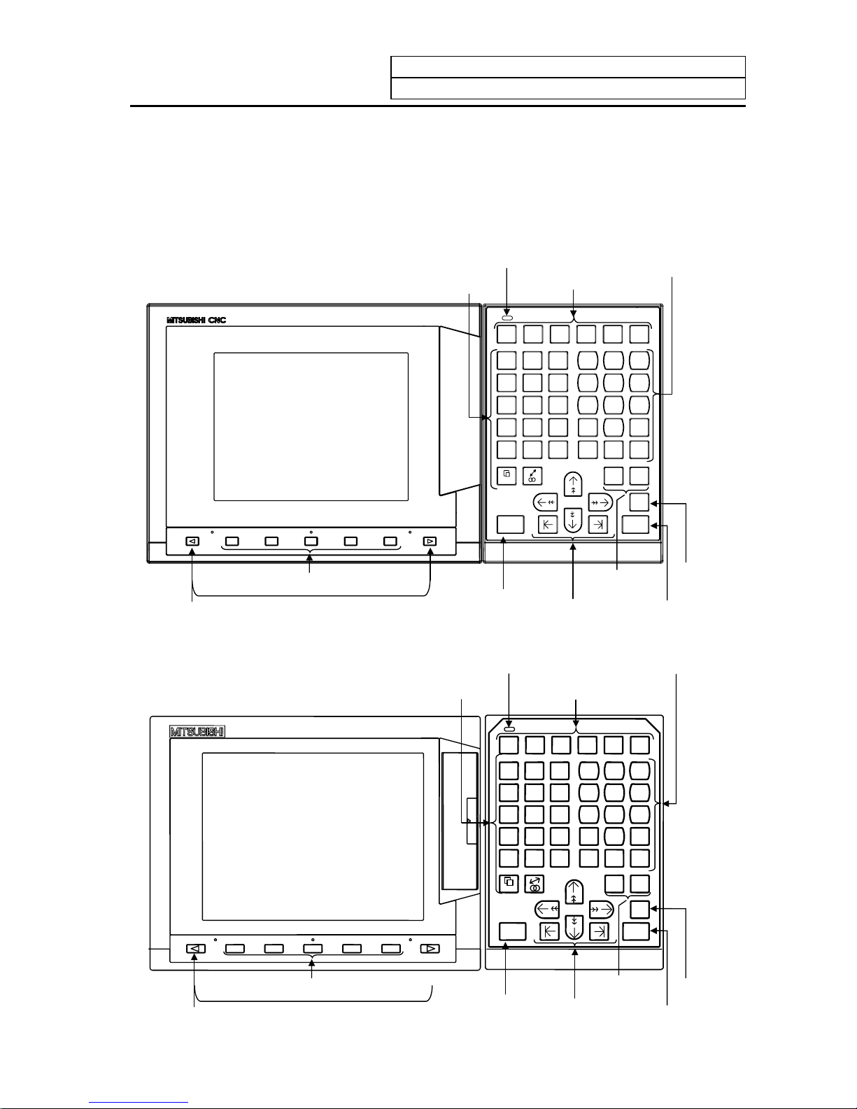
The setting and display unit consists of a display unit, keys, and menu keys, as illustrated below:
(1) Appearance of the Setting and Display Unit (For E60)
MONITOR
TOOL
PARAM
EDIT
MDI
DIAGN
IN/OUT
SFG F0
OANBG
C
XUYVZ
W
FEDLH
!
PIQJR
K
M(S)T
[
EOB
]
=#/
*
-
+
.
,
789
456
123
0
SP
DELETE
INS
C.B
CAN
SHIFT
INPUT
CALC
RESET
?
READY
Data correction
keys
Input key (calculation)
Shift key
Menu keys
Reset key
Cursor keys
Setting keys
READY LED
Function selection keys
Page keys
A
lphabetic character,
numerical character,
and symbol keys
(2) Appearance of the Setting and Display Unit (For E68)
READY
MONITOR
TOOL
PARA M
EDIT
MDI
DIAGN
IN/OUT
SFG F0
9
6
3
・
8
5
2
7
4
1
,
-
+
0
SP
= # /
*
EOB
]
DELETE
INS
C.B
CAN
SHIFT
INPUT
CALC
Z
W
G
C
H
!
R
K
T
[
Y
V
N
B
D
L
Q
J
S
)
X
U
O
A
F
E
P
I
M
(
RESET
?
Page keys
Menu keys
Reset key
Cursor keys
Data correction
keys
Input key (calculation)
Shift key
A
lphabetic character,
numerical character,
and symbol keys
READY LED
Setting keys
Function selection keys
Page 17

1. Setting and Display Unit Operation
1.2 Functions of Display Areas
I-2
1.2 Functions of Display Areas
Screen display is divided into the following four areas:
(1) Data display area
(2) Operation status mode and alarm message area
(3) Menu display area
(4) Setting area and key operation message area
.......Function.......
name
Data display area
Key operation message area..........
...Setting area........................................................................................................
...Operation status mode/alarm display area.........................................................
...Menu display area..............................................................................................
MONITOR 3. 1/4
Maximum
number
of pages
Pa
g
e number
Menu number
Function name
Menu 1 Menu 2 Menu 3 Menu 4 MENU
ST1 ST2 ST3 ST4 ST5 ST6 ST7 ST8
Operation mode
Operation status mode display and menu display
(during normal operation)
Menu 1 Menu 2 Menu 3 Menu 4 Menu 5
Alarm 1 (19 characters)
A
larm message display (during alarm occurrence
)
Alarm 2 (19 characters)
This is displayed when 6 or more
menus exist.
The selected menu is reversedisplayed.
A
larm is highlighted and message
(warning) is normally displayed.
Page 18
1. Setting and Display Unit Operation
1.2 Functions of Display Areas
I-3
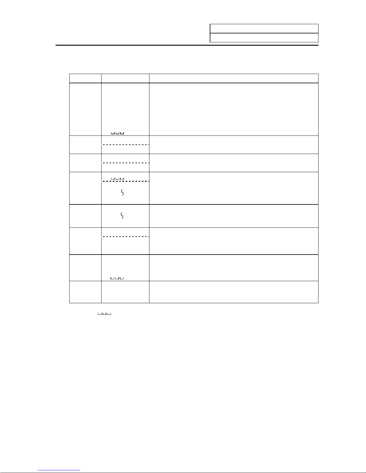
Explanation of operation status display
Position Display symbol Explanation
ST1 EMG During emergency stop
RST During reset
LSK When paper tape reader is in label skip state
HLD During feed hold stop
STP During single block stop
Normal operation state other than the above
ST2 mm Metric command
in. Inch command
ST3 ABS Absolute command mode G90
INC Incremental comman d mod e G91
ST4
This indicates that subprogram is not executed.
SB1
SB8
Machining program execution is controlled according to subprogram
data. Each value of 1 to 8 indicates the subprogram depth.
ST5
G54
G59
Selection of the workpiece coordinate system is indicated.
ST6 G40 Tool radius compensation cancel state
G41 During tool R compensation (left)
G42 During tool R compensation (right)
ST7 fix Fixed cycle is being executed.
PR State in which power must be rebooted to validate set parameter.
State other than the above.
ST8
(Note 1)
denotes blank display.
Page 19
1. Setting and Display Unit Operation
1.3 Screen Transition Diagram
I-4
1.3 Screen Transition Diagram
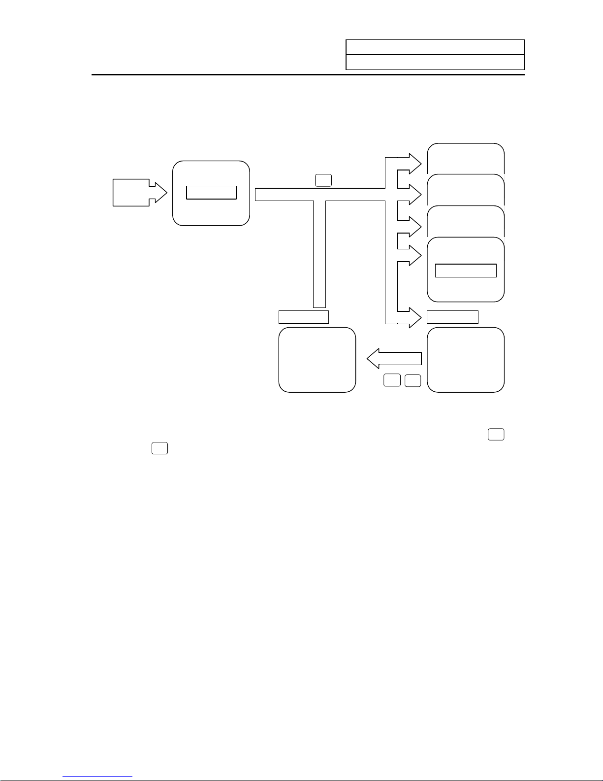
1.3.1 Screen Transition when Power Is Turned ON
MONI-
TOR
etc.
Power ON
O··1234 N12345
X -12000.000 M3
Y -3400.000 S100
Z -560.000 T12
N1
N2
MONITOR 1
Blank screen
Title screen
SHIFT
C.B
CAN
Display scree n
(1) When the power is turned ON, the "Title" screen is displayed. To select a display screen on the
"Title" screen, press the corresponding "function selection" key.
(2) To select a blank screen on a display screen, select the "MONITOR 1" screen and press
SHIFT
key,
then
C.B
CAN
key.
To select a display screen on the "blank screen", press the corresponding "function selection" key.
Page 20
1. Setting and Display Unit Operation
1.3 Screen Transition Diagram
I-5
1.3.2 Screen Transition Diagram (Lathe system)
MDI
MONITOR
POSITION COORDINATE
COMMAND
MODAL
INFORM.
TIME
PLC
SWITCH
COMMON
VARIABLE
LOCAL
VARIABLE
PROGRAM
SEARCH
TOOL
PARAM
NOSE-R
TOOL
LIFE
DATA
TOOL TIP
OFFSET
TOOL
DATA
I/O BASE
PARAM
SETUP
PARAM
BACKUP
SERVO
PARAM
SPINDLE
PARAM
BASE
SPEC.
PARAM
AXIS
SPEC.
PARAM
MACRO
FILE
PSW
MC-ERR.
CMP.
PLC
TIMER
#1000
#9000
#2000 #2200 #3000
#4000,#5000 #6000 #7000 #7000
The setting can be displayed when SETUP
PARAM is selected.
EDIT
MDI
MDI
EDIT
MDI-ENT
PROGRAM
SMALL
LARGE
FILE
SEARCH
DIAGN
IN/OUT
SPINDLE
MONITOR
PLC-I/F
ALARM
MESSAGE
SERVO
MONITOR
SERVO
DIAGNOSIS
ABS SERVO
MONITOR
A
BS. POSITION
SET
ERASE
FILE
INPUT
OUTPUT
SUPPORT
(Not used)
NC-DATA
SAMPLING
NSK-
TERMINAL
(Not used)
AUX-PRM
AUX-MON
PLC
TRACE
ADJUST
S-ANALOG
OPERATION
HISTORY
CONFIG
[MENU 1]
[MENU 2] [MENU 3] [MENU 4] [MENU 5] [MENU 6] [ME NU 7] [MENU 8]
#8000
EDIT
WORK
PROCESS
CONTROL
AXIS
BARRIER
TLM
COPY
IC-CARD
I/O
RESERCH
(Note) The 1st page of SUPPORT menu and the NSK TERMINAL screen are not used.
Page 21
1. Setting and Display Unit Operation
1.3 Screen Transition Diagram
I-6
SFG
PROGRAM
ERASE
TRACE
STEP
OPERATION
SEARCH
ERASE
CHECK
STANDARD
GRF
MODE
ROTATION
SCALE
F0
VISUAL
ANALYZER
LADDER
MONITOR
ON
OFF
PARAMETER
#1222/2
ON
OFF
PARAMETER
#6451/5 OFF
and #6451/0
Page 22
1. Setting and Display Unit Operation
1.3 Screen Transition Diagram
I-7
1.3.3 Screen Transition Diagram (Machining center system)
MONITOR
POSITION COORDINATE
COMMAND
MODAL
INFORM.
TIME
RESERCH
PLC
SWITCH
COMMON
VARIABLE
LOCAL
VARIABLE
PROGRAM
SEARCH
TOOL
PARAM
TOOL
LIFE
DATA
TOOL
OFFSET
T-
REGIST-
RATION
I/O BASE
PARAM
SETUP
PARAM
BACKUP
WORK
PROCESS
CONTROL
AXIS
BARRIER
TLM
BASE
SPEC.
PARAM
AXIS
SPEC.
PARAM
MACRO
FILE
PSW
MC-ERR.
CMP.
PLC
TIMER
#1000
#9000
#2000 #2200 #3000
#4000,#5000 #6000 #7000 #7000
EDIT
MDI
MDI
EDIT
MDI-ENT
PROGRAM
SMALL
LARGE
FILE
SEARCH
DIAGN
IN/OUT
SPINDLE
MONITOR
PLC-I/F
ALARM
MESSAGE
SERVO
MONITOR
SERVO
DIAGNOSIS
ABS SERVO
MONITOR
A
BS. POSITION
SET
SUPPORT
(Not used)
NC-DATA
SAMPLING
NSK-
TERMINAL
(Not used)
AUX-PRM
AUX-MON
ERASE
FILE
INPUT
OUTPUT
PLC
TRACE
ADJUST
S-ANALOG
OPERATION
HISTORY
CONFIG
[MENU 1]
[MENU 2] [MENU 3] [MENU 4] [MENU 5] [MENU 6]
#8000
SPINDLE
PARAM
SERVO
PARAM
MDI
EDIT
[MENU 7] [MENU 8]
The setting can be displayed when SETUP
PARAM is selected.
COPY
IC-CARD
I/O
(Note) The 1st page of SUPPORT menu and NSK TERMINAL screen are not used.
Page 23
1. Setting and Display Unit Operation
1.3 Screen Transition Diagram
I-8
SFG
PROGRAM
ERASE
TRACE
STEP
OPERATION
SEARCH
ERASE
CHECK
STANDARD
RANGE
GRF
MODE
ROTATION
SCALE
F0
VISUAL
ANALYZER
LADDER
MONITOR
ON
OFF
PARAMETER
#1222/2
ON
OFF
PARAMETER
#6451/5 OFF
and #6451/0
Page 24
1. Setting and Display Unit Operation
1.4 Screen Selection Procedure
I-9
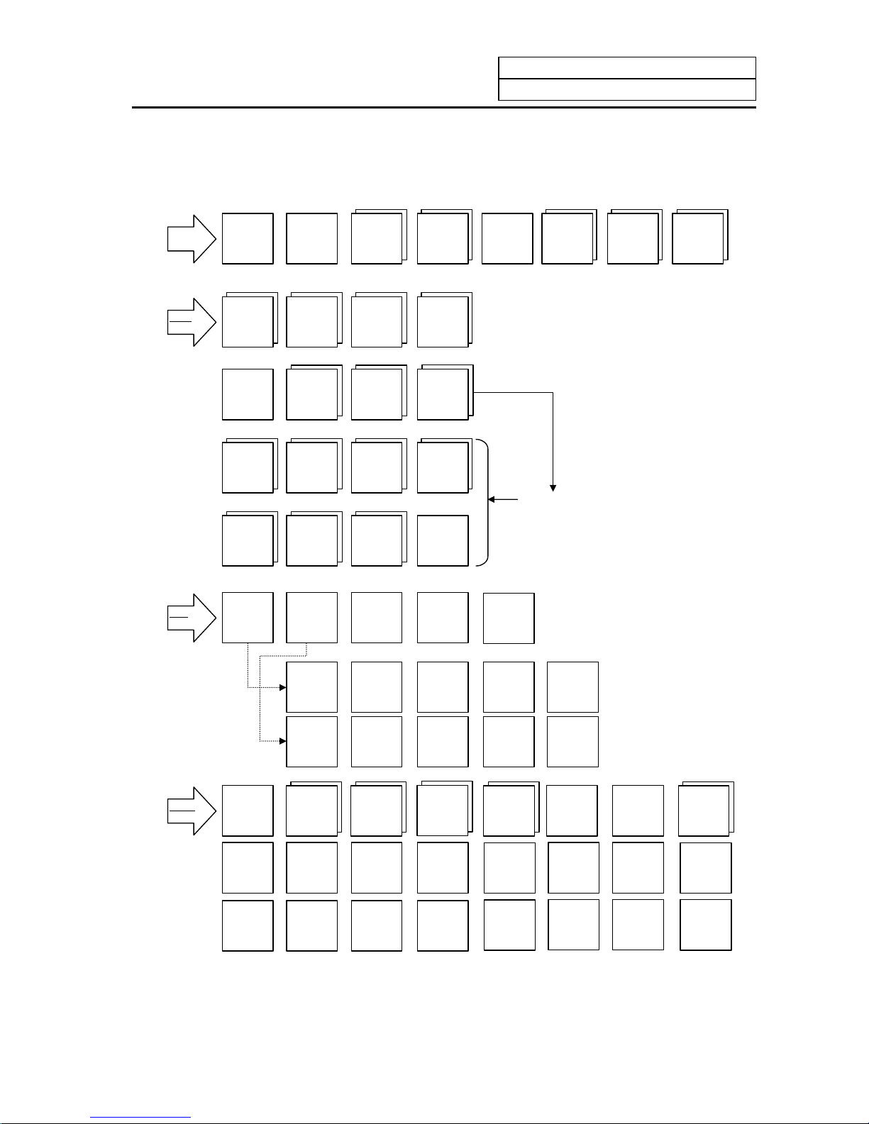
1.4 Screen Selection Procedure
The following operation methods are based on using the exclusive setting and display unit.
Select a screen according to the following procedure:
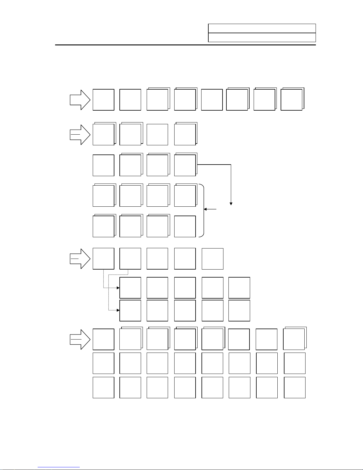
(1) Select a function screen by using the appropriate function key.
(2) Select a menu screen in the function by using the appropriate menu key.
(3) Select a page in the menu screen by using the page key.
FUNCTION
MENU
Page
First
page
Page Page
Menu 1 Menu 2 Menu 3 Menu 4 Menu 5 Menu 6 Menu 7 Menu 8
1.1
screen
2.1
screen
3.1
screen
4.1
screen
5.1
screen
6.1
screen
7.1
screen
8.1
screen
5.2
screen
6.2
screen
1.3
screen
6.3
screen
6.4
screen
4.2
screen
1.2
screen
2.2
screen
8.2
screen
Second
page
Third
page
Fourth
page
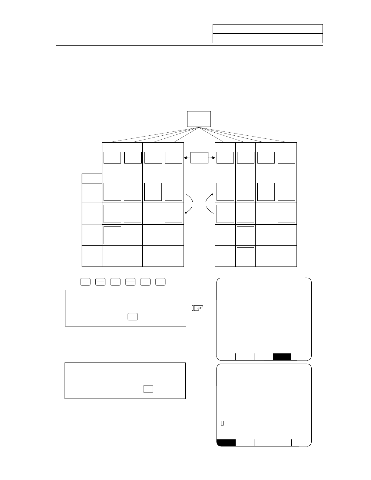
(1) Select a function screen.
MONI-
TOR
TOOL
PARAM
EDIT
MDI
DIAGN
IN/OUT
SFG
F0
Press the function selection key
corresponding to the function screen to be
displayed.
(Example)
Press the
MONI-
TOR
key.
1) The previously displayed menu screen is
displayed in the data display area.
2) Th e first display screen after power is turned
ON is the screen on the first menu.
If the same function selection key is again
pressed, a return is made to the first page
screen of the first menu.
(Example)
Again press the
MONI-
TOR
key.
POSI COORDI COMMAND SEARCH MENU
[PROGRAM SEARCH] MONITOR 4.1/4
O12345678 N12345-12
<SUB> O 1000 N 200-30
[PROGRAM FILE]
100 1500 50 000 1234 567
200 2000 70 000 2000 000
300 3000 1 23456 3000000
400 7000 2 00000 4000000
1234 10000 300000 5000000
[COL.BLOCK]
O N -
N20 G91 G28X0 Y0 Z0;
O( )N( )-( ) TAPE( )
[POSITION] 12/14 13:27 MONITOR 1
O12345678 N12345-12
<SUB> O 1000 N 200-30
S 12345
( 2000)
#1 T 1234
M 12
Fc 12000.00
G00 X-345.67 Y345.67;
T1234;
N100 S5000 M3;
N200 G00 Z-100;
X -12345 .678
Y 12345.678
Z 0.000
POSI COORDI COMMAND SEARCH MENU
Page 25
1. Setting and Display Unit Operation
1.4 Screen Selection Procedure
I-10
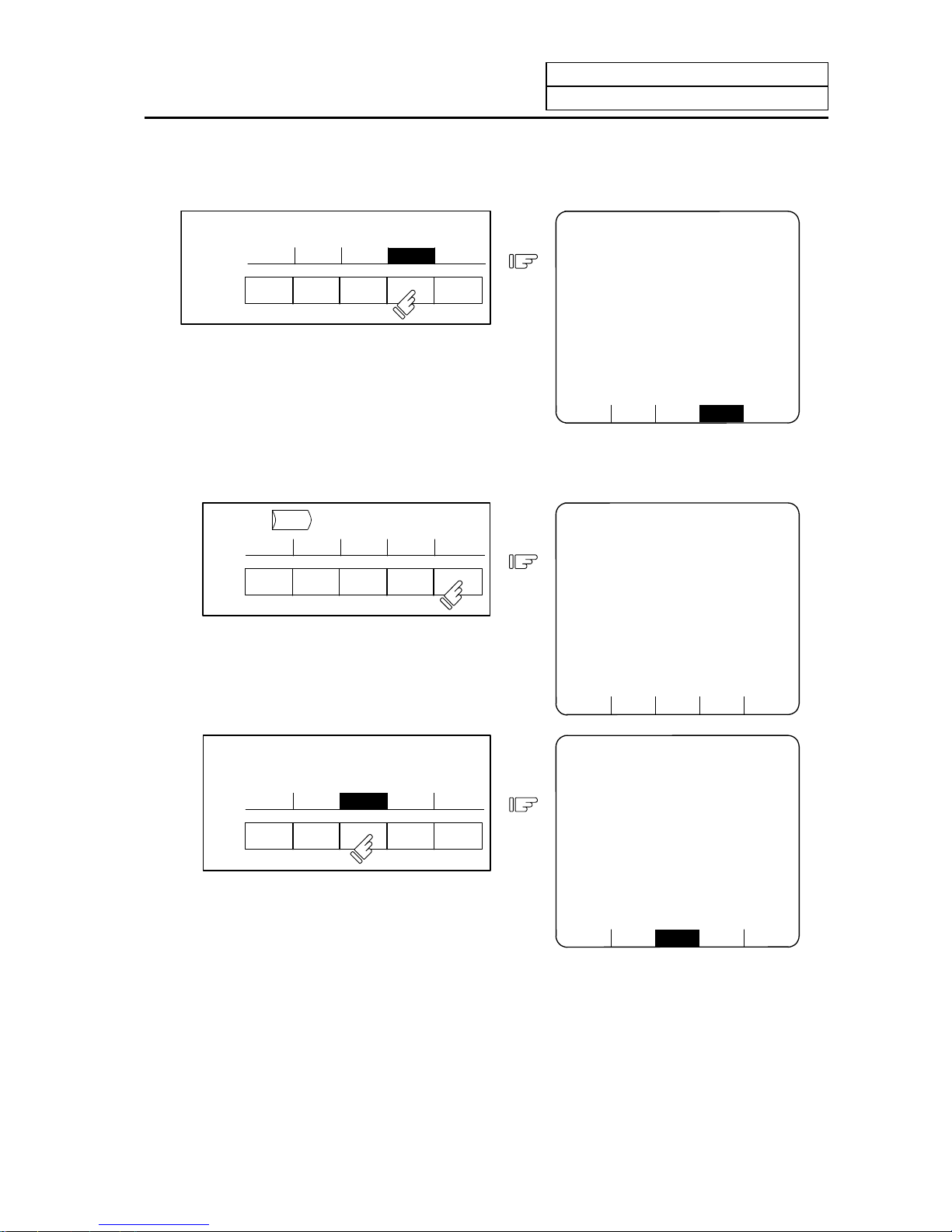
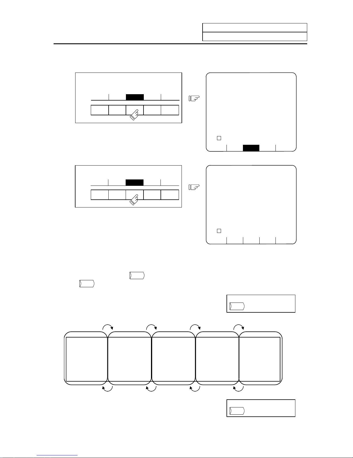
(2) Select a menu screen in the function.
Up to five menus are displayed at a time. When a menu key below the menu display is pressed,
the menu screen corresponding to the menu key is displayed.
Press the menu key corresponding to the menu
display.
Menu display
Menu key
POSI COORDI COMMAND SEARCH MENU
1) The selected menu screen is displayed
in the data display area.
2) The selected menu is highlighted in the
menu display area.
POSI COORDI COMMAND SEARCH MENU
[PROGRAM SEARCH] MONITOR 4.1/4
O12345678 N12345-12
<SUB> O 1000 N 200-30
[PROGRAM FILE]
100 1500 50 000 1234 567
200 2000 70 000 2000 000
300 3000 1 23456 3000000
400 7000 2 00000 4000000
500 10000 300000 5000000
[COL.BLOCK]
O N -
N20 G91 G28X0 Y0 Z0;
O( )N( )-( ) TAPE( )
When the rightmost menu in the menu display area is "MENU", it indicates that other menus than the
displayed menus exist. Make menu change by pressing the menu key below "MENU", then select the
menu screen to be displayed.
Press the
MENU
key.
POSI COORDI COMMAND SEARCH MENU
(1)
1) Only the menu display area is changed
and the remaining menu group is
displayed.
RESERCH PLC-SW COM-VAR LOC-VAR MENU
[PROGRAM SEARCH] MONITOR 4.1/4
O12345678 N12345-12
<SUB> O 1000 N 200-30
[PROGRAM FILE]
100 1500 50 000 1234 567
200 2000 70 000 2000 000
300 3000 1 23456 3000000
400 7000 2 00000 4000000
500 10000 300000 5000000
[COL. BLOCK]
O N -
N20 G91 G28X0 Y0 Z0;
O( )N( )-( ) TAPE( )
Press the menu key corresponding to the
menu display.
RESERCH PLC-SW COM-VAR LOC-VAR MENU
(2)
RESERCH PLC-SW COM-VAR LOC-VAR MENU
[COMMON VARIABLE] MONITOR 7.1/11
# 110
100 -123456.7890 111
101 12.3456 112
102 113
103 114
104 115
105 116
106 117
107 118
108 119
109
#( )DATA( )NAME( )
Page 26
1. Setting and Display Unit Operation
1.4 Screen Selection Procedure
I-11
When the screen selection menu is selected, the screen that " ↓ " mark is displayed after the menu
means that the operation menu exists.
Press the menu key corresponding to the
menu display.
T-OFSET T-DATA NOSE-R LIFE MENU
(1)
1) The selected menu screen is displayed
in the data display area.
2) The selected menu is highlighted and
" ↓ " mark is displayed after the menu.
T-OFSET T-DATA NOSE-R ↓ LIFE NENU
[NOSE-R] TOOL 3.1/4
#1 R 0.000 r 0.000 P 0
2 R 0.000 r 0.000 P 0
3 R 0.000 r 0.000 P 0
: : :
: : :
#( ) R( ) r( ) P( )
Press the menu key again.
(2)
T-OFSET T-DATA
NOSE-R ↓
LIFE MENU
1) The operation menu is displayed in the
menu display area.
+INPUT =INPUT RETURN
[NOSE-R] TOOL 3.1/4
#1 R 0.000 r 0.000 P 0
2 R 0.000 r 0.000 P 0
3 R 0.000 r 0.000 P 0
: : :
: : :
#( ) R( ) r( ) P( )
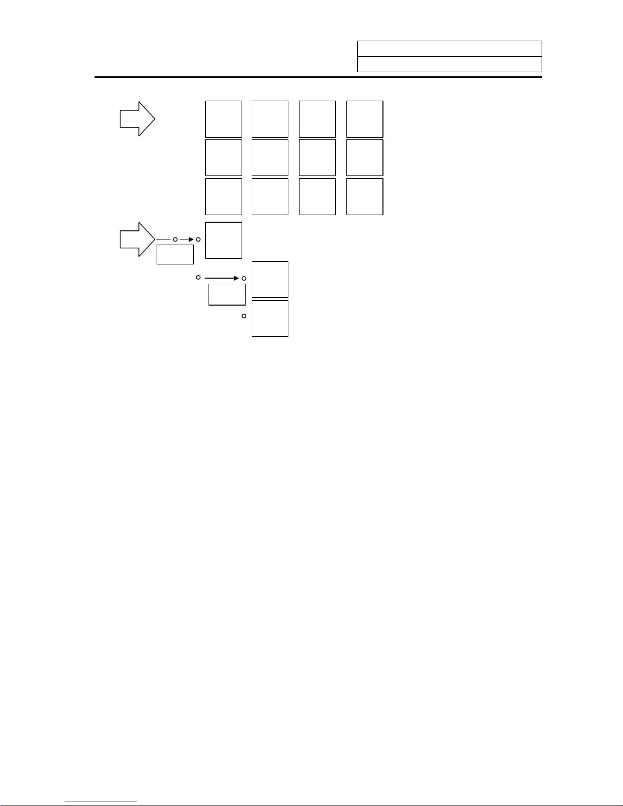
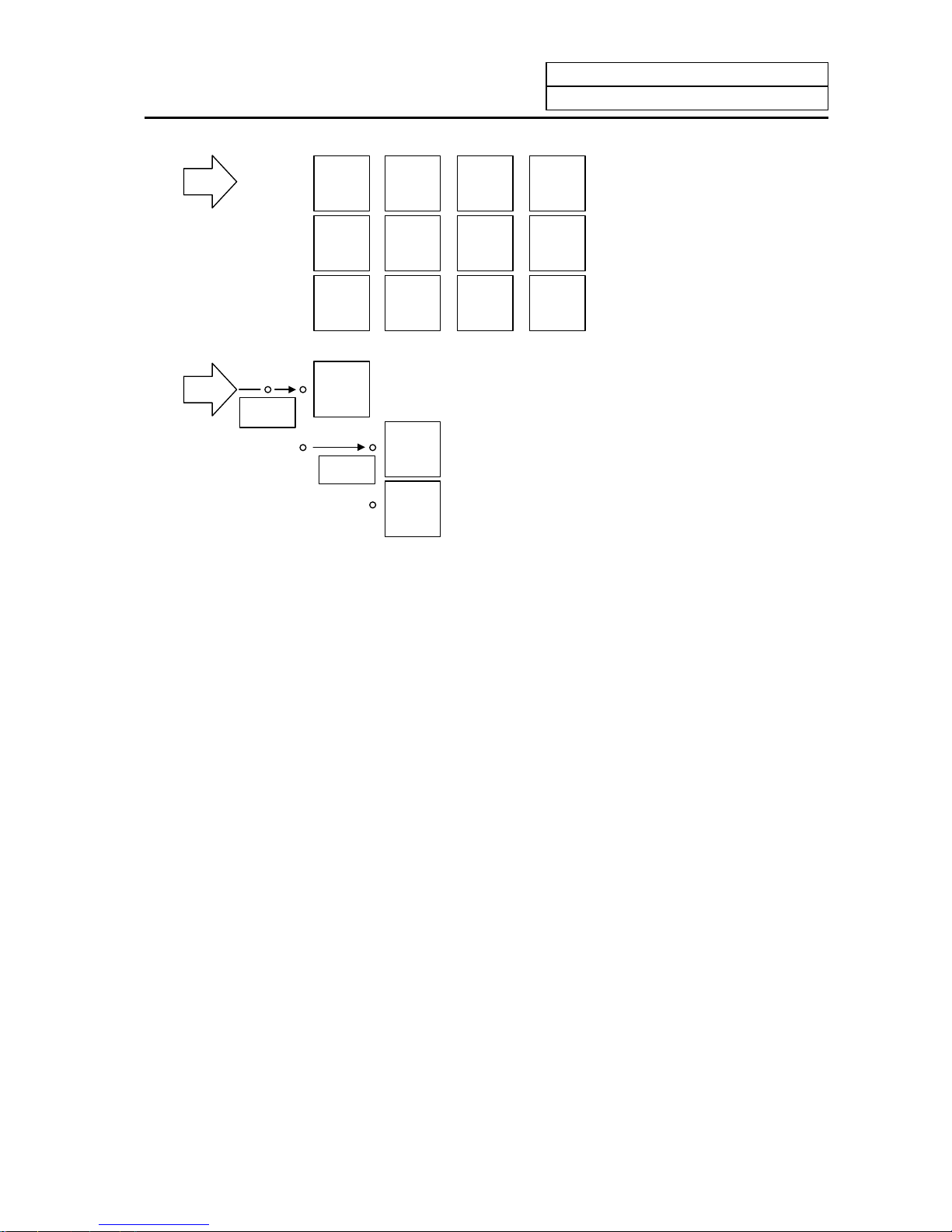
(3) Select a page in the menu screen.
When the menu screen contains a number of pages, feed pages by using the page key, the
rightmost page key (
NEXT
) is the "next page" screen selection key. The leftmost page key
(
BACK
) is the "previous page" screen selection key.
Using the rightmost key
NEXT
, feed page.
Using the leftmost key
BACK
,
feed page.
# 1 #1
#10 #20
#21 #31
#30 #40
#41 #51
#50 #60
First page Second page Third page Fourth page Fifth page
#81 #91
#90 #100
#61 #71
#70 #80
to to to to to to to to to to
Page 27
1. Setting and Display Unit Operation
1.5 Data Setting Method
I-12
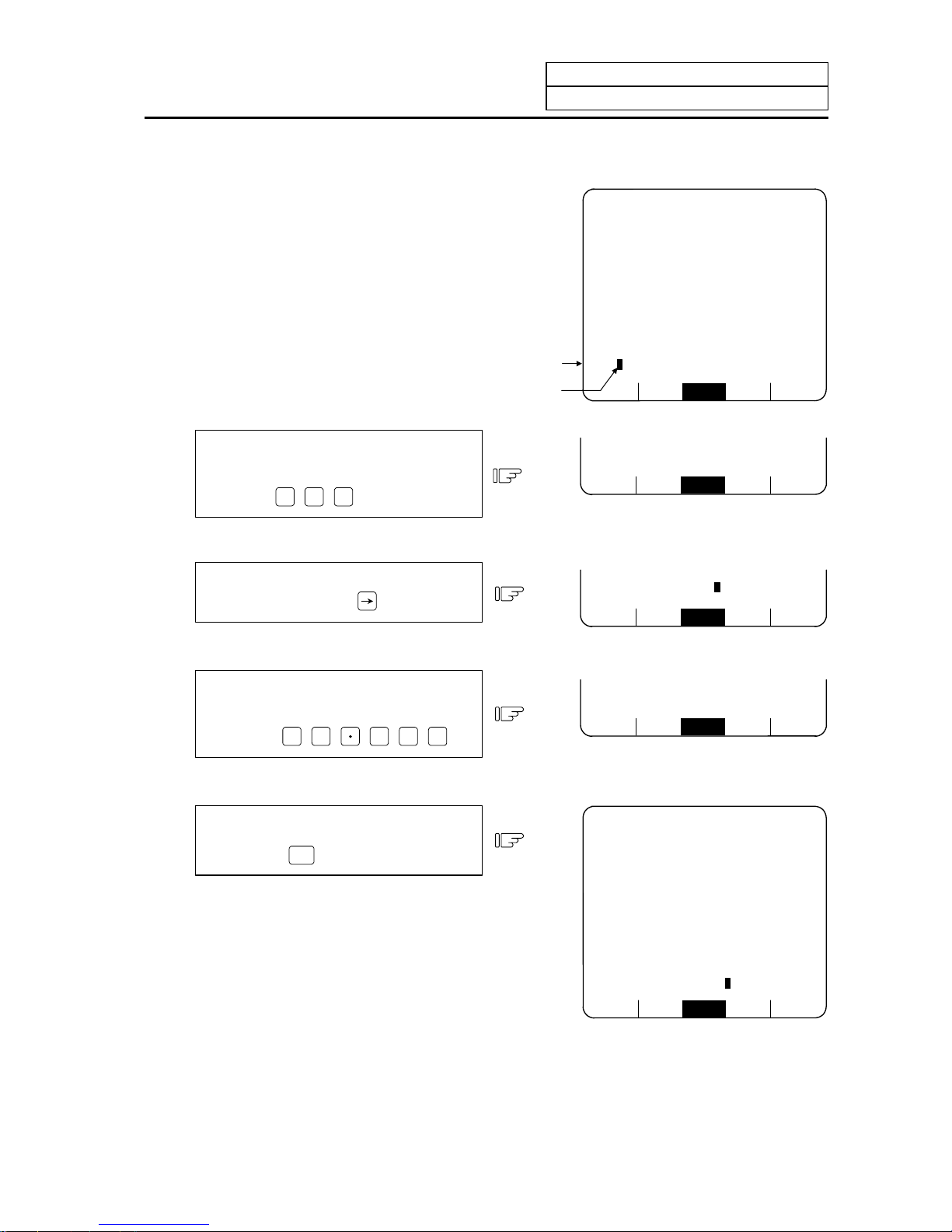
1.5 Data Setting Method
(1) Outline of data setting
The data setting method consists
mainly of the following steps:
(1) Enter the data number.
(2) Move the cursor.
(3) Press data keys.
(4) Press the INPUT key.
When a screen is selected, the cursor
is displayed in the right end within the
first parentheses in the setting area.
RESERCH PLC-SW COM-VAR LOC-VAR MENU
[COMMON VARIABLE] MONITOR 7.1/11
# 110
100 -123456.7890 111
101 12.3456 112
102 113
103 114
104 115
105 116
106 117
107 118
108 119
109
#( )DATA( )NAME( )
Data setting
area
Curso
r
(1) Enter the data number.
Enter the number of the data to be set by
using the numeric keys.
(Example)
To set data in #104, press
1
0
4
.
RESERCH P LC-SW COM-VAR LOC-VAR MENU
#( 104 )DATA( )NAME( )
(2) Move the cursor.
To move the cursor to the next
parentheses, press the
key.
RESERCH P LC-SW COM-VAR LOC-VAR MENU
#( 104 )DATA( )NAME( )
(3) Press data keys.
Seeing the data display area contents,
enter new data by using the keys.
(Example)
To change to 12.345, press
1
2
3
4
5
.
RESERCH P LC-SW COM-VAR LOC-VAR MENU
#( 104 )DATA( 12.345 )NAME( )
(4) Press the INPUT key.
Check the setup contents displayed in the
setting area and set the data in memory by
pressing the
INPUT
key.
1) Data setting processing is performed
according to the setting area contents,
and the result is displayed in the data
display area.
2) The data number in the setting area is
incremented by one, and the cursor is
displayed in the right end within the
second parentheses.
After the last data number is input, it is
not displayed. At this time, the cursor is
displayed in the right end of the first
parentheses.
RESERCH PLC-SW COM-VAR LOC-VAR MENU
[COMMON VARIABLE] MONITOR 7.1/11
# 110
100 -123456.7890 111
101 12.3456 112
102 113
103 114
104 115
105 116
106 117
107 118
108 119
109
#( 105)DATA( )NAME( )
Page 28
1. Setting and Display Unit Operation
1.5 Data Setting Method
I-13
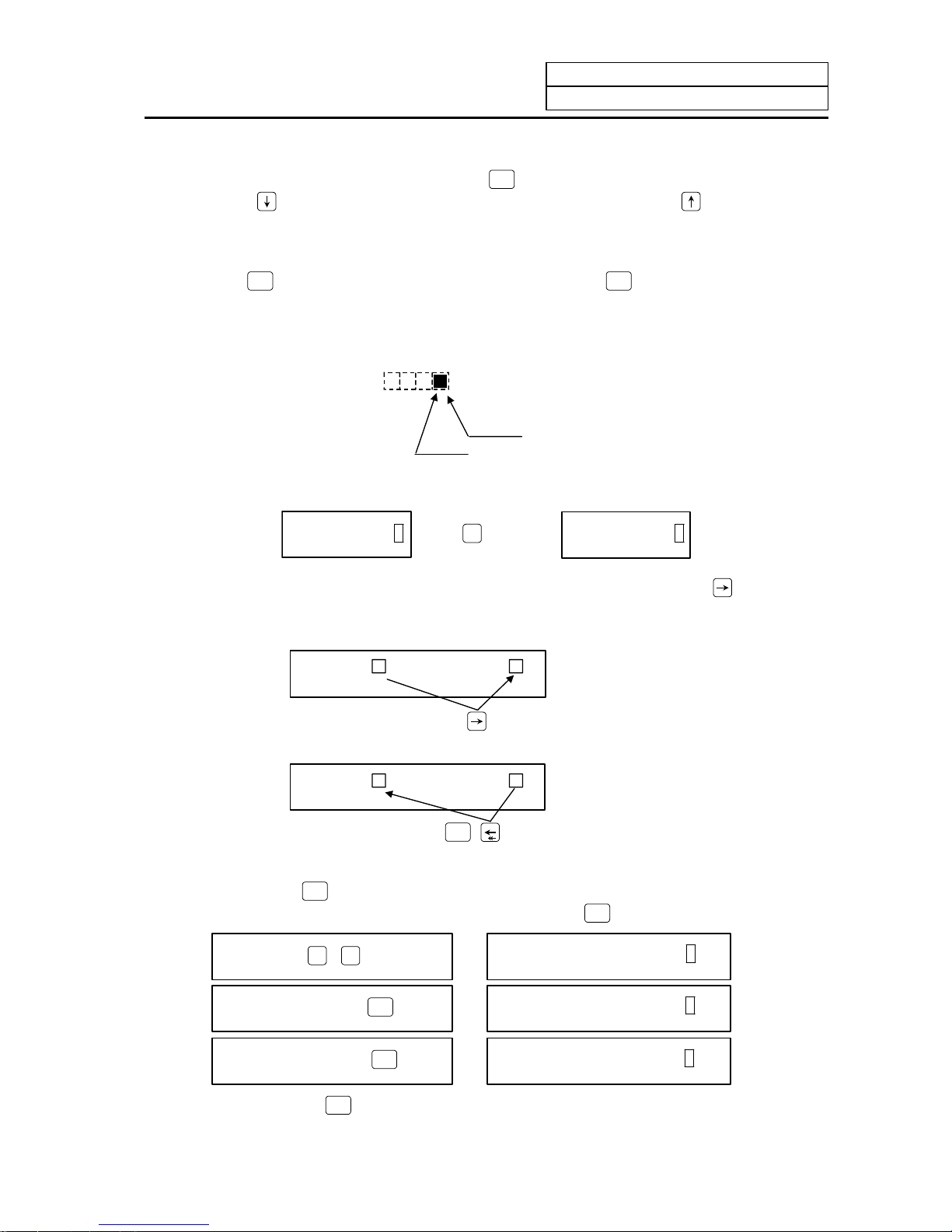
3) To consecutively set data, repeat (3) and (4).
4) To change the data number, press the
INPUT
key. The number is incremented by one. When
the
key is pressed, the number is incremented by one. When the
key is pressed, the
number is decremented by one. The data number can also be directly changed by moving th e
cursor to the data number setting area.
(Note 1) Data in the setting area is only displayed on the screen and is not set in memory until the
INPUT
key is pressed. If the screen is changed before the
INPUT
key is pressed, the data in the
setting area becomes invalid.
(2) Cursor control and operation examples
1) Data write into the display screen (by keying) is made at the position indicated by the cursor.
When the cursor is not displayed, keying is not effective.
Data ( )
Cursor
This position enables keying.
2) When any key is pressed, already displayed data is moved one column to the left and the dat a
corresponding to the key pressed at the cursor position is displayed.
DATA ( 12) When
3
is pressed, DATA ( 123)
3) If a number of parentheses exist in the data setting area, pressing the
key when the
cursor is in the right end within a parenthesis causes the cursor to move to the right end within
the next pair.
When the
key is pressed, the cursor is moved
to the right end within the next parentheses.
# ( ) DATA ( )
When the
SHIFT
key are pressed, the cursor is
moved to the preceding parentheses.
# ( ) DATA ( )
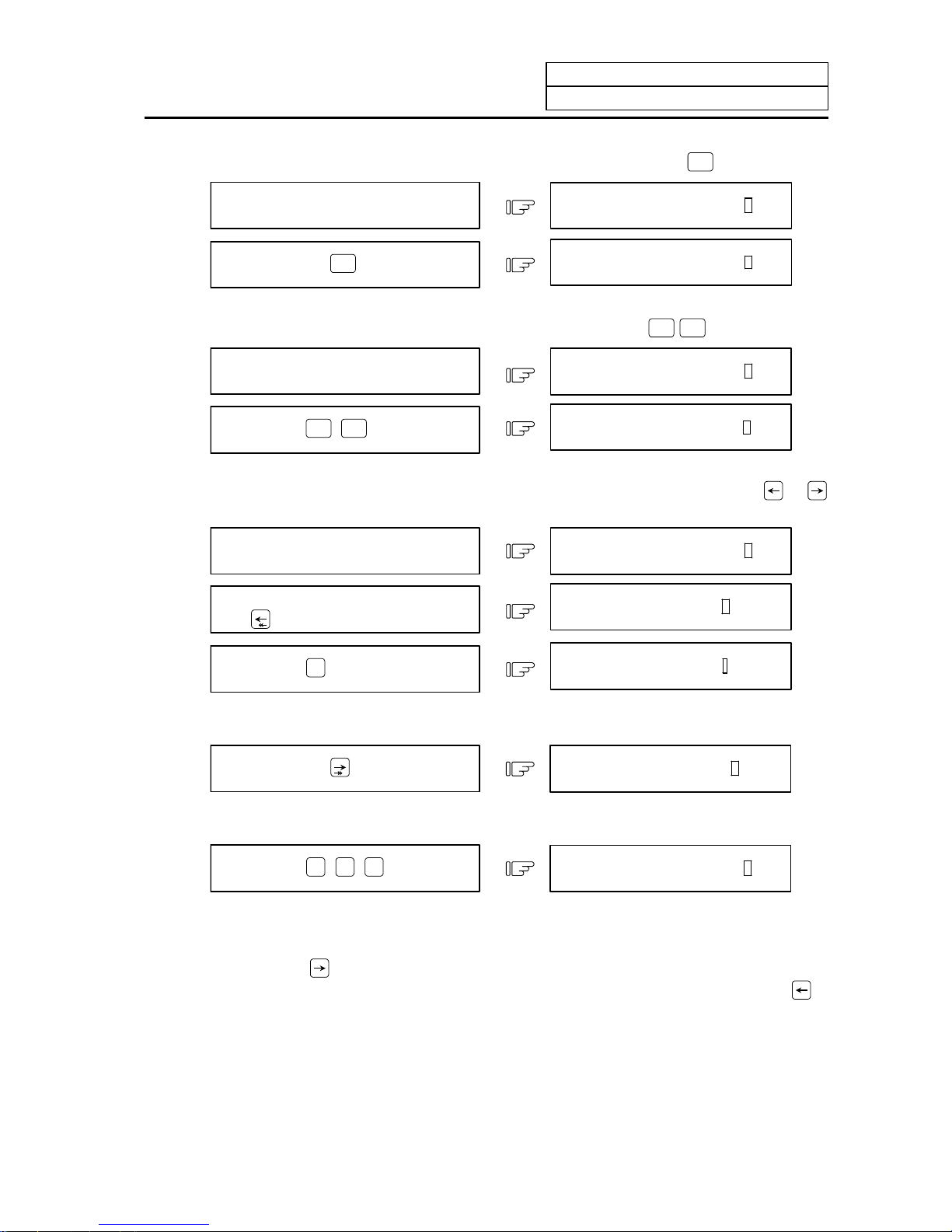
4) When the
DELETE
INS
key is pressed, the data at the cursor position is deleted. To cancel one
character entered by using any data key, etc., use the
DELETE
INS
key.
If you press
3
,
3
by mistake,
# ( 12) DATA ( 1233)
If you once press the
DELETE
INS
key,
# ( 12) DATA ( 123)
If you again press the
DELETE
INS
key,
# ( 12) DATA ( 12)
Each time the
DELETE
INS
key is pressed, one character of data at the cursor position is deleted and
the data to the left of the deleted character is moved one column to the right.
Page 29
1. Setting and Display Unit Operation
1.5 Data Setting Method
I-14
5) Data in parentheses where the cursor exists is erased by pressing the
C.B
CAN
key.
Display is made in the setting area as
shown in the right.
# ( 10) DATA ( 12.345)
If you press the
C.B
CAN
key,
# ( 10) DATA ( )
6) Data in all parentheses in the setting area is erased by pressing
SHIFT
C.B
CAN
.
Display is made in the setting area as
shown in the right.
If you press
SHIFT
C.B
CAN
,
# ( 10) DATA ( 12.345)
# ( ) DATA ( )
7) The cursor in parentheses is moved one column to the left or right by pressing the
or
key desired character of data entered by using the data keys can be corrected.
Display is made in the setting area as
shown in the right.
If you make successive four st rokes of
the
key,
If you press
3
,
# ( 10) DATA ( 12.345)
# ( 10) DATA ( 12.345)
# ( 10) DATA ( 13.345)
2 is corrected to 3 and the cursor is moved one column to the right.
If you press the
key,
# ( 10) DATA ( 13.345)
The cursor is only moved one column to the right.
If you press
0
SP
0
SP
0
SP
,
# ( 10) DATA ( 13.000)
The character at the cursor position is rewritten and the cursor is also moved one column to
the right. Data is corrected in sequence.
(Note 1) If
is pressed when the cursor exists in the right end within one parenthesis, the
cursor is moved to the right end within the following parenthesis part; if
is
pressed when the cursor exists in the left end within one parenthesis, the cursor is
moved to the right end within the preceding parentheses.
Page 30
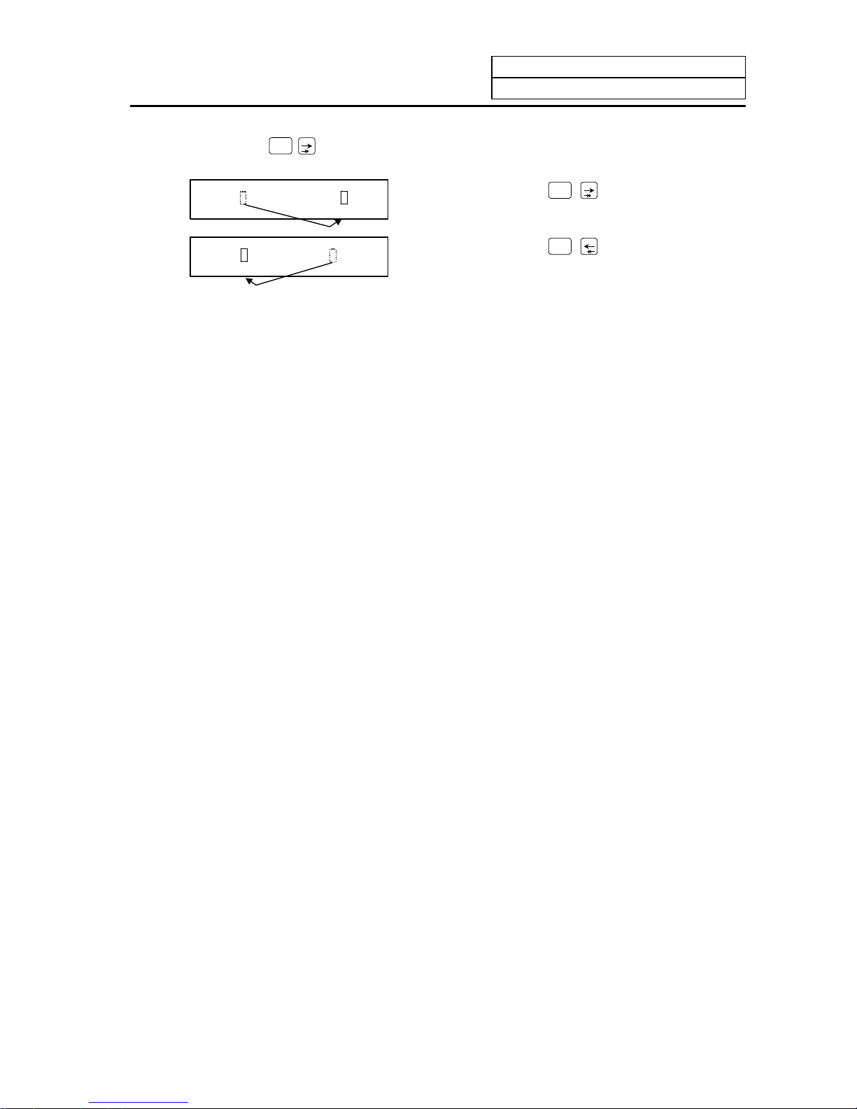
1. Setting and Display Unit Operation
1.5 Data Setting Method
I-15
8) When the
SHIFT
keys are pressed, the cursor is moved to the right end within the following
parentheses.
# ( 123 ) DATA ( 234)
If you press the
SHIFT
key, the cursor is
moved to the right end within the preceding
parentheses.
# ( 123) DATA ( 23 4)
If you press the
SHIFT
key, the cursor is
moved to the right end within the following
parentheses.
(3) Miscellaneous information
1) Data can also be set by other special methods. See the appropriate items. (For example,
manual numeric command setting is performed by the reverse display setting method.)
2) If an invalid key is pressed when data is set within parentheses, a "setting error" will occur at
input time and the data will not be accepted. Again set correct data from the beginning.
Page 31

1. Setting and Display Unit Operation
1.6 Screen Saver
I-16
1.6 Screen Saver
The screen saver function protects the display unit by turning OFF the screen after the time set in the
parameters has elapsed. The screen can also be turned OFF with key operations on the POSITION
screen.
The backlight OFF function turns OFF the backlight in order to extend the life of the LCD screen’s
backlight.
The screen can be turned ON by pressing any of the keys on the key operation panel.
(1) Turning the screen OFF
(a) Screen Saver
If there is no key operation or a screen display request signal input from the machine within the
time set in the parameter (#8078 Screen Saver Time), the screen will be turned OFF.
If the parameter is set to 0, the screen will not be turned OFF.
The screen can turn OFF by pressing the
SHIFT
and
C.B
CAN
keys on the POSITION screen. Even if
the parameter is set to 0, the screen can be turned OFF by pressing the
SHIFT
and
C.B
CAN
keys.
(Note) The screen will not be turned OFF even if the
SHIFT
and
C.B
CAN
keys are pressed on a
screen other than the POSITION screen.
(b) Backlight OFF
When the Screen Sever function works, the backlight turns OFF.
(2) Turning the screen ON
If a key is pressed or the screen display request signal is input while the screen is OFF, the
screen will turn ON. (If an LCD is used, the backlight will also turn ON.)
When a function select key is pressed, the screen will turn ON (the backlight will also turn ON for
an LCD), and each key function will be executed.
When alphanumeric or symbol key is pressed:
1
→ Only screen is turned ON
Z
→ Only screen is turned ON
* The following keys are also included.
(
INPUT
/
/
C.B
CAN
/
DELETE
INS
)
When a function select key is pressed:
MONI-
TOR
→ Screen turns ON and screen shifts
(Note) If a key is pressed or the screen display request signal is input while the screen is
ON, counting of the time to turn the screen OFF will restart.
Page 32

1. Setting and Display Unit Operation
1.6 Screen Saver
I-17
(3) Setting the parameters
# Item Contents Setup range (unit)
8078 Screen Saver Set the time to turn the screen OFF.
The screen saver will not turn ON if 0 is set.
0 to 60 (min)
0: Do not turn screen
OFF.
(4) Target display units
This screen saver function is valid with the following display units.
(a) 9-type CRT
(b) 7.2-type monochrome LCD
(c) 8.4-type color LCD
(Note1) The display unit in (a) is valid only when the screen is turned OFF by the
SHIFT
and
C.B
CAN
keys on the POSITION screen.
(Note2) The backlights are turned ON/OFF in the display unit s (b ) and (c).
(5) Precautions
(a) If the screen is turned OFF while keys can be operated on the EDIT screen, etc., and an
alphanumeric, symbol or INPUT key is pressed, the first key will be handled as that for
turning the screen ON. The key will not be input.
(b) If the function key, menu key, page key or system changeover key is pressed while the
screen is OFF, the screen corresponding to the pressed key will turn ON.
(c) The screen will not turn ON even if the reset key is pressed. However, if the screen display
request signal is input when the reset key is pressed, the screen will turn ON. Refer to the
instruction manual issued by each machine maker for details. Note that whether the screen
will turn ON when any of the machine operation board keys (other than the NC operation
board keys) is pressed will differ according to the machine specifications. Refer to the
instruction manual issued by each machine maker for details.
(d) Correspondence of
SHIFT
key.
The screen will not turn ON when just the
SHIFT
key is pressed.
Page 33

2. Monitor
I-18
2. Monitor
When the function selection key
MONI-
TOR
is pressed, the following menu appears:
POSI COORDI COMMAND SEARCH MENU
MONITOR menu display (No.5 to 8)
(No.1 to 4)
Menu selection keysPrevious page key Next page key
RESERCH PLC-SW COM-VAR LOC-VAR MENU
PROGRAM FILE
SEARCH
PROGRAM FILE
SEARCH
TIME
COM-VAR
MODAL
INFORM.
MONITOR menu display
No.1 to 4
POSITION
X M
Y S
Z T
PREVIOUS
PAGE
NEXT
PAGE
MENU
PLC-SW
COM-VAR
COORDI
POSITION, DIS
TO GO, WORK,
MACHINE
COMMAND
PROGRAM
DISPLAY
SEARCH
PROGERAM FILE
SEARCH
MONITOR menu display
No.5 to 8
PREVIOUS
PAGE
NEXT
PAGE
LOC-VAR
LOC-VAR
......
......
RESERCH
Page 34

2. Monitor
2.1 POSITION
I-19
2.1 POSITION
When the menu key
POSI
is pressed, the POSITION screen is displayed.
POSI COORDI COMMAND SEARCH MENU
[POSITION] 12/14 13:27 MONITOR 1
O12345678 N12345-12
<SUB> O 1000 N 200-30
S 12345
( 2000)
#1 T 1234
M 12
Fc 12000.00
G00 X-345.67 Y345.67;
T1234;
N100 S5000M3;
N200 G00Z-100.;
X -12345.678
Y 12345.678
Z 0.000
(4-axis pecifications)
The following can be performed on the POSITION screen:
(1) Full screen erase
(2) Origin set. The current value (POSITION) data of each axis can be set to 0.
(3) Manual numeric command. Miscellaneous function output of M, S, T, etc., can be set through the
screen.
Display item Explanation
12/14 13:27 The date and the time are displayed.
O12345678 N12345-12 The currently executing program n umber, sequence number, and
block number are displayed.
<SUB> O 1000 N 200-30 When a subprogram is being executed, the program number,
sequence number, and block number of the subprogram are
displayed.
Page 35

2. Monitor
2.1 POSITION
I-20
Display item Explanation
[POSITION]
X-12345.678
Y 12345.678
Z 0.000 #1
The relative value is the coordinate position using the machine zero
point as the reference.
The current position during execution and its abbreviation (if the
position is specific or is placed in specific state) are displayed.
#1~#4 (first to fourth reference point positions),
] [ (servo off state),
> < (axis removed state)
MR (mirror image) are displayed.
Whether the tool reference position (figure below (a)) or the current
position of the tool nose position (figure below (b)) that considers
offset, such as tool length offset amount or tool diameter
compensation amount, in the tool reference position is applied to
the display of the relative value can be selected with the parameter.
Workpiece offset
Machine
zero point
Workpiece
zero point
Relati ve value (a)
(Machine position)
Displayed by tool reference
position
Workpiece
coordinate
Current value B
Tool reference position
Tool nose position
Relati ve value (b)
Displayed by tool
nose position
Tool
The relative of the relation value counter display contents and the
parameters is as shown below.
0
Relative value
The compensation amount is considered
according to #1287 ext23/bit4,5 contents.
#1221 aux
05/bit7
1
Current value B
The counter of the POSITION screen
changes to the current value B.
S 12345 (2000)
T 1234
M 12
Fc 12000.00
The spindle rotation speed command value is displayed. The actual
spindle rotation speed is shown in ( ).
The tool command value is displayed.
The last four digits of the miscellaneous function command value
are displayed.
During interpolation feed, the speed in the current vector direction in
moving is displayed.
During independent axis feed, the speed of the axis with the highest
speed is displayed.
G00 X-345.67 Y345.67;
T1234;
N100 S5000M3;
N200 G00Z-100.;
Four blocks of the current program being executed are displayed.
The top block is an already executed block.
The subsequent three lines are the subsequent block program.
Page 36

2. Monitor
2.1 POSITION
I-21
2.1.1 Total Clear of Screen
If you do not use the unit for extended periods, clear the entire screen to prevent deterioration of the
display unit by the following procedures.
(1) Select 1st menu
POSI
on the MONITOR screen and press the
SHIFT
and
C.B
CAN
keys to clear
total
screen.
(2) If you want to display screen after clearing of total screen, press a function select key such as
MONI-
TOR
to display the screen you desire.
2.1.2 Position Display Counter Zero and Origin Zero
Counter Zero
The POSITION display only is set to zero and the absolute value data remains unchanged.
Origin Zero
This sets both POSITION display and absolute value data to zero.
It is equivalent to G92 X0 Y0 Z0 ;.
(Note1) Origin zero is valid only when #1123 origin is set to 0.
(Note2) Counter zero and origin zero are disabled in the current value B.
In the following operations, the
INPUT
key has
the counter zero function and the
C.B
CAN
key
has the origin zero (set zero) function.
Press the address key X.
1) The address indication corresponding
to the key is highlighted.
Press the
INPUT
key (counter zero)
or
C.B
CAN
key (origin zero).
1) The axis position data is set to zero and
the next axis name is highlighted.
2) By repeatedly pressing the
INPUT
key or
C.B
CAN
key, the position data of other axes
can be cleared to zero.
3) Upon completion of zero clear of final
axis, the display is no longer reversed.
4) If you press an axis address key
midway, the address of specified axis is
highlighted.
5) When you press a key other than axis
address key, the display is no longer
reversed.
X -12345.678
Y 1.234
Z 12.345
X -12345.678
Y 1.234
Z 12.345
X 0.000
Y 1.234
Z 12.345
X 0.000
Y 0.000
Z 12.345
Page 37

2. Monitor
2.1 POSITION
I-22
2.1.3 Manual Numeric Command (S, T, M)
You can easily execute spindle function S, tool function T and miscellaneous function M by operation
on the screen. Namely, you can key in S, T and M commands as if they were commanded by a
program.
(1) Conditions that allow manual numeric command
M, S or T command sequence is not under way. Even during automatic start or pause, for
example, the manual numeric command is available if above conditions are met.
(2) Operating procedures of manual numeric commands
1) Select the position display
POSI
menu screen.
2) Press the address key corresponding to the command. This causes the corresponding
commanded value display section to be highlighted and makes the system ready for input of
manual numeric command. The spindle function key is
S
, tool function key is
T
and
miscellaneous function key is
M
.
3) Key-in the numerical value to be input.
4) Press the
INPUT
key.
(Example) The procedures to execute S1200 by manual numeric command are given below. First
select POSITION display on MONITOR scre en.
On screen, last executed command
value is displayed.
Press the address key
S
.
1) The address corresponding to the
pressed key and numerical value
setting range are highlighted.
S 500
S
Set the numerical value by number
keys.
1
2
0
0
1) The set numbers are displayed
successively as highlighted.
S 1200
Press the
INPUT
key.
1) The S command is executed.
2) The reversed display on screen
returns to normal.
S 1200
Page 38

2. Monitor
2.1 POSITION
I-23
(3) Action to be taken when an erroneous numeric is set and the correct one is desired to be
set
There are two methods:
Method (1) While pressing the
DELETE
INS
key, delete the set digits one by one. Then, retry to enter
the correct digits.
Method (2) Retry the entry, beginning with pressing the address key corresponding to the
command.
Press
DELETE
INS
DELETE
INS
DELETE
INS
to delete the
erroneously set nu meri c.
(Example)
In this condition, the numeric is
desired to be replac ed by S1500.
S 1200
Method (1)
S 1
Enter
5
0
0
.
S 1500
Press address key
S
to return to
the initial status.
Method (2)
S
Enter
1
5
0
0
.
S 1500
(4) Setting/output range of manual numeric command
The setting and output range for the manual numeric command are indicated.
BCD Signed binary
M 0~9999
S ±99999
T 0~9999
Page 39

2. Monitor
2.1 POSITION
I-24
(Note 1) If the type is BCD output and a negative number is set, the positive value converted from it
will be output.
(Example) Manual numeric command
Output
M -100
M 100
(Note 2) If the number of digits specified in the command exceeds the setting range, the most
significant digit will be lost.
(Example)
M 1234
5
M 2345
Most significant di git is l o st.
1
(5) Other notes on operation
(1) When a minus command is set:
Before setting the numeric, press the
key.
(Example) If S-150 is specified:
Press address key
S
. Then, press
key
1
5
0
in order.
Press the
INPUT
key.
S-150
S 150
1) A minus value will be output, but a
positive value will display.
(2) When manual numeric command operation stops halfway:
If the operation is desired to be stopped before input after pressing the address key, press any
non-numeric key.
• If a manual numeric command address-key such as M, S, T is pressed, the previous
operation will stop. In this case, the next manual numeric command sequentially begins.
• If an axis address key (X, Y, or Z, etc.) is pressed, the manual numeric command will stop.
In this case, the origin zero or counter zero mode is then entered.
• If the
SHIFT
C.B
CAN
keys are pressed, the manual numeric command will stop. In this case,
the
POSITION screen is blanked.
• If one of the following keys is pressed, the operation will not stop:
1) Position display function key
MONI-
TOR
2)
key pressed before a numeric is set (will be processed as a minus command.)
3)
DELETE
INS
key when a numeric has been set (The set data will be deleted.)
(3) The macro interruption codes (M96, M97) and subprogram call codes (M98, M99) will not be
processed even if these codes are issued.
(4) No surface speed command is available.
In the constant surface speed mode, no command is processed, if specified.
Page 40

2. Monitor
2.1 POSITION
I-25
(5) The set data will be canceled if screen change is executed during manual numeric command
operation.
(6) If operations in which manual numeric commands are carried out (M, S, T keys) are attempted
when the manual numeric command protect function is valid, the error message "E05 NOT
ACCEPTABLE" will occur.
2.1.4 Displaying Automatic Operation Program
(1) Displaying the operation program during automatic operation
During memory, tape, or MDI operation, up to four blocks of the specified program are di splayed.
The block being executed or the completed block will display at the top line.
(2) Displaying the operation program after SEARCH
The head block of the operation searched program is displayed at the line of the next command.
(3) Displaying the operation program at branch to or at return from subprogram
When a branch command (M98) block is executed, the subprogram is immediately displayed.
When a return command (M99) block is executed, the main program is immediately displayed.
(4) Difference between one block of work program and one execution block
1) A block containing only EOB or only a comment statement is not interpreted as one execution
block. Instead it is processed as one block together with the next block.
2) A block that does not contain a movement command or MST command, such as a variable
command, is not interpreted as one execution block. Instead, the program up to the block
containing a movement command or MST command is handled in the same manner as one
block.
(Note) When a parameter "MACRO SINGLE" is ON, a variable command block is regarded as an
execution block.
Page 41

2. Monitor
2.2 COORDINATE
I-26
2.2 COORDINATE
When the menu key
COORDI
is pressed, the COORDINATE screen is displayed.
POSI COORDI COMMAND SEARCH MENU
[COORDINATE] O12345678 N12345-12 MONITOR2 2.1/2
<SUB>O 1000 N 200-30 Fc 0.00 WORK COUNT 1300/ 30000
N1 G00 X-345.678; [POSITION] [WORK (G54)] [MACHINE]
N2 T1234; X1 100.000 X1 100.000 X1 100.000
N3 S5000 M3; Y1 200.000 Y1 200.000 Y1 200.000
N4 G00 Z-100; Z1 300.000 Z1 300.000 Z1 300.000
N5 G01 X100. F500;
N6 Y100.;
N7 G02 X200. R200.;
[DIS TO GO] [NEXT]
SPINDLE 0 50 100 X1 100.000 X1 100.000 S
5000
110% Y1 200.000 Y1 200.000 ( 2000)
Z1 300.000 Z1 300.000
Z-AX 0 50 100
80% T 1234
STP mm ABS G40 G54 MEMOR
Y
M
12
Display item Explanation
O12345678 N12345-12 The currently executing program number, sequence number, and
block number are displayed.
<SUB> O 1000 N 200-30 When a subprogram is being executed, the program number,
sequence number, and block number of the subprogram are
displayed.
[POSITION]
X -345.678
Y 345.678
Z 0.000#1
The current position during execution and the status abbreviation of
the axis are displayed.
The status symbol is the same as the display on the POSITION
screen.
Workpiece offset
Machine
zero point
Workpiece
zero point
Relati ve value (a)
(Machine position)
Displayed by tool reference
position
Workpiece
coordinate
Current value B
Tool reference position
Tool nose position
Relati ve value (b)
Displayed by tool
nose position
Tool
Page 42
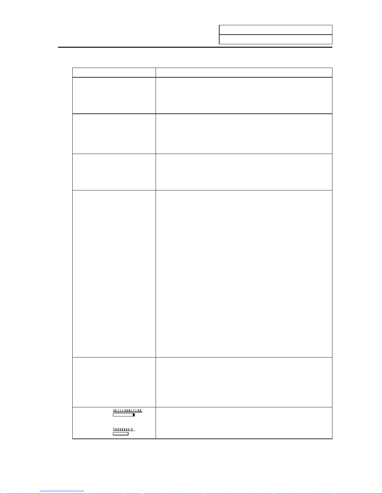
2. Monitor
2.2 COORDINATE
I-27
Display item Explanation
[WORK (G54)]
X -345.678
Y 345.678
Z 0.000
G54~G59, P1~P48 workpiece coordinate system modal numbers
and the workpiece coordinates in the workpiece coordinate system
are displayed.
[MACHINE]
X -345.678
Y 345.678
Z 0.000
The coordinate of each axis in the basic machine coordinate system
in which the unique position determined depending on the machine
is used as the zero point are displayed.
[DIS TO GO]
X 0.000
Y 0.000
Z 0.000
The remaining distance of the move command being executed
(incremental distance from the current position to the end point of
the block) is displayed during automatic operation start busy or
pause busy
[NEXT]
X1 0.000 S 5000
Y1 0.000 ( 2000)
Z1 0.000
T 1234
M 12
This displays the command contents of the block executed after the
block currently in execution during automatic operation.
The following display items can be selected according to setting the
parameters. (Note1)
[MST]
The spindle rotation speed command value is displayed. The actual
spindle rotation speed is shown in ( ).
The tool command value is displayed.
The last four digits of the miscellaneous function command value
are displayed.
[POSITION B]
Tool nose position coordinate that is considered tool length offset
and tool diameter compensation can be displayed in workpiece
coordinate.
Tool length offset and tool diameter compensation amount that are
considered depend on tool (T) designation or the currently selected
tool No. that is input from the external source.
[MANUAL IT]
The amount moved with the manual mode while the manual
absolute switch was OFF is displayed.
The manual interrupt amount can be selected for the counter value
displayed on the coordinate value screen using parameter.
N1 G00 X-345.678 Y345.678;
N2 T1234;
N3 S5000 M3;
N4 G00 Z-100;
N5 G01 X100.F500;
N6 Y100.;
N7 G02 X200.R200.;
The current work program being executed is displayed.
This is the same as the POSITION screen display.
SPINDLE
Z-AX
The spindle load and Z axis load can be displayed as a bar graph,
using the user PLC.
Page 43

2. Monitor
2.2 COORDINATE
I-28
Display item Explanation
WORK COUNT: /
Workpiece count
Max. workpiece count
Workpiece count :
Indicates count data of the number of workpieces.
Workpiece count Max. value :
The max. workpiece value set in #8003 WRK LIMIT value is
displayed.
Display range: 0~999999
(Note1) The type of position counter to display can be selected with the base specification parameter
(#1137 Cntsel).
Counter
Parameter
#1137 Cntsel
Left Right
00 or 10 MST
01 or 11 Next command
02 or 12 Current value B
03 or 13
Next command
Manual interrupt amount
20 MST
21 Next command
22 Current value B
23
Current value B
Manual interrupt amount
30 MST
31 Next command
32 Current value B
33
Manual interrupt
amount
Manual interrupt amount
Page 44

2. Monitor
2.2 COORDINATE
I-29
2.2.1 Correcting the Buffer
(1) Outline
During automatic operation (memory or tape mode) or MDI operation, a block stop can be applied,
and the next command can be corrected or changed.
When a program error occurs, the block in which the error occurred can be corrected without
resetting the NC, and operation can be continued.
(Note) When running a machining program from the external memory, even if the buffer is
corrected, the revisions are not reflected on the original program.
Pre-read
block
Execution
block
NC
opera-
tion
Buffer correction
Memory mode
MDI mode
Memory
MDI
Tape
or
IC card
Tape mode
Machine
control
(2) Details
(a) The next command can be corrected in the following two cases.
• When single block stop is applied, and there is a machining program containing a next
command to be corrected.
• During automatic operation, there is an error (program error) in the next command's
machining program, and the program is stopped.
(b) During memory or MDI operation, not only the displayed buffer data but also the memory and
MDI contents are corrected with the buffer corrections.
(c) If an error occurs in the preread block, the block in which the error occurred can be corrected.
(d) During IC card operation or tape operation, only the displayed buffer data can be corrected.
The IC card and tape contents cannot be changed.
(Note) The buffers on the second and third pages of the COORDINATE screen cannot be
corrected.
Page 45

2. Monitor
2.2 COORDINATE
I-30
(3) Operation method
During a single block stop or when a program error stop occurs, the buffer can be corrected with the
following operations, and operation can be continued.
(a)
(b)
* Buffer correction area (39 characters × 6 lines)
The normally executed program appears in this area. (Up to six lines will be displayed.)
←
Commands before previous command
←
Previous command
←
Command in execution
←
Next command and subsequent c ommands
:
:
N122 T1212;
N123 S1230 M3;
N124 G00 X68. Y201.;
N125 G01 X80. Y195. F50;
N126 Y150.;
N127 G02 X100. Y185. R20.;
:
:
[Buffer correction area in normal state]
Display
area
When correcting the buffer, the display changes so that the next command is displayed at the
head of the area, and the entire buffer correction area is highlighted. The cursor will initially
flicker at the head of the next command. The cursor can be moved freely within the buffer
correction area using the cursor keys. (6 lines)
N123 S1230 M3;
N124 G00 X68. Y201.;
N125 G01 X80. Y195. F50;
N126 Y150.;
N127 G02 X100. Y185. R20.;
N128 G01 X110.;
←
Next command and subsequent c ommands
[Buffer correction area during buffer correction]
Select the first page of the
COORDINATE screen.
Press the one of the cursor
keys (
,
,
,
) or tab
keys (
,
).
The buffer correction mode will be
entered, and the buffer correction area
will be highlighted.
Page 46

2. Monitor
2.2 COORDINATE
I-31
(c)
(d)
The buffer correction mode ends, and the corrected
data is written into to program.
If a program error has occurred, the error display
disappears.
(e)
The program execution resumes from the currently
stopped position.
(Example) An example of creating and executing the following program is given below.
If a program error (P62) occurs in the N125 block, the cause of the error is removed by
correcting the buffer.
N121 G28 X0 Y0;
N122 T1212;
N123 S1230 M3;
N124 G00 X68. Y201.;
N125 G01 X80. Y195.;
N126 Y150.;
N127 G02 X100. Y185. R20.;
N128 G01 X110.;
N129 G01 X120.;
N130 G01 X130.;
(a)
Start automatic operation.
1) A program error (P62) will occur
after N124 is executed.
N124 G00 X68. Y201.;
N125 G01 X80. Y195.;
N126 Y150.;
N127 G02 X100. Y185. R20.;
N128 G01 X110.;
N129 G01 X120.;
P62 F-CMD. NOTHING
Correct the program with the
same method as editing a
normal
prog
ram.
Press the
INPUT
key.
Confirm that the corrected
data is correct, and then
restart.
Page 47

2. Monitor
2.2 COORDINATE
I-32
(b)
Press the
key.
1) The head area of the program
being executed will change to the
buffer correction area when the
cursor key is pressed.
(The buffer correction mode will be
entered.)
2) The message "BUFFER EDIT" will
appear.
N125 G01 X80. Y195.;
N126 Y150.;
N127 G02 X100. Y185. R20.;
N128 G01 X110.;
N129 G01 X120.;
N130 G01 X130.;
BUFFER EDIT
P62 F-CMD. NOTHING
(c)
Insert "F50" at the end of the
N125 line.
BUFFER EDIT
P62 F-CMD. NOTHING
N125 G01 X80. Y195. F50.;
N126 Y150.;
N127 G02 X100. Y185. R20.;
N128 G01 X110.;
N129 G01 X120.;
N130 G01 X130.;
(d)
Press the
INPUT
key.
1) The buffer correction will end when
the INPUT key is pressed, and the
program being executed will
display.
(The buffer correction mode will be
canceled.)
2) The message "BUFFER EDIT" will
disappear.
3) The program error (P62) will
disappear.
N124 G00 X68. Y201.;
N125 G01 X80. Y195. F50.;
N126 Y150.;
N127 G02 X100. Y185. R20.;
N128 G01 X110.;
N129 G01 X120.;
(e)
Start automatic operation.
Execution will resume from the N125 block.
Page 48

2. Monitor
2.2 COORDINATE
I-33
(4) Supplement
(a) The key operations for making corrections during the buffer correction mode are the same as
the operations for editing the program. However, blocks other than those displayed in the buffer
correction area cannot be displayed and operated by feeding the page with the
NEXT
PAGE
or
PREVIOUS
PAGE
keys or by scrolling with the cursor keys. The page feed and scrolling operations will be
ignored.
Operation Buffer correction Program correction
Scroll Not possible Possible
Page feed/return Not possible Possible
Cursor movement Possible Possible
Character replacement Possible Possible
Character insertion Possible Possible
Character deletion Possible Possible
Block deletion Possible Possible
Page 49

2. Monitor
2.2 COORDINATE
I-34
(b) Even if the buffer is corrected, if the
INPUT
key has not been pressed, the corrections can be
returned to the original next command by pressing the
NEXT
PAGE
or
PREVIOUS
PAGE
key. The mode will
remain the buffer correction mode.
N124 G00 X68. Y201.;
N125 G01 X80. Y195.;
N126 Y150.;
N127 G02 X100. Y185. R20.;
N128 G01 X110.;
N129 G01 X120.;
P62 F-CMD. NOTHING
Press the
key.
N125 G01 X80. Y195.;
N126 Y150.;
N127 G02 X100. Y185. R20.;
N128 G01 X110.;
N129 G01 X120.;
N130 G01 X130.;
BUFFER EDIT
Insert F50. at the end of the N125
line.
N125 G01 X80. Y195.F50.;
N126 Y150.;
N127 G02 X100. Y185. R20.;
N128 G01 X110.;
N129 G01 X120.;
N130 G01 X130.;
BUFFER EDIT
Press the
NEXT
PAGE
or
PREVIOUS
PAGE
key.
1) Return to the state when buffer correction
is started.
N125 G01 X80. Y195.;
N126 Y150.;
N127 G02 X100. Y185. R20.;
N128 G01 X110.;
N129 G01 X120.;
N130 G01 X130.;
BUFFER EDIT
(Note1) The
NEXT
PAGE
and
PREVIOUS
PAGE
keys function to cancel the edited details during buffer correction, so
the page cannot be switched to the COORDINATE screen page 2 and following. Quit buffer
correction to change the page.
(Note2) In order to invalidate the buffer correction, press either the
NEXT
PAGE
or
PREVIOUS
PAGE
key, followed by
the
INPUT
key.
Page 50

2. Monitor
2.2 COORDINATE
I-35
(c) Buffer correction will be canceled if another screen is opened or reset is executed during the
correction. The corrected details will not be reflected.
(d) Operation cannot be started during buffer correction. The "M01 Operation alarm 0013" will
occur.
(e) If there is no ; (EOB) in the last block edited when
INPUT
is pressed, it will be added automatically.
N125 G01 X80. Y195.F50.;
N126 Y150.;
N127 G02 X100. Y185. R20.;
N128 G01 X110.;
N129 G01 X120.;
N130 G01 X130.
BUFFER EDIT
Press the
INPUT
key.
1) ";" is added to the end of the N130 block.
N124 G00 X68. Y201.;
N125 G01 X80. Y195. F50.;
N126 Y150.;
N127 G02 X100. Y185. R20.;
N128 G01 X110.;
N129 G01 X120.;
N130 G01 X130.;
Page 51

2. Monitor
2.2 COORDINATE
I-36
(f) When the buffer correction mode is entered, there may be cases when the program up to ;
(EOB) does not fit in and only part of the program is displayed because the last block displaye d
in the buffer correction area is long.
N124 G00 X68. Y201.;
N125 G01 X80. Y195.;
N126 Y150.;
N127 G02 X100. Y185. R20.;
N128 G01 X110.;
N129 G01 Y200.;
N130 G74 X120.0 Y100.0 Z-20.0 R-10.0
P2.,R0;
Press the
key.
1) "P2.,R0" of N130 is not displayed.
N125 G01 X80. Y195. F50.;
N126 Y150.;
N127 G02 X100. Y185. R20.;
N128 G01 X110.;
N129 G01 Y200.;
N130 G74 X120.0 Y100.0 Z-20.0 R-10.0
BUFFER EDIT
(Note) Handling when entire block is not displayed
The results will differ according to the state when
INPUT
key was pressed.
State Results
; (EOB) is not added to the end of
displayed data.
The section (P2.,R0;) not displayed will be the
continuing part of the displayed section.
; (EOB) is added to the end of the
displayed data.
The section (P2.,R0;) not displayed will become
separate block.
The N130 block is deleted with the
C.B
CAN
key.
During memory/MDI mode:
The section (P2.,R0;) not displayed will also be
deleted.
During tape mode:
Only the displayed section will be deleted, and
the section not displayed will be kept as a
separate block.
Page 52

2. Monitor
2.2 COORDINATE
I-37
(g) The number of characters that can be input at once will be the total of the number of characters
added (or deleted) with buffer correction and the number of characters in the other blocks
displayed in the correction area. The maximum number will be 234 characters (39 characters ×
6 lines). When adding data, characters exceeding the correction area's margin cannot be
added.
In this case, press the
INPUT
key and quit the buffer correction once. Then, correct the buffer
again. When buffer correction is started, a line return is added for each block and a space is
added for each word, so there will be more space for adding characters.
(Example) Add "N175 G74 Z–10.0 R–5.0 P2.0 ;" after N170.
N120 G02 X150.0 Y100.0 I25.0 J0.0;
N130 G02 X150.0 Y150.0 I0.0 J25.0;
N140 G02 X200.0 Y150.0 I25.0 J0.0;
N150 G02 X200.0 Y200.0 I0.0 J25.0;
N160 G02 X250.0 Y200.0 I25.0 J0.0;
N170 G02 X250.0 Y250.0 I0.0 J25.0;
N180 G02 X300.0 Y250.0 I25.0 J0.0;
Press the
key.
N130 G02 X150.0 Y150.0 I0.0 J25.0;
N140 G02 X200.0 Y150.0 I25.0 J0.0;
N150 G02 X200.0 Y200.0 I0.0 J25.0;
N160 G02 X250.0 Y200.0 I25.0 J0.0;
N170 G02 X250.0 Y250.0 I0.0 J25.0;
N180 G02 X300.0 Y250.0 I25.0 J0.0;
BUFFER EDIT
Insert "N175G74Z–10.0R;".
N130 G02 X150.0 Y150.0 I0.0 J25.0;
N140 G02 X200.0 Y150.0 I25.0 J0.0;
N150 G02 X200.0 Y200.0 I0.0 J25.0;
N160 G02 X250.0 Y200.0 I25.0 J0.0;
N170 G02 X250.0 Y250.0 I0.0 J25.0;N175G
74Z-10.0R;N180G02X300.0Y250.0I25.0J0.0;
BUFFER EDIT
Press the
INPUT
key.
N120 G02 X150.0 Y100.0 I25.0 J0.0;
N130 G02 X150.0 Y150.0 I0.0 J25.0;
N140 G02 X200.0 Y150.0 I25.0 J0.0;
N150 G02 X200.0 Y200.0 I0.0 J25.0;
N160 G02 X250.0 Y200.0 I25.0 J0.0;
N170 G02 X250.0 Y250.0 I0.0 J25.0;
N175 G74 Z-10.0 R;
N180 G02
X
300.0 Y250.0 I25.0 J0.0;
Page 53

2. Monitor
2.2 COORDINATE
I-38
Press the
key.
N130 G02 X150.0 Y150.0 I0.0 J25.0;
N140 G02 X200.0 Y150.0 I25.0 J0.0;
N150 G02 X200.0 Y200.0 I0.0 J25.0;
N160 G02 X250.0 Y200.0 I25.0 J0.0;
N170 G02 X250.0 Y250.0 I0.0 J25.0;
N175 G74 Z-10.0 R;
BUFFER EDIT
Insert "–5.0P2.0" at the end of the
N175 line.
N130 G02 X150.0 Y150.0 I0.0 J25.0;
N140 G02 X200.0 Y150.0 I25.0 J0.0;
N150 G02 X200.0 Y200.0 I0.0 J25.0;
N160 G02 X250.0 Y200.0 I25.0 J0.0;
N170 G02 X250.0 Y250.0 I0.0 J25.0;
N175 G74 Z-10.0 R-5.0 P2.0;
BUFFER EDIT
Press the
INPUT
key.
N120 G02 X150.0 Y100.0 I25.0 J0.0;
N130 G02 X150.0 Y150.0 I0.0 J25.0;
N140 G02 X200.0 Y150.0 I25.0 J0.0;
N150 G02 X200.0 Y200.0 I0.0 J25.0;
N160 G02 X250.0 Y200.0 I25.0 J0.0;
N170 G02 X250.0 Y250.0 I0.0 J25.0;
N175 G74 Z-10.0 R-5.0 P2.0;
N180 G02
X
300.0 Y250.0 I25.0 J0.0;
(h) If an error occurs in the preread block and the buffer correction mode is entered, the block in
which the error occurred will appear at the head of the area.
(i) The error cannot be canceled for a fixed cycle or compound fixed cycle that cannot be displayed.
Programs that cannot be displayed include:
• Fixed cycles
• Compound fixed cycles
• Machine maker macros (when base specification parameter #1166 fixpro=0)
• When running program No. 9000 to 9999 while the program display lock is valid (base
specification parameter #1122 pglk_c=1).
(j) Buffer correction is not possible for the subprogram in the IC card called by the M198
command.
Page 54

2. Monitor
2.2 COORDINATE
I-39
(k) Cases in which buffer cannot be corrected
The subprogram call command (M98) and return command (M99) will execute the next block to
be executed (subprogram head and return designation) with one automatic start. Thus, the
buffer for the subprogram's head and return destination blocks cannot be co rrected.
(Example 1)
O10
G28 XYZ
:
N10 G0 X50.;
M98 P100;
N11 G0 X100.;
N12 G0 X150.;
M02;
%
O100
N100 G01 Y10. F5000.;
N110 G01 Z10.;
M99;
%
If automatic start is executed when the block is stopped with N10, the N100 block will
be executed and will stop with N110. Thus, the buffer for N100 cannot be corrected.
If automatic start is executed when the block is stopped with N110, the N11 block will
be executed and will stop with N12. Thus, the buffer for N11 cannot be corrected. (Note
that if the buffer is corrected when the block is stopped before N10, then N11 can be
corrected.)
Normal buffer correction of the subprogram's head is not possible, as shown in the above example.
Note that if there is a G0/G1 command in the M98 block, the block will stop at that block. (Example:
G0M98P100;) If a block containing only the sequence No. is created at the head of the subprogram,
the program will stop at that block, so buffer correction of the following blocks is possible.
(Example 2)
O100
N1; ← Stops here
G01Y10.F5000;
M99;
%
Page 55

2. Monitor
2.2 COORDINATE
I-40
(6) Precautions
(a) When an error occurs during continuous operation, if the program pro cesses the variables, etc.,
in one step, the display will start not from the error block but instead from the head of the
variables in which there was a preread error block. Six lines of the program will be displayed.
Example) X100.;
← When the buffer correction mode is entered, these six lines will be
displayed.
X-10000000; ← Example when this block has a program error (P35).
If the macro block has seven or more lines, the block in which the program error occurred will
not be displayed.
(b) Edit lock C
When edit lock C is valid (base specification parameter #1121 edlk_c=1), buffer correction of
program numbers 9000 to 9999 is not possible. The "E16 EDIT LOCK C" error will occur.
When the base specification parameter #1122 pglk_c=1/2, buffer correction of program
numbers 9000 to 9999 is not possible. The "E16 EDIT LOCK C" error will occur.
(Note1) When either base specification parameter #1121 edlk_c or #1122 pglk_c is set, the
power must be rebooted.
(Note2) Buffer correction is possible for the machining program (program No. 9000 to 9999)
that is stored in either the IC card or tape, even if edit lock C is valid.
(c) Data protection key
Buffer correction is possible when data protection key 1 (*KEY1: Y238) is ON.
Buffer correction is possible when data protection key 2 (*KEY2: Y239) is ON.
Buffer correction is not possible when data protection key 3 (*KEY3: Y23A) is ON. The
message "DATA PROTECT" will appear.
(Note1) Buffer correction is possible for the machining program that is stored in either the IC
card or tape, even if data protection key 3 is valid.
(d) Edit lock B
When edit lock B is valid (control parameter #8105 EDIT LOCK B = 1), buffer correction of
program numbers 8000 to 9999 is not possible. The "E15 EDIT LOCK B" error will occur.
(Note1) Buffer correction is possible for the machining program (program No. 8000 to 9999)
that is stored in either the IC card or tape, even if edit lock B is valid.
#100=0;
#101=1;
#102=2;
#103=3;
#104=4;
#105=5
;
Page 56

2. Monitor
2.3 COMMAND
I-41
2.3 COMMAND
When the menu key
COMMAND
is pressed, the COMMAND screen is displayed.
This screen consists of three pages. It displays the execution program monitor, execution modal
monitor, and cumulative time data. Page switching is by pressing the
NEXT
PAGE
key or
PREVIOUS
PAGE
key.
2.3.1 Execution Program Monitor
This screen displays the active machining
program's execution blocks for monitoring.
POSI COORDI COMMAND SEARCH MENU
[COMMAND] MONITOR 3.1/3
O12345678 N12345-12 [WORK]
<SUB> O 1000 N 200-30 X 100.000
Y 200.000
Z 300.000
N10
・・・・・・・・・・・・・・・
;
N20
・・・・・・・・・・・・・・・・・・
;
N30 ;
N40 ;
N50 ;
N60 ;
N70 ;
N80 ;
N90 ;
N100 ;
Display item Explanation
O12345678 N12345-12 The currently executing program n umber, sequence number, and
block number are displayed.
<SUB> O1000
N200-30
When a subprogram is being executed, the program number,
sequence number, and block number of the subprogram are
displayed.
N10......... ;
N20............ ;
N30;
N90 ;
N100 ;
The current program being executed is displayed.
The cursor is moved to the top of the current block being executed.
When program execution reaches N90, the cursor is also moved to
the top of N90.
When the N100 block is executed, the N100 block is displayed
starting at the top of the screen and the cursor is also moved to the
top.
The read data is displayed also during tape running in the above
way.
[WORK]
X 100.000
Y 200.000
Z 300.000
The workpiece coordinates in the workpiece coordinate system
being currently executed are displayed.
Page 57

2. Monitor
2.3 COMMAND
I-42
2.3.2 Execution Modal Monitor
By switching the screen from the execution program's monitor screen (in the previous section) by
using the
NEXT
PAGE
key, the execution modal's monitor screen is displayed. This screen mainly
displays
the modal values of the active machining program for monitoring.
[M system] [L system]
POSI COORDI COMMAND SEARCH MENU
[MODAL INFORM.] MONITOR 3. 2/3
O12345678 N12345-12 [WORK]
<SUB> O 1000 N 200-30 X 0.000
G01 G18 G91 G94 Y 0.000
G21 G80 G98 G15 G64 Z 0.000
G67 G40.1 G97 G50.1 G43.1
G68 :R=
G50 :P= G54.1 :P48 G08 P0
G41: D1 = 30.000 ; 0.040 G05 :P 3
G43: H20 = 220.550 ; 0.240
: H =
FA 24000.00 S 12345 M 12345678
FM 1200.00 10
FS 0.0000 T 1234 35
B 1234 40
N300 G1 X-100.000 Y12345.678 F2000 ;
POSI COORDI COMMAND SEARCH MENU
[MODAL INFORM.] MONITOR 3. 2/3
O12345678 N12345-12 [WORK]
<SUB> O 1000 N 200-30 X 0.000
G01 G18 G G23 G98 Z 0.000
G21 G40 G80 G C 0.000
G64 G67 G69
G97 G14 G13.1 G43.1
G54.1:P48
Tx: –12.345
Tg : 12 Tw : 12 Tz: 10.000
V 0 Tc: 10.000
FA 24000.00 S 12345 M 12345678
FM 1200.00 10
FS
0.0000 T 1234 35
FE
0.0000 B 1234 40
N300 G1 X-100.000 Y12345.678 F2000 ;
Display item Explanation
O12345678 N12345-12 The currently executing program n umber, sequence number, and
block number are displayed.
<SUB> O1000
N200-30
When a subprogram is being executed, the program number,
sequence number, and block number of the subprogram are
displayed.
[WORK]
X 100.000
Y 200.000
Z 300.000
The workpiece coordinates in the workpiece coordinate system
being currently executed are displayed.
Same as the POSITION screen.
[MODAL INFORM.]
G01..........G94
G66.1.......G43
The modal state of the current G command being executed is
displayed.
(Note) Fixed cycle operation:
When a fixed cycle command is executed, the G command
in the fixed cycle control subprogram does not reflect the
G modal of the calling program.
G41:D1=30.000:0.040
G43:H20=220.550:0.240
(M system)
The tool radius compensation modal and offset number and wear
amount are displayed.
The tool length offset modal and offset number and wear amount
are displayed.
Page 58

2. Monitor
2.3 COMMAND
I-43
Display item Explanation
Tx: –12.345
Tz: 12.345
Ty: 10.000
(L system)
The total of the X axis, Z axis and additional axis' tool length and
wear compensation amounts for the tool being used is displayed.
Tg: 12
Tw: 12
(L system)
The tool length offset No. is displayed.
The wear compensation No. is displayed.
V (L system)
FA 24000.00
FM 1200.00
FS 0.0000
FE 0.0000 (L system)
S12345
T1234
M12345678 10 35 40
B1234
The surface speed modal value for the program command constant
surface speed control currently being executed is displayed.
The program command asynchronous feedrate modal value
currently being executed is displayed. (mm/min)
The manual feedrate is displayed. (mm/min)
The program command synchronous feedrate modal value
currently being executed is displayed. (mm/rev)
The thread lead command synchronous feedrate modal value
currently being executed is displayed. (mm/rev)
The modal value of the current program command S being
executed is displayed.
The modal value of the current program command T being
executed is displayed.
A maximum of four modal values of the current program command
M being executed are displayed.
The second miscellaneous function modal value of the current
program command being executed is displayed.
N300 G1X-100.234~ The current program block being executed is displayed.
Page 59

2. Monitor
2.3 COMMAND
I-44
2.3.3 Total Integrating Time Display
By switching the screen from the execution program's monitor screen by using the
NEXT
PAGE
key, the
TIME screen is displayed.
POSI COORDI COMMAND SEARCH MENU
[TIME] MONITOR 3.3/3
O12345678 N12345-12
<SUB> O 1000 N 200-30
# 1 DATE 99/12/14
2 TIME 13:27:59
3 POWER 9999:59:59
4 AUTO OP 0: 0: 0
5 AUTO STL 0: 0: 0
6 EXT TIME1 0: 0: 0
7 EXT TIME2 0: 0: 0
#( ) DATA( ) ( ) ( )
Display item Explanation
O12345678 N1234-12 The currently executing program number, sequence numbe r, and
block number are displayed.
<SUB> O1000 N200-30 When a subprogram is being executed, the program number,
sequence number, and block number of the subprogram are
displayed.
#1 DATE 99/12/14
2 TIME 13:27:59
3 POWER ON 9999:59:59
4 AUTO OP 0: 0: 0
5 AUTO STL 0: 0: 0
6 EXT TIME 1 0: 0: 0
7 EXT TIME 2 0: 0: 0
The date and time are set and displayed. year/month/day
hour : min : sec
The total integrating time in each operation state is displayed.
Page 60

2. Monitor
2.3 COMMAND
I-45
(1) TIME setting
Set the number, hour, minute, and second corresponding to the TIME to be set.
Set 3 in # ( ).
Set 0 in DATA ( ) ( ) ( )
Press the
INPUT
key.
#3 POWER ON 0: 0: 0
POSI COORDI COMMAND SEARCH MENU
# (3) DATA ( 0 ) ( 0 ) ( 0 )
DATE : Set date (set "YEAR" in last 2 digits of Gregorian calendar)
TIME : Set time in 24-hour mode.
POWER ON : Total integrating time of the time from control unit power ON to OFF.
AUTO OP : Total integrating time of the work time from AUTO STL button pressing in the
memory (tape) mode to M02/M30 or reset button pressing.
AUTO STL : Total integrating time during automatic starting from AUTO STL button pressing in
the memory (tape) mode or MDI to feed hold stop, block stop, or reset button
pressing.
EXT TIME 1 : Dependent on PLC sequence.
EXT TIME 2 : Dependent on PLC sequence.
(Note) Integration time (#3 POWER ON to #7 EXT TIME 2): When display reaches the
maximum value (9999:59:59), integration is stopped and the maximum value remains
displayed.
Page 61

2. Monitor
2.4 PROGRAM SEARCH
I-46
2.4 PROGRAM SEARCH
When the menu key
SEARCH
is pressed, the PROGRAM SEARCH screen is displayed.
The SEARCH screen enables you to call the program number, sequence number, and block number
for automatic operation from the machining programs registered in memory (or on paper tape or IC
card).
POSI COORDI COMMAND SEARCH MENU
[PROGRAM SEARCH] MONITOR 4. 1/4
O12345678 N12345-12
<SUB> O 1000 N 200-30
[PROGRAM FILE]
100 1500 50000 1234567
200 2000 70000 2000000
300 3000 123456 3000000
400 7000 200000 4000000
1234 10000 300000 5000000
[COLLATION BLOCK]
O N -
O( ) N( )-( ) COL.( ) TAPE(0)
Display item Explanation
O12345678 N12345-12 The currently executing program n umber, sequence number, and
block number are displayed.
<SUB>
O 1000 N 200-30
When a subprogram is being executed, the program number,
sequence number, and block number of the subprogram are
displayed.
[PROGRAM FILE]
100 1500 50000 1234567
200 2000 70000 2000000
300 3000 123456 3000000
400 7000 200000 4000000
1234 10000 300000 5000000
The numbers of the machining programs registered in memory are
listed.
The numbers ranging from 1 to 99999999 are displayed in the
ascending order.
If the number of the registered programs exceeds one page of
display, PROGRAM FILE is displayed extending across pages.
[COLLATION BLOCK]
O N -
The program position where compare stop is executed is displayed.
After MDI operation is executed, programs cannot be searched for unless reset is executed.
To restart from the middle of the program, search for the restart block, and then carry out MDI
operation to restore the modal state.
Page 62

2. Monitor
2.4 PROGRAM SEARCH
I-47
2.4.1 Memory Search
Any work program is called from the machining programs registered in memory before work.
Set the program number to be called, the sequence number, and block number. Set the tape search
setting area to 0. The initial state when power is turned ON is memory search.
Press the
INPUT
key.
O ( 1234) N ( 20) - ( ) COL.( ) TAPE(0)
SEARCH EXECUTION
O ( 1234) N ( 20) - ( ) COL.( ) TAPE(0)
[PROGURAM SEARCH] MONITOR 4. 1/4
O1234 N 20-0
<SUB> O 0 N 0-0
[PROGRAM FILE]
100
200
300
400
1234
[COLLATION BLOCK]
O N -
SEARCH COMPLETE
O( ) N( )-( ) COL.( ) TAPE(0)
1) A search is started.
2) When the specified program
number, sequence number, and
block number are found,
SEARCH COMPLETE message
is displayed.
The found numbers are displayed
in O and N. Data in the found
block is displayed in the work
program display ar ea .
Set the program number to be
called. Set the sequence number
and block number as required.
(
Example
)
To call O1234 N20 block,
O ( 1 2 3 4 ) N ( 2 0 ) - ( )
COL.( ) TAPE (0)
(Note 1) If one of the following operations is executed in the EDIT screen after memory search, the
system enters a status in which nothing is being searched. Operation is disabled at this time.
In this case, execute the search again.
• Deleting the program being searched.
• Deleting the sequence number for which the search was being executed.
• Deleting the block corresponding to the block number for which the search was being
executed.
(Note 2) One block which the control unit executes in one automatic start cycle can be searched in
this case. The block with ; (EOB) or sequence number only is not regarded as a one cycle
execution block. Axis movement command or control command such as M, S, or T is
contained in it.
Page 63

2. Monitor
2.4 PROGRAM SEARCH
I-48
2.4.2 Tape Search
If processing is desired to be executed from a halfway position on paper tape when running the
machining program using paper tape, the tape can be searched for the sequence number and other
information.
Before using the tape reader, match tape reader setting and control unit input/output parameter
setting. Set the input/output basic parameters and input/output device parameters on the DATA
IN/OUT screen.
Mount the paper tape on the tape reader. Then, select tape operation mode and execute the following
search:
(1) Set the target program number in O ( ). Set the target sequence number in N ( ). Set the target
block number in - ( ). Set "1" in TAPE ( ).
(2) Press the
INPUT
key.
(Example)
O ( 1 0 ) N ( 1 ) - ( )
COL.( ) TAPE( 1 )
O ( 10) N ( 1) - ( ) COL.( ) TAPE( 1)
SEARCH EXECUTION
O ( 10) N ( 1) - ( ) COL.( ) TAPE( 1)
[PROGURAM SEARCH] MONITOR 4. 1/4
O 10 N 1-0
<SUB> O 0 N 0-0
[PROGRAM FILE]
100
200
300
400
1234
[COLLATION BLOCK]
O N -
SEARCH COMPLETE
O( ) N( )-( ) COL.( ) TAPE(1)
1) A search is started. The paper
tape reader operates and paper
tape is run.
2) During search, the machining
program data being read is
displayed at the top of the setting
area. Message SEARCH
EXECUTION is displayed during
this period.
3) When the specified program is
found, the search completion
message is displayed.
The target numbers are displayed
at O and N, located at the top of
the screen. The data of the target
block is displayed in the
machining program's display
area.
Press the
INPUT
key.
(Note) If the tape contains a $ mark during tape operation, a program error (P32) will occur at the
$ mark.
Page 64

2. Monitor
2.4 PROGRAM SEARCH
I-49
(Supplements)
(1) Search starts in the position set in the tape reader. (In the label skip status, control jumps to
the first EOB.)
(2) After the search is completed, the searched block is read and the tape reader stops.
(3) If the NC is reset during search, the search stops. If the NC is reset after search is completed,
the unsearched status returns.
(4) If the specified block has not been found after the data to the EOR is read, the following
message is displayed: "E03 NB NOT FOUND"
If control parameter "% RWD (SEARCH)" is OFF, the tape will stop at the EOR of the program
end. If the parameter is ON, the tape will be rewound to the EOR of the program head and will
stop there.
(Note) Even if control parameter "% RWD (SEARCH)" is ON, the tape will not be rewound if
I/O DEVICE PARAM "REWIND CODE" has not been set correctly.
The rewind code depends on the I/O device used. Refer to the I/O device manual for
rewind code details.
(Example) When the tape was searched for N1 from a halfway position, the tape end was
reached before N1 was found. (When "% RWD (SEARCH)" is ON)
% ; N1G ; N2 ; N3 ; %
Position after rewind Search start position
Tape rewind
By pressing the
INPUT
key after rewind, the tape
is searched for N1.
Error "E03 NB NOT FOUND"
(5) If the target program number is not specified, the tape will be searched for only N and B. This
does not relate to the program numbers in the tape.
(6) If the
INPUT
key is pressed after normal tape search is completed and other information
including another NB is set, search will be executed. If a block stop status is entered after
search is completed and the automatic running status is entered by pressing the automatic
start button once, tape search will not be executed.
(7) After tape search is completed, "1" is retained in the setting field of TAPE ( ). Thus, the value
does not need to be set for each tape search. Only when memory search is desired to be
executed, set "0" in the setting field of TAPE ( ).
(8) The "LSK" display is cleared when the first EOB is read. It is displayed at reset or EOR read
time.
Page 65

2. Monitor
2.4 PROGRAM SEARCH
I-50
2.4.3 IC Card Search
Program search is carried out to execute a machining program from the IC card .
Before using the IC card, confirm that the file to be searched exists in the IC card.
Files that can be searched are in the ANSI text format, having the file name of "Program No. +
extension (.PRG)".
Mount the IC card. Then, select tape operation mode and execute the following search:
(1) Set the target program number in O ( ). Set "2" in TAPE ( ).
(2) Press the
INPUT
key.
(Example)
O ( 1 0 ) N ( ) - ( )COL.( )
TAPE( 2 )
O ( 10) N ( ) - ( ) COL.( ) TAPE( 2)
SEARCH EXECUTION
O ( 10) N ( ) - ( ) COL.( ) TAPE( 2)
[PROGURAM SEARCH] MONITOR 4. 1/4
O 10 N 0-0
<SUB> O 0 N 0-0
[PROGRAM FILE]
100
200
300
400
1234
[COLLATION BLOCK]
O N -
SEARCH COMPLETE
O( ) N( )-( ) COL.( ) TAPE(2)
1) Start search and read the file set
to O No. from the IC card.
(The file "10.PRG" is applied in
the case shown on the right.)
2) When the specified program is
found, the search completion
message is displayed.
The target numbers are displayed
at O, located at the top of the
screen. The data of the target
block is displayed in the
machining program's display
area.
3) Change the operation mode to the
tape mode when operating.
Press the
INPUT
key.
(Note) Program Nos. that are stored in the NC memory are displayed in [PROGRAM FILE].
(Supplements)
(1) Search from the files having the extension ".PRG" in the IC card. File name excluding the
extension is the number indicating the program No. (O No.)
(2) If the NC is reset after search is completed, the unsearched status returns.
(3) If the specified block has not been found after the data to the EOR is read, the following
message is displayed: "E03 NB NOT FOUND"
(4) After IC CARD search is completed, "2" is retained in the setting field of TAPE ( ). Thus, the
value does not need to be set for each IC CARD search. Note that the setting of tape ( ) mu st
be changed for a search in other than the IC card.
(5) N (sequence) No. or B (block) No. cannot be specified in the IC card search. If specified, the
error "E03 NB NOT FOUND" occurs.
(6) Machining program in the IC card cannot be searched during emergency stop. If attempted,
an error occurs.
Page 66

2. Monitor
2.4 PROGRAM SEARCH
I-51
2.4.4 Compare Stop
The single block stop state can be applied at a random block without turning the "SINGLE BLOCK"
switch ON.
By using compare stop, the shape machined up to the designated block can be easily com par ed and
machining can be resumed.
(1) Setting compare stop
O ( 1234) N ( 20) - ( 3 ) COL. ( 1) TAPE( )
Designate the program No.,
sequence No. and prog ram No., and
set 1 in COL. ( ).
(Example)
To compare stop at
01234N20-3
O ( 1 2 3 4 ) N ( 2 0 ) - ( 3 )
COL. ( 1 ) TAPE ( )
Press the
INPUT
key.
The program No. ("MDI" for MDI),
sequence No., block No., and the
message "COLL. EXEC " will ap p ear
at [COLLATION BLOCK]. The setting
areas will change to blanks.
To execute compare stop with an
MDI program, set 0 (zero) for the
program No.
O ( ) N ( ) - ( ) COL. ( ) TAPE ( )
[COLLATION BLOCK] COLL. EXEC
O 1234 N 20 - 3
Press the "CYCLE START" switch.
O ( ) N ( ) - ( ) COL. ( ) TAPE ( )
[COLLATION BLOCK]
O N -
1) Operation will start.
2) When the designated block is
reached, the signal block stop
state will be applied after
executing that block.
3) When the single block stop mode
is established by compare stop,
the program number, sequence
number and block number
appearing in [COLLATE BLOCK]
as well as the "COLL. EXEC"
message are cleared.
Page 67

2. Monitor
2.4 PROGRAM SEARCH
I-52
(2) Canceling compare stop
Press the
INPUT
key.
T
he program number, sequence
number and block number settings as
w
ell as the "COLL. EXEC" message
are cleared.
Set 0 in COL. ( ).
O ( ) N ( ) - ( )
COL. ( 0 ) TAPE ( )
O ( ) N ( ) - ( ) COL. ( 0) TAPE ( )
[COLLATION BLOCK] COLL. EXEC
O 1234 N 20 - 3
O ( ) N ( ) - ( ) COL. ( 0) TAPE ( )
[COLLATION BLOCK]
O N -
(3) Precautions
1) When there are several identical sequence numbers and block numbers in a program,
compare stop results after the first corresponding block in the sequence of execution has
been executed.
2) The compare stop setting is canceled in the following cases.
• When compare stop has been performed
• When "0" has been set in the "COL. ( )" on the SEARCH screen
• When the reset mode has been established
3) If only the program number is set, compare stop will take place at the head of the program
only when there is a program number at the first line.
4) When the program and sequence numbers have been set and the block number has not
been set, the block number is considered to be "0".
5) Compare stop cannot be performed for blocks being executed or blocks already read into the
preread buffer. (Compare stop can be set.)
6) Compare stop cannot be canceled if the block in which compare stop is set is being executed
or has already been read into the preread buffer. (Cancellation of compare stop can be set.)
7) Even if a block not included in the execution program is assigned, no check is conducted to
verify whether it exists in the program.
8) Compare stop is not performed in the tapping mode.
9) Compare stop is possible in a subprogram, but is not possible in a machine maker macro
program.
10) If compare stop is set for a fixed cycle block, compare stop will be executed after the
positioning block is completed.
11) Compare stop is possible while the program display is locked (compare stop in an address
9000 program).
12) If compare stop is set for M98 subprogram call, compare stop will be executed at the M98
block.
13) If compare stop is set for M198 subprogram call, compare stop will be executed at the M198
block.
Page 68

2. Monitor
2.5 Resuming the Program
I-53
2.5 Resuming the Program
The PROGRAM RESTART screen will open when the menu key
RESEARCH
is pressed.
RESERCH PLC-SW COM-VAR LOC-VAR MENU
[PROGRAM RESTART]
MONITOR 5 .1 / 2
O 31000 N 1- 2
<SUB> O N -
[RESTART- (G54)] [RESTART-R]
X -130.000 X -130.000
Y -10.000 Y -10.000
Z 0.000 Z 0.000
C 0.000 C 0.000
N6 Y -70.;
N7 X-20.;
M: MODE <0>MEMORY <1>TAPE <2>IC CARD
T: TYPE <0>UNMODLE <1>TYPE 1 <2>TYPE 2
<3>T-TYP
O
( ) N( )-( )P( ) T( ) M( )
[PROGRAM RESTART] MONITOR 5 .1 / 2
O 31000 N 1- 2
<SUB> O N -
T-SELECT T 10
S-SPEED S1 3000 2500 2000
S-SPEED S2 2000 3000 3500
2nd AUX B
AUX M 6 3 8
9 6
RESERCH PLC-SW COM-VAR LOC-VAR MENU
The program restart function is used to resume machining after the machining program has been
stopped midway. The program and block to be restarted are searched for, and machining is resu med
from that block.
The restart types include type 1, type 2 and type 3 (T command restart).
Restart method Details
Restart type 1 After machining is reset due to a tool breakage, etc., machining is restarted
from the designated sequence number and block number.
Restart type 2 After machining program is stopped due to a halt and the power is turned
OFF and ON, machining is restarted from the designated sequence number
and block number.
Restart type 3
(T command restart)
After the machining program is stopped due to tool breakage, etc., the T
command block executed last in the halted program is searched for and
machining is restarted from the next block.
(Note) Restart type 3 is valid only with the lathe system.
Restart type 1 and restart type 2 include types A and B.
Select type A and type B with the parameter "#1278 ext14/bit0".
Restart method Type Details
Type A The search is executed only in the machining program number
having the designated sequence number and block number. The
machining program number cannot be omitted.
Restart type 1/2
Type B The restart search is executed for the currently searched
machining program, so the machining program to be restart
searched cannot be input.
The designated sequence number and block number are
searched from all programs within the currently searched program
number. (Sequence number and block number in the subprogram
are searched when there are subprograms.)
Page 69

2. Monitor
2.5 Resuming the Program
I-54
Display item Details
O 31000 N 1- 2
<SUB> O N -
This displays the restart searched position (program No., sequen ce No.,
block No.). If a subprogram is searched, those numbers also display.
[RESTART- (G54)]
X -130.000
Y -10.000
Z 0.000
C 0.000
This displays the remaining distance when the restart search is
completed.
[RESTART-R]
X -130.000
Y -10.000
Z 0.000
C 0.000
This displays the position on the local coordinate system when the re start
search is completed.
N6 Y-70.;
N7 X-20.;
This displays two blocks of the restart searched program.
O( )
N( )
-( )
<Setting range>
1 to 99999999
0 to 99999
0 to 99
These set the program number, sequence number
and block number to be searched.
For type A, the program No. cannot be omitted.
For type B, the program No. cannot be input.
P( )
0 to 9999 This sets the number of times the search block
appears. When, for instance, a block in the
subprogram is to be searched, the search block will be
executed a multiple number of times when that
subprogram is called for a similar number of times,
and so the number of times the block is to be executed
is set here.
There is no need to set this when a one-time
execution is to be searched or when the search block
is to be executed only once.
If 0 is set, a one-time execution is searched.
0 This designates an unmodal search.
1 This designates a type 1 restart search.
2 This designates a type 2 restart search.
T( )
3 This designates a type 3 restart search.
(This designates T command restart.)
0 This designates memory search.
1 This designates tape search.
M( )
2 This designates IC card search.
T-SELECT T
S-SPEED S1
S-SPEED S2
2nd AUX B
AUX M
This displays the tool command value.
This displays the 1st spindle rotation speed command value.
This displays the 2nd spindle rotation speed command value.
This displays the last four digits of the 2nd miscellaneous function
command value.
This displays the last four digits of the miscellaneous function com mand.
(Note) Restart type 3 is valid only with the lathe system.
Page 70

2. Monitor
2.5 Resuming the Program
I-55
2.5.1 Operation Sequences for Program Restart
There are three restart methods: type 1, 2 and 3.
(1) Restart type 1
When feed hold and resetting due to a broken tool, etc.
Machining program
Operation and machining
restart on PROGRAM
RESTART screen
Feed hold, resetting
When the tool offset amount (tool length,
cutter) differs, change it on the tool offset
screen.
An operation error results even if there is one axis
which is not at the restart position for automatic
start (cycle start).
Note that if program restart automatic return
(#1302 AutoRp) is turned ON, all axes will
simultaneously return to the restart position when
the cycle is started.
Machining will restart after all axes have returned.
Operations on PROGRAM RESTART screen
For type A, the program No. cannot be omitted.
For type B, the program No. cannot be input.
Upon completion of the restart search, the M,
S, T or B function, restart distance to go and
restart position are displayed.
"RP" is displayed when the axes have finished
moving to the restart position and the
subsequent axes do not move in either the "+"
or "-" direction.
Move the axes to the restart return positions.
(Refer to 2.5.3 Restart Position Return System)
Issue the M, S, T or B manual numerical
command. (Refer to 2.5.4 Manual Numerical
Commands with Program Restart)
Start
Replace with a new tool.
For the tape mode, the head of program should
be searched on the operation screen or IC card
screen.
Set the program restart switch to ON.
Set the program restart switch to OFF.
Return to the automatic mode.
Press the automatic start button (cycle start
button).
End
Press the feed hold button and retreat to the tool
change position by manual means of MDI.
Press the reset key and suspend the present
processing.
Search the block from which machining is to
restart using the type 1 method.
(Refer to 2.5.2 Restart Search Operations)
Page 71

2. Monitor
2.5 Resuming the Program
I-56
(2) Restart type 2
When a machining program, which differs from the machining program to be restarted, has been
operated in the memory or tape mode prior to the restart search of the machining program to be
restarted, and when the coordinate systems applying during the previous automatic operation
and the systems applying during machining restart are to be changed.
The operating sequence for type 2 is the same as that for type 1 although before the restart
search all the settings of the coordinate systems must be made before the machining p rogram is
operated. The main program to be restarted must be searched for just before executing restart
start.
Operation of
different program
Machining program
Machining
suspended
Machining
restart
It will not be possible to restart machining properly
when the axxes are not located at the positions
applying to program start in cases where the
program head command is an incremental command
or a G92 command.
Operations on PROGRAM RESTART screen
For type A, the program No. cannot be omitted.
For type B, the program No. cannot be input.
Upon completion of the restart search, the M, S, T
and B functions, the restart distance to go and the
restart positions will be displayed.
"RP" is displayed when the axes have finished
moving to the restart position and the subsequent
axes, do not move in either the "+" or "-" direction.
Move the axes to the restart return positions.
(Refer to 2.5.3 Restart Position Return System)
Issue the M, S, T or B manual numerical
command.(Refer to 2.5.4 Manual Numerical
Commands with Program Restart)
Start
Set by MDI the coordinate systems applying
when the restart program is to start.
Search the block from which machining is to
restart using the type 2 method.
(Refer to 2.5.2 Restart Search Operations)
Set the program restart switch to OFF.
Return to the automatic mode.
Turn ON the power and return all the axes to
their reference points.
Move the axes to their program restart positions.
Press the cycle start button.
End
Search the head of the program.
For the tape mode, the head of program should
be searched on the operation screen or IC card
screen.
Set the program restart switch to ON.
Page 72

2. Monitor
2.5 Resuming the Program
I-57
(3) Restart type 3 (T command restart)
To restart machining after stopping the machining program due to a tool breakage, etc., search
for the T command block executed last in the stopped program.
Machining program
Operation and machining
restart on PROGRAM
RESTART screen
Feed hold, resetting
When the tool offset amount (tool length,
cutter) differs, change it on the tool offset
screen.
An operation error results even if there is one axis
which is not at the restart position for automatic
start (cycle start).
Note that if program restart automatic return
(#1302 AutoRp) is turned ON, all axes will
simultaneously
return to the restart position when the cycle is
started.
Machining will restart after all axes have returned.
Operations on PROGRAM RESTART screen
Upon completion of the restart search, the M,
S, T or B function, restart distance to go and
restart position are displayed.
"RP" is displayed when the axes have finished
moving to the restart position and the
subsequent axes do not move in either the "+"
or "-" direction.
Move the axes to the restart return positions.
(Refer to 2.5.3 Restart Position Return System)
Issue the M, S, T or B manual numerical
command. (Refer to 2.5.4 Manual Numerical
Commands with Program Restart)
Start
Replace with a new tool.
With tape mode, find the start of the program.
Set the program restart switch to ON.
Set the program restart switch to OFF.
Return to the automatic mode.
Press the automatic start button (cycle start
button).
End
Press the feed hold button and retreat to the tool
change position by manual means of MDI.
Press the reset key and suspend the present
processing.
Search the block from which machining is to
restart using the type 3 method.
(Refer to 2.5.2 Restart Search Operations)
(Note) Restart type 3 is valid only with the lathe system.
Page 73

2. Monitor
2.5 Resuming the Program
I-58
2.5.2 Restart Search Operations
(1) Type 1 restart search
a) Type A (Standard specifications)
Press the
INPUT
key.
M: MODE <0> MEMORY <1> TAPE <2> IC CARD
T: TYPE <0> UNMODLE <1> TYPE 1 <2> TYPE 2
<3>T-TYP
O ( 1000) N ( 6) - ( 0) P( 1)T(1) M(0)
M: MODE <0> MEMORY <1> TAPE <2> IC CARD
T: TYPE <0> UNMODLE <1> TYPE 1 <2> TYPE 2
<3>T-TYP RESEARCH EXECUTION
O ( 1000) N ( 6) - ( 0) P( 1)T(1) M(0)
[PROGRAM RESTART] MONITOR 5 .1/ 2
O 1000 N 5- 0
<SUB> O N -
[RESTART- (G54)] [RESTART-R]
X -130.000 X -150.000
Y -10.000 Y -150.000
Z 0.000 Z 0.000
C 0.000 C 0.000
N6 Y - 70.;
N7 X-20.;
M: MODE <0> MEMORY <1> TAPE <2> IC CARD
T: TYPE <0> UNMODLE <1> TYPE 1 <2> TYPE 2
<3>T-TYP RESEARCH COMPLETE
O ( ) N ( ) - ( ) P( )T( ) M( )
The "RESEARCH EXECUTION"
message appears during the search
and upon its completion the
"RESEARCH COMPLETE" message
is displayed.
A
ssign the block at which machining
is to restart and proceed with the
type 1 search.
(Example)
To restart from the
01000 N6 block
O ( 1 0 0 0 ) N ( 6 ) - ( 0)
P ( 1 ) T ( 1 ) M ( 0 )
Page 74

2. Monitor
2.5 Resuming the Program
I-59
b) Type B
Press the
INPUT
key.
M: MODE <0> MEMORY <1> TAPE <2> IC CARD
T: TYPE <0> UNMODLE <1> TYPE 1 <2> TYPE 2
<3>T-TYP
O ( ) N ( 6) - ( 0) P( 1)T(1) M(0)
M: MODE <0> MEMORY <1> TAPE <2> IC CARD
T: TYPE <0> UNMODLE <1> TYPE 1 <2> TYPE 2
<3>T-TYP RESEARCH EXECUTION
O ( ) N ( 6) - ( 0) P( 1)T(1) M(0)
[PROGRAM RESTART] MONITOR 5 .1/ 2
O 1000 N 5- 0
<SUB> O N -
[RESTART- (G54)] [RESTART-R]
X -130.000 X -150.000
Y -10.000 Y -150.000
Z 0.000 Z 0.000
C 0.000 C 0.000
N6 Y - 70.;
N7 X-20.;
M: MODE <0> MEMORY <1> TAPE <2> IC CARD
T: TYPE <0> UNMODLE <1> TYPE 1 <2> TYPE 2
<3>T-TYP RESEARCH COMPLETE
O ( ) N ( ) - ( ) P( )T( ) M( )
The "RESEARCH EXECUTION"
message appears during the search
and upon its completion the
"RESEARCH COMPLETE" message
is displayed.
A
ssign the block at which machining
is to restart and proceed with the
type 1 search.
(Example)
To restart from the
01000 N6 block
O ( ) N ( 6 ) - ( 0)
P ( 1 ) T ( 1 ) M ( 0 )
Page 75

2. Monitor
2.5 Resuming the Program
I-60
(2) Type 2 restart search
The program and block to be restarted are searched for with type 2.
(Example) To restart from block (a) in the following program.
(Program example)
O2000;
・・・・・・・・・・・・・・・・・・・・・・・・・・・・・・・・・・・・・・・・・・・・・・・・
Main program
N1 G91 G28 X0 Y0;
N2 G90 G54 G00 X0 Y0 M98 P3000;
N3 G55 G00 X0 Y0 M98 P3000;
・・・・・・・・・・・・・・・・・・・・・・・・・・
(a)
N4 M02;
%
O3000;
・・・・・・・・・・・・・・・・・・・・・・・・・・・・・・・・・・・・・・・・・・・・・・・・
Subprogram
N1 G42 G01 X-10. Y-10. D05 F1000;
N2 X-40.;
N3 Y-40.;
N4 X-10.;
N5 Y-10.;
N6 G40 X0 Y0;
N7 M99;
%
a) Type A (Standard specifications)
Press the
INPUT
key.
M: MODE <0> MEMORY <1> TAPE <2> IC CARD
T: TYPE <0> UNMODLE <1> TYPE 1 <2> TYPE 2
<3>T-TYP
O ( 2000) N ( ) - ( ) P( )T(0) M(0)
M: MODE <0> MEMORY <1> TAPE <2> IC CARD
T: TYPE <0> UNMODLE <1> TYPE 1 <2> TYPE 2
<3>T-TYP SEARCH EXECUTION
O ( 2000) N ( ) - ( ) P( )T(0) M(0)
[PROGRAM RESTART] MONITOR 5 .1/ 2
O 2000 N 0 - 0
<SUB> O N -
[RESTART- (G54)] [RESTART-R]
X X
Y Y
Z Z
C C
O2000;
N1 G91 G28X0 Y0;
M: MODE <0> MEMORY <1> TAPE <2> IC CARD
T: TYPE <0> UNMODLE <1> TYPE 1 <2> TYPE 2
<3>T-TYP SEARCH COMPLETE
O ( ) N ( ) - ( ) P( )T( ) M( )
The "SEARCH EXECUTION"
message appears during the search
and upon its completion the
"SEARCH COMPLETE" message is
displayed.
Conduct a unmodal search to locate
the head of the machining porgram.
O ( 2 0 0 0 ) N ( ) - ( )
P ( ) T ( 0 ) M ( 0 )
Page 76

2. Monitor
2.5 Resuming the Program
I-61
Press the
INPUT
key.
M: MODE <0> MEMORY <1> TAPE <2> IC CARD
T: TYPE <0> UNMODLE <1> TYPE 1 <2> TYPE 2
<3>T-TYP
O ( 3000) N ( 0) - ( 0) P( 2)T(2) M(0)
M: MODE <0> MEMORY <1> TAPE <2> IC CARD
T: TYPE <0> UNMODLE <1> TYPE 1 <2> TYPE 2
<3>T-TYP RESEARCH EXECUTION
O ( 3000) N ( 0) - ( 0) P( 2)T(2) M(0)
[PROGRAM RESTART] MONITOR 5 .1/ 2
O 2000 N 0 - 0
<SUB> O 3000 N 0 - 0
[RESTART- (G54)] [RESTART-R]
X -80.000 X -80.000
Y -40.000 Y -40.000
Z 0.000 Z 0.000
C 0.000 C 0.000
O3000;
N1 G42 G01 X-10. Y-10. D05 F100;
M: MODE <0> MEMORY <1> TAPE <2> IC CARD
T: TYPE <0> UNMODLE <1> TYPE 1 <2> TYPE 2
<3>T-TYP RESEARCH COMPLETE
O ( ) N ( ) - ( ) P( )T( ) M( )
The "RESEARCH EXECUTION"
message appears during the search
and upon its completion the
"RESEARCH COMPLETE" message
is displayed.
A
ssign the block at which machining
is to restart and proceed with the
type 2 search.
O ( 3 0 0 0 ) N ( 0 ) - ( 0 )
P ( 2 ) T ( 2 ) M ( 0 )
Page 77

2. Monitor
2.5 Resuming the Program
I-62
b) Type B
The main program to be restarted is searched for.
Press the
INPUT
key.
M: MODE <0> MEMORY <1> TAPE <2> IC CARD
T: TYPE <0> UNMODLE <1> TYPE 1 <2> TYPE 2
<3>T-TYP
O ( ) N ( 0) - ( 0) P( 3)T(2) M(0)
M: MODE <0> MEMORY <1> TAPE <2> IC CARD
T: TYPE <0> UNMODLE <1> TYPE 1 <2> TYPE 2
<3>T-TYP RESEARCH EXECUTION
O ( ) N ( 0) - ( 0) P( )T(2) M(0)
[PROGRAM RESTART] MONITOR 5 .1/ 2
O 2000 N 0 - 0
<SUB> O 3000 N 0 - 0
[RESTART- (G54)] [RESTART-R]
X -80.000 X -80.000
Y -40.000 Y -40.000
Z 0.000 Z 0.000
C 0.000 C 0.000
O3000;
N1 G42 G01 X-10. Y-10. D05 F100;
M: MODE <0> MEMORY <1> TAPE <2> IC CARD
T: TYPE <0> UNMODLE <1> TYPE 1 <2> TYPE 2
<3>T-TYP RESEARCH COMPLETE
O ( ) N ( ) - ( ) P( )T( ) M( )
The "RESEARCH EXECUTION"
message appears during the search
and upon its completion the
"RESEARCH COMPLETE" message
is displayed.
A
ssign the block at which machining
is to restart and proceed with the
type 2 search.
O ( ) N ( 0 ) - ( 0 )
P ( 3 ) T ( 2 ) M ( 0 )
Page 78

2. Monitor
2.5 Resuming the Program
I-63
(3) Type 3 (T command restart) restart search
Press the
INPUT
key.
1) The block containing the T
command executed last will be
searched for.
2) The "RESEARCH EXECUTION"
message appears during the
search and upon its completion
the "RESEARCH COMPLETE"
message is displayed.
3) If even one axis is at a (–)
position from the value set in the
restart limit (#2072 rslimt), the
error "E98 CAN'T RESEARCH"
will occur. Manually return the
axis to a position where the
error will not occur, and then
search.
Set "3" in TYPE T ( ) in the setting
area.
O ( ) N ( ) - ( )
P ( ) T ( 3 ) M ( )
1) The data set in the setting areas
other than T ( ) and M ( ) will be
ignored.
2) Designate "1" in M ( ) for tape
search
M: MODE <0> MEMORY <1> TAPE <2> IC CARD
T: TYPE <0> UNMODLE <1> TYPE 1 <2> TYPE 2
<3>T-TYP
O ( ) N ( ) - ( ) P( )T(3) M(0)
M: MODE <0> MEMORY <1> TAPE <2> IC CARD
T: TYPE <0> UNMODLE <1> TYPE 1 <2> TYPE 2
<3>T-TYP RESEARCH EXECUTION
O ( ) N ( ) - ( ) P( )T(3) M(0)
[PROGRAM RESTART] MONITOR 5 .1/ 2
O 1000 N 5 - 0
<SUB> O N -
[RESTART- (G54)] [RESTART-R]
X -130.000 X -150.000
Y -10.000 Y -150.000
Z 0.000 Z 0.000
C 0.000 C 0.000
N51 Y - 70.;
N52 X-20.;
M: MODE <0> MEMORY <1> TAPE <2> IC CARD
T: TYPE <0> UNMODLE <1> TYPE 1 <2> TYPE 2
<3>T-TYP RESEARCH COMPLETE
O ( ) N ( ) - ( ) P( )T( ) M( )
(Note) Restart type 3 is valid only with the lathe system.
Page 79

2. Monitor
2.5 Resuming the Program
I-64
2.5.3 Restart Position Return System
Selection can be made by parameter setting as to whether the restart position return after the restart
search is to be performed either manually or automatically.
(1) Manual restart position return
Set the program restart switch to ON and mode the axes manually to the restart position.
[RESTART- (G54)] [RESTART-R]
X -130.000 RP X 0.000
Y -10.000 RP Y 0.000
Z 0.000 RP Z 0.000
C 0.000 RP C 0.000
• Set the restart switch to ON.
• Set operation to the manual
(JOG/rapid traverse) mode.
• Move the axes in the restart return
direction.
Set the restart switch to OFF.
A
fter the axes have finished returning to
the restart position, the [RESTART-R]
values on the program restart screen
are set to zero and "RP" appears by the
side of the [RESTART-P] values.
(Note 1) When the restart switch is ON, the axes cannot be moved in the reverse direction to
the restart direction. An operation error (0003) will occur if the axis is moved in the
opposite direction. When a tool bumps into the workpiece and must be retracted, set
the restart switch to OFF and retract the tool manually.
(Note 2) After returning to the restart position, the axes cannot be moved with the restart switch
ON. An operation error (0111) will occur if the axis is moved.
(Note 3) If, during cycle start, there is even one axis which has not returned to the restart
position, an operation error (0112) (there is an axis which has not returned to the
restart position) will result. However, and operation error will not result with an axis
which has been returned to the restart position but which is no longer at that position.
(Note 4) If the restart position return axis is a machine lock axis, an operation error (0126) will
occur. Release the machine lock before starting the return to the restart position.
(2) Automatic restart position return
If the program restart automatic return (#1302 AutoRP) is set to 1 and the cycle is started, the
axes will return to the restart position with dry run in the order designated with the restart position
return order (#2082 a_rstax). Machining will restart after the axes have returned.
(Note 1) Proceed with cycle start after the axes have been moved by manual means to
positions where the tools do not make contact with the workpieces.
If the axis has been moved with MDI, restart search will be invalidated.
(Note 2) Even if the "#1302 AutoRP" is set to 1, the axes can be returned manually to the restart
position by turning the restart switch ON.
In this case, move the axes in the order of manual restart position return
→ automatic
restart position return.
The restart operation is completed when the automatic restart position return is
completed. Thus, after completing automatic restart position return, if the operation is
stopped temporarily and the restart switch is turned ON, an operation error will occur.
(Note 3) When any axis, which has already been returned manually to the restart position, is
subsequently moved from the restart position, it will not return to that position even with
the automatic restart position return.
(Note 4) The axis for which "#2082 a_rstax" is set to 0 will not return to the restart position. Note
that if "#2082 a_rstax" is set to 0 for all axes, all axes will simultaneously return to the
restart position. If the axis for which "#2082 a_rstax" is set to 0 has not completed
manual restart position return when automatic restart position return is started, the
error "T01 CAN'T CYCLE ST 112" (restart position return incomplete) will occur.
Page 80

2. Monitor
2.5 Resuming the Program
I-65
2.5.4 Manual Numeric Commands with Program Restart
If restart search is completed, the M, S, T and B codes used for machining will appear on the second
page of the PROGRAM RESTART screen. The M, S, T and B functions can be set in the time
between the completion of the restart search and the resetting or start.
The maximum numbers of the codes that can be displayed are 35 for the M functions, 3 for the S
functions, 3 for the S2 functions, 3 for the T functions and 3 for the B functions. If these numbers of
codes used for the machining are exceeded, the codes used first are not displayed. The codes that
are not displayed cannot be commanded on this screen, and so manual numeric commands are
executed on the POSITION screen.
The 2nd miscellaneous function code can be changed by setting the parameters.
Even if the miscellaneous function M is designated in the same block, these will appear in the
commanded order.
Press the
INPUT
key.
T-SELECT T 10
S-SPEED S1 3000
S-SPEED S2
2nd AUX B
AUX M 6 3 8
9 6
T-SELECT T 10
S-SPEED S1 3000
S-SPEED S2
2nd AUX B
AUX M 6 3 8
9 6
1) The command value with the
cursor and the command name
display now change to a
highlighted display.
2) The highlighting remains and
the cursor does not appear
during the time until the
command has been executed.
3) Upon completion of the
command execution, the normal
display is resumed and the
cursor appears at the next
command value position.
4) The assigned codes are
displayed on the POSITION
screen.
Select page 2 of the PROGRAM
RESTART screen.
1) The M, S, T and B commands
used for machining appear.
2) The cursor blinks at the right end
of the data at the top left of the
screen.
Using the
keys,
move the cursor to the position of the
data to be set.
T-SELECT T 10
S-SPEED S1 3000
S-SPEED S2
2nd AUX B
AUX M 6 3 8
9 6
Page 81

2. Monitor
2.5 Resuming the Program
I-66
2.5.5 Checkpoints for Program Restart
(1) Set the tool offset amounts and parameters before proceeding with the program restart search. If
the conditions for such are not set beforehand, it will not be possible for the axes to return to the
proper machining start position.
(2) Do not conduct automatic operations during program restart.
It will not be possible for the axes to return to the proper machining start position if either
operation is conducted during program restart. ("During program restart" means the period from
the program restart search to the start of the searched program.)
(3) It will not be possible for the axes to return to the proper machining start position if a program
using user macro external signal input, machine coordinate readout or external mirror image
commands is the object of the restart search.
(4) When an attempt is made to shift the coordinate systems by manual or MDI interrupt while the
previous machining program is being executed, it will not be possible for the axes to return to the
proper machining start position.
(5) If memory operation type 1 is used, there is no need to implement the unmodal search for the
head of the program. The operation start block of the previously operated program is stored
inside and the type 1 restart search commences the search (modal search) from the previous
operation start block and it locates the designated block. Consequently, unmodal searches are
invalid even if they are conducted.
(6) When type 2 is used with type A (standard specifications), the message "E80 TOP SEARCH
ERR" will appear if an unmodal search is not executed and search is directly attempted with ty pe
2. Conduct the unmodal search first.
(7) If either type 1 or type 2 is used, it is not possible to search blocks with macro statements during
the restart search operation. (This will result in the "E13 NB NOT FOUND" error.)
To initiate a restart search for blocks with macro statements, first set the "#2 MACRO SINGLE"
control parameter ON and then proceed. However, the tool path may change because of the
relationship of the radius compensation, corner rounding/chamfering and geometric read ahead
blocks.
(8) When conducting restart with a tape operation, it will not be possible to return to the proper
machining start position if operation is started midway through the tape.
(9) Control command or external output command in a macro statement cannot be used during IC
card operation or tape operation.
When executing restart search, if a control command exists in the IC card or tape, the program
error (P295) will occur; if an external output command exists in the IC card or tape, the program
error (P460) will occur.
(10) The program number cannot be omitted when conducting a search with type 1 or 2 for type A
(standard specification). If this number setting is omitted, the "E01 SETTING ERROR" message
appears and restart search is not executed.
Reset the program number and proceed again with operation.
(11) If a type 2 search is executed when using type B, the designated sequence No. and block No. will
be searched for in all programs within the designated program numbers. Note that if the same
sequence No. is found in the main program and subprograms, the No. of appearances
designation P will be the number of times for the entire program.
(12) If the axis returning to the restart position is a linear type rotary axis, the axis will return to the
workpiece coordinate position.
(13) When using type 3 (T command restart), the N number must be issued before the first T
command block in the program to be searched.
(14) When u sing type 3 (T command restart), there mu st be one or more N nu mber within 1 00 blocks
of the program.
(15) When using type 3 (T command restart), the only T commands that can be searched are the main
program and the subprogram (nesting 1) called from the main program.
(16) When using type 3 (T command restart), if the program is edited before restart search and the
position of the T command block executed last differs from the execution, the error "E98 CAN'T
RESEARCH" will occur when the search is started.
(17) Do not carry out the type 3 (T command restart) indexing operation by unmodal search.
Page 82

2. Monitor
2.5 Resuming the Program
I-67
(18) Program restart search is not possible for the head of program.
Setting for restart search is possible, but correct position return may not be realized after a
program head search.
(19) In tape operation or IC card operation, the head of program must be searched in advance on
either the operation search screen or IC card screen. If restart search (type 1/2/3) is executed
without search operation, the setting operation error (Exx) occurs.
Restart type 1: E64, restart type 2: E80, restart type 3 (T command restart): E81
(20) Sequence No. or block No. cannot be sp ecified when unmodal search is carri ed out in the IC card
operation.
If specified, the setting operation error (E13) occurs.
Also, if unmodal search is carried out with type B, the setting operation error (E14) occurs.
(21) In the tape operation/IC card operation, if reset is performed after restart search type1 is
executed, and then restart search is executed again, the setting operation error (E81) and the
program error (P460) are displayed and restart search cannot be performed. After reset, always
carry out search to index the head of program, and then carry out restart search.
(22) Restart search for the subprogram that calls M98 command and M198 command can be
searched with type B.
(23) IC card operation is available with the machining center system (M system). Note t hat the IC card
operation or restart search cannot be carried out with the lathe system (L system).
Page 83

2. Monitor
2.6 PLC SWITCH
I-68
2.6 PLC SWITCH
When the menu key
PLC-SW
is pressed, the PLC SWITCH screen is displayed.
The control signals for operation are assigned by using user PLC. The PLC-SWITCH screen enables
you to set each control signal to ON or OFF. (A maximum of 32 signals)
This screen is created with the user PLCs,
so each screen will differ. Refer to the
instruction manual issued by the machine
maker.
RESERCH PLC-SW COM-VAR LOC-VAR MENU
[PLC SWITCH] PARAM 6. 1/2
#
1 AUTO RESTART 9
2 BLOCK DELETE 10 AUTO POWER OFF
3 MANUAL ABS 11
4 OPTIONAL STOP 12
5 HANDLE IT 13
6 14
7 15
8 16
#( )
2.6.1 PLC Switch ON and OFF Operation
Set the number of the switch to be set to ON in # ( ) and press the
INPUT
key. The mark of the switch
is set to the up position.
In this state, the switch function becomes effective and is controlled.
To set OPTIONAL STOP to ON.
Set 4 in # ( ).
Press the
INPUT
key.
RESERCH PLC-SW COM-VAR LOC-VAR MENU
[PLC SWITCH] PARAM 6. 1/2
#
1 AUTO RESTART 9
2 BLOCK DELETE 10 AUTO POWER OFF
3 MANUAL ABS 11
4 OPTIONAL STOP 12
5 HANDLE IT 13
6 14
7 15
8 16
#( )
The switch mark of OPTIONAL STOP is
set to the up position, indicating the
switch ON state.
To set the up-position switch (ON state) to OFF (down-position switch), set the number of the ON-
state switch in # ( ) and press the
INPUT
key.
The PLC switch names (message display) and the function to reverse selected message display are
prepared by using user PLC. These vary depending on the machine maker.
Page 84

2. Monitor
2.7 COMMON VARIABLE
I-69
2.7 COMMON VARIABLE
When the menu key
COM-VAR
is pressed, the COMMON VARIABLE screen is displayed. The common
variable contents are displayed for the variable command in a machining program.
Common variable data can also be set or changed on the COMMON VARIABLE screen.
RESERCH PLC-SW COM-VAR LOC-VAR MENU
[COMMON VARIABLE] MONITOR 7.1/11
#
100 -123456.7890 110
101 12.3456 111
102 112
103 113
104 114
105 115
106 116
107 117
108 118
109 119
# ( ) DATA ( ) NAME ( )
Display item Explanation
#
100 -123456.7890
101 12.3456
102
The variable numbers and contents are displayed. If variable data is
"null" (Note), the data display field will be blank. If the number of
columns of data is too large (the data contains more than six
characters in the integer part or more than four characters in the
fraction part), the exponent will be used for display.
(Note) In terms of calculation, a "null" setting is handled in the
same manner as "0". However, it is not handled in the same
manner as "0" when using the condition expressions EQ
and NE.
Page 85

2. Monitor
2.7 COMMON VARIABLE
I-70
2.7.1 Common Variable Display
(1) When a common variable command exists, if the block is executed, the execution result is
displayed.
#
100 -123456.7890
101 0.0000
102
#
100 -123456.1234
101 12.3456
102
(Example)
The following machining program is
executed.
#101=12.3456
(2) When a command to set variable names for common variables #500~#519 by user macro exists,
if the block is executed, the setup variable name is displayed.
Variable name setting and reference commands require the user macro specifications and are
limited to 20 common variables #500~#519. The variable name is a string of up to seven
alphanumeric characters beginning with an alphabetic character. For common variables
#500~#519, the variable numbers, data, and variable names are displayed as shown below:
#
500 -123456.7890 ABCDEFG
501 100.0000
502 999.9000
(Example)
The following machining program is
executed.
SETVN 501 [POINTER, COUNTER];
RESERCH PLC-SW COM-VAR LOC-VAR MENU
[COMMON VARIABLE] MONITOR 7.6/11
#
500 -123456.7890 ABCDEFG
501 100.0000 POINTER
502 999.9000 COUNTER
503
504
505
506
507
508
509
# ( ) DATA ( ) NAME ( )
Page 86

2. Monitor
2.7 COMMON VARIABLE
I-71
2.7.2 Common Variable Setting
(1) Common variable data setting
To set common variable data, set the variable number in # ( ) and common variable data in
DATA ( ), then press the
INPUT
key.
(2) Setting variable names of common variables #500~#519
To set a variable name, set the variable number in # ( ) and the variable name in NAME ( ),
then press the
INPUT
key. Only 20 common variables #500~#519 allow variable name setting. The
variable name is a string of up to seven alphanumeric characters beginning with an alphabetic
character.
If both data and variable names are set for variable numbers (#500~#519), the data and variable
name can be set at a time.
(3) If the
INPUT
key is pressed after the variable number and data (or variable name) are set, the
setup
data (or variable name) is displayed at the variable number position. The variable number in the
setting area # ( ) is automatically incremented (to the next number) and the contents of DATA
( ) and NAME ( ) disappear.
(4) If a variable number and data (or variable name) not listed on the selected page are set, when the
INPUT
key is first pressed, the screen is changed to the page corresponding to the setup
variable
number. If again the
INPUT
key is pressed, the data (or variable name) is set and displayed at the
position of the corresponding variable number.
(5) Whenever the
or
key is pressed for the variable number displayed in # ( ), the variable
number can be incremented or decremented by one.
2.7.3 Common Variable Data Deleting
To delete all data being set as common variables, at a time, press the
SHIFT
C.B
CAN
keys, then press the
INPUT
key. This deletes the data displayed one screen.
In this case, data on the other screens are not deleted. If all data on all screens are desired to be
deleted, repeat the above operation for all screens.
When
SHIFT
C.B
CAN
keys are pressed, only the display is deleted. When the
INPUT
key is then pressed,
the variable data is deleted. This delete operation causes the common variable data to be "n ull".
(Note1) If parameter #1128 RstVC1 is ON, the common variable data will be cleared to "null" when
the system is reset. If parameter #1129 PwrVC1 is ON, the common variable data will be
cleared to "null" when the power is turned ON.
(Note2) If any other key has been pressed before the
INPUT
key is pressed, the variable data will not be
deleted.
Page 87

2. Monitor
2.8 LOCAL VARIABLE
I-72
2.8 LOCAL VARIABLE
When the menu key
LOC-VAR
is pressed, the LOCAL VARIABLE screen is displayed.
Local variables #1 to #33 are provided for each user macro subprogram call level. 33-local variable
data is displayed per page and five-page configuration of levels 0 to 4 is used.
RESERCH PLC-SW COM-VAR LOC-VAR MENU
[LOCAL VARIABLE] MONITOR 8. 1/ 5
DISP LV. (0)
ACT. LV. (1)
A 1 -12345.6789 F 9 Q 17 Y 25
B 2 12.345 10 R 18 Z 26
C 3 H 11 S 19 27
I 4 12 T 20 28
J 5 M 13 U 21 29
K 6 14 V 22 30
D 7 15 W 23 31
E 8 16 X 24 32
33
<INVALID> FEED-HOLD OVERRIDE EXACT
SNGL-BLOCK MST-FIN
Display item Explanation
A 1 -12345.6789
B 2 12.3450
C 3
The local variable numbers and contents are displayed.
The alphabetic character preceding each local variable number is
argument code. None of G, L, N, O, and P can be used as
arguments and are displayed.
33 local variables (#1 to #33) exist for each user macro subprog ram
call level of depth.
If variable data is "null" (Note), the data display field will be blank. If
the number of columns of data is too large (the data contains more
than six characters in the integer part or more than four characters
in the fraction part), the exponent will be used for display.
(Note) In terms of calculation, a "null" setting is handled in the
same manner as "0". However, it is not handled in the same
manner as "0" when using the condition expressions EQ
and NE.
ACT. LV. (1) This indicates the level of depth during user macro subprogram
control execution.
(0): User macro is not called.
(1): User macro call level 1
(2): User macro call level 2
(3): User macro call level 3
(4): User macro call level 4
Page 88

2. Monitor
2.8 LOCAL VARIABLE
I-73
Display item Explanation
<INVALID>
FEED-HOLD
OVERRIDE
EXACT
SNGL-BLOCK
MST-FIN
This indicates the modal state of the operation control status by the
#3003, #3004 command.
FEED-HOLD : Is displayed when command is programmed with
#3004 bit 0 set to 1, indicating that feed hold is
invalid.
OVERRIDE : Is displayed when command is programmed with
#3004 bit 1 set to 1, indicating that cutting
override is invalid.
EXACT : Is displayed when command is programmed with
#3004 bit 2 set to 1, indicating that the G09 (block
deceleration check) command is invalid.
SNGL-BLOCK: Is displayed when command is programmed with
#3003 bit 0 set to 1, indicating that block stop is
invalid.
MST-FIN : Is displayed when command is programmed with
#3003 bit 1 set to 1, indicating the state of
proceeding to the next block without waiting for
the M, S, T command completion signal.
2.8.1 Local Variable Data Display
(1) When local variable #1~#33 command exists in user macro or argument specification is made in
user macro subprogram call, if the block is executed, the execution result is displayed.
DISP LV. (1)
ACT. LV. (0)
A 1 0.0000
B 2 0.0000
C 3 0.0000
I 4
DISP LV. (1)
ACT. LV. (1)
A 1 1.0000
B 2 2.0000
C 3 3.0000
I 4
(Example)
When the following machining
program is executed and user
macro subprogram is called, data
as shown in the right is displayed on
the page of local variable display
level (1):
G65 P1 A1. B2. C3. ;
Page 89

2. Monitor
2.8 LOCAL VARIABLE
I-74
(2) The relationship between the user macro subprogram call execution and display levels is as
shown below:
Display level (0)
1 0.1000
2 0.2000
3 0.3000
16
#1=0.1 #2=0.2
#3=0.3
G65 P1A1. B2.
C3. ;
M02;
G65P 10A10. B20.
C30;
M99;
M99;
G65 P1000A1000.
B2000 ;
M99;
G65 P100A100.
B200. ;
M99;
Display of
level 0
Display of
level 1
Display of
level 2
Display of
level 3
Display of
level 4
Display level (0)
17
33
Display level (1)
17
33
Display level (2)
17
33
Display level (3)
17
33
Display level (4)
17
33
Display level (2)
1 10.0000
2 20.0000
3 30.0000
16
Display level (3)
1 100.0000
2 200.0000
3
16
Display level (4)
1 1000.0000
2 2000.0000
3
16
Main (Level 0)
01 (Macro Level 1) 010 (Macro Level 2) 0100 (Macro Level 3) 01000 (Macro Level 4)
Display level (1)
1 1.0000
2 2.0000
3 3.0000
16
(3) A local variable display page is selected by using the page keys
PREVIOUS
PAGE
,
NEXT
PAGE
. Display can be
changed as desired independently of the executing level.
(Note) The local variables are not cleared even when power is turned OFF. They are cleared when a
macro is called.
Page 90

3. Tool Offset (L system)
I-75
Refer to "3 (II). Tool Offset (M system)" for M system.
3 (I). Tool Offset (L system)
The following menu will appear when the function key
TOOL
PARAM
is pressed.
PARAM menu display (No.1 to 4)
TOOL menu display (No.1 to 4)
T-OFSET T-DATA NOSE-R LIFE MENU
Menu selection keys
Previous page key
Next page key
WORK PROCESS I/O PAR SETUP MENU
TLM
BARRIER
AXIS
PREVIOUS
PAGE
NEXT
PAGE
TOOL menu
(No.1 to 4)
PREVIOUS
PAGE
NEXT
PAGE
PARAM menu
(No.1 to 4)
TOOL
TIP
OFFSET
#1 to #10
TOOL
DATA
#1 to #10
NOSE-R
#1 to #10
TOOL
LIFE
DATA
#1~#10
:
:
# to #
:
:
# to #
:
:
# to #
:
:
# to #
WORK
PROCESS I/O BASE
PARAM
SETUP
PARAMETER
CONTROL
PARAM
PARAM
PARAM
PARAM
Refer to PARAMETERS.
MENU
CAUTION
If a tool offset or workpiece coordinate system offset is changed during automatic operation
(including during single block stop), the new offset is validated from the command of the next
block or blocks onwards.
Page 91

3. Tool Offset (L system)
3.1 Wear Data
I-76
Refer to "3 (II). Tool Offset (M system)" for M system.
3.1 Wear Data
The TOOL TIP OFFSET screen will appear when the menu key
T-OFSET
is pressed.
T-OFSET T-DATA NOSE-R LIFE MENU
[TOOL TIP OFFSET] TOOL 1.1/4
[POSITION] X 0.000
#I :INC. #A :ABS. Z 0.000
# C 0.000
1 X 0.050 Z 0. 020 C 0.100
2 X 0.100 Z 0. 050 C 0.010
3 X 0.000 Z 0. 000 C 0.000
4 X 0.000 Z 0. 000 C 0.000
5 X 0.000 Z 0. 000 C 0.000
6 X 0.000 Z 0. 000 C 0.000
7 X 0.000 Z 0. 000 C 0.000
8 X 0.000 Z 0. 000 C 0.000
9 X 0.000 Z 0. 000 C 0.000
10 X 0.000 Z 0.000 C 0.000
# ( ) X ( ) Z ( ) C ( )
Set the tool nose wear for each tool used. When the tool compensation No. is designated by the tool
command (T command), compensation is carried out matching the tool length of the next screen.
X axis offset
X axis tool length offset + X axis wear offset
Z axis offset
Z axis tool length offset + Z axis wear offset
C axis offset (additional axis)
C axis tool length offset + C axis wear offset
Data Function
X
X axis tool nose wear
compensation
Z
Z axis tool nose wear
compensation
Tool nose
Z axis tool nose wear
compensation amount
X axis tool nose
wear
compensation
amount
Z
X
C
Additional axis tool nose wear
compensation
(Note 1) Whether to apply the tool nose wear compensation of the additional axis on the 3rd a xis or 4th axis
can be selected with the parameter (#1520 Tchg34).
Page 92

3. Tool Offset (L system)
3.1 Wear Data
I-77
Refer to "3 (II). Tool Offset (M system)" for M system.
3.1.1 Setting Tool Offset Data
(1) To set the tool offset data, set the offset memory No. in # ( ), and set the offset data in the setting
areas corresponding to wear data, tool length data and tool nose data. Then press the
INPUT
key.
(2) If the
INPUT
key is pressed after the offset memory No. and tool offset data are set, the tool offset
data set in the corresponding offset memory No. position is displayed. The offset memory No. in #
( ) of the setting area is incremented by 1, and the contents in DATA ( ) disappear.
The No. is not incremented when parameter #1124 ofsfix is 1.
(3) If tool offset data and offset memory Nos. other than those in the display are set, the screen
changes to the screen corresponding to the set offset memory No. when the
INPUT
key is first
pressed. The offset memory is displayed when the
INPUT
key is pressed again.
(4) By pressing the
and
keys, the offset memory No. displayed in # ( ) can be continuously
incremented or decremented by one.
(5) Tool offset data setting range
Screen Item Function #1003 iunit Setting range (unit)
B
±999.999 (mm)
TOOL TIP
OFFSET
X, Z, C Tool wear
C
±99.9999 (mm)
B
±9999.999 (mm)
TOOL
DATA
X, Z, C Tool length offset
C
±999.9999 (mm)
B
±9999.999 (mm)
R Tool radius (nose R)
C
±999.9999 (mm)
B
±999.999 (mm)
r Tool radius (nose R) wear
C
±99.9999 (mm)
NOSE-R
P Tool nose point 0~8
(Note) When parameter #1019 dia (diameter command) i s set to 0, set the radiu s. When it is set
to 1, set the diameter.
3.1.2 Erasing the Tool Offset Data
(1) Erasing the display screen units
Ten sets of tool offset data units are displayed on one screen. To set all the displayed offset data
to 0, press the
SHIFT
key, the
C.B
CAN
key, and finally the
INPUT
key.
(Note) If any other key has been pressed before the
INPUT
key is pressed, the offset data will not be
erased.
Page 93

3. Tool Offset (L system)
3.1 Wear Data
I-78
Refer to "3 (II). Tool Offset (M system)" for M system.
3.1.3 Tool Wear and Tool Length Data Setting Mode (incremental/absolute)
There are two types of selection method in the absolute value setting or incremental value setting for
the tool offset data: the mode selection method and the menu selection method.
The required method is selected with the parameter #1136 optype.
A
bsolute
setting
(Old)
Incremental setting
(
New
)
(Example) Incremental/absolute value setting
Setting Display
• Incremental value setting
# (2) ( - 0.1) #2 X-100.100
• Absolute value setting
# (2) ( - 100.1) #2 X-100.100
Display
#2 X -100.000
(1) Mode selection method (#1136=0)
(a) Change over to the incremental value setting mode
Set I in # ( ), then press the
INPUT
key.
# ( I) X ( ) Z ( )
[TOOL DATA]
#I:INC. #A:ABS.
"#1: INC." is highlighted, and the mode becomes the
incremental value setting mode.
(b) Change over to the absolute value setting mode
Set A in # ( ), then press the
INPUT
key.
# ( A) X ( ) Z ( )
[TOOL DATA]
#I:INC. #A:ABS.
"#A: ABS." is highlighted, and the mode becomes the
absolute value setting mode.
(Note) The mode is held even if the screen is changed or the power is turned OFF.
Page 94

3. Tool Offset (L system)
3.1 Wear Data
I-79
Refer to "3 (II). Tool Offset (M system)" for M system.
(2) Menu selection method (#1136=1)
(a) Change over to the incremental value setting mode
Set value in #( ), X( ) or Z( ), then press
the + INPUT key.
[TOOL TIP OFFSET] TOOL 1.1/4
#I : INC. #A : ABS.
#1 X 0.000 Z 0.000
2 X 0.000 Z 0.000
3 X 0.000 Z 19.700
: : :
: : :
T M
# ( 4 ) X ( )
Z ( )
[POSITION] X 123.456
Z 345.678
+INPUT =INPUT RETURN
(b) Change over to the absolute value setting mode
Set value in #( ), X( ) or Z( ), then press
the = INPUT key.
[TOOL TIP OFFSET] TOOL 1.1/4
#I : INC. #A : AB S.
#1 X 0.000 Z 0.000
2 X 0.000 Z 0.000
3 X 0.000 Z 19.700
: : :
: : :
T M
# ( 4 ) X ( )
Z ( )
[POSITION] X 123.456
Z 345.678
+INPUT =INPUT RETURN
* When the cursor is moved to X( ) or Z( ) then the data key is pressed, =INPUT,+INPUT
menu will appear automatically.
(c) Supplement
• If INPUT key is pressed while = INPUT, + INPUT are displayed, the offset data can be set for
mode selection method.
• = INPUT, + INPUT are displayed until BACK menu key is pressed or other screens are selected.
The screen selection menu is displayed when TOOL OFFSET screen is selected again after
other screens are selected once.
• "↓ " Mark of the screen selection menu indicates that the operation menu exist on the screen
being displayed.
• The operation menu is invalid during the tool measurement with manual tool length
measurement function. The operation menu during the tool measurement operates as follows.
1) When the screen select menu is displayed
+ INPUT, = INPUT don’t appear during the tool measurement. If = INPUT, + INPUT with "↓ "
mark are pressed during the tool measurement, ERROR (E74) will occur.
2) When the operation menu is displayed
If = INPUT, + INPUT are pressed during the tool measurement, ERROR (E74) will occur.
• = INPUT, + INPUT are invalid during the manual numerical command mode.
If = INPUT, + INPUT are pressed during the manual numerical command mode, ERROR (E74 )
will occur. If the screen selection menu displayed with "↓ " mark is pressed during the man ual
numerical command mode, ERROR (E74) will occur.
• When the offset memory No. not displayed on the screen is set in setting area # ( ), the screen
corresponding to the offset memory No. set in will appear by pressing = INPUT,+ INPUT key of
one time. The offset data will be set by pressing = INPUT, + INPUT key again.
• When the tool nose point data is set on the NOSE-R screen, the absolute setting is selected
whichever of = INPUT and + INPUT key is pressed.
Page 95

3. Tool Offset (L system)
3.2 Tool Length Data
I-80
Refer to "3 (II). Tool Offset (M system)" for M system.
3.2 Tool Length Data
The TOOL DATA screen will appear when the menu key
T-DATA
is pressed.
T-OFSET T-DATA NOSE-R LIFE MENU
[TOOL DATA] TOOL 2.1/4
[MACHINE] X 123.456
#I :INC. #A :ABS Z 345.678
# C 0.000
1 X -12.345 Z 23.456 C 0.000
2 X -100.100 Z 10.123 C 0.000
3 X 55.123 Z 100.234 C 0.000
4 X 0.000 Z 0.000 C 0.000
5 X 0.000 Z 0.000 C 0.000
6 X 0.000 Z 0.000 C 0.000
7 X 0.000 Z 0.000 C 0.000
8 X 0.000 Z 0.000 C 0.000
9 X 0.000 Z 0.000 C 0.000
10 X 0.000 Z 0.000 C 0.000
T M
( )
X ( ) Z ( ) C (
)
Set the tool length in respect to the program basic position of each tool used.
When the tool compensation No. is designated by the tool command (T command), compensation is
carried out matching the wear data of the previous screen. Generally, the program basic point position
is either the turret center position or the basic tool nose position.
(1) Turret center position
Data Function
X X axis tool length offset
Z Z axis tool length offset
C Additional axis tool length offset
MACHINE
Same value as on the
MONITOR screen.
Program basic position
Z axis tool
length offset
X axis tool
length offset
(2) Basic tool nose position
Z axis tool
length offset
Tool used for work
Basic tool
X axis tool
length offset
Basic position
(Note 1) Whether to apply the tool nose wear compensation of the additional axis on the 3rd axis or
4th axis can be selected with the parameter (#1520 Tchg34).
Page 96

3. Tool Offset (L system)
3.2 Tool Length Data
I-81
Refer to "3 (II). Tool Offset (M system)" for M system.
3.2.1 Manual Tool Length Measurement I
(1) Outline
This function automatically calculates the amount of tool length offset, by moving the tool to th e
measurement point with the manual feed. There are two types of measurement methods in manual
tool length measurement I: the basic point method and the measurement value input method. The
required method is selected by setting parameter #1102 tlm.
(a) Basic point method
Obtain the tool length with the tool nose placed on the measurement point.
Measurement point
Set the measurement point in
parameter #2015 tlml– beforehand.
(b) Measurement value input method
Actually cut the workpiece. Measure its dimensions, and obtain the tool length from the
measured values.
Workpiece
Measurement basic point
Measurement
value
The measurement basic point is
characteristic for each machine (the
center of the chuck face, etc.).
(Note) The tool length from tool length measurement I is as follows, depending on the whether the
1st reference point coordinate values have been set.
If the 1st reference point coordinate values have been set:
X
-axis
t
ool length
Program basic
position
Z-axis tool length
If the 1st reference point coordinate
values have been set, the tool length is
the distance from the tool's hypothetical
nose to the tool basic position.
If the 1st reference point coordinate values have not been set:
Z-axis tool
length
X-axis tool length
If the 1st reference point coordinate
values are set to "0", the tool length is
the distance from the tool's hypothetical
tool nose to the machine basic position.
Page 97

3. Tool Offset (L system)
3.2 Tool Length Data
I-82
Refer to "3 (II). Tool Offset (M system)" for M system.
(2) Basic point method
Set the type selection to the basic point method. (Set #1102 tlm to 0).
To carry out the basic point method, a point to place the tool nose on (measurement point) is
required.
Set the measurement point in parameter #2015 tlml– beforehand.
Measurement point
Z-axis + tlml
(Note) Always set the measurement
point with the radius,
regardless of the diameter/
radius command.
Set the measurement point
in the machine coordinate
system.
Tool length = Machine value - Measurement point (tlml)
The expression above is used for automatic calculation in the basic point method. When the to ol
nose is placed on the measuring point, the distance from the tool nose to the tool length basic
point is calculated.
Z-axis tool length
X-axis tool
length
Tool nose
Tool length basic point
< Measuring procedure for the basic point method >
(1) Select the TOOL DATA screen.
(2) Set the tool No. to be measured in #
( ).
(Select the tool before this step. It can
be selected using a manual numerical
command.)
(Example)
Select tool length
No. "1".
(3) Manually place the tool nose on the
measuring point.
[TOOL DATA] TOOL 2.1/4
[MACHINE] X 212.350
#I :INC. #A :ABS Y 210.100
#1 X 0.000 Z 0.000
2 X 0.000 Z 0.000
3 X 0.000 Z 0.000
: : :
: : :
T M
# ( 1 ) X ( )
Z ( )
1
Measurement point
Manual
operation
Page 98

3. Tool Offset (L system)
3.2 Tool Length Data
I-83
Refer to "3 (II). Tool Offset (M system)" for M system.
(4) Select the axis to be measured.
X
Z
Press the address key of each axis.
The selection is canceled by pressing
the same address key twice.
Measure the X and Z axes.
X axis
Z axis
# ( 1 ) X ( ) Z ( )
X
Z
(Note 1)
(Note 2)
Characters are reversed.
No data must be set.
(5) The data is automatically calculated and written.
(The data is written for the axis shown in highlighted characters.)
INPUT
Confirm that the data has been
written to X and Z of tool No. "1".
Repeat the above steps for each
tool.
#1 X 12.350 Z 10.100
2 X 0.000 Z 0.000
3 X 0.000 Z 0.000
# ( 2 ) X ( )
Z ( )
(Note 3)
Incremented
The reversed character returns
to usual display.
(Note 1) If the screen is changed back to the TOOL DATA screen after axis selection (after the
characters are highlighted), the selection is invalidated (the characters are not highlighted).
(Note 2) If an axis having an error (reference point return incomplete axis, etc.) is selected, the
characters will not be highlighted. An error message will appear.
(Note 3) For a diameter command, the diameter value is written.
For a radius command, the radius value is written.
Page 99

3. Tool Offset (L system)
3.2 Tool Length Data
I-84
Refer to "3 (II). Tool Offset (M system)" for M system.
(3) Measurement value input method
Set the type selection to the measurement value input method. (Set #1102 tlm to 1).
To carry out the measurement value input method, a workpiece for measuring is required. To
measure the workpiece, set the basic point in parameter #2015 tlml– beforehand.
(Note)
Always set the measurement basic point
with the radius, regardless of the diameter/
radius command.
Set the measurement basic point in the
machine coordinate system.
Measurement
basic point
X-axis measurement value
X-axis + tlml
Measurement
basic point
Z-axis + tlml
Z-axis measurement
value
Tool length = Machine value - Measurement basic point (tlml) - Measurement value
The expression above is used for automatic calculation in the measurement value input method.
Z-axis tool length
X-axis tool length
Tool nose
Tool length
basic point
Page 100

3. Tool Offset (L system)
3.2 Tool Length Data
I-85
Refer to "3 (II). Tool Offset (M system)" for M system.
< Measuring procedure for the measuring value input method >
(1) Select the TOOL DATA screen.
(2) Set the tool No. to be measured in #
( ).
(Select the tool before this step. It can
be selected using a manual numerical
command.)
(3) Cut the surface corresponding to the
axis to be measured.
T o m eas ure the X ax is , cut the workpiece
in the longitudinal direction.
(For the Z axis, execute face turning.)
(4) Do not retr act the tool at the finish point
of the cutting, but press address key o
f
the axis to be measured.
[TOOL DATA] TOOL 2.1/4
[MACHI NE] X 212.350
#I :INC. #A :ABS Y 210.100
#1 X 0.000 Z 0.000
2 X 0.000 Z 0.000
3 X 0.000 Z 0.000
:
:
T M
# ( 1 ) X ( )
Z ( )
(Example)
Select tool length No."1".
X-axis measurement
X
In this way the machine coordinate
values of the measured axis are
stored in the memory. They are
canceled by pressing the same key
twice.
∗ Also repeat steps (3) and (4) for
the Z axis
X axis measurement...
# ( 1 ) X ( ) Z ( )
(Note 1)
(Note 2)
Character is reversed.
(5) Retract the tool, and stop the spindle.
(6) Measure the workpiece, and set the measurement values in the setting areas of each axis.
Set the values for all axes shown in highlighted characters.
(Example)
# ( 1 ) X (10.0) Z (35.
0 )
(Note 3)
X-axis diameter command example
Cutting surface
Measurement
basic point
10.0Ø
35.0
 Loading...