


A
A
2
2
S--
S
M
M
O
O
D
D
E
E
M
M
DII
D
D
E
D
E
USSEE
U
N--
N
S
K--
S
K
RSS
R
M
M
M
M
HAA
H
O
O
O
O
D
D
N
N
E
E
D
E
D
E
DBB
D
M--
M
M--
M
O
OKK
O
O
2
2
2
2
ISSUE 2
VERSION 2

A22SS,,
A
FORWARD
This handbook is a programming and function description for the A2S, DIN and
DESK-2 range of modems with system program version 1.2x.
©
LogiLink Ltd.2000
Unless Mitsubishi Electric Europe BV has accepted a contractual obligation in respect
of the permitted use of the information and data contained herein, such information
and data is provided without responsibility and Mitsubishi Electric Europe BV
disclaims all liability arising from its use.
All examples in this manual are used solely to promote understanding of how the
equipment works and its operation. Mitsubishi Electric Europe BV take no
responsibility if these examples are used in real applications.
Mitsubishi Electric Europe BV absolves itself of all responsibilities for damage and
injuries that may occur during installation or use of this equipment.
DII
D
N,,
N
DEESS
D
K--
K
M
M
O
O
DEE
D
M--22
M
Mitsubishi Electric Europe BV absolves itself of all responsibilities for any type of
modification made to the equipment.
i

Contents
FORWARD .............................................................................................................................................I
INTRODUCTION.................................................................................................................................. 1
SECTION 1 - MODEM STANDARDS AND COMPATIBILITY.................................................... 2
OMPATIBILITY
1.1 C
HAT YOU SHOULD HAVE IN YOUR PACKAGE
1.2 W
HAT TO DO NEXT
1.3 W
SECTION 2 – GETTING STARTED..................................................................................................3
..............................................................................................................................2
.................................................................................2
..........................................................................................................................2
NSTALLATION
2.1 I
& R
EMOVAL
...........................................................................................................3
2.1.1 Installation – A2S Version......................................................................................................3
2.2.2 Removal – A2S Version..........................................................................................................3
2.1.3 Installation – DIN Version .....................................................................................................3
2.1.4 Removal –DIN Version...........................................................................................................3
ONNECTION AND WIRING
2.2 C
.............................................................................................................3
2.2.1 Connection to a Link module (eg. A1SJ71C24-R2) ...............................................................3
2.2.2 Connection to FX2N-232-BD.................................................................................................4
2.2.3 Connection to MAC 50/90 and E range of HMI’s..................................................................4
2.2.4 Connection to FX-232AW / FX0N-232ADP...........................................................................5
2.2.5 Connection to DESK Version.................................................................................................5
2.2.6 Wiring.....................................................................................................................................6
NITIAL CONFIGURATION
2.3 I
.................................................................................................................6
SECTION 3 – USING THE ENHANCED FUNCTIONS .................................................................. 7
ETTING THE MODEM WITH TERMINAL SOFTWARE
3.1 S
........................................................................7
3.1.1 Connecting the Modem to a PC..............................................................................................7
3.1.2 Configuring the Modem..........................................................................................................7
Example 3-1 Protocol settings...............................................................................................................7
UTOMATIC SIMULTANEOUS VOICE AND DATA
3.2 A
.............................................................................8
3.2.1 Using Simultaneous Voice and Data with Other Modems......................................................8
NLINE MAINTENANCE USING MITSUBISHI
3.3 O
ROGRAMMING SOFTWARE
PLC P
................................9
3.3.1 Making a Connection.............................................................................................................9
Example 3-2 Dialling ............................................................................................................................9
3.3.2 Terminating a Call.................................................................................................................9
3.3.3 Communicating with Mitsubishi PLC’s................................................................................10
3.3.4 Communicating with E series and MAC HMI’s...................................................................10
3.3.5 Transferring files from/to the HMI.......................................................................................11
3.3.6 Communicating with other makes of PLC controllers..........................................................11
Example 3-3 Transparent settings........................................................................................................12
ECURITY
3.4 S
......................................................................................................................................13
3.4.1 Normal Operation................................................................................................................13
3.4.2 Installing the Access Codes ..................................................................................................14
IAL ON DEMAND
3.5 D
........................................................................................................................15
3.5.1 Setting Dial on Demand Commands....................................................................................15
Example 3-4 Command Block Address setting...................................................................................16
3.5.2 Online Configuration ...........................................................................................................16
3.5.3 Contents of the command block............................................................................................17
3.5.4 Control and Status Register..................................................................................................17
3.5.5 Setting telephone numbers....................................................................................................19
Example 3-5 Setting Speed-Dial numbers...........................................................................................19
Example 3-6 Directory Dialling (PLC programming).........................................................................19
3.5.6 Setting fixed messages in the modem....................................................................................20
Example 3-7 Setting Messages from the PLC..................................................................................... 20
IDE AREA TELEMETRY
3.6 W
(WAT)..................................................................................................21
ii

3.6.1 Setting the Start Address of WAT Information .....................................................................21
Example 3-8 Setting WAT addresses..................................................................................................21
3.6.2 Information in the WAT Header...........................................................................................22
Example 3-9 WAT settings in the PLC (Write Remote command).....................................................23
Example 3-10 WAT settings in the PLC (Read Remote command).....................................................23
3.7 WAT S
ETTINGS AND PROCEDURES BEFORE OPERATION
...............................................................24
SECTION 4 – TROUBLESHOOTING............................................................................................. 25
HE MODEM DOES NOT RESPOND TO COMMANDS
4.1 T
HE MODEM DIALS BUT DOES NOT CONNECT
4.2 T
HE MODEM DOES NOT DIAL
4.3 T
HE MODEM STOPS POLLING AFTER FIRST POLL
4.4 T
OLLING OCCURS, BUT WILL NOT DIAL ON DEMAND
4.5 P
ODEM OCCASIONALLY HANGS-UP DURING
4.6 M
CCASIONAL “RE-TRIES” OCCUR DURING PROGRAMMING/MONITORING
4.7 O
EPORTING
, R
..........................................................................25
..............................................................................25
“NO DIALTONE” ...................................................25
.........................................................................26
...................................................................26
DATA EXCHANGE
WAT
...........................................26
.....................................26
SECTION 5 – AT COMMAND SET AND S - REGISTERS........................................................... 27
TANDARD COMMANDS
5.1 S
5.2 ECC C
5.3 MNP 10 C
5.4 W-CLASS C
5.5 FAX C
5.6 FAX C
5.7 V
5.8 S-R
5.9 U
OMMANDS
OMMANDS
OMMANDS
LASS
1 ...............................................................................................................................30
LASS
2 ...............................................................................................................................30
OICE/AUDIO COMMANDS
EGISTERS
NIQUE
.................................................................................................................................32
AT C
OMMANDS
................................................................................................................27
..........................................................................................................................30
....................................................................................................................30
................................................................................................................30
...........................................................................................................31
...............................................................................................................33
SECTION 6 – SUPPORT SERVICE AND COMPLIANCE DETAILS......................................... 34
USTOMER SUPPORT
6.1 C
UROPEAN COMPLIANCE INFORMATION
6.2 E
INGER EQUIVALENCE NUMBER
6.3 R
PPROVED USAGE
6.4 A
.....................................................................................................................34
.......................................................................................34
...................................................................................................34
........................................................................................................................34
SECTION 7 – TECHNICAL DETAILS............................................................................................ 35
ODEM SERIAL CONNECTIONS
7.1 M
ECOMMENDED CABLE CONNECTIONS
7.2 R
.....................................................................................................35
.........................................................................................35
7.2.1 A1SJ71C24-R2 Communications Module............................................................................35
7.2.2 FX-232AW/AJ Communications Module..............................................................................36
7.2.3 PC Serial Port (9-way D-type).............................................................................................36
7.2.4 MAC / E-Range HMI’s.........................................................................................................36
7.3 LED F
UNCTIONS
...........................................................................................................................36
SECTION 8 – TECHNICAL SPECIFICATION.............................................................................. 37
ATED OPERATING LIMITS
8.1 R
...........................................................................................................37
SECTION 9 – ACCESSORIES AVAILABLE.................................................................................. 37
SECTION 10 – PLC PROGRAMMING EXAMPLE....................................................................... 38
iii

A22SS,,
A
INTRODUCTION
Your new modem is one of the most technologically advanced available. It combines
high-speed data, fax, voice and ASVD (Automatic Simultaneous Voice and Data)
functions in a single unit. The modem has been designed to complement the
Mitsubishi FX and A ranges of PLC’s, and provides a number of unique telemetry
features for handling data transfers between PLC’s.
The modem is capable of operating at data speeds of 33.6Kbps and has the ability to
store telephone numbers, fixed messages, etc.
This manual is divided into eleven sections covering (1) Modem Standards and
Compatibility, (2) Getting Started, (3) Enhanced Functions, (4) Troubleshooting,
(5) AT Command Set, (6) Support, Service and Compliance details, (7) Technical
Details, (8) Technical Specificati on, (9) Accessories, and (10) PLC Programming
Examples.
Please be sure to read section two carefully before installing your modem.
DII
D
N,,
N
DEESS
D
K--
K
M
M
O
O
DEE
D
M--22
M
1

Section 1 - Modem Standards and Compatibility
1.1 Compatibility
Your modem is compatible with the following communications standards:
!
V.34 (33600bps)
!
V.32bis (14400bps)
!
V.32 (9600bps)
!
V.22bis (2400bps)
!
V.22 (1200bps)
!
Bell 212A (1200bps)
!
Bell 103 (300bps)
!
V.17 (14400bps FAX)
!
V.29 (9600bps FAX)
!
V.27ter (4800bps FAX)
!
V.21 Channel 2 (300bps FAX)
!
V.42 (error correction)
!
MNP 2-4 (error correction)
!
V.42bis (data compression)
!
MNP 5 (data compression)
!
Class 1 Fax Command Set
!
Hayes AT Command Set
The modem has been designed to operate in all European Countries and complies with
standard TBR21.
1.2 What you should have in your package A2S-MODEM
One A2S-MODEM module
One PC Utilities Software Diskette *
One Telephone Cable (BT – UK only)
One 24 Volt dc connector
One Modem to C24 Data Cable (MODEM-R2-CAB)
DIN-MODEM-2
One DIN-MODEM-2 module
One PC Utilities Software Diskette *
One Telephone Cable (BT – UK only)
DESK-MODEM-2
One DESK-MODEM-2 module
One PC Utilities Software Diskette *
One Telephone Cable (BT – UK only)
One 12 Volt UK Mains adapter
One PC to Modem RS232 9 way Cable (MODEM-PC9-CAB)
* Includes manual in PDF format and Windows Terminal application
If any of the above items are missing please contact your supplier
1.3 What to do next
If you do not wish to use any of the enhanced features available in your modem go
straight to section 2 (Getting Started).
If you wish to use some of the enhanced features; i.e. Access Code Protection, Dial
On Demand and Wide Area Telemetry, also read section 3 (Using the Enhanced
Functions)
If you experience problems go to Section 4 (Troubleshooting).
2
Section 2 – Getting Started
CS
2.1 Installation & Removal
2.1.1 Installation – A2S Version
i)
Locate in a vacant I/O position, preferably adjacent to the Comms Link
module (A1SJ71C24-R2/A1SJ71UC24-R2/A1SJ71QC24-R2).
ii) Insert the module mounting-hook into the slot below the chosen I/O position
on the A1S Base and push the top of the module forward until fully located.
iii) Secure the module with the retained mounting screw at the top.
NOTE: Installing the A2S-MODEM on the backplane does not connect to the Bus or
take power or occupy I/O addresses. To avoid loosing any I/O addresses, assign “S0”,
under Parameters in the PLC software, for that slot.
2.2.2 Removal – A2S Version
i) Unscrew mounting screw then tilt the module backwards against the
mounting hook until clear of the A1S Base connector.
ii) Lift upwards and remove the module hook clear of the slot.
2.1.3 Installation – DIN Version
i) Locate the top of the DIN rail clip onto the DIN rail and push the module
down until the clip is secure.
2.1.4 Removal –DIN Version
i) Lever the bottom of the module upwards until the clip releases and un-hook
from the top.
2.2 Connection and Wiring
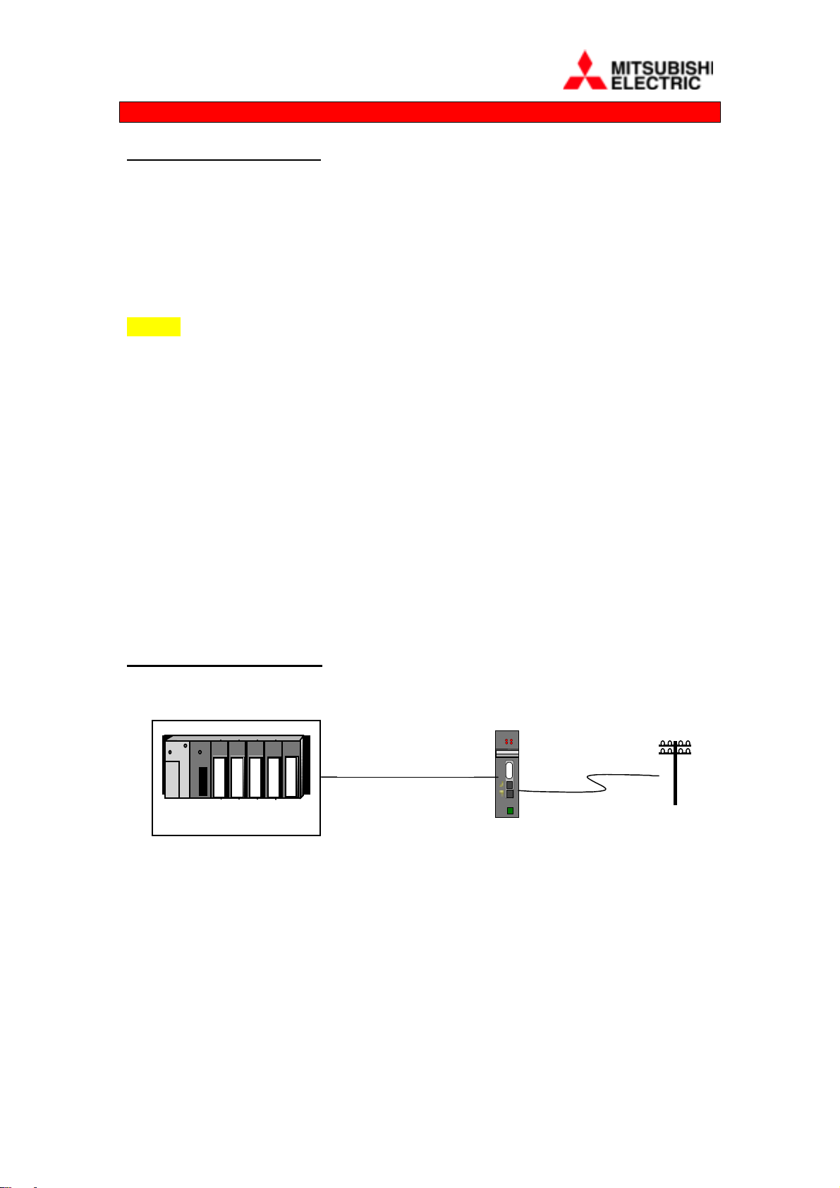
2.2.1 Connection to a Link module (eg. A1SJ71C24-R2)
Modem-A2S
RD
CD
MODEM-R2-
AnS/QnS/A via C24 (R2)
DATA
RS232
VOICE
LINE
24V
OV
i) Connect the 9-pin to 9-pin cable type (MODEM-R2-CAB), between the
Data RS232 port on the front of the DIN-MODEM-2 or A2S-MODEM and
to the RS232 connector on the front of the A1SJ71C24-R2 link module.
ii) Connect the telephone lead provided by plugging in the RJ11 type plug into
the socket labelled LINE, making sure that the connector is properly latched.
iii) When simultaneous voice and data is required, connect a suitable handset or
headset by plugging into the socket labelled VOICE.
iv) Connect a 24V or 12V dc supply via the connector provided. The dc
polarity is not important as it is corrected within the MODEM.
3
continued
S
T
O
2.2.1
NOTE 1: Modems cannot be connected directly to the CPU programming port.
NOTE 2: Set the Link module to protocol 1, Write during run, 9600 baud, 8 data bits,
No parity, 1 Stop bit and Sum Check ON. Eg. MODE=1, SW04,05,07,08 &12 = ON,
all other switches OFF. After changing these switches turn the power to the PLC off
MITSUBISHI
MODEM-FX2-CAB
FX1S/FX1N/FX2N
+ 232-BD
MODEM-PC9-CAB
and back on alternatively reset the CPU.
2.2.2 Connection to FX2N-232-BD
i) Connect a 9-pin male to 9-pin female cable, type MODEM-FX2-CAB or
MODEM-PC9-CAB, wired to the schematic shown in Section 7, between
the Data RS232 port on the front of the MODEM and the serial port at the
top of the FX2N-232-BD plug-in module.
ii) Then follow the instructions in Section 2.2.1 ii) to iv) above
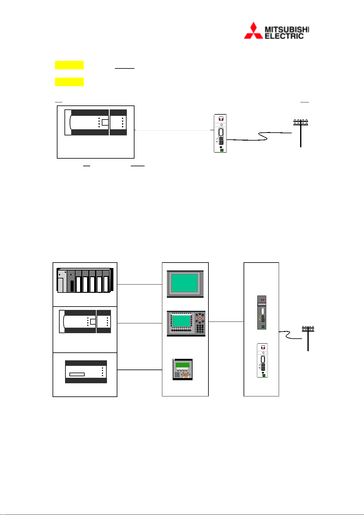
2.2.3 Connection to MAC 50/90 and E range of HMI’s
MAC 40+ CAB
Modem-A2S
RD
CD
OR
AnS/QnS/A
MITSUBISHI
MODEMMAC-CAB
FX-20P-CAB
CS
DATA
RS232
VOICE
LINE
24V
OV
FX0S/FX1S
FX0N/FX1N/FX2N
MAC 40+ CAB
MITSUBISHI
FX
iii) Connect a 9-pin male to 9-pin female cable, type MODEM-MAC-CAB,
wired to the schematic shown in Section 7, between the Data RS232 port on
the front of the MODEM and PRINTER serial port at the back of the MAC
or E range terminal.
iv) Then follow the instructions in Section 2.2.1 ii) to iv) above
4
2.2.4 Connection to FX-232AW / FX0N-232ADP
MITSUBISHI
MODEM-R2A-CAB
FX1S/FX1N/FX2N
+ FX2N-CNV-BD +
FX0N-232-ADP
MITSUBISHI
FX + FX-232AW
i)
Connect the 9-pin to 25-pin cable, type MODEM-R2A-CAB, between the
Data RS232 port on the front of the MODEM and the RS232C Connector
on the FX232AW / FX0N-232ADP module.
ii)
Then follow the instructions in Section 2.2.1 ii) to iv) above
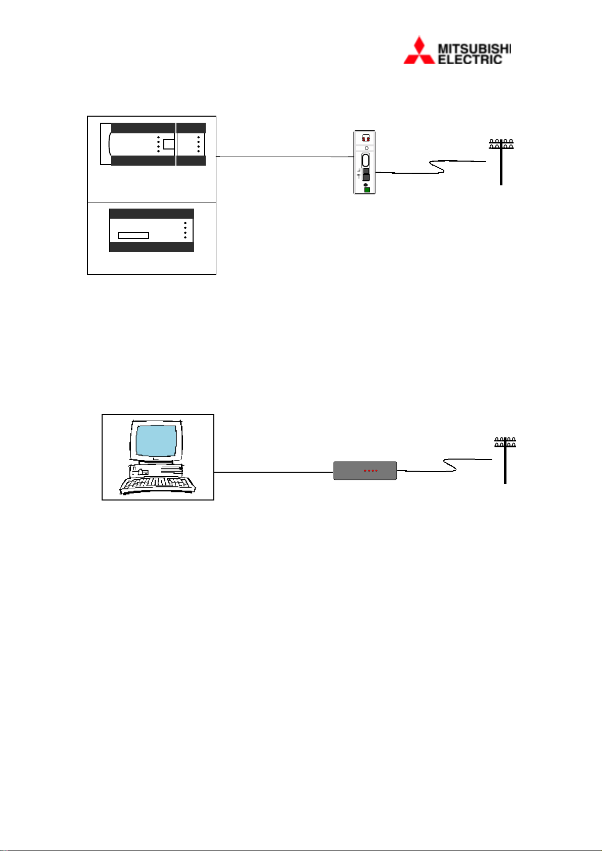
2.2.5 Connection to DESK Version
MODEM-PC9-CAB
i)
Connect the PC to Modem Data cable, type MODEM-PC9-CAB, between
the Data RS232 port at the rear of the MODEM and a spare
communication port on your PC.
ii)
Then follow the instructions in Section 2.2.1 ii) to iv) above.
logilink
336
RDSDCDTRCSOH
5

2.2.6 Wiring 24V dc Supply A2S and DIN Versions
i)
ii)
12V dc Supply DESK Version
i)
2.3 Initial configuration
Wire 24 dc from a suitable supply, usually from terminals on a nearby
module to the miniature screw terminal plug provided.
Check the specification for the 24V supply before making connection.
However, reversing the polarity of the dc will cause no harm.
Plug the 12V dc power supply provided into a mains supply and connect
the jack plug into the connector at the rear of the MODEM.
i)
ii)
Set the Modem to the correct local protocol (see 5.9 for a list of codes),
with the command:
AT%ADP=x (where x = protocol setting)
Read section 3.1 for more details.
6

Section 3 – Using the Enhanced Functions
In order to configure your modem and use its enhanced functions it must be connected
to the serial port of a PC running terminal software such as Terminal, HMI Tools
\Modem, Hyper-Terminal or ProComm Plus. This section describes how this is done.
3.1 Setting the Modem with Terminal Software The modem is pre-set to communicate at 9600 Baud with 8 data bits, 1 stop bit and
No parity. Flow control or Hardware Handshake is OFF. The terminal software must
therefore be set to match these parameters in order to communicate at all.
eg. 9600,8,N,1
3.1.1 Connecting the Modem to a PC
To connect the modem to a PC, use a suitable RS232 modem cable (accessory
MODEM-PC9-CAB), wiring for such a cable is shown in section 7.2.3.
When the modem is connected, any characters typed at the terminal software will be
echoed back by the modem.
When the modem is communicating with PC terminal software it can be configured
using AT commands, so called because they are all preceded with the letters AT. A
full list of these commands is given in section 5. The modem is supplied with all
essential parameters for plug and pla y already set, but if t hese are lost for any reason
the device can be reprogrammed with the following command string:
AT&F&D0S0=1 &W0 (all 0’s are zeros)
or
AT%F (version 1.20 or later)
3.1.2 Configuring the Modem
Before the modem can be connected to a PC/Laptop, PLC or an HMI it will be
necessary to set the modem to the correct protocol. Just as the HMI, for example,
requires to know what PLC it is connected to, the modem has special protocol settings
for different configurations. Refer to
the following command string,
AT%ADP=x (x = protocol setting)
Example 3-1 Protocol settings
AT%ADP=0 (or 1) Modem connected to a PC/Laptop (default)*
AT%ADP=3 Modem connected to an FX PLC
AT%ADP=A Modem connected to an AnS PLC via an E HMI
section 5.9 for a list of protocol settings and use
* Earlier versions before 1.20 were set to protocol 1.
7

3.2 Automatic Simultaneous Voice and Data
To use the ASVD function, simply plug a suitable handset or headset into the front
panel socket marked with a handset symbol. Voice and data communication will be
made automatically during the period that the modem is connected.
3.2.1 Using Simultaneous Voice and Data with Other Modems
Not all modems available support simultaneous voice and data functions. First ensure
that the other modem is capable of supporting this feature. Refer to the other
modem’s handbook to see if it supports analogue or Audio Span voice and data.
NOTE:
It is highly recommended that the ASVD feature be always used when any on-line
changes are made to the PLC code. A risk of damage to equipment connected to the
PLC or even injury may occur if alterations are made to the program or data without
continuous voice contact with a local operator.
8
3.3 Online Maintenance Using Mitsubishi PLC Programming Software
24
LINE
One of the most commonly used features of th e modem is to contact a remote PLC
and then use programming software to interrogate operation. To do this requires a
two-stage operation.
Modem-A2S
RD
CD
CS
DATA
RS232
logilink
336
RDSDCDTRCSOH
VOICE
OV
MITSUBI
SHI
FX0S/FX1S
FX0N/FX2N
MITSUBI
SHI
FX
3.3.1 Making a Connection
Firstly, with the modem connected to your PC running terminal software, dial the
remote modem. Entering the command ATD followed by the telephone number of
the remote site is one way of doing this.
NOTE: Ensure the settings in the terminal software have been set to 9600,8,N,1.
Example 3-2 Dialling
ATD 0123456789 <enter> to dial a site on 0123456789
ATDT 0123456789 <enter> forces tone dialling (default)
ATDP 0123456789 <enter> forces pulse dialling
Secondly, close the terminal application (do not minimise). The modem will hold the
connection. Then run your Mitsubishi programming software from Windows, for
example, GPPWIN.
3.3.2 Terminating a Call
To terminate the connection, exit the programming software and r estart the terminal
application. Then select “Hang-up” or type:
+++ (3 pluses) followed by a pause of at least 1 second, or until the modem returns
“OK”
Then type ATH <enter> to ‘hang up’, the modem will close the connection and go onhook.
If the modem does not respond with OK after the three + symbols, try again.
9

3.3.3 Communicating with Mitsubishi PLC’s
Using the A2S/DIN/DESK Modems you will be able to transfer data between a
PC/Laptop and a PLC, seamlessly without making any changes to the default settings
in the HMI or Programming software. The modem can be connected directly to the
PLC via a suitable RS-232 interface or through an HMI port in the “Transparent”
mode, refer to section 2.
A simple test would be that if you are able to programme or monitor the PLC or HMI
when directly connected using the appropriate cable, then the same settings will apply
for the A2S Modems. The intelligence within the modem automatically adjusts
formats, even speeds to suit the individual PLC and HMI configuration. These unique
features, for example, include the ability to recognise when the software is addressing
the HMI and allow “high speed” data transfers.
3.3.4 Communicating with E series and MAC HMI’s
There are two methods of communication between the HMI and PC using Modems.
a) Method 1 (preferred):
Using two Mitsubishi A2S/DIN/DESK MODEMs at both ends.
This unique method provides the following features:
• transfer rates of up to 38400 baud.
• uses default software settings
• allows switching between HMI and PLC without having to redial.
NOTE:
1) Prior to installation, each modem must be set to a protocol matching the local
device with the protocol command, for example, AT%ADP=F for FX series and A
for A/Q series via HMI, refer to section 3.1.
2) If “HMI File transfers” (see section 3.3.5) are also required, when the HMI is
connected to an FX series PLC,
9600,8,N,1. This can be altered via the HMI software in “Set-up/Peripherals” or
via the HMI Front Panel.
Firstly, make connection in the normal way, (see 3.3.1, above), then close the
Terminal application (do not minimise).
Secondly, load the HMI programming software and select the speed “settings” to a
baud rate up to 38400 then, with the “Automatic terminal RUN/PROG” selected,
Transfer your Project in the normal way.
After each successful transfer the modems will automatically return to 9600 baud to
allow normal transparent mode to take place.
the RS232 port in the HMI must be changed to
b) Method 2:
Dialling from another manufacturers make of modems connected at the PC end.
Firstly, select 2400 baud in the terminal software before making a connection then
close the Terminal application (do not minimise).
10

Secondly, load the HMI programming software and adjust the speed ‘Settings’ to
2400 baud in the ‘Transfer \ Project’ window before starting the transfer.
NOTE: After each successful transfer the call must be terminated and redialled at
9600 baud before normal transparent mode to the PLC can be resumed.
CAUTIONARY NOTE:
At the time of writing. it is only possible to communicate with the E range and certain
versions of the MAC range of HMI’s, using either method 1 or 2.
3.3.5 Transferring files from/to the HMI
It is also possible to download files held in the E HMI, for example, “Trends”,
“Recipes” and “Alarm Lists”. To do this requires the HMI to be dialled from the
Windows HMI Tools program “Filetran”.
Firstly, enter your telephone numbers in the Connections list by selecting ‘Edit’,
under ‘Options\Comm Settings’. Then check that the communication is set to
9600,8,N,1.
a) Method 1 (preferred):
Using two Mitsubishi A2S/DIN/DESK MODEMs at both ends.
To dial your chosen telephone number click ‘Connect’ and wait for the Files to be
displayed before selecting the files to receive or send..
To “Hang-up”, click on the ‘Close’ button and the modems will return to their normal
“command mode” state.
b) Method 2:
Dialling from another manufacturers make of modems connected at the PC end.
Firstly, make sure that the RS232 port in the HMI is set to 9600,8,N,1 then dial as
described in
NOTE:
The RS232 port in the HMI will need to be changed back to the FX or AnS format
every time it is required to program a PLC through the transparent mode.
3.3.6 Communicating with other makes of PLC controllers
Because the purpose of the Modems’ on-board intelligence is to communicate
specifically with the Mitsubishi range of PLC’s there may be some difficulty in
transferring data between other makes. Until a local protocol has been written for the
device being connected, setting another code will confuse the modem and it will
incorrectly convert the serial format.
method 1
, above.
To allow the A2S type modem to be used for non-Mitsubishi equipment, for example
On-line Maintenance operation, it will be necessary to set the remote A2S Modem
into the special transparent protocol, as follows:
11

AT%ADP=T,<Baud rate,No. Data bits,Parity,No. Stop bits><enter>
Example 3-3 Transparent settings
AT%ADP=T,9600,7,E,1
AT%ADP=T,19200,8,O,2
You can check your setting by typing:
AT%ADP?<enter>
Example response,
Transparent – 19200,8,O,2
The local Modem must also be set to the Baud rate and format to match the remote
Modem. Depending on the type of modems there are two different wa ys of achieving
this, as follows.
1) For the A2S MODEM set the transparent m ode, as above, then after connecting
quit the Terminal software and load and run the equipment software to transfer data.
Before you can “hang-up” the A2S Modem, the Terminal software must be set to the
adjusted baud rate and format.
NOTE: The Terminal must be returned to the default setting of 9600,8,N.1 before
redialling, each time.
2) For another make of modem set the Terminal software to the new format
matching the “Transparent” settings, then type AT<enter> to set the modem. The
modem should respond with “OK” to indicate synchronisation.
Then Dial or Hang-up the remote modem in the normal way, whilst retaining the new
settings.
12

3.4 Security
Your modem has the powerful facility of a two level access code (password) facility
we call “User” and “Administrator” levels. The codes will both protect your system
from unauthorised connection/communication and allow the on-line configuration of
the remote modem’s parameters. Once set, anyone dialling in must enter the correct
User access code before data will be allowed to pass through to your system. The
modem will disconnect the line after the third ‘wrong code’.
3.4.1 Normal Operation
1) User Access Code Installed
!
Dial the modem in the normal way from a PC and after connection has
been established the modem will make the request ‘ENTER
PASSWORD’.
!
Enter your access code (up to 8 characters, UPPER CASE ONLY) plus
a carriage return <enter>.
!
If the correct code has been entered the modem will establish full
connection, providing an open line to your system. If an incorrect code
has been entered the modem will repeat the ‘ENTER PASSWORD’
prompt for a total of three attempts.
!
Failure to enter the correct code on the third attempt will cause the
modem to hang up and the ‘NO CARRIER’ message will be displayed.
2) User Access Code Disabled (default)
!
No request for a code will be displayed and an open data connection to
your system is made.
3) Administrator Access Code
!
Dial the modem in the normal way from a PC Terminal application and
wait for the usual ‘CONNECTED’ prompt to be returned.
!
If the User Access Code had been previously enabled you will be
prompted with ‘ENTER PASSWORD’, as normal. Do not enter the
“User” code.
!
Enter the Administrator code (up to eight characters, UPPER CASE
ONLY) followed by <enter>. The default code is ADMIN.
!
If the correct code has been entered, “OK” will be returned and you
will then be allowed to access the specialised modem settings of the
remote modem. This is referred to as the “Online Configuration”
mode, (see section 3.5.2).
!
You only have one chance to type the correct code, unless you h ave the
“User” code enabled, then there will be three chances.
!
When you have completed any changes, t ype *** (three stars ) and wait
until the remote modem responds with “OK”. The modem will then
effect any changes made and establish an open line to your system.
NOTE: To be able to use the password facility the user should use a terminal
application, such as the Terminal programme, provided. Using software with built-in
Modem support may not provide password facility.
13

3.4.2 Installing the Access Codes
To install or change an access code it will be necessary to connect a PC directly to the
modem via the PC serial port and the RS232 data connector. Use the MODEM-PC9CAB or suitable lead and run your terminal software.
1) Installing for the first time
!
The factory default setting is no user code set.
!
To install your user code for the first time use the following command:
AT%ACU = *,<new code> [Enter]
!
(Where the new code can be one to eight characters long)
2) Changing the user code
!
To change the user code you will require either the current user or
administrator codes and use the following command:
AT%ACU = <current code>,<new code> [Enter]
!
The modem will respond with
OK (when accepted) or
ERROR (when current code is incorrect)
!
Current code may be either the user or administrator codes.
3) Disabling the user code
!
To disable the user code enter * in the new code field and the current code in
the following command:
AT%ACU = <current code>,* [Enter]
!
The modem will respond with
OK (when accepted) or
ERROR (when current password is incorrect)
!
Current code may be either the user or administrator codes.
4) Changing the administrator code
!
To change the administrator code you will need to know the current
administrator code (default = ADMIN) and use the following command:
AT%ACA = <current admin code>,<new admin code > [Enter]
!
The modem will respond with
OK (when accepted) or
ERROR (when current admin code is incorrect)
!
Current admin code must be the administrator code.
NOTE: The codes are not case sensitive as all codes are converted to upper case.
Also, the administrator code cannot be disabled.
5) In case of problems
In the unfortunate event that the password has been lost or the modem has been
sabotaged, contact your supplier for assistance. It may be possible to return the
password back to the original factory setting.
14

3.5 Dial On Demand
The dial on demand facility enables an FX or AnS PLC to command the modem to
dial pre-stored telephone numbers and automatically exchange data with a remote site.
IMPORTANT NOTE:
The facilities described in sections 3.5 and 3.6 will not operate from an An(S)/QAn(S)
PLC when connected via an HMI.
The pre-stored telephone numbers may be either speed dial numbers (stored in the
modem) or located within PLC registers. How to set up the telephone numbers is
explained in section 3.5.5.
The data exchanged may be to either send fixed text messages stored within the
modem or to read/write blocks of data from within the PLC. The process of setting up
fixed text messages is explained in section 3.5.6, while data transfers are dealt with in
section 3.6. Alternatively the modem can be commanded to stay on line either to
repeat the data transaction, or wait on line until instructed to hang up by either end.
Dial on demand operates by configuring the modem to poll a block of PLC
(command) registers, which provide the modem with instructions, explained in
section 3.5.3.
NOTE: Throughout this section the Local system is the one making the call, while the
Remote system is the one being called.
3.5.1 Setting Dial on Demand Commands
To set up Dial On Demand it will be necessary to connect a PC directly to the modem
via the PC serial port and the RS232 data connector. Use the MODEM-PC9-CAB or
suitable lead and run your terminal software.
1) Defining the local PLC type
Because different PLC’s use different communications protocols it is necessary to set
the modem to the type of PLC that it is connected. This is done by entering a protocol
code with the command:
AT%ADP = x
Where x =0 No protocol/Desk (factory default version 1.20 or later)
All other protocols are listed in section 5.9.
15

2) Locating the command registers
The command registers may be located in any valid D-type register within the PLC. A
contiguous block of 7 registers is required. The modem will need to know the start
address of this block and this is done with the command:
AT%ADR = xxxxxx
Where xxxxxx is the address from 1 to 6 digits.
Example 3-4 Command Block Address setting
AT%ADR = 1000 Defines the command block at D1000
AT%ADR = 20 Defines a command block at D20
Also, the command block need not be within the same PLC connected to the modem.
It may be in another PLC connected over a local network. The PLC network number
may be defined using the command:
AT%ADN = FF FF is the default setting.
3) Starting the poll
Polling is started by the command:
AT%ADO = 1
And stopped by the command:
AT%ADO = 0
Polling will start approximately 10 seconds after the next modem reset.
If the modem does not receive a response to its poll request, polling will be
temporarily suspended until the next reset.
If the modem is still connected to a PC terminal when it starts to poll, then you should
see a formatted read request strin g appear. If you are able to interpret such strings,
this can be used as a useful tool to check your settings are correct.
3.5.2 Online Configuration
Any of the parameters listed in the whole of section 3 may be modified in a remote
modem by calling it and entering the Administrator Access Code. For a full
explanation of how to do this see
section 3.4.1 3).
16

3.5.3 Contents of the command block
The contents of the command block within the PLC are shown in the following
figures.
For a sample program that uses the dial on demand facility see section 10 at the end of
this manual.
COMMAND BLOCK
MSB LSB
D(x) E
R
R
D(x+1) Tel. No.#1 Tel. No. #2 Tel. No. #3 Tel. No. #4 Telephone Number
S
Y
N
N
R
S
Error code
PLC
Comms
N
A
N
N
D
T
N
C
D
B
S
Y
TCPFS
RQStatus register
T
P
register
D(x+2) Message#1Message
#2
D(x+3) [D]0~1999 Directory A Telephone
D(x+4) [D]0~1999 Directory B Telephone
D(x+5) [D]0~1999 Directory C Telephone
D(x+6) [D]0~1999 Directory D Telephone
Where
D(x) = Head address of the Control Block as specified by the AT%ADR command.
3.5.4 Control and Status Register
The first resister of the command block read back from the PLC is dealt with on a bit
by bit basis, the break down of which is detailed below.
Message
#3
Message#4Message register
No. head address
No. head address
No. head address
No. head address
D(x)
Erro r Flag
Sy ntax Error b13
N o R espo nse b 12
PLC co mms er ro r co d e b 1 1 -8
b0 D ial Request
b1 Stopped Polling
b2 P o llin g Flag
b3 Tran s miss io n Comple te
b4 L ine Busy
b5 No C arrie r
b6 N o D ial Tone
b7 No Answer
17

1) Dial Request Bit (bit 0)
In order to trigger a dial on demand action, the PLC program needs only to set
the Dial Request (RQ) bit in the first register of the command block. When
the RQ bit is set the telephone and action data is retrieved by the modem in the
same poll, so remember to set these values before the bit!
2) Stopped Polling bit (bit 1)
The Stopped Polling bit (STP) is set by the modem while it is performing a
dial out operation. It may be used in conjunction with the poll flag below to
indicate that polling has been temporarily suspended.
3) Polling Flag bit (bit 2)
The poll bit is toggled by the modem after every successful poll has been
made. This feature may be used by the PLC (particularly one at a remote site)
to determine if the modem has stopped polling it for some reason.
CAUTIONARY NOTE:
The polling bit is set and reset by a word write command. The remaining bits
in the register are overwritten with the data they contained at the time of the
poll read request. Therefore, take care when setting the RQ bit; perhaps by
triggering on the rising/falling edge of the poll bit.
4) Transmission Complete bit (bit 3)
The Transmission Complete bit (TC) is set by the modem when it has; made a
successful dial out, connected, and has performed all the transactions indicated
in the message registers. Used by the PLC as an indicator that the modem has
dealt with the request, and may be used to trigger a new set of transactions.
5) Error bits (bits 15-7)
The first address of the command block has a number of bits allocated for
error reporting by the modem. These bits are set by the modem in the event of
an error and presented to the PLC on an information only basis.
Bit 15 – General error – set when any error occurs
Bit 13 – Syntax error – set when either the local or remote PLC responds with
three consecutive NAK messages.
Bit 12 – No response – set when the remote PLC has not responded in three
seconds to a WAT request, in three consecutive attempts.
Bits 11 to 8 – PLC communication error – accompanies the syntax error flag,
the least two significant characters returned by a NAK response are copied
here. (AnS PLC only).
Bits 4 to 7 – dial errors – these flags are set when a dial attempt has failed for
one of the following reasons: Line busy, no carrier, no dial tone, or no answer.
18

3.5.5 Setting telephone numbers
When dial on demand is required, the modem uses the first telephone number v alue
from the command block to determine the number to dial. If this value is in the range
of 1 to 9 a speed-dial number is selected. If the value is in the range A to D (hex) then
the modem will read a block of registers from the PLC, then dial the returned value.
b15 b0
D(x+1) Tel. No.#1 Tel. No. #2 Tel. No. #3 Tel. No. #4 Telephone No. address
Where (x+1) = Command Block address +1
1-9h for Speed Dial addresses
A-Dh for Directory addresses
0h for NO telephone number
Telephone addresses are stored in HEX and must include all 4 numbers, e.g. 2300 not
23, [call telephone number in speed-dial address 2, then 3 if 2 is busy, etc.]
1) Setting speed-dial numbers in the modem
These numbers are stored within the modem, so must be pre-set by connecting
the modem to a PC terminal, and using the command:
AT&Zn = <telephone number>
Where n is the speed-dial address in the range of 1 to 9
<telephone number> may be 15 characters long
Example 3-5 Setting Speed-Dial numbers
AT&Z3=01234567890 [Tel. No. 01234 567890 set at address 3]
When a value of 1 to 9 is found in the data returned from the PLC the
corresponding number is looked up then dialled.
2) Setting directory numbers in the PLC
The start addresses of the four possible PLC locations (A-D) are included in
the command block and returned with each poll request. A block of five
registers is read from the start address indicated in the command block. Each
register holds up to four (hex) digits of the phone number, therefore the
number can be twenty digits long.
Entering a value of F (hex) indicates the end of the telephone number.
Example 3-6 Directory Dialling (PLC programming)
Command Block address D1000 and Directory Telephone No. in D405-409.
MOVP D405 D1003
Set Directory A header address
MOVP HA000 D1001
MOVP K1 D1000
19
Set Telephone address A
Set Dial Request bit 0=1

By either swapping the value of the address in the command block, or by
swapping the value at the directory address before making a dial request; a
huge directory of telephone numbers becomes available, limited only by the
amount of free data registers within the PLC.
3.5.6 Setting fixed messages in the modem
Fixed (text) messages are stored within the modem, so must be pre-set by connecting
the modem to a PC terminal, and using the command:
AT%MSGn = <message>
Where n = the message address in the range 1 to 9
<message> may be up to 48 characters long.
Example
: AT%MSG2=Pumping Station No. 2 [stores message in address2]
b15 b0
D(x+2) Msg. #1 Msg. #2 Msg. #3 Msg. #4 Message register
Where (x+2) = Command Block address +2
1-9h for Fixed Message addresses
A-Dh for WAT Messages/Data addresses (see section 3.6 for more information)
Eh for On-Line polling
Fh for Stay On-Line
0h for end of messages, hang up
Message addresses are stored in HEX and must include all 4 numbers, e.g. 12F0 not
12F. [send 2 messages from addresses 1 and 2, then Stay On-Line (F)]
When a value of 1 to 9 is found in the returned data, the corresponding message is
looked up then sent to the remote site.
The modem will automatically hang up when a value of 0 (zero) is found or after all
four messages have been actioned.
When the hexadecimal value E is found; the modem stops processing messages, sets
the Transmission Complete bit in the PLC command register, then resumes polling.
However, the modem does not hang-up, terminating the call. This feature is useful
when more than four transactions are required, and is particularl y useful when doing
Wide Area Telemetry.
When the hexadecimal value F is found; the modem stops processin g messages, sets
the transmission complete flag, but does not resume polling. Again the modem does
not hang-up, terminating the call. This feature is useful when an error has occurred
that requires operator intervention from a remote site.
Example 3-7 Setting Messages from the PLC
MOVP H12F0 D1002
Set Fixed messages 1,2 and
Stay on-line.
MOVP HABE0 D1002
Set WAT A,B then On-line
monitoring.
20

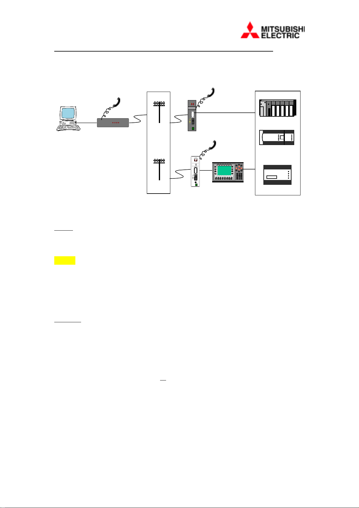
3.6 Wide Area Telemetry (WAT)
One of the most exciting features of your modem is its ability is not just to
automatically dial on demand, but also exchange information with another, remote
PLC. We refer to this process as Wide Area Telemetry (WAT) as it gives you the
possibility of setting up a wide area network of PLC’s.
AnS, A
MITSUBIS
MITSUBIS
MITSUBIS
MITSUBIS
FX0S/FX1S
FX0N/FX2N
FX
Modem-A2S
RD SD
CD TR
CS OH
DATA
RS232
VOICE
LINE
24V
OV
Modem-A2S
RD SD
CD TR
CS OH
DATA
RS232
VOICE
LINE
24V
OV
AnS, A
MITSUBIS
MITSUBIS
MITSUBIS
MITSUBIS
FX0S/FX1S
FX0N/FX2N
FX
In the previous section (3.5) it was mentioned that placing the values A to D (hex)
into one of the message slots of the command block would enable a WAT transaction.
3.6.1 Setting the Start Address of WAT Information
The information used to perform a WAT operation is stored in a WAT header; any
contiguous block of three D type registers within the PLC may be used. All the
modem needs to know is the first address.
To program the start address in the modem, use a PC terminal to communicate with it
and type an AT command in the following format:
AT%WATn = 1234
Where n is the letter A to D and corresponds to the hexadecimal value set in the
message register of the control block above.
1234 is an example start address
Example 3-8 Setting WAT addresses
AT%WATA = 500 when hexadecimal A is found in the message register
the modem will read address D500 for instructions.
AT%WATD = 22 when hexadecimal D is found in the message register
the modem will read address D22 for instructions.
21

3.6.2 Information in the WAT Header
The instructions read by the modem from t he WAT header are in the form shown in
the two figures below. It is the responsibility of the PLC program to transfer the
correct information into these registers before requesting the transaction.
WAT REGISTERS
MSB LSB
D(y) Number of data words to
transfer (hex value)
Read/Write
Remote
Remote
Protocol
Header #1
D(y+1) Remote Register/Device Prefix
Header #2
(One ASCII Number or letter)
D(y+2) Remote Head Address
Header #3
(0-1999 decimal)
D(y+3) 1st Data Word Data #1
D(y+4) 2nd Data Word Data #2
D(y+x) (x) Data Word
Data #x
(where x = 16 (10 hex) maximum)
Where D(y) = Head Address of the WAT Message data area specified with the
AT%WAT command.
The contents of Header #1 are further described below.
b15
D(y)
b0
WAT Header Address#1
b0-3 Remote Protocol No.
b 4-7 Remote Read/Wri te bit
b8-15 Number of words
Where D(y) Is the first WAT header address.
Bits 15 to 8 - The number of words to Transmit or Receive are limited to 16 (1 to 10h)
Bits 7 to 4 - Read/Write Remote, 0 = Read from Remote and 1 = Write to Remote.
Bits 3 to 0 - Remote Protocol Number refers to the remote PLC type, e.g. 1 = AnS PLC,
3 = FX PLC.
22

Detail of WAT header address’ #2 & 3.
b15b
)
b
b
0
WAT Head er A ddr ess # 2D(y+1)
b0-7 D evi ce pr efix l etter
Bits 7 to 0 – The Device Prefix letter in ASCII Hexadecimal, eg. X,Y,M,B,D,W, etc.
15
D(y+2)
0
WAT Hea d er A ddr ess # 3
b0-15 Device Address
Bits 15 to 0 – Device address in Decimal, Hexadecimal or Octal, eg. 1000, 3F, etc.
Example 3-9 WAT settings in the PLC (Write Remote command)
WAT Header address = D200, Writing 1 word to outputs Y0 to Y17 on an FX PLC.
MOV H0113 D0200
ASC Y D0201
MOV K0 D0202
MOV H5555 D0203
Set 1word,Write, FX protocol
Set Device = Y
Set Device address = 0
Set Data (Y0 and all even numbers to
Y26 will be switched ON, odd
numbers OFF
Example 3-10 WAT settings in the PLC (Read Remote command)
WAT Header address = D300, Read 16 (10h) words from D500 in an AnS PLC.
MOV H1001 D0300
ASC D D0301
MOV K500 D0302
BMOV K0 D0303 K16
Set 10h words, Read, AnS protocol
Set Device = D
Set Device address = 500
Clear 16 registers from D303 (not
obligatory). Data from D500 to 515 in
the remote AnS PLC will be read
directly into registers D303 to 318.
23

3.7 WAT Settings and Procedures before operation
Start
1.Reserve 7 (D) registers for the Command Block
(see 3.5.3)
2.Reserve 3 (D) registers for the WAT header +
16 registers for the WAT data (see 3.6.2)
Set-up the A2S Modem using the
following commands:
AT%ADP=<PLC type>
AT%ADR=<command block Addr.>
AT%WATA to D
AT%ADO=1
Yes No
Speed Dial
Set telephone numbers in the Set-up a Directory in the
A2S Modem with command PLC (5 registers per teleAT&Z1 to 9 (see 3.5.5 1)) phone No. (see 3.5.5 2))
Programme the PLC to transfer the WAT
strategy, eg. Read or Write, No. words and
the remote PLC Type (see Examples 3-9 & 10).
Set the Message register for the order in which
the WAT addresses are to be transmitted
(see Example 3-7)
Set the Telephone register
Set the “Dial Request” bit to start operation.
End
24

Section 4 – Troubleshooting
Your modem is designed to provide reliable and trouble free functionality. However,
should you experience any difficulty, the information in this section may assist you in
determining and resolving the source of the problem. If you cannot resolve your
situation after reading this chapter, contact your dealer of the Technical Support
Centre at the number provided on the last page of this manual.
4.1 The modem does not respond to commands
1. Ensure that the PC is not configured to a conflicting COM port and/or IRQ
setting. Your modem cannot be connected to a COM port currently in use by
another device in your system (e.g. mouse). Similarly IRQ settings must not
overlap.
2. Make sure that the communication software is configured with the correct COM
and IRQ settings (i.e. the same as the modem). Your communication software
will not be able to send or receive data if it is not configured to match the COM
settings of the modem
3. Check that the modem is not configured to echo off or command reporting off.
This can be done by typing the commands ATE1 to restore echo and ATQ0 to
restore command reporting. By default, the modem will be set to echo off and
reporting off.
4. The modem will not respond to commands if Dial On Demand is enabl ed, for the
first ten seconds after power up.
4.2 The Modem Dials but Does Not Connect
1. The best method of diagnosing this kind of problem is always to connect a
suitable head or handset to the modem as it is dialling.
2. Check that you are dialling the right number.
3. Check that the remote modem has the correct line cable connected.
4. If the remote site keeps ringing without picking up, it may either be unplugged or
it has not been programmed to auto-answer. Setting the modem with the
command ATS0=1 instructs auto answer after 1 ring.
5. Check that the line connected to the remote modem is not part of a digital miniexchange, this type of system requires an analogue (2-wire) adapter.
4.3 The Modem Does Not Dial, Reporting “NO DIALTONE”
Problems of this type are almost always due to the telephone cable/connection.
1. Check that the telephone cable is connected correctly to the modem and phone
socket.
2. Check that the cable used is the correct type for the country you are in, the one
supplied is only suitable for connection in the UK. Line connections are delivered
on pins 3 & 4 of the line socket.
25

4.4 The Modem Stops Polling After First Poll
1. Only applies to Dial On Demand polling
2. Check that the serial cable that you are using to connect to the PLC is right for the
PLC.
3. If using a communications module, check that its settings are correct
4. If connected to an HMI terminal, check that its communications settings are
correct
4.5 Polling Occurs, but will not Dial On Demand
1. Check that the register address polled is correct, AT%ADR setting.
2. Check that the PLC program is setting the RQ bit.
3. Check that there is at least one value in the telephone register of the command
block, and that it the value has sufficient trailing 0’s, i.e. 1000 not 1.
4. If using speed-dial numbers, check that the number requested is set in the modem,
At&Zn setting.
4.6 Modem occasionally hangs-up during WAT data exchange.
This is usually caused by an unacceptable number of data errors, detected during a
WAT operation.
1. Check cable connections.
2. The problem may be caused by poor Telephone Network connections, for
example, Exchange faults or old lines.
3. Try reducing the Baud rate between the A2s Modems on the Network by
changing the AT%NET setting from the default 28800 rate.
4.7 Occasional “Re-tries” occur during Programming/Monitoring.
This is probably due to poor Telephone Network connections.
1. Try another Line or redial.
2. If you are dialling from a Mitsubishi A2S/DESK Modem try reducing the Baud
rate, using the AT%NET command.
26

Section 5 – AT Command Set and S - Registers
All commands below are preceded with AT. The commands are not case sensitive.
5.1 Standard Commands
Command Function
A/ Re-execute command
A Go off-hook and attempt to answer an incoming call
B0 Select V.22 connection at 1200bps
B1 Select Bell 212A connection at 1200bps
C1 Return OK Message
Dn Dial modified by parameter n
E0 Turn off command echo to terminal
E1 Turn on command echo to terminal
F0 Select auto-detect mode (equivalent to N1)
F1 Select V.21 or Bell 103 line modulation
F2 Reserved
F3 Select V.23 line modulation
F4 Select V.22 or Bell 212A 1200bps line modulation / speed
F5 Select V.22bis line modulation
F6 Select V.32bis or V32 4800bps line modulation / speed
F7 Select V.32bis 7200bps line modulation / speed
F8 Select V.32bis or V.32 9600bps line modulation / speed
F9 Select V.32bis 12000bps line modulation / speed
F10 Select V.32bis 14400bps line modulation / speed
H0 Initiate hang-up sequence
H1 If on-hook go off-hook and enter command mode
I0 Report product code
I1 Report pre-computed checksum
I2 Report OK
I3 Report firmware revision and interface type
I4 Report response programmed by an OEM
I5 Report the country code parameter
I6 Report modem data pump model and code revision
I7 Reports the DAA code
L0 Set low speaker volume
L1 Set low speaker volume
L2 Set medium speaker volume
L3 Set high spea ker volume
M0 Turn speaker volume off
M1 Turn speaker on during handshaking and turn speaker off
M2 Turn speaker on during handshaking and while receiving carrier
M3 Turn speaker off during dialling and receiving carrier and on during answering
N0 Turn off auto-mode detection
N1 Turn on auto-mode detection
O0 Go on-line
O1 Go on-line and initiate a retrain sequence
P Dial modifier, force pulse dialling
Q0 Allow result codes to DTE
Q1 Inhibit result codes to DTE
Sn Select S-Register n
=v Set the value of S-Register to value v
? Return the current value of parameter
T Dial modifier, force DTMF dialling
V0 Report short form (terse) result codes
V1 Report long form (verbose) result codes
W0 Report DTE speed in EC mode
W1 Report line speed. EC protocol and DTE speed
W2 Report DCE speed in EC mode
X0 Report basic call progress result codes i.e. OK, CONNECT, RING, NO CARRIER
(also for busy if enabled, and dial tone not detected), NO ANSWER and ERROR.
27

X1 Report basic call progress result codes and connection speeds i.e. OK, CONNECT,
RING, NO CARRIER (also, for busy, if enabled, and dial tone not detected), NO
ANSWER, CONNECT XXXX and ERROR.
X2 Report basic call progress result codes and connection speeds i.e. OK, CONNECT,
RING, NO CARRIER (also, for busy, if enabled, and dial tone not detected), NO
ANSWER, CONNECT XXXX and ERROR.
X3 Report basic call progress report codes and connection speeds i.e. OK, CONNECT,
RING, NO CARRIER, NO ANSWER, CONNECT XXXX, B USY, and ERROR.
X4 Report all call progress codes and connection speeds i.e. OK, CONNECT, RING, NO
CARRIER, NO ANSWER, CONNECT XXXX, NO DIAL TONE and ERROR.
Y0 Disable long space disconnect before on-hook
Y1 Enable long space disconnect before on-hook
Z0 Restore stored profile 0 after warm reset
Z1 Restore stored profile 1 after warm reset
&C0 Force RLSD active regardless of the carrier state
&C1 Allow RLSD to follow the carrier state
&D0 Interpret DTR on " off transition per &Qn setting:
&Q0, &Q5, &Q6 the modem ignores DTR
&Q1, &Q4 the modem hangs up
&Q2, &Q3 the modem hangs up
&D1 Interpret DTR on " off transition per &Qn setting:
&Q0, &Q1, &Q4, &Q5, &Q6 Asynchronous escap e
&Q2, &Q3 the modem hangs up
&D2 Interpret DTR on " off transition per &Qn setting:
&Q0 through &Q6 the modem hangs up
&D3 Interpret DTR on " off transition per &Qn setting:
&Q0, &Q1, &Q4, &Q5, &Q6 the modem performs soft reset
&Q2, &q3 the modem hangs up
&F0 Restore factory configuration 0
&F1 Restore factory configuration 1
&G0 Disable guard tone
&G1 Disable guard tone
&G2 Enable 1800Hz guard tone
&J0 Set S-register response only for compatibility
&J1 Set S-register response only for compatibility
&K0 Disable DTE/DCE flow control
&K3 Enable RTS/CTS, DTE/DCE flow control
&K4 Enable XON/XOFF DTE/DCE flow control
&K5 Enable transparent XON/XOFF flow control
&K6 Enab le b oth RTS/CTS and XON/XOFF flow control
&L0 Not Used
&M0 Select direct asynchronous mode
&M1 Select synchronous connect with asynchronous off line command mode*
&M2 Select synchronous connect with asynchronous off line command mode and enable
DTR dialling of directory zero*
&M3 Select synchronous connect with asynchronous off line command mode and enable
DTR to act as Talk/Data switch
&P0 Set 10pps pulse dial with 39/61 make/break ratio
&P1 Set 10pps pulse dial with 33/67 make/break ratio
&P2 Set 20pps pulse dial with 39/61 make/break ratio
&P3 Set 20pps pulse dial with 33/67 make/break ratio
&Q0 Select direct asynchronous mode
&Q1 Select synchronous connect with asynchronous off-line command mode*
&Q2 Select synchronous connect with asynchronous off-line command mode and enable
DTR dialling of directory zero*
&Q3 Select synchronous connect with asynchronous off-line command mode and enable
PTR to act as Talk/Data switch*
&Q4 Select Hayes Auto Sync mode
&Q5 Modem negotiates an error corrected link
&Q6 Select asynchronous operation in normal mode
&R0 CTS tracks RTS (asynchronous) or acts per V.25 (synchronous)
&R1 CTS is always active
28

&S0 DSR is always active
&S1 DSR acts per V.25
&T0 Terminate any test in progress
&T1 Initiate local analogue loop-back test
&T2 Returns ERROR result code
&T3 Initiate local digital loop-back test
&T4 Allow remote digital loop-back test
&T5 Disallow remote digital loop-back request
&T6 Request an RDL without self-test
&T7 Request an RDL with self-test
&T8 Initiate local analogue loop-back with self-test
&V Display current modem configurations
&W0 Store the active profile in NVRAM profile 0
&W1 Store the active profile in NVRAM profile 1
&X0 Select internal timing for transmit clock
&X1 Select external timing for the transmit clock
&X2 Select slave receive timing for the transmit clock
&Y0 Recall stored profile 0 upon power up
&Y1 Recall stored profile 1 upon power up
&Zn-x Store dial string x (to 34 chars) to location n (0-3)
%E0 Disable line quality monitor and auto-retrain
%E1 Enable line quality monitor and auto retrain
%E2 Enable line quality monitor and fall back / fall forward
%L Return received signal level
%Q Report the line signal quality
%TTn PTT certification test signals
\Kn Controls break handling during three states:
When modem receives a break from the DTE:
\K0.2.4 Enter on-line command mode, no break sent to the remote modem
\K1 Clear buffer and send break to remote modem
\K3 Send break to remote modem immediately
\K5 Send break to remote modem in sequence with transmitted data
When modem receives \B in on-line command state:
\K0.1 Clear buffer and send break to remote modem
\K2.3 Send break to remote modem immediately
\K4.5 Send break to remote modem in sequence with transmitted data
When modem receives break from the remote modem:
\K0.1 Clear data buffers and send break to DTE
\K2.3 Send break immediately to DTE
\K4.5 Send a break with received data to the DTE
\N0 Select normal speed buffered mode
\N1 Select direct mode
\N2 Select reliable link mode
\N3 Select auto reliable mode
\N4 Force LAPM mode
\N5 Force MNP mode
\V0 Connect messages are controlled by the command settings X, W, and S95
\V1 Connect messages are displayed in the single line format
+MS Select modulation
+H0 Disable RP I
+H1 Enable RPI and set DTE speed to 9600bps
+H2 Enable RPI and set DTE speed to 38400bps
+H3 Enable RPI and set DTE speed to 57600bps
+H11 Enable RPI+ mode
**0 Download to flash memory at last sensed speed
**1 Download to flash memory at 38.4kbps
**2 Download to flash memory at 57.6kbps
29

-SDR=0 Disable distinctive ring
-SDR=1 Enable distinctive ring type 1
-SDR=2 Enable distinctive ring type 2
-SDR=3 Enable distinctive ring type 1 and 2
-SDR=4 Enable distinctive ring type 3
-SDR=5 Enable distinctive ring type 1 and 3
-SDR=6 Enable distinctive ring type 2 and 3
-SDR=7 Enable distinctive ring type 1, 2 and 3
5.2 ECC Commands
%C0 Disable data compression
%C1 Enable MNP 5 data compression
%C2 Enable V.42bis data compression
%C3 Enable both V.42bis and MNP 5 data compression
\A0 Set maximum block size in MNP to 64
\A1 Set maximum block size in MNP to 128
\A2 Set maximum block size in MNP to 192
\A3 Set maximum block size in MNP to 256
\Bn Send break of n x 100ms
5.3 MNP 10 Commands
-K0 Disable MNP 10 extended services
-K1 Enable MNP 10 extended services
-K2 Enable MNP 10 extended services, detection only
-SEC=0 Disable MNP 10-EC
-SEC=1,[<tx level>] Enable MNP 10-EC and set transmit level
<tx level> 0 to 30 (0dBm to –30dBm).
5.4 W-CLASS Commands
*B Display list of permanently blacklisted numbers
*D Display list of delayed numbers
*NCn Change country code to one of eight in NVRAM
5.5 FAX Class 1
+FCLASS=n Service class
+FAE=n Data/Fax auto answer
+FRH=n Receive data with HDLC framing
+FRM=n Receive data
+FRS=n Receive silence
+FTH=n Transmit data with HDLC framing
+FTM=n Transmit data
+FTS=n Stop transmit and wait
5.6 FAX Class 2
+FAA=n Adaptive answer
+FAXERR Fax error value
+FBOR Phase C data bit order
+FBUF? Buffer size (read only)
+FCFR Indicate confirmation to receive
+FCON Facsimile connection response
+FCIG Set the polled station identification
+FCIG: Report the polled station identification
+FCR Compatibility to receive
+FCSI: Report the called station ID
+FDCC= DCE capabilities parameters
+FDCS: Report current session
+FDIS: Report remote capabilities
+FDIS= Current sessions parameters
+FDR Begin of continue phase C receive data
30

+FDT= Data transmission
+FDTC: Report the polled station capabilities
+FET: Post page message response
+FET=n Transmit page punctuation
+FHNG Call ter minatio n with status
+FK Session termination
+FLID= Local ID string
+FLPL Document for polling
+FMDL? Identify model
+FMFR? Identify manufacturer
+FPHCTO Phase C time-out
+FPOLL Indicates polling request
+FPTS Page transfer status
+FREV? Report identity revision
+FSPL Enable polling
+FTSI: Report the transmit station ID
5.7 Voice/Audio Commands
#BDR Select Baud rate (turn off au t o Baud)
#CLS Select data fax or voice
#MDL? Identify model
#MFR? Identify manufacturer
#REV? Identify revision level
#SPK= Speakerphone setting
#TL Audio output transmit level
#VBQ? Query buffer size
#VBS Bits per sample
#VBT Beep tone timer
#VCI? Identify compression method
#VGT Set playback volume in the command state
#VLS Voice line select
#VRA Ring back goes away (originat e)
#VRN Ring back never came timer (originate)
#VRX Voice receive mode
#VSK Buffer skid setting
#VSP Silence detection period (voice receive)
#VSR Sampling rate selection
#VSS Silence detection tuner (voice receive)
#VTD DTMF/tine reporting
#VTM Enable timing mark placement
#VTS Generate tone signals
#VTX Voice transmit mode
31

5.8 S-Registers
Registry No. Function
S0 Number of rings to auto answer
S1 Ring counter
S2 Escape character
S3 Carriage return character
S4 Line feed character
S5 Back Space character
S6 Wait time for dial tone before blind dialling, or after ‘W’ modifier
S7 Wait time for carrier after dial, for silence, or for dial time after ‘W’ dial
modifier
S8 Pause time for dial delay
S9 Carrier detect response time
S10 Lost carrier to hang up delay
S11 DTMF tone duration
S12 Escape prompt delay
S13 Reserved
S14 General bit mapped option status
S15 Reserved
S16 General bit mapped test option status
S17 Reserved
S18 Test timer
S19 Auto sync bit mapped options
S20 Auto sync HDLC address or BSC sync character
S21 V.24 / General bit mapped option status
S22 Speaker / Results bit mapped option status
S23 General bit mapped option status
S24 Sleep inactivity timer
S25 Delay to DTR
S26 RTS to CTS delay
S27 & S28 Bit mapped option status
S29 Flash dial modifier time
S30 Disconnect inactivity timer
S31 Bit mapped option status
S32 XON character
S33 XOFF character
S34 & S35 Reserved
S36 LAPM failure control
S37 Desired line connection speed
S38 Delay before forced hang-up
S39 Flow control bit mapped option status
S40 & S41 General bit mapped option status
S46 Data compression control
S48 V.42 negotiation action
S82 Break handli ng options
S86 Call failure reason code
S91 PSTN Transmit attenuation level
S92 Fax transmit attenuation level
S95 Extended result code
32

5.9 Unique AT Commands
(Commands specific to the A2S/DIN-MODEM-2)
%ACA= <old>, <new> Replace Administrator level Access Code
%ACU= *, <new> Enable User level Access Code, set to <new>
%ACU= <old>, * Disable user level access code
%ACU= <old>, <new> Replace user level access code
%ADO=0 Disable PLC polling
%ADO=1 Enable PLC polling
%ADN= nn Set PLC network number to poll
%ADP= x Set local PLC protocol
x = 1 An(S) PLC through C24 comms module
x = 2 AnA(S)/QA(S) PLC via C24 comms module
x = 3 FX/FX0/FX2N PLC
x = A A/Q series via E type HMI
x = F FX series via E type HMI
x = T,bbbbb,d,p,s Transparent mode
where,
bbbbb = Baud rate (max. 38800)
d = no. of Data bits (7,8,9)
p = Parity
(N = None, E = Even, O = Odd)
s = no. of Stop bits (1or 2)
%ADR= xxxxxx Set PLC polling register address from x to xxxxxx
%F Returns the Modem to the default settings
eg. AT%ADO=0
%MSGn = <message> set fixed message n to string <message>
n = 1 to 9
<message> up to 48 ASCII characters
%NET = xxxxx Set the Telephone network Baud Rate to 2400,
4800, 9600, 19200 & 28800 (default)
%VER Report current A2S software revision
%WATn = xxxxxx Set PLC register for telemetry header n to value x to
xxxxxx
n = A to D
&V1 Report current A2S enhanced operating parameters
Reset the Modem after setting this command.
33

Section 6 – Support Service and Compliance Details
6.1 Customer Support
If after installing as per the instructions and trying the recommended troubleshooting
techniques, you are still unable to resolve a problem, you should contact either (1)
Your authorised distributor or (2) the Technical Support Centre at the number
provided at the end of this manual.
6.2 European Compliance Information
This modem has been approved for pan-European use by KCS as compliant with
telecommunications standard TBR21.
6.3 Ringer Equivalence Number
The ringer equivalence of this modem is 1.
REN is a guide to the maximum number of apparatus that can be simultaneously
connected to one telephone line. The REN value of each apparatus is added together
and should not exceed 4. Unless otherwise marked, a telephone can be assumed to
have a REN of 1.
6.4 Approved Usage
This modem is only approved for the following facilities:
Storage of telephone numbers for retrieval by a predetermined code
This modem is NOT suitable for use as an extension to a payphone
This modem is not approved for connection to UK private speech band services or
leased lines.
Any other usage will invalidate the approval of your modem, if as a result, it then
ceases to conform to the standards against which approval was granted.
The approval of this modem is invalidated if the apparatus is subject to modification
in any material way not authorised by KCS or if it is used with, or connected to,
external software that has not been formally accepted by KCS.
34

Section 7 – Technical Details
7.1 Modem Serial Connections
The table below shows the pin connections required for a 9-way RS232 connection to
the modem.
Pin Number Signal
Signal Name Signal Direction
Abbreviation
1 N/C No Connection N/A
2 RD (RXD) Receive Data
3 SD (TXD) Transmit Data
4 DR (DTR) Data Terminal Ready
5 SG (GND) Signal Ground
6 DR (DSR) Data Set Ready
7 RS (RTS) Request to Send
8 CS (CTS) Clear to Send
9 N/C No Connection N/A
7.2 Recommended Cable Connections
7.2.1 A1SJ71C24-R2 Communications Module
(MODEM-R2-CAB)
9-way male to 9-way male D-Type connectors
Comms.
Module
Modem
Modem
3
2
5
7
8
6
1
4
3
2
5
7
8
6
1
4
35

7.2.2 FX-232AW/AJ Communications Module
(MODEM-R2A-CAB)
25-way female to 9-way male D-Type connectors
Comm s .
Module
M odem
3
2
7
4
5
6
8
20
7.2.3 PC Serial Port (9-way D-type)
(MODEM-PC9-CAB)
9-way female to 9-way male D-type connectors
PC
2
3
4
5
6
7
8
2
3
5
7
8
6
1
4
M odem
2
3
4
5
6
7
8
7.2.4 MAC / E-Range HMI’s
(MODEM-MAC-CAB)
9-way female to 9-way male D-Type connectors
MAC Unit
2
3
5
M odem
7.3 LED Functions
LED Function LED Function
RD Receiving Data SD Sending Data
CD Carrier Detect TR Terminal Ready
CS Clear to Send OH Off Hook
3
2
5
7
8
6
1
4
36

Section 8 – Technical Specification
8.1 Rated Operating Limits
Parameter Min Max Unit Notes
Operating ambient
temperature
Storage ambient
temperature
Operating ambient
humidity
Storage ambient humidity 10 90 %RH Non-condensing
Operating ambience - - - No corrosive gasses or dust
Cooling method - - - Self cooling
Power rating 1.9 W DC
Input Voltage 12 32 V DC
Input Current 56
Equipment Mass 66 g A2S-MODEM
Dimensions H W D Notes
A2S-MODEM 130 35 93 mm
DIN-MODEM-2 130 35 93 mm plus 3mm for DIN clip
DESK-MODEM-2 38 130 98 mm height includes feet
0
32
-20
4
10 90 %RH Non-condensing
(32V)
55
131
75
167
152
(12V)
77 g DIN-MODEM-2
°C
°F
°C
°F
mA DC
DESK-MODEM-2
Section 9 – Accessories Available
Part Number Description
MODEM-PC9-CAB 9-pin D-Type M-F cable for connecting to PC
MODEM-MAC-CAB 9-pin D-Type M-F cable for connecting to MAC series
MODEM-R2A-CAB 25-pin D-Type to 9-pin D Type M-F cable for
connecting to A series and FX via FX232AW module
MODEM-R2-CAB 9-pin D-Type M-M cable for connecting to A series
through a C24 module.
MODEM-PS12 12V power supply – supplied with DESK version only
A2S-HEADSET Telephone headset to use with any A2S modems
A2S-HANDSET-E Telephone Handset to use with any A2S modems
37

Section 10 – PLC Programming Example
The following PLC program extract has been included to illustrate how the Wide Area
Telemetry features may be used.
PROGRAM EX. FOR THE WIDE AREA TRANSMISSION (%WAT) |
AnS PLC to FX. |
|
Power—up: Select Directory Telephone No. order, |
ie. A,B,0,0 and Message Number order, |
ie. AB and 'stay on—line Monitoring'(E). |
Note: D1020 is loaded with Messages for test |
purposes only. |
|M9038 H |
0 +I I——+————————————————————————————————————————————————[MOV AB00 D1001]+
|PLC | TEL. |
|POWER| NO. |
|—UP | REG. |
| | |
| | H |
| +————————————————————————————————————————————————[MOV ABE0 D1002]+
| | MESS— |
| | AGE |
| | REG. |
| | |
| | |
| +————————————————————————————————————————————————[MOV D1002 D1020]+
| MESS— |
| AGE |
| REG. |
| |
+—————————————————————+—————————————————————+————————————————+——————————————+
| Wide Area Transmis— | | Date:22.07.99 | Proj:WATA1SFX|
| sion (%WAT) example | +————————————————+——————————————+
| program for the AnS | | Rev.dat: | Syst:A2AS |
| PLC — A2S vers. 1.0 | +————————————————+——————————————+
| | | Rev.no: | Type:Ladder |
| +—————————————————————+————————————————+——————————————+
| | Draw.no: | Sign: cjh | Page: 1 |
+—————————————————————+—————————————————————+————————————————+——————————————+
38

This example WAT addresses D100 for A & D200 for B |
are set into the Modem with the AT%WATA & AT%WATB |
commands. |
|
Load WAT message "A" with header command and data. |
ie.remote Protocol 3, Write & 1 word (D100) to |
remote device Y (D101), address 0000—000F (D102) |
|M9038 H |
16 +I I——+————————————————————————————————————————————————[MOV 113 D100 ]+
|PLC | MSSGE |
|POWER| #A |
|—UP | HEAD |
| | |
| | |
| +——————————————————————————————————————————[ASC Y D101 ]+
| | MSSGE |
| | #A |
| | TYPE |
| | |
| | H |
| +————————————————————————————————————————————————[MOV 0 D102 ]+
| MSSGE |
| #A |
| ADDR |
| |
Load WAT message "B" with header command and data. |
ie. remote protocol 1, Read 16(10h) words (D200) |
from remote device "D0"(D201 & D202). |
|M9038 H |
40 +I I——+————————————————————————————————————————————————[MOV 1003 D200 ]+
|PLC | MSSGE |
|POWER| #B |
|—UP | HEAD |
| | |
| | |
| +——————————————————————————————————————————[ASC D D201 ]+
| | MSSGE |
| | #B |
| | TYPE |
| | |
| | H |
| +————————————————————————————————————————————————[MOV 0 D202 ]+
| MSSGE |
| #B |
| ADDR |
| |
+—————————————————————+—————————————————————+————————————————+——————————————+
| Proj:WATA1SFX | Syst:A2AS | Type:Ladder | Page: 2 |
+—————————————————————+—————————————————————+————————————————+——————————————+
39

Set the Directory head addresses in D1003—D1006, |
ie. A=D20—24, B=D30—34, C=D40—44 & D=D50—54. |
|M9038 H |
64 +I I——+————————————————————————————————————————————————[MOV 20 D1003]+
|PLC | DIR |
|POWER| A |
|—UP | ADDR |
| | |
| | H |
| +————————————————————————————————————————————————[MOV 30 D1004]+
| | DIR |
| | B |
| | ADDR |
| | |
| | H |
| +————————————————————————————————————————————————[MOV 40 D1005]+
| | DIR |
| | C |
| | ADDR |
| | |
| | H |
| +————————————————————————————————————————————————[MOV 50 D1006]+
| DIR |
| D |
| ADDR |
| |
MONITORING THE STATUS REGISTER |
Continously monitor the Status register for the |
TC flag(bit 3), ERRor flag(bit 15), network error |
flags(bits 4—7) & local comms errors(bits 8—13) |
|M9036 K4 |
85 +I I———————————————————————————————————————————————————[MOV D1000 M100 ]+
|PLC COMM— DIAL |
|RUN AND BIT0 |
| REG. |
| |
SELF CHECK MONITOR (SCM) |
If the Polling bit (M102) stops toggling and the |
Stop polling bit (M101) is not set, then... |
the SCM watch—dog timer (T1) will time—out after |
15secs and power—down reset the Modem for 1sec. |
In this example PLC output Y50 switches power to |
the Modem. |
|M102 |
91 +I I—————————————————————————————————————————————————————————[PLS M1 ]+
|POL W/DOG |
|BIT2 RESET |
| PLS |
| |
+—————————————————————+—————————————————————+————————————————+——————————————+
| Proj:WATA1SFX | Syst:A2AS | Type:Ladder | Page: 3 |
+—————————————————————+—————————————————————+————————————————+——————————————+
40

|M1 M101 T2 K150 |
95 +I/I———I/I———I/I———————————————————————————————————————————————————(T1 )+
|W/DOG STOP SCM SCM |
|RESET BIT1 RESET W/DOG |
|PLS TIME |
| |
|T1 K10 |
99 +I I———————————————————————————————————————————————————————————————(T2 )+
|SCM SCM |
|W/DOG RESET |
| TIME |
| |
|M9036 T1 Y50 |
101 +I I———I/I—————————————————————————————————————————————————————————( )——+
|PLC SCM MODEM |
|RUN W/DOG POWER |
| |
| |
MONITORING MODE |
If TC flag(M103) set then request a dial straight |
away or wait 10secs, controlled by M31(X1). |
When in "On—line Polling" mode the read or write |
takes place without dialling,ie. Remote Monitoring |
In this example, (M12) will stop further dialing |
after Hang—up". |
|M103 M115 M31 K100 |
104 +I I———I/I———I/I———————————————————————————————————————————————————(T0 )+
|TC ERROR RPT |
|BIT3 FLAG MONIT |
| RATE |
| |
|T0 M31 M12 M101 |
108 +I I———I/I——+I/I———I/I———————————————————————————————————————[PLS M0 ]+
|RPT |HANG— STOP AUTO |
|MONIT |UP BIT1 DIAL |
|RATE |HOLD PLS |
| | |
|M103 M31 | |
+I I———I I——+ +
|TC |
|BIT3 |
| |
| |
Manual Request Dial, M30(X0) |
|M30 |
118 +I I—————————————————————————————————————————————————————————[PLS M20 ]+
| MAN. |
| DIAL |
| PLS |
| |
+—————————————————————+—————————————————————+————————————————+——————————————+
| Proj:WATA1SFX | Syst:A2AS | Type:Ladder | Page: 4 |
+—————————————————————+—————————————————————+————————————————+——————————————+
41

Hang—up by clearing the message register (D1002) |
and stopping any further dial requests (M12) until |
the Hang—up M32(X2) is released. |
|M32 M0 |
122 +I I———I I———————————————————————————————————————————————————[SET M12 ]+
| AUTO HANG— |
| DIAL UP |
| PLS HOLD |
| |
|M32 |
125 +I/I—————————————————————————————————————————————————————————[PLS M10 ]+
| RE— |
| START |
| PLS |
| |
|M10 |
129 +I I—————————————————————————————————————————————————————————[RST M12 ]+
|RE— HANG— |
|START UP |
|PLS HOLD |
| |
Request 'Dial Command', ie. Bit0=1 in D1000 |
and restore previous message command |
except during Hang—up. |
|M20 M32 |
131 +I I——+I/I—————————————————————————————————————————————[MOV D1020 D1002]+
|MAN. | MESS— |
|DIAL | AGE |
|PLS | REG. |
| | |
|M10 |M32 H |
+I I——+I I—————————————————————————————————————————————[MOV 0 D1002]+
|RE— | MESS— |
|START| AGE |
|PLS | REG. |
| | |
|M0 | H |
+I I——+————————————————————————————————————————————————[MOV 1 D1000]+
|AUTO | COMM— |
|DIAL | AND |
|PLS | REG. |
| | |
|M9038| |
+I I——+ +
|PLC |
|POWER |
|—UP |
| |
+—————————————————————+—————————————————————+————————————————+——————————————+
| Proj:WATA1SFX | Syst:A2AS | Type:Ladder | Page: 5 |
+—————————————————————+—————————————————————+————————————————+——————————————+
42

DATA TEST ROUTINES |
Toggle "write to remote" test pattern (D103) |
every time "TC" bit is set. |
|M103 |
155 +I I—————————————————————————————————————————————————————————[PLS M53 ]+
|TC DATA |
|BIT3 TOGLE |
| PLS |
| |
|M53 M50 M50 |
159 +I I———I/I——+——————————————————————————————————————————————————————( )——+
|DATA DATA | DATA |
|TOGLE SW. | SW. |
|PLS | |
| | |
|M53 M50 | |
+I/I———I I——+ +
|DATA DATA |
|TOGLE SW. |
|PLS |
| |
|M50 P H |
165 +I I———————————————————————————————————————————————————[MOV F D103 ]+
|DATA MSSGE |
|SW. #A |
| DATA |
| |
|M50 P H |
171 +I/I———————————————————————————————————————————————————[MOV F0 D103 ]+
|DATA MSSGE |
|SW. #A |
| DATA |
| |
Load Directory A header (D20) with extension No.3 |
Note: 5 registers are read from the Directory |
scratch—pad (D20—24) so 1 to 20 digits should be |
entered in hex, terminated with 'F'. |
|M9038 H |
177 +I I———————————————————————————————————————————————————[MOV 3F00 D20 ]+
|PLC DIR#A |
|POWER SCRCH |
|—UP PAD |
| |
|X0 M30 |
183 +I I———————————————————————————————————————————————————————————————( )——+
|CALL |
|DIAL |
| |
| |
+—————————————————————+—————————————————————+————————————————+——————————————+
| Proj:WATA1SFX | Syst:A2AS | Type:Ladder | Page: 6 |
+—————————————————————+—————————————————————+————————————————+——————————————+
43

|X1 M31 |
185 +I I———————————————————————————————————————————————————————————————( )——+
| |
| |
| |
| |
|X2 M32 |
187 +I I———————————————————————————————————————————————————————————————( )——+
| |
| |
| |
| |
|X3 M33 |
189 +I I———————————————————————————————————————————————————————————————( )——+
| |
| |
| |
| |
| |
191 +——————————————————————————————————————————————————————————————————[END ]+
| |
| |
| |
| |
+—————————————————————+—————————————————————+————————————————+——————————————+
| Proj:WATA1SFX | Syst:A2AS | Type:Ladder | Page: 7 |
+—————————————————————+—————————————————————+————————————————+——————————————+
44

Mitsubishi Electric Europe, Automation Systems Division UK,
Travellers Lane, Hatfield, Hertfordshire, AL10 8XB.
Tel: 01707 276100 Fax: 01707 278695
Mitsubishi Electric Europe, Westgate Business Park,
Ballymount, Dublin 24, Ireland.
Tel: (01)- 4505007 Fax: (01)- 4564422
Email:
Connect with our Web Site – www.mitsubishi.co.uk/automation
automation@meuk.mee.com
45
MAN-MODEM-00722
 Loading...