

Page 1

APPLICATION NOTE
SUBJECT: RD09MUP2 single-stage amplifier RF performance at f=400-527MHz,Vdd=7.2V
SUMMARY:
This application note shows the RF wide-band characteristics data (Frequency characteristics, Pin vs.
Pout characteristics, Pout vs. Vdd characteristics ) at f=400 to 527MHz.
- Sample history:
Silicon RF Power Semiconductors
Document NO. AN-UHF-072-C
Date : 6
Rev.date : 30
Prepared : H.Komatsu, H,Ukita
Confirmed : S.Kametani
(Taking charge of Silicon RF by
th
Feb. 2006
th
Jul. 2010
K.Osaki, Y.Tanaka
MIYOSHI Electronics)
RD09MUP2: Lot number “103AB-G”
- Evaluate conditions:
@f=400MHz : Vdd=7.2V, Pin=1W, Idq=1A (Vgg adj.)
@f=470MHz : Vdd=7.2V, Pin=1W, Idq=1A (Vgg adj.)
@f=527MHz : Vdd=7.2V, Pin=1W, Idq=1A (Vgg adj.)
- Results:
Page 2 shows the Output Power, Drain Efficiency vs. Frequency data.
Page 3-5 shows the Output Power, Power Gain, Drain Efficiency vs. Input Power data.
Page 6-8 shows the Output Power, Drain Current, Drain Efficiency vs. Drain Voltage data.
Page 9 shows the Equivalent Circuit and schematic for test fixture.
Application Note for Silicon RF Power Semiconductors
1/10
Page 2
RD09MUP2 single-stage amplifier RF performance at f=400-527MHz,Vdd=7.2V
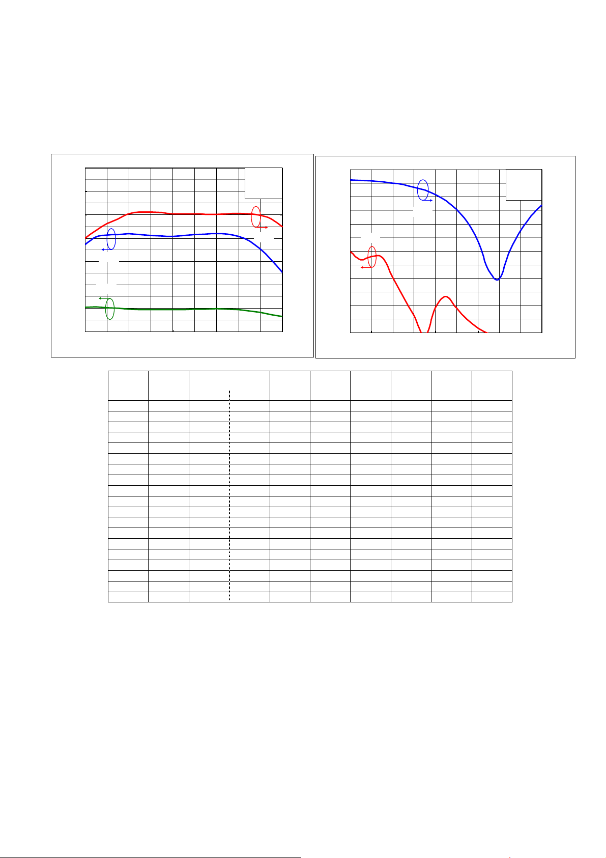
RD09MUP2 Output Power, Drain Efficiency vs. Frequency
(@ f=400 – 527MHz, Pin=1W, Vdd=7.2V, Idq=1A)
AN-UHF-072-C
14
12
10
8
Po
6
Drain Current Idd(A)
Output Power Po(W) ,
4
Idd
2
0
370 390 410 430 450 470 490 510 530 550
Frequency(M Hz)
Freq. Vgg Output Power Gp Idd ηd
(MHz) (V) (dBm) (W) (dB) (A) (%) (dB) (dBc) (dBc)
370 2.4 38.7 7.4 8.7 2.08 50.0 -1.9 -30.2 <-60
380 2.4 39.1 8.1 9.1 2.12 53.3 -2.0 -33.2 <-60
390 2.4 39.2 8.2 9.1 2.05 56.1 -2.1 -32.0 <-60
400 2.4 39.2 8.3 9.2 1.99 58.1 -2.3 -32.3 <-60
410 2.4 39.2 8.4 9.2 1.94 60.2 -2.5 -39.8 <-60
420 2.4 39.2 8.3 9.2 1.90 61.1 -2.8 -46.8 <-60
430 2.4 39.1 8.2 9.1 1.88 61.1 -3.2 -53.7 <-60
440 2.4 39.1 8.2 9.1 1.87 60.9 -3.8 <-60 <-60
450 2.4 39.1 8.1 9.1 1.88 60.3 -4.6 -50.7 <-60
460 2.4 39.2 8.2 9.2 1.91 60.3 -5.7 -46.7 <-60
470 2.4 39.2 8.3 9.2 1.93 60.3 -7.3 -50.8 <-60
480 2.4 39.2 8.4 9.2 1.94 60.1 -9.6 -55.2 <-60
490 2.4 39.2 8.4 9.2 1.95 60.2 -13.2 -58.3 <-60
500 2.4 39.2 8.3 9.2 1.93 60.3 -18.5 <-60 <-60
510 2.4 39.1 8.1 9.1 1.88 60.5 -20.1 <-60 <-60
520 2.4 38.9 7.7 8.9 1.79 60.4 -15.0 <-60 <-60
530 2.4 38.5 7.1 8.5 1.65 59.8 -11.2 <-60 <-60
540 2.4 37.9 6.1 7.9 1.47 58.1 -8.5 <-60 <-60
550 2.4 37.0 5.1 7.0 1.29 54.8 -6.6 <-60 <-60
Pin=1W
Vdd=7. 2V
Idq=1A
ηd
80
70
60
50
40
Drain Efficiency ηd(% )
30
20
10
0
-10
R.L
-20
2fo
-30
-40
2nd Harmonic 2fo(dBc )
-50
-60
370 390 410 430 450 470 490 510 530 550
Frequenc y(MHz)
Pin=1W
Vdd=7.2V
Idq= 1A
0
-5
-10
-15
-20
-25
-30
Return Loss R.L(dB)
Return
Loss
2fo 3fo
Application Note for Silicon RF Power Semiconductors
2/10
Page 3
RD09MUP2 single-stage amplifier RF performance at f=400-527MHz,Vdd=7.2V
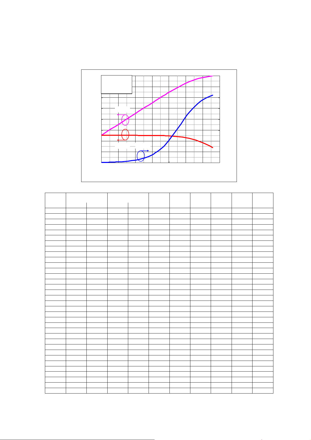
RD09MUP2 Output Power, Power Gain, Drain Efficiency vs. Input Power
(@ f=400MHz, Vdd=7.2V, Idq=1A)
AN-UHF-072-C
40
f=400MHz
Vdd=7.2V
35
Idq=1A
30
25
20
15
Power Gain GP(dB)
Output Power P o(dBm) ,
10
5
0
0 5 10 15 20 25 30 35
Po
GP
ηd
Input Power Pin(dBm)
80
70
60
50
40
30
20
10
0
Drain Efficiency ηd (%)
Vgg Pin Pin Output Power Gp Idd ηd
(V) (dBm) (W) (dBm) (W) (dB) (A) (%) (dB) (dBc) (dBc)
2.4 0.0 0.00 12.7 0.0 12.7 1.03 0.2 -2.8 <-60 <-60
2.4 1.0 0.00 13.6 0.0 12.6 1.03 0.3 -2.8 <-60 <-60
2.4 2.0 0.00 14.6 0.0 12.6 1.04 0.4 -2.8 <-60 <-60
2.4 3.0 0.00 15.6 0.0 12.6 1.04 0.5 -2.8 <-60 <-60
2.4 4.0 0.00 16.6 0.0 12.6 1.04 0.6 -2.8 -50.0 <-60
2.4 5.0 0.00 17.6 0.1 12.6 1.04 0.8 -2.8 -49.3 <-60
2.4 6.0 0.00 18.6 0.1 12.6 1.04 1.0 -2.8 -49.7 <-60
2.4 7.0 0.01 19.6 0.1 12.6 1.04 1.2 -2.8 -48.7 <-60
2.4 8.0 0.01 20.6 0.1 12.6 1.04 1.5 -2.8 -48.8 <-60
2.4 9.0 0.01 21.6 0.1 12.6 1.05 1.9 -2.8 -48.0 <-60
2.4 10.0 0.01 22.6 0.2 12.6 1.05 2.4 -2.8 -46.8 <-60
2.4 11.0 0.01 23.6 0.2 12.6 1.05 3.0 -2.8 -46.3 <-60
2.4 12.0 0.02 24.6 0.3 12.6 1.05 3.8 -2.8 -44.8 <-60
2.4 13.0 0.02 25.6 0.4 12.6 1.06 4.7 -2.8 -44.3 <-60
2.4 14.0 0.03 26.5 0.5 12.5 1.06 5.9 -2.8 -43.5 <-60
2.4 15.0 0.03 27.5 0.6 12.5 1.07 7.3 -2.8 -42.3 <-60
2.4 16.0 0.04 28.5 0.7 12.5 1.08 9.2 -2.7 -41.2 <-60
2.4 17.0 0.05 29.5 0.9 12.5 1.09 11.3 -2.7 -40.0 <-60
2.4 18.0 0.06 30.5 1.1 12.5 1.11 13.9 -2.7 -39.0 <-60
2.4 19.0 0.08 31.4 1.4 12.4 1.13 17.0 -2.7 -37.7 <-60
2.4 20.0 0.10 32.3 1.7 12.3 1.16 20.5 -2.7 -36.3 <-60
2.4 21.0 0.13 33.3 2.1 12.3 1.20 24.6 -2.7 -34.8 <-60
2.4 22.0 0.16 34.2 2.6 12.2 1.25 29.1 -2.7 -33.5 <-60
2.4 23.0 0.20 35.0 3.2 12.0 1.31 33.5 -2.7 -32.3 <-60
2.4 24.0 0.25 35.8 3.8 11.8 1.40 37.9 -2.6 -31.8 <-60
2.4 25.0 0.32 36.6 4.5 11.6 1.49 42.2 -2.6 -32.0 <-60
2.4 26.0 0.40 37.3 5.3 11.3 1.60 46.3 -2.6 -32.7 <-60
2.4 27.0 0.50 37.9 6.1 10.9 1.70 49.8 -2.5 -33.2 <-60
2.4 28.0 0.63 38.4 6.9 10.4 1.81 52.9 -2.4 -33.5 <-60
2.4 29.0 0.79 38.8 7.6 9.8 1.90 55.5 -2.4 -33.0 <-60
2.4 30.0 1.00 39.2 8.3 9.2 1.99 57.7 -2.3 -32.3 <-60
2.4 31.0 1.26 39.5 8.9 8.5 2.07 59.5 -2.2 -31.5 <-60
2.4 32.0 1.59 39.7 9.4 7.7 2.14 60.9 -2.1 -30.5 <-60
2.4 33.0 2.00 39.9 9.9 6.9 2.20 62.2 -2.0 -29.8 <-60
Return
Loss 2fo 3fo
Application Note for Silicon RF Power Semiconductors
3/10
Page 4

RD09MUP2 single-stage amplifier RF performance at f=400-527MHz,Vdd=7.2V
RD09MUP2 Output Power, Power Gain, Drain Efficiency vs. Input Power
(@ f=470MHz, Vdd=7.2V, Idq=1A)
AN-UHF-072-C
40
f=470MHz
Vdd=7.2V
35
Idq=1A
30
25
20
15
Power Gain GP(dB)
10
Output Power Po(dBm) ,
5
0
0 5 10 15 20 25 30 35
Po
ηdGP
Input Power Pin(dBm)
80
70
60
50
40
30
20
10
0
Drain Efficiency ηd (%)
Pin Pin Output Power Gp Idd ηd
(V) (dBm) (W) (dBm) (W) (dB) (A) (%) (dB) (dBc) (dBc)
2.4 0.0 0.00 14.4 0.0 14.4 1.04 0.4 -8.5 <-60 <-60
2.4 1.0 0.00 15.4 0.0 14.4 1.04 0.5 -9.0 <-60 <-60
2.4 2.0 0.00 16.4 0.0 14.4 1.04 0.6 -9.1 <-60 <-60
2.4 3.0 0.00 17.4 0.1 14.4 1.04 0.7 -9.0 <-60 <-60
2.4 4.0 0.00 18.3 0.1 14.3 1.04 0.9 -8.1 <-60 <-60
2.4 5.0 0.00 19.4 0.1 14.4 1.04 1.1 -8.1 <-60 <-60
2.4 6.0 0.00 20.4 0.1 14.3 1.04 1.4 -8.1 <-60 <-60
2.4 7.0 0.01 21.4 0.1 14.4 1.05 1.8 -8.1 <-60 <-60
2.4 8.0 0.01 22.4 0.2 14.4 1.05 2.3 -8.1 <-60 <-60
2.4 9.0 0.01 23.3 0.2 14.3 1.05 2.9 -8.1 <-60 <-60
2.4 10.0 0.01 24.3 0.3 14.3 1.05 3.6 -8.1 <-60 <-60
2.4 11.0 0.01 25.3 0.3 14.3 1.05 4.5 -8.1 <-60 <-60
2.4 12.0 0.02 26.3 0.4 14.3 1.06 5.6 -8.1 <-60 <-60
2.4 13.0 0.02 27.3 0.5 14.3 1.06 7.0 -8.1 <-60 <-60
2.4 14.0 0.03 28.3 0.7 14.3 1.07 8.8 -8.1 <-60 <-60
2.4 15.0 0.03 29.3 0.8 14.3 1.08 10.9 -8.1 <-60 <-60
2.4 16.0 0.04 30.3 1.1 14.3 1.09 13.6 -8.0 <-60 <-60
2.4 17.0 0.05 31.2 1.3 14.2 1.10 16.8 -8.1 <-60 <-60
2.4 18.0 0.06 32.2 1.7 14.2 1.12 20.7 -8.1 <-60 <-60
2.4 19.0 0.08 33.2 2.1 14.2 1.15 25.1 -8.1 <-60 <-60
2.4 20.0 0.10 34.1 2.6 14.1 1.18 30.1 -8.1 <-60 <-60
2.4 21.0 0.13 35.0 3.2 14.0 1.24 35.5 -8.2 <-60 <-60
2.4 22.0 0.16 35.8 3.8 13.8 1.30 40.5 -8.3 <-60 <-60
2.4 23.0 0.20 36.5 4.5 13.5 1.39 45.2 -8.4 <-60 <-60
2.4 24.0 0.25 37.1 5.2 13.1 1.47 49.0 -8.5 <-60 <-60
2.4 25.0 0.32 37.6 5.8 12.6 1.56 51.9 -8.5 <-60 <-60
2.4 26.0 0.40 38.1 6.4 12.1 1.64 54.3 -8.3 -57.0 <-60
2.4 27.0 0.50 38.4 7.0 11.4 1.72 56.1 -8.1 -54.5 <-60
2.4 28.0 0.63 38.7 7.4 10.7 1.80 57.5 -7.8 -52.7 <-60
2.4 29.0 0.79 39.0 7.9 10.0 1.86 58.7 -7.6 -51.7 <-60
2.4 30.0 1.00 39.2 8.3 9.2 1.93 59.8 -7.3 -50.7 <-60
2.4 31.0 1.26 39.4 8.6 8.4 1.98 60.6 -7.1 -50.2 <-60
2.4 32.0 1.58 39.5 9.0 7.5 2.03 61.5 -6.9 -49.7 <-60
2.4 33.0 2.00 39.5 9.0 6.5 2.03 61.4 -6.9 -49.7 <-60
Return
Loss 2fo 3fo
Application Note for Silicon RF Power Semiconductors
4/10
Page 5

RD09MUP2 single-stage amplifier RF performance at f=400-527MHz,Vdd=7.2V
RD09MUP2 Output Power, Power Gain, Drain Efficiency vs. Input Power
(@ f=527MHz, Vdd=7.2V, Idq=1A)
AN-UHF-072-C
40
f=527MHz
Vdd=7.2V
35
Idq=1A
30
GP
Po
ηd
Input Power Pin(dBm)
25
20
15
Power Gain GP(dB)
10
Output Power P o(dBm) ,
5
0
0 5 10 15 20 25 30 35
80
70
60
50
40
30
20
10
0
Drain Efficiency ηd (%)
Vgg Pin Pin Output Power Gp Idd ηd
(V) (dBm) (W) (dBm) (W) (dB) (A) (%) (dB) (dBc) (dBc)
2.4 0.0 0.00 13.8 0.0 13.8 1.03 0.3 -22.0 <-60 <-60
2.4 1.0 0.00 14.8 0.0 13.8 1.04 0.4 -16.0 <-60 <-60
2.4 2.0 0.00 15.8 0.0 13.8 1.04 0.5 -15.9 <-60 <-60
2.4 3.0 0.00 16.8 0.0 13.8 1.04 0.6 -15.8 <-60 <-60
2.4 4.0 0.00 17.8 0.1 13.8 1.04 0.8 -15.6 <-60 <-60
2.4 5.0 0.00 18.7 0.1 13.8 1.04 1.0 -15.4 <-60 <-60
2.4 6.0 0.00 19.8 0.1 13.8 1.04 1.3 -15.5 <-60 <-60
2.4 7.0 0.01 20.8 0.1 13.8 1.04 1.6 -15.5 <-60 <-60
2.4 8.0 0.01 21.8 0.2 13.8 1.05 2.0 -15.4 <-60 <-60
2.4 9.0 0.01 22.8 0.2 13.8 1.05 2.5 -15.4 <-60 <-60
2.4 10.0 0.01 23.7 0.2 13.7 1.05 3.1 -14.8 <-60 <-60
2.4 11.0 0.01 24.7 0.3 13.7 1.05 3.9 -14.5 <-60 <-60
2.4 12.0 0.02 25.7 0.4 13.7 1.05 4.9 -14.5 <-60 <-60
2.4 13.0 0.02 26.7 0.5 13.7 1.06 6.2 -14.5 <-60 <-60
2.4 14.0 0.03 27.7 0.6 13.7 1.06 7.7 -14.5 <-60 <-60
2.4 15.0 0.03 28.7 0.7 13.7 1.07 9.7 -14.5 <-60 <-60
2.4 16.0 0.04 29.7 0.9 13.7 1.07 12.0 -14.5 <-60 <-60
2.4 17.0 0.05 30.7 1.2 13.7 1.08 15.0 -14.5 <-60 <-60
2.4 18.0 0.06 31.7 1.5 13.7 1.10 18.5 -14.6 <-60 <-60
2.4 19.0 0.08 32.6 1.8 13.6 1.12 22.9 -14.6 <-60 <-60
2.4 20.0 0.10 33.6 2.3 13.6 1.14 28.0 -14.7 <-60 <-60
2.4 21.0 0.13 34.5 2.8 13.5 1.17 33.2 -14.9 <-60 <-60
2.4 22.0 0.16 35.3 3.4 13.3 1.22 38.9 -15.0 <-60 <-60
2.4 23.0 0.20 36.1 4.0 13.1 1.27 44.1 -15.3 <-60 <-60
2.4 24.0 0.25 36.7 4.7 12.7 1.34 48.4 -15.7 <-60 <-60
2.4 25.0 0.32 37.2 5.2 12.2 1.40 51.8 -16.0 <-60 <-60
2.4 26.0 0.40 37.6 5.7 11.6 1.46 54.3 -15.9 <-60 <-60
2.4 27.0 0.50 37.9 6.2 10.9 1.53 56.3 -15.3 <-60 <-60
2.4 28.0 0.63 38.2 6.6 10.2 1.59 57.7 -14.4 <-60 <-60
2.4 29.0 0.79 38.4 7.0 9.4 1.65 58.7 -13.4 <-60 <-60
2.4 30.0 1.00 38.6 7.3 8.6 1.70 59.7 -12.3 <-60 <-60
2.4 31.0 1.26 38.8 7.6 7.8 1.74 60.5 -11.2 <-60 <-60
2.4 32.0 1.58 39.0 7.9 7.0 1.79 61.2 -10.2 <-60 <-60
2.4 33.0 2.00 39.0 7.9 6.0 1.79 61.4 -10.1 <-60 <-60
Return
Loss 2fo 3fo
Application Note for Silicon RF Power Semiconductors
5/10
Page 6

RD09MUP2 single-stage amplifier RF performance at f=400-527MHz,Vdd=7.2V
)
RD09MUP2 Output Power, Drain Current, Drain Efficiency vs. Drain Voltage
(@ f=400MHz, Pin=1W, Idq=1A)
AN-UHF-072-C
14
f=400MHz , Pin=1W
Idq=1A
12
10
8
ηd
Po
6
4
Drain Current Idd(A)
Output Power Po(W) ,
Idd
2
0
80
70
60
50
40
30
20
10
Drain Efficiency ηd(%
345678910
Drain Voltage Vdd(V)
Vdd Vgg Output Power Idd ηd
(V) (V) (dBm) (W) (A) (%) (dB) (dBc) (dBc)
3.0 2.4 32.9 1.9 1.08 60.6 -1.7 -26.3 <-60
3.5 2.4 34.1 2.6 1.21 60.8 -1.7 -27.2 <-60
4.0 2.4 35.1 3.3 1.34 61.0 -1.8 -27.7 <-60
4.5 2.4 36.0 4.0 1.46 60.9 -1.9 -28.5 <-60
5.0 2.4 36.8 4.7 1.58 60.6 -2.0 -29.3 <-60
5.5 2.4 37.4 5.6 1.69 60.3 -2.1 -30.2 <-60
6.0 2.4 38.0 6.4 1.78 59.8 -2.1 -30.5 <-60
6.5 2.4 38.6 7.2 1.87 59.2 -2.2 -31.5 <-60
7.0 2.4 39.0 8.0 1.96 58.6 -2.3 -32.0 <-60
7.5 2.4 39.4 8.8 2.04 57.7 -2.3 -32.3 <-60
8.0 2.4 39.8 9.5 2.10 56.7 -2.3 -32.5 <-60
8.5 2.4 40.1 10.2 2.17 55.5 -2.4 -32.0 <-60
9.0 2.4 40.3 10.8 2.22 54.3 -2.4 -31.7 <-60
9.5 2.4 40.6 11.4 2.27 53.0 -2.4 -31.2 <-60
10.0 2.4 40.7 11.9 2.31 51.6 -2.5 -30.5 <-60
Return
Loss 2fo 3fo
Application Note for Silicon RF Power Semiconductors
6/10
Page 7

RD09MUP2 single-stage amplifier RF performance at f=400-527MHz,Vdd=7.2V
RD09MUP2 Output Power, Drain Current, Drain Efficiency vs. Drain Voltage
(@ f=470MHz, Pin=1W, Idq=1A)
AN-UHF-072-C
14
f=470MHz , Pin=1W
Idq=1A
12
10
8
6
Drain Current Idd(A)
4
Output Power Po(W) ,
2
0
345678910
ηd
Po
Idd
Drain Voltage Vdd(V)
80
70
60
50
40
30
20
10
Drain Efficiency ηd(%)
Vdd Vgg Output Power Idd ηd
(V) (V) (dBm) (W) (A) (%) (dB) (dBc) (dBc)
3.0 2.4 32.6 1.8 1.04 58.6 -5.9 -47.3 <-60
3.5 2.4 33.8 2.4 1.16 58.9 -6.1 -47.5 <-60
4.0 2.4 34.8 3.0 1.28 59.2 -6.3 -47.8 <-60
4.5 2.4 35.7 3.7 1.39 59.5 -6.5 -48.5 <-60
5.0 2.4 36.5 4.4 1.50 59.6 -6.7 -48.8 <-60
5.5 2.4 37.2 5.3 1.61 59.8 -6.8 -49.2 <-60
6.0 2.4 37.9 6.1 1.71 59.9 -7.0 -49.7 <-60
6.5 2.4 38.4 7.0 1.80 60.0 -7.1 -50.0 <-60
7.0 2.4 39.0 7.9 1.89 60.1 -7.3 -50.5 <-60
7.5 2.4 39.5 8.9 1.98 60.1 -7.4 -50.8 <-60
8.0 2.4 39.9 9.8 2.06 60.0 -7.5 -51.5 <-60
8.5 2.4 40.3 10.8 2.14 59.8 -7.6 -52.3 <-60
9.0 2.4 40.7 11.8 2.21 59.6 -7.6 -52.7 <-60
9.5 2.4 41.1 12.8 2.28 59.4 -7.7 -53.5 <-60
10.0 2.4 41.4 13.8 2.35 59.0 -7.7 -53.8 <-60
Return
Loss 2fo 3fo
Application Note for Silicon RF Power Semiconductors
7/10
Page 8

RD09MUP2 single-stage amplifier RF performance at f=400-527MHz,Vdd=7.2V
RD09MUP2 Output Power, Drain Current, Drain Efficiency vs. Drain Voltage
(@ f=527MHz, Pin=1W, Idq=1A)
AN-UHF-072-C
14
f=527MHz , Pin=1W
Idq=1A
12
10
8
6
Drain Current Idd(A)
4
Output Power Po(W) ,
2
0
ηd
Po
Idd
345678910
Drain Voltage Vdd(V)
80
70
60
50
40
30
20
10
Drain Efficiency ηd(%)
Vdd Vgg Output Power Idd ηd
(V) (V) (dBm) (W) (A) (%) (dB) (dBc) (dBc)
3.0 2.4 32.0 1.6 0.92 57.3 -7.3 <-60 <-60
3.5 2.4 33.1 2.1 1.02 58.0 -7.7 <-60 <-60
4.0 2.4 34.2 2.6 1.13 58.4 -8.2 <-60 <-60
4.5 2.4 35.1 3.2 1.23 58.8 -8.8 <-60 <-60
5.0 2.4 35.9 3.9 1.32 59.2 -9.3 <-60 <-60
5.5 2.4 36.6 4.6 1.41 59.5 -9.9 <-60 <-60
6.0 2.4 37.3 5.4 1.50 59.7 -10.5 <-60 <-60
6.5 2.4 37.9 6.1 1.59 59.9 -11.2 <-60 <-60
7.0 2.4 38.5 7.0 1.67 60.1 -11.9 <-60 <-60
7.5 2.4 39.0 7.9 1.75 60.2 -12.6 <-60 <-60
8.0 2.4 39.4 8.8 1.83 60.2 -13.3 <-60 <-60
8.5 2.4 39.9 9.7 1.91 60.1 -14.0 <-60 <-60
9.0 2.4 40.3 10.6 1.98 59.9 -14.8 <-60 <-60
9.5 2.4 40.6 11.5 2.04 59.7 -15.5 <-60 <-60
10.0 2.4 41.0 12.5 2.11 59.4 -16.1 <-60 <-60
Return
Loss 2fo 3fo
Application Note for Silicon RF Power Semiconductors
8/10
Page 9

RD09MUP2 single-stage amplifier RF performance at f=400-527MHz,Vdd=7.2V
RD09MUP2 Equivalent Circuit (@f=400-527MHz)
AN-UHF-072-C
WW
Note:Board material – Glass-Epoxy Substrate. Microstrip line width=1.3mm/50 OHM,er:4.8,t=0.8mm. W:Line width=1.0mm.
Parts Type Value Type name Vender
C1 330pF GRM2162C1H331JA01D Murata Manufacturing Co.,Ltd.
C2 5pF GRM2162C1H5R0CD01D Murata Manufacturing Co.,Ltd.
C3 33pF GRM2162C1H330JZ01D Murata Manufacturing Co.,Ltd.
C4 33pF GRM2162C1H330JZ01D Murata Manufacturing Co.,Ltd.
C5 24pF GRM2162C1H240JZ01D Murata Manufacturing Co.,Ltd.
Capacitor
Resistance R1 4.7K OHM CR20-472JB Hokuriku Electric Industry Co.,Ltd.
L1
C6 30pF GRM2162C1H300JZ01D Murata Manufacturing Co.,Ltd.
C7 20pF GRM2162C1H200JZ01D Murata Manufacturing Co.,Ltd.
C8 11pF GRM2162C1H110JZ01D Murata Manufacturing Co.,Ltd.
C9 330pF GRM2162C1H331JA01D Murata Manufacturing Co.,Ltd.
C10 4700pF GRM216R11H472KA01D Murata Manufacturing Co.,Ltd.
C11 4700pF GRM216R11H472KA01D Murata Manufacturing Co.,Ltd.
C12 22µF UVZ1H220MDD NICHICON CORPORATION
43.7nH Enameled wire 6Turns,
Diameter:0.43mm,φ2.46mm(the out side
diameter)
4006A yc corporation Co.,Ltd.
Application Note for Silicon RF Power Semiconductors
9/10
Page 10

RD09MUP2 single-stage amplifier RF performance at f=400-527MHz,Vdd=7.2V
RD09MUP2 test fixture (@f=400- 527MHz)
AN-UHF-072-C
RF-in
GND
Vgg
Device is soldered to the
Reverse side of a substrate
Through hole
Vdd
GND
RF-out
Front side View
Device
Reverse side View
Thermal sheet
Heat sink View
Application Note for Silicon RF Power Semiconductors
10/10
 Loading...