

Mitsubishi Electric a2, AL2-MR-A, AL2-MR-D Programming Manual
PROGRAMMING MANUAL
α
2
SIMPLE APPLICATION CONTROLLER

α2 Simple Application Controllers
Foreword
• This manual contains text, diagrams and explanations which will guide the reader in the
correct programming and operation of the
• Before attempting to install or use the
understood.
• If in doubt at any stage of the installation of the
professional electrical engineer who is qualified and trained to local and national standards
which apply to the installation site.
• If in doubt about the operation or use of the
Mitsubishi Electric distributor.
• This manual is subject to change without notice.
2
series controller.
α
2
Series Controller this manual should be read and
α
2
Series Controller always consult a
α
2
Series Controller please consult the nearest
α

α
2 Simple Application Controllers
α2 SIMPLE APPLICATION
CONTROLLERS
PROGRAMMING MANUAL
Manual number : JY992D97101
Manual revision : B
Date : Oct. 2003
i

α
2 Simple Application Controllers
FAX BACK
Mitsubishi has a world wide reputation for its efforts in continually developing and pushing back
the frontiers of industrial automation. What is sometimes overlooked by the user is the care
and attention to detail that is taken with the documentation. However, to continue this process
of improvement, the comments of the Mitsubishi users are always welcomed. This page has
been designed for you, the reader, to fill in your comments and fax them back to us. We look
forward to hearing from you.
Fax numbers: Your name: ...................................................
Mitsubishi Electric.... .....................................................................
America (01) 847-478-2253 Your company: .............................................
Australia (02) 638-7072 .....................................................................
Germany (0 21 02) 4 86-1 12 Your location:................................................
Spain (34) 93-589-1579 .....................................................................
United Kingdom (01707) 278-695
Please tick the box of your choice
What condition did the manual arrive in?
Will you be using a folder to store the manual?
What do you think to the manual presentation?
Are the explanations understandable?
Which explanation was most difficult to understand: ..................................................................
....................................................................................................................................................
Are there any diagrams which are not clear?
If so,which: ..................................................................................................................................
What do you think to the manual layout?
If there one thing you would like to see improved, what is it? .....................................................
....................................................................................................................................................
....................................................................................................................................................
Could you find the information you required easily using the index and/or the contents, if
possible please identify your experience: ...................................................................................
....................................................................................................................................................
....................................................................................................................................................
....................................................................................................................................................
....................................................................................................................................................
!
!
!
!
!
!
Good
Ye s
Tidy
Ye s
Ye s
Good
Minor damage
!
No
!
Unfriendly
!
Not too bad
!
No
!
Not too bad
!
Unusable
!
Unusable
!
Unhelpful
!
Do you have any comments in general about the Mitsubishi manuals? .....................................
....................................................................................................................................................
....................................................................................................................................................
....................................................................................................................................................
....................................................................................................................................................
Thank you for taking the time to fill out this questionnaire. We hope you found both the product
and this manual easy to use.
ii
α
2 Simple Application Controllers
Guidelines for the safety of the user and protection of
α
2 Simple Application
controllers
This manual provides information for the use of α2 Simple Application controllers. The manual
has been written to be used by trained and competent personnel. The definition of such a
person or persons is as follows;
a) Any engineer who is responsible for the planning, design and construction of automatic
equipment using the product associated with this manual should be of a competent
nature, trained and qualified to the local and national standards required to fulfill that
role. These engineers should be fully aware of all aspects of safety with regards to
automated equipment.
b) Any commissioning or service engineer must be of a competent nature, trained and
qualified to the local and national standards required to fulfill that job. These engineers
should also be trained in the use and maintenance of the completed product. This
includes being completely familiar with all associated documentation for the said product.
All maintenance should be carried out in accordance with established safety practices.
c) All operators of the completed equipment (see Note) should be trained to use this
product in a safe manner in compliance to established safety practices. The operators
should also be familiar with documentation which is associated with the operation of the
completed equipment.
Note :
Note: the term ‘completed equipment’ refers to a third party constructed device which
contains or uses the product associated with this manual.
Notes on the Symbols Used in this Manual
At various times throughout this manual certain symbols will be used to highlight points of
information which are intended to ensure the users personal safety and protect the integrity of
equipment. Whenever any of the following symbols are encountered its associated note must
be read and understood. Each of the symbols used will now be listed with a brief description of
its meaning.
Hardware warnings
1 ) Indicates that the identified danger
2 ) Indicates that the identified danger could
damage.
3 ) Indicates a point of further interest or further explanation.
Software warning
4 ) Indicates special care must be taken when using this element of software.
WILL
cause physical and property damage.
POSSIBLY
cause physical and property
5 ) Indicates a special point which the user of the associate software element should
be aware of.
6 ) Indicates a point of interest or further explanation.
iii

2
α
Simple Application Controllers
iv

α
2 Simple Application Controllers
Table of Contents
Safety Guidelines ................................................................................ iii
1. Introduction ............................................................................... 1-1
1.1 Special Features of the Controller ........................................................1-1
1.2 Model Name .......................................................................................... 1-2
2. Function Block Programming ....................................................2-1
2.1 Block Type and the FBD base .............................................................. 2-1
2.1.1 Inputs ...........................................................................................2-2
2.1.2 Front Panel Keys ..........................................................................2-2
2.1.3 System Memory Bits .................................................................... 2-3
2.1.4 Function Blocks ............................................................................ 2-3
2.1.5 Outputs ........................................................................................2-4
2.1.6 Function Block Diagram (FBD) base ............................................ 2-4
2.2 Programming Methods ..........................................................................2-5
2.2.1 Direct Programming ..................................................................... 2-5
2.2.2 AL-PCS/WIN-E Programming Software Ver 2.00 and upwards ...2-5
3. System Menu ............................................................................ 3-1
3.1 Menu Options Instructions .................................................................... 3-1
3.2 The Stop Mode ..................................................................................... 3-2
3.2.1 Top Menu ..................................................................................... 3-2
3.2.2 The “Others... ............................................................................... 3-4
3.3 The Run Mode Top Menu ................................................................... 3-10
3.4 The Edit Menu ..................................................................................... 3-15
3.5 The Function Block Edit Menu ............................................................ 3-15
3.6 Option Screen Setup ........................................................................... 3-16
3.6.1 ProgEdit .....................................................................................3-16
3.6.2 Change the Language Setting ................................................... 3-16
3.6.3 ClockSET ................................................................................... 3-16
3.6.4 RadioClock - DCF77 Decoding ..................................................3-17
3.6.5 SummerTime .............................................................................. 3-18
3.6.6 DispPass .................................................................................... 3-19
3.6.7 Password ................................................................................... 3-20
3.6.8 Serial Com .................................................................................3-20
3.6.9 Memory cassette ........................................................................3-21
3.6.10 Analog Inputs ...........................................................................3-22
3.7 LCD Displays ...................................................................................... 3-23
3.7.1 Image Table ............................................................................... 3-23
3.7.2 LCD Function ............................................................................. 3-23
3.8 Block Items .........................................................................................3-24
3.8.1 Input Blocks ...............................................................................3-24
3.8.2 Function Blocks .......................................................................... 3-24
3.8.3 Output Blocks ............................................................................. 3-24
3.8.4 Connected Blocks ...................................................................... 3-24
v

α
2
Series Applications Controller
4. Direct Programming .................................................................. 4-1
4.1 Block Availability ................................................................................... 4-1
4.2 Connecting Blocks ................................................................................ 4-1
4.2.1 To connect the blocks from the left (signal provider) block to right
(signal receiver) block. ................................................................ 4-1
4.2.2 To connect the blocks from the right (signal receiver) block to left
(signal provider) block. ................................................................4-2
4.3 Disconnect Two Blocks ......................................................................... 4-2
4.4 Methods to Create a Function Block ..................................................... 4-3
4.4.1 New FB ........................................................................................ 4-3
4.4.2 AddFB .......................................................................................... 4-3
4.5 Function Block Editing ..........................................................................4-3
4.5.1 Setup Function Block ................................................................... 4-3
4.5.2 Change No. (of a Function Block) ................................................4-3
4.5.3 Delete FB ..................................................................................... 4-3
4.6 Movement between Function Blocks .................................................... 4-4
4.6.1 Movement Between Unconnected Blocks .................................... 4-4
4.6.2 Movement Between Connected Blocks .......................................4-4
4.6.3 The Jump Command .................................................................... 4-4
4.7 Using Keys as Inputs ............................................................................4-4
4.8 The Monitor Mode .................................................................................4-5
4.8.1 Monitor/Update Function Block Values ........................................4-5
4.8.2 Forcing Outputs ON/OFF .............................................................4-6
4.8.3 Add/Delete Function Blocks in the Monitor Mode ........................ 4-6
5. The Logic Function Blocks ........................................................5-1
5.1 The AND Block ..................................................................................... 5-2
5.2 The OR Block ........................................................................................ 5-3
5.3 The NOT Block ..................................................................................... 5-4
5.4 The XOR Block (Exclusive OR) ............................................................ 5-4
5.5 The NAND Block (Not AND) ................................................................. 5-5
5.6 The NOR Block (Not OR) ......................................................................5-6
vi

α
2
Series Applications Controller
6. Function Blocks ......................................................................... 6-1
6.1 Definitions ............................................................................................. 6-6
6.2 Abbreviations ........................................................................................ 6-6
6.3 Boolean block .......................................................................................6-7
6.4 Set/Reset Block ....................................................................................6-9
6.5 Pulse Block ......................................................................................... 6-11
6.6 Alternate Block .................................................................................... 6-13
6.7 Delay Block ......................................................................................... 6-14
6.8 One Shot Block ................................................................................... 6-16
6.9 Flicker Block ........................................................................................ 6-18
6.10 TimeSW Block ..................................................................................6-21
6.10.1 Setting the First Time Switch ................................................... 6-21
6.10.2 For the Date operation: ............................................................ 6-22
6.10.3 For the Weekly Operation: ....................................................... 6-22
6.10.4 To Enter New Time Switches ................................................... 6-22
6.10.5 To Edit Time Switches ............................................................. 6-23
6.10.6 To Delete Time Switch Data .................................................... 6-23
6.11 Counter Block ................................................................................... 6-24
6.12 Up/Down Counter Block .................................................................... 6-25
6.13 Compare Block ................................................................................. 6-27
6.14 Analog Output ................................................................................... 6-29
6.15 OFFSET Block ..................................................................................6-32
6.16 Display Block .................................................................................... 6-35
6.16.1 Displaying Data Onscreen ....................................................... 6-35
6.16.2 Editing Data Onscreen .............................................................6-36
6.17 Zone Compare Block ........................................................................6-39
6.18 Schmitt Trigger Block ........................................................................ 6-41
6.19 Hour Meter Block ..............................................................................6-44
6.20 Speed Detect Block .......................................................................... 6-46
6.21 Pulse Width Modulation ....................................................................6-51
6.22 PID Block .......................................................................................... 6-53
6.22.1 Parameter List and PID Details. ............................................... 6-54
6.22.2 Setting the Input Values, SV and PV ....................................... 6-56
6.22.3 Setting the Function Block Parameters .................................... 6-56
6.22.4 Limiting the Manipulated Value ................................................6-59
6.22.5 Setting KP, TI, and TD with Auto-tuning .................................. 6-60
6.22.6 PID Troubleshooting ................................................................ 6-61
6.22.7 Error Codes .............................................................................. 6-62
6.23 Retentive Alternate Block .................................................................. 6-67
6.24 Addition Block ................................................................................... 6-68
6.25 Subtraction Block ..............................................................................6-69
6.26 Multiplication Block ...........................................................................6-70
6.27 Division Block .................................................................................... 6-71
6.28 Calculation Block ..............................................................................6-72
6.29 Shift Block ......................................................................................... 6-74
vii

α
2
Series Applications Controller
6.30 GSM/SMS Block ...............................................................................6-76
6.30.1 Input Signal ..............................................................................6-78
6.30.2 Output Signal ...........................................................................6-78
6.30.3 Word Output ............................................................................. 6-78
6.30.4 Short Message Service (SMS) ................................................ 6-79
6.30.5 Comment/Signal Number .........................................................6-79
6.30.6 Setting ...................................................................................... 6-79
6.30.7 Destination ............................................................................... 6-79
6.30.8 SMS Setting Dialog Box ...........................................................6-80
6.30.9 SMS Service Center ................................................................6-80
6.30.10 Valid Period ............................................................................6-80
6.30.11 Destination ............................................................................. 6-80
6.30.12 Error Messages ......................................................................6-81
6.31 Random One Shot Block ..................................................................6-87
6.32 Delayed One Shot Block ................................................................... 6-89
6.33 Delayed Alternate Block .................................................................... 6-92
6.34 Retentive Set Reset Block ................................................................ 6-94
6.35 Control Display Manager ..................................................................6-96
6.35.1 Operation Image: ..................................................................... 6-97
6.35.2 To Set Display Manager: .......................................................... 6-98
6.36 Connect Block .................................................................................6-104
7. Let’s Make a Program ...............................................................7-1
7.1 Option Settings .....................................................................................7-1
7.2 The Function Block Diagram .................................................................7-1
7.3 Input the Program .................................................................................7-2
7.3.1 Adding Function Blocks by the Left to Right method
(Section 4.2.1) ............................................................................. 7-2
7.3.2 Scroll through the Function Blocks by Number (Section 4.6.1) ....7-3
7.3.3 Use the Jump Command (Section 4.6.3) .....................................7-3
7.3.4 Use the NewFB command ........................................................... 7-4
7.3.5 Connect the Function Blocks from Right to Left (Section 4.2.2) .. 7-4
7.4 Set up the Function Block Parameters (Section 4.5.1) ......................... 7-5
7.5 Exit the Function Block Diagram board .................................................7-6
8. Appendix ...................................................................................8-1
8.1 Associated Manuals .............................................................................. 8-1
8.2 System Keys ......................................................................................... 8-2
8.3 System Bits ........................................................................................... 8-2
8.4 Boolean Gates ...................................................................................... 8-3
8.5 PID Formulas ........................................................................................ 8-9
viii

α
2 Simple Application Controllers
1. Introduction
The α2 Series Controllers provides supervisory control for use in the home, office, factory or
wherever you need it. The
applications:
Applications
The
2 Series is designed to be used for automatic applications including:
α
- Lighting, air-conditioning or watering control
- Opening and closing gates
- Security systems
- Domestic systems
- Temperature control
Introduction 1
2 Series Controllers offers flexible I/O control for varied
α
However, the
- Applications where high reliabilities such as nuclear power control, railway facilities,
airline facilities, vehicles, combustion equipment and medical equipment are required.
- Applications in life critical situations
Please contact a Mitsubishi distributor for more information.
2 Series Controllers is not designed to be used in the following applications:
α
1.1 Special Features of the Controller
1 ) Display messages and Function Block data
The
the LCD screen as a message. The
counters to be changed while in RUN mode.
- Total characters on LCD display: 12 characters x 4 lines
- Display items: Message, values (current or set) of timers and counters, analogue
2 ) Program Input
The user can program directly from the front panel or use the windows based
AL-PCS/WIN-E programming software Ver. 2.00 and upwards. Pictorial representations of
data are used to connect function blocks in both methods. Please refer to the
Manual for details on AL-PCS/WIN-E.
2 Series Controller can display the state of operation and the status of an alarm on
α
2 Series Controller allows the values of timers and
α
values, etc.
Software
α
3 ) Enhancement of clock function
The calendar timer function can switch inputs to time-dependent controls on a daily or
weekly basis.
4 ) Analog input, 0-10V/0-500
The DC input type for the
(50 divisions per volt).
5 ) High Speed Counter (max. 1kHz)
The
AL2-4EX EI1 and EI2.
2 Series Controller can have two dedicated high speed counters when using
α
2 Series accepts 0-10V signals with a digital range of 0-500
α
1 - 1

α
2 Simple Application Controllers
6 ) High current output
The Relay outputs can handle 8A per common (COM) in the main units: AL2-14MR-*
(O01-6); AL2-24MR-D (O01-04). Transistor outputs are 1A/point in the extension module.
7 ) GSM Function
The
E-mail account via a standard service provider.
8 ) Dedicated Protocol
The
enter current and set values in Function Blocks from a personal computer.
9 ) Built-in EEPROM
The built in EEPROM eliminates the need for battery backed data.
10 )Supports 6 languages
The system supports the following languages: English, German, French, Italian, Spanish
and Swedish.
11 ) LCD Screen
Enhanced LCD screen size displays data more clearly and enables the
Controller to display bar graphs and other new data representations.
2 Series Controller uses GSM to send an SMS to a mobile phone or a dedicated
α
2 Series Controllers introduces this concept allowing the user to monitor, modify and
α
Introduction 1
2 Series
α
12 )Increased Memory
The CPU memory for the
maximum of 200 function blocks.
This manual will describe front panel programming of the
function block capabilities, and the functions of the front panel keys.
1.2 Model Name
The α2 Series Controllers can be identified using the following format:
AL2 - Series Controller
** - Total number of I/O
M - Main Unit
2 Series Controller can store 5 kbyte of programming or a
α
2 Series Controllers, the powerful
α
AL2- ** M R - A/D
A - 100-240 VAC
D - 24 VDC
R - Relay Type Output
1 - 2

α
2 Simple Application Controllers
2. Function Block Programming
The α2 Series Controller is programmed with a user-friendly method of combining specialpurpose dedicated function blocks. The task is broken down into various stages which can be
represented by a number of function blocks. Function Block Programming simplifies
application representation but ensures complete process control. The program can be
developed in very simple steps but even a complex task can be represented in this way. For
ease of use, the function blocks have been preprogrammed to perform certain tasks yet offer
flexibility to be tailored to individual requirements.
Figure 1.1: Principle of Function Block Programming
B001
I01
S
OS
C
Function Block Programming 2
O01
One Shot
I02
I03
1
2
3
4
B002
OR
I0n - Input n
O0n - Output n
OR - OR Boolean Function Block
SR - Set/Reset Function Block
OS - One Shot Function Block
The user can build a complex circuit in small, easy steps by starting at the input and working
forward in a logical manner. The
2 will gather and process information and provide the
α
necessary control for the application according to the system algorithm. Each function block
provides specific control parameters, accessible by the user, to tailor each program for
complete application suitability. The function blocks are connected together to form a circuit
using the Function Block Diagram (FBD.)
2.1 Block Type and the FBD base
B003
S
SR
R
Set/Reset
O02
O03
There are seven sets of items that can be used in the function block program: Inputs, Front
Panel Keys, System Memory Bits, Logic Blocks, Function Blocks, User-defined Function
Blocks and Outputs. A brief description of each follows.
2 - 1

α
2 Simple Application Controllers
2.1.1 Inputs
The α2 Series Controller will accept both digital (On/Off) and analog (mV value based)
electrical information through the system Inputs. Please refer to the
electrical information, wiring diagrams and input specifications. Depending on the specific
controller there are either 14 or 24 input version types of the
are referenced to I01, I02, ..., I15.
Function Block Programming 2
2 Hardware Manual for
α
2 Series Controller. The Inputs
α
Table 2.1: Input type for the
Input Input Number Description
Signal I01 - I15 Maximum of 15 Inputs are allocated for use.
AS-i E01 - E04 Maximum of 4 AS-interface inputs are allocated for use.
Analog A01 - A08 Maximum of 8 Analog inputs are allocated for use on input I01 to I08.
Extension EI01 - EI04 Maximum of 4 Extension inputs are allocated for use.
2.1.2 Front Panel Keys
The front panel keys can enter data into the program memory, move through menus or
programs, select programming options, or be used as extra inputs when the program is
running. There are eight keys which are referenced as K01 - K08.
Table 2.2: Front panel keys for the α2 Series Controller
Key Name Key number Key Function
OK K01
ESC K02
“+” K03
“-” K04
( ) K05
( ) K06
( ) K07 Move to the right on the LCD display, FB program, or Jump command
( )
K08 Move to the left on the LCD display, FB program, or Jump command
2 Series Controller
α
Used to enter menu options, confirm data entry, and manually force
inputs ON/OFF in the monitor function.
Used to cancel an operation, move to a higher level screen, or to
move to a new menu.
Used to connect (or “add”) function blocks, increase Direct Set input
values or times, or move through programs or menus.
Used to disconnect function blocks, decrease Direct Set values or
times, or move through programs or menus.
Scroll up through menu options (menus, keys, FB, Inputs, Outputs,
etc.)
Scroll down through menu options (menus, keys, FB, Inputs, Outputs,
etc.)
If the front panel keys are used as auxiliary inputs on the FBD, their primary function, as front
panel display navigators, will be disabled.
2 - 2

α
2 Simple Application Controllers
2.1.3 System Memory Bits
These System Memory Bits can provide predefined signals - Always On, Always Off, 0.5
second On, 0.5 second Off, or provide information about the Real Time Clock time or errors
etc. There are 24 Memory bits that are referenced as M01, M02, ... M24.
Function Block Programming 2
Table 2.3: System Bits for the
System Bit Description
M01 Always “ON”.
M02 Always “OFF”.
M03 Alternate - 0.5 seconds “ON”, 0.5 seconds “OFF”.
M04 “ON” when Real Time Clock data error occurs.
M05 “ON” when Summer time schedule is activated.
M06 “ON” when AS-interface communication Error occurs.
M07 “ON” when communication Error caused by AS-interface power failure occurs.
M08
M09
M10 “ON” during DCF77 decoding
M11 Pulses “ON” when DCF77 finishes decoding without an error
M12 “ON” when CD (DCD) signal is turned ON (receiving CD signal from the modem.)
M13 “ON” when it is possible to access the GSM network.
M14 “ON” when the α2 series controller is accessed via GSM
M15 “ON” when DCF77 finishes decoding with an error
M16 “ON” when external power for the 2DA board is on
M17 “ON” when there is a sensor defect at I01
M18 “ON” when there is a sensor defect at I02
M19 “ON” when there is a sensor defect at I03
M20 “ON” when there is a sensor defect at I04
M21 “ON” when there is a sensor defect at I05
M22 “ON” when there is a sensor defect at I06
M23 “ON” when there is a sensor defect at I07
M24 “ON” when there is a sensor defect at I08
Pulses “ON” when Stop mode turns to Run mode in the
Pulses “OFF” when Stop mode turns to Run mode in the
2 Series Controller
α
α
2 Series.
α
2 Series.
2.1.4 Function Blocks
Programming the α2 Series Controller is based upon the combination of different function
blocks. They process the information received from the previously mentioned inputs and
control the system Outputs. They can also provide input signals or information to other function
blocks using word outputs pins. To make programming easier, the Function Blocks have all
been preprogrammed. However, parameters within each function block dialog box can be set
according to the intended application. There are 40 Function Blocks available, they are
described in detail throughout Chapters 5 and 6
.
2 - 3
α
2 Simple Application Controllers
2.1.5 Outputs
Table 2.4: Outputs for the α2 Series Controller
Outputs Description
O01 - 09 Signal output
A01 - 04 AS-interface Output
EO1 - E04 Extension Output
N01
N02*1
N03*1
N04
Note: *1 When both N02 and N03 are ON and hence the back light is “ON” because N03 is
ON: Disconnected to AS-interface network
OFF: Connect to AS-interface network
ON: The back light is “OFF” in LCD.
OFF: The back light is controlled by the “Light Time” setting in Menu.
ON: The back light is “ON” in LCD.
OFF: The back light is controlled by the “Light Time” setting in Menu.
ON: The user screen is controlled by the setting of “Display Manager” with AL-PCS/
OFF: The user screen is controlled by user program.
given the priority.
Function Block Programming 2
WIN-E.
2.1.6 Function Block Diagram (FBD) base
The Function Block Diagram provides the base for which all programming actions for the α2 is
performed. Both the
FBD base contains a Title rectangle on the top, Input rectangles on the left and Output
rectangles on the right. The FBD base is also known as FBD wiring area. All the components
should be placed only within the FBD base rectangle except for the input and output signals
which can be placed in the FBD wiring area or in the Input or Output rectangles.
2 controller and the AL-PCS/WIN-E software use the FBD base. The
α
2 - 4
α
2 Simple Application Controllers
Function Block Programming 2
2.2 Programming Methods
2.2.1 Direct Programming
Direct Programming uses the keys on the front panel to create the program and enter any
required data values. The method for Direct Programming is explained in Chapter 4 of this
manual.
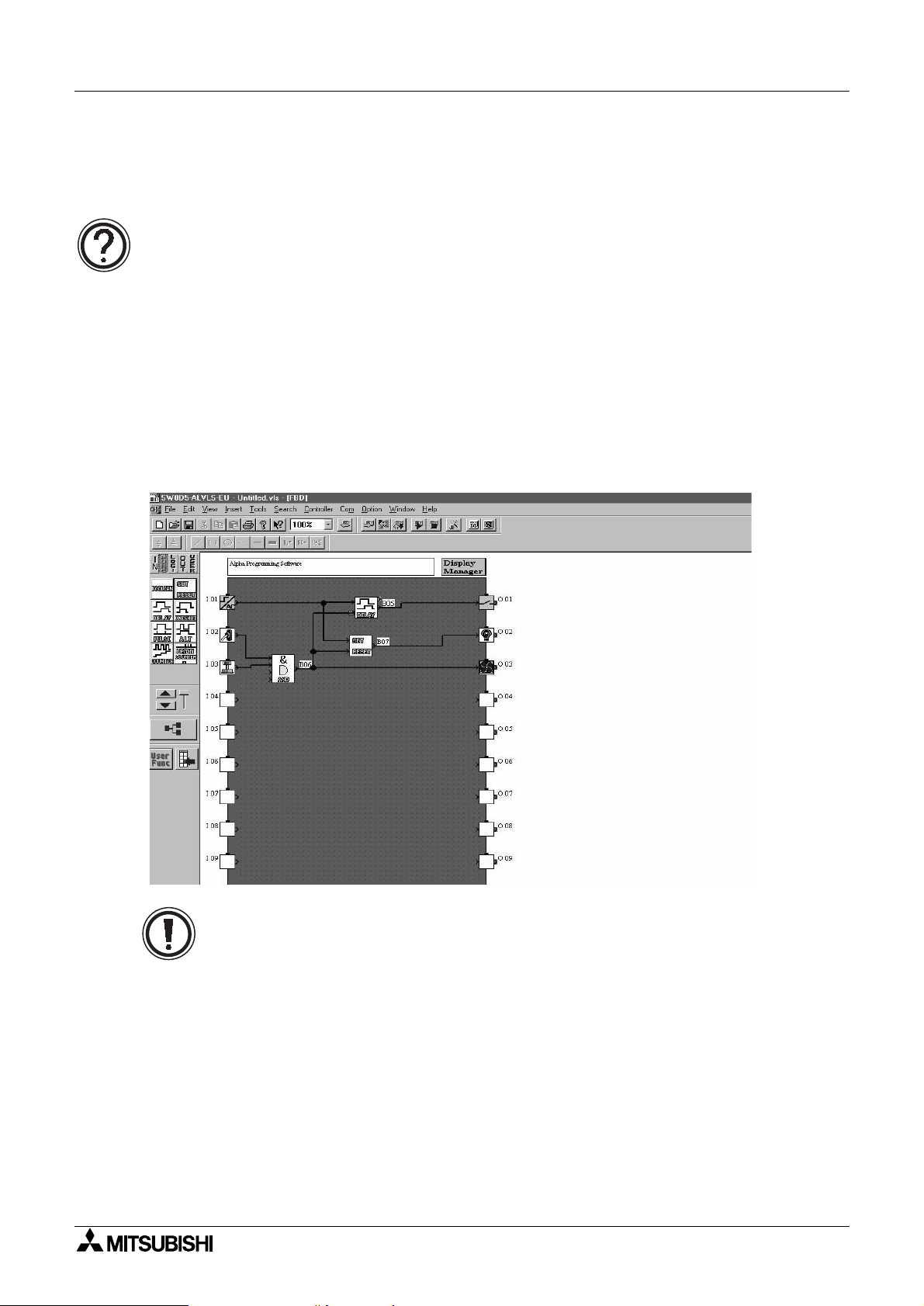
2.2.2 AL-PCS/WIN-E Programming Software Ver 2.00 and upwards
This windows based software allows the user to drag and drop the desired Function Block
icons onto the FBD base and construct a program. The program is downloaded to the
controller via the AL-232CAB cable. The visual on-screen connections make the software easy
to grasp for beginners and experienced users alike. The AL-PCS/WIN-E Programming
Software is fully explained in the
Figure 2.1: AL-PCS/WIN-E Programming Software Ver 2.00 and upwards
Software Manual (JY992D74001).
α
α
2
Note: Do not simultaneously program the
programming keys and AL-PCS/WIN-E Ver 2.00 methods as this may result in
unexpected operation and possibly cause harm.
2 Series Controller from the direct
α
2 - 5

α
2 Simple Application Controllers
Function Block Programming 2
MEMO
2 - 6

α
2 Simple Application Controllers
3. System Menu
3.1 Menu Options Instructions
There are Systems Menus to help guide the user through the options available in the α2. The
TopMenu has a Run Mode that is accessed while the
accessed when the
The Edit Menu and the Function Block Edit Menu can be accessed when in either ProgEdit or
Monitor. These menus can be used to create and/or change programs steps or values.
Use the “OK” key to enter a programming option or to enter data into memory.
Set all the data on the screen before using the “OK” key to write the data to the system
memory. If there are multiple data screens in an option, enter the required data and accept
each screen with the “OK” key.
The “ESC” key will move the screen back to a higher menu option. It will cancel any data input
that has not been accepted with the “OK” key.
2 is idle.
α
System Menu 3
2 is in operation or a Stop Mode that is
α
Note:
Use the “ESC” key to exit the option to the higher menu; at times, it will be necessary to press
the “ESC” key a number of times to move through multiple programming layers.
3 - 1
α
2 Simple Application Controllers
3.2 The Stop Mode
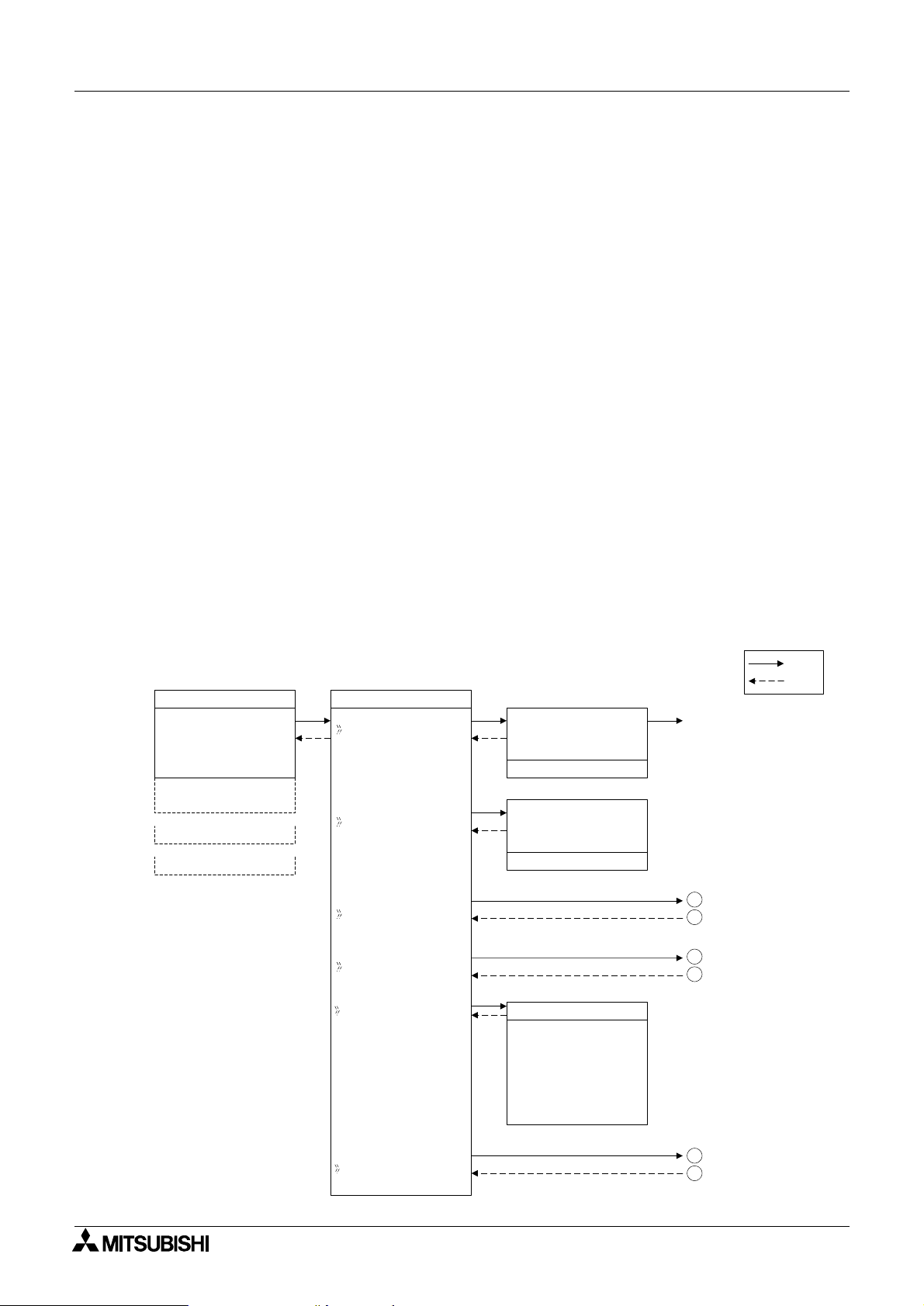
3.2.1 Top Menu
When the α2 is first turned On, the Input/Output Image Table will appear. Press the “OK” and
“ESC” keys simultaneously to move to the TopMenu.
(If the TopMenu cannot be accessed the Menu Key has been set to “Not Use”),
Run:
•
Places the controller in Run mode.
•Setup TS:
Provides a simple method to edit Time Switches from the Top Menu (only selectable if a
TSm function block has been chosen.)
ProgEdit:
•
Allows program editing/creation on the display using the front panel keys. The current
memory will be overwritten as changes are made to the program. Programs can be saved
on an AL2-EEPROM-2 memory cassette or in the AL-PCS/WIN-E software Version 2.0 or
above.
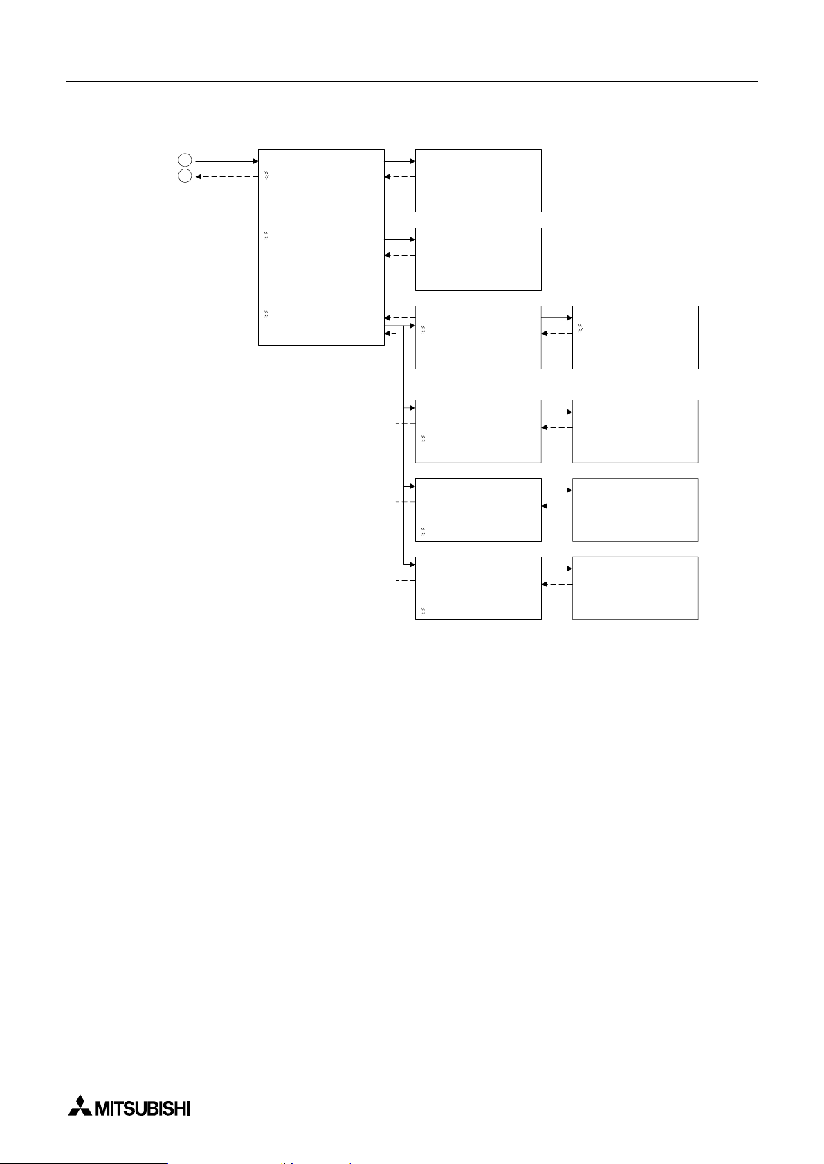
ClockSet:
•
Set the Real Time Clock or input a daily clock adjustment. The RadioClock function is also
available here.
LANGUAGE:
•
Choose from 6 onscreen languages: English, German, French, Italian, Spanish, or
Swedish.
Others...
•
System Menu 3
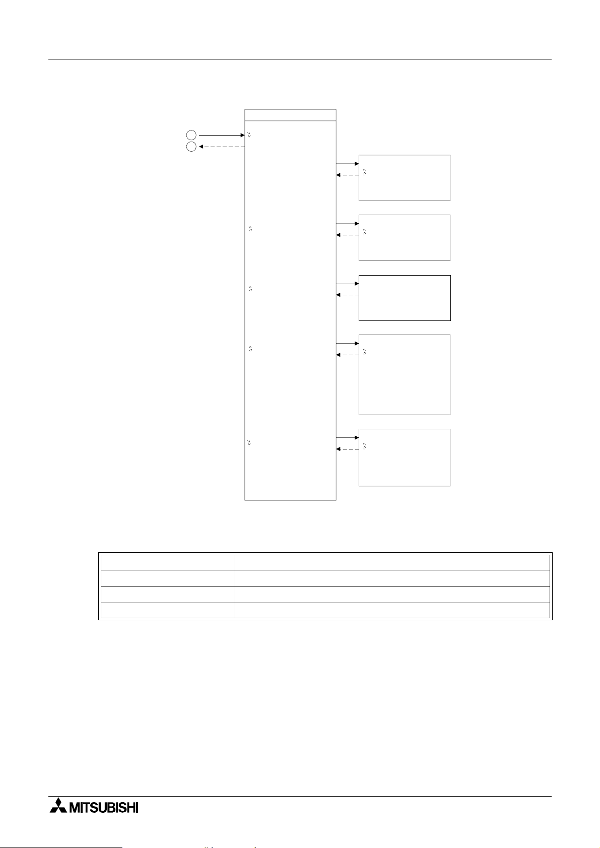
Figure 3.1: TopMenu in Stop Mode operation
TopMenu
10 : 19 Fr i
I:
•2••5 • •9
•1••••5
O:1• •4 • •8•
E:1• •4
A: •23
EI : • •41
EO : 23 ••
•
Run
Se t upTS
ProgEdi t
ClockSet
LANGUAGE
Run / S t op
OK o r ESC
Se t up
LANGUAGE
Eng l i sh
Ge r man
French
Italian
Spani sh
Sw d i sh
Stop
NoDa t a
e
→
Run
ST
Run Mode
1
2
9
1
0
OK
ESC
Other s
3
4
3 - 2
α
2 Simple Application Controllers
Figure 3.2: ClockSet Menu in Stop Mode Operation
System Menu 3
9
0
1
lockset
C
locksetC
e
Co r r c t
Rad i o C l o
ck Rad i o Clock
Clockse
dd/mm/yyyy
29 / 6 / 2003
Co r r ec t
Rad i o C l oc k
Rad i o C l o c k
Rad i o C l o c k
I npu t
Time Di f fer
Rad i o C l o c k
Rad i o C l o c k
I npu t
Time Di f fer
t
7:59 Sun
0.00s/d
Rad i o C l o c k
No t Us e
DCF 7 7
Rad i o C l o c k
I npu t
I01
Rad i o C l o c k
Time Di f fer
0.0
hrs
Rad i o C l o c k
I npu t
Time Di f fer
Manua l
Manua l
Stop Act
OK o r ESC
.
3 - 3

α
2 Simple Application Controllers
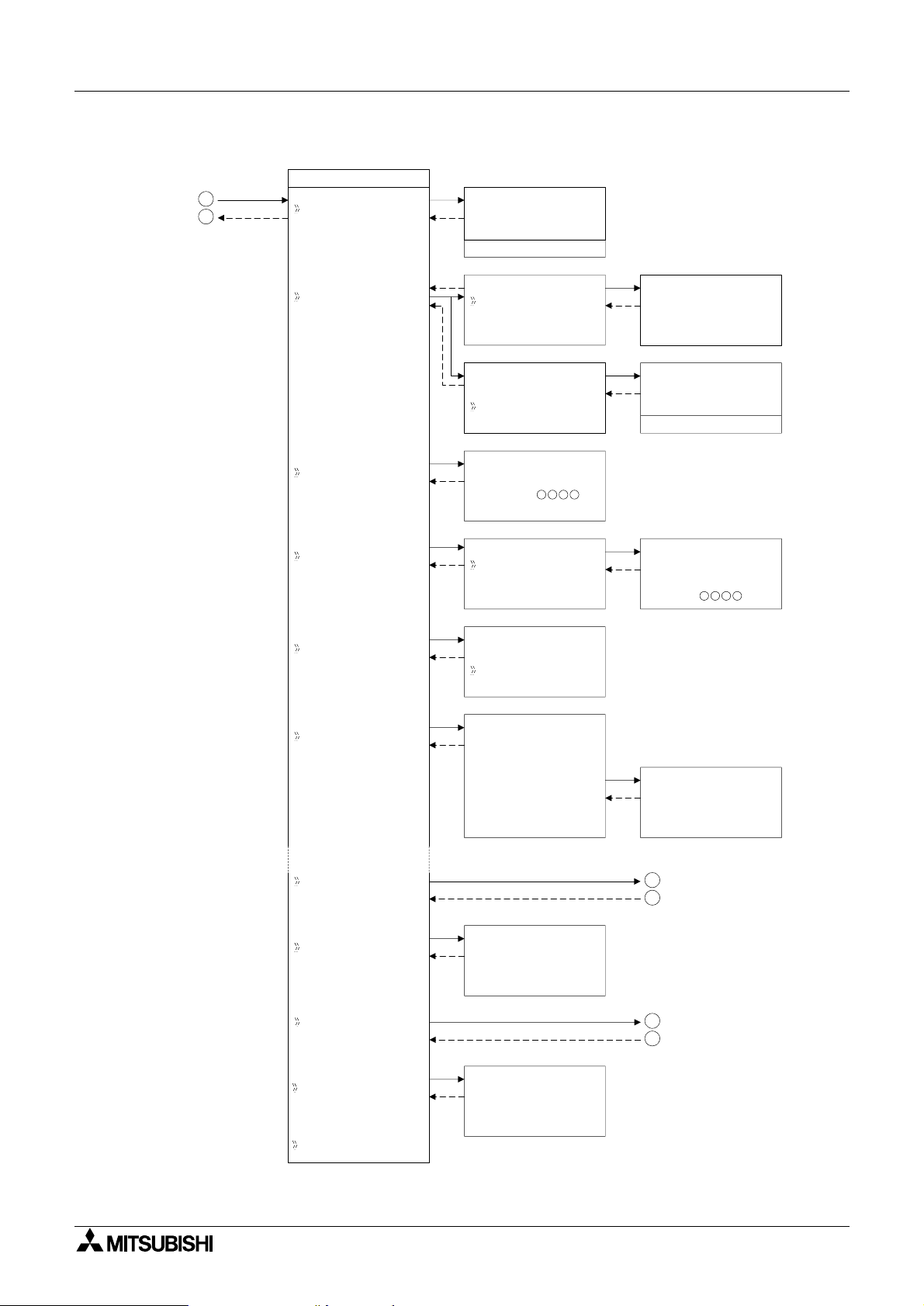
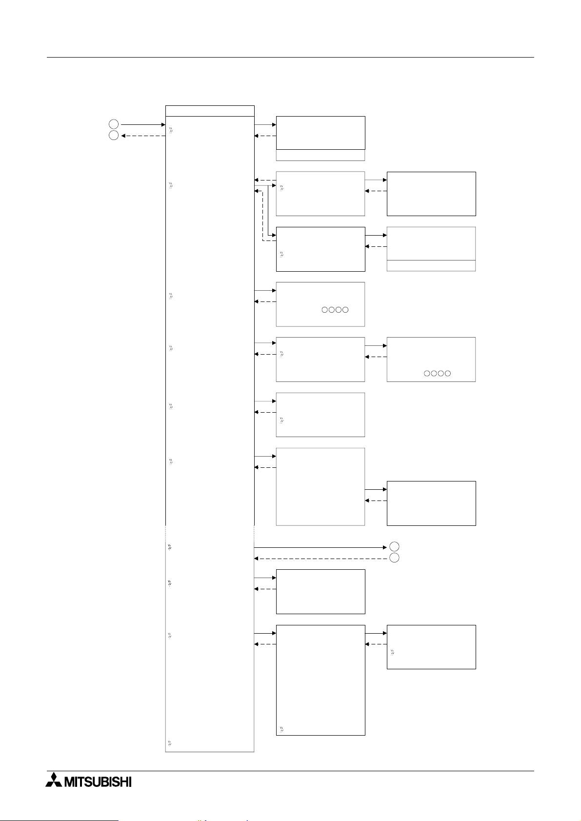
3.2.2 The “Others...
Version:
•
Displays CPU Version of the
• Scan Time:
Monitor the Current, Maximum, or Minimum program scan times. Upon controller reset
current, Maximum and Minimum values for scan times are reset to 0.
Password:
•
Restrict entry to the ProgEdit and Monitor mode with a four digit password.
• DispPass:
Set up to three Passwords for Display function blocks.
Menu Key:
•
Two settings are possible, “Not Use” or “OK + ESC”. “Not Use” is designed so that
unauthorized people cannot access the
setting is selected, simultaneously depress the “OK” and the “ESC” keys to access the Top
Menu.
Summertime:
•
Choose the preferred daylight savings time: Cancel, Manual On, Date Type, UK type, US
type, or EU type.
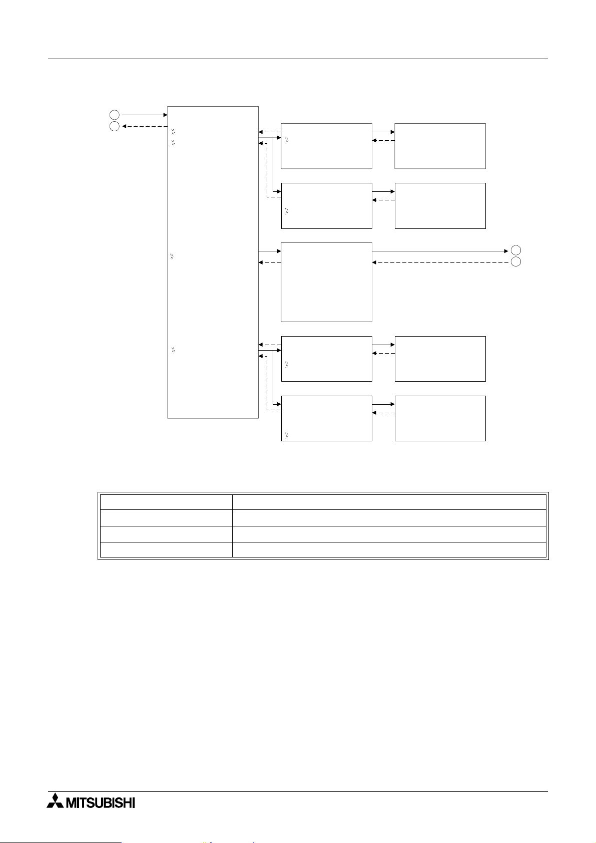
Serial Com:
•
Choose the type of communication to be used for the right hand side serial communication
port - Not Use, Modem, GSM or Other Com.
Light Time:
•
Set the backlight off delay time.
• Analog In:
Indicates the current modes (Normal, TC pr PT100) of the Analog inputs and the menu
item for changing the temperature scale (°C or °F) that the controller displays. Also
contains the menu items for calibration and offset adjust.
ProgClear:
•
Completely clears the system memory including Password protected programs. Only the
active memory is cleared, i.e. if a memory cassette is installed, the memory cassette
program will be erased but the controller memory will be retained.
ProgTran. (only appears if a cassette is installed):
•
Verify,
the
Cassette " (the cassette writes to the α2), Cassette #(the cassette reads from
2), and ProtectSW are the options available.
α
2 Series Controller.
α
2 Top Menu in Run mode. If the “OK + ESC” key
α
System Menu 3
3 - 4
α
2 Simple Application Controllers
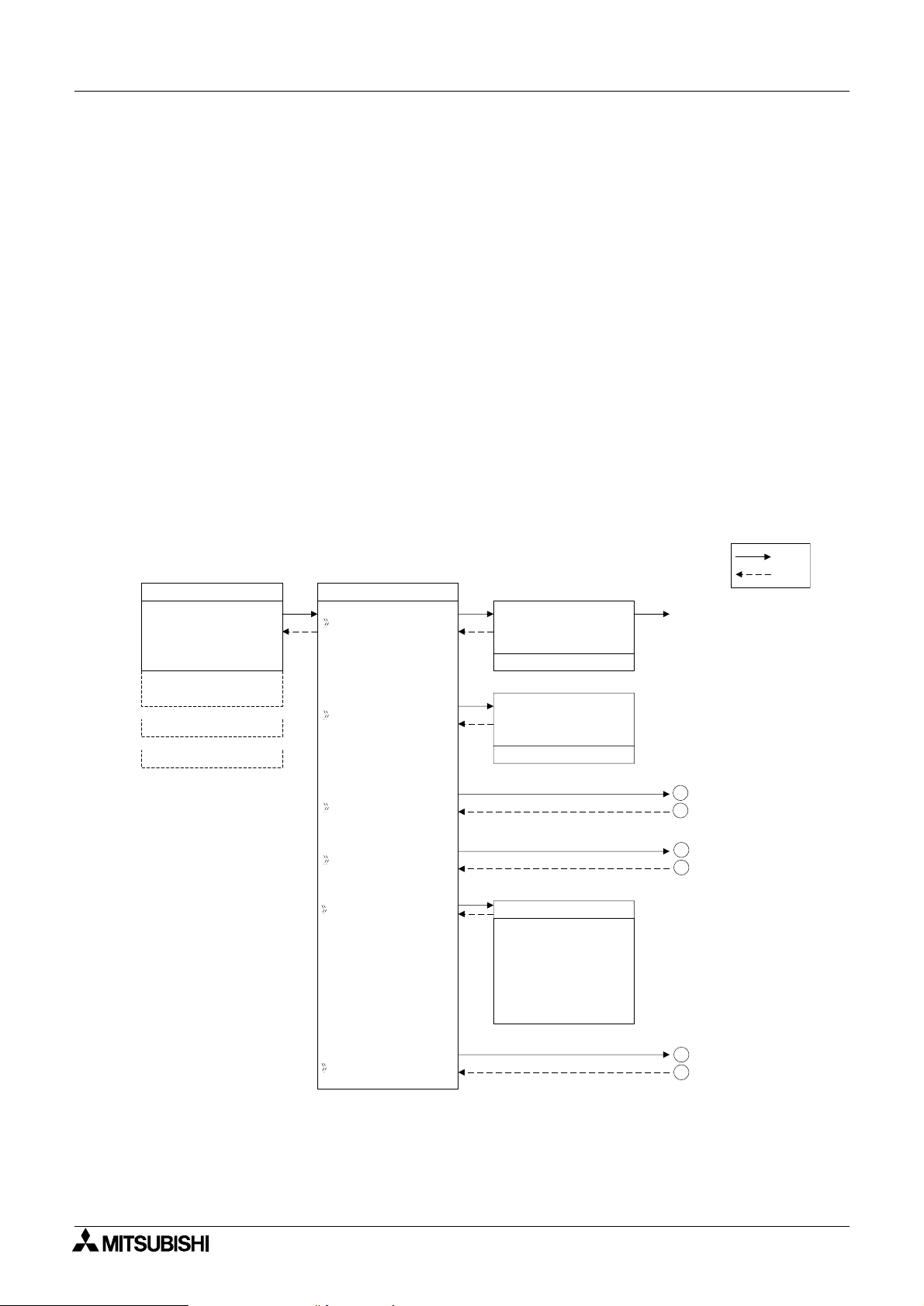
Figure 3.2: Others Menu in Stop Mode operation
3
4
System Menu 3
Others...
Ve r s i on
Ve r s i on
Ve r * . * *
Scan Tim
e
Pas swor d
DispPass
Menu Key
Summe r T ime
ScanT ime
Mo n i t o r
Res e t
ScanT ime
Mo n i t o r
Res e t
Se t up
Passwo r d
Di spPass
Leve l 1
Leve l 2
Leve l 3
MenuKey
No
Use
ON+
ESC
Key
Summe rT i me
Canc e l
Manua lOn
Da t aType
UK T y p e
US T y p e
EU T y p e
ScanT ime
Cu r . 0ms
Ma x .
Mi n
12ms
0ms
Res e t
ScanT ime
OK o r ESC
Se t up
Di spPass
Leve l 1
Summe r T i me
31 / 03
~30 / 10
+60mi n
Se r i a l Com
Light Time
Ana l og I n
Progc l ea r
ProgTr an
Se t up
Light Time
2m
Program
Clear
OK o r ESC
5
6
11
1
2
3 - 5
α
2 Simple Application Controllers
Figure 3.3: Serial Com in Stop Mode operation
System Menu 3
5
6
Se r i a l Com
No t Us e
Mo d em
GSM
OtherCom
ModemIn i t
Command
De l y T i me
a
ModemIn i t
Command
De l y T i mea
GSM
Comf o rma t
GSM I n i t
M
GS R emo t e
I
P NCode
Se t SMS
GSMStatus
OtherCom OtherCom
Comf o rma t *
Stat ionNo
L i nkBl ock
OtherCom
Comf o rma t *
Stat ionNo
L i nkBl ock
ModemIn i t 01
Command
[]
yz{ | } ! "#$
ModemIn i t
De l yT i mea
0s
Stat i onNo
No . 0
OtherCom
L i nkBl ock
0.
7
8
Figure 3.4: Communication Format in Stop Mode Operation
* Comformat
Datalength (bit) 8, 7
Parity None, Odd, Even
Stopbit (bit) 1, 2
Baudrate (bps) 300, 600, 1200, 2400, 4800, 9600, 19200
3 - 6
α
2 Simple Application Controllers
Figure 3.5: GSM Menu in Stop Mode operation
System Menu 3
GSM
7
8
Comf o rma t *
GSM I n i t
M
GS R emo t e
I
P NCode
Se t SMS
GSM I n i t
Commnd
De l a yT i me
M
GS R emo t e
Fo r b i t
Pe rmi t
PINCode
Se t up
[****]
Se t SMS
SMSC1
SMSC2
DA1
DA2
DA3
VP
GSMStatus
GSMStatus
Status
CMEE r r o r
CMSE r r o r
SigSeing
Figure 3.6: Communication Format in Stop Mode operation
* Comformat
Datalength (bit) 8, 7
Parity None, Odd, Even
Stopbit (bit) 1, 2
Baudrate (bps) 300, 600, 1200, 2400, 4800, 9600, 19200
3 - 7

α
2 Simple Application Controllers
Figure *.*: Analog Inputs Setup Menu.
System Menu 3
11
2
1
na l og nI
A
01I
T
I02: C
I03:P 100
Temp . ca lSe
T
I01
Mode
I02
Mode
Ca l i b r a t e
Of f se Fi net
I03
Mode
Ca l i b r a t e
Of f se Fi net
I03
Mode
Ca l i b r a t e
Of f se Fi net
Ana
log In
Temp
Ce l c i u s
Fah r e he i tn
.calSe
I01
No rma l
TC
PT100
I02
Ca l i b r a t e
-50°C
450°C
I03
Ca l i b r a t e
-50°C
200°C
I03
Of f se Fi net
0.0°C
3 - 8
α
2 Simple Application Controllers
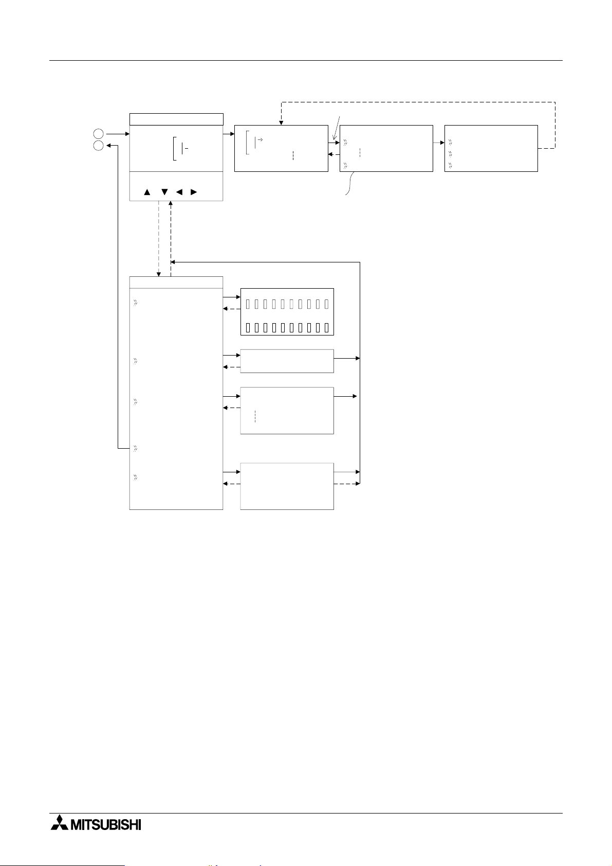
System Menu 3
Pr ogr amScreen
Adding Function Blocks
1
2
01
In
01
Add FB
O 01
Connect EO 04
(OK, ESC, +, -,
, , , )
(+) or (-) Skips to
the next topic
FBSe l e c t
AND
De l a yedA
FBPa r ame
Se t
ChangeN*2o
L
*1
Function Block Specific
*2
Changes Function Block Number
*3
Deletes Function Block from
De l e t eFB
FBD
upFB
ter
*1
*3
Edi tMenu
Block 0FB
ProgSi ze
Memo r y 0%
Jump
Jump
MIOKEANEIEOB
FBSe l e c t
NewFB
AND
Ex i t
Mn emo n i c
De l a yedA
M0 1 -
L
3 - 9
α
2 Simple Application Controllers
3.3 The Run Mode Top Menu
When the α2 program is running, the LCD defaults to the Image Table screen. According to
the Menu Key setting, proceed to the Stop Mode of the Top Menu by using the “OK” and the
“ESC” keys or reset the controller by powering down.
•Stop:
Takes the
•Setup TS:
Provides a simple method to edit Time Switches from the Top Menu.
Monitor:
•
Monitor the program settings while in the Run mode and perform limited editing to FB
parameters. The existing programming steps cannot be modified.
• ClockSet:
Set the Real Time Clock, input a daily clock adjustment or set the RadioClock function.
• LANGUAGE:
Choose the on-screen language from English, German, French, Italian, Spanish, or
Swedish.
•Others
Figure 3.8: TopMenu in Run Mode Operation
out of Run mode.
α
2
System Menu 3
10 : 19 Fr i
I : •2• •5 • •9
•1••••5
O:1• •4 • •8•
E:1• •4
A: •23
EI : • •41
EO : 23 ••
•
TopMenu
Stop
Se t upTS
Mo n i t o r
ClockSet
LANGUAGE
Run / S t op
→
Stop
Run
OK o r ESC
Se t up
LANGUAGE
Eng l i sh
Ge r man
French
Italian
Spani sh
Sw d i sh
TS
NoDa t a
e
Stop Mode
1
2
9
1
0
OK
ESC
Others
3
4
3 - 10
α
2 Simple Application Controllers
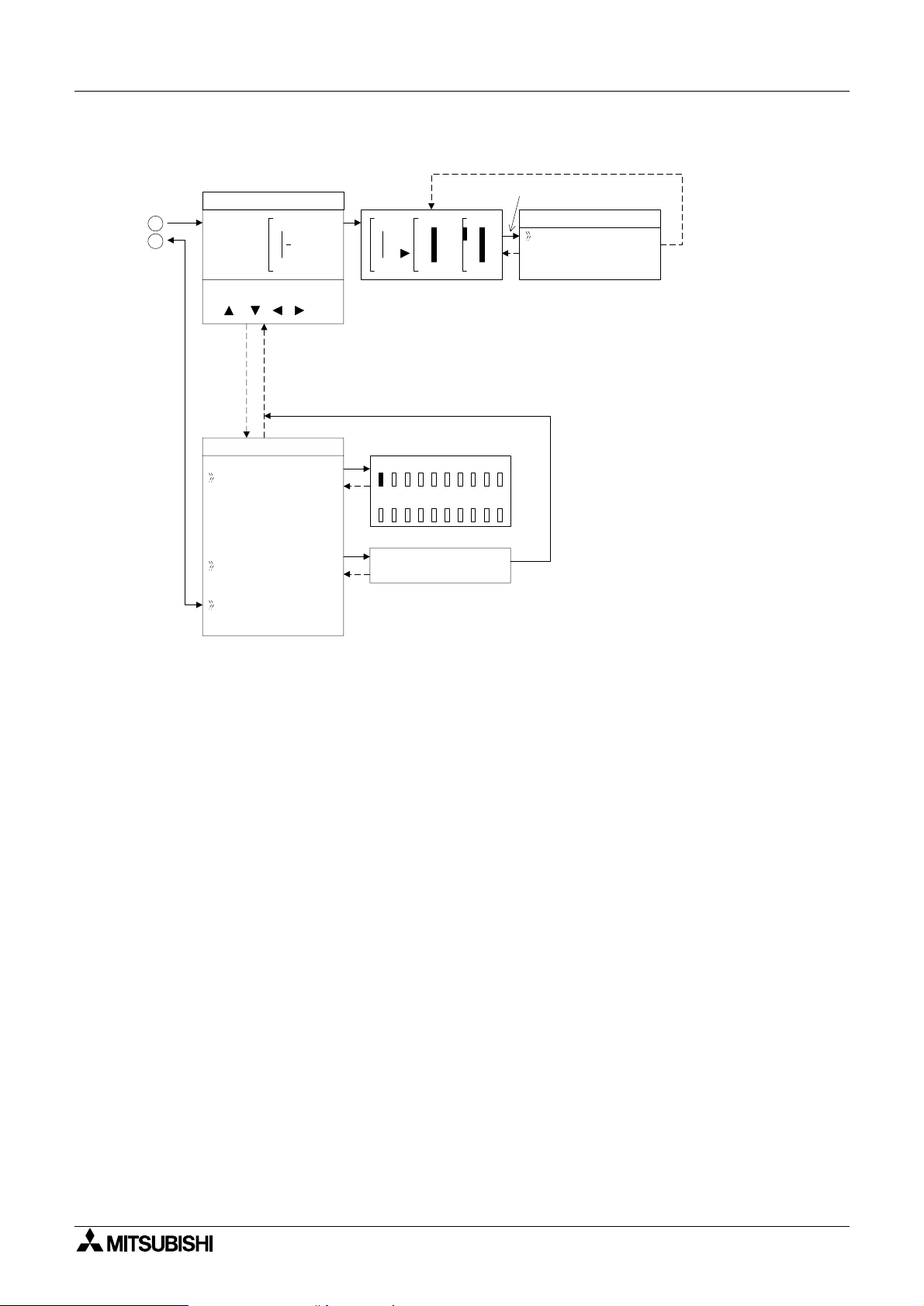
Figure 3.14: Monitor Screen in Run Mode.
System Menu 3
Mon i t o r S c r een
1
2
(OK, ESC, +, -,
, , , )
Ed i tMenu
ProgSi ze
Jump
Ex i t
01
B002
B003
In
Black 4FB
Memo r y 1%
MIOKEANEIEOB
01
=S
In
Jump
003
P- I
RSR
Settings for Function Blocks
02
Out
FBSe t t i n
-
Se t
*1
Individual for each Function Block.
g
up
3 - 11
α
2 Simple Application Controllers
Figure 3.9: Others Menu in Run Mode operation
Others...
3
4
System Menu 3
Ve r s i on
Ve r s i on
Ve r * . * *
Scan T i me
Pas swor d
DispPass
Menu Key
Summe r T ime
ScanT ime
Mo n i t o r
Res e t
ScanT ime
Mo n i t o r
Res e t
Se t up
Passwo r d
Di spPass
Leve l 1
Leve l 2
Leve l 3
MenuKey
No
Use
ON+
ESC
Key
Summe rT i me
Canc e l
Manua lOn
Da t aType
UK T y p e
US T y p e
EU T y p e
ScanT ime
Cu r . 0ms
Ma x .
Mi n
Res e t
ScanT ime
OK o r ESC
Se t up
Di spPass
Leve l 1
Summe r T i me
31 / 03
12ms
0ms
~30 / 10
+60mi n
Se r i a l Com
Light Time
Ana l og I n
ProgTr an
Se t up
LightTime
2m
log In
Ana
I01
I02
I03
I04
I05
I06
I07
I08
Temp . ca lSe
5
6
Ana
log In
Temp
Ce l c i u s
Fah r e he i tn
.calSe
3 - 12
 Loading...