

Page 1
ENG
GER
FRE
ITL
α
2 Simple Application Controller
HARDWARE MANUAL
HARDWARE-HANDBUCH
MANUEL DU MATÉRIEL
MANUALE HARDWARE
MANUAL DE HARDWARE
ESP
SWE
MASKINVARUHANDBOK
Page 2

α
2 Simple Application Controllers
Foreword
• This manual contains text, diagrams and explanations which will guide the reader in the correct installation,
safe use and operation of the
use the unit.
α
2 series and should be read and understood before attempting to install or
• If in doubt at any stage of the installation of the
who is qualified and trained to the local and national standards. If in doubt about the operation or use of the
a series controller please consult the nearest Mitsubishi Electric distributor.
• This manual is subject to change without notice.
α
2 series always consult a professional electrical engineer
Page 3

2 Simple Application Controller
α
2 Simple Application Controller
α
Hardware Manual
ENG
Manual number: JY992D97301
Manual revision: B
Date: 06/2002
ENG-i
Page 4

2 Simple Application Controller
α
ENG-ii
Page 5

α
2 Simple Application Controller
FAX BAC K
Mitsubishi has a world wide reputation for its efforts in continually developing and pushing back
the frontiers of industrial automation. What is sometimes overlooked by the user is the care
and attention to detail that is taken with the documentation. However, to continue this process
of improvement, the comments of the Mitsubishi users are always welcomed. This page has
been designed for you, the reader, to fill in your comments and fax them back to us. We look
forward to hearing from you.
Fax numbers: Your name....................................................
Mitsubishi Electric.... .....................................................................
America (01) 847-478-2253 Your company ..............................................
Australia (02) 638-7072 .....................................................................
Germany (0 21 02) 4 86-11 20 Your location: ...............................................
Spain (0 34) 93 589-1579 .....................................................................
United Kingdom (01707) 278-695
ENG
Please tick the box of your choice
What condition did the manual arrive in?
Will you be using a folder to store the manual?
What do you think to the manual presentation?
Are the explanations understandable?
Which explanation was most difficult to understand: ..................................................................
....................................................................................................................................................
Are there any diagrams which are not clear?
If so,which:..................................................................................................................................
What do you think to the manual layout?
If there one thing you would like to see improved, what is it?.....................................................
....................................................................................................................................................
....................................................................................................................................................
Could you find the information you required easily using the index and/or the contents, if
possible please identify your experience: ...................................................................................
....................................................................................................................................................
....................................................................................................................................................
....................................................................................................................................................
....................................................................................................................................................
Good
Yes No
Tidy Unfriendly
Yes Not too bad Unusable
Yes No
Good
Minor damage
Not too bad
Unusable
Unhelpful
Do you have any comments in general about the Mitsubishi manuals?.....................................
....................................................................................................................................................
....................................................................................................................................................
....................................................................................................................................................
....................................................................................................................................................
Thank you for taking the time to fill out this questionnaire. We hope you found both the product
and this manual easy to use.
ENG-iii
Page 6

2 Simple Application Controller
α
ENG-iv
Page 7
2 Simple Application Controller
α
Guidelines for the Safety of the User and Protection of equipment
This manual provides information for the use of theα2 Series Controllers. The manual has
been written to be used by trained and competent personnel. The definition of such a person
or persons is as follows;
a) Any engineer who is responsible for the planning, design and construction of automatic
equipment using the product associated with this manual should be of a competent
nature, trained and qualified to the local and national standards required to fulfill that
role. These engineers should be fully aware of all aspects of safety with regards to
automated equipment.
b) Any commissioning or service engineer must be of a competent nature, trained and
qualified to the local and national standards required to fulfill that job. These engineers
should also be trained in the use and maintenance of the completed product. This
includes being completely familiar with all associated documentation for the said
product. All maintenance should be carried out in accordance with established safety
practices.
c) All operators of the completed equipment should be trained to use that product in a safe
and coordinated manner in compliance to established safety practices. The operators
should also be familiar with documentation which is connected with the actual operation
of the completed equipment.
ENG
Note :
NotesontheSymbolsUsedinthisManual
At various times through out this manual certain symbols will be used to highlight points of
information which are intended to ensure the users personal safety and protect the integrity of
equipment. Whenever any of the following symbols are encountered its associated note must
be read and understood. Each of the symbols used will now be listed with a brief description of
its meaning.
Hardware Warnings
Software Warnings
The term ‘completed equipment’ refers to a third party constructed device which
contains or uses the product associated with this manual.
1) Indicates that the identified danger
2) Indicates that the identified danger could
damage.
3) Indicates a point of further interest or further explanation.
4) Indicates special care must be taken when using this element of software.
WILL
cause physical and property damage.
POSSIBLY
cause physical and property
5) Indicates a special point which the user of the associate software element should
be aware of.
6) Indicates a point of interest or further explanation.
ENG-v
Page 8

2 Simple Application Controller
α
• Under no circumstances will Mitsubishi Electric be liable or responsible for any
consequential damage that may arise as a result of the installation or use of this equipment.
• All examples and diagrams shown in this manual are intended only as an aid to
understanding the text, not to guarantee operation. Mitsubishi Electric will accept no
responsibility for actual use of the product based on these illustrative examples.
• Owing to the very great variety in possible application of this equipment, you must satisfy
yourself as to its suitability for your specific application.
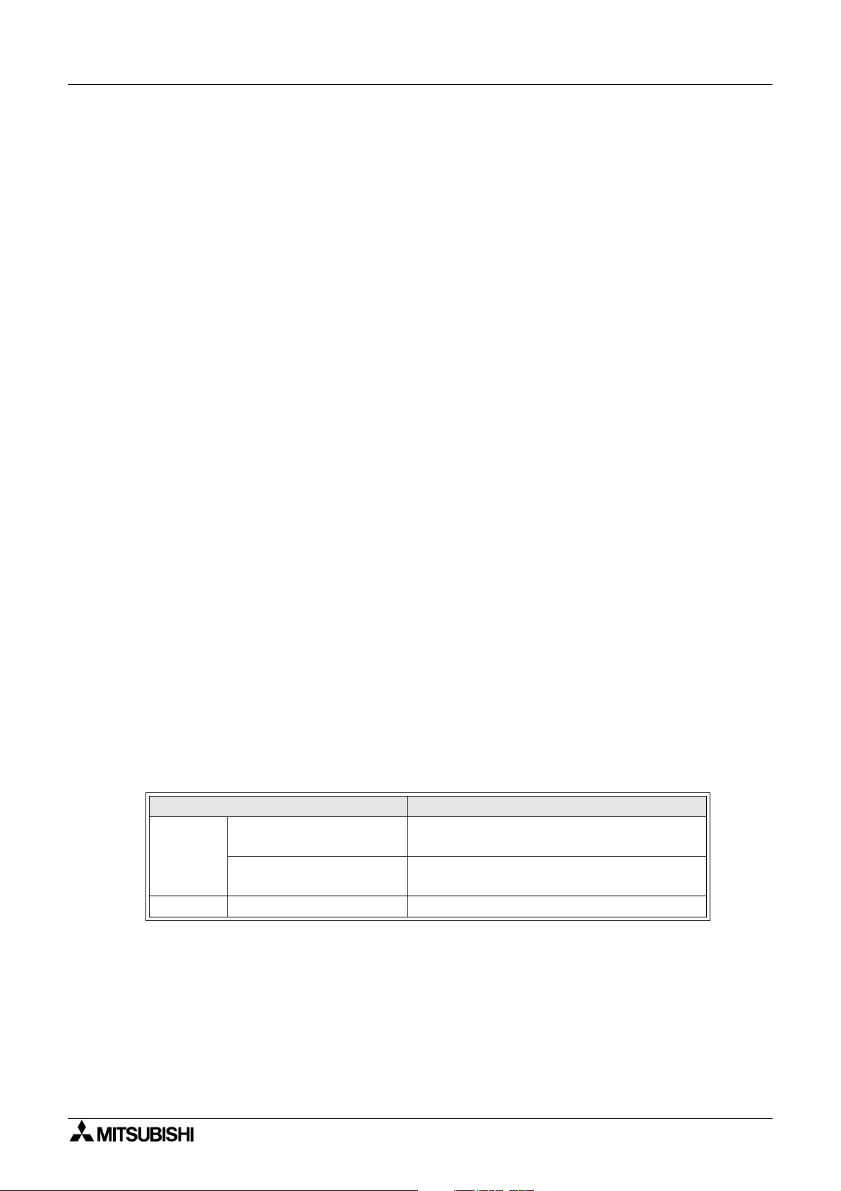
Further Information Manual Lists
Manual Name Manual No. Description
α
2 Hardware Manual
(This manual)
α2 Programming Manual
<English only>
JY992D97301
JY992D97101
This manual contains hardware explanations for
wiring, installation and specification for
Series controllers.
This manual contains instruction explanations for
α
the
2 Series controllers.
α2
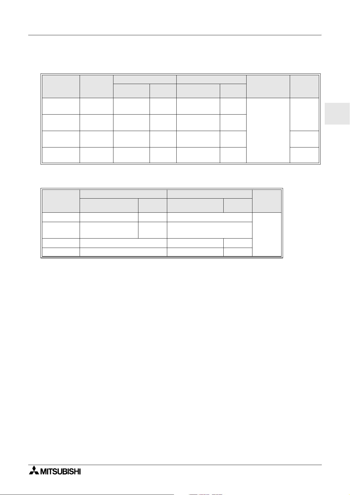
α
Software Manual
<English only>
α
2 Series Communication
User’s Manual
<English only>
α
2 Series Installation Manual
AL2-4EX, AL2-4EX-A2,
AL2-4EYR, AL2-4EYT
Installation Manual
AL2-EEPROM-2
Hardware Manual
AL-232CAB
Hardware Manual
AL2-GSM-CAB
Hardware Manual
AL-ASI-BD, AL2-ASI-BD
Hardware Manual
Refer to these manuals.
JY992D74001
JY992D97701
JY992D97501
JY992D97401
JY992D96801
JY992D76001
JY992D97201
JY992D81401
This manual contains explanations of operation
of AL-PCS/WIN-E Programming Software.
This manual contains explanations for the setup,
messaging, diagnostics, bit assignments, etc for
communications using the
This manual contains hardware explanations of
α
installation for
This manual contains hardware explanations of
installation for AL2-4EX, AL2-4EX-A2, AL24EYR and AL2-4EYT extension module.
This manual contains hardware explanations of
installation for AL2-EEPROM-2.
This manual contains hardware explanations of
installation for AL-232CAB.
This manual contains hardware explanations of
installation for AL2-GSM-CAB.
This manual contains hardware explanations of
wiring, installation and specification, etc. for ALASI-BD and AL2-ASI-BD.
2 Series controller.
α
2 series controller.
Refer to this manual if necessary.
Refer to the content of these manuals if necessary though it is included in
Manual.
α
2 Hardware
ENG-vi
Page 9

2 Simple Application Controllers
α
Table of Contents
Guidelines of Safety....................................................................ENG-v
1. Introduction......................................................................................ENG-1
1.1 Special Features of theα2 Series System.................................................... ENG-2
1.2 Available Models ........................................................................................... ENG-3
1.3 Dimensions and Each Part Name ................................................................. ENG-4
1.4 System Configuration .................................................................................... ENG-5
1.5 Applicable Programming Software ................................................................ ENG-5
2. Specifications ..................................................................................ENG-7
2.1 Power Supply Specification ........................................................................... ENG-7
2.2 Input Specification ........................................................................................ ENG-8
2.3 Output Specification .................................................................................... ENG-10
2.4 General Specification .................................................................................. ENG-11
ENG
3. Installation .....................................................................................ENG-13
3.1 Installation Mounting Notes ......................................................................... ENG-13
3.2 DIN RAIL Mounting of Main Unit ................................................................. ENG-14
3.2.1 Installation ......................................................................................................... ENG-14
3.2.2 Remove ............................................................................................................. ENG-14
3.3 Direct Mounting of Main Unit ....................................................................... ENG-15
3.4 Install Extension Module.............................................................................. ENG-15
4. Wiring ............................................................................................ENG-17
4.1 Installation Wiring Notes.............................................................................. ENG-17
4.2 Wire Size ..................................................................................................... ENG-18
4.3 Power Supply .............................................................................................. ENG-19
4.4 AC Power Supply and Input Wiring ............................................................. ENG-20
4.4.1 AC Power Supply and Input Wiring ................................................................... ENG-20
4.4.2 AL2-4EX-A2 Input Wiring .................................................................................. ENG-20
4.5 DC Power Supply and Input Wiring ............................................................. ENG-21
4.5.1 DC Power Supply and Source (“+” Common) Input Wiring Diagram ................ ENG-21
4.5.2 AL2-4EX Source (“+” Common) Input Wiring Diagram ..................................... ENG-21
4.5.3 DC Power Supply and Sink (“-” Common) Input Wiring Diagram...................... ENG-22
4.5.4 AL2-4EX Sink (“-” Common) Input Wiring Diagram........................................... ENG-22
4.6 Output Relay and Transistor Wiring ............................................................ ENG-23
4.6.1 Relay Output Wiring Diagram main unit (AC and/or DC) .................................. ENG-23
4.6.2 Relay Output Wiring Diagram AL2-4EYR (AC and/or DC) ................................ ENG-24
4.6.3 Transistor Output (Source or “+”CommonOnly) Wiring Diagram AL2-4EYT... ENG-25
5. Terminal Layout............................................................................ENG-27
6. AL2-EEPROM-2............................................................................ENG-29
6.1 Installation ................................................................................................... ENG-30
ENG-vii
Page 10

2 Simple Application Controllers
α
7. AL-232CAB ...................................................................................ENG-31
7.1 Introduction.................................................................................................. ENG-31
7.1.1 External Dimensions ......................................................................................... ENG-31
7.2 Connected to AL-232CAB cable.................................................................. ENG-32
8. AL2-GSM-CAB..............................................................................ENG-35
8.1 Introduction.................................................................................................. ENG-35
8.1.1 External Dimensions ......................................................................................... ENG-35
8.1.2 System Configuration with using AL2-GSM-CAB.............................................. ENG-36
8.2 Installation ................................................................................................... ENG-37
8.3 Remote Maintenace with a Modem ............................................................. ENG-39
8.3.1 Recommended Modems ................................................................................... ENG-39
8.3.2 RS-232C Straight Cable Between Modem and AL2-GSM-CAB........................ ENG-39
8.3.3 Modem Setting .................................................................................................. ENG-40
9. AL2-ASI-BD...................................................................................ENG-43
9.1 Introduction.................................................................................................. ENG-43
9.1.1 External Dimensions ......................................................................................... ENG-43
9.1.2 System Configuration ........................................................................................ ENG-44
9.2 Specifications .............................................................................................. ENG-44
9.3 Wiring & Installation..................................................................................... ENG-45
9.3.1 Installation ......................................................................................................... ENG-45
9.3.2 Wiring ................................................................................................................ ENG-46
9.4 Slave Address Setting & Diagnostics .......................................................... ENG-46
9.4.1 Setting Slave Address ....................................................................................... ENG-46
9.4.2 Applicable Error checks..................................................................................... ENG-46
10.Key, System Bit and Function Block Lists ....................................ENG-47
10.1 Key Lists ...................................................................................................... ENG-47
10.2 System Bit Lists ........................................................................................... ENG-48
10.2.1 System Bit Lists................................................................................................. ENG-48
10.2.2 Control Bit Lists ................................................................................................. ENG-48
10.3 Function Block Lists..................................................................................... ENG-49
11.Diagnostics...................................................................................ENG-53
11.1 Input Status Error ........................................................................................ ENG-54
11.2 Output Status Error...................................................................................... ENG-54
11.3 TOP MENU is not Displayed ....................................................................... ENG-55
11.4 Cannot enter Run Mode. ............................................................................. ENG-56
11.5 Incorrect Clock Data .................................................................................... ENG-56
11.6 The “?” appears on the Display ...................................................................ENG-56
11.7 Cannot Use an Operation Key..................................................................... ENG-57
11.8 Incorrect LCD display .................................................................................. ENG-58
11.9 Memory Cassette Is Not Working Correctly................................................. ENG-58
11.10Cannot Communicate with the AS-interface Master Module ...................... ENG-59
11.11Cannot Communicate with AL-PCS/WIN-E. ............................................... ENG-60
ENG-viii
Page 11

α
2 Simple Application Controllers
1. Introduction
Theα2 series can be easily used in all places where control is needed for the home, office, or
factory. The controller outputs cycle ON/OFF to control electrical equipment per the Function
Block program.
The explanation of the instructions and the operation of main unit can be found in
Programming Manual. An explanation of the AL-PCS/WIN-E programming software can be
found in the
Applications
α
The
- Automation of lights, air-conditioning, or watering systems
- The opening and shutting of gates
- Easy security systems
- Domestic animal and pet food distribution systems
- Control of stockyards and greenhouses
α
Series Software Manual.
2 series is designed to be used in automatic applications including those listed below.
Introduction 1
α
2
ENG
α
However, the
a Mitsubishi distributor for more information.
- Applications where high reliabilities such as nuclear power control, railway facilities,
airline facilities, vehicles, combustion equipment, and medical equipment are required.
- Applications in life critical situations.
2seriesisnotdesignedtobeusedinthefollowingapplications.Pleasecontact
ENG-1
Page 12
α
2 Simple Application Controllers
1.1 Special Features of theα2SeriesSystem
1) Display message and Function Block data
α
The
message. It can display the following contents by the using display function block. The
value of displayed timers and counters can be changed in the RUN mode.
- Total characters on LCD display: 12 characters×4 lines
- Display Items: Message, value (current or set) of timer and counter, analog values, etc
2) The programming in the personal computer is fast and easy
The programming software AL-PCS/WIN-E for Windows can make and save programs.
The programming can be done using a pictorial method in which lines are used to connect
function blocks on a programming screen.
Direct programming using the
3) LCD image send via GSM modem
The
can monitor application status by accessing the diagnostic message sent as an E-mail via
GSM modem
2 series can display the state of operation and the alarm on the LCD display as a
α
2 controller front panel keys is also available.
α
2 series is able to send the LCD image as an E-mail using a GSM modem. The user
Introduction 1
4) Supports computer link using dedicated protocol
α
The
software using computer link (dedicated protocol) can change schedule data, parameters
within Function Blocks and provide condition monitoring of the application.
5) Enhancement of clock function
The weekly timer and the calendar timer function have many switches that can be set and
provide powerful time dependant control capabilities.
6) Analog input, 0 - 10V/0 - 500:
The DC input for the
7) High speed counter, Max. 1kHz
The
8) High current output capability
2 series supports computer link (dedicated protocol). User-specific application
α
2 series can accept of 0 - 10V signals with a resolution of 0 - 500.
α
2 series has high speed counters (Max. 2 points) when using AL2-4EX (EI1, EI2).
Table 1.1: High Current Output Capability
Output Type Capability
AL2-14MR-*: O01-06
Relay
Transistor AL2-4EYT: EO1-EO41A/Point
AL2-24MR-*: O01-04
AL2-24MR-*: O05-09
AL2-4EYR: EO1-EO4
8A/Common
2A/Point (4A/Common)
9) Built-in EEPROM
The built in EEPROM eliminates the need for battery backed data.
10)Supports 6 languages:
α
The
Swedish). The displayed language can be selected in the TOP MENU.
2 series supports 6 languages (English, German, French, Italian, Spanish, and
ENG-2
Page 13
α
2 Simple Application Controllers
1.2 Available Models
Table 1.2:Main Units
Model
AL2-14MR-A
AL2-14MR-D 24V DC
AL2-24MR-A
AL2-24MR-D 24V DC
Power
Supply
100 - 240V
AC~
100 - 240V
AC~
100 - 240V
Sink/Source
100 - 240V
Sink/Source
*1 Without extension modules.
Table 1.3:Extension Modules
Input Output MASS
Model
AL2-4EX-A2 220 - 240V AC~ 4
AL2-4EX
AL2-4EYR RELAY 4
AL2-4EYT TRANSISTOR4
Type Number Type Number
24V DC, Sink/
Source
Input Output
Type Number Type Number
AC~
24V DC
AC~
24V DC
8RELAY6
8RELAY6
15 RELAY 9
15 RELAY 9
4
Dimensions
mm (inches)
124.6 x 90 x 52
(4.91 x 3.54
x 2.05)
(Weight)
kg (lbs)
0.05
(0.11)
Introduction 1
MASS
(Weight)
kg (lbs)
*1
0.30
(0.66)
*1
0.35
(0.77)
*1
0.30
(0.66)
ENG
ENG-3
Page 14
α
2 Simple Application Controllers
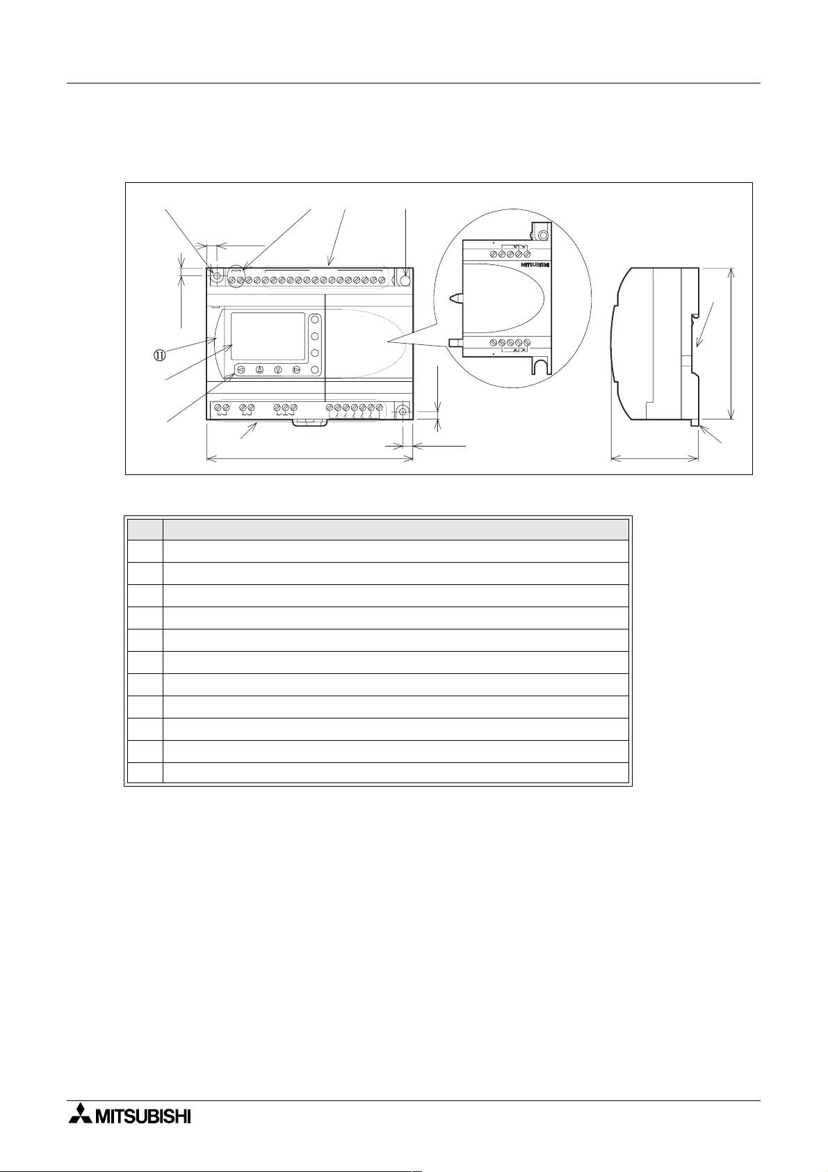
1.3 Dimensions and Each Part Name
Figure 1.1: Each Part Name
Introduction 1
6(0.24")
+-
POW ER
24V DC
4(0.16")
AL2-24MR -D
OUT1
OUT2 OUT4
D C IN P U T
ESC
+
-
OK
RELAY
OUTPUT
OUT3
124.6(4.91")
65
7
OUT
+-E01E02
151413121110987654321(B )(A )
9
8
4(0.16")
+E03-E04
6(0.24")
Table 1.4: Each Part Name
Ref. Item Description
1 Mounting hole, φ4.2 mm
2 Power terminals
3 Input terminals
4 Mounting screw for the extension cover or extension module
5 Extension cover or extension module
6 Groove for DIN rail mounting (Width of DIN rail 35mm <DIN EN 50022>)
7 DIN-RAIL mounting clips
8 Output terminals
9 Operation keys
10 Liquid crystal display
11 Programming port cover
52(2.05")
90(3.54")
ENG-4
Page 15
α
2 Simple Application Controllers
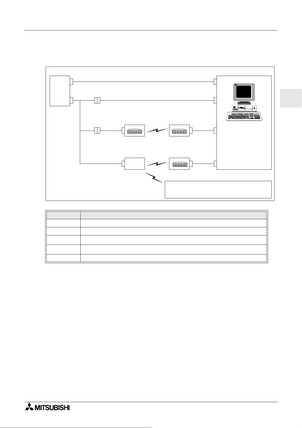
1.4 System Configuration
Figure 1.2: System Configuration
Standard Connection to the Programming Softoware
α
2
Series
Introduction 1
UsingDedicatedProtocol
ENG
Remote Maintenance (via Telephone Line)
Normal Modem Normal Modem
Remote Maintenance, e-Mail (via GSM)
Normal Modem
GSM
Modem
Personal computer
- Programming Software
(AL-PCS/WIN-E)
- Dedicated protocol
- e-Mail application
Sending SMS Message
Table 1.5: System Configuration
Item Using Cable
1 AL-232CAB
2AL2-GSM-CAB
3
4
RS-232C cross cable
RS-232C straight cable for the modem
*1
5 RS-232C straight cable for the modem (specified by Modem manufacture)
*1 Further information can be found in chapter 8.
1.5 Applicable Programming Software
Theα2 series is supported by the programming software (AL-PCS/WIN-E) V2.00 or
later. Versions lower than V2.00, do not communicate with the
Cellular Phone
(Supporting SMS message)
*1
α
2series.
ENG-5
Page 16

α
2 Simple Application Controllers
Introduction 1
MEMO
ENG-6
Page 17
α
2 Simple Application Controllers
2. Specifications
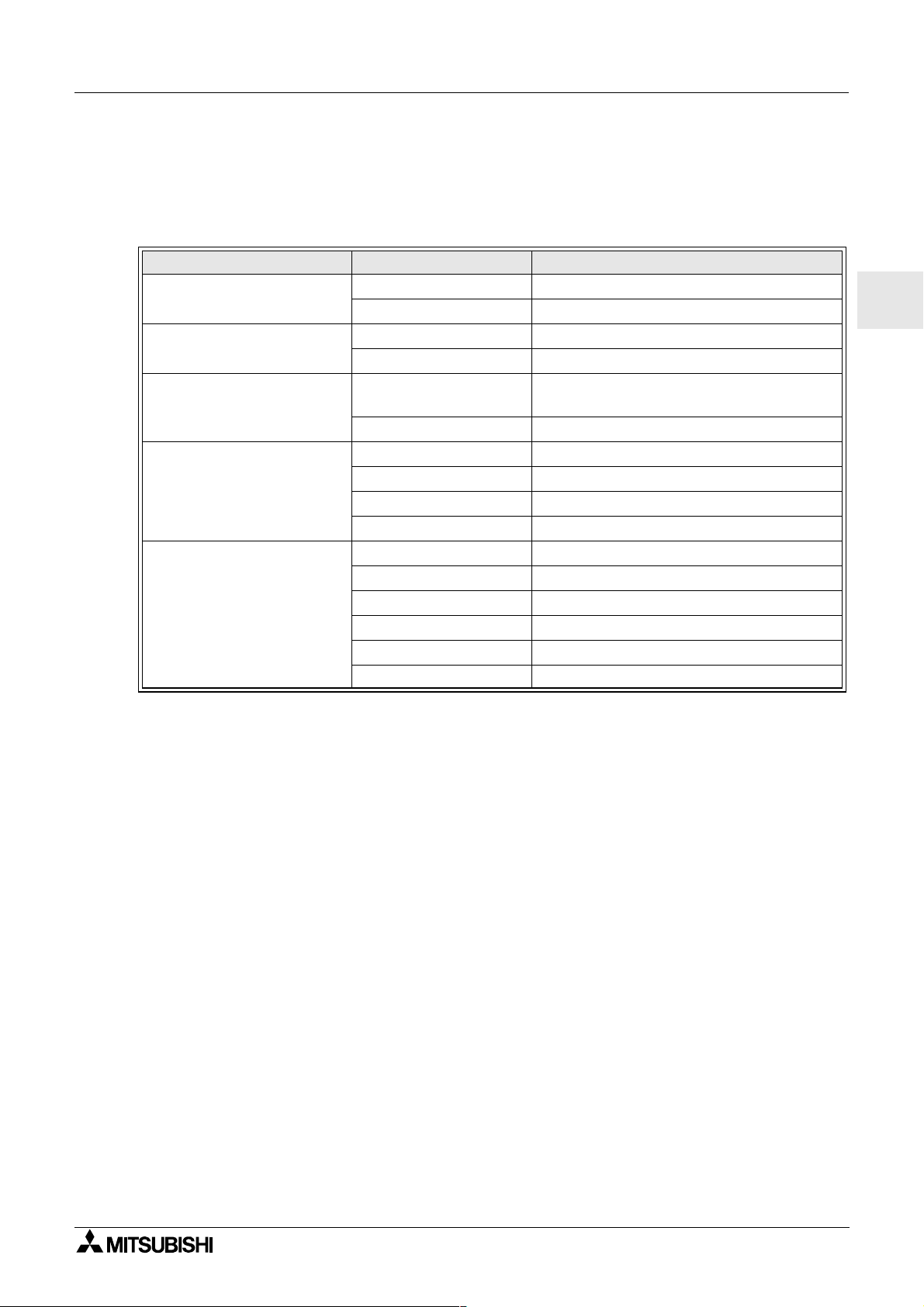
2.1 Power Supply Specification
Table 2.1: Power Supply Specifications
Description Code Specification
Power Supply
Maximum Momentary Power
Failure
In-rush Current
Maximum Power
Consumption
Typical Power Consumption
(without Special Connection
Modules)
AL2-***-A 100 - 240V AC~, +10% -15%, 50/60 Hz
AL2-***-D 24V DC, +20% -15%
AL2-***-A 10ms
AL2-***-D 5ms
AL2-***-A,
240V AC~ (120V AC~)
AL2-***-D, 24V DC ≤ 7.0 A
AL2-14MR-A, 264V AC~ 5.5 W
AL2-14MR-D, 28.8V DC 7.5 W
AL2-24MR-A, 264V AC~ 7.0 W
AL2-24MR-D, 28.8V DC 9.0 W
AL2-14MR-A, 240V AC~ I/O all On-4.5W;I/O all Off - 2.0 W
AL2-14MR-A, 120V AC~ I/O all On-3.5W;I/O all Off - 1.5 W
AL2-14MR-D, 24V DC I/O all On-4.0W;I/O all Off - 1.0 W
AL2-24MR-A, 240V AC~ I/O all On-5.5W;I/O all Off - 2.5 W
AL2-24MR-A, 120V AC~ I/O all On-4.5W;I/O all Off - 2.0 W
AL2-24MR-D, 24V DC I/O all On-5.0W;I/O all Off - 1.0 W
Specifications 2
ENG
≤ 6.5 A (3.5 A)
ENG-7
Page 18
α
2 Simple Application Controllers
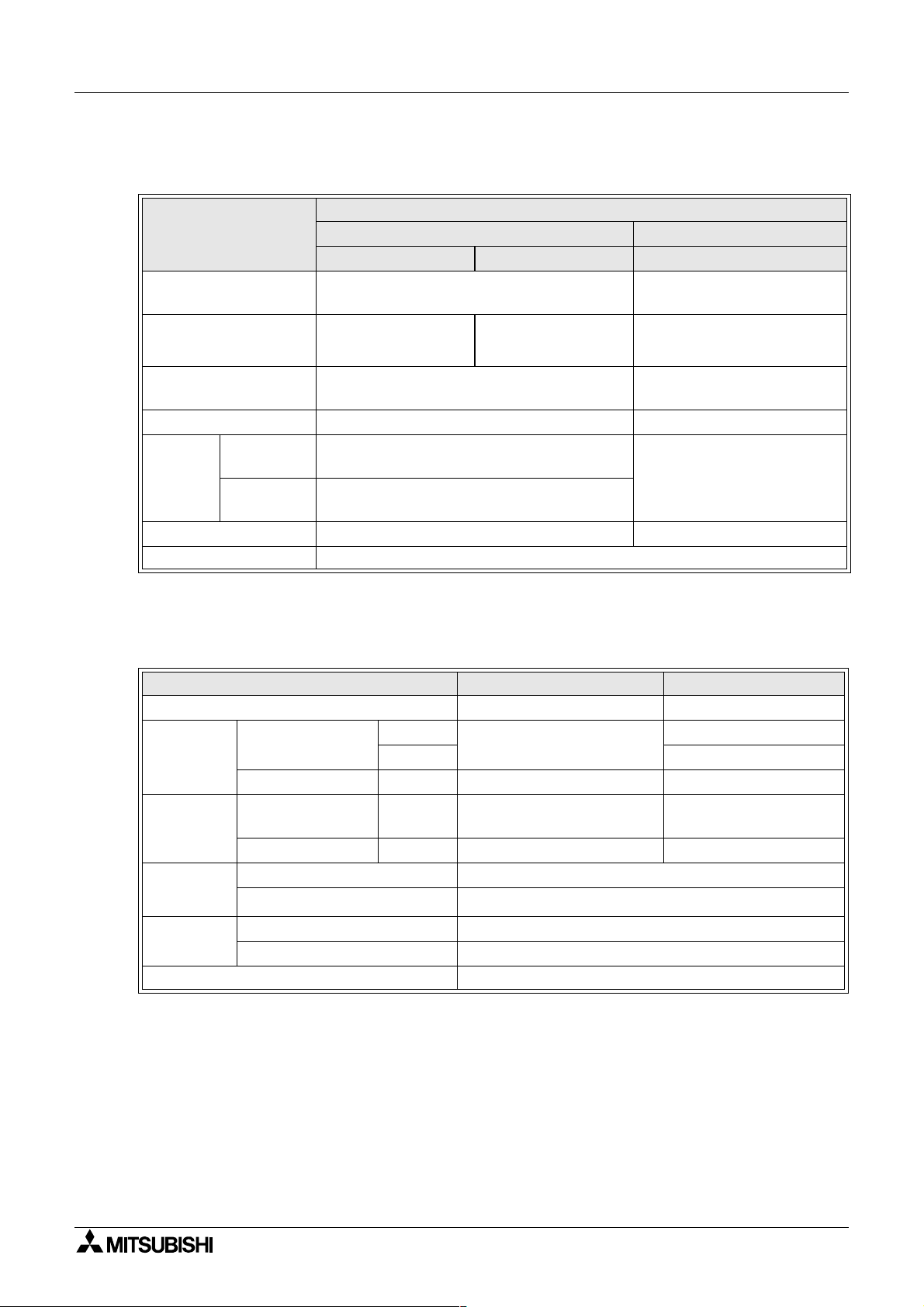
2.2 Input Specification
Table 2.2: AC Input Specifications
Description
Input Voltage 100 - 240V AC~, +10% -15%, 50/60 Hz
Input Current
Input Impedance ≥ 800 kΩ
OFF → ON/ ON → OFF ≥ 80V / ≤ 40V ≥ 160V / ≤ 40V
Response
Time
Isolation Circuit None Photocoupler
Operation Indication Liquid Crystal Display
OFF → ON
ON → OFF
main unit AL2-4EX-A2
I01 -I08 I09 -I15 EI1 -EI4
0.13mA / 120V AC~
0.25mA / 240V AC~
35-85ms, 120V AC~
25-55ms, 240V AC~
35-85ms, 120V AC~
50-130ms, 240V AC~
AC Input Specification
*1
0.15mA / 120V AC~
*1
0.29mA / 240V AC~
Specifications 2
220 - 240V AC~, +10% -15%,
50/60 Hz
*1
7.5mA / 240V AC~ 50Hz
*1
9.0mA / 240V AC~ 60Hz
32kΩ (50Hz)
27kΩ (60Hz)
15 - 40ms / 240V AC~
*1 Current leakage from the sensors connected to the inputs might provide enough current
to turn the controller On. Do not use two wire sensors
Table 2.3: DC Input Specifications
Description Sink(“-” Common) Source (“+”Common)
Input Voltage 24V DC +20% -15% 24V DC +20% -15%
Input
Current
main unit
I01 - I08
I09 - I15 5.5mA, 24V DC
5.5mA, 24V DC
6.0mA, 24V DC
AL2-4EX EI1 - EI4 5.4mA, 24V DC 5.4mA, 24V DC
OFF → ON/
ON → OFF
main unit I01 - I15
Current: ≥ 4.7mA / ≤ 1.1 mA
Voltage: ≤ 4V / ≥ 18V
Voltage: ≥ 18V / ≤ 4V
AL2-4EX EI1 - EI4 Voltage: ≥ 18V / ≤ 4VVoltage: ≥ 18V / ≤ 4V
Response
Time
Isolation
Circuit
main unit 10 - 20ms
AL2-4EX
*1
10 - 20ms
main unit None
AL2-4EX Photocoupler
Operation Indication Liquid Crystal Display
0
*1 EI1 and EI2 in AL2-4EX canbeusedasHighSpeedCounters.
When using the High Speed Counter function, the input response time is 0.5ms or less.
ENG-8
Page 19
α
2 Simple Application Controllers
Table 2.4: Analog Input Specifications (Only AL2-***-D Type Unit)
Description Analog Input Specification
Number of Input Points 8 (I01 - I08)
Analog Input Range 0 - 500
Resolution 9 bit, 20mV (10000/ 500mv)
Conversion Speed 8ms
Input Voltage 0 - 10V DC
Input Impedance 142kΩ ± 5%
Overall Accuracy ± 5% (0.5V DC)
Offset/Gain
Temperature Drift ± 3LSB
Specifications 2
ENG
Offset Value = 0at0V DC
Gain Value: 0 - 10V=0-500
These default values can be changed in the OffsetGain FB
ENG-9
Page 20
α
2 Simple Application Controllers
2.3 Output Specification
Table 2.5: Relay Output Specifications
Description Relay Specification
Switched Voltage 250V AC~ or less, 30V DC or less
AL2-14MR-* (O01 - O06)
Max. Resistive Load
Contact Life Cycle /
Resistance Load
Minimum Load 50mW (10mA at 5V DC)
Max. Inductive Load
Response Time ≤ 10 ms
Operation Indication Liquid Crystal Display
Isolation Circuit By Relay
AL2-24MR-* (O01 - O04)
AL2-24MR-* (O05 - O09) 2A/point (4A/COM)
AL2-4EYR (EO1-EO4) 2A/point
AL2-14MR-* (O01 - O06)
AL2-24MR-* (O01 - O04)
AL2-24MR-* (O05 - O09)
AL2-4EYR (EO1-EO4)
AL2-14MR-* (O01 - O06)
AL2-24MR-* (O01 - O04)
AL2-24MR-* (O05 - O09)
AL2-4EYR (EO1-EO4)
Specifications 2
8A/COM
100,000 Cycles at 8 Amps / 240V AC~ or 24V DC
100,000 Cycles at 2 Amps / 240V AC~ or 24V DC
249 VA (1/3 hp) / 125V AC~,
373 VA (1/2 hp) / 250V AC~
93 VA(1/8hp)/125V AC~,
93 VA(1/8hp)/250V AC~
Table 2.6: Transistor Output Specifications (Source Type only) of AL2-4EYT
Description Transistor Specification
Switched Voltage 5 - 24V DC (+20%,-5%)
Max. Resistive Load 1A / point (8 - 24V DC), 0.1A / point (5 - 8V DC)
Minimum Load 1.0mA
Max. Inductive Load 1A / 24V DC (24 W)
Response Time On/Off, Off/On (approx) ≤ 1ms
Open Circuit Current Leakage ≤ 0.1mA / 24V DC
Operation Indication Liquid Crystal Display
Isolation Circuit Photocoupler
ENG-10
Page 21
α
2 Simple Application Controllers
2.4 General Specification
Table 2.7: Environmental and Electrical Specifications
Description Specification
Programming Method Function Block
Program Capacity 200 Function Blocks or 5000 bytes
Program Storage
Device Backup 20 Days at 25°C / 77°F (by capacitor)
RTC Backup 20 Days at 25°C / 77°F (by capacitor)
RTC Accuracy 5 s / day (25°C / 77°F)
Operating Temperature
Storage Temperature (-30) - 70°C / (-22) - 158°F
Vibration Resistance
- Direct Mounting
Vibration Resistance
- DIN Rail mounting
Shock Resistance
Noise Immunity 1000Vpp, 1 µs, 30 - 100Hz, tested by noise simulator
Humidity 35 - 85% Relative Humidity, no condensation
Dielectric withstand
voltage
Insulation Resistance
Type of Action IEC 60730-1, Section 6.4.3 - Type 1C (Relay Output)
Type of Action IEC 60730-1, Section 6.4.3 - Type 1Y (Transistor Output)
Software Class IEC 60730-1, Section H6.18 - Class A
Purpose of Control IEC 60730-1, Section 2.2 - Electrical Control
Construction of Control IEC 60730-1, Section 6.15 - Incorporated Control
Whether the Control is
electric
Safety Class ΙΙ
Pollution Degree 2
Grounding None
Electrical Isolation Reinforced primary/secondary insulation
Operation Ambience To be free of corrosive gases. Dust should be minimal.
Protection IP 20
Specifications 2
Built in EEPROM (no battery backup required) or optional EEPROM
cassette (AL2-EEPROM-2)
Controller Hardware: (-25) - 55°C / (-13) - 101°F
Controller Display: (-10) - 55°C / 14 - 101°F
Conforms to IEC 68-2-6; 10-57Hz: 0.15mm Constant Amplitude
2
57-150Hz: 19.6m/s
Sweep Count for X,Y,Z: 10 times (80 minutes in each direction)
Conforms to IEC 68-2-6; 10-57Hz: 0.075mm Constant Amplitude
57-150Hz:9.8m/s
Sweep Count for X,Y,Z: 10 times (80 minutes in each direction)
2
Conforms to IEC 68-2-27: 147m/s
3 times in each direction X,Y, and Z
3750V AC~>1min per IEC 60730-1 between the following points:
Power/Input Terminals and Relay Output Terminals
Relay Output Terminal and Relay Output Terminal
All Terminals and the DIN 43880 Control box or equivalent
7MΩ at 500V DC per IEC60730-1 between the following points:
Power/Input Terminals and Relay Output Terminals
Relay Output Terminal and Relay Output Terminal
All Terminals and the DIN 43880 Control box or equivalent
IEC 60730-1, Section H2.5.7 - Electronic Control
Acceleration, Action Time: 11ms
Acceleration
2
Acceleration
ENG
ENG-11
Page 22

α
2 Simple Application Controllers
Table 2.7: Environmental and Electrical Specifications
Description Specification
Temperature for the Ball
Pressure Test
EC Directive EMC, LVD
Certifications UL/cUL
Attestation of Conformity TÜV PRODUCT SEVICE
Complies with
Liquid Crystal Display
*1 AL2-ASI-BD is not complied with these standards.
Specifications 2
75°C (167°F)
UL 508
IEC 60730-1
*1
*1
EN 61010-1
EN 50081-1
*1
EN 50082-1
EN 61000-6-2
Will display 4 lines of 12 characters per line, Program Run On/Off mode,
Password Protection, Image Table, and Function Blocks during
programming.
ENG-12
Page 23
α
2 Simple Application Controllers
3. Installation
3.1 Installation Mounting Notes
Theα2 Series’ safe design means the user can install it almost anywhere but please take
the following points into consideration.
Installation 3
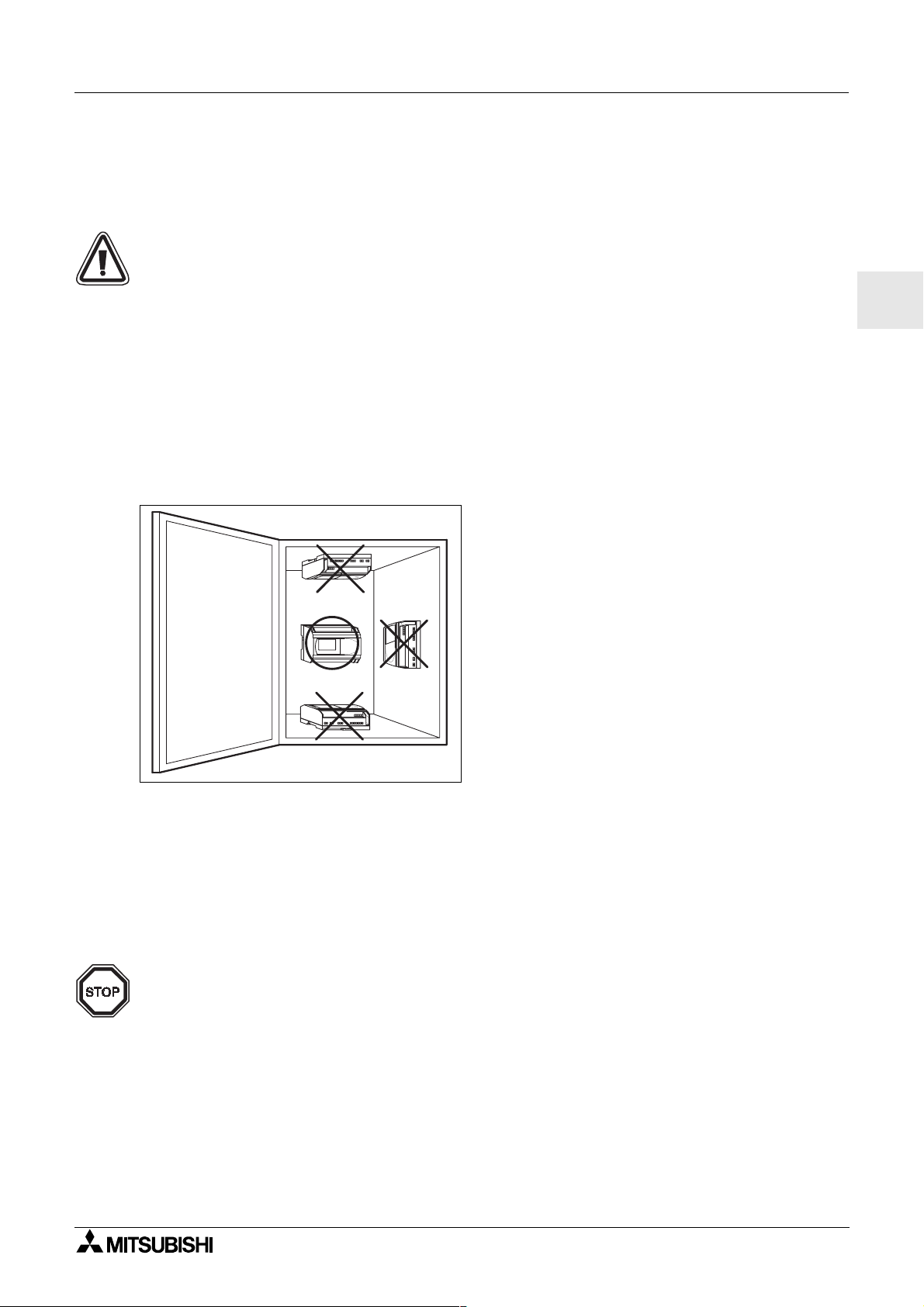
• Do not install in areas with excessive or conductive dust, corrosive or flammable gas,
moisture or rain, excessive heat, regular impact shocks or excessive vibration. Do not
place in water or let water leak onto the controller.
• Do not allow debris to fall inside the unit during installation.
• Keep as far as possible from high-voltage cables and power equipment.
•The
α
2 Series Controller must be installed in cabinets which are designed for the
assembly of devices complying to DIN 43880 or in a control box
Figure 3.1: Mounting Arrengement.
ENG
•Usesize M4 screws when mounting by screw holes.
• The connectors must be covered to prevent injury from contact with “live” wires.
• Leave a minimum of 10mm of space for ventilation between the top and bottom edges of
α
the
2 Series Controller and the enclosure walls.
• Do not disassemble the
α
2 Series controller.
Note;
• Refer to chapter 6 when installing or removing the AL2-EEPROM-2.
• Refer to chapter 7 when installing or removing the AL-232CAB.
• Refer to chapter 8 when installing or removing the AL2-GSM-CAB.
ENG-13
Page 24
α
2 Simple Application Controllers
3.2 DINRAILMountingofMainUnit
Units can be snap mounted to 35mm DIN rail (DIN EN 50022). To release pull the spring
loaded clips away from the rail and slide the unit off and up.
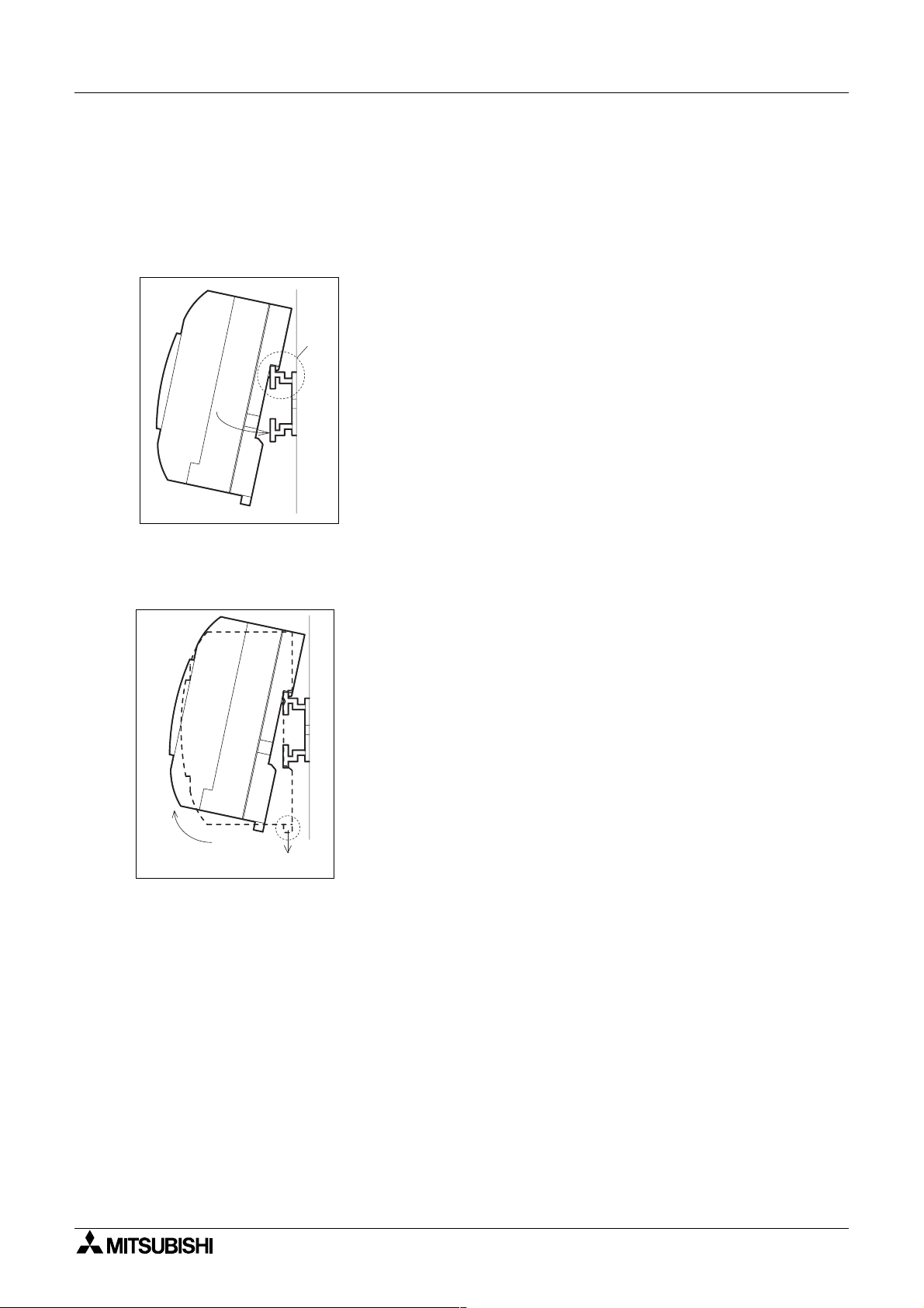
3.2.1 Installation
Figure 3.2: Installation
Align the upper side of theα2 DIN rail mounting groove with the
DIN rail () and push it onto the rail ().
Installation 3
3.2.2 Remove
Figure 3.3: Remove
Pull the DIN rail hook () and remove theα2 series main unit()
ENG-14
Page 25
α
2 Simple Application Controllers
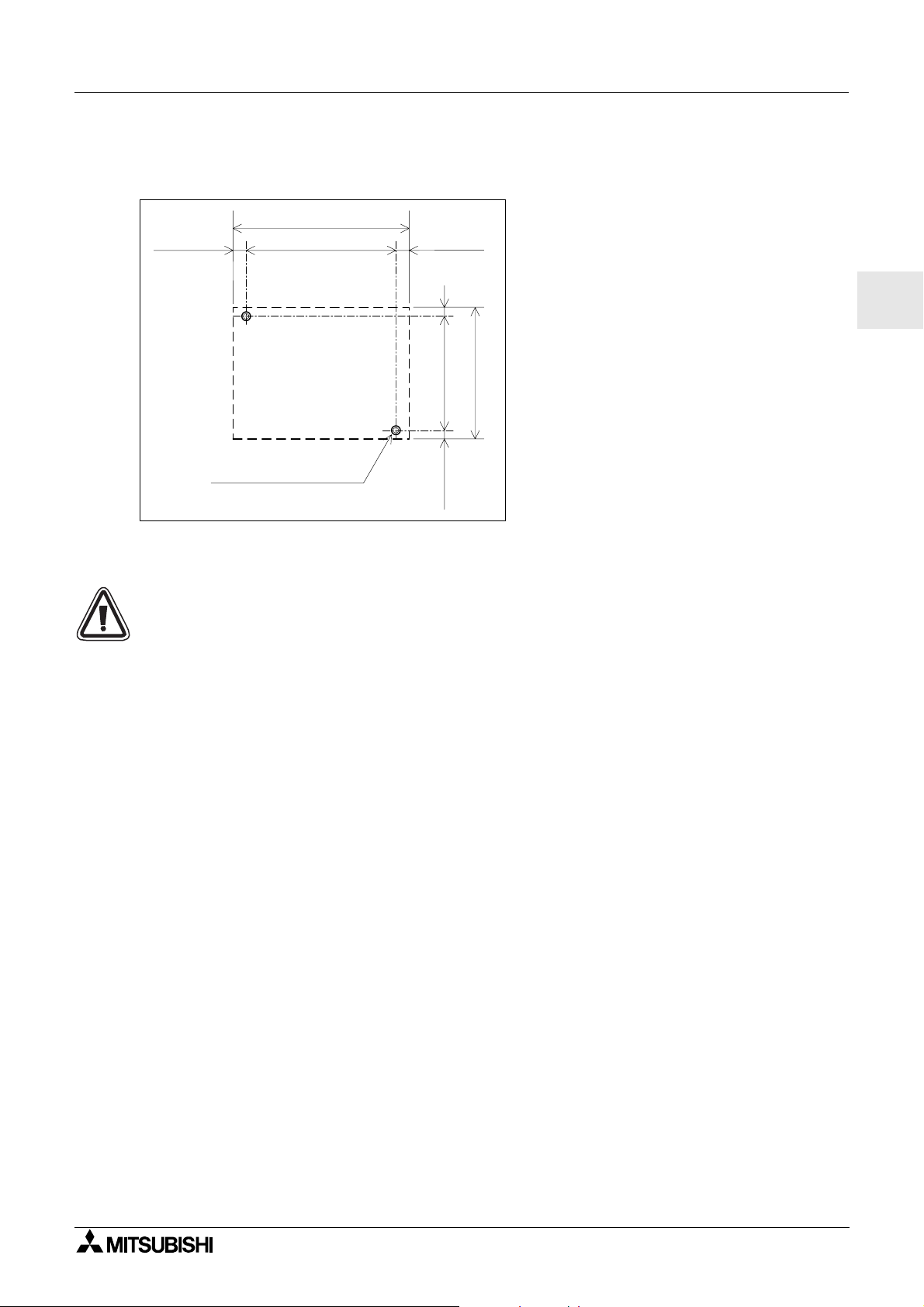
3.3 Direct Mounting of Main Unit
Figure 3.4: Direct Mounting
124.6 (4.91")
6(0.24")
M4 Mounting Screw
112.6 (4.43")6(0.24")
Main Unit
Installation 3
4
(0.16")
90 (3.54")
82 (3.23")
4 (0.16")
ENG
3.4 Install Extension Module
Caution:
Disconnect all terminals from the power supply before removing the cover.
ENG-15
Page 26
α
2 Simple Application Controllers
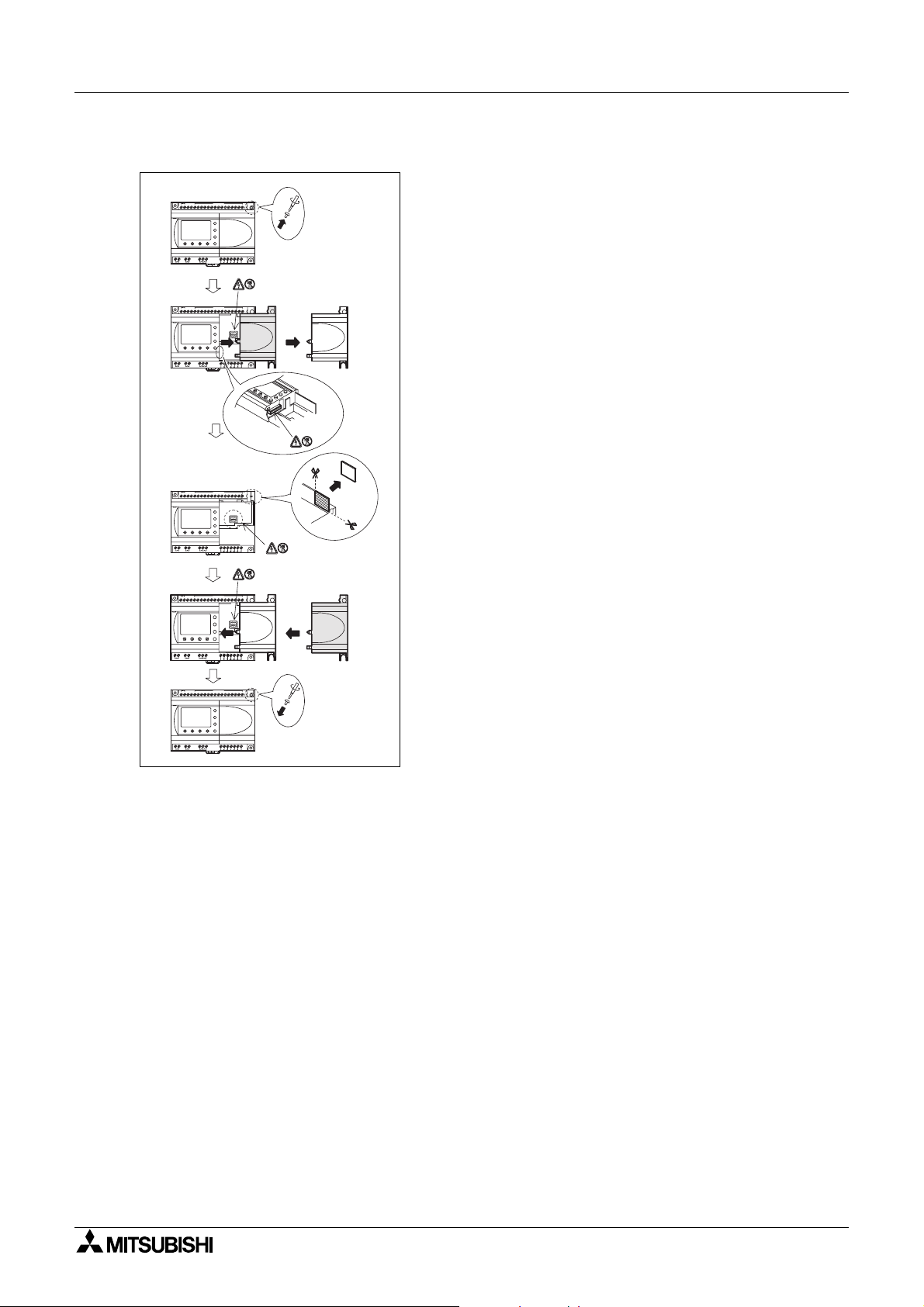
Figure 3.5: Installation
Installation 3
1)
2)
3)
4)
+-
POWER
24V DC
AL2-24MR-D
OUT1
OUT3
OUT2 OUT4
(A)(B)123456789101112131415
-+
POWER
24V DC
AL2-24MR-D
OUT4OUT28OUT
OUT3
OUT1
(A)(B)123456789101112131415
-+
POWER
24V DC
AL2-24MR-D
OUT4OUT28OUT
OUT3
OUT1
(A) (B) 1 2 3 4 5 6 7 8 9 10 11 12 13 14 15
-+
POWER
24V DC
AL2-24MR-D
OUT4OUT28OUT
OUT3
OUT1
DC INPUT
151413121110987654321(B )(A)
ESC
+
-
OK
RELAY
OUTPUT
9
65
8
7
OUT
DC INPUT
ESC
+
-
OK
RELAY
OUTPUT
7
5
9
DC INPUT
ESC
+
-
OK
RELAY
OUTPUT
7
56
9
DC IN P U T
ESC
+
-
OK
RELAY
OUTPUT
6
7
5
9
A
B
1) Release screw ‘A’ and keep.
2) Carefully remove the factory fitted expansion
port cover.
3) Cut away section ‘B’ from the
α
2series
controller main unit.
4) Attach the expansion module to the main unit.
5) Tighten screw ‘A’ to a torque of 0.4 N·m.
5)
AL2-24MR-D
OUT1
+-
POWER
24V DC
OUT2 OUT4
DC INPUT
151413121110987654321(B )(A)
ESC
+
-
OK
RELAY
OUTPUT
9
65
8
7
OUT3
OUT
A
ENG-16
Page 27
α
2 Simple Application Controllers
4. Wiring
4.1 Installation Wiring Notes
The wiring ofα2 Series has been designed to be safe and easy. A technician or engineer
trained in the local and national electrical standards should perform all tasks associated
with the electrical wiring of the
performing any wiring operations.
• Input and output cables should not be run through the same multicore cable or share the
same wire.
• Do not lay input/output cables near high voltage power cables.
• Input and output cable length must be than 30m (98' 5").
Allow for voltage drop and noise interference with input/output lines used over an extended
distance. Please use wire that is properly sized for the current load.
The terminal will accept a 3 mm flathead screwdriver.
α
2 Series controllers. Turn OFF the Power before
Wiring 4
ENG
ENG-17
Page 28
α
2 Simple Application Controllers
4.2 Wire Size
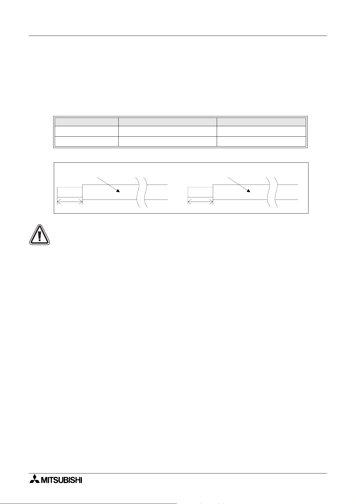
Wire of the Inputs and Outputs using the following wire. Strip the wire to the following length
(See Table 4.1 and Figure 4.1). Please unscrew the terminal to its widest position before
inserting a wire. Insert the wire completely into the terminal to ensure that a proper connection
canbemade.
The terminals will accept a 3mm flathead screwdriver.
Table 4.1: Wire Size
Main Unit
Extension Module
Figure 4.1: Wire Size
Main unit Extension module
Wire Size Strip Wire Length
26 - 12 AWG (0.13 - 3.31mm
24 - 14AWG (0.2 - 2.5mm
2
)
Wiring 4
2
)
7mm ± 0.5mm
6mm ± 0.5mm
26 -12 AWG
7mm(0.276") ± 0.5mm(0.02")
24 -14 AWG
6mm(0.236")
Note;
• To avoid damaging the wire, tighten to a torque of 0.5 - 0.6 N⋅m.
• Please do not use tin, solder, or any other substance on the stripped wire that might
causethewirestrandtobreak.
- Stranded cable:
Remove sheath, twist core wires, then connect cable (or use a crimp terminal).
- Single cable:
Remove sheath, then connect cable.
ENG-18
Page 29
α
2 Simple Application Controllers
4.3 Power Supply
• When wiring AC supplies the “Live” cable should be connected to the “L” terminal and
the “Neutral” cable should be connected to the “N” terminal. Do NOT connect the “Live”
wire to the “N” terminal, the user might receive a dangerous shock on powerup.
• When wiring DC supplies the “positive” cable should be connected to the “+” terminal
and the negative cable should be connected to the “-” terminal. On no account should
the power supply terminals be connected to any other terminal on the unit. DC Power
Supply units should be capable of providing 4 Amperes of current to the controller.
Figure 4.2: Recommended Power Input Wiring Diagram
L
+
N
Start
MC
MC
L
+ -
Wiring 4
ENG
N
"L" and "N" terminals are
not reversible.
Table 4.2: Recommended Power Wiring
Ref. Item Description
Power supply
1
AL2-***-A: 100-240V AC, 50/60Hz
AL2-***-D: 24V DC
2 Circuit isolation device
3 Power ON pilot indicator
4 Circuit protection device - Limit to 1.0A
5
α
2mainunit
6 Emergency stop
7 Magnetic switch contact
8 Power supply for loads
ENG-19
Page 30
α
2 Simple Application Controllers
4.4 AC Power Supply and Input Wiring
4.4.1 AC Power Supply and Input Wiring
Figure 4.3: AC Power Supply and Input Wiring Diagram
L
N
"L" and "N" terminals
are not reversible.
Wiring 4
LN 123456
Table 4.3: AC Power Supply and Input Wiring
Ref. Item Description
1 AC power supply, 100 - 240V AC~, 50/60Hz
2 Circuit isolation device
3 Circuit protection device - Limit to 1.0 Amp
4 AC power terminals
5 Unused terminals
6 Input terminals
7 Digital input switches
4.4.2 AL2-4EX-A2 Input Wiring
Figure 4.4: AL2-4EX-A2 Input Wiring Diagram
L
N
"L" and "N" terminals
are not reversible.
INPUTS
78
EI1 EI2
COM
(N)
EI3 EI4
Table 4.4: AC Power Supply and Input Wiring
Ref. Item Description
1 AC power supply, 220 - 240V AC~,50/60Hz
2 Circuit isolation device
3 Circuit protection device - Limit to 1.0 Amps
4COM (N) terminal
5 Input terminals
6 Digital input switches
ENG-20
Page 31

α
2 Simple Application Controllers
4.5 DC Power Supply and Input Wiring
4.5.1 DC Power Supply and Source (“+” Common) Input Wiring Diagram
Figure 4.5: DC Power Supply and Source (“+” Common) Input Wiring Diagram
Wiring 4
+ -
(A) (B)
2
1
456
3
INPUTS
78
Table 4.5: DC Power Supply and Source (“+” Common) Input Wiring
Ref. Item Description
DC power supply, 24V DC
1
2 Circuit isolation device
Circuit protection device - Limit to 1.0A
3
DC power terminals
4
Sink/Source input wiring terminals
5
Sensor input switches
6
Input terminals
7
Analog input
8
4.5.2 AL2-4EX Source (“+”Common) Input Wiring Diagram
Figure 4.6: AL2-4EX Source (“+” Common) Input Wiring Diagram
ENG
EI1
EI1
EI2
EI2
EI3
EI3
(+)
(-)
(+)
(-)
(+)
EI4
(-)
(+)
EI4
(-)
Table 4.6: DC Power Supply and Source (“+” Common) Input Wiring
Ref. Item Description
DC power supply, 24V DC
1
2 Circuit isolation device
Input terminals
3
Sensor input switches
4
Note:
Each input terminal (EI1 ~ EI4) can be used as either Source input or Sink input.
ENG-21
Page 32

α
2 Simple Application Controllers
4.5.3 DC Power Supply and Sink(“-” Common) Input Wiring Diagram
Figure 4.7: DC Power Supply and Sink (”-” Common) Input Wiring Diagram
Wiring 4
+ -
(A) (B)
2
1
456
3
INPUTS
78
Table 4.7: DC Power Supply and Sink (“-” Common) Input Wiring
Ref. Item Description
DC power supply, 24V DC
1
2 Circuit isolation device
Circuit protection device - Limit to 1.0 Amps
3
DC power terminals
4
Sink/Source input wiring terminals
5
Sensor input switches
6
Input terminals
7
4.5.4 AL2-4EX Sink(“-” Common) Input Wiring Diagram
Figure 4.8: AL2-4EX Sink (”-” Common) Input Wiring Diagram
EI1
(+)
EI1
EI2
EI2
(-)
(+)
EI3
(-)
(+)
EI3
(-)
EI4
(+)
EI4
(-)
Table 4.8: DC Power Supply and Sink (“-” Common) Input Wiring
Ref. Item Description
DC power supply, 24V DC
1
2 Circuit isolation device
Input terminals
3
Sensor input switches
4
Note:
Each input terminal (EI1 ~ EI4) can be used as either Source input or Sink input.
ENG-22
Page 33

α
2 Simple Application Controllers
4.6 Output Relay and Transistor Wiring
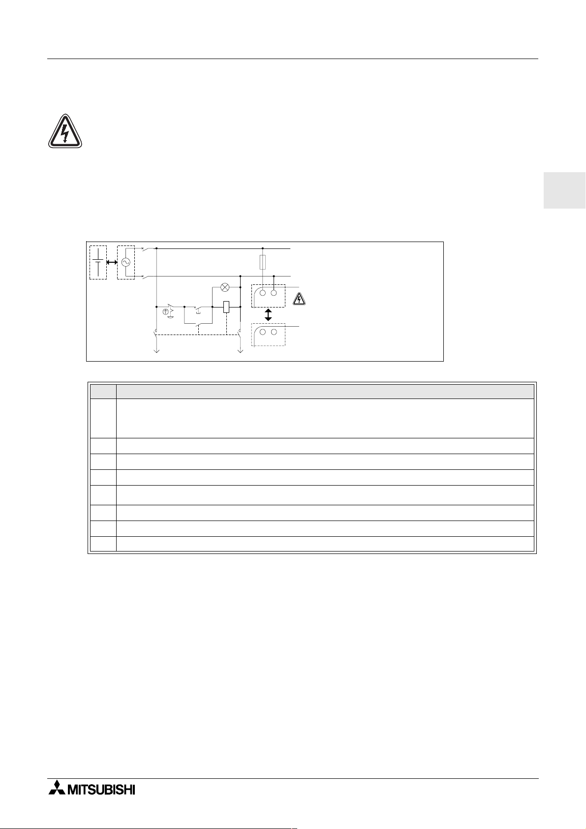
4.6.1 Relay Output Wiring Diagram main unit (AC and/or DC)
Figure 4.9: Relay Output Wiring Diagram main unit (AC and/or DC)
OUT1
Table 4.9: Relay Output Wiring main unit (AC and/or DC)
Ref. Item Description
1
2mainunit
α
2 Mutually exclusive outputs
3 Output devices
4 Circuit protection device (SeeTable 4.10)
5 Emergency stop
6 DC power supply
7 AC power supply
OUT2 OUT3 OUT4
OUT5 OUT6
Wiring 4
ENG
Table 4.10: Relay Output Circuit Protection Table
Model
AL2-14MR-*O01~O06
AL2-24MR-*
Number of
Output
O01~O04 ≤ 10A / Circuit
O05~O09 2A/point (4A/common) ≤ 3A / Circuit
Max. ResistiveLoad
8A/common
Circuit Protection
(Fuse)
≤ 10A / Circuit
ENG-23
Page 34

α
2 Simple Application Controllers
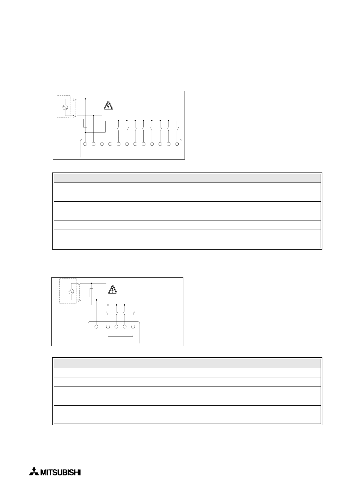
4.6.2 Relay Output Wiring Diagram AL2-4EYR (AC and/or DC)
Figure 4.10: Relay Output Wiring Diagram AL2-4EYR (AC and/or DC)
EO1 EO2 EO3 EO4
Table 4.11: Relay Output Wiring AL2-4EYR (AC and/or DC)
Ref. Item Description
1 DC power supply
2 Emergency stop
3 Circuit protection device (Fuse: ≤ 3A)
4 Mutually exclusive outputs
5 Output devices
6 AC power supply
Wiring 4
Table 4.12: Relay Output Circuit Protection Table
Model
AL2-4EYR EO1~EO4 2A/common ≤ 3A / Circuit
Number of
Output
Max. ResistiveLoad
Circuit Protection
(Fuse)
ENG-24
Page 35

α
2 Simple Application Controllers
4.6.3 Transistor Output (Source or “+” Common Only) Wiring Diagram AL2-4EYT
Figure 4.11: Transistor Output (Source/ “+” Common Only) Wiring Diagram AL2-4EYT
Wiring 4
EO1 EO2 EO3 EO4
-
+
-+
Table 4.13: Transistor Output Wiring
Ref. Item Description
1 DC Power Supply: 24V DC
2 Emergency Stop
3 Circuit Protection Device - See Table 4.14 for Specifications
4 Power Supply Terminal
5 Output Devices
6 DC Power Supply: 12V DC
Table 4.14: Transistor Output Circuit Protection Table
Circuit
Volt age
5V DC <
12V DC <
24V DC < 2.0A/Circuit
Circuit Protection (Fuse)
0.3A/Circuit
2.0A/Circuit
*1
*1
ENG
*1 Power Source capacity≥Fuse size×2
Figure 4.12: Example Fuse Size Calculation
12V,8A
(8A
≥1A×2×
4)
Fuse
1A
O01
Fuse1AFuse1AFuse
1A
O02 O03 O04
Note;
Table 4.15: Output Terminal Notes
Volt Output Terminal Notes
5 Each circuit can contain from one output terminal up to every output terminal.
12-24 Each circuit can contain from one output terminal up to every output terminal.
5,12,24
Using any combination of 5 Volt, 12 Volt, and 24 Volt outputs can be accomplished on the
2 Series Controller if separate circuits are used for each voltage level.
α
same
ENG-25
Page 36

α
2 Simple Application Controllers
Wiring 4
MEMO
ENG-26
Page 37

α
2 Simple Application Controllers
5. Terminal Layout
Figure 5.1: AL2-14MR-A, AC Input, Relay Output
LN
1
IN
34567
2
Terminal Layout 5
8
AL2-14MR-A
OUT1
OUT2
OUT3
OUT4 OUT6
OUT5
Figure 5.2: AL2-14MR-D, DC Input, Relay Output
IN
+ -
AL2-14MR-D
OUT1
(A)
(B)
OUT2
1
34567
2
OUT3
8
OUT4 OUT6
OUT5
Figure 5.3: AL2-24MR-A, AC Input, Relay Output
IN
LN
1
34567
2
8
9
10 11
12
13 14
ENG
15
AL2-24MR-A
OUT1
OUT2
OUT3
OUT4
OUT
Figure 5.4: AL2-24MR-D, DC Input, Relay Output
IN
+ -
AL2-24MR-D
OUT1
(A)
(B)
OUT2
1
34567
2
OUT3
OUT4
8
OUT
9
5
10 11
5
67
12
67
8
13 14
8
9
15
9
ENG-27
Page 38

α
2 Simple Application Controllers
Figure 5.5: AL2-4EX-A2, 220 - 240V AC Input
IN
EI1
COM(N)
AL2-4EX-A2
EI2 EI3
Figure 5.6: AL2-4EX, DC Input
Terminal Layout 5
EI4
+
+
EI2
-
-
EI1
-
+
AL2-4EX
+
-
EI3 EI4
Figure 5.7: AL2-4EYR, Relay Output
EO1
AL2-4EYR
EO3EO4
EO2
Figure 5.8: AL2-4EYT, Transistor Output
-
+
AL2-4EYT
+
EO1
EO2
-
EO3
EO4
ENG-28
Page 39

α
2 Simple Application Controllers
6. AL2-EEPROM-2
The AL2-EEPROM-2 memory cassette is for use only with theα2 series controller
(Model: AL2-**M*-*).
Caution
AL2-EEPROM-2 6
• Persons trained in the local and national electrical standards must replace the memory
cassette.
• Turn off the power supply when installing or removing the memory cassette.
• Replace the cover after removing the memory cassette.
α
• When installing the connector cover or the memory cassette of
to pinch your finger.
•DO NOT touch the following part when removing the cover or memory cassette.
2series,becarefulnot
ENG
ENG-29
Page 40

α
2 Simple Application Controllers
6.1 Installation
1) Remove the cover or the memory cassette
2) Install on the cover or the memory cassette
AL2-EEPROM-2 6
ENG-30
Page 41

α
2 Simple Application Controllers
7.AL-232CAB
7.1 Introduction
The AL-232CAB is an RS-232C cable used to connect anαseries controller (α,α2) and a
personal computer that is running the programming software (AL-PCS/WIN-E).
AL-232CAB 7
Note:
• AL-232CAB cable cannot be used for any other applications.
• AL-232CAB cable rises about 40mm (1.57") above the top panel when connecting to an
α
2 series controller.
7.1.1 External Dimensions
α
2seriesside
30.8(1.21")
47.8(1.88")
46(1.81")
11.5(0.45")
2500(8'2")
RXD(RD)
TXD (SD)
D T R (E R )
GND(SG)
Dimensions: mm (inches)
0
Personal computer side
(9-pin D-Sub female)
*1 Set this signal to
*1
high-level.
ENG
ENG-31
Page 42

α
2 Simple Application Controllers
7.2 Connected to AL-232CAB cable
Removecover and memory cassette
• Be careful of personal safety when removing theα2cover.
Caution
• Turn off the power supply when you install or detach the AL-232CAB cable.
• Install the cover or the memory cassette after removing the AL-232CAB cable.
• When installing the connector cover or the memory cassette of
to pinch your finger.
• Please hold the protective case when detaching the cable. DO NOT pull on the cord.
•DO NOT touch the following part when removing the cover, memory cassette or this
cable.
AL-232CAB 7
α
2series,becarefulnot
1) Removing the cover or the memory cassette
ENG-32
Page 43

α
2 Simple Application Controllers
2) Connecting the AL-232CAB cable
3) Removing the AL-232CAB cable
AL-232CAB 7
ENG
ENG-33
Page 44

α
2 Simple Application Controllers
4) Installing on the cover or the memory cassette
AL-232CAB 7
ENG-34
Page 45

α
2 Simple Application Controllers
AL-232CAB 7
MEMO
ENG
ENG-35
Page 46

α
2 Simple Application Controllers
8. AL2-GSM-CAB
8.1 Introduction
The AL2-GSM-CAB can be used to connectα2 Series Controllers to a normal or GSM
modem. The AL2-GSM-CAB can transfer Short Message Service (SMS) data to a GSM
modem for transmission to mobile phones and mail addresses or can facilitate remote
monitoring functions and program transfers via normal modems. RS-232C communication to a
personal computer can also be accomplished if an adaptor or cable is used.
Further information can be found in the
Note:
• This cable cannot be used for any other applications.
AL2-GSM-CAB 8
α
2 Programming Manual andαSoftware Manual.
• This cable does not attach to the
• Simultaneous communication through both ports of theα2 Series Controllers may result
in a damaged program or a malfunction in the controller.
8.1.1 External Dimensions
Figure 8.1: External Dimensions Dimensions: mm (inches)
α
2seriesside
34.2
(1.35")
(1.82")
46.3
α
Series Controller (Model: AL-**M*-*).
1500(4'11")
10.2(0.4")
modem side
(9-pin D-Sub male)
ENG-36
Page 47

α
2 Simple Application Controllers
8.1.2 System Configuration with using AL2-GSM-CAB
Figure 8.2: System Configuration with AL2-GSM-CAB
UsingDedicatedProtocol
α
2
Series
AL2-GSM-CAB 8
Remote Maintenance (Via Telephone Line)
Normal Modem Normal Modem
Remote Maintenance, E-Mail (Via GSM)
Normal Modem
GSM
Modem
Sending SMS Message
Table 8.1: System Configuration with AL2-GSM-CAB
Item Using Cable
1AL2-GSM-CAB
2 RS-232C cross cable (See Figure 8.3)
3 RS-232C straight cable for the modem (See Figure 8.5)
4 RS-232C straight cable for the modem (specified by modem manufacturer)
Personal computer
- Programming Software
(AL-PCS/WIN-E)
Cellular Phone
(Supporting SMS message)
- Dedicated protocol
- E-Mail application
ENG
Figure 8.3: RS-232C Cross Cable Reference
(9-pin D-Sub female) (9-pin D-Sub female)
2
3
4
5
6
7
8
3
2
6
5
4
8
7
Note:
The 4 and 7 signals must be set to high-level on the personal computer side.
If these signals are not set, it will not communicate to
α
2series.
ENG-37
Page 48

α
2 Simple Application Controllers
8.2 Installation
When installing AL2-GSM-CAB refer to Figure 8.4.
Caution
• Persons trained in the local and national electrical standards must install or remove the
AL2-GSM-CAB.
• Turn off the power supply when installing or removing the AL2-GSM-CAB.
• Put the cover back on after either installing or removing the AL2-GSM-CAB.
• Under no circumstances will Mitsubishi Electric be liable or responsible for any
consequential damage that may arise as a result of the installation or use of this
equipment.
• Do not pull on the cord, otherwise the cable may be damaged.
AL2-GSM-CAB 8
• When communicating to
must be turned ON at the same time. If they are not started up at same time, the
series will not communicate via GSM modem.
• Disconnect all terminals from the power supply before removing the cover.
α
2 series via GSM modem, the power supply for both units
α
2
ENG-38
Page 49

α
2 Simple Application Controllers
Figure 8.4: Installation
AL2-GSM-CAB 8
1)
2)
3)
4)
+-
POWER
24V DC
AL2-24MR-D
OUT1
OUT3
OUT2 OUT4
(A)(B)1 23 45 678 9101112131415
-+
POWER
24V DC
AL2-24MR-D
OUT4OUT28OUT
OUT3
OUT1
(A)(B)1 23 45 6 78 9101112131415
-+
POWER
24V DC
AL2-24MR-D
OUT4OUT28OUT
OUT3
OUT1
(A)(B)123456789101112131415
-+
POWER
24V DC
AL2-24MR-D
RELAY
OUTPUT
OUT4OUT28OUT
OUT3
OUT1
DC INPUT
151413121110987654321(B )(A)
ESC
+
-
OK
RELAY
OUTPUT
9
65
8
7
OUT
DC INPUT
ESC
+
-
OK
RELAY
OUTPUT
7
5
9
A
1) Release screw ‘A’ and keep.
2) Carefully remove the factory fitted
α
2 expansion
port cover or special module cover.
3) Install the AL2-GSM-CAB
into the cavity,
carefully placing the cable in the channel located
on the input terminal side.
α
4) Attach the
2 cover or expansion module taking
ENG
care that there is no interference with the AL2GSM-CAB.
5) Tighten screw ‘A’ to a torque of 0.4 Nm.
In s ta ll
DC INPUT
ESC
+
-
OK
RELAY
OUTPUT
7
56
9
DC INPUT
ESC
+
-
OK
6
7
5
9
Remove
5)
AL2-24MR-D
OUT1
+-
POWER
24V DC
OUT2 OUT4
DC INPUT
151413121110987654321(B )(A)
ESC
+
-
OK
RELAY
OUTPUT
9
65
8
7
OUT3
OUT
A
ENG-39
Page 50

α
2 Simple Application Controllers
8.3 Remote Maintenace with a Modem
Further information of the modem setup procedures can be found in theα2 Programming
Manual. The programming software (AL-PCS/WIN-E) provides the easiest method to setup
the modem.
8.3.1 Recommended Modems
Thefollowingmodemshavebeensuccessfullytested.
Table 8.2: Tested Modems
Maker name Model name Modem command (AT c ommand )
3com SP560V-P ATE0Q1&B1&D0H0&I0&R1&S0S0=2S15=8&W
OMRONME3314ATE0S0=2Q1&D0S15=8&R1&H0&W
AIWA PV-AF3360 ATE0S0=2Q1&D0&M5\Q0\J0&W
Siemens M20T ATE0S0=2&S0;+IFC=0,0;+CMEE=1;+IPR=9600&W
8.3.2 RS-232C Straight Cable Between Modem and AL2-GSM-CAB
Figure 8.5: RS-232C Straight Cable Reference Between a Modem and AL2-GSM-CAB
AL2-GSM-CAB 8
AL2-GSM-CAB Side
(9-pin D-Sub female)
1
2
3
4 20
5
6
7
8
9
Modem Side
(25-pin D-Sub male)
1
8
3
2
7
6
4
5
22
ENG-40
Page 51

α
2 Simple Application Controllers
8.3.3 Modem Setting
1) Setting of personal computer side
Install the file for the setting of the attachment in the modem.
AL2-GSM-CAB 8
2) Setting of
The modem on the
α
2seriesside
α
2 series side is set by the ModemInit command of the main unit.
a) About the modem command (AT command)
Use the AT command to initialize the modem. Confirm details of the AT command in the
manual of the modem to be used. AT commands have been prepared for select modems
in the table 8.4 (normal modem) and 8.5 (GSM modem) below.
Table 8.3: Tested Modems
Maker name Model name Modem command (AT command)
3com SP560V-P ATE0Q1&B1&D0H0&I0&R1&S0S0=2S15=8&W
OMRON ME3314 ATE0S0=2Q1&D0S15=8&R1&H0&W
AIWA PV-AF3360 ATE0S0=2Q1&D0&M5\Q0\J0&W
Siemens M20T ATE0S0=2&S0;+IFC=0,0;+CMEE=1;+IPR=9600&W
Further information on the method to initialize a modem can be found in the
Programming Manual.
When modems not listed in the table above are used, set the AT command to meet the
following requirements.
Table 8.4: AT Command for Modem (Normal Modem)
Setting Item Set content
Setting of command echo None E0 E0 E0
Call frequency of auto-answering Twice S0=2S0=2S0=2
Displayed result code None Q1 Q1 Q1
DTR control Always on &D0 &D0 &D0
DSR control Always on &S0
Communicate mode V.42bis mode S15=8S15=8 &M5
Speed of terminal fixed dimension Fixed &B1 \J0
Terminal flow control scheme None -&R1 \Q0
Flow control of transmission data None &H0 &H0 Flow control of received data
(software)
Flow control of received data
(RTS control)
Writing in nonvolatile memory
None &I0
None &R1
Writeinthe
nonvolatile
memory.
SP560V-P ME3314 PV-AF3360
&W &W &W
Example Setting
α
ENG
2
ENG-41
Page 52

α
2 Simple Application Controllers
Table 8.5: AT Command for GSM Modem
Setting Item Set content
Enable command echo Echo mode OFF E0
Set number of ring before
automatically answering the call
Set circuit data set ready (DSR)
function mode
Set TE-TA local data flow control
Report mobile equipment error Enable result code and use numeric value +CMEE=1
Set fixed local rate Baud Rate: 9600 bps +IPR=9600
Set circuit data carrier detect
(DCD) function mode
Select bearer service type
Store current parameter to use
defined profile
AL2-GSM-CAB 8
Example Setting
M20T
Enable automatic answering on the ring
twice
DSR always ON &S0
• Specifies the method which will be used
by TE when data is received fromTA:
None
• Specifies the method which will be used
by TA when data is received from TE:
None
*1
*1
DCD line is ON only in the presence of
Data Carrier
9600 bps (V.32), asynchronous modem,
non-transparent
The user profile is stored in non-volatile
memory
S0=2
+IFC=0,0
&C1
+CBST=7,0,1
&W
*1 In Siemens M20T case, these settings are not necessary because they are default
settings. If using other GSM Modem, maybe these settings are necessary.
b) Timing to initialize the modem during system startup
α
In the
2 series, there is a function to delay the transmission of the modem command
(AT command) to initialize the modem from the main unit at start up. The delay can
range from 0 - 10 seconds. This command can be useful to ensure the AT command is
correctly transmitted when the
Further information for the modem operation can be found in the
Manual and the
α
Software Manual.
α
2 series start up is faster than the modem start up.
α
2 Programming
ENG-42
Page 53

α
2 Simple Application Controllers
AL2-GSM-CAB 8
MEMO
ENG
ENG-43
Page 54

α
2 Simple Application Controllers
9. AL2-ASI-BD
The AL2-ASI-BD Actuator Sensor Interface board module is used in conjunction withα2
series controller for data communication over an Actuator Sensor Interface (AS-interface)
network.
Further information can be found in the
Caution
• Persons trained in the local and national electrical standards must replace the
AL2-ASI-BD.
• Turn off the power supply when you install or remove the AL2-ASI-BD.
• Replace the cover after removing the AL2-ASI-BD.
• Under no circumstances will Mitsubishi Electric be liable or responsible for any
consequential damage that may arise as a result of the installation or use of this
equipment.
9.1 Introduction
α
2 Series Programming Manuals.
AL2-ASI-BD 9
The AL2-ASI-BD connects onto the main unit of theα2 series controller, forming a slave
station for an AS-interface network (Input 4 points, Output 4 points). A maximum of 31 slaves
can be connected to form an AS-interface network. Power for the communication is supplied
over the AS-interface bus by the AS-interface power supply. The communication signal is
superimposed over the power supply on the AS-interface bus.
9.1.1 External Dimensions
Figure 9.1:
External
Dimensions Unit: mm (inches)
ASI+
ASI+
ASI-
ASI-
90(3.54")
24.5(0.96")
5 3 .1 (2 .0 9 ")
ENG-44
Page 55

α
2 Simple Application Controllers
9.1.2 System Configuration
Figure 9.2: System Configuration
AL2-ASI-BD 9
AS-interface Master
Module
AS-interface
Power Supply
9.2 Specifications
For general specifications please refer to the Chapter 2.
Table 9.1: Hardware Communication Specifications
Number of I/O 4 Input (E01-E04) 4 Output (A01-A04)
I/O Refresh Time Max. 5ms
Network Distance Max. 100m
External Power Voltage Typ. 30.5V DC (AS-interface Power supply)
External Power Current Consumption 40 mA or less
EC Directive EMC
Complies with AS-interface Certification
AS-interface Slave
(Sensor / Actuator)
AS-interface Slave
(Sensor / Actuator)
Item Content
AS-interface Slave
α
2Series
(
+ AL2-ASI-BD)
AS-interface Slave
(Sensor / Actuator)
ENG
Table 9.2: Software Communication Specifications
Item Content
Station Number Set by Master Station (Factory default 0)
IO Code 7
ID Code F
Data Bit D0 - D3 Input/Output 01 - 04 (E01 - E04, A01 - A04)
Parameter Bit
System Bit
Control Bit N1
P0
P1,P2,P3 Unused
M6 “ON” when communication Error of AS-interface occurs
M7 “ON” when communication Error by AS-interface power fail occurs
Communication monitor (set by default).
ON: Connect to AS-interface network
OFF: Unconnected to AS-interface network
*1
*1 Function to reset input signal (E01 - E04) when AS-interface communication is cut for 70
ms or more.
ENG-45
Page 56

α
2 Simple Application Controllers
9.3 Wiring & Installation
9.3.1 Installation
Caution
Disconnect all terminals from the power supply before removing the cover.
Figure 9.3: Installation
AL2-ASI-BD 9
1)
2)
3)
4)
+-
POWER
24V DC
AL2-24MR-D
OUT1
OUT3
OUT2 OUT4
(A)(B)123456789101112131415
-+
POWER
24V DC
AL2-24MR-D
OUT4OUT28OUT
OUT3
OUT1
(A)(B)1 23 45 678 9101112131415
-+
POWER
24V DC
AL2-24MR-D
OUT4OUT28OUT
OUT3
OUT1
(A)(B)123456789101112131415
-+
POWER
24V DC
AL2-24MR-D
RELAY
OUTPUT
OUT4OUT28OUT
OUT3
OUT1
DC IN P U T
151413121110987654321(B )(A)
ESC
+
-
OK
RELAY
OUTPUT
9
65
8
7
OUT
DC INPUT
ESC
+
-
OK
RELAY
OUTPUT
7
5
9
DC IN P U T
ESC
+
-
OK
RELAY
OUTPUT
7
56
9
DC INPUT
ESC
+
-
OK
6
7
5
9
A
B
1) Release screw ‘A’ and keep.
2) Carefully remove the factory fitted expansion
port cover.
3) Cut away section ‘B’ from the
α
2series
controller main unit.
4) Attach the expansion module to the main unit.
5) Tighten screw ‘A’ to a torque of 0.4 Nm.
5)
AL2-24MR-D
OUT1
+-
POWER
24V DC
OUT2 OUT4
DC IN P U T
151413121110987654321(B )(A)
ESC
+
-
OK
RELAY
OUTPUT
9
65
8
7
OUT3
OUT
A
ENG-46
Page 57

α
2 Simple Application Controllers
9.3.2 Wiring
Use the AS-interface flat cable (yellow) for connecting the AL2-ASI-BD to the network.
When connecting AS-interface cable to the module, tighten communication connector pin
Figure 9.4: Wiring
AL2-ASI-BD 9
AS-interface Flat cable (Yellow)
ASI+ ASI-
AS-interface Master
Module
ASI+ ASI- ASI+ ASI-
AL2-ASI-BD
9.4 Slave Address Setting & Diagnostics
9.4.1 Setting SlaveAddress
The address of AL2-ASI-BD must be set from the AS-interface master module. The setting
range of the slave address is 1 to 31. New modules are preset to 0 before shipping, if a module
has been previously assigned an address other than 0, it must be reset to 0 before it need to
add into new AS-interface network.
Refer to the AS-interface master module's manual for details of how to set station address
from the AS-interface master.
Many modules can be added to a network at one time, all but one of them should be set in their
passive state (set N1=1). Once the network has been powered up the modules can be
individually activated (set N1=0), where the Master station will assign a slave address.
ENG
ASI+ ASI-
AS-interface Power
Supply
9.4.2 Applicable Error checks
1) If a Communication error (M6) occurs;
- Check connections to the AS-interface master, and that the slave station number is
correct.
2) If a Communications power supply error (M7) occurs;
- Check the connection of the AS-interface Bus cable at each affected unit, also the ASinterface power supply and its operation.
ENG-47
Page 58

α
2 Simple Application Controllers
Key, System Bit and Function Block Lists 10
10.Key, System Bit and Function Block Lists
10.1 Key Lists
The following table is the keys to use operation in the Menu and user program. Further
information can be found in
Table 10.1: Operation Key Lists
Key Name Key Number Description
OK K01 Acceptance of data entry, menu options, program choices
ESC K02 Cancel current operation, move to higher screen or menu
+ K03
-K04
K05
K06 Scroll to lower numbered items (keys, FB, Inputs, Outputs, etc.)
K07 Move to the right on the LCD display, FB program or Jump command
K08 Move to the left on the LCD display, FB program or Jump command
α
2 Programming Manual.
Connect function blocks, move to higher numbered blocks, increment
values
Disconnect function blocks, move to lower numbered blocks,
decrement values
Scroll to higher number numbered items (keys, FB, Inputs, Outputs,
etc.)
ENG-48
Page 59

α
2 Simple Application Controllers
10.2 System Bit Lists
There is the system bit controlled by system and the control bit to control from user program.
10.2.1 System Bit Lists
Table 10.2: System Bit Lists
System Bit Description
M01 Always “ON”
M02 Always “OFF”
M03 Alternate - 0.5 seconds “ON”, 0.5 seconds “OFF”
M04 “ON” when Real Time Clock data error occurs
M05 “ON” when Summer time schedule is activated
M06 “ON” when communication Error of AS-interface occurs
M07 “ON” when communication Error by AS-interface power failure occurs
Key, System Bit and Function Block Lists 10
ENG
M08
M09
M10 Reserved
M11 Reserved
M12 “ON” when CD (DCD) signal is turned ON (receiving CD signal from modem)
M13 “ON” when it is possible to access the GSM network.
M14
ONwhenturnStopmodeturnstoRunmodeinthe
pulse output and then turns OFF .
OFF when turn Stop mode turns to Run mode in the
as a pulse output and then turns ON.
“ON” when the
10.2.2 Control Bit Lists
Table 10.3: Control Bits
Control Bit Description
N01
*1
N02
*1
N03
N04
2 Series. The ON signal acts as a
α
2 Series. The OFF signal acts
α
2seriesisaccessedviaGSM.
α
ON: Disconnected to AS-interface network
OFF: Connect to AS-interface network
ON: The back light is “OFF”inLCD.
OFF: The back light is controlled by the “Light Time” setting in Menu.
ON: The back light is “ON” in LCD.
OFF: The back light is controlled by the “Light Time” setting in Menu.
ON: The user screen is controlled by the setting of “Display Manager” with AL-
PCS/WIN-E.
OFF: The user screen is controlled by user program.
*1 When both N02 and N03 are ON and hence the back light is “ON” because N03 is given
the priority.
ENG-49
Page 60

α
2 Simple Application Controllers
10.3 Function Block Lists
Further information for function blocks can be found in theα2 Series Programming Manual.
Table 10.4: Function Block Lists
Function Block Memory
Name Symbol
AND AND 19
OR OR19
NOTNOT10
XOR XOR13
NAND NAND 19
NORNOR19
Boolean BL *1 Logic equation using AND, OR, XOR, NOT
Set/Reset SR 14
Pulse PL 10 Send a Pulse on the Rising, Falling, or both Edges
Alternate AL 13
Delay DL 19 Delay a signal on the Rising, Falling, or both Edges
One Shot OS17
Flicker FL 19
Time Switch TS *2
Time Switch
Maintenance
Counter CN 16 Count upwards on pulses, can reset at a signal
Up/Down
Counter
Compare CP 17
Offset Gain OG22
Display DP *3
Zone
Compare
Schmitt trigger ST 19
Hour Meter HM 19 Records the accumulated time a signal has been ON
TSm *2
UD 22
ZC20
Consumption
(Byte)
Key, System Bit and Function Block Lists 10
Description
Output ON when all Inputs are ON, Unused inputs
considered ON
Output ON when at least one input ON, Unused inputs
considered OFF
Inverts a signal; changes an OFF to an ON and vice
versa
Exclusive OR; Output ON when only One of Two
Inputs is ON
Not AND; Output OFF only when all Inputs ON,
Unused inputs considered ON
Not OR; Output OFF when at least one Input is ON,
Unused inputs considered OFF
Latch a relay in SET or RESET position, give Set or
Reset priority
Output alternates turning ONorOFF with each input
pulse
Send a single pulse; Time or Input signal based, Reset
pin available
Send a pulse train; O N/OFF times, repetitions,
duration, or continuous operation
Use the RTC to turn output ON/OFF; Calendar or
weekly schedule
Use the RTC to turn output ON/OFF; Calendar or
weekly schedule
Theschedulecanbechangedwith“SetupTS”inthe
Top menu.
Count upward or downward, Set a PresetValue for the
Output to come ON
Compare two values for <,>,=,<=,>=,<> (Analog,
Direct Set, or FB values)
Manipulate Analog Values; y = A/B∗x + C; Set High
and Low LimitValues
Display User Screen (messages or data) on the LCD
display
Compare a value to a range of values (Analog, Direct
Set, or FB values)
Turn an Input ON at the High Value and OFF at the
Low Value (or vice versa)
ENG-50
Page 61

α
2 Simple Application Controllers
Table 10.4: Function Block Lists
Function Block Memory
Name Symbol
Speed Detect SPD 25
Pulse Width
Modulation
Retentive
Alternate
Addition ADD 20 y = A + B
Subtraction SUB 20 y = A-B
Multiplication MUL 20 y = A × B
Division DIV 20 A ÷ B = q, r (quotient and remainder)
Calculation CAL *4 Equation using +, −, ×, ÷, % and the selected data.
Shift SFT 19
GSM SMS SMS *5
Random One
Shot
Delayed One
Shot
Delayed
Alternate
Retentive
Set/Reset
Control
Display
Connect _B10
Key, System Bit and Function Block Lists 10
Consumption
(Byte)
The signal input frequency (On/Off) is measured for a
set length of time. The frequency is compared to a
value range and the Output is turned ON/OFF
accordingtotheresult.
A continuous pulse train is output when this function
PWM 16
RAL 13
ROS 19 The random length single pulse is output.
DOS 20 After a delay time, send a single pulse
DAL 16
RSR 14
CDP *6
block is driven. The characteristics of the pulse are
defined as; Pulse duty (Direct set, Analog, FB values),
cycle time.
Output alternates turning ONorOFF with each input
pulse. The last output status is kept when the power
supply is cycled OFF and ON.
However, last output status is lost when the
is placed in the Stop mode.
Shift operation; When “SFT” signal is input, last “I”
signal status is output.
When using 8 bit shift operation, “Shift” function block
should be continued 8 times.
The contents of an LCD screen is sent as an SMS
message.
After a delay time, output alternates turning ONorOFF
with each input pulse
Latch a relay in SET or RESET position, give Set or
Reset priority. The last output status is kept when the
power supply is cycled OFF and ON.
However, last output status is lost when the
is placed in the Stop mode.
Control which Display screen appears on the LCD.
This function block can only be set in the AL-PCS/
WIN-E software.
When control bit N04 is ON, it possible to control the
displayed User Screen.
This CONNECT function block is an internal FB used
to show the memory used by the system bits, the bits
for AS-interface, and the operation keys. No function
block appears on screen or shows as being used in the
“Memory Configuration Usage” dialog box, the
purpose is only to calculate the memory that is used by
the bits listed above.
Description
2series
α
2series
α
ENG
ENG-51
Page 62

α
2 Simple Application Controllers
Table 10.4: Function Block Lists
Function Block Memory
Name Symbol
System
Outputs
*1 Number of bytes used = 19 + 1×(Characters in equation)
*2 Number of bytes used = 8 + 4×(Number of time switches)
*3 Number of bytes used is decided by the displayed item.
Table 10.5:Displayed Item and number of bytes used
Key, System Bit and Function Block Lists 10
Consumption
(Byte)
Out 10 Control external device through relays and transistors.
Description
Displayed Item
Characters 16 + 1
Analog, FB value
Time, Date 14
Time Switch 17
Value 17
Graph 23
Number of bytes,
×
(Each character displayed)
*4 Number of bytes used = 30 + 1×(Characters in equation)
*5 Number of bytes used = 12 + 1×(Characters in E-Mail address)
*6 Number of bytes used = 32 + 3×(Number of screen)
α
Series
2
ENG-52
Page 63

α
2 Simple Application Controllers
Key, System Bit and Function Block Lists 10
MEMO
ENG
ENG-53
Page 64

α
2 Simple Application Controllers
11. Diagnostics
Caution
• Do not touch the terminal while energized. This might cause an equipment malfunction
or an electric shock.
Caution
• Supply correctly rated power.
When a power supply different from the ratings is supplied, this product might be
damaged or cause a fire.
• Connect “L (Live)” of the power supply to “L terminal” in the main unit, and connect “N
(Neutral)” to “N terminal” in the main unit correctly when wiring the AC power supply.
Faulty wiring will cause an electrical shock, damage to the controller, or a fire.
• Connect the “L (Live)” wire of the power supply to the input terminal of the AC unit.
• Connect the “+” of the power supply connect to the “+ terminal” in the main unit, and
connect the “-” of the power supply to the “- terminal” when wiring the DC unit.
Faulty wiring will cause an electrical shock, damage to the controller, or a fire.
Diagnostics 11
Notes on use
•Theα2 Series controller must be used with either the memory cassette, communication
cable, or connector cover installed. Otherwise, the exposed socket can cause damage to
the controller or an electric shock to the operator.
• Use the expansion module or the connector cover while power is supplied to the
series controller.
Improper equipment installation can cause damage to the controller or an electric shock.
α
2
ENG-54
Page 65

α
2 Simple Application Controllers
11.1 Input Status Error
Place theα2 controller in the Stop mode. Cycle the power to the equipment connected to the
input terminals and check if the input status is displayed correctly. If it is not correctly
displayed, check the points below.
Further information about the status display can be found in the
Diagnostics 11
α
2 Programming Manual.
Notes on use
Do not connect a wire with a soldered end to anα2 series terminal due to poor contact and
the possibility of the wire shearing.
1) Check the wiring for the power supply and the inputs.
2) Check if the equipment used for the inputs corresponds to the specification in section 2.3 in
this manual.
11.2 Output Status Error
Place theα2 controller in the Stop mode. Force the outputs ON/OFF and check the operation
of the outputs. Check that the program is written to perform per the desired results.
Further information can be found about the force ON/OFF operation in the
Manual.
Notes on use
Perform the forced ON/OFF operations only after thoroughly checking that it is safe to do
so. Damage to the machine or controller or a safety issue could arise if the forced ON/OFF
is performed inappropriately.
If proper precautions are not taken, damage to the equipment or machine failure may occur.
α
2 Programming
ENG
1) Check the wiring for the power supply and the outputs.
2) Check if the equipment used for the outputs corresponds to the specification in section 4.4
in this manual.
ENG-55
Page 66

α
TopMenu
Run
Se t up TS
ProgEdi t
2 Simple Application Controllers
11.3 TOP MENU is not Displayed
The menu key should be operated to access the Top Menu. Push the keys “OK” and “ESC” at
the same time. If the menu call key is not set, use either the programming software to the Stop
mode or do the forced stop operation.
The Top Menu cannot be accessed from the keys. However, by cycling the power supply and
pressing the “OK + ESC” keys simultaneously during the power up, theTop Menu will appear.
Caution
Perform the forced stop operation only after thoroughly checking that it is safe to do so.
Damage to the machine or controller or a safety issue could arise if the forced ON/OFF is
performed inappropriately.
If proper precautions are not taken, damage to the equipment or machine failure may occur.
Forced Stop Operation
1) Turn theα2 series power supply off.
2) Turn the power ON again while pushing the “OK” and
“ESC” keys simultaneously.
The screen at right is displayed.
The option to place the controller in Stop mode will be
available for approximately five seconds. Press the
“OK” key to enter the Stop Mode. If no key is pressed,
the controller will default back into the Run mode.
Diagnostics 11
Run
Stop
3) Push “ESC” key.
The “Top Menu” shown at right is displayed.
ENG-56
Page 67

α
?
2 Simple Application Controllers
11.4 Cannot enter Run Mode.
When theα2 series will not switch to Run mode, check the following.
1) The message “Input Error” or “Output Error” is displayed on the screen.
The program included in the memory cassette has more points of input and/or output than
is allowed in the controller body.
Diagnostics 11
a) When making the program with the programming software.
The content of the program and the model are checked with the programming software.
Write the program to the
b) When making the program with the
Remove the memory cassette, and make the program again.
c) Install the memory cassette in the
d) Write the program in an
2) The program data has an error.
When the program cannot be displayed with “ProgEdit” in “TopMenu”, it is possible that the
program data was damaged. Switch from “TopMenu” to the Run mode after deleting the
program.
a) The program again and switch to Run mode.
b) Consult a Mitsubishi Distributor when unable to switch to the RUN mode.
11.5 Incorrect Clock Data
Confirm the following item.
1)Thetimedataislost.
When approximately 20 days or more (25°C.) have passed since power was supplied to the
α
2 series, the time data is lost. In this case, the time data should be set.
Further information about setting the time data can be found in the
Manual.
α
2 series controller and do not use a memory cassette.
α
2 series front panel keys.
α
2seriesof24pointtype.
α
2 series of the same type in which the program will be used.
α
2 Programming
ENG
2) There are keep advancement by the time data and keep a delay.
The accuracy of the time data is ±5 seconds a day. Use the time correction function when
the time data error increases.
Further information about setting the time correction function can be found in the
Programming Manual.
11.6 The “?” appears on the Display
The “?” mark is displayed when an unacceptable key is
pressed according to the screen data. Confirm the
acceptable options and press the appropriate key.
ENG-57
α
2
Page 68

α
TopMenu
Run
Se t up TS
ProgEdi t
Cl ckSet
mm/dd/yyyy
09/06 /2001
13 :55 Thu
o
2 Simple Application Controllers
11.7 Cannot Use an Operation Key
Check the movement of the operation keys according to the following procedures when theα2
series will not accept a key operation. If the steps outlined in instructions (1) - (5) below can be
performed, the keys are operating properly. Please check if the key(s) are used in the program.
1) Place the controller in the Stop mode. Consult a Mitsubishi Distributor when the Stop mode
cannot be entered.
Caution
Perform the forced stop operation only after thoroughly checking that it is safe to do so.
Damage to the machine or controller or a safety issue could arise if the forced ON/OFF is
performed inappropriately.
If proper precautions are not taken, damage to the equipment or machine failure may occur.
Forced Stop Operation
a) Turn theα2 series power supply off.
b) Turn the power ON again while pushing the “OK” and
“ESC” keys at same time.
The screen at right is displayed for 5 seconds.
The option to place the controller in Stop mode will be
available for approximately five seconds. Press the
“OK” key to enter the Stop Mode. If no key is pressed,
the controller will default back into the Run mode.
Diagnostics 11
Run
Stop
c) Push the “ESC” key.
The “Top Menu” shown at right is displayed.
2) Scroll through the Top Menu with “ ” key or “ ” key.
Consult a Mitsubishi distributor when you cannot scroll.
3) Move the cursor to “ClockSet” with “ ” key or “ ” key,
and push the “OK” key twice.
The “ClockSet” screen at right is displayed.
Consult a Mitsubishi distributor when it is not displayed.
4) Try to change the month/year data using the “ ” key, “ ” key, “+” key and “-” key.
Consult a Mitsubishi distributor when editing is not possible.
ENG-58
Page 69

α
Co r ec t
Clo kSet
Clo kSet
c
c
r
2 Simple Application Controllers
5) Push the “ESC” key.
The screen at right is displayed and the operation of (4)
is invalidated.
Consult a Mitsubishi Distributor when the correct screen
is not displayed.
11.8 Incorrect LCD display
Check the following items.
1) The character is displayed in reverse and the entire screen is black.
Consult a Mitsubishi Distributor when the above error occurs. The
been damaged.
2) An Unexpected Display Configuration is Shown
When the display does not appear as expected, please check the following points in the
program.
Diagnostics 11
α
2 controller display has
ENG
a) Adjust the position where each display function begins. Two separate displays might
have an overlapping display area that causes the undesired result.
b) The character fails to display
- Check if the input pin to the Display Function Block is On.
- Check whether there is a conflict with another display.
11.9 Memory Cassette Is Not Working Correctly
Check the following items when the memory cassette is not recognized or the cassette transfer
functions are not functional.
Notes on use
• Use the memory cassette, the telecommunication cable, or the connector cover while
α
power is supplied to the
Improper equipment installation can cause damage to the controller or an electric shock.
1) The memory cassette must be installed correctly, refer to section 6.1 for the proper
installation procedure.
2) The message “ProtectSW Error” is displayed.
The data protection (ProtectSW) is set.
Refer to the
α
Programing Manual for the procedure to unlock this setting.
2 series controller.
3) The message “Password Error” is displayed.
The “ProgClear” option can delete the password, program, and all Top Menu settings. The
controller will return to the factory default settings.
Refer to
The password is set. Try again after disabling the password.
Refer to the
α
α
Programing Manual for the procedure to dibble the password.
Programing Manual for the procedure to use the “ProgClear” operation.
ENG-59
Page 70

α
2 Simple Application Controllers
11.10 Cannot Communicate with the AS-interface Master Module
Check the following items.
Notes on use
• Use the expansion board or the connector cover while power is supplied to theα2series
controller.
Improper equipment installation can cause damage to the controller or an electric shock.
1) Check whether AS-interface power supply is adequate.
2) Check that the control bit N1 is Off. Use one of the two methods below to change its status
if required.
a) When not using it in the program
α
Force the status to Off, refer to
b) When using it by the program
Change the program or manipulate the inputs so that the control bit N1 turns Off.
Programing Manual for the Force On/Off procedure
Diagnostics 11
3) Check that the slave address is correct.
Set the slave address from the AS-interface master module.
Refer to the manual of section 9.4.1 and the AS-interface master module for the address
setting method.
a) Another slave’s address and the AL2-ASI-BD's address overlap.
Set the address so that there is no conflict.
b) Slave address is 0.
Set a valid slave address from the AS-interface master module.
4) AL2-ASI-BD is not an active slave on the master module side.
Check the setting of the master module.
Refer to the manual of the AS-interface master module for the confirmation method.
ENG-60
Page 71

α
2 Simple Application Controllers
11.11 Cannot Communicate with AL-PCS/WIN-E.
Check the following items.
Notes on use
Use the memory cassette and the communication cable or the connector cover while
installed without fail.
It causes the electric shock and the breakdown.
1) Check cable (AL-232CAB) connection.
Refer to section 7.2 for the connection method.
Diagnostics 11
ENG
2) Check the power supply supplied to the
Refer to section 4 for the wiring for the power supply.
Moreover, refer to section 2.2 for the specification of the power supply.
3) Check whether the COM port of the personal computer which has connected a setup and
cable (AL-232CAB) of the “communication port” set up by programming software is in
agreement.Match it when not matching. Match it.
4) When it is remotely maintained with a modem
a) Check whether a setup of the modem by the side of
α
Refer to
connected to the
b) Check the connection of cable made by customer.
For the connection of cable, refer to section 7.3.2.
c) Check the setting of the modem on the programming software side.
Check whether the disk for a setup of modem attachment is installed correctly.
2 programming manual and section 7.3 for the setting of the modem
α
2seriesside.
α
2series.
α
2 series is correct.
ENG-61
Page 72

α
2 Simple Application Controllers
Diagnostics 11
ENG-62
Page 73

GER
α
2-Steuerung
HARDWARE-HANDBUCH
Page 74

α
2-Steuerung
Vorwort
• Dieses Handbuch enhält Texte, Abbildungen und Erläuterungen zur korrekten Installation und Bedienung
α
2-Steuerung. Vor der Installation und dem Einsatz des Gerätes muss dieses Handbuch gelesen
der
werden. Die Inhalte müssen verstanden sein.
• Wenn während der Installation Fragen auftreten, ziehen Sie auf jeden Fall eine Elektrofachkraft zu Rate, die
mit den elektrotechnischen Bestimmungen vertraut ist. Setzen Sie sich mit dem nächstliegenden Händler
von MITSUBISHI ELECTRIC in Verbindung, wenn Sie Unterstützung bei der Bedienung oder Anwendung
α
der
2-Steuerung benötigen.
• Dieses Handbuch wird vorbehaltlich etwaiger Änderungen herausgegeben. Änderungen können ohne
Hinweis vorgenommen werden.
Page 75

2-Steuerung
α
α
-Steuerung (ALPHA XL-Steuerung)
2
Hardware-Handbuch
GER
Nummer: 146003
Revision: B
Datum: 06/2002
GER-i
Page 76

2-Steuerung
α
GER-ii
Page 77

2-Steuerung
α
Bitte, nehmen Sie sich einen Augenblick Zeit...
Mitsubishi Electric ist weltweit für sein Bestreben bekannt, die industrielle Automation weiter
zu entwickeln und zu erleichtern. Dabei wird gerade vom Anwender der Aufwand für eine
einwandfreie technische Dokumentation des Öfteren unterschätzt. Deshalb sind wir ganz
besonders auf Sie und Ihre Meinung angewiesen, damit alle Produkte und Dokumentationen
von Mitsubishi auch in Zukunft dem schnell ansteigenden Fortschritt gerecht werden können.
Bitte, nehmen Sie sich einen Augenblick Zeit, füllen Sie diesen kurzen Fragebogen aus und
faxen Sie ihn an uns. Wir freuen uns auf eine Antwort von Ihnen.
Fax-Nummern: Ihr Name......................................................
Mitsubishi Electric.... .....................................................................
Amerika (708)298-1834 Ihre Firma.....................................................
Australien (02)638 7072 .....................................................................
Deutschland (0 21 02)4 86-11 20 Ihre Adresse.................................................
Spanien (0 34)93 589 1579 .....................................................................
Großbritannien (01707)278695
GER
Kreuzen Sie in dem jeweiligen Kästchen Ihre Meinung an:
In welchem Zustand befand sich dieses
Handbuch, als Sie es erhalten haben?
Werden Sie das Handbuch in einem Ordner, einem Schnellhefter
oder einem Schutzumschlag aufbewaren?
Was denken Sie über den Inhalt des Handbuches?
Sind alle Beschreibungen verständlich?
Welche Beschreibungen war am schwierigsten zu verstehen?..................................................
....................................................................................................................................................
Sind alle Abbildungen eindeutig zu verstehen?
Wenn nicht, welche?:..................................................................................................................
Was denken Sie über die Gestaltung,
das Layout dieses Handbuches?
Welche Verbesserungen gibt es Ihrer Meinung nach zu diesem Handbuch? ............................
....................................................................................................................................................
....................................................................................................................................................
....................................................................................................................................................
Haben Sie die von Ihnen benötigten Informationen schnell gefunden, z. B. mit dem Stichwort-
und/oder Inhaltsverzeichnis? Bitte schildern Sie Ihre Erfahrungen. ...........................................
....................................................................................................................................................
....................................................................................................................................................
....................................................................................................................................................
Gut
Ja
Gut
Beschädigt
Ja
Übersichtlich
Ja, die meistenViele unklar
Ja
Nicht schlechtVerwirrend
Unbrauchbar
Nein
Verwirrend
Nein
Was können Sie generell zu Mitsubishi-Handbüchern sagen? Gibt es Lob/Kritik/Verbesserungsvorschläge?
....................................................................................................................................................
....................................................................................................................................................
Danke, dass Sie sich die Zeit genommen haben, diesen Fragebogen auszufüllen. Wir hoffen,
dass Sie sowohl mit dem Produkt als auch mit den Handbüchern zufrieden sind.
GER-iii
Page 78

2-Steuerung
α
GER-iv
Page 79

2-Steuerung
α
Sicherheitsrichtlinien für den Anwender und Schutzmaßnahmen für dieα2Steuerung
Dieses Handbuch beinhaltet Informationen für den Gebrauch derα2-Steuerung.
Das Handbuch wurde für geschultes und kompetentes Personal erstellt. Hierbei wird für die
Qualifizierung folgende Definition zugrunde gelegt:
a) Jeder Techniker, der Anlagen der Automatisierungstechnik unter Einbeziehung des
Produktes plant, projektiert und errichtet, sollte diesbezüglich ausreichende Kenntnisse
besitzen. Hierbei sollte die Schulung und Qualifizierung auch die Kenntnis der lokalen und
nationalen Bestimmungen umfassen. Der Techniker sollte vollständige Kenntnisse über
alle Sicherheitsaspekte im Bereich der Automatisierungstechnik besitzen.
b) Jeder Nutzer oder Service-Techniker muss zur korrekten sicheren Ausführung der
Arbeitsvorgänge Kenntnisse im Bereich der lokalen und nationalen Bestimmungen
aufweisen. Der Techniker sollte auch in der Bedienung und Wartung der Geräteeinheiten
geschult sein. Hiermit ist die gesamte Produktfamilie mit allen zugehörigen Dokumentationen gemeint. Alle Wartungseinheiten sollten stets in Übereinstimmung mit den
gängigen Sicherheitsaspekten erfolgen.
c) Jeder, der das Produkt bedient, sollte in der sicheren Bedienung des Gerätes geschult
sein. Die gängigen Sicherheitsaspekte sollten immer mit einbezogen werden. Der
Bediener sollte sich darüber hinaus mit den Dokumentationen der übrigen Anlagenausrüstung vertraut machen.
GER
Hinweis:
Mit dem Begriff „übrige Anlagenausrüstung" sind alle weiteren Geräte der
Automatisierungsanlage gemeint, die in Verbindung mit dem Produkt und den zugehörigen Handbuchinformationen stehen.
Hinweise zu der im Handbuch verwendeten Symbolik
In diesem Handbuch werden zur Hervorhebung von bestimmten Informationen verschiedene
Symbole verwendet. Hiermit erhält das Bedienpersonal alle notwendigen Hinweise zu den
Sicherheits- und Schutzmaßnahmen. Bei jedem Auftreten der Symbole muss der zugehörige
Hinweis gelesen werden und die gegebene Information verstanden sein. Nachfolgend sind
alle Symbole kurz erläutert.
Hardware-Warnhinweise
1) Bezeichnet eine unmittelbar drohende Gefahr, die zu einem Personen- oder
Sachschaden führen kann
2) Bezeichnet eine möglicherweise auftretende Gefahr, die zu einem Personen- oder
Sachschaden führen kann
3) Bezeichnet einen Punkt mit Hinweisen oder zusätzlichen Erläuterungen
Software-Warnhinweise
4) Bezeichnet einen ausdrücklichen Warnhinweis, der bei der Programmierung auf
jeden Fall beachtet werden muss
5) Bezeichnet einen speziellen Hinweis, der in Verbindung mit der Bedienung vom
Anwender beachtet werden sollte
6) Bezeichnet einen Punkt mit weiteren Hinweisen oder zusätzlichen Erläuterungen
GER-v
Page 80

2-Steuerung
α
• MITSUBISHI ELECTRIC übernimmt unter keinen Umständen die Haftung oder
Verantwortung für einen Schaden, der aufgrund einer unsachgemäßen Installation oder
Betrieb der Geräte oder des Zubehörs entstanden ist.
• Alle Beispiele und Abbildungen in diesem Handbuch dienen nur als Hilfe zum Verstehen
des Textes. Für die Richtigkeit der dargestellten Bedienvorgänge kann keine
Gewährleistung übernommen werden. MITSUBISHI ELECTRIC übernimmt keine
Verantwortung für eine Produktanwendung, die sich auf die dargestellten Beispiele bezieht.
• Aufgrund der großen Anzahl von verschiedenen Anwendungsmöglichkeiten dieser
Geräteausrüstung müssen Sie die Anpassung für Ihren speziellen Anwendungsfall selbst
vornehmen.
GER-vi
Page 81

2-Steuerung
α
Liste weiterer Handbücher
Handbuchtitel Artikel-Nr. Beschreibung
ALPHA XL
Hardware-Handbuch
(mehrsprachig)
(das vorliegende Handbuch)
ALPHA XL
Programmieranleitung
ALPHA XL
Software-Handbuch
ALPHA XL
Kommunikationshandbuch
ALPHA XL
Installationsbeschreibung
(mehrsprachig)
ALPHA XL
Handbuch E/A-Module
(mehrsprachig)
ALPHA XL
AL2-EEPROM-2
Hardware-Handbuch
(mehrsprachig)
ALPHA XL
AL-232CAB
Hardware-Handbuch
(mehrsprachig)
ALPHA XL
AL2-GSM-CAB
Hardware-Handbuch
(mehrsprachig)
ALPHA XL
AL-ASI-BD
Hardware-Handbuch
(mehrsprachig)
ALPHA XL
AL2-ASI-BD
Hardware-Handbuch
(mehrsprachig)
146003
146002
126018
146565
146015
146014
146019
146018
146017
132304
146016
Dieses Handbuch beinhaltet HardwareBeschreibungen zu Verkabelung, Installation
und Technischen Daten etc. der Alpha XL-Serie.
Dieses Handbuch beinhaltet Erläuterungen zur
Programmierung der Alpha XL-Serie.
Dieses Handbuch beinhaltet Erläuterungen zur
Handhabung der Programmier-Software
AL-PCS/WIN-EU.
Dieses Handbuch beinhaltet SetupBeschreibungen zu Datenaustausch, Diagnose,
Bit-Zuweisungen, etc. für die Kommunikationsfunktionen der Alpha XL-Serie.
Dieses Handbuch beinhaltet HardwareBeschreibungen zur Installation der
Alpha XL-Serie.
Dieses Handbuch beinhaltet HardwareBeschreibungen zur Installation der
Erweiterungsmodule AL2-4EX, AL2-4EX-A2,
AL2-4EYR und AL2-4EYT.
Dieses Handbuch beinhaltet HardwareBeschreibungen zur Installation der
Speicherkassette AL2-EEPROM-2.
Dieses Handbuch beinhaltet HardwareBeschreibungen zur Installation des Kabels
AL-232CAB.
Dieses Handbuch beinhaltet HardwareBeschreibungen zur Installation des Kabels
AL2-GSM-CAB.
Diese Handbücher beinhalten HardwareBeschreibungen zu Verkabelung, Installation
und Technischen Daten etc. der Module
AL-ASI-BD und AL2-ASI-BD.
GER
Diese Handbücher sind vor der Nutzung der Steuerung gründlich zu studieren.
Für zusätzliche Informationen nutzen Sie diese Handbücher.
Falls erforderlich, nutzen Sie diese Handbücher für weitere Informationen. Der Inhalt ist im
Hardware-Handbuch zur Alpha XL-Serie enthalten.
GER-vii
Page 82

2-Steuerung
α
GER-viii
Page 83

α
2-Steuerung
Inhaltsverzeichnis
Sicherheitsrichtlinien ...................................................................GER-v
1. Einleitung.........................................................................................GER-1
1.1 Besonderheiten derα2-Steuerung:............................................................... GER-2
1.2 Verfügbare Modelle ....................................................................................... GER-3
1.3 Abmessungen und Bedienungselemente...................................................... GER-4
1.4 Systemkonfiguration ...................................................................................... GER-5
1.5 Programmier-Software .................................................................................. GER-5
2. Technische Daten ...........................................................................GER-7
2.1 Spannungsversorgung .................................................................................. GER-7
2.2 Eingänge ....................................................................................................... GER-8
2.3 Ausgänge .................................................................................................... GER-10
2.4 Umgebungsbedingungen ............................................................................ GER-11
3. Installation .....................................................................................GER-13
3.1 Installationshinweise.................................................................................... GER-13
3.2 Montage auf einer DIN Befestigungsschiene .............................................. GER-14
3.2.1 Montage ............................................................................................................ GER-14
3.2.2 Demontage........................................................................................................ GER-14
3.3 Direktmontage ............................................................................................. GER-15
3.4 Installation der Erweiterungsmodule ........................................................... GER-16
4. Verdrahtung...................................................................................GER-17
4.1 Hinweise zur Installationsverdrahtung......................................................... GER-17
4.2 Kabelgröße und Spezifikationen.................................................................. GER-18
4.3 Spannungsversorgung ................................................................................ GER-19
4.4 AC-Spannungsversorgung und Eingangsverdrahtung ................................ GER-20
4.4.1 AC-Spannungsversorgung und Eingangsverdrahtung...................................... GER-20
4.4.2 AL2-4EX-A2 Eingangsverdrahtung ................................................................... GER-20
4.5 DC-Spannungsversorgung und Eingangsverdrahtung................................ GER-21
4.5.1 DC-Spannungsversorgung und Source Eingangsverdrahtung
(gemeinsamer “+” Pol)....................................................................................... GER-21
4.5.2 AL2-4EX Source-Eingangsverdrahtung (gemeinsamer „+” Pol) ....................... GER-22
4.5.3 DC-Spannungsversorgung und Sink-Eingangsverdrahtung
(gemeinsame Masse)........................................................................................ GER-23
4.5.4 AL2-4EX Sink Eingangsverdrahtung (gemeinsame Masse) ............................. GER-24
4.6 Relais-/Transistor-Ausgangsverdrahtung .................................................... GER-25
4.6.1 Relaisausgangsverdrahtung „Hauptmodul“ (AC und/oder DC) ......................... GER-25
4.6.2 Relaisausgangsverdrahtung AL2-4EYR (AC und/oder DC) .............................. GER-26
4.6.3 AL2-4EYT Transistor-Ausgangsverdrahtung
(nur Source <gemeinsamer „+”Pol>)................................................................ GER-27
GER
5. Klemmenbelegung .......................................................................GER-29
6. AL2-EEPROM-2............................................................................GER-31
6.1 Installation ................................................................................................... GER-32
GER-ix
Page 84

α
2-Steuerung
7. AL-232CAB ...................................................................................GER-33
7.1 Einleitung..................................................................................................... GER-33
7.1.1 Abmessungen ................................................................................................... GER-33
7.2 Verbindung mit dem Kabel AL-232CAB ...................................................... GER-34
8. AL2-GSM-CAB..............................................................................GER-37
8.1 Einleitung..................................................................................................... GER-37
8.1.1 Abmessungen ................................................................................................... GER-37
8.1.2 Systemkonfiguration bei Verwendung des AL2-GSM-CAB............................... GER-38
8.2 Installation ................................................................................................... GER-39
8.3 Fernwartung über ein Modem ..................................................................... GER-41
8.3.1 Empfohlene Modems ........................................................................................ GER-41
8.3.2 RS-232C-Kabel zwischen Modem und AL2-GSM-CAB .................................... GER-41
8.3.3 Modemeinstellungen ......................................................................................... GER-42
9. AL2-ASI-BD...................................................................................GER-45
9.1 Einführung ................................................................................................... GER-45
9.1.1 Maße ................................................................................................................. GER-45
9.1.2 Systemkonfiguration.......................................................................................... GER-46
9.2 Technische Daten........................................................................................ GER-46
9.3 Anschluss und Installation ........................................................................... GER-47
9.3.1 Installation ......................................................................................................... GER-47
9.3.2 Verdrahtung....................................................................................................... GER-48
9.4 Einstellung der Slave-Adresse und Fehlerdiagnose.................................... GER-48
9.4.1 Einstellung der Slave Addresse ........................................................................ GER-48
9.4.2 Fehlerdiagnose.................................................................................................. GER-48
10.Tasten, System-Bit und Funktionsblock-Listen ............................GER-49
10.1 Übersicht der Tastaturbelegung .................................................................. GER-49
10.2 System- und Kontroll-Bit-Liste ..................................................................... GER-50
10.2.1 System-Bit-Liste ................................................................................................ GER-50
10.2.2 Kontroll-Bit-Liste ................................................................................................ GER-50
10.3 Liste der Funktionsblöcke............................................................................ GER-51
11.Fehleranalyse...............................................................................GER-55
11.1 Eingangsstatusfehler ................................................................................... GER-56
11.2 Ausgangsstatusfehler .................................................................................. GER-56
11.3 Hauptmenü wird nicht angezeigt ................................................................. GER-57
11.4 Umschaltung in den Run-Modus nicht möglich ........................................... GER-58
11.5 Falsche Uhrzeit............................................................................................ GER-58
11.6 Das „?” erscheint im Display........................................................................ GER-58
11.7 Die Funktionstasten können nicht verwendet werden ................................. GER-59
11.8 Falsche LCD-Anzeige.................................................................................. GER-60
11.9 Die Speicher-Kassette arbeitet fehlerhaft.................................................... GER-61
11.10Die Kommunikation mit dem AS-Interface-Master-Modul ist gestört .......... GER-62
11.11Die Kommunikation mit dem AL-PCS/WIN-E ist gestört............................. GER-63
GER-x
Page 85

Einleitung
1. Einleitung
Dieα2-Steuerung kann für alle Anwendungen im Haushalt, Büro oder der Industrie eingesetzt
werden, bei denen eine Steuerung erforderlich ist. Das Gerät schaltet zur Steuerung elektrischer Geräte entsprechend einem Funktionsblockprogramm die Ausgänge AUS und EIN.
Die Beschreibung der Einrichtung und Nutzung der Steuerung finden Sie im
mierhandbuch. Eine detallierte Programmieranweisung für die AL-PCS/WIN-E Software finden
Sie im
Anwendungsgebiete
Die
α
2-Software-Handbuch.
α
2-Steuerung ist für folgende Anwendungsgebiete konzipiert worden:
Einleitung 1
α
2-Program-
- Beleuchtungsregulierung, Automatisierung von Klimaanlagen oder
Bewässerungsystemen
- Schließvorrichtungen an Toren
- Einfache Sicherheitssysteme
- Automatisierung der Tierfütterung
- Regulierung der Luftzirkulation in Viehställen und Treibhäusern
α
Die
2-Steuerung ist nicht für die folgenden Anwendungsmöglichkeiten entwickelt worden:
- Anwendungen, die höchste Zuverlässigkeit erfordern
Dieses sind z. B. Nuklear-Technologie, Schienenverkehr, Luftfahrt, Fahrzeuge mit Verbrennungsmotoren und medizinische Geräten.
- Anwendungen in lebensbedrohlichen Situationen
Für weitere Informationen wenden Sie sich an einen Mitsubishi-Vertragspartner.
GER
GER-1
Page 86

Einleitung 1
1.1 Besonderheiten derα2-Steuerung:
1) Informations- und Funktionsblockdaten-Anzeige
α
2-Steuerung kann den Funktionszustand und die Alarmsignale visuell auf einer LCD-
Die
Anzeige darstellen. Die folgenden Informationen können über die Funktionsblockanzeige
dargestellt werden. Die Werte angezeigter Timer und Counter können im RUN-Modus
eingestellt werden.
- Gesamtgröße der LCD Anzeige: 12 Zeichen×4 Zeilen
- Angezeigte Werte: Informationen, Werte (aktuell oder voreingestellt) von Timer und
Counter, Analogwerten, usw.
2) Programmierung über einen PC
Über die Software AL-PCS/WIN-E für Windows können Programme erstellt und
gespeichert werden. Die Programmierung erfolgt über eine grafische Darstellung, in der
über Verbindungslinien Funktionseinheiten auf einem Bildschirm miteinander verbunden
werden.
Über ein Bedienfeld an der Vorderseite kann die
miert werden.
2-Steuerung
α
α
2-Steuerung ebenfalls direkt program-
3) Übermittlung von Bildschirminhalten mit einem GSM-Modem
Die Bildschirminhalte können mit einem GSM-Modem per E-Mail verschickt werden. Über
die gleiche Methode kann der Anwender den Zustand einer Applikation überwachen, in
dem die Überwachungsinformationen als E-mail per GSM-Modem versendet werden.
4) Unterstützung von Computer-Link im erweiterten Protokoll
α
Die
2-Steuerung unterstützt Computer-Link (erweitertertes Protokoll). Benutzerdefinierte
Applikations-Software kann somit unter Verwendung von Computer-Link (erweitertertes
Protokoll) zur Einstellung von Terminplandaten, Parametern in Funktionsblöcken und zur
Überwachung von Applikationen eingesetzt werden.
5) Erweiterte Uhrfunktion
Die Wochen-Timer- und Kalenderfunktion bietet verschiedene Funktionen, die eine
umfangreiche Zeitüberwachung ermöglichen.
6) Analogeingang, 0–10V/0–500:
α
Der DC-Eingang der
verarbeiten.
7) Schnelle Zähler, max. 1 kHz
α
Die
(Eingänge EI1 und EI2) eingesetzt wird.
8) Max. Ausgangsstrom
2-Steuerung stellt 2 schnelle Zähler zur Verfügung, wenn das Modul AL2-4EX
2-Steuerung kann Signale von 0–10V mit einer Auflösung von 0–500
Tabelle 1.1: Max. Ausgangsstrom
Ausgangtyp Max. Ausgangsstrom
AL2-14MR-*: O01–06
RELAIS
TRANSISTOR AL2-4EYT: EO1–EO4 1A / Klemme
AL2-24MR-*: O01–04
AL2-24MR-*: O05–09
AL2-4EYR: EO1–EO4
8A / Gesamt
2A / Klemme (4A / Gesamt)
GER-2
Page 87

2-Steuerung
α
9) Eingebauter EEPROM-Speicher
Der eingebaute EEPROM-Speicher macht eine Batterie für die Datensicherung bei Stromausfall überflüssig.
10)Unterstützung von 6 Sprachen
α
2-Steuerung unterstützt 6 Sprachen für die Bildschirmausgabe: Englisch, Deutsch,
Die
Französisch, Italienisch, Spanisch und Schwedisch. Die Sprache kann im Hauptmenü aus-
gewählt werden.
1.2 Verfügbare Modelle
Tabelle 1.2: Hauptmodul
Modell
AL2-14MR-A
AL2-14MR-D 24V DC
AL2-24MR-A
AL2-24MR-D 24V DC
Spannungs-
versorgung
100–240VAC100–240V
100–240VAC100–240V
Eingänge Ausgänge
Typ Anzahl Type Anzahl
AC
24V DC
Sink/Source
AC
24V DC
Sink/Source
8 RELAIS 6
8 RELAIS 6
15 RELAIS 9 0,35
15 RELAIS 9 0,30
Abmessungen
(mm)
124,6 x 90 x 52
Einleitung 1
Gewicht
(kg)
*1
0,30
*1
*1
GER
*1 Ohne Sonderfunktionsmodule
Tabelle 1.3: Erweiterungsmodul
Modell
AL2-4EX-A2 220–240V AC 4
AL2-4EX 24V DC, Sink/Source 4
AL2-4EYR
AL2-4EYT
Eingänge Ausgänge
Typ Anzahl Typ Anzahl
RELAIS 4
TRANSISTOR 4
Gewicht
(kg)
0,05
GER-3
Page 88

Einleitung 1
1.3 Abmessungen und Bedienungselemente
Abbildung 1.1: Bedienungselemente
2-Steuerung
α
6
OUT3
D C IN P U T
ESC
RELAY
OUTPUT
+
-
OK
OUT
+-
4
POW ER
24V DC
AL2-24MR -D
OUT1
OUT2 OUT4
124.6
151413121110987654321(B )(A )
4
9
65
8
7
6
Tabelle 1.4: Gerätebeschreibung
Nr. Beschreibung
Montagebohrung,∅4,2 mm
Spannungsversorgungsklemmen
Eingangsklemmen
Befestigungsschaube für die Abdeckung oder die Erweiterungsmodule
Abdeckung oder Erweiterungsmodul
Nut für DIN-Schienenmontage (Breite der DIN-Schiene 35mm <DIN EN 50022>)
DIN-Schienenhaken
Ausgangsklemmen
Bedientasten
LCD-Anzeige
햻
햽
Abdeckung Programmierschnittstelle
+-E01E02
+E03-E04
52
90
GER-4
Page 89

2-Steuerung
α
1.4 Systemkonfiguration
Abbildung 1.2: Systemkonfiguration
Standardverbindung zur Programmier-Software
Standardverbindung zur Programmier-Software
α2−
α
2
Serie
Serie
Verwendung des erweiterten Protokolls
Fernwartung (über Telefonleitung)
Einleitung 1
Verwendung des erweiterten Protokolls
Fernwartung (über Telefonleitung)
Normales Modem Normales Modem
Normales Modem Normales Modem
Fernwartung (über Mobilfunknetz), Senden
Fernwartung (über Mobilfunknelz), Senden
von E-Mails
von E-Mail
GSM
GSM
Modem
Modem
Normales Modem
Normales Modem
Personal-Computer
Personal-computer
-
Programmier-Software
- Programmier Software
/AL-PCS/WIN-E)
(AL-PCS/WIN-E)
- Erweitertes Protokoll
- Erweitertes Protokol
- E-M ail-A pplikatio n
- E-Mail-Applikation
GER
Tabelle 1.5: Systemkonfiguration
Nummer Verwendetes Kabel
AL-232CAB
AL2-GSM-CAB
RS-232C serielles Kabel
RS-232C Modemkabel
RS-232C Modemkabel (bestimmt durch Modemhersteller)
*1 Weitere Informationen finden Sie in Kapitel 8.
1.5Programmier-Software
Dieα2-Steuerung unterstützt die Programmier-Software (AL-PCS/WIN-E) V2.00 oder höher.
Frühere Versionen als V2.00 werden von der
Senden von SMS-
Senden von SMS-
Nachrichten
Nachrichten
*1
*1
Mobiltelefon
(Unterstützung von SMS-Nachrichten)
(Unterstützung von SMS-Nachrichten)
α
2-Steuerung nicht unterstützt.
Mobiltelefon
GER-5
Page 90

Einleitung 1
MEMO
2-Steuerung
α
GER-6
Page 91

2-Steuerung
α
2. Technische Daten
2.1 Spannungsversorgung
Tabelle 2.1: Spannungsversorgung
Beschreibung Code Eigenschaften
Spannungsversorgung
Max. zulässige
Spannungsausfallzeit
Stromspitzenwerte
Max. Leistungsaufnahme
Typ. Leistungsaufnahme
(ohne Sonderfunktionsmodule)
Technische Daten 2
AL2-***-A 100–240V AC, +10% -15%, 50–60 Hz
AL2-***-D 24V DC, +20% -15%
AL2-***-A 10 ms
AL2-***-D 5 ms
AL2-***-A,
240V AC (120V AC)
AL2-***-D, 24V DC
AL2-14MR-A, 264V AC 5,5 W
AL2-14MR-D, 28.8V DC 7,5 W
AL2-24MR-A, 264V AC 7,0 W
AL2-24MR-D, 28.8V DC 9,0 W
AL2-14MR-A, 240V AC Alle E/A ein - 4,5 W, alle E/A aus - 2,0 W
AL2-14MR-A, 120V AC Alle E/A ein - 3,5 W, alle E/A aus - 1,5 W
AL2-14MR-D, 24V DC Alle E/A ein - 4,0 W, alle E/A aus - 1,0 W
AL2-24MR-A, 240V AC Alle E/A ein - 5,5 W, alle E/A aus - 2,5 W
AL2-24MR-A, 120V AC Alle E/A ein - 4,5 W, alle E/A aus - 2,0 W
AL2-24MR-D, 24V DC Alle E/A ein - 5,0 W, alle E/A aus - 1,0 W
6,5 A (3,5 A)
<
≤
7,0 A
GER
GER-7
Page 92

Technische Daten 2
2-Steuerung
α
2.2
Eingänge
Tabelle 2.2: Technische Daten der AC-Eingänge
Technische Daten
Beschreibung
I01–I08 I09–I15 EI1–EI4
Eingangsspannung 100–240V AC, +10% -15%, 50/60 Hz
Eingangsstrom
Eingangsimpedanz
AUS->EIN / EIN->AUS
AUS->EIN
Ansprechzeit
EIN->AUS
Schaltkreisisolation
Betriebsanzeige
0,13 mA/120V AC
0,25 mA/240V AC
≥
≥
35-85 ms / 120V AC
25-55 ms / 240V AC
35-85 ms / 120V AC
50-130 ms / 240V AC
Keine
LCD-Anzeige
Ω
800 k
80 V /≤ 40 V
Hauptmodul AL2-4EX-A2
220–240V AC, +10% -15%,
50/60 Hz
*1
0,15 mA/120V AC
*1
0,29 mA/240V AC
*1
7,5 mA / 240V AC 50Hz
*1
9,0 mA / 240V AC 60Hz
32 kΩ(50 Hz)
27 kΩ(60 Hz)
≥
160 V / ≤40 V
15–40 ms / 240V AC
Optokoppler
*1 Der Leckstrom von den an den an der Eingängen angeschlossenen Sensoren kann
ausreichen, um die Steuerung einzuschalten. Verwenden Sie deshalb keine ZweileiterSensoren.
Tabelle 2.3: Technische Daten der DC-Eingänge
Beschreibung Sink („-“ Common) Source („+”Common)
Eingangsspannung 24V DC +20% -15% 24V DC +20% -15%
Eingangsstrom
AUS->EIN /
EIN->AUS
Ansprechzeit
Schaltkreisisolation
Betriebsanzeige LCD-Anzeige
Hauptmodul
AL2-4EX EI1–EI4 5,4 mA, 24V DC 5,4 mA, 24V DC
Hauptmodul I01–I15
AL2-4EX EI1–EI4 Spannung:≥18 V /≤4V
Hauptmodul 10–20 ms
AL2-4EX
Hauptmodul Keine
AL2-4EX Optokoppler
I01–I08
I09–I15 5,5 mA, 24V DC
*1
5,5 mA, 24V DC
Strom:≥4,7 mA /≤1,1 mA
Spannung:≤4V/≥18 V
10–20 ms
6,0 mA, 24V DC
≥
Spannung:
Spannung:
18 V /≤4V
≥
18 V /≤4V
*1 EI1 und EI2 des AL2-4EX können als Eingänge eines schnellen Zählers eingesetzt
werden. In jedem Fall beträgt die Ansprechzeit für die Eingänge eines schnellen Zählers
0,5 ms oder weniger.
GER-8
Page 93

2-Steuerung
α
Technische Daten 2
Tabelle 2.4: Technische Daten der analogen Eingänge (Nur Typ AL2-***-D)
Beschreibung Technische Daten der analogen Eingänge
Anzahl der analogen
Eingänge
Analogeingangsbereich 0–500
Auflösung 9 bit, 20 mV (10V / 500)
Wandler-
geschwindigkeit
Eingangsspannung 0–10 V DC
Eingangsimpedanz 142 kΩ± 5%
Genauigkeit ± 5% (0,5 V DC)
Offset/Gain
Temperaturabweichung ± 3LSB
8 (I01–I08)
8ms
Offset-Wert = 0 bei 0 V DC
Gain-Wert: 0–10 V = 0–500
Diese voreingestellten Werte können im Funktionsblock
Offset geändert werden.
GER
GER-9
Page 94

Technische Daten 2
2.3 Ausgänge
Tabelle 2.5: Technische Daten der Relais-Ausgänge
Einschaltspannung 250V AC oder weniger, 30V DC oder weniger
Max. Ohmsche
Last
Lebenszyklus /
Ohmsche Last
Minimale Last 50 mW (10 mA bei 5V DC)
Max. induktive Last
Ansprechzeit
Betriebsanzeige LCD-Anzeige
Schaltkreisisolation über Relais
Beschreibung Technische Daten
AL2-14MR-* (O01–O06)
AL2-24MR-* (O01–O04)
AL2-24MR-* (O05–O09) 2 A / Klemme (4 A / Gesamt)
AL2-4EYR (EO1–EO4) 2 A / Klemme
AL2-14MR-* (O01–O06)
AL2-24MR-* (O01–O04)
AL2-24MR-* (O05–O09)
AL2-4EYR (EO1–EO4)
AL2-14MR-* (O01–O06)
AL2-24MR-* (O01–O04)
AL2-24MR-* (O05–O09)
AL2-4EYR (EO1–EO4)
8 A / Gesamt
100000 Zyklen bei 8 A / 240V AC oder 24V DC
100000 Zyklen bei 2 A / 240V AC oder 24V DC
249 VA (1/3 hp)/ 125V AC,
373 VA (1/2 hp) / 250V AC
93 VA (1/8 hp)/ 125V AC,
93 VA (1/8 hp) / 250V AC
≤
10 ms
2-Steuerung
α
Tabelle 2.6: Technische Daten der Transistor-Ausgänge (Nur Source) fürAL2-4EYT
Beschreibung Transistor-Eigenschaften
Schaltspannung 5–24V DC (+20%,-5%)
Max. Ohmsche Last
Minimale Last 1,0 mA
Max. induktive Last 1 A / 24V DC (24 W)
Ansprechzeit Ein/Aus, Aus/Ein
Leckstrom
Betriebsanzeige LCD-Anzeige
Schaltkreisisolation Optokoppler
1A / Klemme (8–24V DC),
0,1A / Klemme (5–8V DC)
≤
1ms
≤
0,1 mA / 24V DC
GER-10
Page 95

2-Steuerung
α
2.4 Umgebungsbedingungen
Tabelle 2.7: Umgebungsbedingungen
Beschreibung Technische Daten
Programmiermethode Funktionsblock-Methode
Programmkapazität 200 Funktionsblöcke oder 5000 Bytes
Programmspeicherung
Operandensicherung
Echtzeituhr-Backup
Genauigkeit Echtzeituhr
Betriebstemperatur
Lagertemperatur (-30)–70 °C
Vibrationsfestigkeit
Direkte Montage
Vibrationsfestigkeit
DIN-Schienen-Montage
Stoßfestigkeit
Störspannungsfestigkeit 1000Vpp, 1 Mikrosek., 30–100 Hz, getestet mit Störspannungssimulator
Luftfeuchtigkeit 35–85% relative Luftfeuchtigkeit, keine Kondensation
Spannungsfestigkeit
Isolationswiderstand
Wirkungsweise IEC 60730-1, Abschnitt 6.4.3 - Typ 1C (Relais-Ausgänge)
Wirkungsweise IEC 60730-1, Abschnitt 6.4.3 - Typ 1Y (Transistor-Ausgänge)
Software-Klasse IEC 60730-1, Abschnitt H6.18 - Klasse A
Gegenstand der
Steuerung
Konstruktionsart IEC 60730-1, Abschnitt 6.15 - Eingebautes Gerät
Konstruktionsart
(elektronisch)
Sicherheitsklasse
Verschmutzungsgrad 2
Erdung Keine
Elektrische Isolation Verstärkte Primär- und Sekundärisolation
Umgebungsbedingungen Umgebungen mit aggressiven Gasen meiden, staubfrei aufstellen
Schutzklasse IP 20
EEPROM (keine Batterie erforderlich) oder optionale EEPROM-Kassette
(AL2-EEPROM-2)
20 Tage bei 25°C(Kondensator
20 Tage bei 25°C(Kondensator
5s/Tag
Steuerungs-Hardware: (-25)–55°C
Steuerungs-Anzeige: (-10)–55°C
Entspricht IEC 68-2-6; 10-57 Hz: 0,15 mm Konstante Amplitude
Ablenkzyklus X,Y,Z: 10 x (80 min. in alle 3 Richtungen)
Entspricht IEC 68-2-6; 10-57 Hz: 0,075 mm Konstante Amplitude
Ablenkzyklus für X,Y,Z: 10 x (80 min. in alle 3 Richtungen)
Entspricht IEC 68-2-27:147m/s
3750 V AC > 1 min nach IEC60730-1 zwischen den folgenden Klemmen:
Spannungs-/Eingangsklemmen und Relais-Ausgangsklemmen
Relais-Ausgangsklemme und Relais-Ausgangsklemme
Alle Klemmen und der Steuerkasten (DIN 43880) oder Ähnliches
7MΩat 500V DC nach IEC60730-1 zwischen den folgenden Klemmen:
Spannungs-/Eingangsklemmen und Relais-Ausgangsklemmen
Relais-Ausgangsklemme und Relais-Ausgangsklemme
Alle Klemmen und der Steuerkasten (DIN 43880) oder Ähnliches
IEC 60730-1, Abschnitt 2.2 - Elektrische Steuerung
IEC 60730-1, Abschnitt H2.5.7 - Elektronische Steuerung
ΙΙ
(25°C)
Technische Daten 2
)
)
57-150 Hz: 19,6 m/s
57-150 Hz: 9,8 m/s
2
Beschleunigung, Aktionszeit: 11 ms
3 x in alle 3 Richtungen X,Y und Z
2
Beschleunigung
2
Beschleunigung
GER
GER-11
Page 96

Technische Daten 2
Tabelle 2.7: Umgebungsbedingungen
Beschreibung Technische Daten
Temperatur für den
Balldrucktest
EC-Richtlinie EMC, LVD
Zertifizierungen UL/cUL
Konformitäts-
bescheinigung
Te st s
LCD-Anzeige
*1 AL2-ASI-BD entspricht nicht diesen Standards.
2-Steuerung
α
75°C
TÜV PRODUCT SERVICE
UL 508
IEC 60730-1
*1
*1
EN 61010-1
EN 50081-1
*1
EN 50082-1
EN 61000-6-2
4 Zeilen mit je 12 Zeichen, Run-Modus, Passwortschutz, Statustabelle und
Funktionsblock-Übersicht während der Programmierung
GER-12
Page 97

2-Steuerung
α
3. Installation
3.1 Installationshinweise
Dieα2-Steuerung wurde so konzipiert, dass sie unter Berücksichtigung folgender
Einschränkungen nahezu überall eingesetzt werden kann:
• Die Geräte dürfen den folgenden Umgebungsbedingungen nicht ausgesetzt werden:
Umgebungen mit einem hohen Grad an leitfähigen Stäuben, Korrosion, entzündbaren
Gasen, Nebel, Regen, direkte Sonnenbestrahlung, große Hitze, starke Schockwellen
und Vibrationen. Stellen Sie das Gerät nicht ins Wasser, und achten Sie darauf, dass
kein Wasser in das Gerät dringt.
Installation 3
• Achten Sie darauf, dass keine Fremdkörper in das Gerät gelangen.
• Montieren Sie das Gerät möglichst weit entfernt von Hochspannungskabeln und
Starkstromgeräten.
α
• Die
Steuerkasten eingebaut werden.
Abbildung 3.1: Montageanordnung
2-Steuerung muss in einen Schaltschrank nach DIN 43880 oder einen
GER
• Verwenden Sie zur Montage M4-Schrauben mit Zylinderkopf.
• Die Anschlüsse müssen abgedeckt werden, um Stromberührung zu vermeiden.
• Lassen Sie einen Minimalabstand von 10 mm zur Lüftung zwischen Ober- und
α
Unterseite der
• Schrauben Sie die
2-Steuerung und den umgebenden Wänden.
α
2-Steuerung nie auf.
Anmerkung
• Wenn Sie das AL2-EEPROM-2 installieren oder entfernen, beachten Sie bitte Kapitel 6.
• Wenn Sie das AL-232CAB installieren oder entfernen, beachten Sie bitte Kapitel 7.
• Wenn Sie das AL2-GSM-CAB installieren oder entfernen, beachten Sie bitte Kapitel 8.
GER-13
Page 98

Installation 3
3.2 Montage auf einer DIN Befestigungsschiene
Die Module können auf einer DIN-Schiene 35 mm (DIN EN 50022) montiert werden.
3.2.1Montage
Abbildung 3.2: Montage
Klemmen Sie die Befestigungsschiene zuerst an der oberen
Seite in die dafür vorgesehene Aussparung an der
Steuerung () und drücken danach das Modul an der
unteren Seite auf die Befestigungsschiene ().
2-Steuerung
α
3.2.2 Demontage
Abbildung 3.3: Demontage
Ziehen Sie den DIN-Schienenhaken nach unten ()und
nehmen Sie die
().
α
2-Steuerung von der DIN-Schiene ab
GER-14
Page 99

2-Steuerung
α
3.3 Direktmontage
Abbildung 3.4: Direktmontage
6
Installation 3
124.6
112.6 6
4
Steuerung
M4 Montageschraube
82
90
4
Alle Abmessungen in mm
GER
GER-15
Page 100

Installation 3
3.4 Installation der Erweiterungsmodule
Achtung
Trennen Sie alle Anschlüsse von der Spannungsversorgung, bevor Sie die
Abdeckung entfernen.
Abbildung 3.5: Installation
2-Steuerung
α
1)
2)
3)
4)
+-
POWER
24V DC
AL2-24MR-D
OUT1
OUT3
OUT2 OUT4
(A)(B)123456789101112131415
-+
POWER
24V DC
AL2-24MR-D
OUT4OUT28OUT
OUT3
OUT1
(A)(B)123456789101112131415
-+
POWER
24V DC
AL2-24MR-D
OUT4OUT28OUT
OUT3
OUT1
(A)(B) 12 3 45 67 8 9101112131415
-+
POWER
24V DC
AL2-24MR-D
OUT4OUT28OUT
OUT3
OUT1
DC INPUT
151413121110987654321(B )(A)
ESC
+
-
OK
RELAY
OUTPUT
9
65
8
7
OUT
A
1) LösenSiedieSchraube„A“.
2) Entfernen Sie vorsichtig die Abdeckung des
steckplatzes.
3) Schneiden Sie den Bereich „B“ aus dem
DC IN P U T
ESC
+
-
OK
RELAY
OUTPUT
7
5
9
Hauptmodul der
4) Montieren Sie das Erweiterungsmodul auf den
Baugruppenträger.
α
2-Steuerung aus.
5) Ziehen Sie die Schraube „A“ mit einem
Anzugmoment von 0,4 Nm wieder an.
DC INPUT
ESC
+
-
OK
RELAY
OUTPUT
7
56
9
DC INPUT
ESC
+
-
OK
RELAY
OUTPUT
6
7
5
9
B
GER-16
5)
OUT1
AL2-24MR-D
+-
POWER
24V DC
OUT2 OUT4
DC INPUT
151413121110987654321(B )(A)
ESC
+
-
OK
RELAY
OUTPUT
9
65
8
7
OUT3
OUT
A
 Loading...