

Mitsubishi AL-6MR-A, AL-10MR-A, AL-20MR-A, AL-20MR-D, AL2-10-MRA Quick Start Up Manual
...
2
Welcome, and thank you for purchasing a Mitsubishi Alpha simple application controller.
In your pack you will find:
1. Fax-back registration and free training form
2. Mitsubishi Alpha programmable controller
3. Mitsubishi Visual Logic programming software on CD
4. Programming cable
5. This quick start guide in hard copy and electronic copy on the Visual Logic CD
The purpose of this quick start guide is to provide new users with enough knowledge to get
started installing and programming Mitsubishi Alpha’s.
The Mitsubishi Alpha controllers host many advanced features. All these features are not
covered here. For a detailed discussion of advanced features please refer to the relevant
technical manuals.
Your Alpha is provided with the following manuals:
• Hardware manual – Physical and electrical information
• Programming manual – Function blocks, keypad and direct programming
• Software manual – Function blocks and programming with a PC
You can find these on your Mitsubishi Visual Logic CD.
This guide applies to both α and α2 controllers. “Alpha” refers to both α and α2.
This document will guide you through the following lessons:
1. Important features of the Mitsubishi Alpha programmable controller
2. How to wire your Alpha’s power supply, inputs and outputs
3. A Quick introduction to programming the Alpha
4. How to program your Alpha using the front keypad and LCD screen
5. A Quick introduction to Visual Logic programming software
6. How to write a simple program using your PC and Visual Logic
7. How to write a more complex program using your PC and Visual Logic
8. An example program for a Manual/Automatic Ventilation Fan
9. An example program for time switched lighting
10. Converting ladder Logic to Alpha’s Logic and Function blocks
Q u i c k S t a r t G u i d e
Mitsubishi Alpha / Alpha2
Programmable Controller
The contents of this document are subject to change without prior notice. There may be variations
from the illustrations. NHP accepts no liability for damage or injury resulting from the use of the
contents of this document. Examples in this document are for demonstration purposes only.
All rights reserved.
3
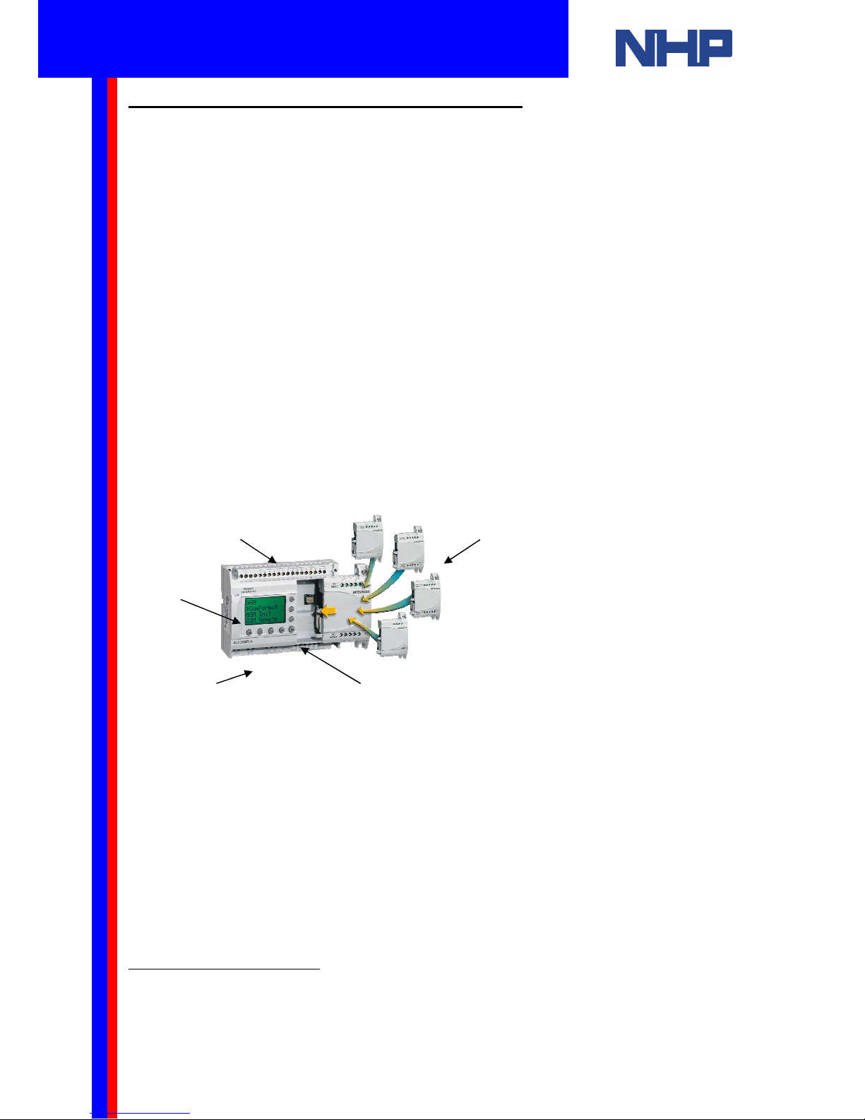
1. Important features of the Mitsubishi Alpha
The simple, user friendly Mitsubishi α series has been designed for use around your home,
office, factory... anywhere that requires flexible programmable control. Every Alpha allows
you to analyse inputs and set outputs according to your program. The Alpha displays the
status of your inputs and outputs on an LCD screen for quick verification.
Typically, the α and α2 series are suitable for use in the following automatic applications
1
:
lighting, air conditioning, irrigation, doors, gates, simple security systems, greenhouses, air
fans and more.
Some of the important features of the Mitsubishi α series programmable controllers are:
1. Compact and Robust
2. 100V AC -240V AC or 24V DC power supply
3. 1500 bytes EEPROM memory standard
4. Built-in Real Time Clock as standard
5. Sourcing or sinking type DC inputs (on 24V DC models only)
6. 0 -10V Analogue signal inputs (on 24V DC models only)
7. High current outputs
8. On-device programming through keypad and LCD screen
9. Windows based programming software, Visual Logic
10. Easy access PC programming port
The α2 series programmable controllers provide all the features of α series. Additionally the
α2 series offers:
1. Larger LCD screen with light
2. Input and Output (I/O) expansion modules
3. Greater program capacity (5000 bytes EEPROM standard)
4. Enhanced analogue control
5. Remote communication (SMS/GSM)
6. Extended operating temperature range
1
Note: The α
αα
α and α2
α2α2
α2 series programmable controller are not designed to be used in life
critical applications or applications where high reliabilities such as nuclear power
control, railway facilities, airline facilities, vehicles, combustion equipment, and
medical equipment are required. Please contact your local NHP dealer for a suitable
alternative.
5&6
Q u i c k S t a r t G u i d e
Mitsubishi Alpha / Alpha2
Programmable Controller
4
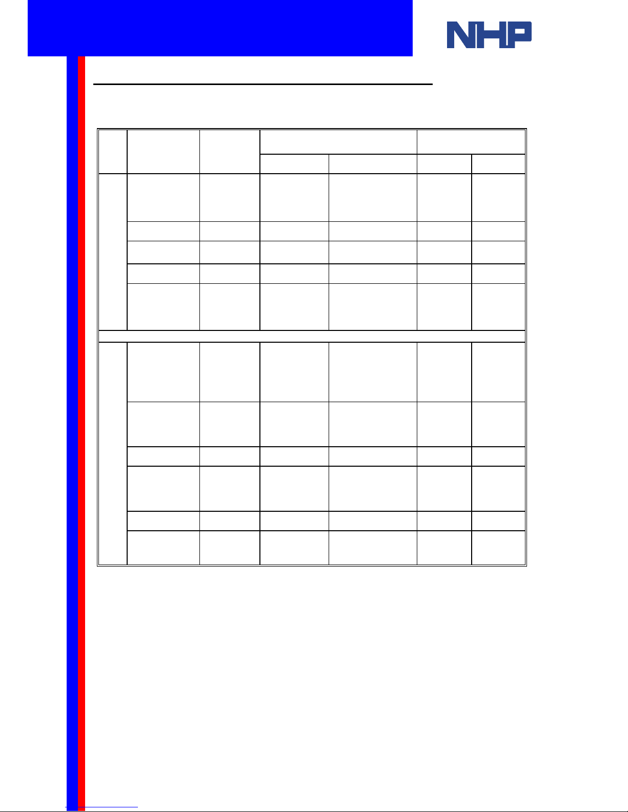
1.1 Mitsubishi Alpha models and expansion modules
Please refer to the table below for the available models of the Mitsubishi α and α2
programmable controllers:
DIGITAL INPUT DIGITAL OUTPUT
TYPE
MODEL
POWER
SUPPLY
Type Number Type Number
AL-6MR-A 100-240V AC 100-240V AC
4 Relay 2
AL-10MR-A 100-240V AC 100-240V AC
6 Relay 4
AL-10MR-D 24V DC
24V DC
Sink/Source
6 Relay 4
AL-20MR-A 100-240V AC 100-240V AC
12 Relay 8
α
AL-20MR-D 24V DC
24V DC
Sink/Source
12 Relay 8
AL2-10-MRA 100-240V AC 100-240V AC
6 Relay 4
AL2-10-MRD 24V DC
24V DC
Sink/Source
6
(you can use these
as 0-10V analog
inputs)
Relay 4
AL2-14MR-A 100-240V AC 100-240V AC
8 Relay 6
AL2-14MR-D 24V DC
24V DC
Sink/Source
8
(you can use these
as 0-10V analog
inputs)
Relay 6
AL2-24MR-A 100-240V AC 100-240V AC
15 Relay 9
α2
AL2-24MR-D 24V DC
24V DC
Sink/Source
15
(use up to 8 as 0-
10V analog inputs)
Relay 9
For the Mitsubishi α2 series programmable controllers the following expansion modules are
available to increase the number of inputs and outputs (I/O).
- AL2-4EX – Expansion Module, 4 Digital IN, 24 V DC (Sink/Source)
- AL2-4EX-A2 – Expansion Module, 4 Digital IN, 240 V AC
- AL2-4EYR – Expansion Module, 4 Digital OUT (Relay, 2A)
- AL2-4EYT – Expansion Module, 4 Digital OUT (Transistor, 1A)
- AL2-2DA – Expansion Module, 2 Analog OUT
For detailed information on a particular Mitsubishi Alpha model or expansion module please
refer to your hardware manual.
Q u i c k S t a r t G u i d e
Mitsubishi Alpha / Alpha2
Programmable Controller
5
2. How to Wire Your Alpha’s Power Supply, Inputs and Outputs
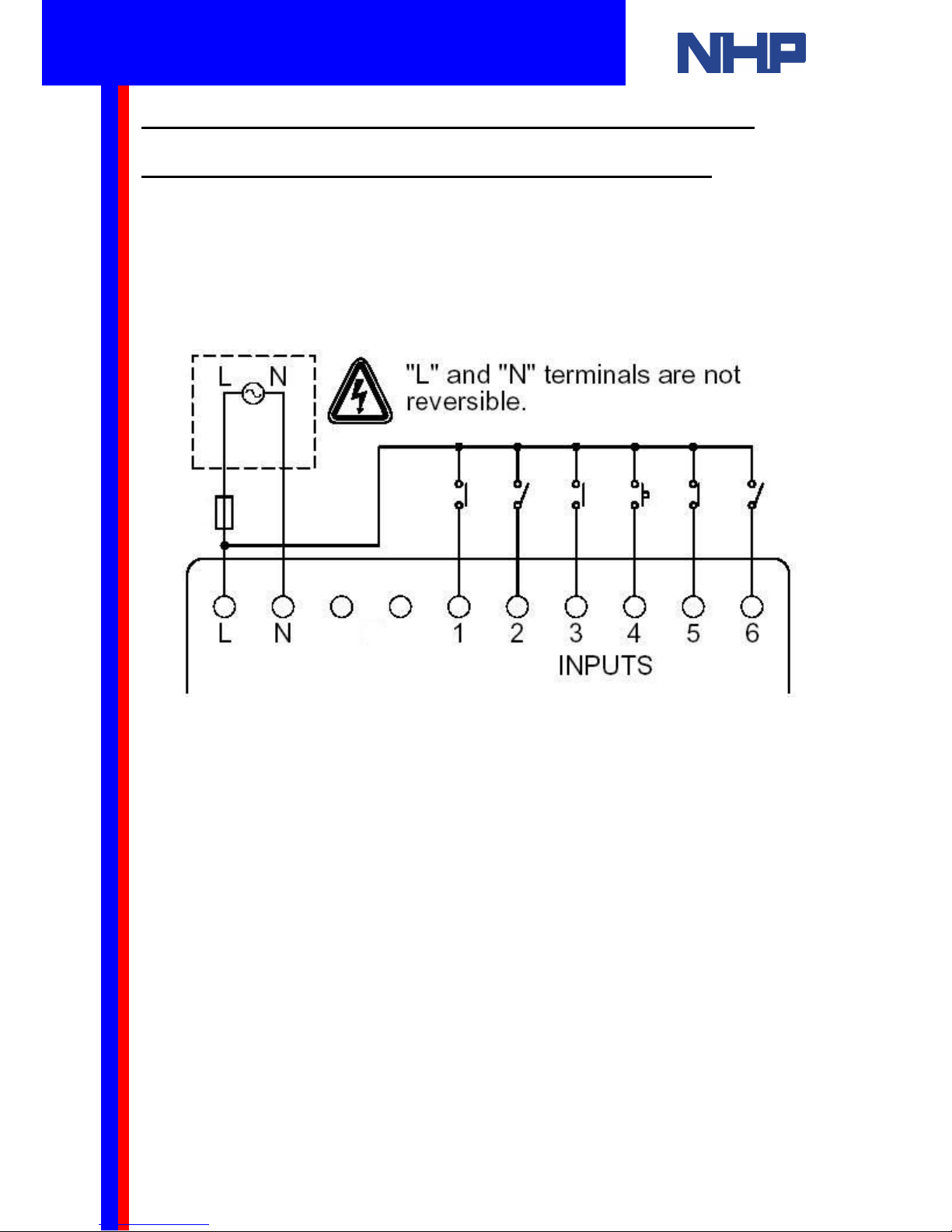
2.1. 100V AC - 240V AC Power Supply, Inputs and Outputs
When wiring AC supplies the “Live” (Active) cable should be connected to the “L” terminal and
the “Neutral” cable should be connected to the “N” terminal. Do NOT connect the “Live” wire
to the “N” terminal. Take care to follow this diagram when wiring the inputs of a 240V AC
Alpha. Inputs must be 100-240V AC.
These models cannot accept DC inputs. Also, these
models cannot accept analog inputs.
Q u i c k S t a r t G u i d e
Mitsubishi Alpha / Alpha2
Programmable Controller
6
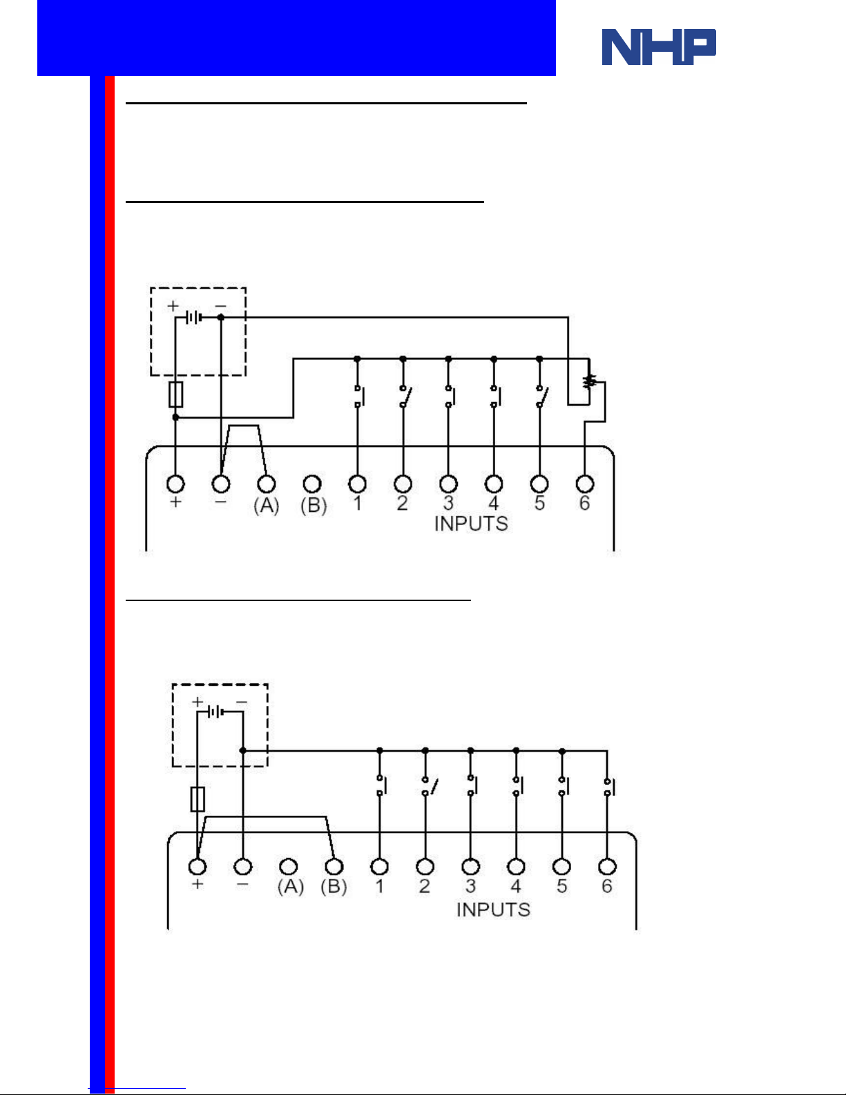
2.2 24V DC Power Supply, Inputs and Outputs
When wiring DC supplies the “positive” cable should be connected to the "+" terminal and the
negative cable should be connected to the “-” terminal. Do NOT connect the “positive” wire to
the “-” terminal. A 24V DC Alpha may be wired to use sourcing inputs or sinking inputs.
2.2.1 Wiring Sourcing DC Input Terminals
Follow this diagram for 24V DC “source” inputs (the positive terminal is common). Take
special care to wire a link from the negative terminal (-) to the A terminal. This link lets the
Alpha know that the inputs will be sourcing.
2.2.2 Wiring Sinking DC Input Terminals
Follow this diagram for 24V DC “sink” inputs (the negative terminal is common). Take special
care to wire a link from the positive terminal (+) to the B terminal.
Q u i c k S t a r t G u i d e
Mitsubishi Alpha / Alpha2
Programmable Controller

7
DC
Power
Supply
Switched
Devices
AC Power
Supply
Switched
Devices
2.3 Wiring the Output Terminals
The Mitsubishi Alpha and Alpha2 controllers use relay type outputs (these can be used for
switching AC or DC). Follow this diagram when wiring outputs to your Alpha.
Note: Please check your manual for the current rating and maximum number of
switching cycles. Typically, do not exceed 2A/point and 100,000 cycles at 2A.
Q u i c k S t a r t G u i d e
Mitsubishi Alpha / Alpha2
Programmable Controller

8
3. A Quick Introduction to Programming the Alpha
The Mitsubishi α and α2 series programmable controllers can be programmed using either:
• The Alpha’s front keypad or
• Windows based “Visual Logic” software
An Alpha program is written using function and logic blocks. Function and logic blocks
provide complex functionality with simple interconnections between them. As a function and
logic block programmer it is your task to:
1. Choose the appropriate block
2. Set the block’s parameters (where this is necessary)
3. Connect your blocks in the correct sequence for your application
Some commonly used logic blocks:
• NOT - inverts a digital signal
• AND - series connected circuit
• OR – parrallel connected circuit
Some commonly used function blocks:
• Set Reset – pulse the “set” pin to set a signal, pulse the “reset” pin to clear it.
• Delay timer - timed delay to switch signal ON or OFF
Open your Alpha’s Software manual to section 6.2 (pages 46-55). This section describes
how each input, output, logic and function block operates. Sections 6.2.7 (page 52) and 6.2.8
(page 53) are particularly useful. These sections describe the specific operation of each of the
logic and function blocks.
A program for the Mitsubishi α can contain up to 64 blocks (1500 bytes of memory).
A program for the Mitsubishi α2 can contain up to 200 blocks (5000 bytes of memory).
The task of checking the appropriateness of your blocks is made simpler with the Visual Logic
software’s simulation mode. For a tutorial and a step-by-step programming example, skip
ahead in this document to the section titled “How to write a program using your PC and Visual
Logic”.
Q u i c k S t a r t G u i d e
Mitsubishi Alpha / Alpha2
Programmable Controller

9
4. How to Program your Alpha Using the Front Keypad and LCD Screen
The α and α2 series programmable controllers can be programmed directly, using the front
keypad. It is possible to write a large program using this method. However, the amount of the
program you are able to view, while you program, is limited to the size of the LCD screen.
Hence, we advise direct programming is more useful for simple timer changes, simple
upgrades or for writing small, simple programs.
The following will guide you through programming an Alpha using the front keypad and LCD
screen. This tutorial will show you how to:
• Set the Alpha’s Time and Date using the keypad
• How to Write a Small Program using the keypad
4.1 How to Set the Alpha’s Time and Date using the Keypad
Apply power to the controller. Please consult the instructions in section 2 of this guide to
ensure this is done correctly.
Enter the menu by pressing the “ESC” and “OK” buttons simultaneously.
Use UP (▲) or DOWN (▼) to select ClockSet then press “OK”.
Press “OK” again
The second line should be flashing a date format.
Use the PLUS (+) button to select dd/mm/yyyy.
Press the DOWN (▼) button.
Use the PLUS (+) or MINUS (-) buttons to set the month.
Press the LEFT (◄)
Use the PLUS (+) or MINUS (-) buttons to set the day.
Press RIGHT (►) twice.
Use the PLUS (+) or MINUS (-) buttons to set the year.
Press the DOWN (▼) button. Now set the time using the method you learned above.
This should be in 24 hour format (eg: 11:00pm is 23:00).
The day (“Mon”, “Tues”, “Wed”) is updated from the date you set above. There is no need to
alter this.
When you are satisfied with the time and date you’ve set, press “OK”.
Now press “ESC” to return to the TopMenu.
Press “ESC” again to exit the menu. The time is now visible at the top of the screen.
ClockSet
yyyy/mm/dd
1998/09/30
14:35 Wed
TopMenu
Setup TS
ProgEdit
ClockSet
Q u i c k S t a r t G u i d e
Mitsubishi Alpha / Alpha2
Programmable Controller

10
In this section of the lesson you have learnt how to set the time and date.
You’ve been introduced to the “OK”, “ESC”, UP (▲), DOWN (▼), LEFT (◄),RIGHT (►),
PLUS (+) and MINUS (-) buttons. Also, you have learnt how to browse and navigate the
Alpha’s menus. In the following sections you will use what you’ve learnt here to write a small
program on your Alpha using the keypad and LCD screen.
The program you will write here will set output (Out 1) after the input (In 1) has been set for 5
seconds. This program will use the Alpha’s Delay function block.
4.2 How to Enter Run, Stop and Programming Mode
To enter programming mode, the controller must be stopped. A rotating bar in the top right
hand corner of the LCD screen indicates the Alpha is running.
Enter the menu by pressing the “ESC” and “OK” buttons simultaneously.
If your Alpha is running, use the UP (▲) or DOWN (▼) buttons to find STOP. Press the “OK”
button. Press “OK” again. Your Alpha should now be stopped.
When you are satisfied your Alpha is stopped, you’re ready to start programming. Use the
UP (▲) or DOWN (▼) buttons to select ProgEdit and press the “OK” button.
This will place the controller into programming mode. By default, as soon as you enter the
ProgEdit submenu, the first Input (In 01) will flash on the display.
If you wish to use Input 2 (In 02) press the PLUS (+) button. By pressing PLUS (+) or MINUS
(-) buttons you are able to use any of your Inputs (In) or Outputs (Out), also Memory (M) bits,
Key (K) bits and others. Please see your Alpha’s Programming manual for a description of
these.
01
In
16:00 Fri
O : ▪ ▪ ▪ ▪ ▪ ▪
Q u i c k S t a r t G u i d e
Mitsubishi Alpha / Alpha2
Programmable Controller

11
4.3 How to Choose a Function Block and Connect to an Input
Any function block that has an output pin can be connected to any function block that has an
input pin.
You will use Input 1 (In 01).
Press the RIGHT (►) button. Now the output pin is flashing.
Press the PLUS (+) button to add a function block.
A list will appear for you. From this list you can choose to connect your input to: a new
Function Block (AddFB) or System Outputs (if available) or existing Function Blocks that have
free input pins.
Select AddFB use the UP (▲) or DOWN (▼) buttons if necessary, and press the “OK”
button.
Press DOWN (▼) until you find the Delay function block.
Press “OK”.
A Connect message will appear on the screen, either above or below the left hand block. The
Alpha is prompting you to connect In01 to the flashing input of Delay. Press”OK”.
The Delay function block is connected to your input. Pins that have been used will show as
filled triangles (►). Pins that have not been used yet will show as open triangles (>).
01
In
01
Connect
AddFB
O01
P
01
Connect
001
01
DL
001
In
Q u i c k S t a r t G u i d e
Mitsubishi Alpha / Alpha2
Programmable Controller

12
4.4 How to Set Up a Function Block
Now you will set Delay to time for 5 seconds.
Press RIGHT (►) The block’s labels should be flashing. Press “OK”.
A menu will appear. Time Unit will be flashing. Press “OK”.
You should use 1 second as the time unit for the 5 second delay.
Press DOWN (▼) to 1 s. Press “OK”.
The Delay block can be setup as an On-delay or an Off-delay.
Press DOWN (▼) to select Setup FB. Press “OK”.
The delay you are creating will delay the output turning ON until the input has been ON for
five seconds. (A 5 second On-delay).
The output should turn OFF as soon as the input turns OFF. (No Off-delay).
Select OnDelay and Press “OK”.
Use the PLUS (+) or MINUS (-) buttons to set T = 5s and t = 0s. Press “OK”. Now Press
“ESC”. Ensure there will be no delay when the input clears (turns off) by pressing DOWN (▼)
to select OffDelay. Press “OK”. Here, use the PLUS (+) or MINUS (-) buttons to set T = 0s
and t = 0s. Press “OK”. Press “ESC” twice to return to your program.
So far you have:
1. Chosen the appropriate function block for your program and connected it to an input.
2. You have set this block’s parameters. In this case the type of delay (On Delay) and time to
delay (5 seconds).
3. In order to complete this program all you need to do is connect the block to an output.
001
DL
Q u i c k S t a r t G u i d e
Mitsubishi Alpha / Alpha2
Programmable Controller

13
4.5 How to Connect a Function Block to an Output
Press RIGHT (►) until your Delay block’s output pin is flashing.
The process here is identical to what you did earlier.
When your delay function block’s output pin is flashing press PLUS (+) to add an output.
A list will become available. From this list choose O01 (Output 1). Press “OK”. The connection
between your delay function block and Output 1 will be flashing. Press “OK” to make the
connection.
Now use the LEFT (◄) and RIGHT (►) buttons to browse through and verify your program.
When you are satisfied with the connections and setup of your program, exit from Program
edit mode by pressing “ESC”. A menu will appear. Press “OK”.
4.6 How to Disconnect a Function Block
If you’ve made a mistake with your connections it is simple to disconnect blocks.
Previously you selected the connection pin with using LEFT (◄), RIGHT (►),UP (▲) or
DOWN (▼) then pressed PLUS (+) to add a connection. Then, “OK” to make the connection.
Disconnecting a block is a similar process.
Select the connection pin using LEFT (◄), RIGHT (►),UP (▲) or DOWN (▼) then press
MINUS (-) to break the connection. Then, “OK” to accept the disconnection.
You may want to delete (remove) the block from your program.
O01
Connect
001
Q u i c k S t a r t G u i d e
Mitsubishi Alpha / Alpha2
Programmable Controller
14
4.7 How to Remove a Function Block
Use the LEFT (◄), RIGHT (►),UP (▲) or DOWN (▼) buttons to select the blocks labels.
Now press the “OK” button. You have used this menu previously to set up the time unit and
type of delay. Press DOWN (▼) three times to select Delete FB.
Press “OK”. Now press “OK” again to confirm the deletion. Or press “ESC” to cancel the
deletion.
When a function block is deleted, all connections to that function block will also be removed.
Note: For more information related to the programming of the Mitsubishi αααα and α2
α2α2
α2
programmable controllers using the front keypad, please refer to the programming
manual, supplied on the installation CD-ROM.
001
DL
Q u i c k S t a r t G u i d e
Mitsubishi Alpha / Alpha2
Programmable Controller
 Loading...