

Page 1
α
2 SIMPLE APPLICATION CONTROLLER
Page 2

α2 Simple Application Controllers
Foreword
• This manual contains text, diagrams and explanations which will guide the reader in the
correct programming and operation of the
• Before attempting to install or use the
understood.
• If in doubt at any stage of the installation of the
professional electrical engineer who is qualified and trained to local and national standards
which apply to the installation site.
• If in doubt about the operation or use of the
Mitsubishi Electric distributor.
• This manual is subject to change without notice.
α2 series controller.
α2 Series Controller this manual should be read and
α2 Series Controller always consult a
α2 Series Controller please consult the nearest
Page 3

α
2
Simple Application Controllers
α2 SIMPLE APPLICATION
CONTROLLERS
PROGRAMMING MANUAL
Manual number : JY992D97101
Manual revision : A
Date : Apr. 2002
i
Page 4

α
2
Simple Application Controllers
FAX BACK
Mitsubishi has a world wide reputation for its efforts in continually developing and pushing back
the frontiers of industrial automation. What is sometimes overlooked by the user is the care
and attention to detail that is taken with the documentation. However,to continue this process
of improvement, the comments of the Mitsubishi users are always welcomed. This page has
been designed for you,the reader,to fill in your comments and fax them back to us. We look
forward to hearing from you.
Fax numbers: Your name....................................................
Mitsubishi Electric.... .....................................................................
America (708)298-1834 Your company ..............................................
Australia (02)638 7072 .....................................................................
Germany (0 21 02)4 86-1 12 Your location: ...............................................
Spain (34)93-589-1579 .....................................................................
United Kingdom (01707)278695
Please tick the box of your choice
What condition did the manual arrive in?
Will you be using a folder to store the manual?
What do you think to the manual presentation?
Are the explanations understandable?
Which explanation was most difficult to understand: ..................................................................
....................................................................................................................................................
Are there any diagrams which are not clear?
If so,which: ..................................................................................................................................
What do you think to the manual layout?
If there one thing you would like to see improved,what is it?......................................................
....................................................................................................................................................
....................................................................................................................................................
Could you find the information you required easily using the index and/or the contents, if
possible please identify your experience: ...................................................................................
....................................................................................................................................................
....................................................................................................................................................
....................................................................................................................................................
....................................................................................................................................................
¨Good ¨Minor damage ¨Unusable
¨Yes ¨No
¨Tidy ¨Un-friendly
¨Yes ¨Not too bad ¨Unusable
¨Yes ¨No
¨Good ¨Not too bad ¨Un-helpful
Do you have any comments in general about the Mitsubishi manuals?.....................................
....................................................................................................................................................
....................................................................................................................................................
....................................................................................................................................................
....................................................................................................................................................
Thank you for taking the time to fill out this questionnaire. We hope you found both the product
and this manual easy to use.
ii
Page 5

α
2
Simple Application Controllers
Guidelines for the safety of the user and protection of α2 Simple Application
controllers
This manual provides information for the use of α2 Simple Application controllers. The manual
has been written to be used by trained and competent personnel. The definition of such a
person or persons is as follows;
a ) Any engineer who is responsible for the planning, design and construction of automatic
equipment using the product associated with this manual should be of a competent
nature, trained and qualified to the local and national standards required to fulfill that
role. These engineers should be fully aware of all aspects of safety with regards to
automated equipment.
b ) Any commissioning or service engineer must be of a competent nature, trained and
qualified to the local and national standards required to fulfill that job. These engineers
should also be trained in the use and maintenance of the completed product. This
includes being completely familiar with all associated documentation for the said product.
All maintenance should be carried out in accordance with established safety practices.
c ) All operators of the completed equipment should be trained to use that product in a safe
and co-ordinated manner in compliance to established safety practices. The operators
should also be familiar with documentation which is connected with the actual operation
of the completed equipment.
Note : the term ‘completed equipment’ refers to a third party constructed device which
contains or uses the product associated with this manual.
Notes on the symbology used in this manual
At various times through out this manual certain symbols will be used to highlight points of
information which are intended to ensure the users personal safety and protect the integrity of
equipment. Whenever any of the following symbols are encountered its associated note must
be read and understood. Each of the symbols used will now be listed with a brief description of
its meaning.
Hardware warnings
1 ) Indicates that the identified danger WILL cause physical and property damage.
2 ) Indicates that the identified danger could POSSIBLY cause physical and property
damage.
3 ) Indicates a point of further interest or further explanation.
Software warning
4 ) Indicates special care must be taken when using this element of software.
5 ) Indicates a special point which the user of the associate software element should
be aware of.
6 ) Indicates a point of interest or further explanation.
iii
Page 6

α
2
Simple Application Controllers
iv
Page 7

α
2
Simple Application Controllers
Table of Contents
Safety Guidelines ................................................................................ iii
1. Introduction ..............................................................................1-1
1.1 Special Features Display messages and Function Block data ............. 1-1
1.2 Model Name ..........................................................................................1-2
2. Function Block Programming .................................................... 2-1
2.1 Block Type and the FBD base ..............................................................2-1
2.1.1 Inputs ........................................................................................... 2-2
2.1.2 Front Panel Keys ..........................................................................2-2
2.1.3 System Memory Bits ....................................................................2-3
2.1.4 Function Blocks ............................................................................2-3
2.1.5 Outputs ........................................................................................2-4
2.1.6 Function Block Diagram (FBD) base ............................................2-4
2.2 Programming Methods ..........................................................................2-5
2.2.1 Direct Programming .....................................................................2-5
2.2.2 AL-PCS/WIN-E Programming Software Ver 2.00 ........................ 2-5
3. System Menu ............................................................................ 3-1
3.1 Menu Options Instructions ....................................................................3-1
3.2 The Stop Mode ..................................................................................... 3-1
3.2.1 Top Menu .....................................................................................3-1
3.2.2 The “Others... ...............................................................................3-3
3.3 The Run Mode Top Menu ..................................................................... 3-7
3.4 The Edit Menu ..................................................................................... 3-13
3.5 The Function Block Edit Menu ............................................................3-13
3.6 Option Screen Setup ........................................................................... 3-13
3.6.1 ProgEdit ..................................................................................... 3-13
3.6.2 Change the Language Setting ...................................................3-13
3.6.3 ClockSET ...................................................................................3-14
3.6.4 SummerTime ..............................................................................3-14
3.6.5 Password ................................................................................... 3-15
3.6.6 Serial Com ................................................................................. 3-15
3.6.7 Memory cassette ........................................................................3-16
3.7 LCD Displays ......................................................................................3-17
3.7.1 Image Table ...............................................................................3-17
3.7.2 LCD Function .............................................................................3-17
3.8 Block Items .........................................................................................3-18
3.8.1 Input Blocks ...............................................................................3-18
3.8.2 Function Blocks .......................................................................... 3-18
3.8.3 Output Blocks .............................................................................3-18
3.8.4 Connected Blocks ......................................................................3-18
v
Page 8

α
2 Series Applications Controller
4. Direct Programming .................................................................. 4-1
4.1 Block Availability ...................................................................................4-1
4.2 Connecting Blocks ................................................................................4-1
4.2.1 To connect the blocks from the left block to right block. .............. 4-1
4.2.2 To connect the blocks from the right block to left block. .............. 4-2
4.3 Disconnect Two Blocks ......................................................................... 4-2
4.4 Methods to Create a Function Block .....................................................4-3
4.4.1 New FB ........................................................................................4-3
4.4.2 AddFB .......................................................................................... 4-3
4.5 Function Block Editing ..........................................................................4-3
4.5.1 Setup Function Block ...................................................................4-3
4.5.2 Change No. (of a Function Block) ................................................ 4-3
4.5.3 Delete FB .....................................................................................4-3
4.6 Movement between Function Blocks ....................................................4-4
4.6.1 Movement Between Unconnected Blocks .................................... 4-4
4.6.2 Movement Between Connected Blocks ....................................... 4-4
4.6.3 The Jump Command .................................................................... 4-4
4.7 Using Keys as Inputs ............................................................................ 4-4
4.8 The Monitor Mode ................................................................................. 4-5
4.8.1 Monitor/Update Function Block Values ........................................4-5
4.8.2 Forcing Outputs ON/OFF ............................................................. 4-6
4.8.3 Add/Delete Function Blocks in the Monitor Mode ........................4-6
5. The Logic Function Blocks ........................................................5-1
5.1 The AND Block ..................................................................................... 5-2
5.2 The OR Block ........................................................................................ 5-3
5.3 The NOT Block ..................................................................................... 5-4
5.4 The XOR Block (Exclusive OR) ............................................................5-4
5.5 The NAND Block (Not AND) .................................................................5-5
5.6 The NOR Block (Not OR) ......................................................................5-6
6. Function Blocks ......................................................................... 6-1
6.1 Definitions ............................................................................................. 6-6
6.2 Abbreviations ........................................................................................ 6-6
6.3 Boolean block ....................................................................................... 6-7
6.4 Set/Reset Block .................................................................................... 6-9
6.5 Pulse Block .........................................................................................6-11
6.6 Alternate Block ....................................................................................6-13
6.7 Delay Block .........................................................................................6-14
6.8 One Shot Block ................................................................................... 6-16
6.9 Flicker Block ........................................................................................6-18
6.10 TimeSW Block ..................................................................................6-21
6.10.1 Setting the First Time Switch ................................................... 6-21
6.10.2 For the Date operation: ............................................................ 6-22
6.10.3 For the Weekly Operation: .......................................................6-22
6.10.4 To Enter New Time Switches ...................................................6-22
6.10.5 To Edit Time Switches ............................................................. 6-23
6.10.6 To Delete Time Switch Data .................................................... 6-23
vi
Page 9

α
2 Series Applications Controller
6.11 Counter Block ...................................................................................6-24
6.12 Up/Down Counter Block ....................................................................6-25
6.13 Compare Block ................................................................................. 6-27
6.14 OFFSET Block .................................................................................. 6-29
6.15 Display Block ....................................................................................6-32
6.15.1 Displaying Data Onscreen ....................................................... 6-32
6.15.2 Editing Data Onscreen ............................................................. 6-33
6.16 Zone Compare Block ........................................................................ 6-36
6.17 Schmitt Trigger Block ........................................................................6-38
6.18 Hour Meter Block ..............................................................................6-41
6.19 Speed Detect Block .......................................................................... 6-43
6.20 Pulse Width Modulation .................................................................... 6-48
6.21 Retentive Alternate Block ..................................................................6-50
6.22 Addition Block ................................................................................... 6-51
6.23 Subtraction Block .............................................................................. 6-52
6.24 Multiplication Block ........................................................................... 6-53
6.25 Division Block ....................................................................................6-54
6.26 Calculation Block ..............................................................................6-55
6.27 Shift Block ......................................................................................... 6-57
6.28 GSM SMS Block ............................................................................... 6-59
6.28.1 Input Signal .............................................................................. 6-61
6.28.2 Output Signal ........................................................................... 6-61
6.28.3 Word Output .............................................................................6-61
6.28.4 Short Message Service (SMS) ................................................ 6-62
6.28.5 Comment/Signal Number ......................................................... 6-62
6.28.6 Setting ......................................................................................6-62
6.28.7 Destination ...............................................................................6-62
6.28.8 SMS Setting Dialog Box ........................................................... 6-63
6.28.9 SMS Service Center ................................................................ 6-63
6.28.10 Valid Period ............................................................................ 6-63
6.28.11 Destination ............................................................................. 6-63
6.28.12 Error Messages ...................................................................... 6-64
6.29 Random One Shot Block ..................................................................6-70
6.30 Delayed One Shot Block ................................................................... 6-72
6.31 Delayed Alternate Block ....................................................................6-75
6.32 Retentive Set Reset Block ................................................................ 6-77
6.33 Control Display Manager ..................................................................6-79
6.33.1 Operation Image: ..................................................................... 6-80
6.33.2 To Set Display Manager: .......................................................... 6-81
6.34 Connect Block ................................................................................... 6-87
vii
Page 10

α
2 Series Applications Controller
7. Lets Make a Program ................................................................ 7-1
7.1 Option Settings ..................................................................................... 7-1
7.2 The Function Block Diagram .................................................................7-1
7.3 Input the Program ................................................................................. 7-2
7.3.1 Adding Function Blocks by the Left to Right method (Section 4.2.1) 7-2
7.3.2 Scroll through the Function Blocks by Number (Section 4.6.1) .... 7-3
7.3.3 Use the Jump Command (Section 4.6.3) ..................................... 7-3
7.3.4 Use the NewFB command ...........................................................7-4
7.3.5 Connect the Function Blocks from Right to Left (Section 4.2.2) .. 7-4
7.4 Set up the Function Block Parameters (Section 4.5.1) .........................7-5
7.5 Exit the Function Block Diagram board ................................................. 7-6
8. Appendix ...................................................................................8-1
8.1 Associated Manuals .............................................................................. 8-1
8.2 System Keys .........................................................................................8-2
8.3 System Bits ...........................................................................................8-2
8.4 Boolean Gates ...................................................................................... 8-3
8.5 Function Blocks .....................................................................................8-4
viii
Page 11

α
2
Simple Application Controllers
1. Introduction
The α2 Series Controllers provides supervisory control for use in the home, office, factory or
wherever you need it. The
applications:
Applications
The
α2 Series is designed to be used for automatic applications including:
- Lighting, air-conditioning or watering control
- Opening and shutting of gates
- Security systems
- Domestic systems
- Temperature control
Introduction 1
α2 Series Controllers offers flexible I/O control for varied
However, the
- Applications where high reliabilities such as nuclear power control, railway facilities,
airline facilities, vehicles, combustion equipment and medical equipment are required.
- Applications in life critical situations
Please contact a Mitsubishi distributor for more information.
α2 Series Controllers is not designed to be used in the following applications:
1.1 Special Features Display messages and Function Block data
1 ) Display messages and Function Block data
The
α2 Series can display the state of operation and the alarm on the LCD screen as a
message. The values of timers and counters can be changed in RUN mode.
- Total characters on LCD display: 12 characters x 4 lines
- Display items: Message, values (current or set) of timers and counters, analogue
values, etc.
2 ) Program Input
The user can program directly from the front panel or use the windows based
AL-PCS/WIN-E programming software Ver2.00. Pictorial representation of data is used to
connect function blocks. Please refer to the
α Software Manual.
3 ) Enhancement of clock function
The weekly and daily calendar timer function allows switch inputs that set the powerful
time dependent control capabilities.
4 ) Analog input, 0-10V/0-500
The DC input type for the
5 ) High Speed Counter, max 1kHz
The
α2 Series has two dedicated high speed counters when using AL2-4EX EI1 and EI2.
6 ) High current output
Relay output is 8A/COM in the main unit AL2-14MR-*: O01-6, AL2-24MR-D: O01-04 and
the transistor output is 1A/point in the extension module.
α2 Series accepts 0-10V signals with a resolution of 0-500.
1 - 1
Page 12

α
2
Simple Application Controllers
7 ) GSM Function
The
α2 Series Controller uses GSM to send a SMS to a mobile phone or a dedicated
E-mail account via a standard service provider.
8 ) Dedicated Protocol
Introducing a Communication Device concept in the
user to monitor, modify and enter current and set values in Function Blocks via dedicated
protocol controlled from a personal computer.
9 ) Built-in EEPROM
The built in EEPROM eliminates the need for battery backed data.
10 )Supports 6 languages
The language option under the TopMenu can be changed to display: English, German,
French, Italian, Spanish and Swedish.
11 ) LCD Screen
Enhanced LCD screen size allows the user to view data clearer and permits the
Controller to display bar graphs and other new intricate data representation items.
Introduction 1
α2 Series Controllers allowing the
α2 Series
12 )Increased Memory
The CPU memory for the new
blocks to create a program algorithm and contains a 5000 byte capacity memory on board.
This manual will describe the procedure by which the
programmed from the front panel, the functions of the keys, and the powerful function block
capabilities.
1.2 Model Name
The α2 Series Controllers can be identified using the following format:
AL2 - α2 Series Controller
** - Total number of I/O
M - Main Unit
α2 Series Controller allows a maximum of 200 function
α2 Series Controllers can be
AL2- ** M R - A/D
A - 100~240V AC
D - +24V DC
R - Relay Type output
1 - 2
Page 13
α
2
Simple Application Controllers
2. Function Block Programming
The α2 Series Controller is programmed with a user-friendly method of combining special
dedicated purpose function blocks. The task is broken down into various stages which can be
represented by a number of function blocks. Function Block Programming simplifies
application representation but ensures complete process control. The program can be
developed in very simple steps but even a complex task can be represented in this way. For
ease of use, the function blocks have been preprogrammed to perform certain tasks yet offer
flexibility to be tailored to individual requirements.
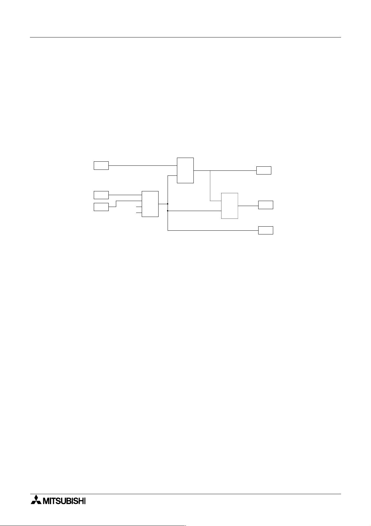
Figure 1.1: Principle of Function Block Programming
B001
I01
S
OS
C
Function Block Programming 2
O01
One Shot
I02
I03
1
2
3
4
B002
OR
I0n - Input n
O0n - Output n
OR - OR Boolean Function Block
SR - Set/Reset Function Block
OS - One Shot Function Block
The user can build a complex circuit in small easy steps by starting at the input and working
forward in a logical manner. The
α2 will gather and process information and provide the
necessary control for the application according to the system algorithm. Each individual
function block provides specific control parameters, accessible by the user, to tailor each program for complete application suitability. The function blocks are connected together to form a
circuit using the Function Block Diagram (FBD.)
2.1 Block Type and the FBD base
B003
S
SR
R
Set/Reset
O02
O03
There are seven sets of items that can be used in the function block program: Inputs, Front
Panel Keys, System Memory Bits, Logic Blocks, Function Blocks, User-defined Function
Blocks and Outputs. A brief description of each follows.
2 - 1
Page 14

α
2
Simple Application Controllers
2.1.1 Inputs
The α2 Series Controller will accept both digital (On/Off) and analog (mV value based)
electrical information through the system Inputs. Please refer to the
electrical information, wiring diagrams and input specifications. Depending on the chosen
controller there are either 14 or 24 input version types of the
are referenced to I01, I02, ..., I15.
Function Block Programming 2
α2 Hardware Manual for
α2 Series Controller. The Inputs
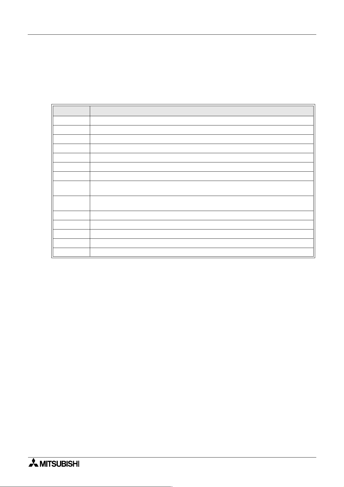
Table 2.1: Input type for the
Input Input Number Description
Signal I01 - I15 Maximum of 15 Inputs are allocated for use.
AS-i E01 - E04 Maximum of 4 AS-interface inputs are allocated for use.
Analog A01 - A08 Maximum of 8 Analog inputs are allocated for use on input I01 to I08.
Extension EI01 - EI04 Maximum of 4 Extension inputs are allocated for use.
2.1.2 Front Panel Keys
The front panel keys can enter data into the program memory, move through menus or
programs, select programming options, or be used as extra inputs when the program is
running. There are eight keys which are referenced as K01 - K08.
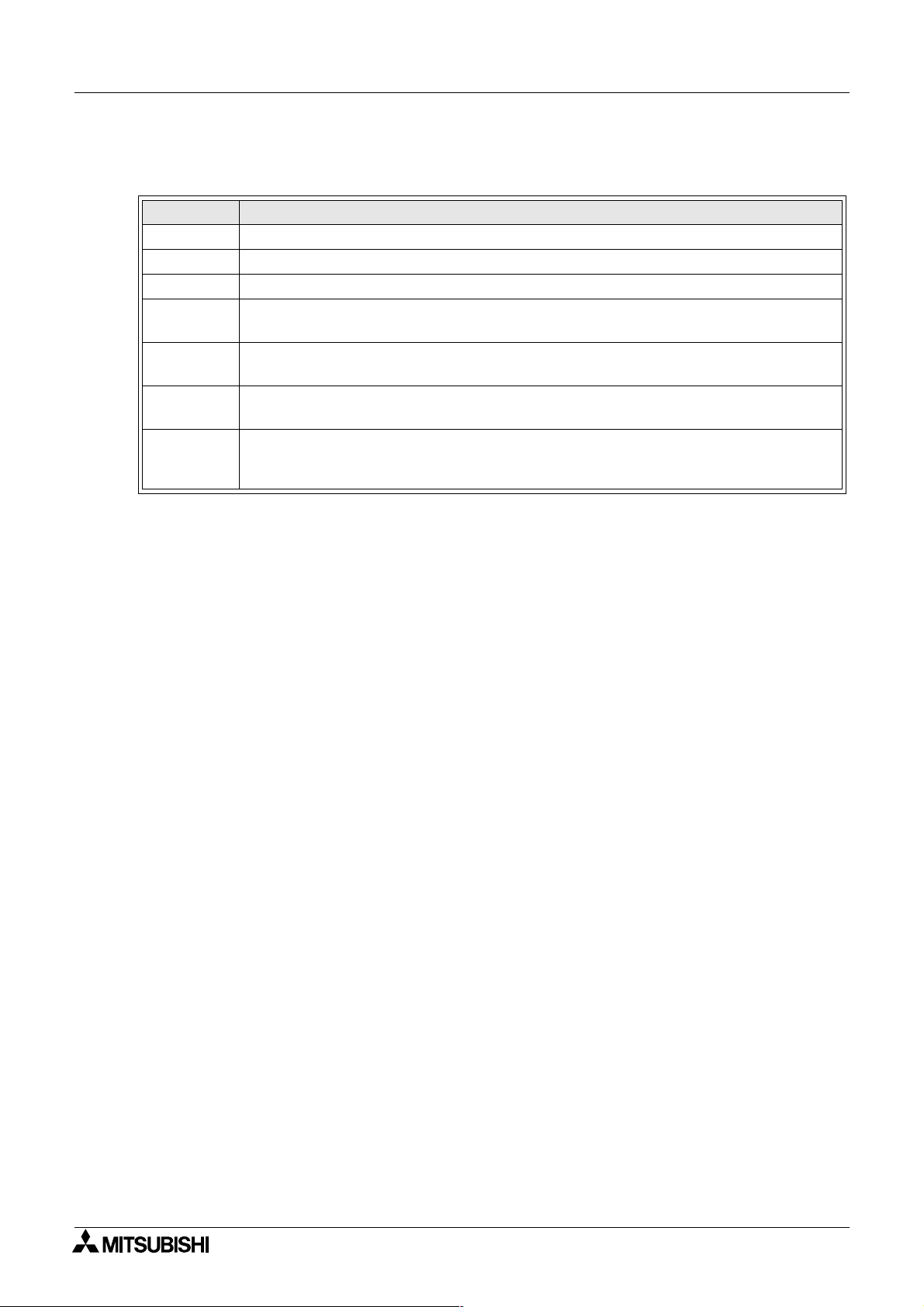
Table 2.2: Front panel keys for the
Key Name Key number Key Function
OK K01
ESC K02
“+” K03
“-” K04
( ) K05
( ) K06
( ) K07 Move to the right on the LCD display, FB program, or Jump command
( )
K08 Move to the left on the LCD display, FB program, or Jump command
α2 Series Controller
α2 Series Controller
Used to enter menu options, confirm data entry, and manually force
inputs ON/OFF in the monitor function.
Used to cancel an operation, move to a higher level screen, or to
move to a new menu.
Used to connect (or “add”) function blocks, increase Direct Set input
values or times, or move through programs or menus.
Used to disconnect function blocks, decrease Direct Set values or
times, or move through programs or menus.
Scroll up through menu options (menus, keys, FB, Inputs, Outputs,
etc.)
Scroll down through menu options (menus, keys, FB, Inputs, Outputs,
etc.)
2 - 2
Page 15
α
2
Simple Application Controllers
2.1.3 System Memory Bits
These System Memory Bits can provide predefined signals - Always On, Always Off, 0.5
second On, 0.5 second Off, or provide information about the Real Time Clock time or errors
etc. There are fourteen Memory bits that are referenced to M01, M02, ... M14.
Function Block Programming 2
Table 2.3: System Bits for the
System Bit Description
M01 Always “ON”.
M02 Always “OFF”.
M03 Alternate - 0.5 seconds “ON”, 0.5 seconds “OFF”.
M04 “ON” when Real Time Clock data error occurs.
M05 “ON” when Summer time schedule is activated.
M06 “ON” when AS-interface communication Error occurs.
M07 “ON” when communication Error caused by AS-interface power failure occurs.
M08
M09
M10 Reserved
M11 Reserved
M12 “ON” when CD (DCD) signal is turned ON (receiving CD signal from the modem.)
M13 “ON” when it is possible to access the GSM network.
M14 “ON” when the α2 series controller is accessed via GSM
“ON” when Stop mode turns to Run mode in the α2 Series. The “ON” signal acts as a
pulse output and then turns “OFF”.
“OFF” when Stop mode turns to Run mode in the α2 Series. The “OFF” signal acts as
a pulse output and then turns “ON”.
α2 Series Controller
2.1.4 Function Blocks
Programming the α2 Series Controller is based upon the combination of different function
blocks. They process the information received from the previously mentioned inputs and
control the system Outputs. They can also provide input signals or information to other
function blocks using word outputs pins. To make programming easier, the Function Blocks
have all been preprogrammed. Therefore, parameters within each function block dialog box
can be set according to the intended application. There are 38 Function Blocks available, they
are described in detail throughout Chapters 5 and 6.
2 - 3
Page 16
α
2
Simple Application Controllers
2.1.5 Outputs
Table 2.4: Outputs for the α2 Series Controller
Outputs Description
O01 - 09 Signal output
A01 - 04 AS-interface Output
EO1 - E04 Extension Output
N01
N02*1
N03*1
N04
Note: *1 When both N02 and N03 are ON and hence the back light is “ON” because N03 is
given the priority.
Function Block Programming 2
ON: Disconnected to AS-interface network
OFF: Connect to AS-interface network
ON: The back light is “OFF” in LCD.
OFF: The back light is controlled by the “Light Time” setting in Menu.
ON: The back light is “ON” in LCD.
OFF: The back light is controlled by the “Light Time” setting in Menu.
ON: The user screen is controlled by the setting of “Display Manager” with AL-PCS/
WIN-E.
OFF: The user screen is controlled by user program.
2.1.6 Function Block Diagram (FBD) base
The Function Block Diagram provides the base for which all programming actions for the α2 is
performed. Both the
FBD base contains a Title rectangle on the top, Input rectangles on the left and Output
rectangles on the right. The FBD base is also known as FBD wiring area. All the components
should be placed only within the FBD base rectangle except for the input and output signals
which can be placed in the FBD wiring area or in the Input or Output rectangles.
α2 controller and the AL-PCS/Win-E software use the FBD base. The
2 - 4
Page 17
α
2
Simple Application Controllers
2.2 Programming Methods
2.2.1 Direct Programming
Direct Programming uses the keys on the front panel to create the program and enter any
required data values. The method for Direct Programming is explained in this manual
beginning at Chapter 4.
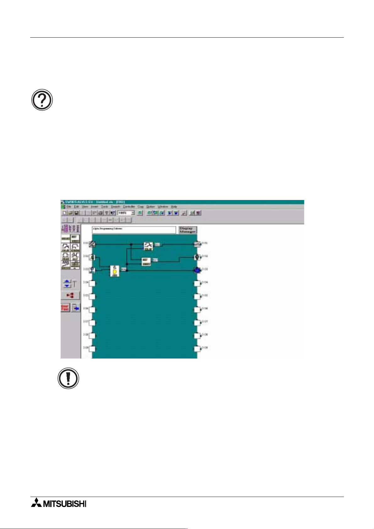
2.2.2 AL-PCS/WIN-E Programming Software Ver 2.00
This windows based software allows the user to drag and drop the desired Function Block
icons onto the FBD base and construct a program. The program is downloaded to the
controller via the AL-232CAB cable. The visual on-screen connections make the software
easy to grasp for beginners and experienced users alike. The AL-PCS/WIN-E Programming
Software is fully explained in the
Figure 2.1: AL-PCS/WIN-E Programming Software Ver 2.00
α Software Manual.
Function Block Programming 2
α2
Note: Do not simultaneously program the
programming keys and AL-PCS/WIN-E Ver 2.00 methods as this may cause harm.
α2 Series Controller from the direct
2 - 5
Page 18

α
2
Simple Application Controllers
Function Block Programming 2
MEMO
2 - 6
Page 19

α
2
Simple Application Controllers
3. System Menu
3.1 Menu Options Instructions
There are Systems Menus to help guide the user through the options available in the α2. The
TopMenu has a Run Mode that is accessed while the
accessed when the
The Edit Menu and the Function Block Edit Menu can be accessed when in either ProgEdit or
Monitor. These menus can be used to create and/or change programs steps or values.
Use the “OK” key to enter a programming option or to enter data into memory.
Set all the data on the screen before using the “OK” key to write the data to the system
memory. If there are multiple data screens in an option, enter the required data and accept
each screen with the “OK” key.
The “ESC” key will move the screen back to a higher menu option. It will cancel any data input
that has not been accepted with the “OK” key.
α2 is idle.
System Menu 3
α2 is in operation or a Stop Mode that is
Note
Use the “ESC” key to exit the option to the higher menu; at times, it will be necessary to press
the “ESC” key a number of times to move to through multiple programming layers.
3.2 The Stop Mode
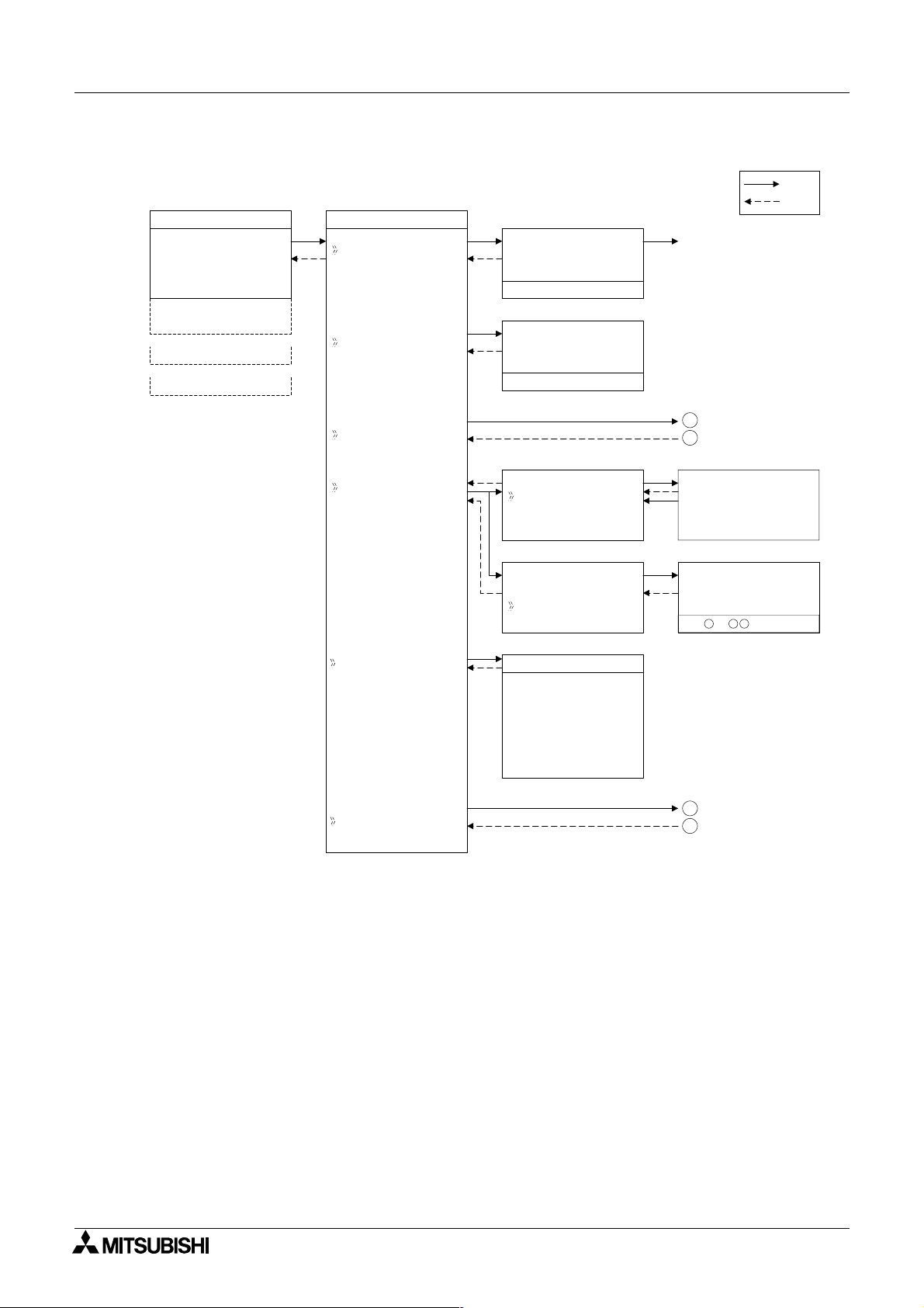
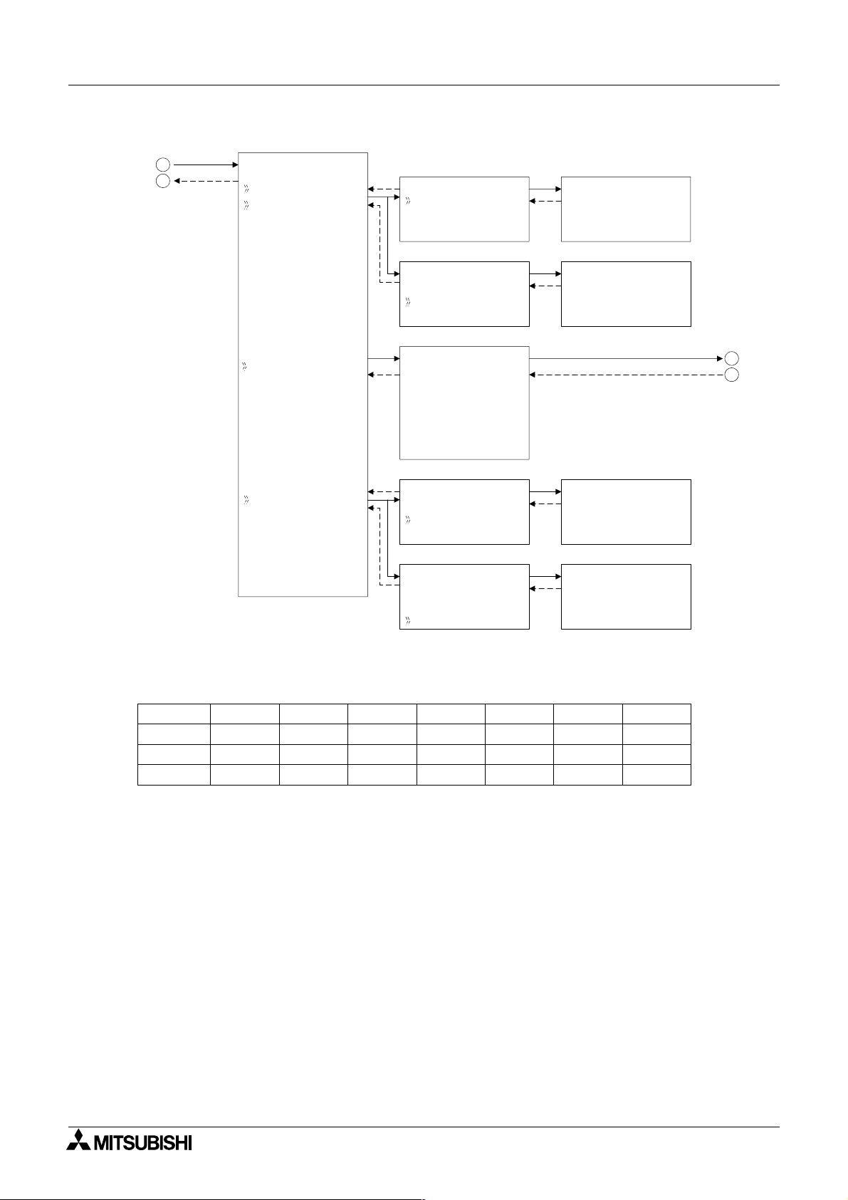
3.2.1 Top Menu
When the α2 is first turned On, the Input/Output Image Table will appear. Press the “OK” and
“ESC” keys simultaneously to move to the TopMenu.
(If the TopMenu cannot be accessed the Menu Key has been set to “Not Use”),
• Run:
Places the controller in Run mode.
•Setup TS:
Provides a simple method to edit Time Switches from the Top Menu (only selectable if a
TSm function block has been chosen.)
• ProgEdit:
Allows program editing/creation on the display using the front panel keys. The current
memory will be overwritten as changes are made to the program. Programs can be saved
on an AL2-EEPROM-2 memory cassette or in the AL-PCS/WIN-E software Version 2.0 or
above.
• ClockSet:
Set the Real Time Clock or input a daily clock adjustment.
• LANGUAGE:
Choose from 6 onscreen languages: English, German, French, Italian, Spanish, or
Swedish.
• Others...
3 - 1
Page 20
α
2
Simple Application Controllers
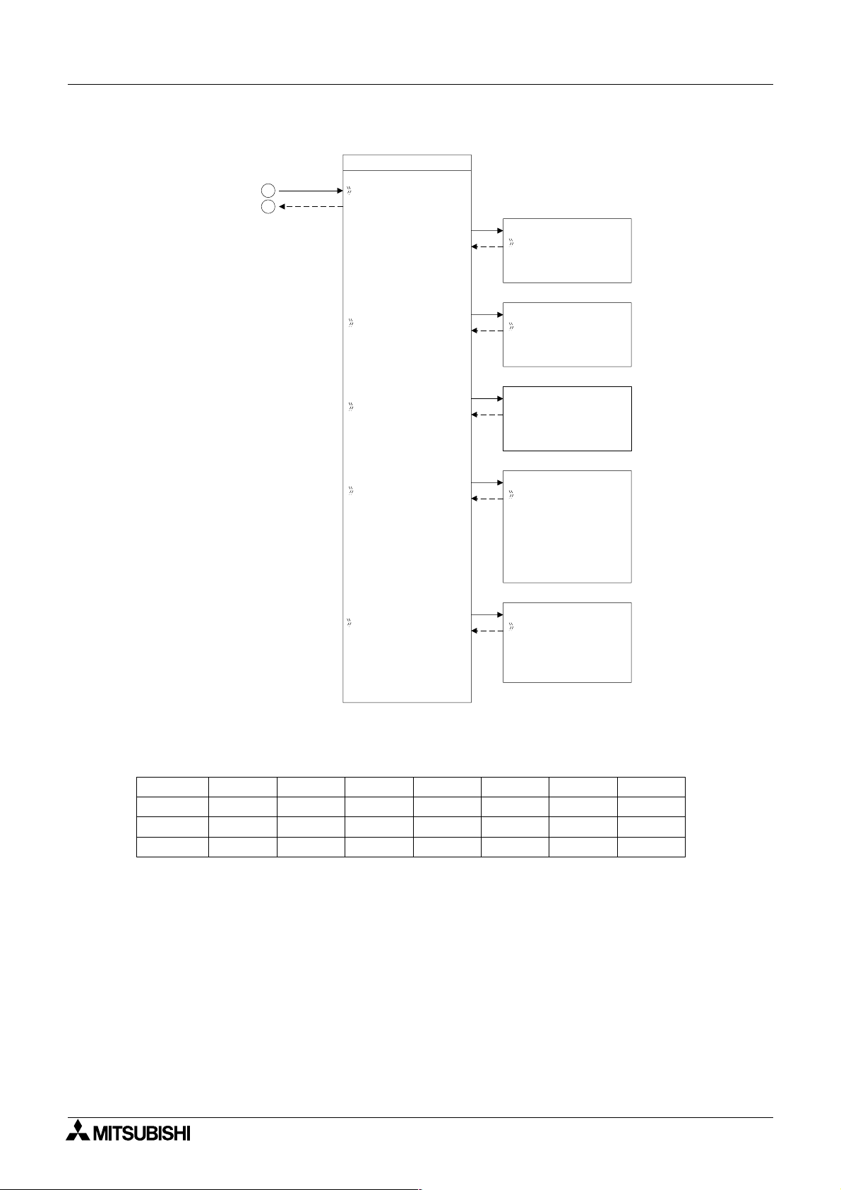
Figure 3.1: TopMenu in Stop Mode operation
10: 19 Fr i
•2••5 • •9
I:
•1••••5
O: 1• • 4 • • 8•
E:1• •4
A: •23
EI : • •41
EO : 2 3 ••
•
TopMenu
Run
Se t upTS
Run / S t op
OK o r ESC
Se t up
Stop
NoDa t a
→
Run
ST
System Menu 3
OK
ESC
Run Mode
ProgEd i t
Cl ockSet
LANGUAGE
Ot he r s
Cl ockSe t
Cl ockSet
Co r r ec t
Cl ockSe t
Cl ockSet
Co r r ec t
LANGUAGE
Eng l i s h
Ge r man
French
Italian
Spani sh
e
Sw d i s h
1
2
Cl ockSe t
dd/mm/ yyyy
30/ 11 / 2001
10: 45 Fr i
Co r r e c t
•s/d
3
4
3 - 2
Page 21

α
2
Simple Application Controllers
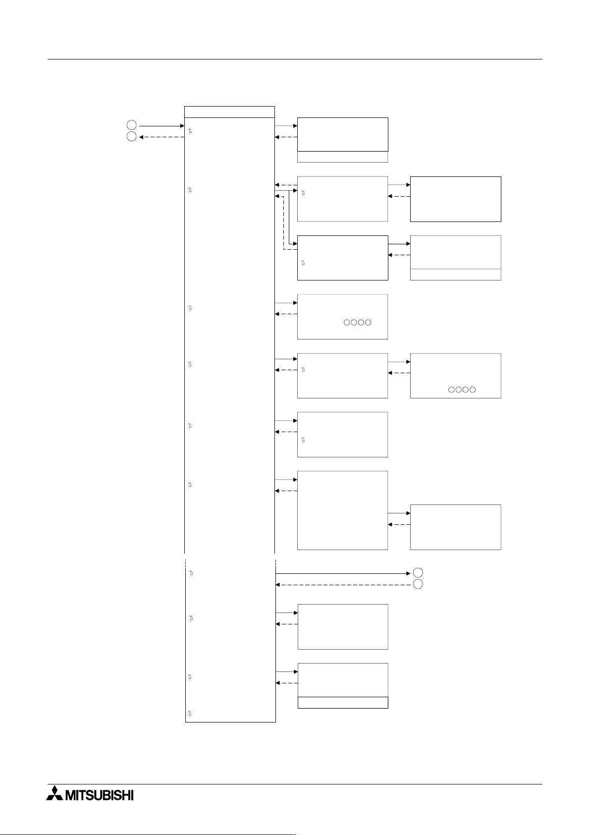
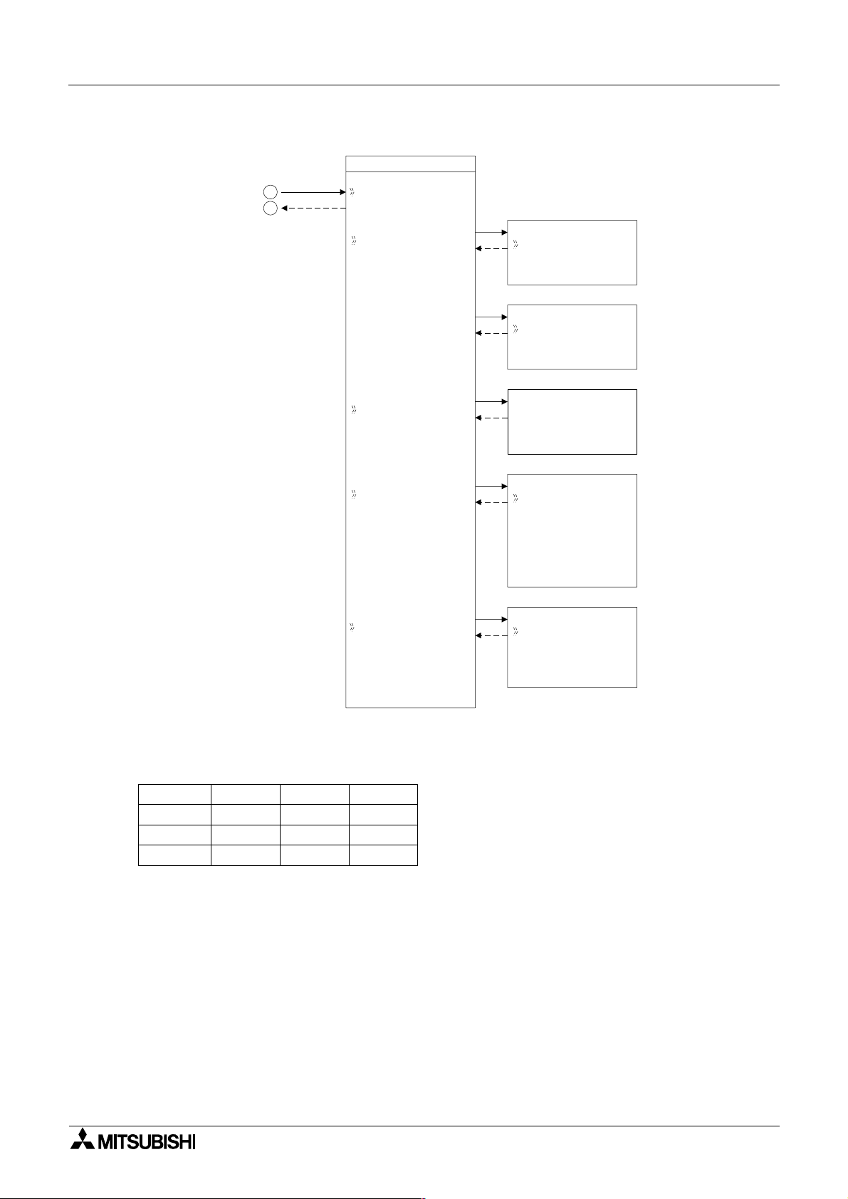
3.2.2 The “Others...
• Version:
Displays CPU Version of the
• Scan Time:
Monitor the Current, Maximum, or Minimum program scan times. Upon controller reset
current, Maximum and Minimum values for scan times are reset to 0.
• Password:
Restrict entry to the ProgEdit and Monitor mode with a four digit password.
• DispPass:
Set up to three Passwords for Display function blocks.
• Menu Key:
Two settings are possible, “Not Use” or “OK + ESC”. “Not Use” is designed so that
unauthorised people cannot access the
setting is selected, simultaneously depress the “OK” and the “ESC” keys to access the Top
Menu.
• Summertime:
Choose the preferred daylight savings time: Cancel, Manual On, Date Type, UK type, US
type, or EU type.
• Serial Com:
Choose the type of communication to be used for the right hand side serial communication
port - Not Use, Modem, GSM or Other Com.
• Light Time:
Set the backlight off delay time.
• ProgClear:
Completely clears the system memory including Password protected programs. Only the
active memory is cleared, i.e. if a memory cassette is installed, the memory cassette program will be erased but the controller memory will be retained.
• ProgTran. (only appears if a cassette is installed):
Verify,
Cassette à (the cassette writes to the α2), Cassette ß(the cassette reads
from the α2), and ProtectSW are the options available.
System Menu 3
α2 Series Controller.
α2 Top Menu in Run mode. If the “OK + ESC” key
3 - 3
Page 22
α
2
Simple Application Controllers
Figure 3.2: Others Menu in Stop Mode operation
3
4
System Menu 3
Others...
Ve r s i on
Ve r s i on
Ve r * . * *
ScanT i me
Pas swo r d
Di spPass
Me n u K e y
ScanT i me
Mo n i t o r
Res e t
ScanT i me
Mo n i t o r
Res e t
Se t u p
Pas swo r d
Di spPass
Leve l 1
Leve l 2
Leve l 3
MenuKey
No
Use
ON+
ESC
Key
ScanT i me
Cu r . 0ms
Ma x .
Mi n
Re s e t
ScanT i me
OK o r ESC
Se t up
Di spPass
Leve l 1
12ms
0ms
Summe r T ime
Se r i a l Com
LightTime
Progcl ear
ProgTran
Summe r T ime
Can c e l
Ma n u a l On
Da t aTy p e
UK T y p e
US T y p e
EU T y p e
Se t up
LightTime
2m
Pr ogCl ea r
OK o r E SC
Summe r T ime
31/ 03
~30 / 10
+60mi n
5
6
3 - 4
Page 23
α
2
Simple Application Controllers
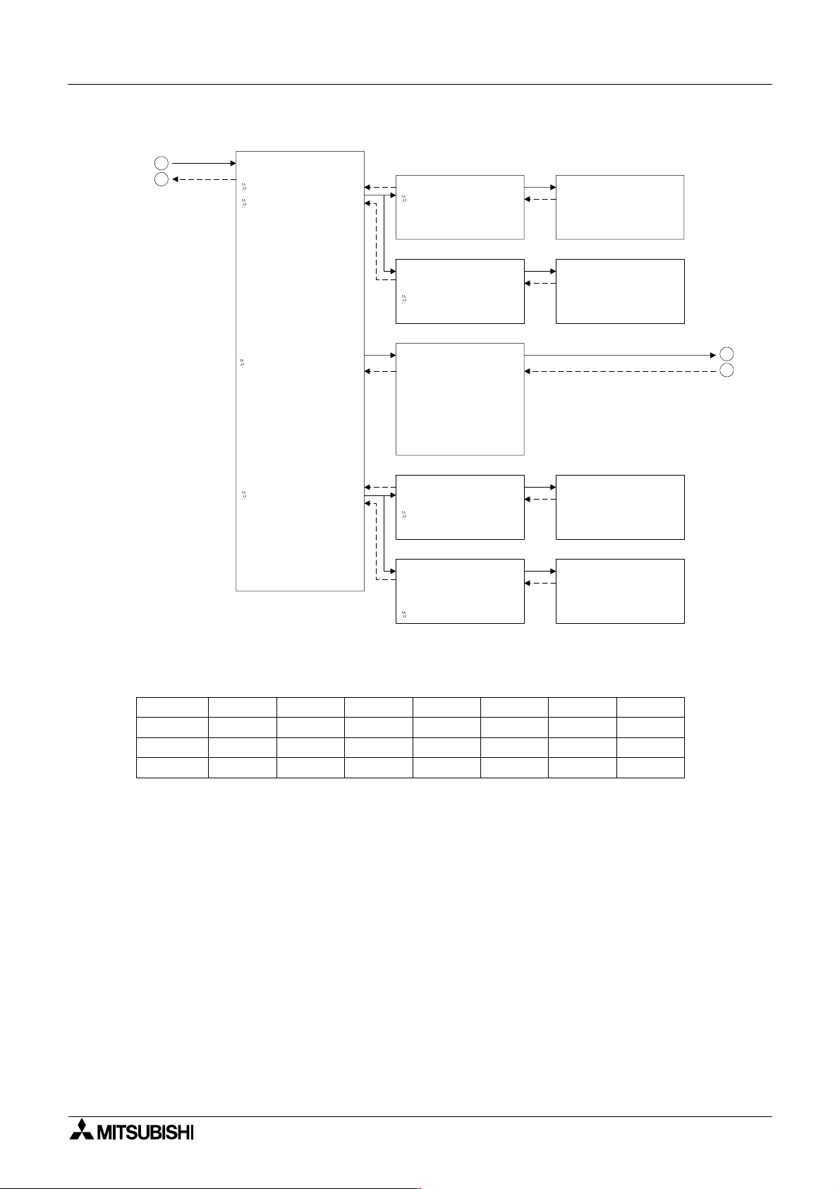
Figure 3.3: Serial Com in Stop Mode operation
System Menu 3
5
6
Se r i a l Com
No t Us e
Modem
GSM
Ot he rCom
ModemIn i t
Command
De l y T i me
a
ModemIn i t
Command
De l y T i mea
GSM
Comf o rma t
GSM I n i t
GS Re mo t e
M
P NCode
I
Se t SMS
GSMStatus
Ot he rCom Ot he rCom
Comf o rma t *
Stat i onNo
Li nkBl ock
Ot he rCom
Comf o rma t *
Stat i onNo
Li nkBl ock
ModemIn i t01
Command
[]
yz{ | } ! "#$
ModemIn i t
De l y T i mea
0s
Stat i onNo
No . 0
Ot he rCom
Li nkBl ock
0.
7
8
Figure 3.4: Communication Format in Stop Mode Operation
* Comformat
Datalengt h
Parity
Stopbit
Baudrate
8 bits
None
1 bit
300 bps 600 bps 1200 bps
7 bits
Odd
2 bits
---
Even
---
---
---
---
2400 bps
---
---
---
4800 bps
---
---
---
9600 bps
---
---
---
19200 bps
3 - 5
Page 24
α
2
Simple Application Controllers
Figure 3.5: GSM Menu in Stop Mode operation
System Menu 3
GSM
7
8
Comf o rma t *
GSM I n i t
M
GS Re mo t e
I
P NCode
Se t SMS
GSM I n i t
Commnd
De l ay T i me
M
GS Re mo t e
Fo r b i t
Pe rmi t
PI NCode
Se t up
[****]
Se t SMS
SMSC1
SMSC2
DA1
DA2
DA3
VP
GSMStatus
GSMStatus
Status
CMEE r r o r
CMSE r r o r
SigSei ng
Figure 3.6: Communication Format in Stop Mode operation
* Comformat
Datalengt h
Parity
Stopbit
Baudrate
8 bits
None
1 bit
300 bps 600 bps 1200 bps
7 bits
Odd
2 bits
---
Even
---
---
---
---
2400 bps
---
---
---
4800 bps
---
---
---
9600 bps
---
---
---
19200 bps
3 - 6
Page 25
α
2
Simple Application Controllers
System Menu 3
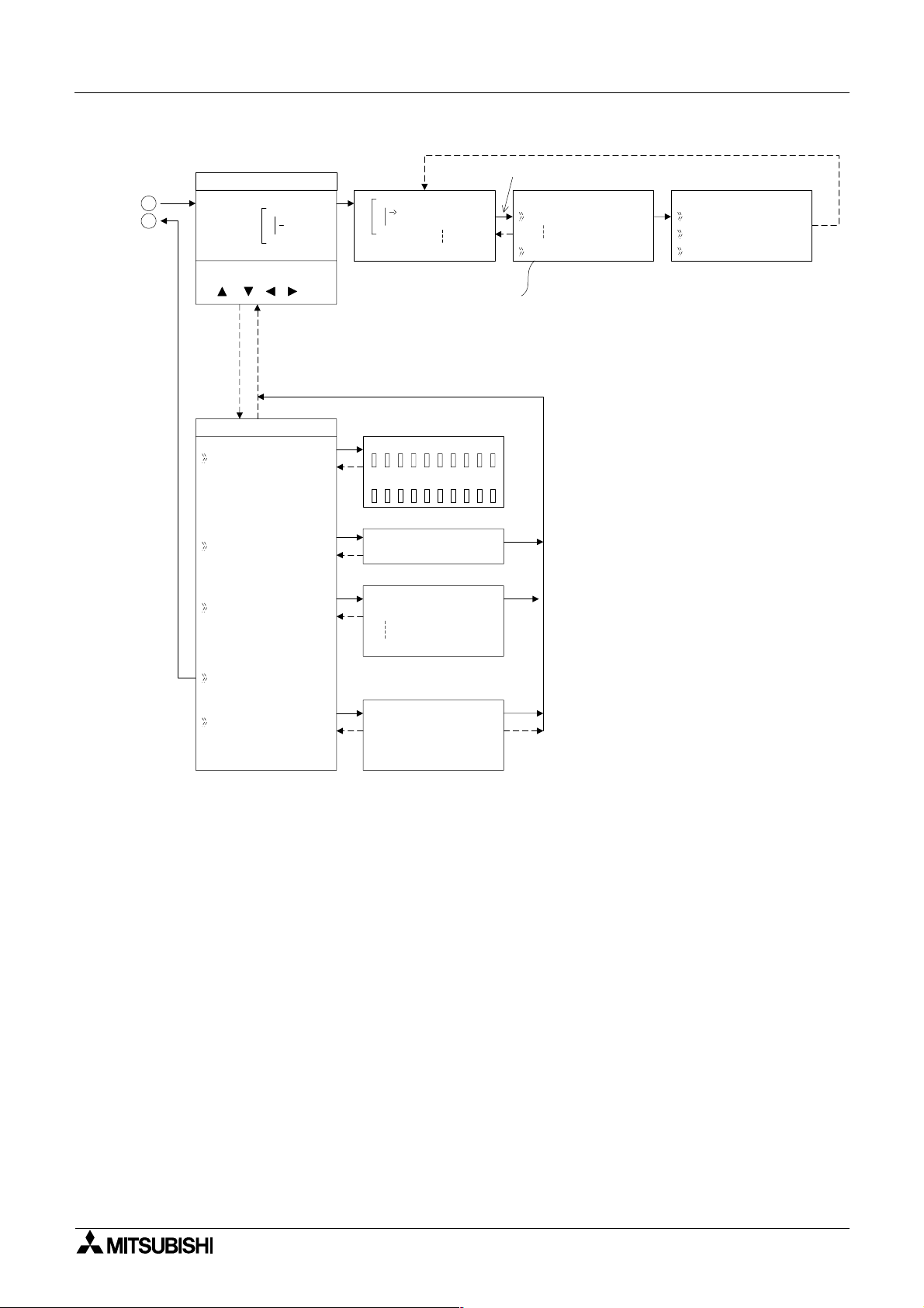
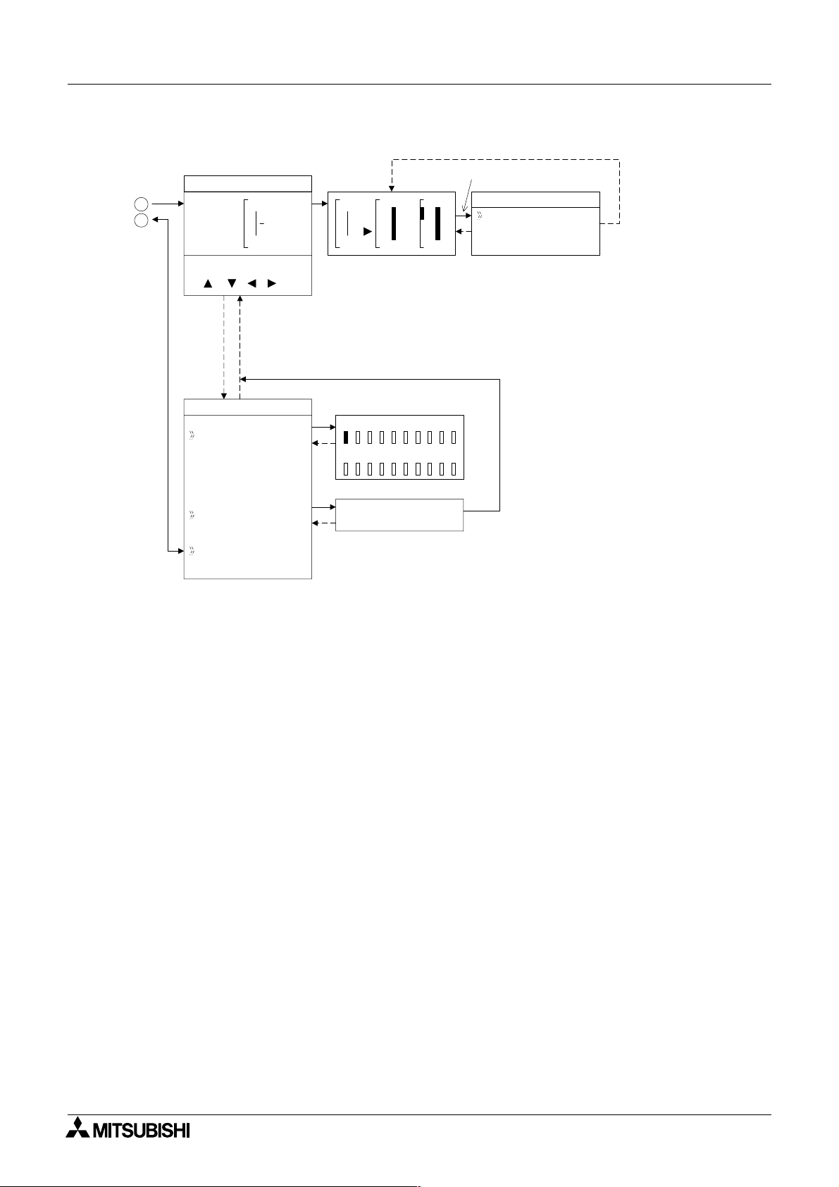
Pr ogr amScr een
1
2
(OK, ESC, +, -,
, , , )
Edi tMenu
ProgSi ze
Jump
NewFB
01
In
01
Add FB
O 01
Connect EO 04
Bl ock 0FB
Memo r y 0%
Jump
MIOKEANEIEOB
FBSe l ec t
AND
Adding Function Blocks
FBSe l ec t
AND
De l ay edA
(+) or (-) Skips to
the next topic
upFB
ter
*1
*3
FBPa r ame
Se t
ChangeN*2o
L
*1
Function Block Specific
*2
Changes Function Block Number
*3
Deletes Functi on Block from
FBD
De l e t eFB
De l ay edA
Ex i t
Mn e mo n i c
M0 1 -
3.3 The Run Mode Top Menu
When the α2 program is running, the LCD defaults to the Image Table screen. According to
the Menu Key setting, proceed to the Stop Mode of the Top Menu by using the “OK” and the
“ESC” keys or reset the controller by powering down.
• Stop:
Takes the
•Setup TS:
Provides a simple method to edit Time Switches from the Top Menu.
• Monitor:
Monitor the program settings while in the Run mode and perform limited editing to FB
parameters. The existing programming steps cannot be modified.
•ClockSet:
Set the Real Time Clock or input a daily clock adjustment.
• LANGUAGE:
Choose the on-screen language from English, German, French, Italian, Spanish, or
Swedish.
•Others
α2 out of Run mode.
L
3 - 7
Page 26
α
2
Simple Application Controllers
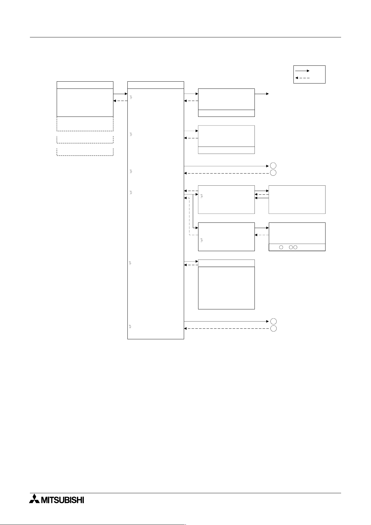
Figure 3.8: TopMenu in Run Mode Operation
10: 19 Fr i
I :•2••5 ••9
•1••••5
O: 1• • 4 • • 8•
E:1• •4
A: •23
EI : • •41
EO : 2 3 ••
•
TopMenu
Stop
Se t upTS
Run / S t op
→
Run
Stop
OK o r ESC
Se t up
TS
NoDa t a
System Menu 3
OK
ESC
Stop Mode
Mo n i t o r
Cl ockSet
LANGUAGE
Others
Cl ockSe t
Cl ockSet
Co r r ec t
Cl ockSe t
Cl ockSet
Co r r ec t
LANGUAGE
Eng l i s h
Ge r man
French
Italian
Spani sh
e
Sw d i s h
1
2
Cl ockSe t
dd/mm/ yyyy
30/ 11 / 2001
10: 45 Fr i
Co r r e c t
•s/d
3
4
3 - 8
Page 27
α
2
Simple Application Controllers
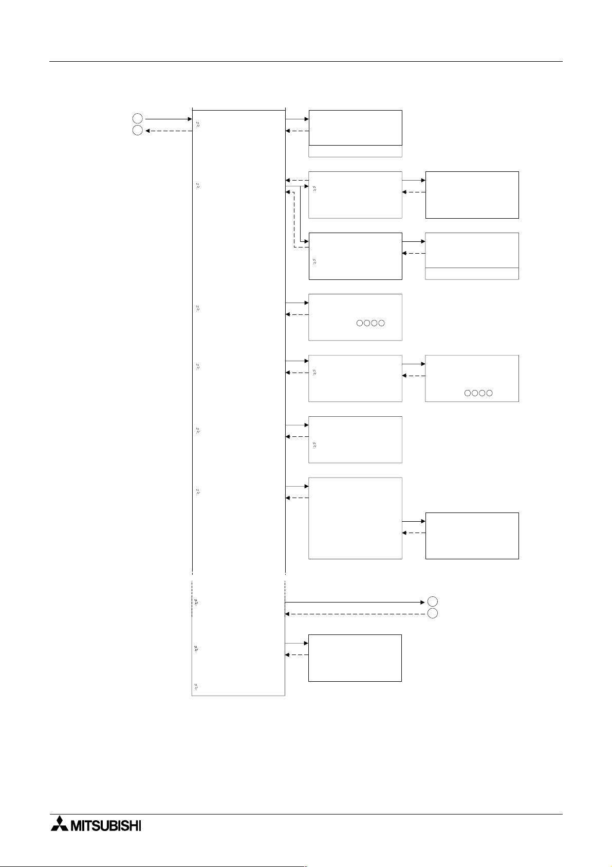
Figure 3.9: Others Menu in Run Mode operation
System Menu 3
3
4
Ve r s i on
ScanT i me
Pas swo r d
Di spPass
Ve r s i on
Ve r * . * *
ScanT i me
Mo n i t o r
Res e t
ScanT i me
Mo n i t o r
Res e t
Se t up
Pas swo r d
Di spPass
Leve l 1
Leve l 2
Leve l 3
ScanT i me
Cu r . 0ms
Ma x .
Mi n
Res e t
ScanT i me
OK o r ESC
Se t up
Di spPass
Leve l 1
12ms
0ms
MenuKey
Summer T i me
Se r i a l Com
LightTime
Pr ogTr an
MenuKey
No
Use
ON+
ESC
Key
Summer T i me
Can c e l
Ma n u a l On
Da t aTy pe
UK T y p e
US T y p e
EU T y p e
Se t up
LightTime
2m
Summer T i me
31/ 03
~30 / 10
+60mi n
5
6
3 - 9
Page 28
α
2
Simple Application Controllers
Figure 3.10: Serial Com in Run Mode operation
System Menu 3
5
6
Se r i a l Com
No t Us e
Modem
GSM
Ot he rCom
ModemIn i t
Command
De l ay
ModemIn i t
Command
GSM
Comf o rma t
GSM I n i t
GS Re mo t e
P NCode
Se t SMS
GSMStatus
Ot he rCom Ot he rCom
Comf o rma t *
Stat i onNo
Li nkBl ock
Ot he rCom
Comf o rma t *
Stat i onNo
Li nkBl ock
Time
TimeDe l ay
M
I
ModemIn i t01
Command
[]
yz{ | } ! "#$
ModemIn i t
TimeDe l ay
0s
Stat i onNo
No . 0
Ot he rCom
Li nkBl ock
0.
7
8
Figure 3.11: Communication Format in Run Mode Operation
* Comformat
Datalengt h
Parity
Stopbit
Baudrate
8 bits
None
1 bit
7 bits
Odd
2 bits
---
Even
---
---
---
---
2400 bps 4800 bps 9600 bps 19200 bps300 bps 600 bps 1200 bps
---
---
---
---
---
---
---
---
---
3 - 10
Page 29
α
2
Simple Application Controllers
Figure 3.12: GSM Menu in Run Mode operation
System Menu 3
GSM
7
8
Comf o rma t *
GSM I n i t
M
GS Re mo t e
I
P NCode
Se t SMS
GSM I n i t
m
Com and
De l ay T i me
GSR emo t e
Fo r b i t
Pe rmi t
PI NCode
Se t up
[****]
Se t SMS
SMSC1
SMSC2
DA1
DA2
DA3
VP
GSMStatus
GSMStatus
Status
CMEE r r o r
CMSE r r o r
SigSt ing
Figure 3.13: Communication Format in Run Mode operation
* Comformat
Datalengt h
Parity
Stopbit
Baudrate
8 bits
None
1 bit
9600 bps
7 bits
Odd
2 bits
19200 bps
---
Even
---
---
r
3 - 11
Page 30
α
2
Simple Application Controllers
Figure 3.14: Monitor Screen in Run Mode.
System Menu 3
Moni t o r Sc reen
1
2
(OK, ESC, +, -,
, , , )
Edi tMenu
ProgSi ze
Jump
Ex i t
01
B002
B003
In
Bl ack 4FB
Memo r y 1%
Jump
MIOKEANEIEOB
01
In
=S
003
P- I
RSR
Setti ngs for Function Blocks
02
Out
FBSe t t i n
-
Se t
*1
Individual for each Function Block.
g
up
3 - 12
Page 31

α
2
Simple Application Controllers
3.4 The Edit Menu
The Edit Menu can be entered when the α2 is in the ProgEdit or Monitor main programming
screen. If entering options or connecting FBs, these procedures have to be finished or
canceled before the Edit Menu can be entered. Press the “ESC” key at any place in the main
programming screen to enter the Edit Menu.
• ProgSize:
Shows the numbers of FBs used and percentage of program memory used.
• Jump:
Leads to a screen that shows available places to go in the program. “M” - system bits; “I” system Inputs; “O” - System Outputs; “K” - Keys (1-8); “E” - ASi Inputs; “A” - ASi Outputs;
“N” - Control bits; “EI” - External Board inputs; “EO” - External Board outputs; and “B” Function Blocks existing in the program. Choose the desired block with the arrow keys
and press the “OK” key to jump to that spot in the program.
• New FB:
Create a new Function Block from one of the available FBs.
• Exit: Exits to the Top Menu.
• Mnemonic:
Gives a mnemonic display of the current programming rung. Enter the programming
mode by pressing the “OK” key or return to the Edit Menu using the “ESC” key. (Not
available in Monitor Mode).
System Menu 3
3.5 The Function Block Edit Menu
The Function Block Edit Menu can be entered only while in the ProgEdit or Monitor mode.
Move to the Function Block to edit and press the “OK” key when the Function Block number is
flashing.
• Setup FB:
Optimise variables in the Function Blocks for your application. See Chapter 6 for more
details on each Function Block’s Options. The logic functions in Chapter 5 do not have
Setup Options.
• Change No: Change the Function Block Number
• Delete FB: Delete Selected Function Block
3.6 Option Screen Setup
Various options have been provided for ease of use or for safety purposes. Please set as your
needs require. All of the options in this section can be accessed from either the Run or the
Stop Menu.
3.6.1 ProgEdit
Refer to the Direct programming chapter 4 for detailed combinations of key presses to be able
to program the
3.6.2 Change the Language Setting
α2 Series Controller.
1 ) Turn the α2 On.
2 ) Press the “OK” and “ESC” button to go to the Top Menu or reset the controller.
3 ) Scroll to the “LANGUAGE” option and press the “OK” key. The spelling for “LANGUAGE”
does not change.
4 ) Scroll to the desired language and press the “OK” key. The languages available are
English, German, French, Italian, Spanish, and Swedish.
5 ) Use the “ESC” key to exit to the Topmenu.
3 - 13
Page 32

α
2
Simple Application Controllers
3.6.3 ClockSET
To set the Clock:
1 ) From the TopMenu, scroll to “ClockSet” and press the “OK” key.
2 ) From the options that appear, choose “ClockSet” and press the “OK” key.
3 ) Use the arrow keys to move an area that needs to be changed.
4 ) Adjust with the “+” or “-” keys.
5 ) Repeat steps 3-4 until ALL changes have been accomplished.
6 ) Press the “OK” key to accept all the changes.
7 ) Press the “ESC” key to return to the Top Menu having discarded the clockset options.
To set the daily correction:
1 ) From the TopMenu, scroll to “ClockSet” and press the “OK” key.
2 ) From the options that appear, choose “Correct” and press the “OK” key.
3 ) Set the daily correction time with the “+” or “-” keys.
4 ) Press the “OK” key to accept the value and press the “ESC” key to return to the Top Menu.
Note: The date setting can be displayed as yyyy/mm/dd, dd/mm/yyyy, or mm/dd/yyyy
by manipulating the “+” and “-” keys. The day of the week will update automatically as
the date is changed.
System Menu 3
3.6.4 SummerTime
The Summertime menu will display six choices when entered.
Cancel - Turns off the Summertime clock setting.
Manual On - Moves the clock one hour ahead immediately and will remain ON until cancelled.
Date Type - Set the On date, Off date, and Time adjustment.
UK Type - Last Sunday of March to the last Sunday of October.
US Type - First Sunday of April to the last Sunday of October.
EU Type - Last Sunday of March to the last Sunday of October.
The time changes for the UK type take place at 1:00 AM in the Spring and 2:00 AM in the
Autumn. Time changes in the EU setting take place at 2:00 AM in the Spring and 3:00 AM in
the Autumn. The date settings are equivalent.
If the display time has been adjusted for the Summertime setting, an “s” will precede hour
number on the screen.
How to Set the Summertime Setting:
1 ) Select “Others” from the Top Menu.
2 ) Select “Summertime”.
3 ) Scroll to the desired setting (see above for information on settings).
4 ) Press the “OK” key to accept.
5 ) If the display time has been adjusted, an “s” will precede hour number on the screen. If
the date is outside of the adjustment range, no visible sign will appear.
3 - 14
Page 33

α
2
Simple Application Controllers
3.6.5 Password
The password consists of four digits and will prohibit entry into the ProgEdit, Monitor, Disp
Pass and Serial Com modes only. All other menu options can be accessed when a Password
is used.
To Enter a Password:
1 ) Select “Other” Menu Option.
2 ) Select “Password” from the “Other” Menu Options
3 ) Use the “+” and “-” keys to enter the desired password.
4 ) Press the “OK” key to accept and activate the password.
5 ) A key symbol will now be displayed at the top of the
To Cancel a Password:
1 ) Select the “Other” Menu Option.
2 ) Select “Password” from the “Other” Menu Options. “Cancel Password” should appear on
the top of the screen.
3 ) Use the “+” and “-” keys to enter the current password.
4 ) Press the “OK” key to accept and deactivate the password.
5 ) The key symbol will be removed from the
System Menu 3
α2 display.
α2 display.
Note 1: A Password protected program in an AL2-EEPROM-2 Cassette can be run from and
be downloaded into the main body of the controller.
Note 2: A controller containing a Password protected program can accept or transfer
programs to an AL2-EEPROM-2.
Note 3: The Password can also be set/deleted from the AL-PCS/WIN-E software or deleted by
the “PROGCLEAR” command.
3.6.6 Serial Com
The modem function capability of the α2 allows remote monitoring via a PC and program
upload/download. The communication must take place using the Visual Logic Software (VLS)
and the communication must be initiated accordingly. (The modem connected to the
initialised upon the
available).
Command - Enter the AT command for the modem to be connected to the controller.
Reference the Modem User manual for details on that unit’s AT command. Choose the first
letter or symbol by using the ( ) and ( ) arrows. When the symbol is showing in the
command line, use the
symbols and accept the whole string with the “OK” key when finished inputting the data.
(There is no need to accept each letter with the “OK” key).
α2 is
α2 start-up. Dialing options from a command or specific conditions are not
( ) and ( ) arrows to move to adjoining spaces. Enter up to 64 letters/
Delay - The Delay function sets the length of time the α2 will wait after entering the Run mode
before turning on the modem. Choose a value of 0 - 10 seconds using the “+” or “-” keys. The
modem connected to the Personal Computer with the VLS software must be set ON prior to
the
α2 modem turning on.
The GSM function allows a SMS (Short Message Service) message to be sent to either a
mobile telephone or an email account. The SMS provides the remote user with the identical
LCD screen’s data. Refer to the
concerning GSM parameters.
α2 Communication Manual for detailed explanation
3 - 15
Page 34

α
2
Simple Application Controllers
The OtherCom function provides the user with an on-line programming feature using
dedicated protocol. Refer to the
concerning Dedicated Protocol parameters.
3.6.7 Memory cassette
The Memory Cassette EEPROM is the active memory whenever it is properly installed in
the
α2 controller. The controller must be Powered down before installing/removing the
memory cassette or an error will occur.
To Verify a Program:
1 ) Install the AL2-EEPROM-2. Refer to the AL2-EEPROM-2 instruction manual.
2 ) Select “Others” in the Top Menu.
3 ) Select “ProgTran.”
4 ) Select “Verify”.
5 ) Choose “OK” to proceed or “ESC” to exit.
6 ) If the program is successfully verified, the work “Completed” will blink on screen.
7 ) If the programs are not the same, the words “Verify Error” will blink onscreen.
System Menu 3
α2 Communication Manual for detailed explanation
To Transfer a Program from the Cassette to the
1 ) Install the AL2-EEPROM-2. Refer to the AL2-EEPROM-2 instruction manual.
2 ) Select “Others” in the Top Menu.
3 ) Select “ProgTran.”
4 ) Select “Cassette
5 ) Choose “OK” to proceed or “ESC” to exit.
6 ) When the program is successfully transferred, “Completed” will blink on the display.
To Transfer a Program from the
1 ) Install the AL2-EEPROM-2. Refer to the AL2-EEPROM-2 instruction manual.
2 ) Select “Others” in the Top Menu.
3 ) Select “ProgTran.”
4 ) Select “Cassette
5 ) Choose “OK” to proceed or “ESC” to exit.
6 ) When the program is successfully transferred, “Completed” will blink on the display.
To apply the “ProtectSW” Feature:
The “ProtectSW” will write protect the program in the memory cassette. The program cannot
be edited nor erased when the feature is ON.
1 ) Install the AL2-EEPROM-2 per the instruction manual.
2 ) Select “Others” in the Top Menu.
3 ) Select “ProgTran.”
4 ) 4. Select “ProtectSW”.
5 ) Choose “On“ to activate the feature.
→”.
α2 to the Cassette:
←”.
α2:
3 - 16
Page 35

α
2
Simple Application Controllers
To Remove the “ProtectSW” Feature:
1 ) Install the AL2-EEPROM-2. Refer to the AL2-EEPROM-2 instruction manual.
2 ) Select “Others” in the Top Menu.
3 ) Select “ProgTran.”
4 ) Select “ProtectSW”.
5 ) Choose “Off“ to de-activate the feature.
3.7 LCD Displays
There are a number of types of data and/or information that can be displayed on the LCD
display besides the menus listed previously.
3.7.1 Image Table
The first LCD display to appear is the Input/Output image table and the Real Time Clock. The
clock shows the current time as Set by the User. The Summertime mode is shown by an “s”
preceding the time if activated.
3.7.2 LCD Function
System Menu 3
Display up to 12 different letters or characters on each of four lines. Options include character
strings (design your own message), function block data, or analog data.
3 - 17
Page 36

α
2
Simple Application Controllers
3.8 Block Items
Each block item contains an individual diagram that shows the block number, available number
of input pins, the output pin if applicable, and the block mnemonic. Connections between
blocks can be viewed at the pin locations when connected blocks are shown individually on the
LCD.
3.8.1 Input Blocks
The Input Blocks consist of System Inputs (I01 - I15), Key Inputs (K01-K08), and System Bits
(M01-M14). The input number is shown in the top right hand corner, the type of input in the
lower right hand corner, and the output pin is shown on the far right of the block. Input Blocks
provide information to the Function Blocks or Outputs.
3.8.2 Function Blocks
The individual Function Blocks are described in detail in Chapters 5 and 6. Function Blocks
can have from 0 to 4 input pins shown on the left of the diagram and an output shown on the
far right. Some function blocks have data that can be used for comparison purposes only or
are used to display data onscreen. These blocks have no output pins. The number and block
mnemonic are shown in the top right and bottom right locations respectively.
System Menu 3
3.8.3 Output Blocks
Output Blocks have one input and one output pin. They only have the capacity for one input
signal through the input pin. The Output Block number and Mnemonic are shown in the top
right and lower right hand corner of the diagram respectively.
3.8.4 Connected Blocks
Blocks that are connected can be shown simultaneously onscreen. The block providing the
output signal will be shown on the left of the screen. The input pin accepting the signal will
flash. Any input pin that is already connected will be shown as a solid triangle.
3 - 18
Page 37

α2
Simple Application Controllers
4. Direct Programming
The α2 can be programmed using the front panel keys on the α2 series controller. When the
function block diagram is complete, the program can be logically entered into the
following sections will describe how to connect/disconnect function blocks, set program
parameters, add Function Blocks, and move around within the program.
The ProgEdit mode in the Stop Menu has full programming capability. The Monitor mode in the
Run Menu has the capability to manipulate Function Block values and settings but cannot edit,
change, or delete the existing program.
4.1 Block Availability
The number of System Inputs and Outputs is determined by the type of controller being
programmed. Configurations include 8 In / 6 Out and 15 In / 9 Out. Up to 200 Function Blocks
can be used in a program or 5000 bytes of memory. The Function Blocks must be added in the
course of programming. The 8 Keys and the 14 system M bits are automatically available for
every program.
Inputs, Outputs, System Memory Bits, Extended Inputs, Extended Outputs, AS-i Outputs,
Control Bits, and Keys do not count in the Function Block total.
Direct Programming 4
α2. The
4.2 Connecting Blocks
Any block that has an output pin can be connected to any block that has an (unused) input pin.
System Inputs, Keys, and Memory M bits have output pins only.
Function Blocks and Outputs both contain input and output pins (the Display and TimeSwitch
Blocks are exceptions). Blocks can be connected beginning with an output pin, from “left to
right” on the display, or beginning with an input pin, from “right to left” on the display.
4.2.1 To connect the blocks from the left (signal provider) block to right (signal receiver) block.
It is necessary to choose the block to provide the output (step 1), the block to accept the signal
(step 2), and the pin with which to accept the signal (step 3).
1 ) Step 1: Select the block providing the data to be output and move to the right until the
output pin is flashing. Press the “+” button to “add” a block.
1nI0
2 ) Step 2: Choices will appear on the right side of the screen that include System Outputs (if
available), existing Function Blocks that have free input pins, and the option to add a new
function block (AddFB, see section 4.4). Scroll to the preferred option and select using the
“OK” key.
1oC0
nncet
4 - 1
dAFdB
0O1
Page 38

α2
Simple Application Controllers
Direct Programming 4
3 ) Step 3: The block accepting the signal will display as many of its input pins as possible (at
times they will not all fit on-screen). Pins that have been used will show as filled triangles;
pins that are open will show as “>” signs. A “Connect” prompt will appear on-screen, either
above or below the left hand block. The current input choice will flash. Scroll to the desired
pin and press the “OK” key to accept. The process is complete.
1oC0
nncet
4.2.2 To connect the blocks from the right (signal receiver) block to left (signal provider) block.
It is necessary to choose the block input pin (Step 1), the signal provider (Step 2), and to
accept the connection (Step 3).
1 ) Step 1: Select the block that will be receiving the signal and move left until an input pin is
flashing. Scroll to the desired unused input pin (“>”). Press the “+” key to begin the
connection process.
10
010
P
010
P
2 ) Step 2: Because output pins may have multiple connections, all the Keys, Function Blocks,
System Inputs, Outputs will show on the left of the screen as well as an option to “AddFB”.
Scroll to the preferred option and Press the “OK” key.
3 ) Step 3: The chosen connection will be flashing on-screen along with the “Connect” prompt.
Press the “OK” key to accept.
4.3 Disconnect Two Blocks
Blocks can be disconnected by implementing the following procedure.
Move to the connection that is to be disconnected. Enter “-” as the disconnect command. A
“Disconnect” prompt will appear on-screen. Press the “OK” key to accept the disconnect.
nI
oCtc
e
nn
FddAB
1
0M
oCtce
nn
nI
NC
P
NC
P
NC
4 - 2
Page 39

α2
Simple Application Controllers
4.4 Methods to Create a Function Block
The two methods of creating a Function Block. The New FB option in the Edit Menu and
AddFB option when connecting two blocks.
4.4.1 New FB
To use the New FB option, proceed to the Edit Menu (Chapter 3) using the “ESC” key. Scroll to
the New FB option and press the “OK” key. Scroll to the desired Function Block and press the
“OK” key to create a New FB. The block will appear on the Function Block Diagram board.
4.4.2 AddFB
Direct Programming 4
eleSBFtc
ADN
OR
naeloBo
R
/teSsete
eteRtnRS
aleDeyAd L
When connecting a Function Block, scroll to the AddFB prompt and press the “OK” key. This
invokes the Function Block list. Scroll to the desired Function Block and choose by pressing
the “OK” key. The Function Block will be shown on the screen with the connecting block.
4.5 Function Block Editing
To enter the Function Block editing menu (Chapter 3), press the “OK” key when the Function
Block number and name is flashing on the screen. Up to three options appear on-screen:
Setup FB, Change No, and Delete FB. The Setup Function option is not valid for some
Function blocks and so will not always appear and certain function blocks will also contain a
Time unit option (refer to chapter 6 for function block specification).
4.5.1 Setup Function Block
Each Function Block has its own individual parameters outlined in Chapter 6. The Function
Blocks might have multiple data screens that can be optimised. As with other menu options,
the “ESC” key will move the screen back to a higher menu option without changing the option
parameters for that screen. If there are multiple data screens in an option, enter the required
data and accept each screen using the “OK” key. Use the “ESC” key to exit the Function Block
“OK” button.
4.5.2 Change No. (of a Function Block)
Change the number of an existing Function Block with this screen. The current FB number is
shown on-screen when the option is entered. Scroll up or down with the “+” or “-” keys to find
an open FB number. Press the “OK” key to accept the new number.
4.5.3 Delete FB
This menu option will Delete the current Function Block. After the Delete FB is chosen, confirm
the delete operation with “OK” or use the “ESC” key to cancel the function. All connections to
the Function Block will be removed with the block.
4 - 3
Page 40

α2
Simple Application Controllers
4.6 Movement between Function Blocks
There are a number of ways to move from one item to another when in the ProgEdit or Monitor
modes.
4.6.1 Movement Between Unconnected Blocks
Movement between System Inputs, System Outputs, Keys, and M bits can be accomplished
with the “+” and “-” keys. When the block number is flashing on-screen, press the “+” key to
scroll to the higher value of the same block type; e.g. move from I01 to I02 to I03...until the
highest value is reached. The scroll will then proceed to the lowest value of the next block
type. The same technique will work for the “-” key in the opposite direction.
Function Blocks can be scrolled through in the same manner, although only the Function
Blocks are rotated through in this case.
4.6.2 Movement Between Connected Blocks
The Right arrow moves horizontally (to the right) along the path of connections between
blocks. If an output pin is connected to multiple input pins, the current path will flash. The Up
and Down arrows can be used to choose the desired path. The left arrow will move back along
the path of the connections to the left.
Direct Programming 4
4.6.3 The Jump Command
The “ESC” key can be used to enter the Edit Menu at anytime when a function block is
displayed on the LCD screen. (The “ESC” key will cancel in process commands first. Keep
pressing the “ESC” key until the Edit Menu has been entered). Enter the Jump Command.
Choose any system M
E
xtended Output, or existing Function Block by using the front panel keys. Press “OK” to
emory Bit, Input, Output, Key, AS-i Input, AS-i Output, Extended Input,
“Jump” to the chosen block in the programming mode.
4.7 Using Keys as Inputs
Connect the Keys for use as Manual Inputs by using the Jump command to access the desired
key, by connecting a Function Block or Output as described in Chapter 3, or by scrolling
through the blocks as described in section 4.6.1.
The programmed Key(s) will give an output signal for as long as the key is depressed.
i
weNBF
eMtdEun
ziSgrPo
e
pmuJ
tixE
inomnMe c
4 - 4
Page 41

α2
Simple Application Controllers
4.8 The Monitor Mode
Function Block values and Output status can be manipulated from the Monitor option.
When placed in the Run mode, the
and OK” keys together to enter the Top Menu and then enter Monitor. The program will now be
displayed on-screen. Movement among the function blocks is the same as in the ProgEdit
mode.
4.8.1 Monitor/Update Function Block Values
Move to the function block to monitor and enter Setup FB. The Function Block Values can be
updated and monitored. Changes to current values will be valid only while in the Monitor
Mode. Changes to Set point data and the comparison values will be written to the system
memory.
Type Abbreviated Terms Forcing Conditions
Input I 1
Output O 2
Key K 3
System bit M 3
Control bit N 2
Function Block B 3
α2 defaults back to the I/O status screen. Press the “ESC
EI 1
E2
E0 2
A2
Direct Programming 4
(1) It is possible to force ON/OFF, however, the status is decided by hardware control.
(2) It is possible to force ON/OFF, however, the status is decided by programming control.
(3) It is not possible to force ON/OFF.
4 - 5
Page 42

α2
Simple Application Controllers
4.8.2 Forcing Outputs ON/OFF
Outputs can be forced ON/OFF if they do not have a direct conflict with the program. To force
an Output On, proceed to the position where the Output name and number are flashing and
press the “OK” key. A solid rectangle will appear underneath the block number to signify that
the block is ON.
A solid rectangle will appear underneath the block number to signify that the block is ON. Input
pins will have a smaller solid block next to their arrow to show that they are activated. In the
block at right, the Delay output pins are ON, along with the input and output pins for the system
Output O01.
Direct Programming 4
An example of a block that cannot be forced follows.
Ex. Output O01 is connected to System Bit M01. M01 is constantly ON, therefore Output O01
is constantly ON and cannot be forced OFF.
4.8.3 Add/Delete Function Blocks in the Monitor Mode
The user cannot Add or Delete Function Blocks while in the Monitor mode.
001
1uO0
t
1M0\
_
\
0O2
?
4 - 6
Page 43

α2
Simple Application Controllers
5. The Logic Function Blocks
Logic Function Blocks operate by reading whether signals are ON or OFF and then setting the
status of their Outputs accordingly. There are six types of logic blocks available in the
Series - AND, OR, NAND, NOT, NOR, XOR. Analog signals cannot be processed by the Logic
blocks. This chapter has been formulated to have a description of the Function Block, a
diagram of the Function Block as seen on the LCD Display, and a logic table to show how the
Output is controlled by the input signals.
Table 5.1: Boolean Logic function blocks
The Logic Function Blocks 5
α2
Logic
Block
State
AND
OR
NOT
XOR
Logic Block
Displayed
1
00
2
3
AND
4
1
00
2
3
OR
4
00
1
NT
00
1
2
XOR
Description
This function executes logical AND
operation on given input signals. The input
O
signals connected should be of bit input
type only. 4 Bit input pins and 1 Bit output
pin. If all the inputs are ON then the output
is ON, otherwise output is OFF.
This function executes logical OR operation
on given input signals. The input signals
O
connected should be of bit input type only. 4
Bit input pins and 1 Bit output pin. If all the
inputs are OFF then output is OFF,
otherwise output is ON.
This function executes logical NOT operation on given input signal. The input signal
O
connected should be of bit input type only. 1
Bit input pin and 1 Bit output pin. Output is
negation of Input given.
This function executes logical XOR operation on given input signals. The input sig-
O
nals connected should be of bit input type
only. 2 Bit input pins and 1 Bit output pin.If
both the inputs are either OFF or ON then
out put is OFF, otherwise output is ON
Memory
Use
19 Byte 5.1
19 Byte 5.2
10 Byte 5.3
13 Byte 5.4
Section
Reference
NAND
NOR
3
3
1
00
2
NAND
4
1
00
2
NOR
4
This function executes logical NAND
operation on given input signals. The input
O
signals connected should be of bit input
type only. 4 Bit input pins and 1 Bit output
pin. If all the inputs are ON then out put is
OFF, otherwise output is ON
This function executes logical NOR
operation on given input signals. The input
O
signals connected should be of bit input
type only. 4 Bit input pins and 1 Bit output
pin. If all the inputs are OFF then out put is
ON, otherwise output is OFF
19 Byte 5.5
19 Byte 5.6
5 - 1
Page 44

α
2
Simple Application Controllers
5.1 The AND Block
The AND block comes ON when all the inputs are ON.
Any Input that is OFF will keep the Output turned OFF.
Unused inputs are considered to be ON.
If no Input pins are connected, the block output is OFF.
Table 5.2: AND Logic gate
Input 1 Input 2 Input 3 Input 4 Output
On On On On On
On On On
On On Off On Off
On
Off On On On Off
On On
On
Off Off On On Off
Off On On Off Off
On
Off On Off On Off
On
Off On Off Off Off
Off Off On Off Off
Off Off Off On Off
Off Off Off Off Off
Off On On Off
Off Off On Off
Off On Off Off
Off Off Off Off
1
01
2
3
4
Output
AND
Off Off
Off Off Off
The Logic Function Blocks 5
00
1
2
3
4
O
AND
5 - 2
Page 45

α2
Simple Application Controllers
5.2 The OR Block
The Output comes ON when any input is ON.
The Output remains OFF only if all the inputs are OFF.
Unused Inputs are considered to be OFF
Table 5.3: OR Logic gate
Input 1 Input 2 Input 3 Input 4 Output
On On On On On
On On On
On On
On
Off On On On On
On On
On
On
Off On On Off On
Off On Off On On
Off Off On On On
On
Off On Off Off On
Off Off On Off On
Off Off Off On On
Off Off Off Off Off
Off On On On
Off On Off On
Off Off On On
Off Off Off On
The Logic Function Blocks 5
1
00
2
1
01
2
3
4
Output
OR
Off On
Off On On
Off Off On
3
4
O
OR
5 - 3
Page 46

α
2
Simple Application Controllers
5.3 The NOT Block
The NOT block takes a signal and inverts it - an Input that is ON
has an Output that is OFF, and vice versa.
The Output comes ON when the input is OFF.
The Output is OFF when the input is ON.
If no Input pin is used, the block output is OFF.
The electrical circuit for a NOT block is the same as a Normally
Closed input.
Table 5.4: NOT Logic gate
Input Output
On
Off On
Off
5.4 The XOR Block (Exclusive OR)
The Logic Function Blocks 5
00
1
O
NT
The Output comes ON when one input is ON and one is OFF. The
Output remains OFF when both Inputs are equivalent (either both
ON or both OFF).
Unused Inputs are considered to be OFF.
Table 5.5: XOR Logic gate
Input 1 Input 2 Output
On On
On
Off On On
Off Off Off
Off On
Off
00
1
2
O
XOR
5 - 4
Page 47

α2
Simple Application Controllers
5.5 The NAND Block (Not AND)
The Output comes ON if any or all inputs are OFF.
If every input is ON, the Output turns OFF.
Unused Inputs are considered to be ON.
If no Input pin is used, the block output is OFF.
(This is equivalent to an AND block followed by a NOT block)
1
01
2
3
.
4
Table 5.6: NAND Logic gate
Input 1 Input 2 Input 3 Input 4 Output
On On On On Off
Off Off Off Off On
On On On
On On
On
Off On On On On
On On
On
On
Off On On Off On
Off On Off On On
Off Off On On On
On
Off On Off Off On
Off Off On Off On
Off Off Off On On
Off On On On
Off On Off On
Off Off On On
Off Off Off On
Output
NAND
Off On On
Off Off On
Off On
The Logic Function Blocks 5
00
1
2
3
4
O
NAND
5 - 5
Page 48

α
2
Simple Application Controllers
5.6 The NOR Block (Not OR)
The Output comes ON when all the inputs are OFF.
The Output remains OFF if any input is ON.
If no Input pin is used, the block output is OFF.
Unused Inputs are considered to be OFF
This block is equivalent to an OR block followed by a NOT block
1
01
2
3
4
NOR
Table: 5.7: NOR Logic gate
Input 1 Input 2 Input 3 Input 4 Output
Off Off Off Off On
On On On On
On On On
On On
On
Off On On On Off
On On
On
On
Off On On Off Off
Off On Off On Off
Off Off On On Off
On
Off On Off Off Off
Off Off On Off Off
Off Off Off On Off
Off On On Off
Off On Off Off
Off Off On Off
Off Off Off Off
Off On Off
Off Off Off
Output
Off
Off Off
The Logic Function Blocks 5
00
1
2
3
4
O
NOR
5 - 6
Page 49

α
2
Simple Application Controllers
6. Function Blocks
The α2 series controller is fundamentally based on function block programming. The blocks
provide a wide range of possible operations and have been preprogrammed for ease of use.
Some Function Blocks have parameters that can be tailored to meet individual requirements in
the programs. Each function block will have a description of the Block’s purpose, a diagram of
how the Block will appear on-screen, and a description of the inputs, outputs, and available
options.
Table 6.1: Function Block List
Function Blocks 6
FB Name FB Symbol Description of Function Block
Boolean
[BL]
Set/Reset
[SR]
0001
P
3
LB
4
000
RS
The Boolean Function Block uses Boolean
algebra to control the ON/OFF state of an
O2
output. An operational expression consists
of either the AND, OR, NOR, XOR or NOT
form.
The Set/Reset Function Block either holds
an output ON (set) or releases the output
OSRP
OFF (reset.) Priority can be given to either
input pin if both inputs have been energised
simultaneously. The default priority setting
is dedicated to the reset input pin.
Pulse
[PL]
000
LP
The Pulse Function Block sends a single
pulse to the output pin if the input pin
OI P
receives either an “ON to OFF”, “OFF to
ON” or “ON to OFF And OFF to ON” input
operation.
The Alternate Function Block is used to
reverse the ON and OFF state of the output
OI
as and when the input pin receives a signal.
The output will be set ON when the input
pin goes high and remain ON until the input
Alternate
[AL]
000
C
LA
receives the second rising edge.
Memory
Use
Section
*1 6.3
14 Byte 6.4
10 Byte 6.5
13 Byte 6.6
Delay
[DL]
One Shot
[OS]
Flicker
[FL]
000
000
000
The Delay Function Block provides an ON
delay timer and an OFF delay timer. Time
OICP
intervals for either situation can be set. The
LD
time unit can be set to 10ms, 100ms or 1s
19 Byte 6.7
increments.
The One Shot Function Block awaits a
signal supplied to the input pin thereafter
OICP
SO
setting the output according to the specified
time. The timing parameters control the
state of the output (depending on the
17 Byte 6.8
priority setting). The time unit can be set to
10ms, 100ms or 1s increments.
OI P
LF
The Flicker Function Block changes the ON
and OFF state of the output according to a
preset flicker time. The time unit can be set
to 10ms, 100ms or 1s increments.
19 Byte 6.9
6 - 1
Page 50

α2
Simple Application Controllers
Function Blocks 6
FB Name FB Symbol Description of Function Block
000
Time
Switch
[TS]
Time
Switch m
[TSm]
OP
ST
000
P
ST m
The Time Switch Function Block uses a
predefined time schedule to control the ON
and OFF status of the output.
The Time Switch maintenance Function
Block uses a predefined time schedule to
control the ON and OFF status of the
output. The function block can be setup
from the TopMenu via the front panel keys.
The Counter Function Block increments the
current value by one as and when the input
pin receives a signal. When the current
value reaches the set value the output is
set ON. The counter current value is reset
as and when the clear pin receives an
Counter
[CN]
000
OICP
NC
input.
The Up/Down Function block positively or
U/D
Counter
[UD]
000U
OD
P
C
DU
P
negatively increments the counter until a
set value is reached thereby setting the
output ON. A preset signal can also equal
the set value regardless of the current
value for the function block and thereby
setting the output ON.
Memory
Use
Section
*2 6.10
*2 6.10
16 Byte 6.11
22 Byte 6.12
Compare
[CP]
Offset
Gain
[OG]
Display
[DP]
Zone
Compare
[ZC]
Schmitt
Trigger
[ST]
I P
I P
000
000
000
000
000
The Compare Function Block monitors the
OI P
PC
current value of the input pin in relation to a
preset expression. The expression consists
of =,>,>=,<,<= or <>. If the compared value
satisfies the expression subsequently the
17 Byte 6.13
output pin is set on.
The Offset Gain Function Block is based
upon a linear function Y=A/B∗X+C to which
GO
the value obtained from an analog input
(X:A01-A08) is set.
22Byte 6.14
The Display Function Block is used as an
interface between the user and the devices
PD
timer messages, user-defined messages
held within the controller. Current values,
*4 6.15
can be read.
The Zone Compare Function Block
OI P
CZ
identifies whether the input value lies within
a specified upper and lower limited zonal
area and if so changes the status of the
20 Byte 6.16
output accordingly.
The Schmitt Trigger Function Block
compares an input value to preset high and
OI P
TS
low limits. The output is ON when the input
value reaches the high limit and then falls
below the lower limit. The function only
19 Byte 6.17
processes the data when the function block
is receiving an input signal.
6 - 2
Page 51

α
2
Simple Application Controllers
Function Blocks 6
FB Name FB Symbol Description of Function Block
The Hour Meter Function Block holds the
Hour
Meter
[HM]
000
OICP
MH
output status ON for a maximum of 32767
hours, 32767 minutes and 59 seconds. If
the input pin is turned OFF the elapsed time
will hold its value until either the clear pin
resets the time or the input pin is turned ON
again.
The Speed Detect Function Block is used
to count the incoming pulses max. 20Hz
(with an extension module max. of 1kHz)
for a set period of time. The upper and
lower limits can be set from -32768 to
+32767 and the Period interval’s set range
Speed
Detect
[SPD]
000
I
P
OU
C
PS
D
is 1 to 32767 in 10ms increments.
The Pulse Width Modulation Function Block
changes the output status according to a
set period of time with a minimum of 100ms
and a maximum of 3276700ms in
increments of 100ms. The percentage duty
for the function controls the amount of
PWM
[PWM]
000
P
W
POIM
elapsed time before the output status is
changed.
The Alternate Function Block is used to
reverse the ON and OFF state of the output
Retentive
Alternate
[RAL]
000
C
LA
R
as and when the input pin receives a signal.
The output will be set ON when the input
OI
pin goes high and remain ON until the input
receives the second rising edge. When the
power is turned OFF the function block will
use the last alternation operation to control
the output.
Memory
Use
Section
19 Byte 6.18
25 Byte 6.19
16 Byte 6.20
13 Byte 6.21
Addition
[ADD]
Subtrac-
tion
[SUB]
Multiplica-
tion
[MUL]
Division
[DIV]
000
P
000
P
000
P
000
P
DAOID
USOIB
UMOIL
IDOIV
The ADD Function Block is used to
summate two input values
The SUB Function Block is used to subtract
two input values.
The MUL Function Block is used to multiply
two input values.
The DIV Function Block is used to divide
two input values.
20 Byte 6.22
20 Byte 6.23
20 Byte 6.24
20 Byte 6.25
6 - 3
Page 52

α2
Simple Application Controllers
Function Blocks 6
FB Name FB Symbol Description of Function Block
000
Calcula-
tion
[CAL]
Shift
[SFT]
SMS
[SMS]
Random
One Shot
[ROS]
P
ACOIL
000I
P
OT
S
R
C
000
P
000
P
F
MSOIS
OROIS
TS
The CAL Function Block is used to perform
a calculation from the combination of
different Arithmetic function blocks.
This Shift Function Block is used to transfer
the Shift Input status just before the Input
signal is set ON.It has a bit input pin, a shift
input pin, a set input pin, a reset input pin
and a bit output pin.
The GSM SMS Function Block sends the
LCD screen as a SMS message to either a
mobile phone handset or an E-mail account
for remote maintenance purposes.
The Random One Shot Function Block
emits a random length single pulse to the
output.
Memory
Use
Section
*3 6.26
19 Byte 6.27
*6 6.28
19 Byte 6.29
Delayed
One Shot
[DOS]
Delayed
Alternate
[DAL]
Retentive
Set/Reset
[RSR]
Control
Display
[CDP]
000
P
C
ODOIS
000
P
C
ADOIL
The Delayed One Shot Function Block
emits a single pulse after a controlled delay
to the output.
The Delayed Alternate Function Block
alternates the status of the output with each
pulse after a controlled delay.
20 Byte 6.30
16 Byte 6.31
The Set/Reset Function Block either holds
an output ON (set) or releases the output
000
P
OS
R
SR
R
OFF (reset.) Priority can be given to either
input pin if both inputs have been
energised. The default priority setting is
dedicated to the reset input pin. When the
14 Byte 6.32
power is turned OFF the function block will
use the last set or reset operation to control
the output.
The Control Display Function allows the
user to control the LCD image screens. The
function block can only be set in
AL-PCS/WIN-E software for Alpha Series
*5 6.33
Controllers. When control bit N04 is ON, it
then possible to control the displayed User
Screen.
6 - 4
Page 53

α
2
Simple Application Controllers
Function Blocks 6
FB Name FB Symbol Description of Function Block
The Connect function block is an internal
device used to show the memory used by
input bits, system bits, AS-interface bits,
and the operation keys. No function block
OI
appears on screen or shows as being used
in the “Memory Configuration Usage” dialog
box, the purpose is only to calculate the
memory that is used by the bits listed
above.
Control external device through relays and
transistors.
Connect
[ _B ]
System
Outputs
00
0
B_
Note:
*1 Number of bytes used = 19 + 1 x (Characters in equation)
*2 Number of bytes used = 8 + 4 x (Number of time switches)
*3 Number of bytes used = 30 + 1 x (Characters in equation)
*4 Number of bytes used is decided by the displayed item.
Memory
Use
10 Btye 6.34
10 Btye -
Section
Displayed Item
Characters 16 + 1
Value 17
Analog, FB value
Graph 23
Time, Date 14
Time Switch 17
Number of bytes, α2 Series
x (Each character displayed)
*5 Number of bytes used = 32 + 3 x (Number of screen)
*6 Number of bytes used = 12 + 1 x (Characters in E-Mail address)
6 - 5
Page 54

α2
Simple Application Controllers
6.1 Definitions
DirectSet - Enter a value using the “+” and “-” keys.
Analog In - An analog input value from a System Input (A01, A02, A03,... A08).
FB Value - A value contained in a Function Block (T, t, N, n, Direct set, etc.)
Word Comparison - a 16 bit output value from a Function Block.
6.2 Abbreviations
Table 6.2: Abbreviated terms used in describing function block
Ter m Description
I Input pin for function block operation
1,2,3,4 Numbered Input pins for boolean logic type function blocks
O Output pin for function block operation
S Set pin for the function block
R Reset pin for the function block
C Clear pin for the function block
U Increments a positive count to the Up/Down Counter Function Block
D Increments a negative count to the Up/Down Counter Function Block
P Preset signal input pin for the Up/Down Function Block
N The count value set by the user, range: 0 - 32767
n
T For Shift function block only. Shift input pin
T User specified Set Time Value, range: 0 - 3276.7sec
t The elapsed time since the function set ON, range: 0 - 32767sec
The actual count value. This value can be set to a one time offset value,
range: 0 - 32767
Function Blocks 6
Note: The following function block information, details specific explanation concerning front
panel programming using the
α2 Series Controller. However, it is assumed the user has read
and understood Direct Programming Chapter 4. Thus, is capable of connecting function blocks
together using the dedicated front panel keys. Hence, each function block provides step by
step instructions for direct input having ignored the initial key presses detailed in Chapter 4.
6 - 6
Page 55

α
2
Simple Application Controllers
6.3 Boolean block
The function block creates a logical operation using Boolean algebra consisting of AND, OR,
NAND, XOR and NOT gates. It is possible to express the Logic functions in the form of an
equation. Refer to Chapter 5 for detailed information concerning Boolean Logic operation.
Table 6.3: Boolean Function Block
Function Set Item Description
0001
O2
P
3
LB
4
Table 6.3.1: Boolean expressional data
Item Display Description
AND ∗ Intersection
OR + Disjunction
XOR ^ XOR
NOT ! NOT
( ( Left parenthesis
) ) Right parenthesis
1 1 Signal connected to Input pin 1
2 2 Signal connected to Input pin 2
3 3 Signal connected to Input pin 3
4 4 Signal connected to Input pin 4
O O Output signal
= = Equal sign signal
1,2,3,4 Numbered Input pins for boolean operation to control
FB User-defined logical boolean operation
Output
The output is controlled directly from the result of the boolean
operation involving the numbered input pins 1,2,3,4.
Function Blocks 6
1 ) Boolean Operation
12
3
1
2
3
01
BL
Output
O = 1
2
+ 3
*
AND OR
6 - 7
Page 56

α2
Simple Application Controllers
Setup of the Boolean Function Block directly from the α2 Series Controller
1 ) Allocate the input pin to be used for the function block.
2 ) Press the “OK” key with the cursor in the function block. The function block edit screen is
displayed as shown.
3 ) Select Setup FB using the “ and ” keys and press the “OK” key. The boolean function
block edit screen is displayed as shown.
4 ) Enter the boolean expression via the “ , , and keys”. A boolean expression is
displayed as shown.
Function Blocks 6
B001: BL
Se t up FB
Change No
De l e t e FB
B001: BLO=3
[]
5 ) Press the “OK” key after entering the boolean expression.
B001: BL
O=1+2+3
[]
OR
3
6 - 8
Page 57

α
2
Simple Application Controllers
6.4 Set/Reset Block
The function block will set or reset an output according to the input condition. When the SET
input is energised, the Output is ON. When the RESET input is energised, the Output is OFF.
When both inputs are energised simultaneously, the Output will follow the Priority Setting
signal. A latched Output does not depend on the constant signal to retain its status.
Set Priority - When the Set input comes ON, the Output comes ON and remains ON until the
Reset pin receives a signal. Once the Output is ON, the Set input signal can turn OFF without
effecting the Output. If both the Set and Reset pins are ON, the Output is ON.
Reset Priority - The operation is the same as the Set Priority except that when both pins are
ON, the Output is OFF.
Table 6.4: Set/Rest Function Block
Function Set Item Description
000
OSRP
RS
S Set pin for the function block
R Reset pin for the function block
FB
Allocates priority to either the set or reset function when both pins are
ON
The output of the function block operates in either an ON or OFF
state.
Function Blocks 6
Output
1 ) Operation of reset priority
ON
Input pin S
Input pin R
Output
OFF
ON
OFF
ON OFF
2 ) Operation of set priority
ON
Input pin S
Input pin R
Output
OFF
ON
OFF
ON OFF
1) Set the output ON until the reset pin is ON.
2) Decides the status of the output depending which input pin has
priority.
6 - 9
Page 58

α2
Simple Application Controllers
Setup of the Set/Reset Function Block directly from the α2 Series Controller
1 ) Allocate the set and reset pins for the function block.
2 ) Press the “OK” key with the cursor in the function block. The function block edit screen is
displayed as shown.
Function Blocks 6
B001: S
Se t up FB
Change No
De l e t e FB
R
3 ) Select Setup FB using the “ and ” keys and press the “OK” key. The Set/Reset priority
screen is displayed as shown.
B001: SR
Pr i or i t y
Se t
Re s e t
4 ) Select the Set or Reset priority using the “ and ” keys and press the “OK” key to return
to the function block edit screen.
6 - 10
Page 59

α
2
Simple Application Controllers
6.5 Pulse Block
The function block emits a single pulse at any of the following user defined times:
Table 6.5: Pulse Function Block
Function Set Item Description
000
OI P
LP
1 ) Operation From ON to OFF
Input pin I
I Input pin for pulse operation
FB
Sends a single pulse depending on the function block conditional
setup.
The function block sends a single pulse depending on the chosen
pulse operation
Output
1) From ON to OFF
2) From OFF to ON
3) From ON to OFF and OFF to ON
Function Blocks 6
Output
1 operation cycle
(time to process program once)
2 ) Operation From OFF to ON
Input pin I
Output
1 operation cycle
(time to process pr ogram once)
3 ) Operation From ON to OFF and OFF to ON
1 pulse width
Input pin I
Output
1 operation cycle
(time to process program once)
2 pulse width
6 - 11
Page 60

α2
Simple Application Controllers
Setup of the Pulse Function Block directly from the α2 Series Controller
1 ) Allocate the input pin to be used for the function block.
2 ) Press the “OK” key with the cursor in the function block. The function block edit screen is
displayed as shown.
3 ) Select Setup FB using the “ and ” keys and press the “OK” key. Select using the “
and ” keys the initiation type for the pulse operation.
4 ) Press the “OK” key to return to the function block edit screen.
Function Blocks 6
B001: PL
Se t up FB
Change No
De l e t e FB
B001: PL
Ri seEdg
Fa l l Edge
Bo t hEdge
e
6 - 12
Page 61

α
2
Simple Application Controllers
6.6 Alternate Block
The function block inflicts a reversal of the ON and OFF state of the output as and when the
input is given to the input pin.
Table 6.6: Alternate Function Block
Function Set Item Description
000
OI
C
LA
I Input pin for alternation operation
C
Clear input pin resets the state of the output regardless of the input
given.
FB N/A
The output is affected in the following operation:
1) Reverse the ON/OFF state of the output whenever the input
Output
signal’s ON/OFF operation to the input pin is turned ON (ON to OFF
or OFF to ON)
2) The clear selection resets the output regardless of the input given.
Function Blocks 6
1 ) Alternate Operation
Input pin I
Input pin C
Output
ON OFF
ON OFF
ON
OFF
6 - 13
Page 62

α2
Simple Application Controllers
6.7 Delay Block
The function block delays the signal to an output for a set length of time. The On or Off delays
can be set individually or in combination. Ex. The On Delay Time is set to 5 seconds. The
Delay Block Input signal comes ON; five seconds later the Delay Block Output will come ON.
The Output signal stays ON as long as the Input signal is ON. The Output signal turns OFF at
the same time the Input signal turns OFF. The Clear Input will turn the Output OFF and cancel
the current operation. The Clear pin over-rides the Input pin if both signals are ON
simultaneously.
The On Delay option will delay the Output from turning ON for a set time after the Input comes
ON. The Off Delay will delay the Output from turning OFF for a set time after the Input has
turned OFF.
Table 6.7: Delay Timer Function Block
Function Set Item Description
I Input pin for delay timer operation
C
FB Time units: 10ms, 100ms or 1s (*Note)
Clear input pin resets the state of the output regardless of the input
given.
The following items are applicable for the delay function block:
Function Blocks 6
1) The lag time setting for energising the output from a given input
signal can be given a controlled delay time; The starting value has a
000
OICP
LD
Output
range from 0s to 32767s
2) The lag time setting for denergising the output from a given input
signal can be given a controlled delay time; The starting value has a
range from 0s to 32767s
3) If the clear signal of the input pin C is turned on while the delay
function block is in operation consequentially the current value of the
ON delay timer and OFF delay timer resets to “0.” Thus, the output is
turned OFF.
4) The following items are available for other function blocks:
a) On Delay
b) Current On Delay
c) Off Delay
d) Current Off Delay
Note: The ON/OFF delay time cannot be less than one scan time for the controller; otherwise,
the Delay Function Block will not perform its assigned task for the time specified. Users can
monitor the scan time from the
α2 Series Controller. Scan time is dependent on the user-
program; therefore, caution is needed as and when time units are selected.
1 ) Delayed Operation
Input pin I
Input pin C
ON
ON
Output
On delay
Time
ON OFF
Off delay
Time
Shorter than
On delay time
On delay
Time
On delay
Time
Shorter than
Off delay time
6 - 14
Page 63

α
2
Simple Application Controllers
2 ) ON delay timer
Input pin I
Input pin C
ON
Function Blocks 6
ON
Output
On del ay
Time
ON OFF
Shorter than
On delay time
On del ay
Time
On delay
Time
3 ) OFF delay timer
Input pin I
Input pin C
Output
Off delay time
Shorter than Off delay time
Setup of the Delay Function Block directly from the
α2 Series Controller
1 ) Allocate the input pin to be used for the function block.
2 ) Press the “OK” key with the cursor in the function block. The function block edit screen is
displayed as shown.
B001: DL
Time uni t
Se t up FB
Cha n ge No
De l e t e FB
3 ) Press the “OK” key to set the Time unit for the delayed output.
Time uni t
10 ms
10ms
0
1s
4 ) Press the “OK” key having selected the value for the delayed time unit and return to the
function block edit screen. Using the “ and ” keys highlight the Setup FB and press the
“OK” key. The screen displayed is shown.
B001: DL
OnDe l a
y
Of f De l ay
5 ) Select the On or Off Delay using the “ and ” Keys and press the “OK” key. The Delay
time can be entered using the “+” or “-” keys.
B001: DL
OnDe l a
T= 0 . 1s
t= 0.0s
y
6 ) Press the “OK” key to accept the time figures and subsequently press the “ESC” key to
return to the function block edit screen.
6 - 15
Page 64

α2
Simple Application Controllers
6.8 One Shot Block
The function block gives a single Output pulse for a controlled duration of time. If the Set Time
is 0.0 seconds, the block will function like the Pulse block. The Reset Input returns the Output
to the OFF condition and will override the Input pin.
Table 6.8: One Shot Function Block
Function Set Item Description
Function Blocks 6
I Input pin for one shot operation
C Clear input pin resets the state of the output regardless of the input
Time units: 10ms, 100ms or 1s (*Note)
FB
000
OICP
SO
Output
The One Shot time T and t can be set using the chosen time units.
A Time or Input priority can be set.
The following items are applicable for the one shot function block:
1) A period of 0s to 32767s for a single pulse output can be set.
2) The output is turned ON during the single shot time duration as
and when the input pin receives a signal.
3) The output is cleared as and when the clear pin receives a signal.
4) The following items are available for other function blocks:
a) One Shot
b) Current One Shot
Note: The set time cannot be less than one scan time for the controller; otherwise, the One
Shot Function Block will not perform its assigned task for the time specified. Users can monitor
the scan time from the
α2 Series Controller. Scan time is dependent on the user-program;
therefore, caution is needed as and when time units are selected.
One Shot Operation
1 ) Time Priority
Input pin I
Input pin C
Output
set time set time
2 ) Input priority
Input pin I
Input pin C
Output
set time
ON OFF
6 - 16
Page 65

α
2
Simple Application Controllers
Setup of the One Shot Function Block directly from the α2 Series Controller
1 ) Allocate the input pin to be used for the function block.
2 ) Press the “OK” key with the cursor in the function block. The function block edit screen is
displayed as shown.
3 ) Press the “OK” key to set the Time unit for the delayed output.
4 ) Press the “OK” key having selected the value for the one shot time unit and return to the
function block edit screen. Using the “ and ” keys highlight the Setup FB and press the
“OK” key. The screen displayed is shown.
Function Blocks 6
B001:OS
Time uni t
Se t up FB
Cha n ge No
De l e t e FB
Time uni t
10 ms
10ms
0
1s
B001: OS
One Sh o
Pr i o r i t y
t
5 ) Select the One Shot or Priority option using the “ and ” Keys and press the “OK” key.
The One Shot time can be entered using the “+” or “-” keys.
B001: OS
One Sh o
T= 1s
t= 0s
t
0.
0.
6 ) The Priority can be entered using the “ or ” keys.
B001: OS
Pr i or i t y
Time
Input
7 ) Press the “OK” key to accept the time figures and subsequently press the “ESC” key to
return to the function block edit screen.
6 - 17
Page 66

α2
Simple Application Controllers
6.9 Flicker Block
The function block provides a method to give a patterned ON/OFF Output signal. The user can
set independent ON and OFF times for the Output. The output pattern can be dependent on an
input signal, or can be performed for a preset cycle time or number of repetitions.
Table 6.9: Flicker Function Block
Function Set Item Description
000
OI P
LF
I Input pin for flicker operation
The following three set items exist:
1) The applicable range for the turning the output ON is 0s to 32767s
Time intervals are 10ms, 100ms or 1s (*Note)
2) The applicable range for the turning the output OFF is 0s to
FB
32767s
Time intervals are 10ms, 100ms or 1s (*Note)
3) Blinking operation
a) Cycles count (frequency assigned operation) maximum
number of cycles to be set is 32767
b) Time count maximum 32767
c) Continuous control
The control operations provides an ON/OFF state for the output.
Function Blocks 6
1) The output state directly reflects the ON and OFF condition of the
input signal at the input pin.
Output
2) The following items are available for other function blocks:
a) On Flicker
b) Current On Flicker
c) Off Flicker
d) Current Off Flicker
e) Cycle or Time
f) Current Cycle or Time
Note: The set time cannot be less than one scan time for the controller; otherwise, the Flicker
Function Block will not perform its assigned task for the time specified. Users can monitor the
scan time from the
α2 Series Controller. Scan time is dependent on the user-program;
therefore, caution is needed as and when time units are selected.
Flicker Operation
1 ) Continuous control action
Input pin I
Output
ON
OFF
Off time
On time
ON OFF
On time
Off time
Off time
On time
2 ) Frequency control action
Input pin I
Output
once t wice three
registered number of times
ON
OFF
Off time
On time
times
ON OFF
once once t wice
Off time
On time
Off time
On time
6 - 18
Page 67

α
2
Simple Application Controllers
3 ) Time control action
registered number of times
Function Blocks 6
registered number of times
Input pin I
Output
Off time
On time
On time On time
Setup of the Flicker Function Block directly from the
ON OFF
Off time
On time
α2 Series Controller
1 ) Allocate the input pin to be used for the function block.
2 ) Press the “OK” key with the cursor in the function block. The function block edit screen is
displayed as shown.
B001 : FL
Time uni t
Se t up FB
Cha n ge No
De l e t e FB
3 ) Press the “OK” key to set the Time unit for the delayed output.
Time uni t
10 ms
100 sm
1s
4 ) Press the “OK” key having selected the value for the flicker time unit and return to the func-
tion block edit screen. Using the “ and ” keys highlight the Setup FB and press the “OK”
key. The screen displayed is shown.
B001: FL
OnT i me
Of f
Time
Pe r i od
5 ) Select the On Time, Off Time or Period option using the “ and ” Keys and press the
“OK” key. The On Time can be entered using the “+” or “-” keys.
B001: FL
OnT i me
T= 0 . 1s
t= 0.0s
6 ) The OffTime can be entered using the “+” or “-” keys.
B001: FL
Of f T ime
T= 0 . 1s
t= 0.0s
7 ) The Period can be entered using the “ and ” Keys.
B001: FL
Time
Cou
nt
Con t i n uou
6 - 19
Page 68

α2
Simple Application Controllers
8 ) Using the “ and ” keys highlight the Time option and press the “OK” key. The Time can
be entered using the “+” or “-” keys.
9 ) The Count can be entered using the “+” or “-” keys.
10 )Press the “OK” key to accept the time values and subsequently press the “ESC” key to
return to the function block edit screen.
Function Blocks 6
B001: FL
Time
T= 0 . 0s
t= 0.0s
B001: FL
Cou n t
N= 0
n= 0
6 - 20
Page 69

α
2
Simple Application Controllers
6.10 TimeSW Block
The real time clock within the TimeSW block can be programmed for date or weekly schedule
operation. Up to 50 time settings can be programmed into each Function Block and up to 200
function blocks can be used in any program. The total memory for a
the number of time switches available will be limited by the program memory. Switch setting
numbers must be created with the NewData option. To input or update the data, scroll to the
desired time switch, press the “OK” key, and use the EditData function.
The difference between TS and TSm is allowable maintenance (m) from the TopMenu in the
α2 controller for direct programming.
Table 6.10: Time Switch Function Block
Function Set Item Description
000
OP
ST
FB
Output
Function Blocks 6
α2 program is 5000 bytes;
A function block can register 50 set schedules or less. The function
capacity for a controller is 200 blocks. The real-time clock
functionality is restricted by the 5000 byte memory capacity for the
controller.
1) The ON and OFF status of the output is controlled by the
scheduled calendar.
2) The date assignment is given priority if both date and week
assignments occur on the same scheduled day.
3) The largest schedule number is given priority when more than one
time switch function block occurs on the same day.
6.10.1 Setting the First Time Switch
Enter the Function Block Setup Screen and the message “No Setting Data” will appear. Press
the “OK” key to enter the NewData Screen. The New Data screen lets you choose between
using a calendar type of setting (Date) or a repetitive type of setting (Weekly). Each TimeSW
Block can mix Date and Weekly time switches indiscriminately.
After choosing the type of time switch, a screen will appear with a time switch number flashing
in the top right corner. This screen is used to select the time switch to edit by using the “+” or “” keys. The only time switch available to begin is TS #01. Press the “OK” key to display the
option screen shown at right.
01
W
01
ST:10B0#
ataDeNw
kee
yl
taD
e
ST:10B0#
atatdEi
D
aDw
atNe
leD
aDat
EditData - Edit the data for the time switch number shown in the top line.
NewData - Add a new time switch. Time switch numbers will increment from the highest
current number.
DelData - Deletes a time switch. Higher numbered time switches will decrement.
Choose EditData and enter data as described in the following sections:
6 - 21
Page 70

α2
Simple Application Controllers
6.10.2 For the Date operation:
The Date calendar screen is shown at the right. The setting options include the year/month/
day, hour (0-23), minute, and the Output ON or OFF action.
Function Blocks 6
The example shows a time switch that will turn ON on August 3rd, 2002 at 9:00 AM (Note 9:00 PM is designated on the 24 hour clock as 21:00). The day of the week is automatically
updated when the date is changed.
A Monthly mode is also available to the user for direct per month setting. The user can set an
ON or OFF condition for a specified date of the month. The time switch can also be
programmed to perform on a yearly basis. Reduce the year to below 1998; the numbers
signifying the year will display as "*" and the day of the week message will appear as “Yearly”.
The operation will perform each year on the specified date.
6.10.3 For the Weekly Operation:
The Weekly Calendar is shown at right. The setting options include week of the month (0-5),
day of the week, hour (0-23), minute and Output ON/OFF status. Use the left, right, up, and
down buttons to move to different locations on the LCD display.
:00
:90
ST:10B0#
uhT
/10
911/
→
00o
ST:10B0#
/80
023/
→
00o
n
ff
irF
02
098
02
002
The example screen shown at the right shows that the Output will turn ON at the following
times:
The first week of the month on Monday, Wednesday, and Saturday at 11:20 AM.
The third week of the month on Monday, Wednesday, and Saturday at 11:20 AM.
The fourth week of the month on Monday, Wednesday, and Saturday at 11:20 AM.
6.10.4 To Enter New Time Switches
Enter the Function Block Setup Menu. Enter OK until the screen at right appears. Scroll down
and enter NewData. Choose either the Weekly or the Date type of switch. The TimeSwitch has
been created. Please see section 6.8.5 for instructions on how to enter the data.
:00
:11
leD
ST:10B0#
-----
---
----
→
00o
ST:10B0#
-431-
-W-
S--M
→
02o
ST:10B0#
D
aDw
atNe
aDat
f
f
n
atatdEi
01
01
01
6 - 22
Page 71

α
2
Simple Application Controllers
6.10.5 To Edit Time Switches
Enter the Function Block Setup Menu. The currently selected time switch number will be
flashing in the top right hand corner. Use the “+” or “-” key to go to the time switch desired to
edit and press the “OK” key. Alternately, when the Edit Data screen appears, use the “+” or “-”
keys to change the time switch number.
Function Blocks 6
Choose the EditData option to view the selected time switch data.
Update data as required and accept with the “OK” key.
6.10.6 To Delete Time Switch Data
Enter the Function Block Setup Menu. The currently selected time switch number will be
flashing in the top right hand corner. Use the “+” or “-” key to go to the time switch to be deleted
and press the “OK” key. Choose DelData at the bottom of the screen and accept with “OK”.
02
098
03
:00
leD
ST:10B0#
/10
911/
→
00o
ST:10B0#
D
aDw
atNe
aDat
uhT
ff
atatdEi
6 - 23
Page 72

α2
Simple Application Controllers
6.11 Counter Block
The function block counts input pulses and turns the Output ON when a preset limit is reached.
The counter counts up only to a maximum value of 32767 and increments on the rising pulse.
Normal inputs count to a maximum of 20Hz, however, with an extension module attached
inputs EI1 or EI2 can count to a maximum of 1KHz.
Table 6.11: Counter Function Block
Function Set Item Description
000
OICP
NC
I Input pin for one shot operation
C
FB
Clear input pin resets the state of the output regardless of the input
given if reset has been given priority.
The counter function block can be incremented to a maximum of
32767 counts.
1) When the current incremental value reaches the set value of the
counter function block the status of the output is ON.
2) The clear signal will reset the value of the counter to 0
Function Blocks 6
Output
3) One incremental count is only registered if the input pin locates a
rising edge.
4) The following items are available for other function blocks:
a) Count
b) Current Count
Counter Operation
ON
Input pin I
Input pin C
Current value of
counter
Output
Setup of the Counter Function Block directly from the
OFF
ON
OFF
5
4
3
2
1
0
(=set value)
ONOFF
00 0
1
2
4
3
0
α2 Series Controller
1 ) Allocate the input pin to be used for the function block.
2 ) Press the “OK” key with the cursor in the function block. The function block edit screen is
displayed as shown
B001: CN
Se t up FB
Change No
De l e t e FB
3 ) Press the “OK” Key and enter the counter function block settings using the “+, -, and ”
keys.
B001: CN
Cou n t
N= 1
n= 0
4 ) Press the “OK” Key and return to the function block edit screen.
6 - 24
Page 73

α
2
Simple Application Controllers
6.12 Up/Down Counter Block
The function block counts upwards and downwards and will turn the Output ON at the Preset
(or greater) value. The values are updated on the rising edge. Input pulses are counted to a
maximum of 20Hz.
Table 6.12: The Counter Function Block
Function Set Item Description
U Increments a positive count to the up/down counter function block
D Increments a negative count to the up/down counter function block
C Clear pin for the function block
P Preset signal input pin for the up/down function block
The set value of the function block can be selected from the following
FB
000U
OD
P
C
DU
P
three sources:
1) Preset value from -32768 to +32767
1) Increments a positive count if a signal is received from pin U.
2) Increments a negative count if a signal is received from pin D.
Function Blocks 6
3) If pin U and pin D receive a signal simultaneously the current count
will not change.
Output
4) The ON status of the output is set from the current value equaling
or exceeding the set value.
5) The current value becomes the set value if the preset pin P
receives a signal; the status of the output becomes ON.
6) The following item is available for other function blocks:
a) Current Up Down Count
1 ) Counter Operation of input pin U, input pin D, current value and output
Input pin UONOFF
Input pin D
Current value of
up-down counter
Set value (-3)
123
0
OFF ON
4
5
4
321
0-1-2
-3
-4-5-4
-2-1010-10
-3
Output
ON OFF
6 - 25
Page 74

α2
Simple Application Controllers
2 ) Counter Operation of input pin U, input pin D, input C, input pit P, current value and output
Input pin U
Input pin D
Input pin C
Input pin P
Current value of
up-down counter
Set value (-4)
Output
2
1
0
ON OFF
Function Blocks 6
2
1
0
-4
-2
-3
-4
-5
-6
-4
-7
-8
0
-5
Setup of the Up/Down Counter Function Block directly from the
α2 Series Controller
1 ) Allocate the input pin to be used for the function block.
2 ) Press the “OK” key with the cursor in the function block. The function block edit screen is
displayed as shown.
B001: UD
Se t up FB
Change No
De l e t e FB
3 ) Press the “OK” Key and enter the Up/Down counter function block settings using the “+, -,
and ” keys. The Direct Set of the count s ettings can be entered.
B001: UD
Di re
ctSet
N= 0
n= 0
4 ) Press the “OK” Key and an Analog In function block value can be entered.
B001: UD
Di re
ctSet
Ana l o g I n
FB Va l ue
5 ) Press the “OK” key and using the “ESC” key return to the function block edit screen.
6 - 26
Page 75

α
2
Simple Application Controllers
6.13 Compare Block
The function block compares value 1 (V1) with value 2 (V2) using an operational based
instruction based upon the following conditions: =, >, >=, <, <= or <>. If current values satisfy
the operational expression then the output status is ON.
Table 6.13: Compare Function Block
Function Set Item Description
000
OI P
PC
I Input pin for compare operation
The following three set items exist:
1) Compare Value (V1):
a) Constant value set range:-32768 to +32767 with an initial value 0
b) Analogue value set range: A01-A08
FB
Output
c) Output value from a different function block
2) Operational Expression: =, >, >=, <, <=, <>
3) Compare Value (V2):
a) Constant value set range:-32768 to +32767 with an initial value 0
b) Analogue value set range: A01-A08
c) Output value from a different function block
If Compare value (V1) and Compare value (V2) satisfies the
operational expression the status of the output is ON.
Function Blocks 6
Setup of the Compare Function Block directly from the
α2 Series Controller
1 ) Allocate the input pin to be used for the function block.
2 ) Press the “OK” key with the cursor in the function block. The function block edit screen is
displayed as shown.
B001: CP
Se t up FB
Change No
De l e t e FB
3 ) Press the “OK” Key and enter the function block settings using the “ and ” keys.
B001: CP
Cmp V a l
V1 = V2
1
0
4 ) Pressing the “OK” key invokes the menu thats lists the function block input data type.
B001: CP
Di rec t S
Ana l o g I n
FB Va l ue
et
5 ) Press the “OK” Key and a Direct Set value can be entered..
B001: CP
Cmp V a l
Di rec t Se t
6 - 27
1
0
Page 76

α2
Simple Application Controllers
6 ) Or press the “ESC” key to return to the function block data input type menu, select the
Analog In selection and press the “OK” key
7 ) Or press the “ESC” key to return to the function block data input type menu, select the FB
Value selection and press the “OK” key.
8 ) Using either the “OK” key or the “ESC” key depending on the acceptance of the setting.
Press the “OK” key when the Condition is highlighted. Thus, selecting the correct comparator from the range.
Function Blocks 6
B001: CP
Cmp V a l01
Ana l o g I n
A01
B001: CP
Cmp V a l 1
No t Ex i s t
Va l i d FB
B001: CP
Con d i t
V1 = V2
ion
9 ) Having set the V1, condition and V2 simultaneously use the “ESC” key to return to the
function block edit screen.
6 - 28
Page 77

α
2
Simple Application Controllers
6.14 OFFSET Block
The function block is used to adjust an Analogue Input value according to the following linear
expression: Y=A/B∗X+C from which the values obtained through the analogue input channels
X:A01-A08 are set.
Table 6.14: Offset Gain Function Block
Function Set Item Description
000
I P
GO
I Input pin for Offset Gain operation
1) Setting the operational expression for the linear Y=A/B∗X+C
function
a) Y = Output value
b) A = Gain numerator value set range: -32768 to +32767
c) B = Gain denominator value set range:-32768 to 32767
FB
d) X = Analogue input value from source A01 to A08
e) C = Offset value set range:-32768 to +32767
2) Setting the upper and lower clamp values (limit values)
a) H = Upper Limit set range:-32768 to +32767
b) L = Lower Limit set range:-32768 to +32767
The function block only calculates data.
Function Blocks 6
1) Data output:
a) The resultant of the linear operation is rounded up or down when
Output
the values are within the clamp (limit) values.
b) No signal from the input equates to the function block holding the
previous value obtained from the linear operation.
2) The following items are available for other function blocks:
a) Gain Analog value
Operation of Offset Gain relationship
Y: Output
(Initi al val ue: +32767)
Upper limit H
A (numerator of Gain value)
B (denominator of Gain value)
C
X: Analog input
(A01 to A08)
Lower limit L (Initial value: -32768)
6 - 29
Page 78

α2
Simple Application Controllers
Setup of the Offset Gain Function Block directly from the α2 Series Controller
1 ) Allocate the input pin to be used for the function block.
2 ) Press the “OK” key with the cursor in the function block. The function block edit screen is
displayed as shown.
3 ) Press the “OK” Key and enter the function block settings using the “ and ” keys. The
parameters A, B, X, C, Low limit and High limit have to be specified for the linear
expression to operate correctly..
4 ) Using the “ and ” arrows highlight A and press the “OK” key. A Direct Set using the “+
and -” keys can be entered, subsequently press the “OK” key to accept the Direct Set
value. (Repeat operation for B)
Function Blocks 6
B001 : OG
Se t up FB
Change No
De l e t e FB
B001: OG
y=A/B
Limi t :L,+CH
∗
x
0
B001: OG
Con s t an
Di rec t SetAt
1
5 ) Highlight X using the “ and ” keys and press the “OK” key to set the Analog In channel.
B001: OG
y=A/B
Limi t :L,+CH
A02 :
∗
x
0
6 ) The Analog In channel can be selected using the “+ and -” keys, subsequently press the
“OK” key to accept the channel.
B001: OG
I npu t Va
Ana l o g Iln
A01 0
7 ) Highlight C using the “ and ” keys and press the “OK” key to set the constant value.
B001: OG
y=A/B
Limi t :L,+CH
∗
x
0
8 ) A Direct Set using the “+ and -” keys can be entered, subsequently press the “OK” key to
accept the Direct Set value.
B001: OG
Con s t an
Di rec t SetCt
6 - 30
0
Page 79

α
2
Simple Application Controllers
9 ) Using the “ and ” arrows highlight the high and low limit values.
10 )Press the “OK” and a Directset of the Low limit can be entered using the “+ and -” keys.
11 ) Press the “OK” key to accept the value and use the “ and ” arrows to highlight the high
limit value. Press the “OK” key and a directset value can be entered using the “+ and -”
keys.
12 )Press the “ESC” key until the FBd is displayed.
Function Blocks 6
B001: OG
y=A/B
Limi t :L,+CH
B001: OG
Limi Low
Di rec t Se t
B001: OG
Limi Hig
Di rec t Se t
∗
x
6827-3
t
67273-
67273
ht
6 - 31
Page 80

α2
Simple Application Controllers
6.15 Display Block
The function block displays the specified information from the connected function block. Allows
information to be displayed on the LCD screen. The Position line sets the starting point for the
data or message to be displayed. There are 12 columns and 4 rows that can be utilised.
Table 6.15: Display Function Block
Function Set Item Description
000
I P
PD
I Input pin for Display operation
1) The data is positioned using an X,Y plot
a) X axis : setting range:1-12
b) Y axis : setting range:1-4
c) Length : setting range:1-12
The following Data items can be viewed using the display function
block:
1) Strings - number of characters in a string must not exceed 63
a) Fixed
b) Flicker : setting range: 1-255 ∗100ms Period
c) Scroll : setting range: 0-255 ∗100ms Interval
FB
2) Analog In
a) Value
b) Graph : Minimum : -32768 to 32767
Maximum : -32768 to 32767
Length : 1 to 12
Function Blocks 6
6.15.1 Displaying Data Onscreen
Character strings (letters, numbers, symbols), Analog values, Function Block values, the
current time and date can be viewed on the screen. If two Display blocks contain the same
positioning data, the data from the Function Block with the highest number will be displayed.
Character strings that run over the available number of spaces on a line will show on the next
line down. Function Block values, analog values, date, and time will not be displayed on the
next line. Function Block and analog values will be automatically updated on the screen as
they change.
When entering character strings, choose the desired character with the “ or “ keys. Move to
the left or right with the arrow keys. Accept the data with the “OK” key after all the data has
been entered.
The display shows On-screen only when the input is activated.
3) Function Block Value
4) Time Switch Data
5) Date : mm/dd/yyyy
6) Time : hh:mm
W
Is
rea
t
puPm
nO
6 - 32
Page 81

α
2
Simple Application Controllers
6.15.2 Editing Data Onscreen
Values in Function Blocks, time, and date can be changed using the front panel keys. During
the function block setup, when the type of data to be shown onscreen is chosen - i.e. Function
Block, Date, or Time - type the “+” key to place the Display Block in the front panel edit mode.
An “e” will appear when the “+” is depressed. When the program is in Run, depressing any key
(that is not used elsewhere in the program) will cause one set of data onscreen to flash. If
multiple entries can be edited, use the arrow keys to choose the data to change.
To edit the time or date, press “OK” key when the appropriate data is flashing. Edit as required
and accept with the “OK” key. To edit the function block values, proceed to the value to be
adjusted as described above. Use the “+” and “-” keys to adjust the value onscreen and in
memory. To exit to the Top Menu, press the “ESC” and “OK” keys simultaneously. The Display
edit mode can be removed from the program by entering the “-” key in the function block setup
when the “e” is flashing. The “e” will disappear when the “-” key is pressed.
Function Blocks 6
Setup of the Display Function Block directly from the
α2 Series Controller
1 ) Allocate the input or word pin to be used for the function block.
2 ) Press the “OK” key with the cursor in the function block. The function block edit screen is
displayed as shown.
B001: D
Se t up FB
Change No
De l e t e FB
P
3 ) Press the “OK” Key and enter the function block settings using the “ and ” keys. The
position element and type of data is required.
B001: DP
Pos ( 1 1,)
NoDa at
4 ) Press the “OK” key having highlighted Pos( 1,1) and a X and Y interger can be entered
using the “+” and “-” keys. The X and Y values represent the location coordinates for the
displayed data. Press the “OK” key to accept the coordinate values..
B001: DP
Pos i i no
t
X= 21
Y= 1
5 ) Using the “ and ” arrows highlight NoData. Press the “OK” key when ready.
B001:DP
St r i gs
a
An l o Ignn
FB V uael
TS D aat
Deat
Teim
6 - 33
Page 82

α2
Simple Application Controllers
6 ) Highlight the Strings option using the “ and ” arrows and press the “OK” key to accept.
Either a Flicker or Scroll option can be selected to represent the string. If neither is elected
then a fixed position is indirectly chosen..
7 ) Press the “OK” key when either the Flicker or Scroll option is required. Set the Length (L)
and the Time (T) of the string using the “+ and -” keys.
8 ) Press the “OK” key to enter the character string for the Display Function Block. A
combination of “ and ” and the “ and ” arrows is needed to enter the entire string.
Press the “OK” key to accept. .
9 ) If Analog In data is required to be displayed press the “OK” when Analog In is highlighted
in step 5. The following screen will be displayed. If an alternate Analog channel is being
used, press the “+ and -” keys to select the correct channel..
Function Blocks 6
B001:DP
Pos ( 2 1,)1
Fl ic erk
Sc r o ll
B001: DP
Pos ( 2 1,)1
=1L
=T00.s
B001: DP
Pos ( 2 1,)1
[]
ùúû "!#ü
ö $
B001: DP
Pos ( 2 1,)1
Ana l go
A01 0:
In
10 )Press the “OK” key with A01 channel is flashing and either a value or graph can be viewed
for incoming analog data. Press the “OK” key for value and return to the previous screen ,
otherwise, highlight graph using the “ and ” and similarly press the “OK” key to set the
graphical parameters.
B001: DP
Ana l goIn
Va l ue
Gr aph
11 ) The graph option allows graphical representation of data in the form of a horizontal
bargraph, therefore, three parameters need to be entered to define the limitations. The
Length (LEN) value of the bargraph can be entered using the “+ and -” keys. Use the “
and ” to hightlight the MAX and MIN options accordingly. The Maximum (MAX) and Minimum (MIN) values can be entered using the “+ and -” keys. Refer to Table 6.15 for range
settings for each parameter.
B001: DP
LEN= 1
MA X = 0
MI N= 0
12 )If a Function Block Value is required to be displayed press the “OK” when FB Value is
highlighted in step 5.
B001: DP
FB S lecte
No t
Va l i d
xEsti
6 - 34
FB
Page 83

α
2
Simple Application Controllers
13 )If a Time Switch is required to be displayed press the “OK” when TS Data is highlighted in
step 5.
14 )If Date is required to be displayed press the “OK” when Date is highlighted in step 5.
15 )If a Time is required to be displayed press the “OK” when Time is highlighted in step 5.
16 )Press the “ESC” key and return to the FBd for further programming.
Function Blocks 6
B001: DP
SSe e tcl
T
Sm
B001
20: 45
W
Time
B001: DP
Pos ( 2 1,)1
Da t e
2/1402002/
B001: DP
Pos ( 2 1,)1
Time
6 - 35
Page 84

α2
Simple Application Controllers
6.16 Zone Compare Block
This function checks whether a value is within a specified range. There are three values - the
Low Limit (L), Input Value (I), and High Limit (H). These values can be Set Directly, be
Analogue Inputs, or by Function Block values. The Output can be given a Set or Reset priority.
Set Priority - The Output turns ON when the Input Value is equal to or between the High and
Low Limits.
Reset Priority - The Output turns ON when the Input Value is outside the High and Low Limits.
Table 6.16: Zone Compare Function Block
Function Set Item Description
I Input pin for zone compare operation
Function Blocks 6
The following conditions apply to the function block:
1) Low (compare value L)
a) Range: -32768 to +32767 with initial value set at 0
b) Analogue data A01-A08
c) Other function block data
000
FB
OI P
CZ
Output
2) Input (input value I)
a) Range: -32768 to +32767 with initial value set at 0
b) Analogue data A01-A08
c) Other function block data
3) High (compare value H)
a) Range: -32768 to +32767 with initial value set at 0
b) Analogue data A01-A08
c) Other function block data
Output status:
1) ON in the zone
The value from the input pin is compared with the preset high and low
values and sets the output ON when the zonal compare condition is
satisfied.
Otherwise the output is OFF.
2) OFF in the zone
The value from the input pin is compared with the preset high and low
values and sets the output OFF when the zonal compare condition is
satisfied. Otherwise the output is ON.
6 - 36
Page 85

α
2
Simple Application Controllers
Setup of the Zone Compare Function Block directly from the α2 Series Controller
1 ) Allocate the input pin to be used for the function block.
2 ) Press the “OK” key with the cursor in the function block. The function block edit screen is
displayed as shown.
3 ) Press the “OK” Key and enter the function block settings using the “ and ” keys.
4 ) Pressing the “OK” invokes the input data type menu..
5 ) Press the “OK” Key and a Directset value can be entered.
Function Blocks 6
B001: ZC
Se t up FB
Change No
De l e t e FB
B001: ZC
Cmp V a l L
L<=I <=H: S
B001: ZC
Di rec t S
Ana l o g I n
FB Va l ue
0
et
B001: ZC
Cmp V a l L
Di rec t Se t
0
6 ) Press the “OK” Key and an analogue in can be entered.
B001: ZC
Cmp V a l L
Ana l o g I n
A01 0
7 ) Press the “OK” key and data from another function block can be entered.
B001: ZC
Cmp V a l L
No t Ex i s t
Va l i d FB
8 ) Having set the L and H condition using the same procedure and specified the Set or Reset
while in zone compare area use the “ESC” key to return to the function block edit screen.
6 - 37
Page 86

α2
Simple Application Controllers
6.17 Schmitt Trigger Block
The Schmitt Trigger is used to compare an Input value against a specified high and low limits
thus turn the Output ON/OFF when certain conditions are met. There are three values that
must be set - the Input Value, the Low Limit and the High Limit. All three values can be either
DirectSet, Analog In, or Function Block values. When the High Limit value is larger than the
Low Limit value, the output will turn ON when the High Limit value is reached or exceeded.
The Output will turn Off when the Input value is equal to or less than the Low Limit. (The
Output does not turn OFF when the Input Value falls below the High Limit). Eg. An air
conditioner is set to turn ON when the air temperature reaches 23
temperature reaches 18
slight temperature fluctuations.
When the High Limit value is less than the Low Limit value, the Output ON/OFF pattern is
reversed. When the Input Value is greater than or equal to the Low Limit Value, the Output
turns OFF. When the Input Value is equal to or less than the High Limit value, the Output
comes ON. The input pin must be ON for the Function Block to register a new value from a
Function Block or Analog Input. Therefore, the input pin must be ON for the status of the
Output to change. The input pin does not have to be ON for the Output to be ON.
°C. The air conditioner is not constantly turning ON and OFF over
Function Blocks 6
°C and turn OFF when the
Table 6.17: Schmitt Trigger Function Block
Function Set Item Description
I Input pin for Schmitt Trigger operation
The following conditions apply to the function block:
1) Low (compare value L)
a) Range: -32768 to +32767 with initial value set at 0
b) Analogue data A01-A08
c) Other function block data
000
OI P
FB
TS
Output
2) Input (input value I)
a) Range: -32768 to +32767 with initial value set at 0
b) Analogue data A01-A08
c) Other function block data
3) High (compare value H)
a) Range: -32768 to +32767 with initial value set at 0
b) Analogue data A01-A08
c) Other function block data
The compare instruction is only performed if the input signal is ON.
Output Status:
refer to the operation time charts for schmitt trigger condition.
6 - 38
Page 87

α
2
Simple Application Controllers
1 ) High Value > Low Value
Input pin I
Limit (H)
Input value (I)
Limit (L)
Function Blocks 6
ONOFF
Output
2 ) Low value > High value
Input pin I
Limit (L)
Input value (I)
Limit (H)
Output
ONOFF
3 ) High value = Low Value
Input pin I
Limit (L) = Limit (H)
ON OFF
ONOFF
ON OFF
Input value (I)
Output
ON OFF
*1
Note: *1 For Analog or FB value inputs the lower and higher limits are not equal.
6 - 39
Page 88

α2
Simple Application Controllers
Setup of the Schmitt Trigger Function Block directly from the α2 Series Controller
1 ) Allocate the input pin to be used for the function block.
2 ) Press the “OK” key with the cursor in the function block. The function block edit screen is
displayed as shown.
3 ) Press the “OK” Key and enter the function block settings using the “ and ” keys.
4 ) Press the “OK” key with the InputVal highlighted and the user can enter a the appropriate
Input Val data from either a DirectSet, Analog In or other FB Values.
5 ) The Low and High limit can be given Input Val data from either a DirectSet, Analog In or
other FB Values. Press the “ESC” key to return the edit screen for the function block and
the user can change the low or high limits either by DirectSet, Analog In or FB Value.
Function Blocks 6
B001: ST
Se t up FB
Change No
De l e t e FB
B001: ST
InputV l
Limi t=L,H
B001: ST
Di rec t S
Ana l o g I n
FB Va l ue
a
0
et
6 - 40
Page 89

α
2
Simple Application Controllers
6.18 Hour Meter Block
The Hour Meter is used to track the amount of time that a device has been in operation. This
can be very useful for preventative maintenance schedules or for performing feasibility studies.
The timing starts at the receipt of an Input signal and retains the accumulated time through
system shutdowns or power failures. When the Set Time value is reached, the block Output
will turn ON. The Hour Meter will continue recording time after the Output time is reached. A
signal to the Clear pin will reset the current time value to zero.
Table 6.18: Hour Meter Function Block
Function Set Item Description
Function Blocks 6
I Input pin for hour meter operation
C Clear pin for function block
1) Time units are either hh:mm or mm:ss
FB
000
OICP
MH
Output
1 ) Hour operation time chart
Sta rt
ti mekeeping
Input pin I
Input pin C
Output
Suspend
ti mekeeping
2) Time setting range:
a) 0-32767 hours with initial value 0
b) 0 - 59 minutes with initial value 0
c) 0 - 59 seconds with initial value 0
1) The output is turned ON after the set time has elapsed.
2) The function block retains the previous value if there is no signal
from the input pin and restarts with this value when the input is given
a signal again.
3) The current time value is reset if the clear pin receives a signal.
4) The following items are available for other function blocks:
a) Set Hour
b) Current Hour
a) Set Minute
b) Current Minute
Rest ar t
ti mekeeping
Sta rt
ti mekeeping
Sta rt
ti mekeeping
Suspend
ti mekeeping
Rest ar t
ti mekeeping
Timekeepi ng
Current value
Corresponds
with set time
Timekeepi ng
Suspending
ti mekeeping
6 - 41
Page 90

α2
Simple Application Controllers
Setup of the Hour Meter Function Block directly from the α2 Series Controller
1 ) Allocate the input pin to be used for the function block.
2 ) Press the “OK” key with the cursor in the function block. The function block edit screen is
displayed as shown.
3 ) Press the “OK” key to set the Time unit for the delayed output.
Function Blocks 6
B001 :HM
Time
Se t up FB
Cha n ge No
De l e t e FB
un i t
Time uni
hh:mm
mm : s s
t
4 ) Press the “OK” key having selected the correct time unit and return to the function block
edit screen. Using the “ and ” keys highlight the Setup FB and press the “OK” key.
B001: HM
Hou r
Mi nu t e
5 ) Press the “OK” key with Hour highlighted and using the “ , , + and -” Keys enter the total
hour time for the specified block.
B001: HM
Hou r
T= 1h
t= 0h
6 ) Press the “OK” key with Minute highlighted and using the “ , , + and -” Keys enter the
total minute time for the specified block.
B001: HM
Mi nu
T= 0m
t= 0m
te
6 - 42
Page 91

α
2
Simple Application Controllers
6.19 Speed Detect Block
The function block measures the signal input frequency for a set user defined period of time.
The frequency is constantly compared to a preset high and low threshold values and the
output is set ON if the conditions are satisfied. The speed detect function block is used to
count incoming pulses, however, for normal inputs without the AL2-4EX expansion module
connected the incoming pulses are restricted to 20Hz. The AL2-4EX, with inputs EI1 or EI2,
expansion module allows for 1KHz incoming pulses to be measured.
Table 6.19: Speed Detect Function Block
Function Set Item Description
I Input pin for speed detect function block
U Count incoming signal
C Clear pin for function block
Function Blocks 6
The function block counts incoming pulses when the input is ON.
When the input signal is OFF, the actions to count the pulses of the
counter input and compare the speed with upper and lower threshold
limit will stop.
1) Speed and output values will not be cleared unless the clear pin
receives a signal to reset the counter.
2) Upper limit> Lower limit:
The output signal will be OFF when the speed output value is equal to
000
I
P
OU
C
PS
D
FB
Output
or less than the lower limit value. If the speed output value is equal to
or larger than the upper limit value the output status will be ON. Otherwise the output signal does not change.
3) Lower limit > Upper limit
The output signal will be OFF when the speed output value is equal to
or larger than the lower limit value. If the speed output value is equal
to or less than the upper limit value the output status will be ON. Otherwise the output signal does not change.
4) Lower limit = Higher limit
The output status is ON if the Speed Output = Lower limit = Upper
limit. Otherwise the output signal is OFF.
5) Function Block data:
a) Period setting value: 1 to 32767
Output status:
refer to the speed detect time charts for output status.
1) The following items are available for other function blocks:
a) Set Period
b) Current Period
Note: The Speed Detect function (SPD) block can use only 1 high speed frequency
(Max.1kHz) in any one program. Subsequent SPD function blocks can only use a
maximum of 20Hz for high speeding counting.
6 - 43
Page 92

α2
Simple Application Controllers
1 ) Upper limit > Lower limit
Normal input max. 20Hz
Function Blocks 6
Input pin
Count input pin
Clear i nput pin
Current value of
counter
Upper li mit : 7
Lower li mit : 4
Speed output
value
Output pin
OFF ON
1
4
3
2
Set cycle
5
50
Interrupt input terminal for AL2-4EX max.1kHz
Input pin
Count input pin
(EI01/EI02 on
AL2-4EX)
Clear i nput pin
ON
9
5
4
3
2
1
9
ON
4
3
2
1
1
045
8
230
1
8
ONON
Current value of
counter
Processing timing
Upper li mit : 7
Lower li mit : 4
Speed output
value
Output pin
2
1
Set cycle
1 scan
time
0
6
5
4
3
6
10
4
3
0
2
1
10
ONOF F
3
2
1
8
7
6
5
4
1
000
OFF
6 - 44
Page 93

α
2
Simple Application Controllers
2 ) Upper limit < Lower limit
Normal input max. 20Hz
Function Blocks 6
Input pin
Count input pin
Clear i nput pin
Current value of
counter
Lower li mit : 7
Upper li mit : 4
Speed output
value
Output pin
OFF ON
1
ON
4
3
2
Set cycle
5
50
Interrupt input terminal for Al2-4EX max. 1KHz
Count input pin
(EI01/EI02 on
AL2-4EX)
Clear i nput pin
ON
9
5
4
3
2
1
9
ON
4
3
2
1
1
045
8
230
1
8
Current value of
counter
Processing time
Lower li mit : 7
Upper li mit : 4
Speed output
value
Output pin
2
1
Set cycle
1 scan
time
0
ON
6
5
4
3
10
4
3
2
1
6
0
10
3
2
1
ON
8
7
6
5
4
1
000
6 - 45
Page 94

α2
Simple Application Controllers
3 ) Upper limit = Lower limit
Normal input max. 20Hz
Function Blocks 6
Input pin
Count input pin
Clear i nput pin
Current value of
counter
Upper li mit : 5
Lower li mit : 5
Speed output
value
Output pin
OFF ON
1
4
3
2
Set cycle
5
50
ON
Interrupt input terminal for AL2-4EX max 1KHz
Count input pin
(EI01/EI02 on
AL2-4EX)
Clear i nput pin
ON
9
5
4
3
2
1
9
ON
4
3
2
1
1
045
8
230
1
8
Current value of
counter
Processing time
Upper li mit : 6
Lower li mit : 6
Speed output
value
Output pin
2
1
Set cycle
1 scan
time
0
6
5
4
3
10
4
3
2
1
6
ON
0
10
3
2
1
8
7
6
5
4
1
000
6 - 46
Page 95

α
2
Simple Application Controllers
Setup of the Speed Detect Function Block directly from the α2 Series Controller
1 ) Allocate the input pin to be used for the function block.
2 ) Press the “OK” key with the cursor in the function block.
The function block edit screen is displayed as shown.
Function Blocks 6
B001: SP
Se t up FB
Change No
De l e t e FB
D
3 ) Press the “OK” Key and enter the function block settings using the “ and ” keys.
B001: SP
Pe r i od
Spe ed ( L,
D
H)
4 ) Press the “OK” key with Period highlighted and the user can enter a T and t value using
the “ , , + and -” keys.
B001: SP
Pe r i
T= s
t= s
D
od
0000..1
0
5 ) Press the “OK” key to return to the function block settings screen. Highlight the
Speed(L,H) option using the “ and ” keys. The limits can be set by highlighting L or H
and pressing the “OK” key. A Directset value, Analog In or FB value can be entered.
B001: SPD
Di rec t Se t
Ana l o g I n
FB Va l ue
6 ) Press the “ESC” key until the user returns to the function block diagram.
6 - 47
Page 96

α2
Simple Application Controllers
6.20 Pulse Width Modulation
The function block emits a continuous pulse train output when an input is given at a preset
duty cycle.
Table 6.20: Pulse Width Modulation
Function Set Item Description
I Input pin for the pulse width modulation function block
1) The PWM function operates concurrently with the input pin status
set ON.
2) The width of the pulse is dominated by the duty and value of the
period.
Function Blocks 6
000
P
W
POIM
FB
Output
3) Duty (setting range:0-100%)
a) Constant Value
b) Analog In
c) FB Value
4) The period is restricted to a setting range: 1 to 32767 x 100ms
(*Note)
The function block is used to control the width of the output pulse
based on a specified period of time and duty.
1) The bit output pin is set on for the length of the duty specified.
2) The following items are available for other function blocks:
a) Set Period
b) Current Period
Note: The ON/OFF time cannot be less than one scan time for the controller; otherwise, the
PWM Function Block will not perform its assigned task for the time specified. Users can
monitor the scan time from the
α2 Series Controller. Scan time is dependent on the user-
program; therefore, caution is needed as and when time units are selected.
1 ) PWM operation time chart.
Input pin OFF ON
Output pin
OFF ON OFF
Duty: 70%
(ON Time: 70%)
Set cycle
Current value
in cycle
Note: 10ms step for minimum resolution.
6 - 48
Page 97

α
2
Simple Application Controllers
Setup of the Pulse Width Modulation Function Block directly from the α2 Series Controller
1 ) Allocate the input pin to be used for the function block.
2 ) Press the “OK” key with the cursor in the function block. The function block edit screen is
displayed as shown.
3 ) Press the “OK” Key and enter the function block settings using the “Up and Down” keys.
4 ) Press the “OK” key with Period highlighted and the user can enter a T and t value using
the “ , , + and -” keys.
Function Blocks 6
W
B001: P
Se t up FB
Change No
De l e t e FB
B001: PWM
Pe r i od
Du t y
M
od
W
M
00..1
0
B001: P
Pe r i
T= s
t= s
5 ) Press the “OK” key to return to the function block settings screen. Highlight the Duty option
using the “ 0 and ” keys. The Duty can be entered by pressing the “OK” key. A Directset
value, Analog In or FB value can be entered.
B001: P
Di rec t Se t
Ana l o g I n
FB Va l ue
W
M
Press the “ESC” key until the user returns to the function block diagram.
6 - 49
Page 98

α2
Simple Application Controllers
6.21 Retentive Alternate Block
This block is equivalent to the Alternate Function block described in section 6.4 but includes a
the retention function. When the retention function is ON, the Retentive Alternation (RAL)
output will act as a latched output and remember the ON/OFF settings in the case of a power
failure. Every time the input pin receives a signal the ALT Output changes its ON/OFF status.
The Output alternates turning ON and OFF.
A Clear input signal over-rides the input signal and turns the Output OFF.
Table 6.21: Retentive Alternate Function Block
Function Set Item Description
I Input pin for retentive alternate function block
C
FB Retentive alternation of the output status
000
OI
C
LA
R
Output
Clear input pin resets the state of the output regardless of the input
given
The output is affected in the following operation:
1) Reverse the ON/OFF state of the output whenever the input signal’s ON/OFF operation to the input pin is turned ON (ON to OFF or
OFF to ON)
Function Blocks 6
2) The clear selection resets the output regardless of the input given.
3) Remember Output Signal after a Power Cut
Retentive Alternation time chart
Run mode/
Stop mode
(Power OFF)
Input pin
Clear pi n
Output pin
Stop mode
(Power OFF)
Run mode
OFF ON
OFF ON
Keep ON/OFF
stat e of Output pin
6 - 50
Page 99

α
2
Simple Application Controllers
6.22 Addition Block
The function block is used to summate inputs A and B hence produce the resultant Y.
Table 6.22: Addition Function Block
Function Set Item Description
000
P
DAOID
I Input pin for addition function block
This function block operates the expression Y=A+B.
The value of Y,A and B is in the range: -32768 to 32767
FB
a) A,B
- Constant value (Setting range:-32768 to 32767
- Analog value
- FB value
1) Word Output
When the input pin is ON, Y=A+B is executed and the word output
will be given the result. When the input pin is OFF the expression is
not executed and the Y value will retain the last result.
Function Blocks 6
Output
Setup of the Addition Function Block directly from the
2) Bit Output
- Operation result Y<32768: Output pin turned ON and the operation
result Y will be set to -32767
- Operation result Y>32767: Output pin turned ON and the operation
result Y will be set to 32767
α2 Series Controller
1 ) Allocate the input pin to be used for the function block.
2 ) Press the “OK” key with the cursor in the function block. The function block edit screen is
displayed as shown.
B001: A
Se t up FB
Change No
De l e t e FB
DD
3 ) Press the “OK” Key and enter the function block settings using the “ and ” keys. The
Addition operation Y=A+B must be specified.
B001: A DD
Ou t p u t aVl
y=A+B
0
4 ) Using the “ and ” keys highlight Constant A and press the “OK” key to enter either a
Directset, Analog In or FB Value.
B001: A DD
5 ) Repeat step 4 for Constant B and return to the FBd using the “ESC” key.
Di rec t Se t
Ana l o g I n
FB Va l ue
6 - 51
Page 100

α2
Simple Application Controllers
6.23 Subtraction Block
The function block is used to subtract inputs B from A hence produce the resultant Y.
Table 6.23: Subtraction Function Block
Function Set Item Description
I Input pin for subtraction function block
FB
000
P
USOIB
Function Blocks 6
This function block operates the expression Y=A-B.
The value of Y,A and B is in the range: -32768 to 32767
a) A,B
- Constant value (Setting range:-32768 to 32767
- Analog value
- FB value
1) Word Output
When the input pin is ON, Y=A-B is executed and the word output will
be given the result. When the input pin is OFF the expression is not
executed and the Y value will retain the last result.
Output
Setup of the Subtraction Function Block directly from the
2) Bit Output
- Operation result Y<32768: Output pin turned ON and the operation
result Y will be set to -32767
- Operation result Y>32767: Output pin turned ON and the operation
result Y will be set to 32767
α2 Series Controller
1 ) Allocate the input pin to be used for the function block.
2 ) Press the “OK” key with the cursor in the function block. The function block edit screen is
displayed as shown.
B001: S
Se t up FB
Change No
De l e t e FB
BU
3 ) Press the “OK” Key and enter the function block settings using the “ and ” keys. The
Subtraction operation y=A-B must be specified.
B001: S BU
Ou t p u t aVl
y=A-B
0
4 ) Using the “ and ” keys highlight Constant A and press the “OK” key to enter either a
Directset, Analog In or FB Value.
B001: S BU
5 ) Repeat step 4 for Constant B and return to the FBd using the “ESC” key.
Di rec t Se t
Ana l o g I n
FB Va l ue
6 - 52
 Loading...