

Page 1

ENG
GER
FRE
ITL
ESP
HARDWARE MANUAL
α
SIMPLE APPLICATION CONTROLLER
Page 2

α
Simple Application Controller
Foreword
• This manual contai ns text, diag r ams and explanati ons whic h wil l guid e the rea der in th e corre ct ins tal latio n,
safe use and operation of the α Series and should be read and understood before attempting to install or
use the unit.
ENG
• If in doubt at any stage during the installation of the
neer who is qualified and trained to the local and national standards. If in doubt about the operation or use
of the
• This manual is subject to change without notice.
Series pl ease consult the nearest Mitsubishi Electri c distributor.
α
Series always consult a professional electrical engi-
α
Page 3

α
Simple Application Controller
α
α
Simple Application Controller
αα
Hardware Manual
ENG
Manual number : JY992D74201
Manual revision : J
Date : April 2002
i
Page 4

α
Simple Application Controller
Guidelines for the safety of the user and protection of equipment
This manual is written to be use d by trained and co mpe tent per so nnel for instal latio n of this equ ipment as defi ned b y
the European directives for machinery, low voltage and EMC. A technician or engineer trained in the local and
ENG
national electrical st andard s sho uld pe rform all tasks associate d with th e el ectrical wiring of the
Throughout t his manual symbols a re used t o highli ght inform ation rela ting to th e user’s personal safety and prote c-
tion of the equipment. When any of these symbols are encountered, the associated note must be read and understood.
Symbols are:
1) The identified danger will cause physical and property damage.
2) The identified danger could cause physical and property damage.
• Under no circumstances will MITSUBISHI ELECTRIC be liable or responsible for any consequential damage that may arise as a
result of installation or use of this equipment.
• All example and diagrams shown in this manual are intended to aid understanding and do not guarantee operation. MITSUBISHI
ELECTRIC will accept no responsibility for actual use of this product based on these examples.
• Due to the great variety of possible applications for this equipment, the user must assess the suitability of this product for specific
applications.
• If the controller breaks for any reason, please have safety procedures in plac e to stop any connected equipment in a saf e manner.
• Do not replace electrical parts or try to repair an α Series product in any way.
Series controllers .
α
• Please dispose of the
Series product in accordance with local and national standards.
α
ii
Page 5

α
Simple Application Controller
Table of Contents
Guideline...................................................................................................................................ii
1. Introduction............................................................................................................1
2. Hardware Specification......................................................................................... 3
2.1 Available Models.......................................................................................................... 3
2.2 Power Supply Specification ........................................................ ................................. 4
2.3 Input Specification........................................................................................................ 6
2.4 Output Specification..................................................................................................... 8
2.5 General Specification................................................................................................... 9
3. Installation............................................................................................................11
3.1 DIN RAIL Mounting.................................................................................................... 11
3.2 Termination at Screw Terminals................................................................................ 11
3.3 Installation Mounting Notes........................................................................................ 12
ENG
iii
Page 6

α
Simple Application Controller
4. Wiring ...................................................................................................................15
4.1 Installation Wiring Notes............................................................................................ 15
4.2 Wire Size and Specifications .............................................................. ....................... 15
4.3 Power Supply............................................................................................................. 16
4.4 Recommended Power Input Wiring Diagram............................................................. 16
4.5 AC Input Wiring.......................................................................................................... 17
ENG
4.5.1 AC Input Wiring Diagr a m.......................... ......................................... .................. 17
4.6 Wiring Diagrams for the Sink/Source Terminals........................................................ 18
4.6.1 Source (“+” Common) Input Wiring Diagram....................................................... 1 8
4.6.2 Sink ("-" Common) Input Wiring Diagram............................................................ 18
4.7 Output Relay and Transistor Wiring........................................................................... 19
4.7.1 Relay Output Wiring Diagram (AC and/or DC).................................................... 19
4.7.2 Transistor Output (Source or “+” Common Only) Wiring Diagram ...................... 20
5.
6. How to Use
Series Terminal Layout....................................................................................21
αααα
Series Controllers - Getting Started ..........................................23
αααα
6.1 Connecting Two Blocks ................................................................... ...................... .... 23
6.2 Accessing Blocks ......................................................................................................24
6.3 Setting Function Block Parameters............................................. ..................... .......... 25
6.4 Exiting, Running, and Stopping the Program........................... ... .. ...................... ....... 25
iv
Page 7

α
Simple Application Controller
1. Introduction
The simple, friendly α Series has been designed for use around your home, office, factory.... anywhere that
requires a flexible supervisor y control function. Every module allows you to read signals and set outputs
according to particular conditions or time settings defined by you, the user. Plus the built-in programmable
display allows you to check the status of your system anytime.
Special features of the
• Direct (on-device) programming capability
• High current output capability
•Small size
• Easy access programming port
• EEPROM cassette program storage capability
α
Series system are:
Introduction 1
ENG
• Built-in Real Time Clock as standard
• Windows based programming package, AL-PCS/WIN-E
• Plus a full range of support documentation and Training packages
The
irrigation, doors, gates, simple secur ity systems, greenhouses, air fans, etc. The Real Time Clock can be
used as a power saving device to automatically turn the equipment On/Off at scheduled times.
Debug prog r ams c ar efully b efore installin g i n automate d e quipmen t. The
in life critical or fail safe applications.
Contact your dealer for more information.
Series is designed to be used in the following automatic applications: lighting, air conditioning,
α
Series is not design ed to b e u sed
α
1
Page 8

ENG
α
Simple Application Controller
Introduction 1
2
Page 9
α
Simple Application Controller
Hardware Specification 2
2.
Hardware
Specification
2.1 Available Models
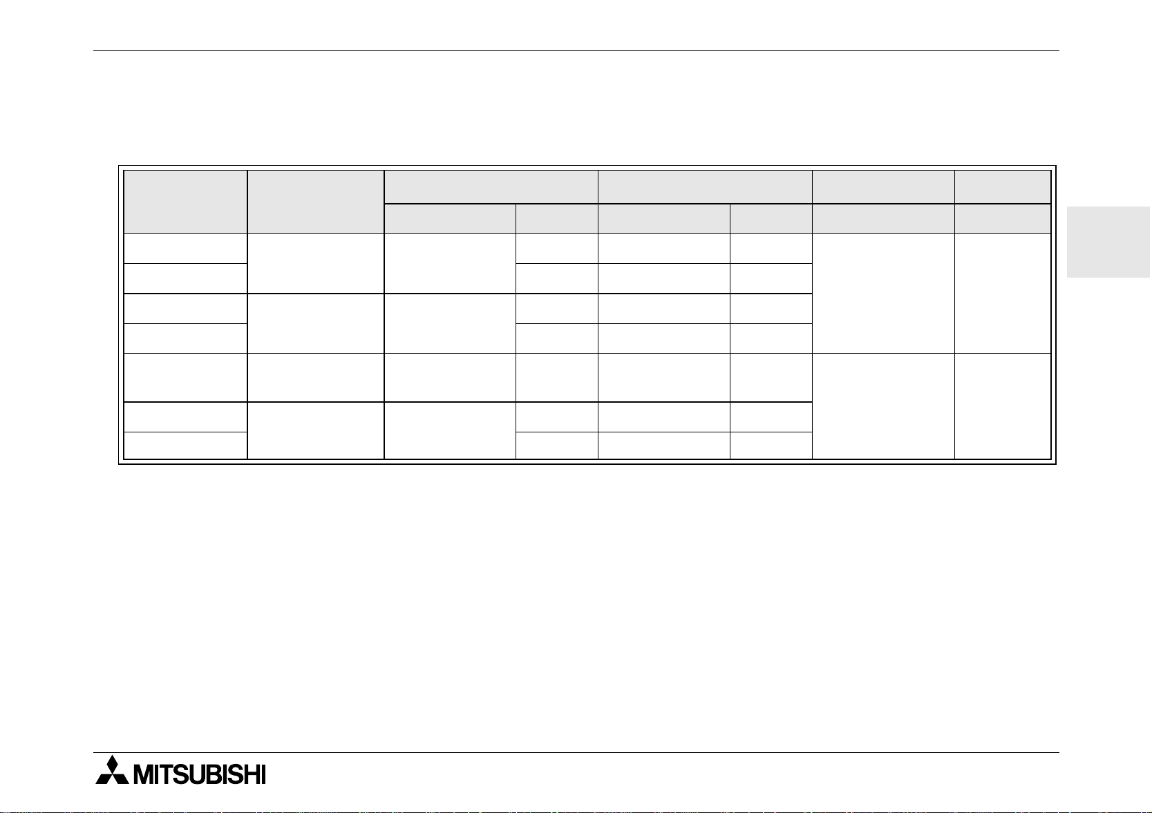
Table 2.1:Model Table
Input Output Dimensions Weight
Model Power Supply
Type Number Type Number mm (inches) kg (lbs)
AL-6MR-A
AL-10MR-A 6 RELAY 4
AL-10MR-D
AL-10MT-D 6 TRANSISTOR 4
AL-20MR-A
AL-20MR-D
AL-20MT-D 12 TRANSISTOR 8
* Without Special Connection Mo dules.
100 - 240V
AC~
24V DC
100 - 240V
AC~
24V DC
100 - 240V
AC~
24V DC
Sink/Source
100 - 240V
AC~
24V DC
Sink/Source
4RELAY 2
6RELAY 4
12 RELAY 8
12 RELAY 8
71.2 x 90 x 55
(2.80 x 3.54 x
2.17)
124.6 x 90 x 55
(4.91 x 3.54 x
2.17)
ENG
0.20
(0.44)
0.32
(0.70)*
3
Page 10
ENG
α
Simple Application Controller
2.2 Power Supply Specification
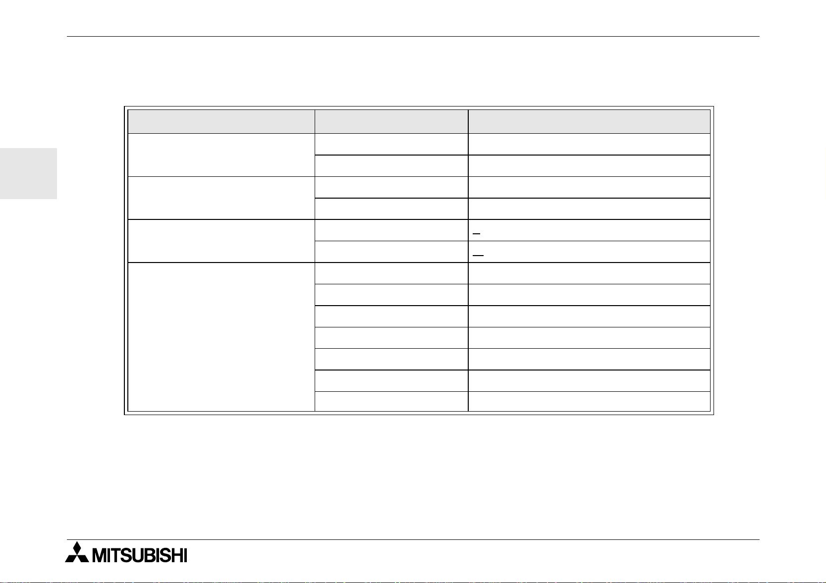
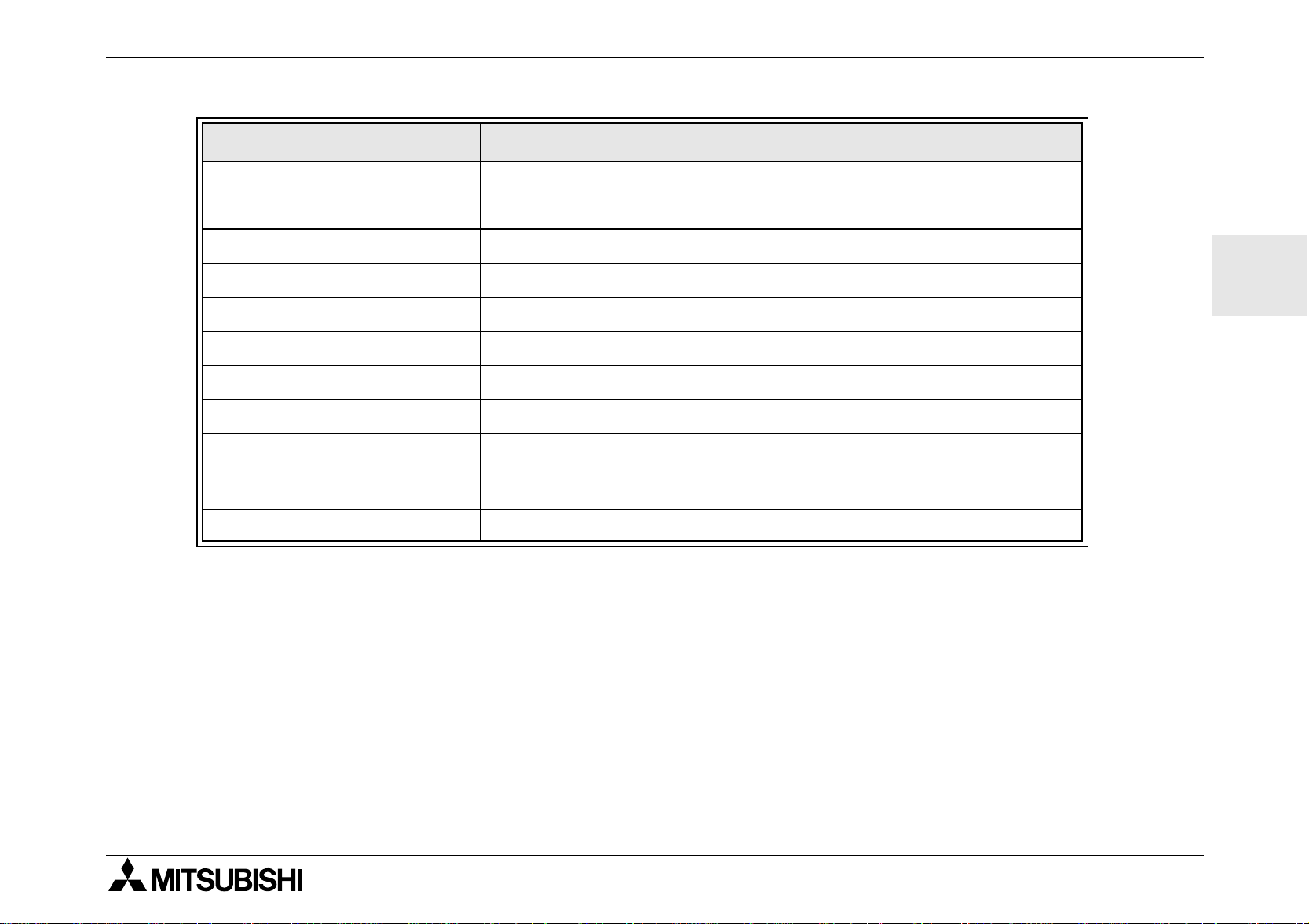
Table 2.2: Power Supply Specifications
Description Code Specification
Power Supply
Maximum Momentary Power
Failure
Hardware Specification 2
AL -***-A 100 - 240V AC~, +10% -15%, 50 - 60 Hz
AL-***-D 24V DC, +20% -15%
AL-***-A 10ms
AL-***-D 5ms
In-rush Current
Maximum Power Consumption
(without Special Connection
Modules)
240V AC~ (120V AC~) <
24 V DC <
AL-6MR-A, 264V AC~ 3.0 W
AL-10MR-A, 264V AC~ 4.0 W
AL-10MR-D, 28.8V DC 3.0 W
AL-10MT-D, 28.8V DC 2.0 W
AL-20MR-A, 264V AC~ 8.0 W
AL-20MR-D, 28.8V DC 7.0 W
AL-20MT-D, 28.8V DC 5.0 W
1.5 Amp (0.7 Amp)
7.0 Amp
4
Page 11
α
Simple Application Controller
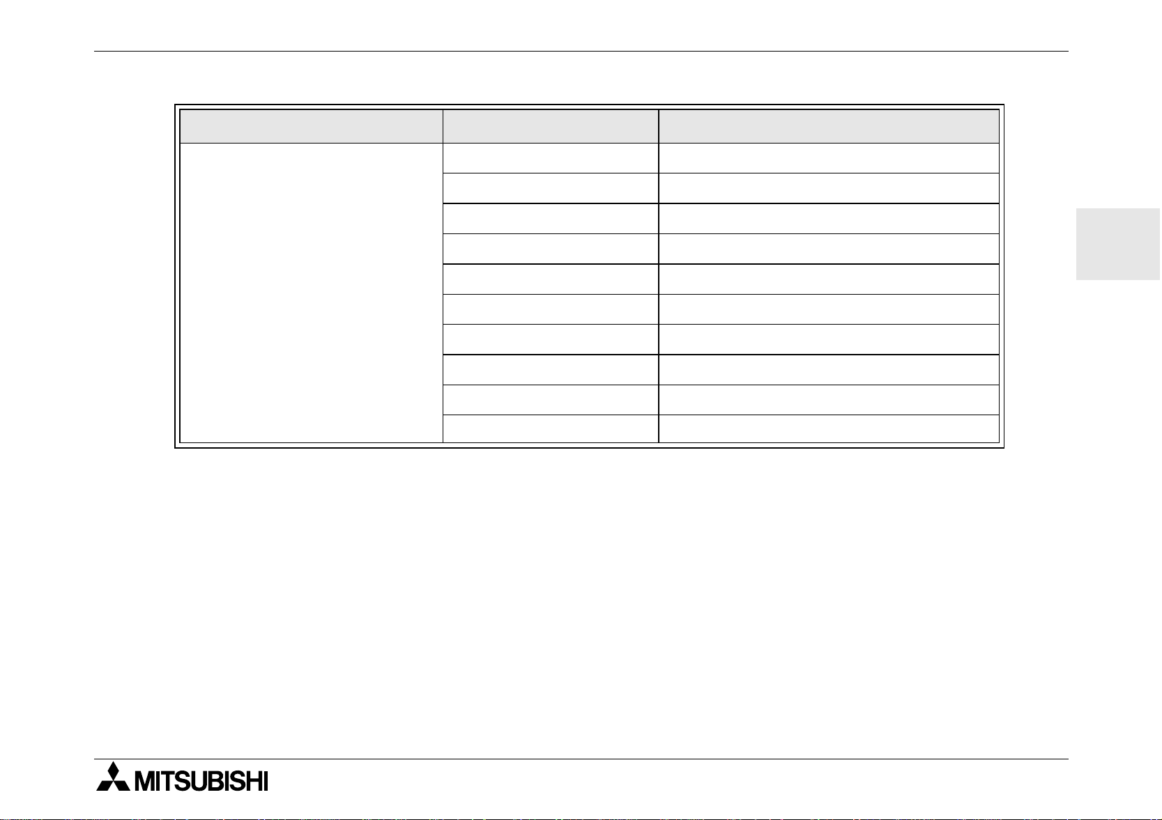
Table 2.2: Power Supply Specifications
Description Code Specification
Hardware Specification 2
AL-6MR-A, 240V AC~ I/O all On - 2.5 W, I/O all Off - 1.5 W
AL-6MR-A, 120V AC~ I/O all On - 2.0 W, I/O all Off - 1.2 W
AL-10MR-A, 240V AC~ I/O all On - 3.0 W, I/O all Off - 1.5 W
Typical Power Consumption
(without Special Connection
Modules)
AL-10MR-A, 120V AC~ I/O all On - 2.5 W, I/O all Off - 1.2 W
AL-10MR-D, 24V DC I/O all On - 2.0 W, I/O all Off - 0.3 W
AL-10MT-D, 24V DC I/O all On - 2.0 W, I/O all Off - 0.3 W
AL-20MR-A, 240V AC~ I/O all On - 5.0 W, I/O all Off - 1.5 W
AL-20MR-A, 120V AC~ I/O all On - 4.0 W, I/O all Off - 1.2 W
AL-20MR-D, 24V DC I/O all On - 5.0 W, I/O all Off - 0.3 W
AL-20MT-D, 24V DC I/O all On - 5.0 W, I/O all Off - 0.3 W
ENG
5
Page 12
α
Simple Application Controller
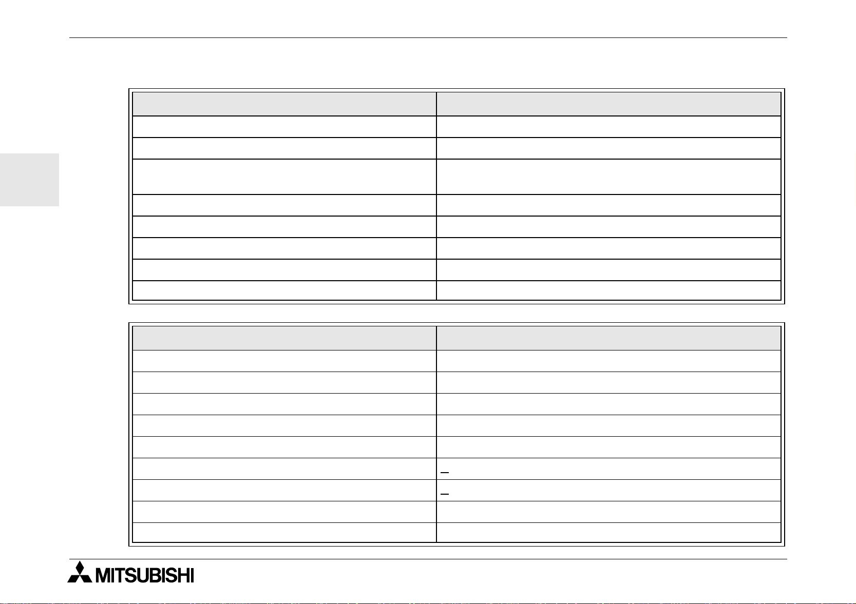
2.3 Input Specification
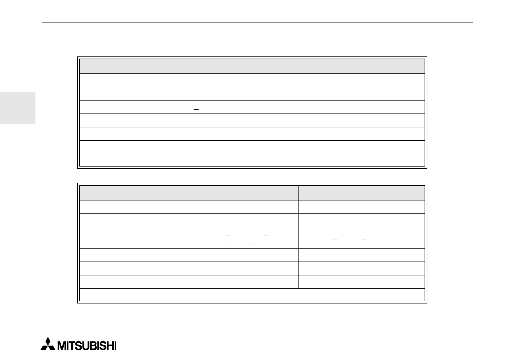
Table 2.3: AC Input Specifications
Description AC Inp ut Specific ation
Input Voltage 100 - 240V AC~, +10% -15%, 50 - 60 Hz
Input Current 0.24mA / 240V AC~, see Note 1
Hardware Specification 2
ENG
Input Impedance >
OFF to ON/ ON to OFF 80V/40V
Response Time ~ 50ms
Isolation Circuit None
Operation Indication Liquid Crystal Display
Table 2.4: DC Input Specifications
Description Sink (“-” Common) Source (“+ ” Common)
Input Voltage 24V DC +20% -15% 24V DC +20% -15%
Input Current 5.0 mA / 24V DC 5.0 mA / 24V DC
OFF to ON/ ON to OFF
Response Time (I01 - I08) 10 - 20 ms 10 - 20 ms
Response Time (I09 - I12) 20 - 40 ms 20 - 40 ms
Isolation Circuit None None
800 kOhms
Current: >
Voltage: <
4.3mA / < 1.1 mA
4V / > 18V
Vo ltage: > 18V / < 4V
Operation Indication Liquid Crystal Display
Note 1 - Current leakage from the sensors connected to the inputs might provide enough current to turn the
controller On. Do not use two wire sensors.
6
Page 13
α
Simple Application Controller
Table 2.5: Analog Input Specifications
Description Analog Input Specification
AL-10M*-D 6 Channels: I01 - I06
AL-20M*-D 8 Channels: I01 - I08
Analog Input Range 0 - 250
Hardware Specification 2
Resolution 10000/250 mv
Conversion Speed 10 ms
Input Voltage 0 - 10V DC
Input Impedance 150 kOhm or higher
Overall Accuracy +/- 5% (0.5V DC)
Offset Value = 0 at 0V DC
Offset/Gain
Temperatur e Drift +/- 3 LSB
Gain Value: 0 - 10V = 0 - 250
These default values can be changed in the Offset FB
ENG
7
Page 14
α
Simple Application Controller
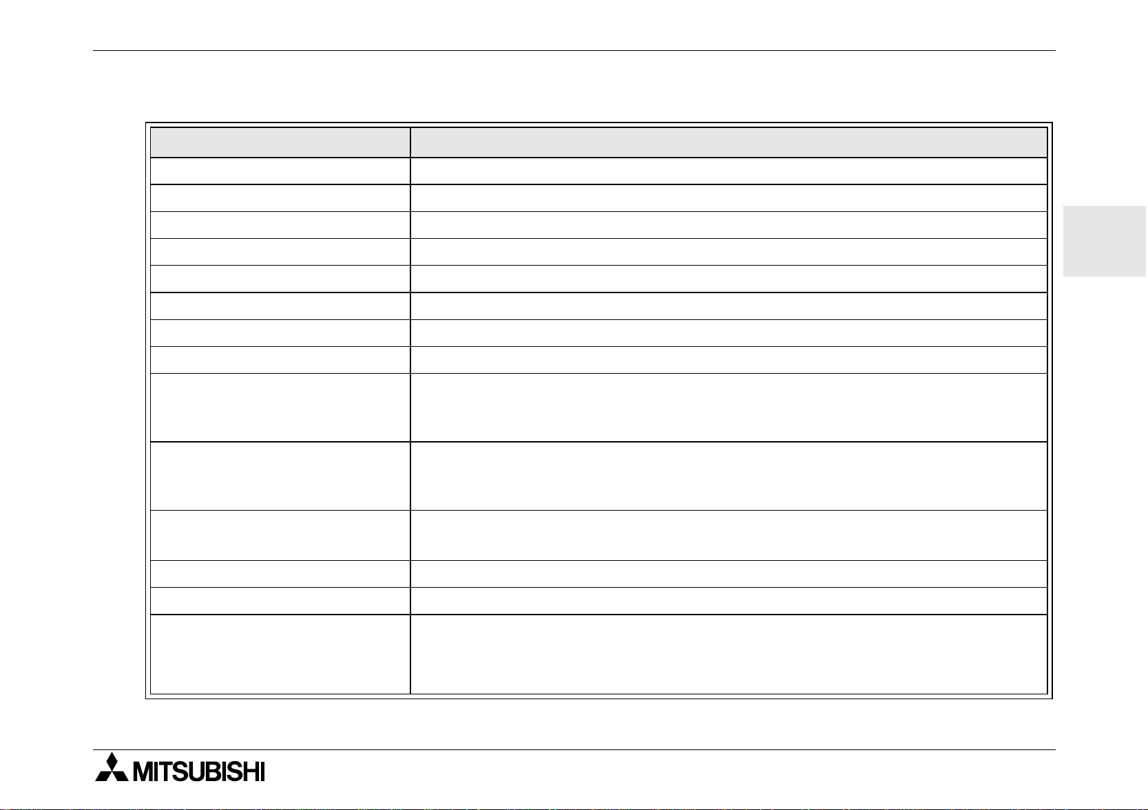
2.4 Output Specification
Table 2.6:Relay Output Specifications
Description Relay Specification
Switched Voltage 250V AC~ or less, 30V DC or less
Max. Resistive Load (AL-6M ** or AL-10M**) 8A / common (10A/common for 110V AC~ outputs)
Hardware Specification 2
ENG
Contact Life Cycle / Re sistance Load
Minimum Load 50mW (10mA at 5V DC)
Max. Inductive Load 245 VA (1/3 hp)/ 125 VAC~, 367 VA (1/2 h p) / 250 VAC~
Response Time 10ms or less
Operation Indication Liquid Crystal Disp lay
Isolation Circuit By Relay
Table 2.7: Transistor Output Specifications (Source Type only)
Description Transistor Specification
Switched Voltage 5 - 24V DC (+20%, -5%)
Max. Resistive Load 1A / point (8 - 24V DC), 0.1A / point (5 - 8V DC)
Minimum Load 1.0mA
Max. Inductive Load 1A / 24V DC (24 W)
Max. Lamp Load 0.125 A / 24V DC (3.0 W)
100,000 Cycles at 8 Amps / 240V AC~ or 24V DC
30,000 Cycles at 10 Amps / 110V AC~
Response Time On/Off, Off/On (approx) <
Open Circuit Current Leakage <
Operation Indication Liquid Crystal Disp lay
Isolation Circuit None
1 ms
0.1mA / 24V DC
8
Page 15
α
Simple Application Controller
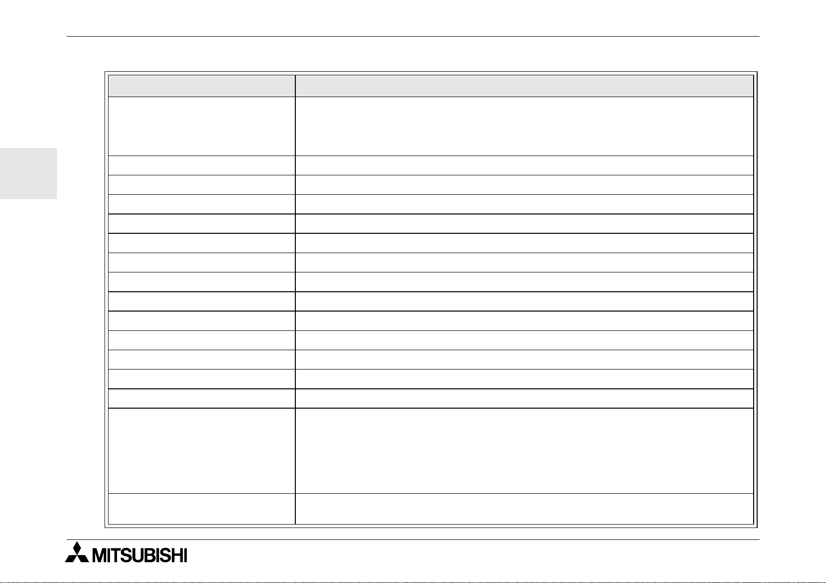
2.5 General Specification
Table 2.8:Environmental and Electrical Specifications
Description Specification
Progra mming Method Function Bloc k
Program Capacity 64 Function Blocks or 1500 bytes
Program Storage Built in EEPROM (no battery backup required) or opt ion al EEPROM cassette
Device Backup 20 Days at 25°C (by capacitor)
RTC Backup 20 Days at 25°C (by capacitor)
RTC Accuracy 5 seconds / day
Operating Temperature 0 - 55 °C
Storage Temperature (-30) - 70 °C
Hardware Specification 2
ENG
Vibration Resistance - D irect
Mounting
Vibration Resi stan ce - DIN Rail
mounting
Shock Resistance
Noise Immunity 1000Vpp, 1 microsecond, 30 - 100 Hz, tested by noise simulator
Humidity 35 - 85% Relative Humidity, no condensation
Dielectric withstand voltage
Conforms to IEC 68-2-6; 10-57 Hz: 0.15 mm Constant Amplitude
57-150 Hz: 19.6 m/s
Sweep Count for X,Y,Z: 10 times (80 minutes in each direction)
Conforms to IEC 68-2-6; 10-57 Hz: 0.075 mm Constant Amplitude
57-150 Hz: 9.8 m/s
Sweep Count for X,Y,Z: 10 times (80 minutes in each direction)
2
Conforms to IEC 68-2-27: 147m/s
3 times in each direction X,Y, and Z
3750V AC > 1 min per EN60730-1 between the following points:
Power/Input Terminals and Relay Output Terminals
Relay Output Terminal and Relay Output Terminal
All Terminals and the DIN 43880 Control box or equivalent
Acceleration, Action Time: 11 ms
2
Acceleration
2
Acceleration
9
Page 16
ENG
α
Simple Application Controller
Table 2.8:Environmental and Electrical Specifications
Description Specification
Insulation Resistance
Type of Action EN 60730-1, Section 6.4.3 - Type 1C (Relay Output)
Type of Action EN 60730-1, Section 6.4.3 - Type 1Y (Transistor Output)
Software Class EN 60730-1, Section H6.18 - Class A
Construction of Control EN 60730-1, Section 6.15 - Incorporated Control
Whether the Control is electric EN 60730-1, Section H2.5.7 - Electric Control
Hardware Specification 2
7 Mohm at 500V DC per EN60730-1 between the following points:
Power/Input Terminals and Relay Output Terminals
Relay Output Terminal and Relay Output Terminal
All Terminals and the DIN 43880 Control box or equivalent
Safety Class
Pollution Control For use in normal pollution situations
Grounding None
Electrical Isolation Reinforced primary/secondary insulation
Operation Ambience To be free of corrosive gases. Dust should be minimal.
Protection IP 20
Certifications CE, UL/cUL
Attestation of Conformity TÜV (AL-10MT-D, AL-10MR-D)
Complies with
Liquid Crystal Display
II
UL 508
EN60730-1
EN61010-1
EN50081-1
EN50082-1
EN61000-6-2
Will display 4 lines of ten characters per line, Program Run On/Off mode,
Pas s w ord P rotect ion, Imag e Table, and Functio n Bloc ks during pr ogr ammi ng.
10
Page 17
α
Simple Application Controller
3. Installation
Installation 3
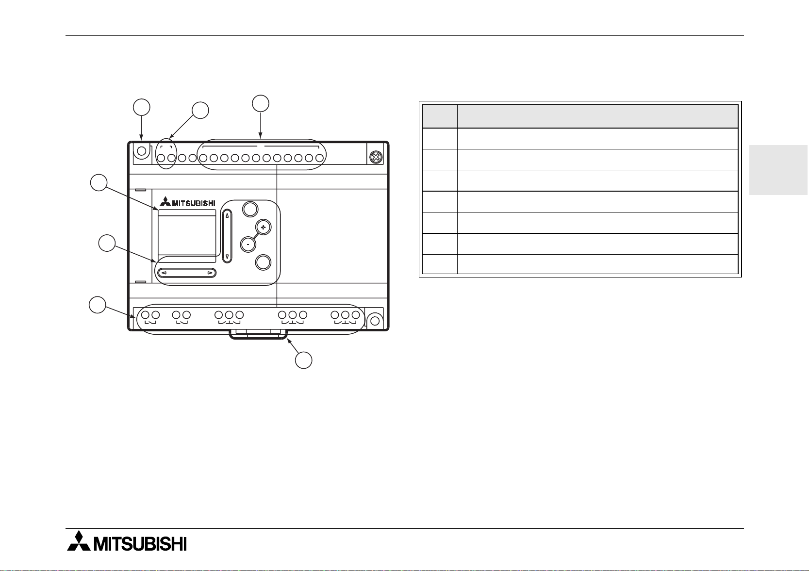
Tab le 3.1: Front Panel Layout
7
5
6
2
LN
POWER
AC 100-240V
OUT
1
3
~
1 2 3 4 5 6 7 8 9 10 11 12
4
Ref. Item Description
IN
1 DIN-RAIL Mounting clips
2 Mounting ho le, D ia. 4.2 mm
AC INPUT
ESC
3Power Terminals
4 Input Terminals
ENG
5 Liquid Crystal Display
6 Operation keys
OK
AL-20MR-A
RELAY OUTPUT
7 Output Terminals
3.1 DIN RAIL Mounting
Units can be snap mou nted t o 35mm DIN ra il (DIN
OUT
OUT
OUT
2
3
OUT
4
5
OUT
6
OUT
OUT
8
7
EN 50022). To release pull the spring loaded clips
away from the rail and sli de the unit off and up.
1
3.2 Termination at Screw Terminals
Cables terminati ng at a screw ter minal should be
fitted with insulated crimp terminals.
11
Page 18
α
Simple Application Controller
3.3 Installation Mounting Notes
Installation 3
ENG
The α Series’ safe design means the
user can install it almost anywhere but
the f ollowing points sho uld be taken into
consideration.
Do not install i n are as wit h: excessive or
conductive dust, corrosive or flammable
gas, moisture or rain , excessive heat,
regular impact shocks or excessive
vibration. Do not place in water or let
water leak onto the controller.
Do not allow debris to fall inside the unit
during installation.
Keep as far as possible from
high-voltage cables and power equipment.
The
Series Controller must be
α
installed in ca bin ets which are designed
for the assembly of devices complyin g
to DIN 43880 or in a control box.
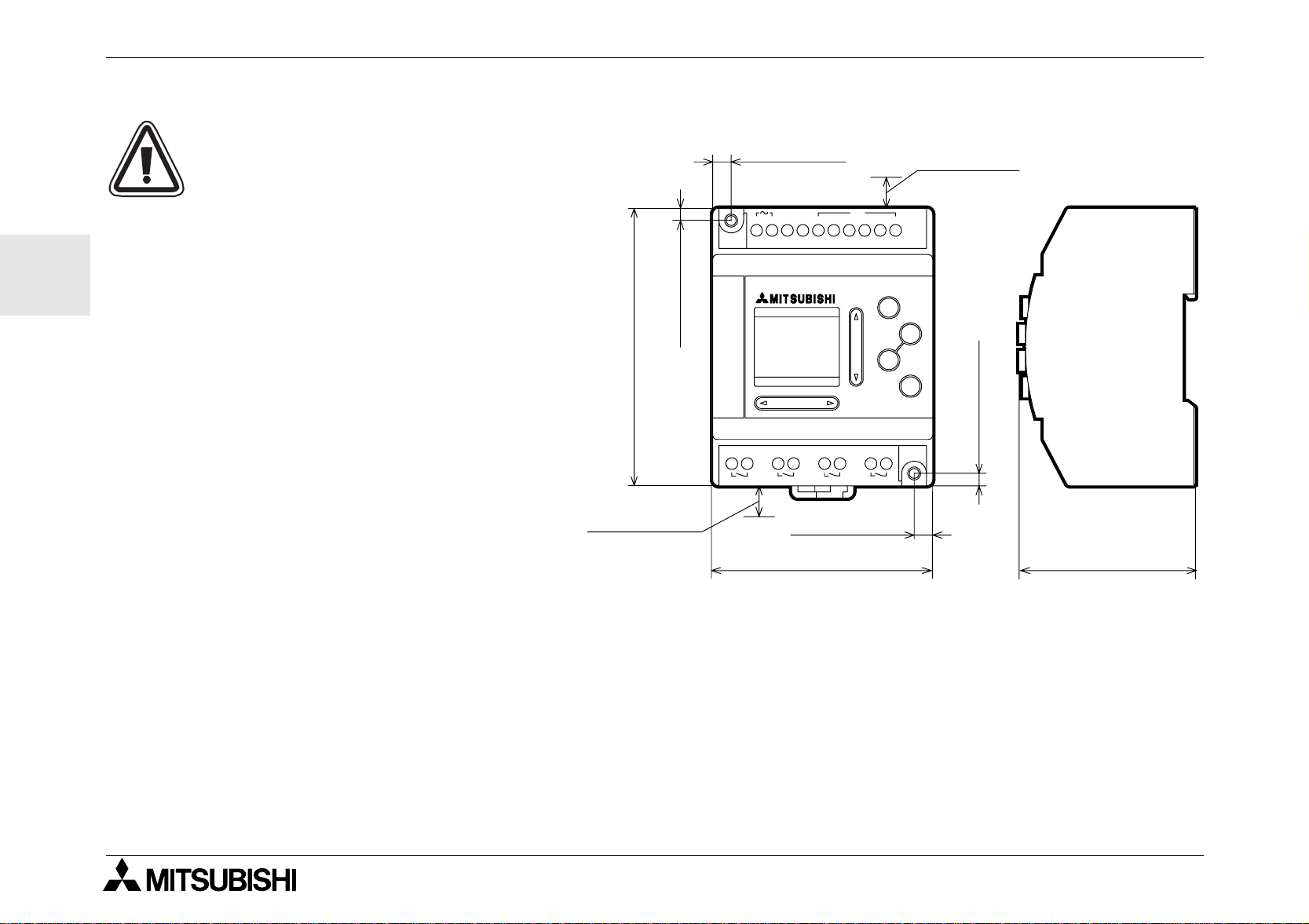
4.0(0.16")
90.0(3.54")
10(0.39")*
6.0(0.24")
POWER
AC 100/240V
RELAY OUTPUT
OUT3 OUT4OUT2OUT1
6.0(0.24")
71.2(2.80")
IN
34215L6N
AC INPUT
10(0.39")*
ESC
+
-
OK
4.0(0.16")
55.0(2.17")
Use size M4 screws when mounting by screw holes.
The connectors must be covered to prevent injury from contact with “live” wires.
* Leave a minimum of 10mm of space for ventilation between the top and bottom edges of the
troller and the enclosure walls.
Series Con-
α
12
Page 19
α
Simple Application Controller
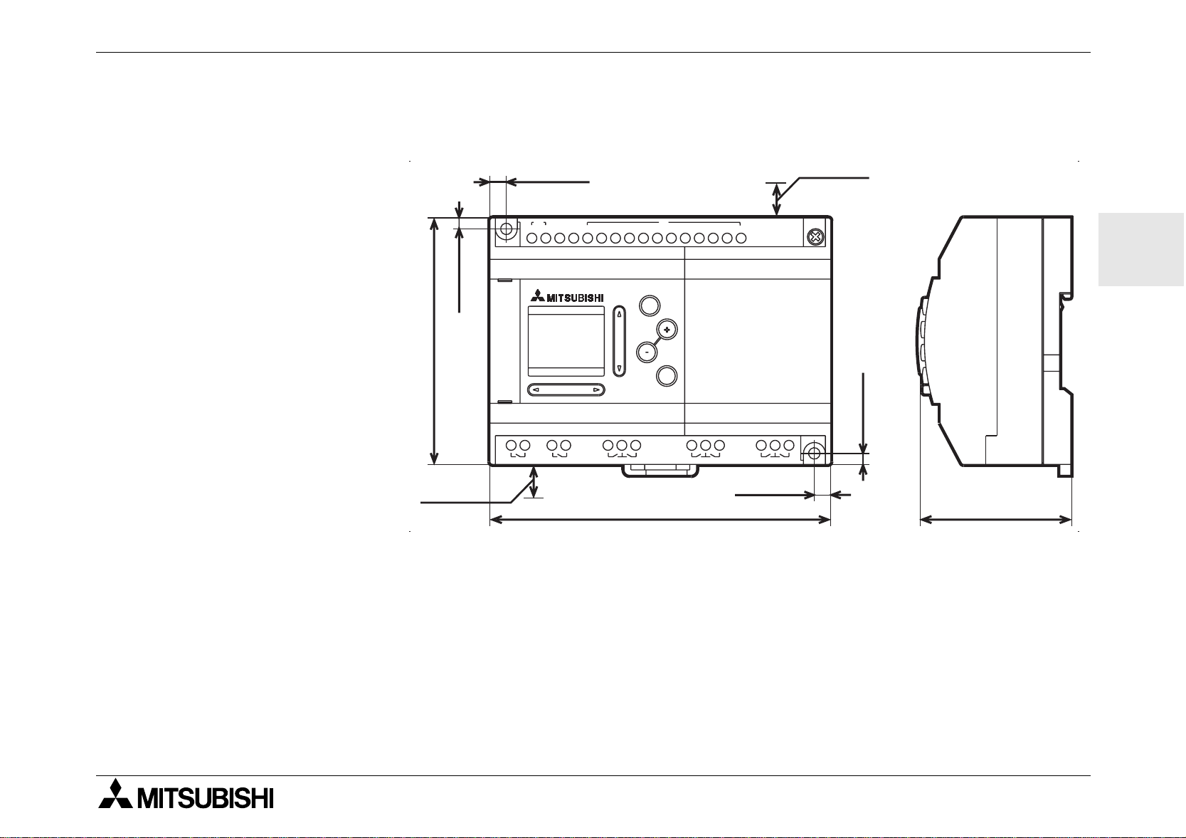
Do not disassemble the α Series controller. Ref er to the Memory Cassette Manual when ch anging th e Memory Cassette.
Installation 3
4.0(0.16")
90.0(3.54")
10(0.39")*
6.0(0.24")
~
LN
POWER
AC 100-240V
OUT
OUT
1
1 2 3 4 5 6 7 8 9 10 11 12
OUT
2
3
IN
AC INPUT
ESC
OK
AL-20MR-A
RELAY OUTPUT
OUT
4
124.6(4.91")
10(0.39")*
ENG
4.0(0.16")
OUT
5
OUT
6
6.0(0.24")
OUT
8
OUT
7
55.0(2.17")
13
Page 20

ENG
α
Simple Application Controller
Installation 3
14
Page 21
α
7mm(0.276") ± 0.5mm(0.02")
26 -12 AWG
Simple Application Controller
4. Wiring
4.1 Installation Wiring Notes
The wiring of α Series has been designed to be safe and easy. A technician or engineer trained in the local
Wiring 4
and national electrical standards should perform all tasks associated with the electrical wiring of the
controllers. Turn off the Power before performing any wiring operations.
• Input and output cables should not be run through the same multicore cable or share the same wire.
• Do not lay input/output cables near high voltage power cables.
Allow for voltage drop and noise interference with input/output lines used over an extended distance. Please
use wire that is properly sized for the current load.
4.2 Wire Size and Specifications
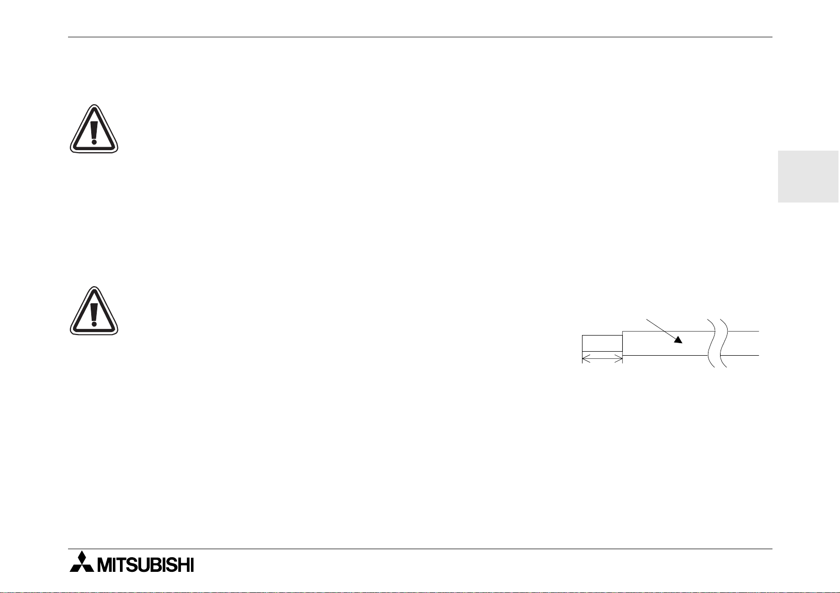
Wire the Inputs and Outpu ts using 26 - 12 AWG wire (0.13 mm2 - 3.31
2
mm
). Strip the wire to a length of 7 +- 0.5 mm (0.250 - 0.300 inches).
Please unscrew the terminal to its widest position before inserting a wire.
Insert the wire completely into the terminal to ensure that a proper connection can be made. Insert the wire into the terminal and tighten enough
to keep the wire from pulling free. To avoid damaging the wire, do not
exceed a maximum torque of 0.5 N⋅m. Please do not use tin, solder, or
any other substance on the stripped wire that might cause the wire strand
to break.
Series
α
ENG
The terminals will accept a 3mm flathead screwdriver.
15
Page 22
ENG
α
Simple Application Controller
4.3 Power Supply
When wiring AC supplies the “Live” cable should be connected to the “L” ter minal and the “Neutral” cable
should be connected to the “N” terminal. Do NOT connect the “Live” wire to the “N” terminal, the user might
receive a dangerous shock on powerup.
When wiring DC supplies the “positive” cable should be connected to the "+" terminal and the negative cable
should be connected to the “-” terminal. On no account should the power supply terminals be connected to
any other terminal on the unit. DC Power Supply units should be capable of providing 4 Amperes of current
to the controller.
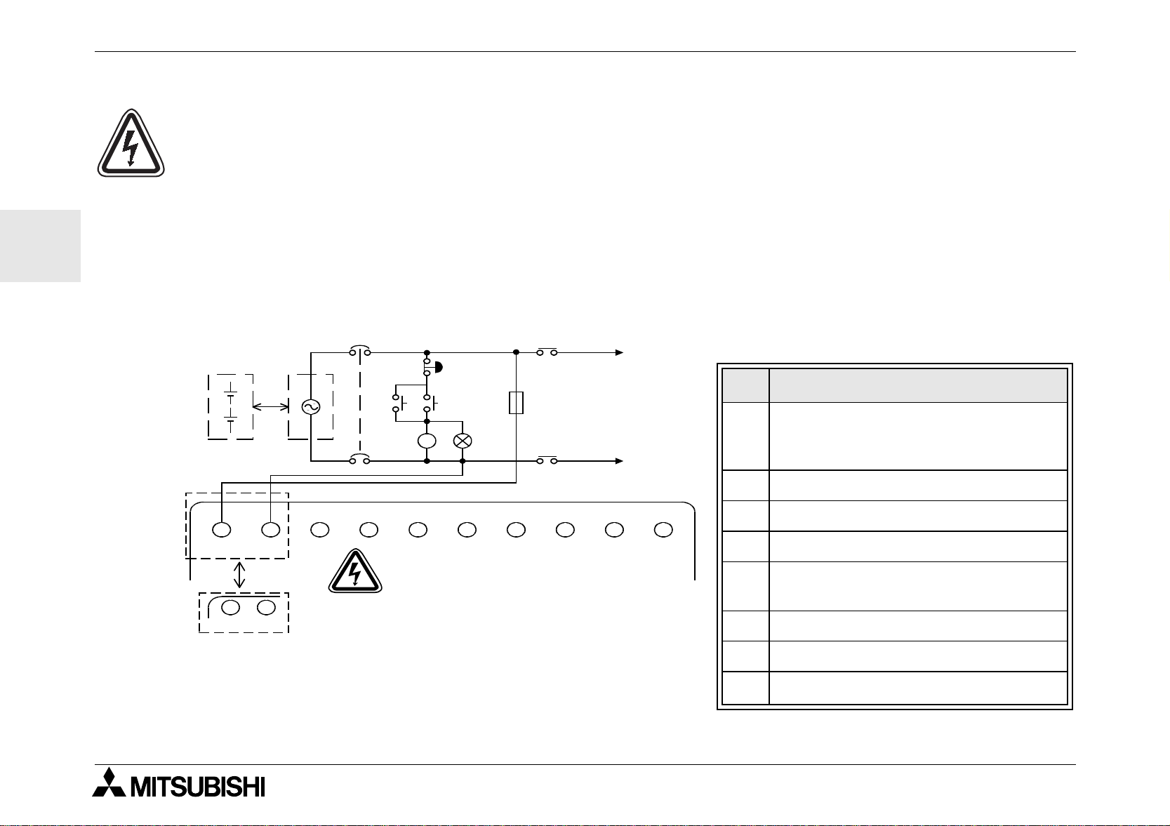
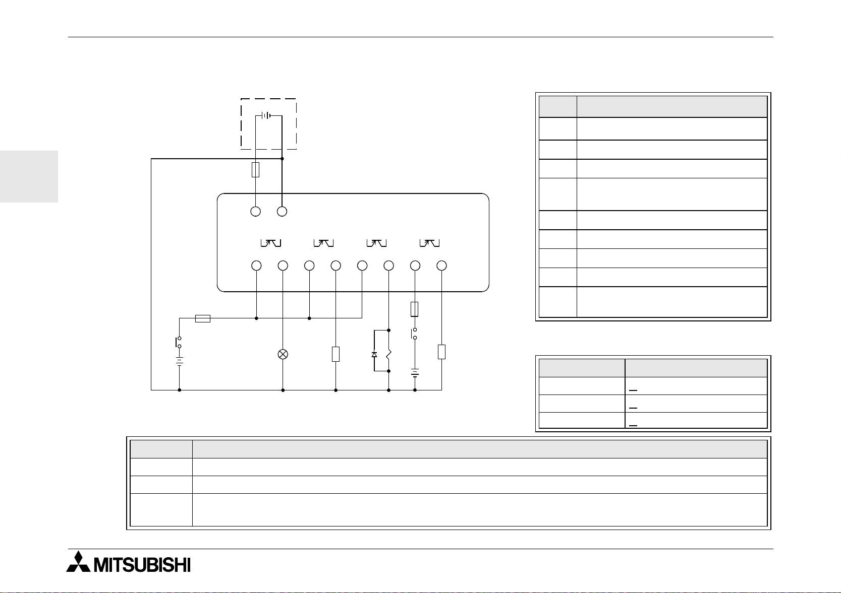
4.4 Recommended Power Input Wiring Diagram
%
MC
&
(
MC
+
−
!"
L
MC
N
MC
#
Start
$
Wiring 4
Table 4.1:Recommended Power Wiring
Ref. Item Description
Power Supply: AC~:100-240V
1
50-60Hz
DC: 24V
2 Circuit Isolation Device
LN
+−
'
"L" and "N" terminals are not
reversible.
3 Emergency Stop
4 Power On Pilot Indicator
5
Circuit protection device - limit to
1.0 Amps
6 Power Supply for AC loads
7 Magnetic Switch Contact
8
Base Unit
α
16
Page 23
α
Simple Application Controller
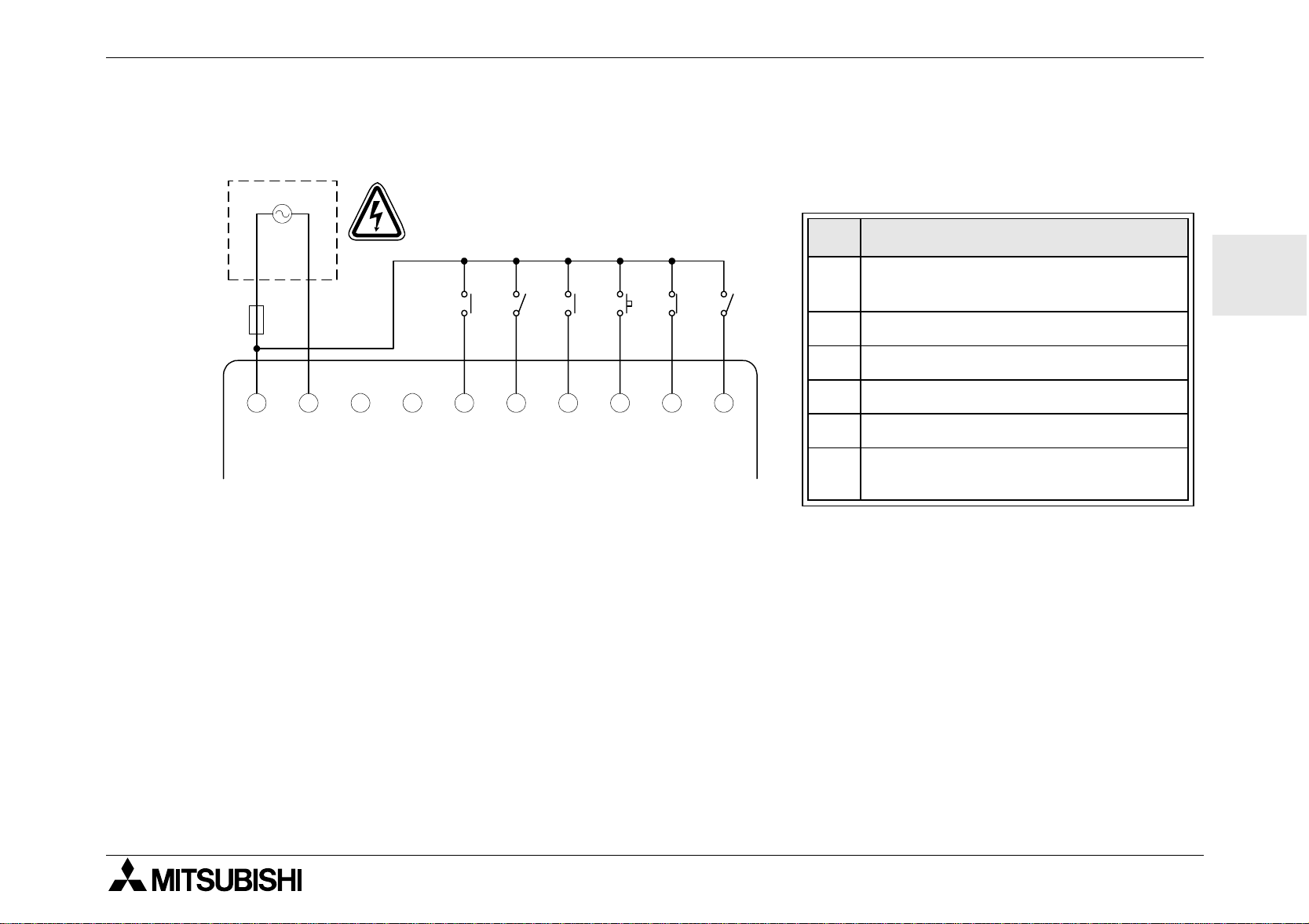
4.5 AC Input Wiring
4.5.1 AC Input Wiring Diagram
Wiring 4
!
LN
"L" and "N" terminals are not
reversible.
&
LN 123
#
"
456
INPUTS
$
%
Table 4.2: AC Input Typical Wiring
Ref. Item Description
1
2 AC Power Terminals
3 Unused Terminals
4 Input Terminals
5 Digital Input Switches
6
AC Po wer Sup ply, 100 - 240V AC~
50 - 60 Hz
Circuit Protection Device - Limit to
1.0 Amps
ENG
17
Page 24
α
Simple Application Controller
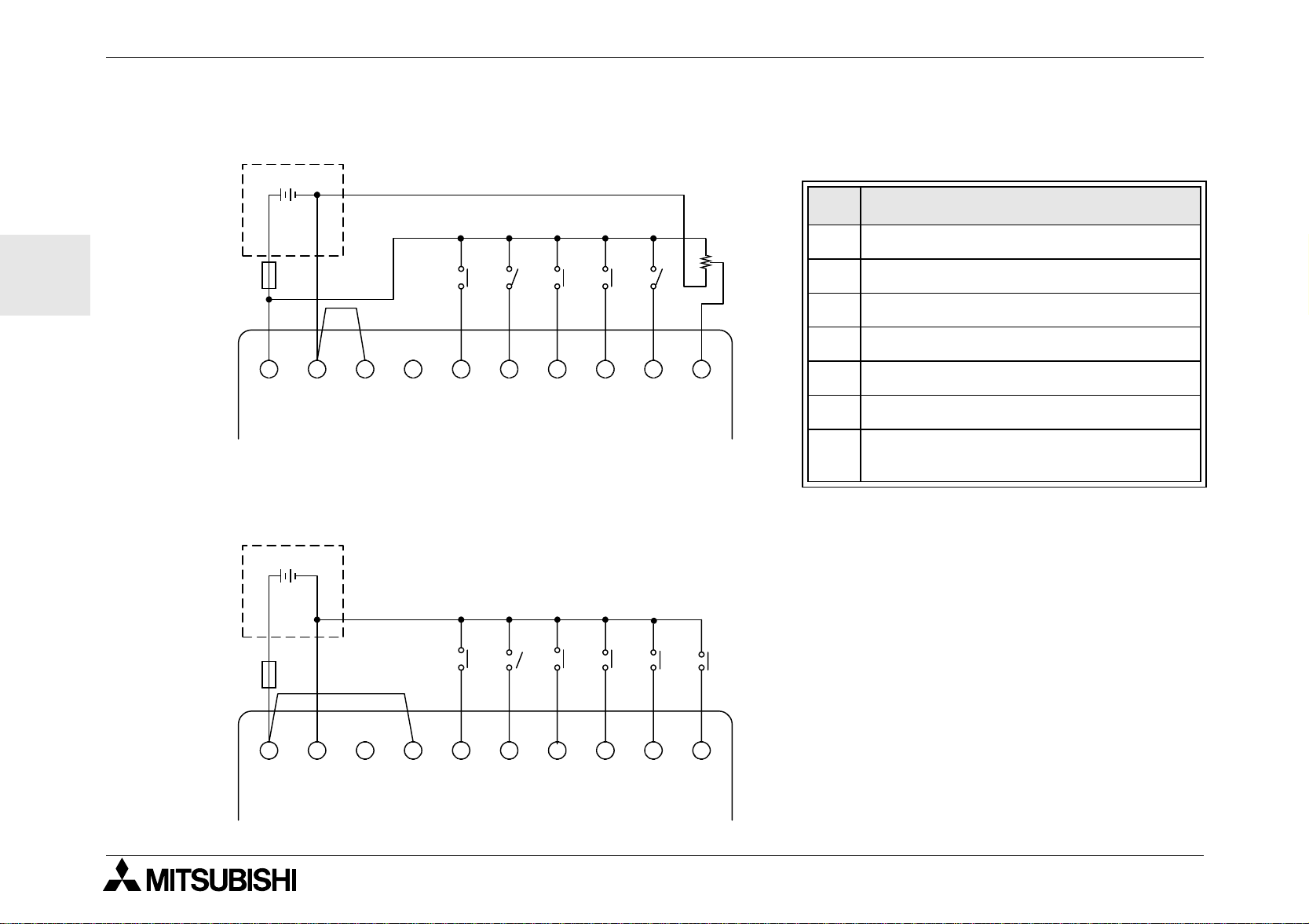
4.6 Wiring Diagrams for the Sink/Source Terminals
4.6.1 Source (“+” Common) Input Wiring Diagram
!
+−
Wiring 4
Table 4.3: Sink/Source Input Wiring
Ref. Item Description
ENG
(
+−
"
(A) (B)
#
123
INPUTS
456
$
4.6.2 Sink ("-" Common) Input Wiring Diagram
!
+−
(
%
%
&
1 DC Service Supply, 24V DC
2 DC Power Terminals
3 Sink/Source Input Wiring Terminals
4 Input Terminals
5 Sensor Input Switches
6 Analog Input
7
Circuit Protection Device - Limit to
1.0 Amps
+−
(A) (B) 1 2 3
"#
INPUTS
$
456
18
Page 25
α
Simple Application Controller
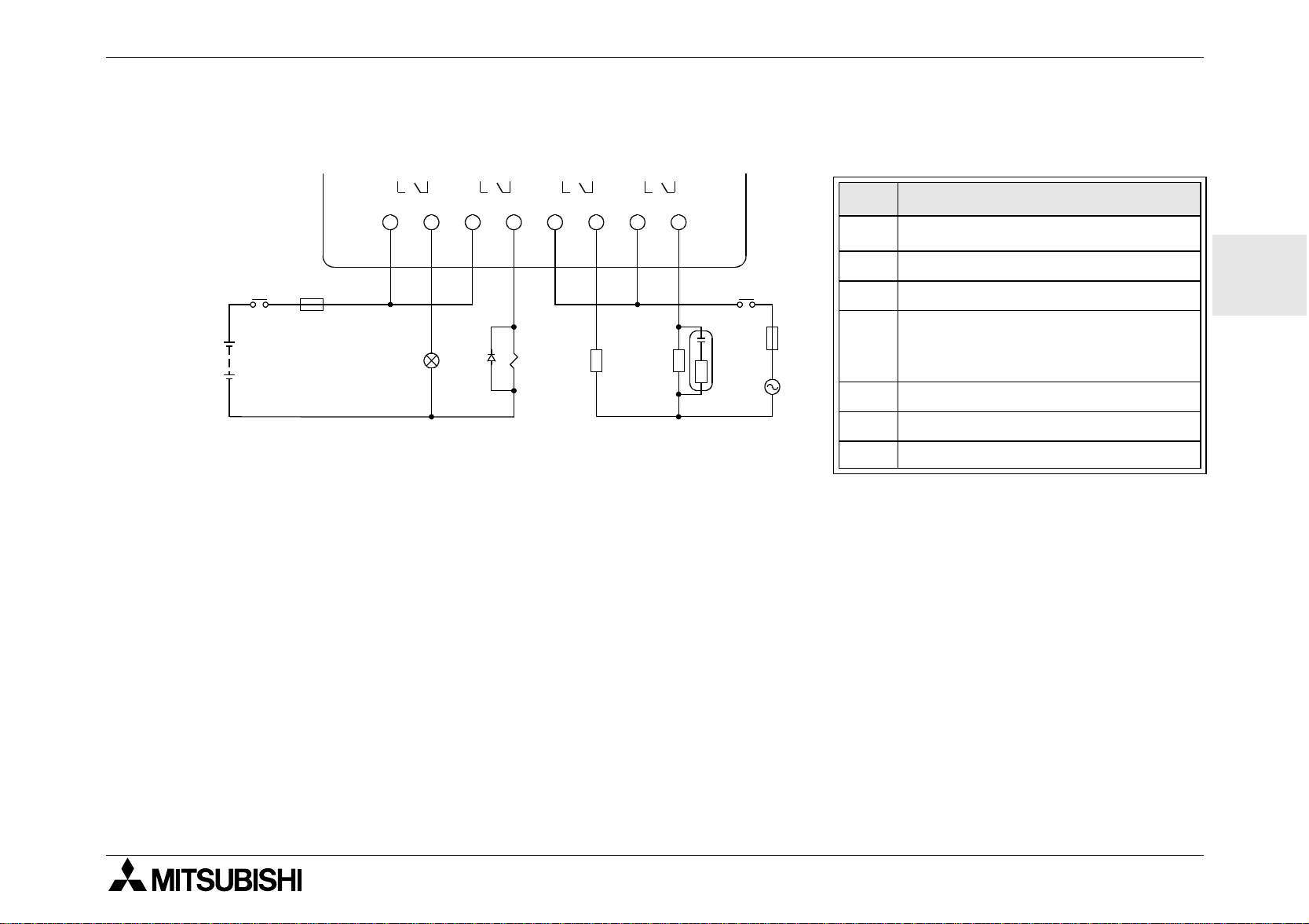
4.7 Output Relay and Transistor Wiring
4.7.1 Relay Output Wiring Diagram (AC and/or DC)
"!
OUT1
OUT2 OUT3 OUT4
Wiring 4
Table 4.4: Relay Output Wiring
Ref. Item Description
&
1
2 Mutually exclusive outputs
%
+
$
##
%
$
(
3 Output Devices
4
5 Emergency Stop
6 DC Power Supply
7 AC Power Supply
Base Unit
α
Circuit Protection Device - Limit
to 10 Amps per every four output terminals used.
ENG
19
Page 26
α
Simple Application Controller
4.7.2 Transistor Output (Source or “+” Common Only) Wiring Diagram
Table 4.5: Transistor Output Wiring
Wiring 4
ENG
%
&
'
+−
Ref. Item Description
1
Base Unit
α
2 Output Terminals
)
(
+−
OUT1
!
"
OUT2 OUT3 OUT4
3 Output Devices
Circuit Protection D evice - See
4
Table 4.6 for Specifications
5 Emergency Stop
6 DC Power Supply for output
7Power Terminal
8 DC Power Supply, 24V DC
Circuit Protection Device
9
- Limit to 1.0 Amps
Table 4.6: Tran si stor Output Circuit
Protection Table
Circui t V oltage Circuit Protection (Fuse)
%
&
$
#
+
$
+
#
#
5 Vo lt < 0.3 Amps per Circuit
12 Volt <
24 Volt <
Volt Output Terminal Notes
2.0 Amps per Circuit
2.0 Amps per Circuit
5 Each circuit can contain from on e output ter m inal up to every output te rminal.
12-24 Each circuit can contain from one output terminal up to every output terminal.
Using any combination of 5 Volt, 12 Volt, and 24 Volt outputs can be accomplished on the same
5,12,24
Series Controller if separate circuits are used for each voltage level.
α
20
Page 27
α
LN 1234
OUT1
AL-10MR-A
OUT2
IN
56
OUT3
OUT4
+−
(B)
1234
OUT1
AL-10MT-D
OUT2
IN
56
OUT3 OUT4
(A)
Simple Application Controller
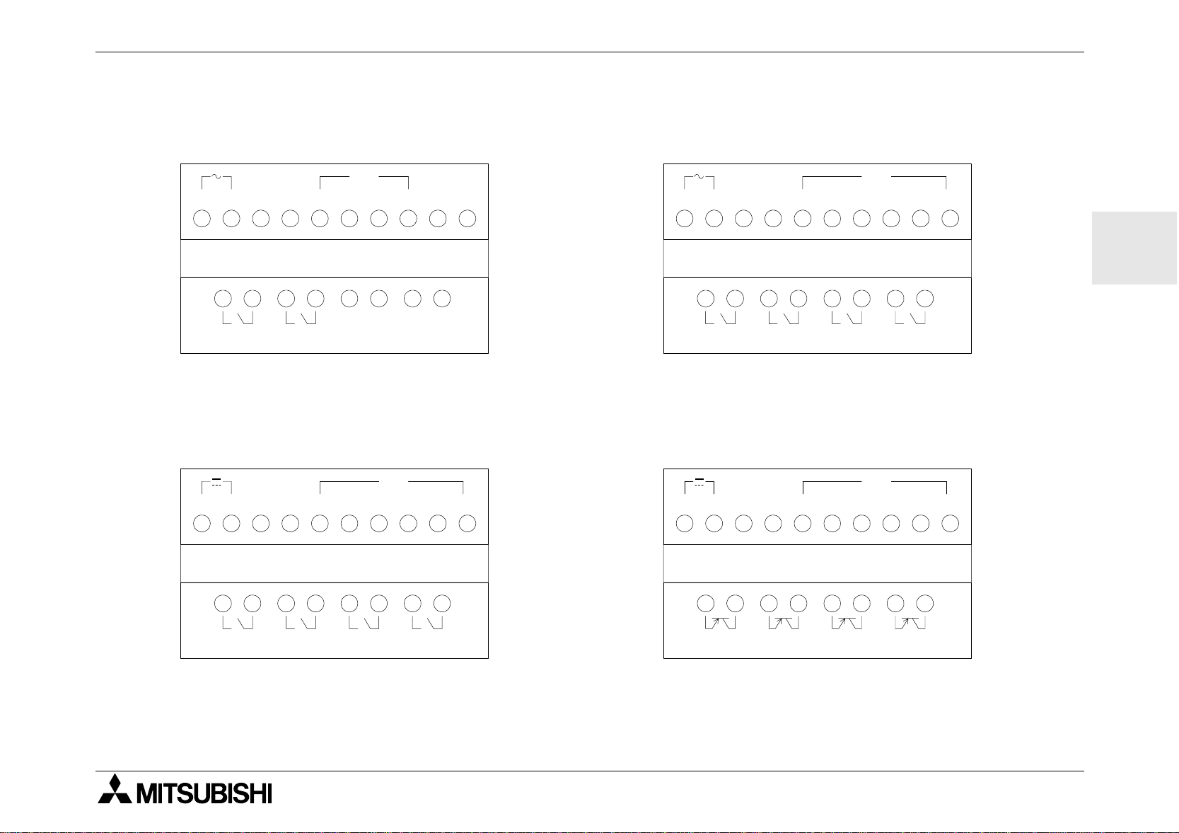
Series Terminal Layout 5
αααα
5.
αααα
Series Terminal Layout
AL-6MR-A, AC Input, Relay Output AL-10MR-A, AC Input, Relay Output
IN
LN 1234
AL-6MR-A
OUT1
OUT2
AL-10MR-D, DC Input, Relay Output AL-10MT-D, DC Input, Transistor Output
IN
+−
(A) (B)
1234
56
ENG
AL-10MR-D
OUT1
OUT2
OUT3
OUT4
21
Page 28
ENG
α
Simple Application Controller
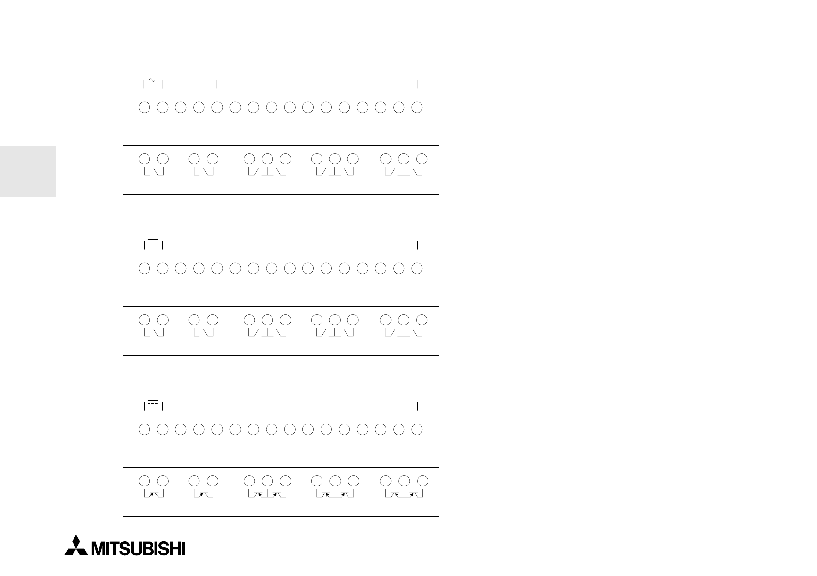
AL-20MR-A, AC Input, Relay Output
LN
AL-20MR-A
OUT1
OUT2 OUT3 OUT5 OUT7OUT4 OUT6 OUT8
AL-20MR-D, DC Input, Relay Output
-
+
AL-20MR-D
(A) (B)
IN
IN
Series Terminal Layout 5
αααα
121112345678910
121112345678910
OUT1
OUT2 OUT3 OUT5 OUT7OUT4 OUT6 OUT8
AL-20MT-D, DC Input, Transistor Output
IN
-
+
AL-20MT-D
OUT1 OUT2
(A) (B)
OUT3 OUT5 OUT7OUT4 OUT6 OUT8
121112345678910
22
Page 29
α
0 1
I n
0 1
A d d F B
O 0 1
C o n n e c t
Simple Application Controller
How to Use
Series Controllers - Getting Started 6
αααα
6. How to Use
Series controllers use Function Block Programming. In this style of programming, Function Blocks are con-
α
nected together to b uild a prog r am. Ther e are f iv e types o f b loc ks that can be pl aced in y our prog r am: Syst em
nputs, front panel Keys, System M bits, Function Block s, and System Outputs.
I
A screen showing the date, time, and image table (input and output status) will show when the controller is
turned On. Hit any key to proceed to the To p Menu. Enter the ProgEdit mode with the OK key to begin programming.
αααα
Series Controllers - Getting Started
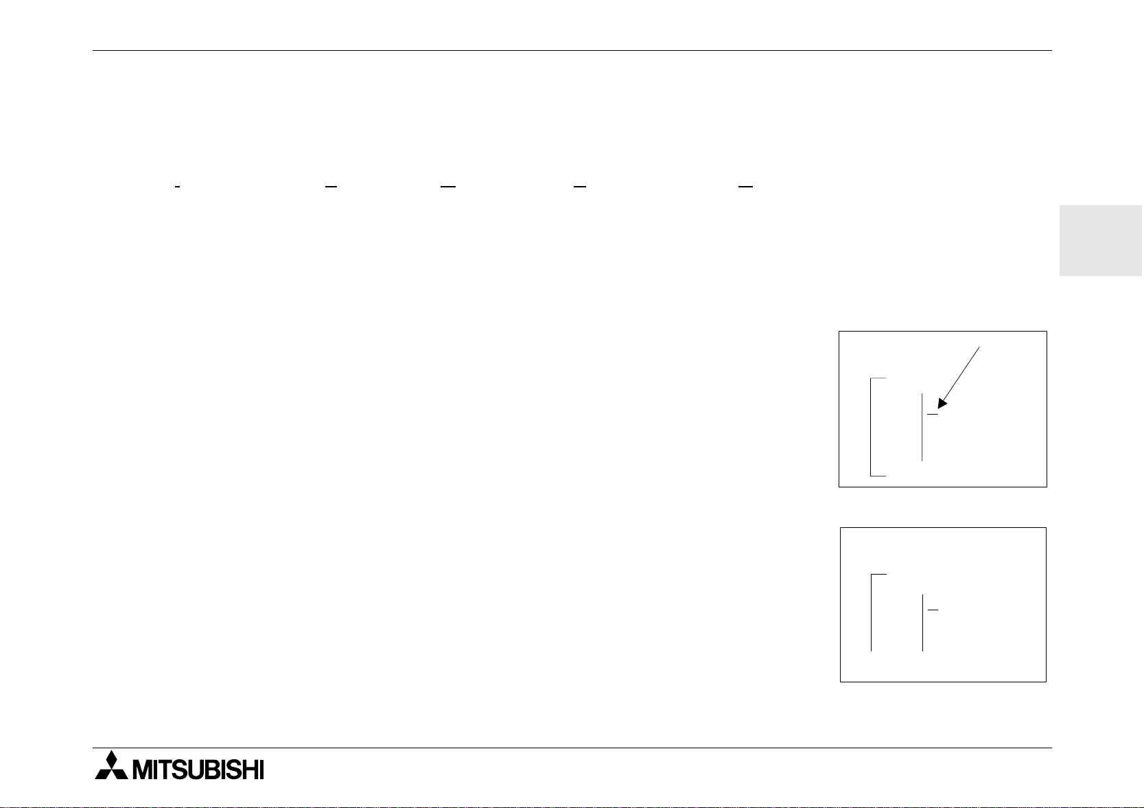
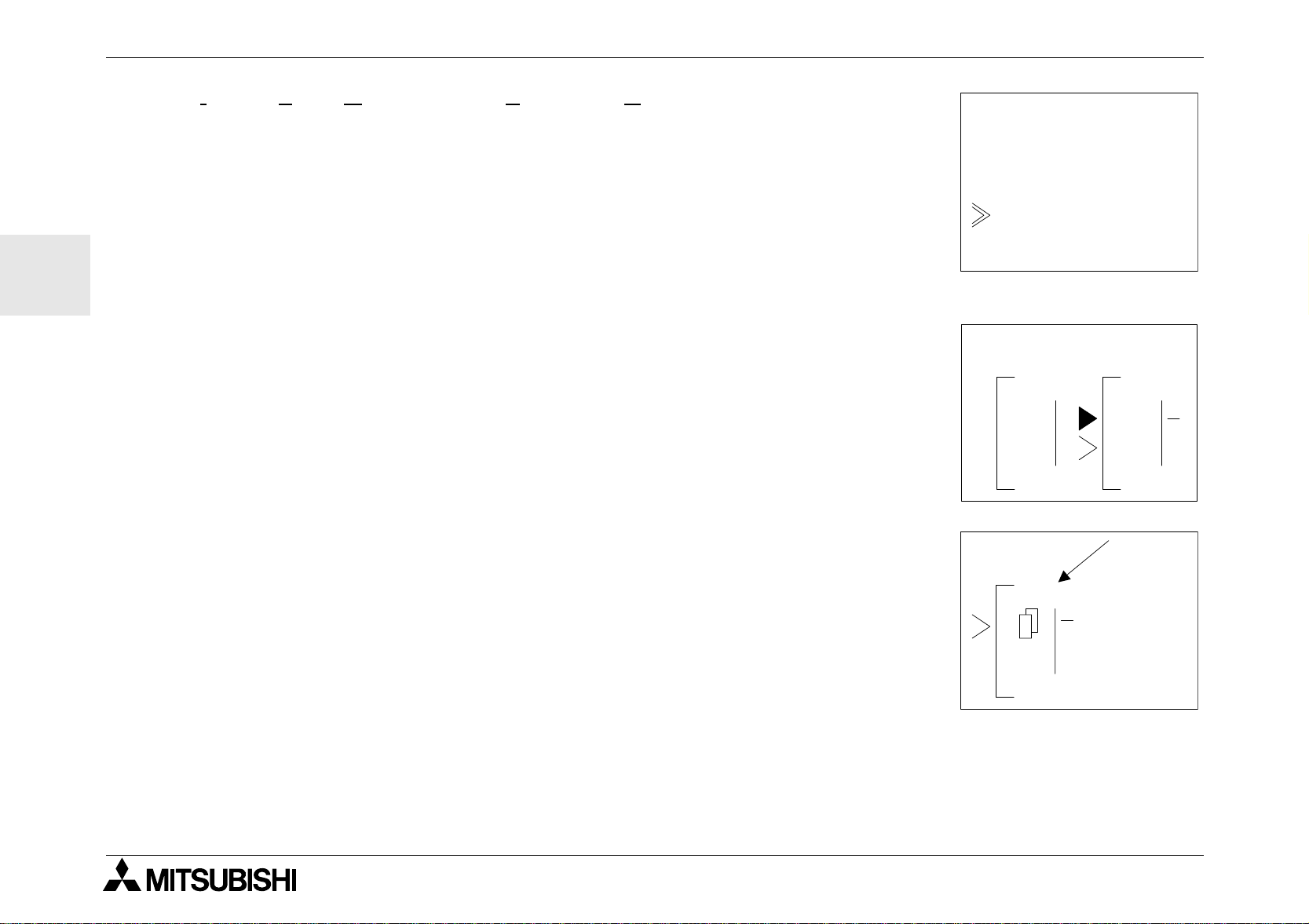
6.1 Connecting Two Blocks
Function Blocks (FB) are connected by joining an output pin to an unused input
pin. The arrow is pointing to the output pin. The out pu t pin is always shown on
the right side of the function blocks. Unused Input pins are shown as “>” while
used input pins show as a solid triangles. Press the right arrow button to move
the screen to the r ight until the output pin is flashing. U se the “+” key to connect or “add” a FB. The “-” key will disconnect two devices.
ENG
Press the “+” key. The FB options available for connection appear on the right
of the screen. Use the U p and Down arrows to move to the desired device to
add. The curren t cho ice will be blinking. A “Connect” prompt will app ear on the
top or bottom of the screen. Choose the desired connecting block with the OK
key
23
Page 30
ENG
Hourm eter
Pulse
F B S e l e c t
Tim e S W
AND
01 01
OUT
0 3
F L
α
Simple Application Controller
Inputs, Keys, M bits, Function Blocks, and Outputs will automatically show
whenever they can be connected. Function Blocks must be added durin g the
course of progr ammin g.
To add a new FB, select AddFB. The AddFB menu will show the list of twentytwo function blocks (see function block descriptions at the end of this chapter).
Choose the appropriate block with the OK key.
Choose an open (“>”) input pin and ent er OK. The “connect” p rompt should
disappear from the screen - the two function blocks are now connected!
Output pins can be connected to multiple input pins but input pins can have
only one connection.
How to Use
Series Controllers - Getting Started 6
αααα
6.2 Accessing Blocks
When the FB number is flashing, use the “+” and “-” keys to scroll through adjacently numbered blocks.
Ex. Input number 0 3 flashi ng on the d isplay. Pressing the “+” ke y will move the
screen to Input number 04. Inputs, Outputs, Keys, and Memory bits can be
accessed in this manner.
Function Blocks will perform the same operation but will scroll only through the
Function Blocks that have been added to the program.
24
Page 31

α
t = 0 . 0 s
O n T i m e
B 0 3 : F L
T = 0 . 0 s
E d i t M e n u
E x i t
P r o g S i z e
J u m p
N e w F B
M n e m o n i c
T o p M e n u
C l o c k S e t
R u n
P r o g E d i t
P r o g C l e a r
O t h e r s
. . .
L A N G U A G E
Simple Application Controller
6.3 Setting Function Block Parameters
Some Function Bloc ks ha ve parameters that ne ed to be set. Thes e parame ters
include Time (T), elapsed time (t), Set Repetitions (N), actual repetitions (n),
Set/Re set Priority a n d more.
Use the arrow keys to move to the FB. When the FB number is flashing, enter
OK twice to enter the FB Setup mode. Adjust the options to fit the program
requirements (refer to Key Operations Table 6.1). Enter all the necessary data
on each screen before using the OK button to accept.
Some FB have multipl e o pti on screens available. Use the ESC key to mo ve to a high er s c r ee n without saving
the contents to system memory. When finished entering data, use the ESC button to return to higher screen
levels until the main programming screen is shown again.
6.4 Exiting, Running, and Stopping the Program
Use the ESC button to ente r the Edit Menu (the ES C button might have to be
pressed more than once) and use the Exit option to leave ProgEdit.
How to Use
Series Controllers - Getting Started 6
αααα
ENG
Use the Run option to begin th e prog r am. Confi rm with OK. When the prog r am
is running the front screen is shown with the time, date, and image table.
Press any key to enter the Top Menu where the Stop option i s locate d. Enter
this option to Stop the program and confirm with OK.
Other options that can be selected include:
ClockSet - Set the Real Time Clock.
Language - Choose English, Japanese, German, French, Italian, or Spanish
25
Page 32

α
Simple Application Controller
ProgClear - Deletes everything in program memory, programs and data!
Others - Gives more Options for a Version Check, Password Protection, Summer Time Change Schedule,
Modem Initiali za tion, and Menu Key opera tion.
Table 6.1:Key Number and Basic Operation
How to Use
Series Controllers - Getting Started 6
αααα
ENG
Key
number
K01 OK: acceptance of data entry, menu options, program choices
K02 ESC: cancel current operation, move to higher screen or menu
K03 "+": connect function blocks, move to higher numbered blocks, increment values
K04 “-”: disconnect function blocks, move to lower numbered blocks, decrement values
K05 Up ( ): scroll to higher number numbered items (keys, FB, Inputs, Outputs, etc.)
K06
K07
K08
Table 6.2: Function Block Description
Function Block Byte Description
AND 19 Output On when all Inputs are On, Unused inputs considered On
Down ( ): scroll to lower numbered items (keys, FB, Inputs, Outputs, etc.)
Right ( ): move to the right on the LCD display, FB program or Jump command
Left ( ): move to the left on the LCD display, FB program or Jump command
Main Key Function
OR 19 Output On when at least one input On, Unused inputs considered Off
XOR 13 Exclusive OR; Output On when only One of Two Inputs is On
NAND 19 Not AND; Output Off only when all Inputs On, Unused inputs considered On
26
Page 33

α
Simple Application Controller
Table 6.2: Function Block Description
Function Block Byte Description
How to Use
Series Controllers - Getting Started 6
αααα
NOR 19
NOT 10 Inverts a signal; changes an Off to an On and vice versa
BOOLEAN * Logic equation using AND, OR, XOR, and NOT
SET/RESET 14 Latch a relay in SET or RESET position, give Set or Reset priority
DELAY 19 Delay a signal on the Rising, Falling, or both Edges
ONE SHOT 17 Send a single pulse; Time or Input signal based, Reset pin available
PULSE 10 Send a Pulse on the Rising, Falling, or both Edges
FLICKER 19 Send a pulse train; On/Off times, rep etitio ns , d ura tion, or conti nu ous ope ra tion
ALT 13 Output altern ates turning On or Off with each input pulse
COUNTER 16 Count upwards on pu lses, can reset at an input value or sig nal
U/D COUNTER 22 Up and Down Counter with Preset Input and Clear functions
COMPARE 17 Compare two values for <,>,=,<=,>=,<> (Analog, Direct Set, or FB values)
TIME SWITCH * Use the RTC to turn output On/Off; Calendar or weekly schedule
OFFSET GAIN 22 Manipulate Analog Values; y = A/B*x + C; Set High and Low Limit Values
Not OR; Output Off when at least one Input is On, Unused inputs considered
Off
ENG
DISPLAY * Display Messages or Data on the LCD display
ZONE COMPARE 20 Compare a value to a range of values (Analog, Direct Set, or FB values)
SCHMITT TRIGGER 19 Turn an Input On at the High Value and Off at the Low Value (or vice versa)
HOUR METER 19 Records the accumulated time an Output or Input signal has been ON
System Outputs 10 Controls External Devices through Relays and Transistors.
*Number of bytes varies with input data.
27
Page 34

ENG
α
Simple Application Controller
How to Use
Series Controllers - Getting Started 6
αααα
28
Page 35

HARDWARE-HANDBUCH
GER
α
-
Steuerung
Page 36

GER
α
-Steuerung
Vorwort
• Dieses Handbuc h enhält Texte, Abbildungen und Erläuterungen zur korrekten Installation und Bedienung
• Wenn während der Installation Fragen auftreten, ziehen Sie auf jeden Fall eine Elektrofachkraft zu Rate,
• Dieses Handbuch wird vorbehaltlich etwaiger Änderungen herausgegeben. Änderungen könn en ohne
der α-Steuerung. Vor der Installation und dem Einsatz des Gerätes muß dieses Handbuch gelesen
werden. Die Inhalte müssen verstanden sein.
die mit den lokalen und nationalen elektrotechnischen Bestimmungen vertraut ist. Setzen Sie sich mit dem
nächstliegenden Händler von MITSUBISHI ELECTRIC in Verbindung, wenn Sie Unterstützung bei der
Bedienung oder Anwendung der
Hinweis vorgenommen werden.
-Steuerung benötigen.
α
Page 37

α
-Steuerung
α
α
αα
Hardware-Handbuch
-Steuerung
GER
Nummer : JY992D74201
Revision : J
Datum :04/2002
i
Page 38

α
-Steuerung
GER
Sicherheitsrichtlinien für den Anwender und Schutzmaßnahmen für die
• Dieses Handbuch wurde für geschultes und kompetentes Personal erstellt. Die Qualifizierung wird durch die
europäischen Richtlinien für Maschinen, Niederspannungen und EMV definiert. Die Verdrahtungsarbeiten an
der
nischen Bestimmungen vert raut ist, durchgeführt werden. In diesem Handbuch werden zur Hervorhebung
von bestimmten Informationen verschiedene Symbole verwendet. Hiermit erhält das Bedienpersonal alle notwendigen Hinweise zu den Sicherheits- und Schutzmaßnahmen. Bei jedem Auftreten der Symbole muß der
zugehörige Hinweis gelesen werden. Die angegebene Information muß verstanden sein.
-Steuerung dürfen nur von einer Elektrofachkraft, die mit den lokalen und nationalen elektrotech-
α
1) Bezeichnet eine unmittelbar drohende Gefahr, die zu einem Personen- oder
Sachschaden führen kann.
2) Bezeichnet eine möglicherweise auftretende Gefahr, die zu einem Personen- oder
Sachschaden führen kann.
αααα
-Steuerung
• MITSUBISHI ELECTRIC übernimmt unter keinen Umständen die Haftung oder Verantwortung für einen Schaden, der aus einer
unsachgemäßen Installation oder Anwendung der Geräte oder des Zubehörs entstanden ist.
• Alle Beispiele und Abbildungen in diesem Handbuch dienen nur als Hilfe zum Verstehen des Textes. Für die Richtigkeit der
dargestellten Bedienvorgänge kann keine Gewährleistung übernommen werden. MITSUBISHI ELECTRIC über nimmt keine Verantwortung für eine Produktanwendung, die sich auf die dargestellten Beispiele bezieht.
• Aufgrund der großen Anzahl von verschiedenen Anwendungsmöglichkeiten dieser Geräte müssen Sie die Anpassung für Ihren
speziellen Anwendungsfall selbst vornehmen.
• Wenn die Steuerung ausfallen sollte, müssen entsprechende Sicherheitseinrichtungen dafür sorgen, daß die angeschlossene
Peripherie angehalten wird.
• Versuchen Sie niemals die α -Steuerung zu reparieren oder elektrische Teile auszutauschen.
• Beachten Sie bei der Installation und dem Einsatz der α -Steuerung die lokalen und nationalen Normen.
ii
Page 39

α
-Steuerung
Inhaltsverzeichnis
Sicherheitsrichtlinien................................................................................................................. ii
1. Einleitung............................................................................................................... 1
2. Technische Daten.................................................................................................. 3
2.1 Verfügbare Modelle...................................................................................................... 3
2.2 Spannungsversorgung................................................................................................. 4
2.3 Eingänge...................................................................................................................... 6
2.4 Ausgänge .................................................................................................................... 8
2.5 Umgebungsbedingungen............................................................................................. 9
3. Installation............................................................................................................11
3.1 DIN-Schienen-Montage ............................................................................................. 11
GER
3.2 Schraubklemmenanschluß ........................................................................................ 11
3.3 Installationshinweise.................................................................................................. 12
iii
Page 40

α
-Steuerung
4. Verdrahtung.........................................................................................................15
4.1 Hinweise zur Installationsverdrahtung....................................................................... 15
4.2 Kabelgröße und Spezifikation en................................................................................ 15
4.3 Spannungsversorgung............................................................................................... 16
4.4 Empfohlene Verdra htung der Spannungsversorgung................................................ 16
4.5 Verdrahtung der AC-Eingänge................................................................................... 17
4.5.1 Verdrahtung der AC-Eingänge............................................................................ 17
4.6 Verdrahtung der Sink-/Source-Eingänge................................................................... 18
4.6.1 Source-Eingangsverdrahtung (plusschaltend) .................................................... 18
GER
4.6.2 Sink-Eingangsverdrahtung (minusschaltend)...................................................... 18
4.7 Relais-/Transistor-Ausgangsverdrahtung .................................................................. 19
4.7.1 Relais-Ausgangsverdrahtung (AC und/oder DC) ................................................ 19
4.7.2 Transistor-Ausgangsverdrahtung (nur Source - plusschaltend).......................... 20
5. Klemmenbelegungen..........................................................................................21
6. Einstieg in die Programmierung........................................................................23
6.1 Verbinden von zwei Blöcken......................................................................................23
6.2 Bearbeitung von Blöcken .......................................................................................... 24
6.3 Einstellung der Funktionsblockparameter.................................................................. 25
6.4 Verlassen, Starten und Stoppen des Programms.......................................... ............ 26
iv
Page 41

α-Steuerung
1. Einleitung
Die α-Steuerung ist ausgesprochen einfach zu bedienen und prädestinier t für alle möglichen Schalt-,
Steuerungs- und Überwachungsaufgaben rund um Ihr Haus, Ihr Büro, Ihre Fabrik, ... eigentlich überall.
Mit jedem Modul können Sie Signa le lesen und Ausgänge setzen, und zwar genau nach den Bedin gungen
und Zeitvo rga ben, d ie Sie festgel egt ha be n. Natürlich k önnen Sie den aktuellen Zustand des Systems auf der
Anzeige jederzeit ablesen.
Einleitung 1
Besonderheiten der
• Programmierung direkt am Gerät
• Hohe Ausgangsstromschaltle istung
• Kleine Abmessungen
• Programmierschnittstelle direkt auf dem Gerät
• EEPROM-Kassetten für die Programmspeicherung
• Integrierte Echtzeituhr als Standard
• Windows-Programmiersoftware AL-PCS/WIN-E
• Ausführliche Dokumentation und Lernpakete
Die
Bewässerung, Türen, Tore, einfache Alarmanlagen, Gewächshäuser, Belüftungsanlagen usw. Die integrier te
Echtzeituhr kann als stromsparende Komponente verwendet werden, da sie die Anlage zu vorher festgelegten Zeiten ein- und ausschalten kann.
-Steuerung ist für die folgenden automatischen Anwendungen konstruiert: Beleuchtung, Klimaanlagen,
α
-Steuerung:
α
GER
Testen Sie die Programme sorgfältig, bevor Sie sie in automatisierten Einr ichtungen installieren. Die
-Steuerung wurde nicht für lebenserhaltende oder selbstüberwachende Anwendungen entwickelt.
α
Bitte wenden Sie sich an Ihren Händler, dort erhalten Sie detaillierte Informationen zu diesem Produkt.
1
Page 42

GER
α
-Steuerung
Einleitung 1
2
Page 43

α-Steuerung
2. Technische Daten
2.1 Verfügbare Modelle
Tabelle 2.1: Typenbeschreibung
Technische Daten 2
Modell
AL-6MR-A
AL-10MR-A 6 RELAIS 4
AL-10MR-D
AL-10MT-D 6 TRANSISTOR 4
AL-20MR-A
AL-20MR-D
AL-20MT-D 12 TRANSISTOR 8
*Ohne Sonderfunktionsmodule.
Spannungs-
versorgung
100 - 240 V
AC~
24 V DC
100 - 240 V
AC~
24 V DC
100 - 240 V
Sink/Source
100 - 240 V
Sink/Source
Eingänge Ausgänge Abmessungen Gewicht
Typ Anzahl Typ Anzahl mm kg
4 RELAIS 2
AC~
24 V DC
AC~
24 V DC
6 RELAIS 4
12 RELAIS 8
12 RELAIS 8
71,2 x 90 x 55 0,2
GER
124,6 x 90 x 55 0,32*
3
Page 44

α
-Steuerung
2.2 Spannungsversorgung
Tabelle 2.2: Spannungsversorgung
Beschreibung Modell Technische Daten
Spannungsversorgung
Technische Daten 2
AL -***-A 100 - 240V AC~, +10% -15%, 50 - 60 Hz
AL-***-D 24 V DC, +20% -15%
GER
max. zulässige
Spannungsausfallzeit
Stromspitzenwerte
Max. Leistungsauf nahme
(ohne Sonderfunktionsmodule)
AL-***-A 10 ms
AL-***-D 5 ms
240 V AC~ (120 V AC~) <
24 V DC <
AL-6MR-A, 264 V AC~ 3,0 W
AL-10MR-A, 264 V AC~ 4,0 W
AL-10MR-D, 28,8 V DC 3,0 W
AL-10MT-D , 28,8 V DC 2,0 W
AL-10MR-A, 264 V AC~ 8,0 W
AL-20MR-D, 28,8 V DC 7,0 W
AL-20MT-D , 28,8 V DC 5,0 W
1,5 A (0,7 A)
7,0 A
4
Page 45

α-Steuerung
Tabelle 2.2: Spannungsversorgung
Beschreibung Modell Technische Daten
Technische Daten 2
AL-6MR-A, 240 V A C~ Alle E/A ein - 2,5 W, alle E/A aus - 1,5 W
AL-6MR-A, 120 V A C~ Alle E/A ein - 2,0 W, alle E/A aus - 1,2 W
AL-10MR-A, 240 V AC~ Alle E/A ein - 3,0 W, alle E/A aus - 1,5 W
AL-10MR-A, 120 V AC~ Alle E/A ein - 2,5 W, alle E/A aus - 1,2 W
Typ. Lei stungsaufnahme
(ohne Sonderfunktionsmodule)
AL-10MR-D, 24 V DC Alle E/A ein - 2,0 W, alle E/A aus - 0,3 W
AL-10MT-D , 24 V DC Alle E/A ein - 2,0 W, alle E/A aus - 0,3 W
AL-20MR-A, 240 V AC~ Alle E/A ein - 5,0 W, alle E/A aus - 1,5 W
AL-20MR-A, 120 V AC~ Alle E/A ein - 4,0 W, alle E/A aus - 1,2 W
AL-20MR-D, 24 V DC Alle E/A ein - 5,0 W, alle E/A aus - 0,3 W
AL-20MT-D , 24 V DC Alle E/A ein - 5,0 W, alle E/A aus - 0,3 W
GER
5
Page 46

α
-Steuerung
2.3 Eingänge
Tabelle 2.3: Technische Daten der AC-Eingänge
Beschreibung Technische Daten
Eingangsspannung 100-240 V AC~, +10% -15%, 50 - 60 Hz
Eingangsstrom 0,24mA / 240V AC~, Siehe Hinweis 1*
Technische Daten 2
GER
Eingangsimpedanz >
AUS->EIN/EIN->AUS 80 V / 40 V
Ansprechzeit ~ 50 ms
Schaltkreisisolation keine
Betriebsanzeige LCD-Anzeige
Tabelle 2.4: Technische Daten der DC-Eingänge
Beschreibung Sink (“-” Common) Source (“+ ” Common )
Eingangssp annung 24 V DC +20% -15% 24 V DC +20% -15%
Eingangsstrom 5,0 mA / 24V DC 5, 0 mA / 24V DC
AUS->EIN/EIN->AUS
Ansprechzeit (I01 - I08) 10 - 20 ms 10 - 20 ms
Ansprechzeit (I09 - I12) 20 - 40 ms 20 - 40 ms
Schaltkreisisolation keine keine
800 kOhm
Strom: >
Spannung: <
4,3mA / < 1,1 mA
4 V / > 18 V
Spannung: > 18V / < 4V
Betriebsanzeige LCD-Anzeige
*Hinweis 1: St romableitunge n von den an die Ei ngäng e angeschl ossenen S ensoren k önnten genug Strom
liefern, um die Steuerung einzuschalten. Keine Zweileiter-Sensoren verwenden.
6
Page 47

α-Steuerung
Tabelle 2.5: Technische Daten der Analogeingänge
Beschreibung Technische Daten
AL-10M*-D 6 Kanäle: I01 - I06
AL-20M*-D 8 Kanäle: I01 - I08
Technische Daten 2
Analogeingangsbereich
Auflösung 10000/250 mv
Wandler-
geschwindigkeit
Eingangsspannung 0 - 10 V DC
Eingangsimpedanz 150 kOhm oder höher
Genauigkeit +/- 5% (0,5 V DC)
Offset/Gain
Temperaturabweichung
0 - 250
10 ms
Offset-Wert = 0 bei 0 V DC
Gain-Wert: 0 - 10V = 0 - 250
Diese voreingestellten Werte können im Funktionsblock
Offset geänder t werden.
+/- 3 LSB
GER
7
Page 48

α
-Steuerung
2.4 Ausgänge
Tabelle 2.6: Technische Daten der Relais-Ausgänge
Beschreibung Technische Daten
Einschalts pannung 250 V AC~ oder weniger, 30 V DC oder weniger
Technische Daten 2
GER
Max. Widerstandslast
Lebenszyklus / ohmsche Last
Minimale Last 50 mW (10 mA bei 5 V DC)
Max. induktive Last 245 VA (1/3 hp) / 125 VAC~, 367 VA (1/2 hp) / 250 VAC~
Ansprechzeit
Betriebsanzeige LCD-Anzeige
Schaltkreisisolation über Relais
Tabelle 2.7: Technische Daten der Transistor-Ausgänge (nur Source-Typ)
Beschreibung Technische Daten
Einschalts pannung 5 - 24 V DC
Max. Widerstandslast
Minimale Last 1,0 mA
Max. induktive Last 1 A / 24 V DC (24 W)
8A / gemeinsam (10A / gemeinsam fur Ausgänge 110V AC~
)
100000 Zyklen bei 8 A / 240 V AC~ oder 24 V DC
30000 Zyklen bei 10 A / 110 V AC~
10 ms oder weniger
1A / Klemme (8 - 24 V DC),
0,1A / Klemme (5 - 8V DC)
Max. Lampenlast 0,125 A / 24 V DC (3,0 W)
Ansprechzeit Ein/Aus, Aus/Ein (circa) <
Leckstrom <
Betriebsanzeige LCD-Anzeige
Schaltkreisisolation keine
1 ms
0,1 mA / 24 V DC
8
Page 49

α-Steuerung
2.5 Umgebungsbedingungen
Tabelle 2.8: Umgebungsbedingungen
Beschreibung Technische Daten
Programmiermethode Funktionsblock-Methode
Programmkapazität 64 Funktionsblöcke oder 1500 Bytes
Programmspeicherung EEPROM (keine Batterie erforderlich) oder optionale EEPROM-Kassette
Technische Daten 2
Operandensicherung,
Echtzeituhr-Backup
Genauigkeit Echtzeituhr 5 s/Tag
Betriebstemperatur 0 - 55 °C
Lagertemperatur (-30) - 70 °C
Vibrationsfestigkeit
Direkte Montage
Vibrationsfestigkeit
DIN-Schienen-Montage
Stoßfestigkeit
Störspannungsfestigkeit 1000Vpp, 1 Mikrosek., 30 - 100 Hz, getestet mit Störspannungssimulator
Luftfeuchtigkeit 35 - 85% Relative Luftfeuchtigkeit, keine Kondensation
Spannungsfestigkeit
20 Tage bei 25°C (Kondensator)
entspricht IEC 68-2-6; 10-57 Hz: 0,15 mm Konstante Amplitude
57-150 Hz: 19,6 m/s
Ablenkzyklus X,Y,Z: 10 x (80 min. in alle 3 Richtungen)
entsprich t IEC 68-2-6; 10-57 Hz: 0,075 mm Konstante Amplitude
57-150 Hz: 9,8 m/s
Ablenkzyklus für X,Y,Z: 10 x (80 min. in alle 3 Richtungen)
entsprich t IEC 68-2-27: 147m/s
3 x in alle 3 Richtungen X,Y und Z
3750 V AC > 1 min nach EN60730-1 zwischen den folgenden Klemmen:
Spannungs-/Eingangsklemmen und Relais-Ausgangsklemmen
Relais-Ausgangsklemme und Relais-Ausgangsklemme
Alle Klemmen und der Steuerkasten (DIN 43880) oder ähnliches
2
Beschleunigung
2
Beschleunigung
2
Beschleunigung, Aktionszeit: 11 ms
GER
9
Page 50

GER
α
-Steuerung
Tabelle 2.8: Umgebungsbedingungen
Isolationswiderstand
Wirkungsweise Table 2.9:EN 60730-1, Abschnitt 6.4.3 - Typ 1C (Relais-Ausgänge)
Wirkungsweise EN 60730-1, Abschnitt 6.4.3 - Typ 1T (Transistor-Ausgänge)
Software-Klasse EN 60730-1, Abschnitt H6.18 - Klasse A
Konstruktionsart EN 60730-1, Abschnitt 6.15 - eingebautes Gerät
Konstruktionsart (elektronisch) EN 60730-1, Abschnitt H2.5.7 - elektronisches Gerät
Technische Daten 2
Beschreibung Technische Daten
7 MOhm at 500V DC nach EN60730-1 zwischen den folgenden Klemmen:
Spannungs-/Eingangsklemmen und Relais-Ausgangsklemmen
Relais-Ausgangsklemme und Relais-Ausgangsklemme
Alle Klemmen und der Steuerkasten (DIN 43880) oder ähnliches
Sicherheitsklasse
Verschmutzungsgrad normale Umgebungsbedingungen
Erdung keine
Elektrische Isolation Verstärkte Primär- und Sekundärisolation
Umgebungsbedingungen Umgebungen mit aggressiven Gasen meiden, staubfrei aufstellen
Schutzklasse IP 20
Zertifizierungen CE, UL/cUL
Kornformitätsbescheinigung TÜV (AL-10MT-D, AL-10MR-D)
Tests
LCD-Anzeige
II
UL 508
EN60730-1
EN61010-1
EN50081-1
EN50082-1
EN61000-6-2
4 Zeilen mit je 10 Zeichen, Run-Modus, Passwortschutz, Statustabelle und
Funktionsblock-Übersicht während der Programmierung
10
Page 51

α-Steuerung
3. Installation
Installation 3
Tabelle 3.1: Gerätebeschrei bung
7
5
6
2
LN
POWER
AC 100-240V
OUT
1
3
~
1 2 3 4 5 6 7 8 9 10 11 12
4
Nr. Beschreibung
IN
1 DIN-Schienen-Montagekl emmen
2 Montagebohrung, Durchm. 4,2 mm
AC INPUT
ESC
3 Spannungsklemmen
4 Eingangsklemmen
5 LCD-Anzeige
GER
6 Bedientasten
OUT
OK
AL-20MR-A
RELAY OUTPUT
OUT
OUT
2
3
OUT
4
5
OUT
6
OUT
OUT
8
7
1
7 Ausgangsk l e mmen
3.1 DIN-Schienen-Montage
Die Geräte können auf einer DIN-Schiene 35 mm
(DIN EN 50022) montiert werden. Zur Demontage
des Gerätes heben Sie d i e Schnellbefestigung mit
einem Schraubendreher ab, und nehmen Sie das
Gerät von der Schiene.
3.2 Schraubklemmenanschluß
Für den Kabe lanschluß sind an der α-Steueru ng
Schraubklemmen vorgesehen.
11
Page 52

α
-Steuerung
3.3 Installationshinweise
Installation 3
GER
Die α-Steuerung ist so konzipiert, daß
sie nahezu überall eingesetzt werden
kann.
Die Geräte dürfen den folgenden
Umgebungsbedingungen jedoch nicht
ausgesetzt werden: Umgebungen mit
einem hohen Grad an leitfähigen
Stäuben, Korrosion, entzündbaren
Gasen, Nebel, Rege n, direkte Sonnenbestrahlung, große Hitze, starke
Schockwellen und Vibrationen. Stellen
Sie das Gerät nicht ins Wasser, und
achten Sie darauf, daß kein Wasser in
das Gerät dringt. Achten Sie da rauf,
daß keine Fremdkörper in das Gerät
gelangen.
Montieren Sie das Gerät möglichst weit
entfernt von Hochspannungskabeln und
Stromgeräten.
4,0
90,0
10,0*
All units in mm
6,0
POWER
AC 100/240V
AC INPUT
RELAY OUTPUT
OUT3 OUT4OUT2OUT1
71,2
IN
34215L6N
6,0
10,0*
ESC
+
-
OK
4,0
55,0
Die
-Steuerung kann in einen Schaltschrank nach DIN 43880 oder einen Steuerkasten eingebaut werden
α
Verwenden Sie bei der Montage immer M4-Schrauben.
Die Verbindungen müssen abgedeckt werden, um Stromberührung zu vermeiden.
* Lassen Sie einen Minimalabstand von 10 mm zur Lüftung zwischen Ober- und Unterrand der
und den umgebenden Wänden.
12
-Steuerung
α
Page 53

α-Steuerung
-Steuerung nicht demontieren. Hinweise, die beim Austausch der Speicherkassette zu beachten sind, fin-
α
den Sie im Handbuch Speicherkassette.
Installation 3
4.0(0.16")
90.0(3.54")
10(0.39")*
6.0(0.24")
~
LN
POWER
AC 100-240V
OUT
OUT
1
1 2 3 4 5 6 7 8 9 10 11 12
OUT
2
3
IN
AC INPUT
ESC
OK
AL-20MR-A
RELAY OUTPUT
OUT
4
124.6(4.91")
10(0.39")*
GER
4.0(0.16")
OUT
5
OUT
6
6.0(0.24")
OUT
8
OUT
7
55.0(2.17")
13
Page 54

GER
α
-Steuerung
Installation 3
14
Page 55

α-Steuerung
7mm ± 0,5mm
26 -12 AWG
4. Verdrahtung
4.1 Hinweise zur Installationsverdrahtung
Tie Verdrahtung der α-Steuerung ist denkba r einfach. Nur speziell ausgebildetes Personal darf die elektrische Verdrahtung der Geräte vornehmen. Sollten Sie spezialisierte Unterstützung brauchen, wenden Sie
sich an eine anerkannt ausgebildete Elektrofachkraft, die mit den lokalen und nationalen Sicherheitsstandards der Automatisierungstechnik vertraut ist. Stromversorgung abschalten, bevor Sie mit der Verdrahtung
beginnen.
• Die Ein- und Ausgangskabel dürfen nicht durch das gleiche Multikernkabel oder den gleichen Kabel-
baum verlegt werden.
Verdrahtung 4
4.2 Kabelgröße und Spezifikationen
• Die Ein- und Ausgangskabel dürfen nicht in der Nähe von Hoc hs pa nnungsleitungen verlegt werden.
Berücksichtigen Sie Spannungsabfälle und Stör ungen, wenn die Einga ngs- und Ausgangssignalkabel über
große Entfernungen geführt werden. Stel len Sie sicher, daß für die Kabel die r ichtige n Kabelgrößen verwendet werden.
Verwenden Sie für die Eingänge und Ausgänge Kabel mit einem Aderquerschnitt von 0,13 mm
Kabelenden auf eine Länge von 7 ± 0,5 mm. Öffnen Sie die
Schraubklemme, bevor Sie ein Kabel einstecken. Stecken Sie das Kabelende komplett in die Schraubklemme, damit eine störu ngsfreie Verbindung gewährleistet ist. Ziehen Sie die Schraubklemme wieder so fest an,
daß das Kabel nicht herausgezogen werden kann. Damit das Kabel nicht
beschädigt wird, darf das Anzugsmoment von 0,5 N⋅m nicht überschritten
werden. Verwenden Sie weder Zinn noch Lötmetall oder ähnliche Substanzen auf dem isolierten Kabelende,
dadurch kann das Kabel beschädigt werden.
Für die Senkkopfschrauben der Klemmen einen 3mm Schraubendreher verwenden.
2
- 3,31 mm2 (26-12 AWG). Isolieren Sie die
GER
15
Page 56

GER
α
-Steuerung
4.3 Spannungsversorgung
Beim Anschluß einer Wechselspannung (AC) muß der L-Leiter an die L-Klemme und der N-Leiter an die NKlemme angeschlossen werden. Der L-Leiter darf niemals mit dem N-Leiter verbunden werden, dies könnte
für den Benutzer beim Einschalten des Gerätes zu einem gefährlichen Schock führen.
Beim Anschluß einer Gleichspannung (DC) muß der positive Leiter an die (+)-Klemme und der negative
Leiter an die (-)-Klemme angeschlossen werden. Der Anschluß der Spannungsversorgung darf auf keinen
F all an einer anderen Klemme des Gerätes erfolgen. Gleichstromversorgungseinheiten sollten die Steuerung
mit 4A versorgen können.
4.4 Empfohlene Verdrahtung der Spannungsversorgung
Verdrahtung 4
+
−
L
N
LN
'
+−
!"
MC
%
MC
MC
#
Start
$
(
MC
Die Klemmen L und N
duerfen nicht v ert aus c h t
werden.
&
Tabelle 4.1:
Nr. Beschreibung
Spannungsversorgung:
1
2 Schaltkreis-Schutzgerät
3 NOT-AUS-Schalter
4 Anzeige für Spannung EIN
5 Überlastschutz max. Strom: 1,0 A
6 Spannungsversorgung für AC-Last
7 Magnetschalterkontakt
8
AC~: 10 0-240 V
50-60 Hz
DC: 24 V
α
Spannung
-Steuerung
sversorgung
16
Page 57

α-Steuerung
4.5 Verdrahtung der AC-Eingänge
4.5.1 Verdrahtung der AC-Eingänge
Verdrahtung 4
!
LN
Die Klemmen L und N duerfen
nicht vertauscht werden.
&
LN 123
#
"
INPUTS
$
%
456
Tabelle 4.2: AC-Eingänge
Nr. Beschreibung
Spannungsversorgung:
1
2 AC-Spannungsklemmen
3 Nicht verwendete Klemmen
4 Eingan gsklemmen
5 Digitaleingänge
6 Überlastschutz max. Strom: 1,0 A
100 - 240 V AC~
50 - 60 Hz
GER
17
Page 58

α
-Steuerung
4.6 Verdrahtung der Sink-/Source-Eingänge
4.6.1 Source-Eingangsverdrahtung (plusschalt end)
!
+−
Verdrahtung 4
Tabelle 4.3: Sink-/Source-Eingänge
Nr. Beschreibung
GER
%
(
+−
"
(A) (B)
#
123
INPUTS
456
$
4.6.2 Sink-Eingangsverdrahtung (minusschalt end)
!
+−
%
(
&
1
2 DC-Spannungsklemmen
3 Sink-/Source-Eingangsklemmen
4 Eingan gsklemmen
5 Sensor-Eingangsklemmen
6 Analogeingang
7 Überlastschutz max. Strom: 1,0 A
DC-Spannungsversorgung:
24 V DC
+−
(A) (B) 1 2 3
"#
INPUTS
$
456
18
Page 59

α-Steuerung
4.7 Relais-/Transistor-Ausgangsverdrahtung
4.7.1 Relais-Ausgangsverdrahtung (AC und/oder DC)
"!
OUT1
OUT2 OUT3 OUT4
Verdrahtung 4
Table 4.4: Relais-Ausgänge
Nr. Beschreibung
&
%
$
1
2
%
-Steuerung
α
Sich gegenseitig
ausschließende Ausgänge
3 Ausgangsgeräte
+
##
$
(
4
Sicherung:
10 A für jeweils 4 Ausgangsklemmen zum Schutz des SPS-
GER
Ausgangsschaltkreises.
5 NOT-AUS-Schalter
6 DC-Spannung
7 AC-Spannung
19
Page 60

α
-Steuerung
4.7.2 Transistor-Ausgangsverdrahtung (nur Source - plusschaltend)
+−
'
Verdrahtung 4
Tabelle 4.5: Transistor-Ausgänge
Nr. Beschreibung
GER
%
&
1
-Steuerung
α
2 Ausgangsklemmen
)
(
+−
OUT1
!
"
OUT2 OUT3 OUT4
3 Ausgangsgeräte
Schaltkreis-Schutzgerät
4
(siehe Tabelle 4.6)
5 NOT-AUS-Schalter
DC-Spannungsversorgung
6
für Ausgänge
7 Spannungsklemmen
8 DC-Spannung 24 V DC
%
&
$
+
Tabelle 4.6: Schaltkreis-Schutz für
#
SchaltkreisSpannung
$
+
#
#
Überlastschutz max. Strom: 1,0 A
9
Transistor-Ausgänge
Schaltkreis-Schutz
(Sicherung)
5 Vo lt < 0,3 A (Schaltkreis)
12 Volt <
2,0 A (Schaltkreis)
24 Volt <
Volt Hinweise zur Ausgangsklemme
2,0 A (Schaltkreis)
5 Alle Ausgangsklemmen können in einem Schaltkreis verdrahtet werden.
12-24 Alle Ausgangsklemmen können in einem Schaltkreis verdrahtet werden.
5,12,24 Für jeden der drei Spannungsbereiche muß ein separater Schaltkreis realisiert werden.
20
Page 61

α-Steuerung
LN 1234
OUT1
AL-10MR-A
OUT2
IN
56
OUT3
OUT4
+−
(B)
1234
OUT1
AL-10MT-D
OUT2
IN
56
OUT3 OUT4
(A)
5. Klemmenbelegungen
AL-6MR-A, AC-Eingang, Relais-Ausgang AL-10MR-A, AC-Eingang, Relais-Ausgang
IN
LN 1234
AL-6MR-A
Klemmenbelegungen 5
OUT1
AL-10MR-D, DC-Eingang, Relais-Ausgang AL-10MT-D, DC-Eingang, Transistor-Ausgang
+−
AL-10MR-D
OUT1
OUT2
(A) (B)
OUT2
IN
1234
OUT3
OUT4
GER
56
21
Page 62

α
-Steuerung
AL-20MR-A, AC-Eingang, Relais-Ausgang
LN
AL-20MR-A
Klemmenbelegungen 5
IN
121112345678910
GER
OUT1
OUT2 OUT3 OUT5 OUT7OUT4 OUT6 OUT8
AL-20MR-D, DC-Eingang, Relais-Ausgang
IN
-
+
AL-20MR-D
OUT1
(A) (B)
OUT2 OUT3 OUT5 OUT7OUT4 OUT6 OUT8
AL-20MT-D, DC-Eingang, Transistor-Ausgang
IN
-
+
AL-20MT-D
(A) (B)
121112345678910
121112345678910
OUT1 OUT2
OUT3 OUT5 OUT7OUT4 OUT6 OUT8
22
Page 63

α-Steuerung
0 1
I n
0 1
A d d F B
O 0 1
V e r b E r s t e l
6. Einstieg in die Programmierung
Einstieg in die Programmie ru ng 6
Die
Funktionsblöcke miteinander verbunden und bilden dadurch ein Programm. Sie haben die Auswahl zwischen
fünf Funktionsblöcken: Systemeingänge, Funktionstasten der Modulvorderseite, Systemspeicher-Bits, Funktionsblöcke und Systemausgänge.
Beim Einschalten der CPU erscheint ein Eröffnungsbildschirm, in dem Datum, Uhrzeit und Statustabelle (Eingangs- und Ausgangsstatus) angezeigt werden. Betätigen Sie eine beliebige Taste, um in das Hauptmenü zu
gelangen. Star ten Sie den Programmediti er-Modus durch Betätigung der OK-Tas te, um mit der Programmierung zu beginnen.
-Steuerung arbeitet mit der Funktion sblock -Pro g rammierung. In dieser Art der Programmierung werden
α
6.1 Verbinden von zwei Blöcken
Funktionsblöcke (FB) werden miteinander verbunden, indem man einen Ausgangspin mit einem freien Eingangspin verbindet. Der Pfeil zeigt in Richtung
des Ausgangspins. Der Ausgangspin befindet sich immer auf der rechten Seite
des Funktionsblocks. Freie Eingangspins sind mit einem „>“ gekennzeichnet,
wohingegen belegte Eingangspins mit einem gefüllten Dreieck dargestellt werden. Betätigen Sie die rechte Curso r taste, um das Bildschir mfenster nach
rechts zu verschieben, bis der Ausgangspin blinkt. Betätigen Sie die Tast e „+“
zur Herstellung einer Verbindung mit einem Funktionsblock. Die Taste „-“ dient
zum Trennen zweier Operanden.
GER
Betätigen Sie di e Taste „+“. Die FB-Optionen, die für eine Verbindung zur Verfü-
gung stehen, werden im rechten Teil des Bildschirms angezeigt. Über die Cursortasten HOCH und RUNTER wählen Sie ei nen hinz uzuf ügenden Op er anden.
Die aktuelle Auswahl wird blinkend dargestellt. Die Anzeige „VerbErstell“
erscheint im oberen oder unteren Bereich des Bildschirms. Wählen Sie den
gewünschten Verbindungsblock über die OK-Ta ste
23
Page 64

GER
Hourm eter
Pulse
F B - A u s w a h l
Tim e S W
AND
01 01
OUT
0 3
F L
α
-Steuerung
Eingänge, Tasten, Speicher-Bits, Funktionsblöcke und Ausgän ge zeigen
automatisch an, ob Sie verbunden werden können. Funktionsblöcke m üss e n
während der Programmierung hinzugefügt werden.
Zum Hinzufügen eines neuen FBs, wählen Sie „Neuer FB“. Das Menü „Neuer
FB“ zeigt eine Liste mit 22 Fu nktionsblöcken (siehe auch die Erläuter ung der
Funktionsblöcke am Ende dieses Kapitels). Wählen Sie d en gewünschten
Funktionsblock über die OK-Taste.
Wählen Sie einen freien („>“) Eingangspin, und betätigen Sie OK. Die Anzeige
„VerbErstell“ sollte am Bildschirm erlöschen – die beiden Funktionsblöcke s i nd
nun miteinander verbunden!
Ausgangspins können mit mehreren Eingangspins verbunden werden.
Eingangspins können jedoch nur jeweils eine Verbindung haben.
Einstieg in die Programmie ru ng 6
6.2 Bearbeitung von Blöcken
Wenn di e F B-Adr esse blinkt, können Sie über die Tasten „+“ und „-“ zu weiteren
Blöcken in aufsteigender oder abfallender Reihenfolge scrollen.
Beispiel: Die Eingangsadresse 03 blinkt in der Anzeige. Durch Betätigung der
Taste „+“ können Sie den Bildschir m zur Eingangsadresse 04 scrollen.
Eingänge, Ausgänge, Tasten und Speicher-Bits können so angesprochen werden.
Sie können über die gl ei che Vorgehens w eis e auc h die Funk tions b l öcke ansprechen, aber nur die im Programm verwendeten Funktionsblöcke.
24
Page 65

α-Steuerung
t = 0 . 0 s
E i n - Z e i t
B 0 3 : F L
T = 0 . 0 s
6.3 Einstellung der Funktionsblockparameter
Einige Funktionsblöcke ve rf ügen über Parameter, die eingestellt werden müs-
sen. Zu diesen Parametern gehören die Zeit (T), die abgelaufene Zeit (t), die
Sollzahl-Wiederholungen (N), die Istzahl-Wiederholungen (n), die Setzen/
Rücksetzen-Priorität und weitere.
Wählen Sie einen FB über die Cursortasten. Wenn die FB-Adresse blinkt,
betätigen Sie zweimal OK, um in den FB-Einstellmodus zu gelangen. Stellen
Sie die Optionen entsprechend der Programmerfordernisse ein (siehe auch
Tabelle 6.1). Geben Sie alle erforderlichen Optione n ei n, und b estäti ge n Sie mi t
OK.
Einige FB verfügen über mehrere Menüseiten. Verwenden Sie die ESC-Taste, um auf eine höhere Menüseite
zu gelangen, ohne den Inhalt in den Systemspeicher zu speichern. Wenn Sie die Dateneingabe abgeschlossen haben, betätigen Sie die ESC-Taste so oft, bis Sie in das Haupt-Programmiermenü zurückge kehrt sind.
Einstieg in die Programmie ru ng 6
GER
25
Page 66

GER
Edit ier en
Verlassen
ProgGr.
Sprung
Neue r FB
Mnem onic
Hauptm enue
UhrSetzen
R u n
Edit ier en
PrgLoesch
Weitere
L A N G U A G E
α
-Steuerung
6.4 Verlassen, Starten und Stoppen des Programms
Betätigen Sie die ESC-Taste, um das Editiermenü aufzurufen (unter
Umständen muß di e ESC-Taste dazu mehrf ach be tätigt w erden) , und v erlas sen
Sie das Editi ermenü über die Option „Verlassen“.
Über den Menüpunkt „Run“ start en Sie d as Pr ogramm. Bestäti gen S ie mit OK.
Während das Programm abgearbeitet wird, zeigt der Monitor die Uhrzeit, das
Datum und die Statustabelle.
Zum Aufruf des Hauptmenüs, in dem der Stopp-Befehl angeboten wird, betäti-
gen Sie eine beliebige Taste. Wählen Sie diesen Befehl zum Stoppen des Programms, und bestätigen Sie mit OK.
Einstieg in die Programmie ru ng 6
Weitere Menüpunkte sind:
„Uhr setzen“ - Einstellung der Echtzeituhr
„LANGUAGE“ (Sprache) - Wählen Sie Englisch, Japanisch, Deutsch, Französisch, Italienisch oder Spanisch
„Prg Loesch“ - Löscht den gesamten Programmspeicher, Programme und Daten!
„Weitere“ - Bietet weitere Optionen zur Versionsprüfung, Passwortvergabe, Umstellung auf Sommerzeit,
Modeminitialisierung und Menütastenbetrieb.
26
Page 67

α-Steuerung
Tabelle 6.1: Tastennummern und Hauptfunktionen
Einstieg in die Programmie ru ng 6
Tasten-
nummer
K01 OK: Bestätigung bei Dateneingabe, Menüoptionen oder Programmwahl
K02
K03
K04
K05 Hoch (G): Nach oben scrollen (Tasten, FB, Eingänge, Ausgänge, etc.)
K06 Runter (H): Nach unten scrollen (Tasten, FB, Eingänge, Ausgänge, etc.)
K07
K08
ESC: Abbruch des aktuellen Vorgangs, Wechsel zu einer höheren Bildschir manzeige oder
einem höheren Menü
„+“: Verbinden von zwei Funktionsblöcken, Wechsel zu höheren Prog rammblöcken,
Vergrößern von Werten
„-“: Trennen von zwei Funktionsblöcken, Wechsel zu niedrigeren Programmblöcken,
Verringern von Werten
Rechts (E): Auf der LCD-Anzeige, im FB-Programm oder bei einem Sprungbefehl nach
rechts scrollen
Links (F): Auf der LCD-Anzeige, im FB-Programm oder bei einem Sprungbefehl nach links
scrollen
Tasten-Hauptfunktion
GER
27
Page 68

α
-Steuerung
Tabelle 6.2: Funktionsblöcke
Einstieg in die Programmie ru ng 6
Funktionsblock Byte Beschreibung
GER
AND 19
OR 19
XOR 13 Exclusive OR; Ausgang EIN, wenn einer von zwei Eingängen EIN i s t
NAND 19
NOR 19
NOT 10 Invertierung eines Signals, Wechsel von EIN nach AUS und umgekehrt
BOOLEAN * Logische Anweisung mit AND, OR, XOR und NOT
SET/RESET 14
DELAY 19 Verzögerung eines Signals bei st eigender/fallender Flanke oder bei beiden
ONE SHOT 17
PULSE 10 Senden eines Signals bei steigender/fallender Flanke oder bei beiden
Ausgang EIN, wenn alle Eingänge EIN sind, freie Eingänge werden wie
EIN verarbeitet
Ausgang EIN, wenn mindestens ein Eingang EIN ist, freie Eingänge
werden wie AUS verarbeitet
Not AND; Ausgang AUS, wenn alle Eingänge EIN sind, freie Eingänge
werden wie EIN verarbeitet
Not OR; Ausgang AUS, wenn mindestens ein Eingang EIN ist,
freie Eingänge werden wie AUS verarbeitet
Erzwungenes Setzen oder Rücksetzen eines Merkers, Zuweisen eine r
Priorität für Setzen oder Rücksetzen
Senden eines einzelnen Impulses; in Anhängigkeit von Zeit oder Signal,
Rücksetz-Pin kann verwendet werden
FLICKER 19
ALTERNATE 13 Der Ausgang wechselt zwischen EIN und AUS mit jedem Eingangsimpuls
COUNTER 16 Aufwärts-Impulszähler, Rücksetzen über Sollwert oder Signal
U/D Counter TBD Aufwärts- und Abwärts-Zähler mit Sollwert-Eingab e und Löschfunktion
Senden einer Impulskette; EIN/AUS-Zeiten, Wiederholung, Dauer oder
kontinuierlicher Betrieb
28
Page 69

α-Steuerung
Tabelle 6.2: Funktionsblöcke
Funktionsblock Byte Beschreibung
Einstieg in die Programmie ru ng 6
COMPARE 17
TIME SW *
OFFSET 22
DISPLAY * Anzeige von Kommentaren oder Daten auf der LCD-Anzeige
ZONE CMP 20
SCHMITT 19
HOUR METER 19
System Outputs 10 Steuerung externer Operanden über Relais oder Transistoren
*Die Anzahl der Bytes hängt von den Eingangsdaten ab.
Vergleic h zweier Werte über <, >, =, <=, >=, <>
(Analogwerte, direkt gesetzte Istwerte oder FB-Werte)
Verwendung der Echtzeituhr zum Setzen/Rücksetzen eines Ausgangs;
kalendarische oder wöchentliche Steuerung
Manipulation analoger Wer te; y = A / B * x + C; oberen und unteren
Grenzwert setzen
Einen Wert mit ei nem Wertebereich vergleichen
(Analogwerte, direkt gesetzte Istwerte oder FB-Werte)
Setzen eines Eingangs bei einem oberen Schwellwert und Zurücksetzen
bei einem unteren Schwellwert (oder umgekehr t)
Aufzeichnung der akkumulierten Dauer, die ein Ausgangs- oder
Eingangssignal gesetzt ist
GER
29
Page 70

GER
α
-Steuerung
Einstieg in die Programmie ru ng 6
30
Page 71

MANUEL DU MATÉRIEL
FRE
BLOC LOGIQUE
α
Page 72

FRE
Bloc logique α
Préface
• Le présent manual contient des textes, des illustrations et des applications pour une installation et une
utilisation correctes du bloc logique α. L’utilisateur doit le lire et avoir compris son contenu avant d’installer
ou d’utliliser l’appareil.
• Si lors de l’installation des incertitudes persistent, n’hesitez pas à consulter un électricien compétent,
qualifié et for m é à l’utilisation des normes électriques locales et nationales. Contactez le représentant le
plus proche de MITSUBISHI ELECTRIC si la manipulation ou l’utilisation des blocs lo giques
des problèmes.
• Le présent manual est publié sous réserve de modification s. Ce s modifications peuvent être apportées
sans avis préalable.
vous pose
α
Page 73

Bloc logique α
Bloc logique
α
α
αα
Manuel du matériel
No. du manuel:JY992D74201
Indice :J
Date :04/2002
FRE
i
Page 74

Bloc logique
α
FRE
Directives de sécurité pour l’utilisateur et mesures de protection pour le bloc logique
Ce manuel a été conçu p our un personnel formé et qu alifié. La qualification est définie par les directives
européennes pour machines, basses tensions et CEM. Seul un élect ricien compétent, qualifié et formé à l’utilisation
des normes électriques locales et nationales doit effectuer les travaux de câblage du bloc logique
lise différents symboles pour la mise en évidence de certaines informations. Ceci permet de transmettre aux opéra-
teurs toutes les remarques nécessaires aux mesures de sécurit é et de protection. En présence de l’un de ces
symboles, la remarque correspondante doit être lue et l’information transmise doit être comprise.
1) Désigne un danger imminent susceptible d’entraîner un dommage corporel ou matériel.
2) Désigne un danger éventuel susceptible d’entraîner un dommage corporel ou matériel.
• MITSUBISHI ELECTRIC décline toute responsabilité pour les dommages imputables à une installation ou à une utilisation incor-
recte des appareils ou des accessoires.
• Tous les exemples et illustrations du présent manuel constituent une simple aide à la compréhension du texte. Nous déclinons
toute responsabilité pour l’exactitude des opérations de commande représentées. MITSUBISHI E LE CTR IC décline toute responsabilité pour une utilisation du produit se réclamant des exemples présentés.
• En raison du nombre important de possibilités d’utilisation diverses de cet appareil, il incombe au client d’adapter celui-ci à son
cas d’application particulier.
• Prévoir des dispositifs de sécurité pour déconnecter les périphériques si le bloc logique α ne fonctionne plus.
• En aucun cas n’essayez de réparer le bloc logique α ou d’en remplacer des pièces détachées.
• Installez le bloc logique α conformément aux normes locales et nationales.
Ce manuel uti-
α.
αααα
ii
Page 75

Bloc logique α
Sommaire
Directives de sécurité................................................................................................................ii
1. Introduction............................................................................................................1
2. Caractéristiques ....................................................................................................3
2.1 Modèles Disponibles.......................... .......................................................................... 3
2.2 Alimentation.................................................................................................................4
2.3 Entrées......................................................................................................................... 6
2.4 Sorties.......................................................................................................................... 8
2.5 Caractéristiques Générales ......................................................................................... 9
3. Installation............................................................................................................11
3.1 Montage sur rail DIN.................................................................................................. 1 1
3.2 Bornes à vis............................................................................................................... 11
3.3 Conseils pour l'installation.......................................................................................... 12
iii
FRE
Page 76

FRE
Bloc logique α
4. Câblage.................................................................................................................15
4.1 Remarques sur le câblage de l’installation ................................................................ 15
4.2 Format et caractéristiques techniques des fils........................................................... 15
4.3 Alimentation............................................................................................................... 16
4.4 Câblage de l’ali me ntati on recommandé..................................................................... 1 6
4.5 Câblage des entrées CA............................................................................................17
4.5.1 Entrées CA.......................................... ......................................................... ... .... 17
4.6 Câblage des entrées Sink/Source ............................................................................. 18
4.6.1 Entrées Source (+).............................................................................................. 18
4.6.2 Entrées Sink (-)........ ... ...................................... ... ................................................ 18
4.7 Câblage des sorties relais et transistors.................................................................... 19
4.7.1 Sorties relais (CA et/ou CC)................................................................................19
4.7.2 Sorties transistor (source ou “+” Common seulement)........................................ 20
5. Occupation des bornes.......................................................................................21
6. Mise en route .......................................................................................................23
6.1 Connexion de deux blocs........................................................................................... 23
6.2 Accès aux blocs ........................................................................................................ 24
6.3 Définition des paramètres des blocs fonctions ........................... .. ...................... ... .... 25
6.4 Quitter, exécuter et interrompre le programme.......................................................... 26
iv
Page 77

Bloc logique
α
1. Introduction
Simple et convivial, le bloc logique α a été conçu pour être utilisé dans le do maine dome stique , les bâtiments,
les locaux indust riels , p artout en quelque sorte. Il offr e une fonction d e cont rôle e t de su pervision très fl exibl e .
Chaque module permet de li re des si gnaux e t de d éfinir des sorties selon les conditions particulières ou des
lurées définies par l'utilisateur. L'affichage intégré programmable permet de cons ul t er à tout moment l'état du
système.
Introduction 1
Les particularités du bloc logique
• Programmation directe (sur l'appareil)
• Pouvoir de coupure des sorties élevé
• Faible encombrement
• Port de programmation facile d'accès
• Cassette EEPROM pour stocker un programme
• Horloge temps réel intégrée
• Logiciel de programmation sous Windows, AL-PCS/Win-E
• Documentatio n de mise en oeuvre et de formation complète
Le bloc logique
portes, portails, systèmes de sécurité simples, serres, ventilateurs, etc. L'horloge temps réel peut être utilisée
comme dispositif d'économie d'énergie, permet tant d'allumer et d'éteindre automatiquement les appareils
selon un horaire prédéfini.
est conçu pour contrôler les automatismes suivants: éclairage, climati sation, irrigatio n,
α
α
:
FRE
Déboguer minutie usemen t les p rogrammes avant l’installati on dans l’équ ipemen t autom atisé. La série α n’est pas
conçue pour être utilisée dans des applications opérationnelles critiques ou à sécurité relative.
Contactez votre fournisseur pour obtenir de plus amples informations.
1
Page 78

FRE
Bloc logique
α
Introduction 1
2
Page 79

Bloc logique
α
2. Caractéristiques
2.1 Modèles Disponibles
Tableau 2.1: Description des types
Caractéristiques 2
Modèle
AL-6MR-A
AL-10MR-A 6 RELAIS 4
AL-10MR-D
AL-10MT-D 6 TRANSISTOR 4
AL-20MR-A
AL-20MR-D
AL-20MT-D 12 TRANSISTOR 8
*Sans modules fonction nels spéciaux
Alimentation
en courant
100 - 240V
CA ~
24V CC
100 - 240V
CA~
24V CC
100 - 240V
Sink/Source
100 - 240V
Sink/Source
Entrées Sorties Dimensions Poids
Type No. Type No. mm kg
4 RELAIS 2
CA~
24V CC
CA~
24V CC
6 RELAIS 4
12 RELAIS 8
12 RELAIS 8
71,2 x 90 x 55 0,2
124,6 x 90 x 55
0,32*
FRE
3
Page 80

Bloc logique
α
2.2 Alimentation
Tableau 2.2: Caractéristiques alimentation
Description Modèle Données techniques
Alimentation en courant
Caractéristiques 2
AL -***-A 100 - 240V CA~, +10% -15%, 50 - 60 Hz
AL-***-D 24V CC, +20% -15%
FRE
Temps maximal d’abs ence de
courant autorisé
Valeurs de pointe de l’intensité
Puissance absorbée max.
(Sans modules fonctionnels
spéciaux)
AL-***-A 10ms
AL-***-D 5ms
240V CA~ (120V CA ~) <
24 V CC <
AL-6MR-A, 264V CA~ 3,0 W
AL-10MR-A, 264V CA~ 4,0 W
AL-10MR-D, 28,8V CC 3,0 W
AL-10MT-D, 28,8V CC 2,0 W
AL-20MR-A, 264V CA~ 8,0 W
AL-20MR-D, 28,8V CC 7,0 W
AL-20MT-D, 28,8V CC 5,0 W
1,5 A (0,7 A)
7,0 A
4
Page 81

Bloc logique
Tableau 2.2: Caractéristiques alimentation
Description Modèle Données techniques
α
Caractéristiques 2
AL-6MR-A, 240V CA~ E/S „1“ - 2,5 W, E/S „0“ - 1,5 W
AL-6MR-A, 120V CA~ E/S „1“ - 2,0 W, E/S „0“ - 1,2 W
AL-10MR-A, 240V CA~ E/S „1“ - 3,0 W, E/S „0“ - 1,5 W
AL-10MR-A, 120V CA~ E/S „1“ - 2,5 W, E/S „0“ - 1,2 W
Puissance absorbée typ.
(Sans modules fonctionnels
spéciaux)
AL-10MR-D, 24V CC E/S „1“ - 2,0 W, E/S „0“ - 0,3 W
AL-10MT-D , 24V CC E/S „1“ - 2,0 W, E/S „0“ - 0,3 W
AL-20MR-A, 240V CA~ E/S „1“ - 5,0 W, E/S „0“ - 1,5 W
AL-20MR-A, 120V CA~ E/S „1“ - 4,0 W, E/S „0“ - 1,2 W
AL-20MR-D, 24V CC E/S „1“ - 5,0 W, E/S „0“ - 0,3 W
FRE
AL-20MT-D , 24V CC E/S „1“ - 5,0 W, E/S „0“ - 0,3 W
5
Page 82

Bloc logique
α
2.3 Entrées
Tableau 2.3: Données techniques des entrées CA
Tension d’entrée 100 - 240V CA~, +10% -15%, 50 - 60 Hz
Courant d’entrée 0,24mA / 240V CA~, Voir remarque 1*
Caractéristiques 2
Description Données techniques
FRE
Impédance d’entrée>
Signal 0 -> Signal 1 /
Signal 1 -> Signal 0
Temps de réponse ~ 50ms
Isolement du circuit Non
Affichage de service Affichage à cristaux liquides
Tableau 2.4: Données techniques des entrées CC
Description Sink (“-” Common) Source (“+” Common)
Tension d’entrée 24V CC +20% -15% 24V CC +2 0% -15%
Courant d’entrée 5,0 mA / 24V CC 5,0 mA / 24V CC
Signal 0 -> Signal 1
Signal 1 -> Signal 0
Temps de réponse (I01 - I08) 10 - 20 ms 10 - 20 ms
Temps de réponse (I09 - I12) 20 - 40 ms 20 - 40 ms
800 kOhm
80V/40V
Courant: > 4,3mA / < 1,1 mA
Tension: < 4V / > 18 V
Tension: > 18V / < 4V
Isolement du circuit Non Non
Affichage de service Affichage à cristaux liquides
*Remarque 1 – La perte de courant depuis les capteurs connectés aux entrées peut fournir assez de c ourant
pour commuter le contrôleur sur ON. Ne pas connecter deux capteurs câblés aux terminaux d’entrée.
6
Page 83

Bloc logique
Tableau 2.5: Données techniques des entrées analogiques
Description Données techniques
AL-10M*-D 6 canaux: I01 - I06
AL-20M*-D 8 canaux: I01 - I08
α
Caractéristiques 2
Gamme d’entrées
analogiques
Résolution 10000/250 mv
Vitesse de conversion 10 ms
Tension d’entrée0 - 10V CC
Impédance d’entrée 150 kOhm ou plus
Précision générale +/- 5% (0,5V CC)
Offset/Gain
Glissement de
température
0 - 250
Valeur Offset = 0 at 0V CC
Valeur Gain: 0 - 10V = 0 - 250
Les paramètres par défaut peuvent être modifiés dans
le bloc de fonction Offset
+/- 3 LSB
FRE
7
Page 84

Bloc logique
α
2.4 Sorties
Tableau 2.6: Données techniques des sorties relais
Tensions de démarrage 250V CA~ ou moins, 30V CC ou moins
Charge résistive maxi. 8A / en commun (10 A / en commu n pou r sorties 110V CA~ )
Caractéristiques 2
Description Données techniques
FRE
Durée de vie des contacts / Résistance
Charge min. 50mW (10mA à 5V CC)
Charge inductive maxi. 245 VA (1/3 hp) / 125 VAC~, 367 VA (1/2 hp) / 250 VAC~
Temps de réponse 10ms ou moins
Affichage de service Affichage à cristaux liquides
Isolement du circuit par relais
Tableau 2.7: Données techniques des sorties transistor (Source seulement)
Description Données techniques
Tensions de démarrage 5 - 24V CC (+ 20%, -5%)
Charge résistive maxi. 1A / borne (8 - 24V CC), 0,1A / borne (5 - 8V CC)
Charge min. 1,0mA
Charge inductive max. 1A / 24V CC (24 W)
Charge d’allumage max. 0,125 A / 24V CC (3,0 W)
100000 Cycles à 8 A / 240V CA~ ou 24V CC
30000 Cycles à 10 A / 110V CA~
Temps de réponse 1 -> 0 / 0 -> 1 (env.) <
Courant de fuite <
Affichage de service Affichage à cristaux liquides
Isolement du circuit Non
1 ms
0,1mA / 24V CC
8
Page 85

Bloc logique
α
2.5 Caractéristiques Générales
Tableau 2.8: Conditions ambiantes
Description Données techniques
Méthode de programmation Bloc de fonction
Capacité du programme 64 blocs de fonction ou 1500 Bytes
Caractéristiques 2
Sauvegarde du programme
Sauvegarde des opérandes
Sauvegarde de l’horloge temps réel
Précision de l’horlog e t emps réel 5 secondes / jour
Température de fonctionnement 0 - 55 °C
Température de stockage (-30) - 70 °C
Résistance aux vibration s
Montage direct
Résistance aux vibration s
Montage sur rail DIN
Résistance aux chocs
Résistance aux tensi on s
parasites
EEPROM incorporé (pile non n écessaire) ou
cassette EEPROM facultative
20 jours à 25°C (par condensa teu r )
selon IEC 68-2-6; 10-57 Hz: 0,15 mm amplitude constante
57-150 Hz: 19,6 m/s
Nombre de balayages pour X,Y,Z: 10 fois (80 min. dans les 3 directions d’axe)
selon IEC 68-2-6; 10-57 Hz: 0,075 mm amplitude constante
57-150 Hz: 9,8 m/s
Nombre de balayages pour X,Y,Z: 10 fois (80 min. dans les 3 directions d’axe)
selon IEC 68-2-27: 147m/s
3 fois dans les 3 directions d’axe X,Y et Z
1000Vpp, 1 microseconde, 30 - 100 Hz, testé par simulateur de
bruits
2
Accélération
2
Accélération
2
Accélération, temps d'action: 11 ms
FRE
Humidité Humidité relative 35-85%, sans condensation
3750V CA > 1 min par EN60730-1 entre les points suivants:
Rigidité diélectrique
Bornes de tension/des entrées et bornes des sorties relais
Bornes de des sorties relais et bornes des sorties relais
Toutes les bornes et le coffret (DIN 43880) et d’autres
9
Page 86

Bloc logique
Tableau 2.8: Conditions ambiantes
Résistance d’isolement
Type d'acti on EN 60730-1, paragraphe 6.4.3 - Type 1C (So rties relais)
Type d'acti on EN 60730-1, pa ragraphe 6.4.3 - Type 1T (Sorties transi st or)
Classe du logi ciel EN 60730-1, paragraphe H6.18 - Cla sse A
Constru ction des commandes EN 60730-1, paragraphe 6.15 - Commandes intégrées
α
Caractéristiques 2
Description Données techniques
7 Mohm at 500V CC par EN60730-1 entre les points suivants:
Bornes de tension/des entrées et bornes des sorties relais
Bornes de des sorties relais et bornes des sorties relais
Toutes les bornes et le coffret (DIN 43880) et d’autres
FRE
Pour les commandes
électriques
Classe de sécurité
Degré de pollution En cas d'utilisation dans un environnement normalement pollué
Prise de terre Non
Isolation électrique Isolation primaire et secondaire renforcées
Conditions d’environnement
Protection IP 20
Certifications CE, UL/cUL
Déclaration de conformité TÜV (AL-10MT-D, AL-10MR-D)
Conforme au normes
suivantes
Affichage à cristaux liquides
EN 60730-1, pa ragraphe H2. 5.7 - Commandes électriques
II
Eviter les atmosphères chargées en gaz corrosifs,
montage à l’abri de la poussière
UL 508, EN60730-1, EN61010-1, EN50081-1, EN50082-1,
EN61000-6-2
Permettra d'afficher quatre lignes de dix caractères, mode Exécution
de programme marche/arrêt, sécurisation par mot de passe, tables
d'images et de blocs de fonction durant la programmation.
10
Page 87

Bloc logique
3. Installation
α
Installation 3
Tableau 3.1: Description de l’appareil
5
7
6
2
LN
POWER
AC 100-240V
OUT
1
3
~
1 2 3 4 5 6 7 8 9 10 11 12
4
No. Description
IN
1 Pinces d’assemblage DIN-RAIL
2Trou d’assemblage, diam. 4,2 mm
AC INPUT
ESC
3 Bornes de tension
4 Bornes des entrées
5 Affichage à cristaux liquides
6 Touches des opérations
OK
AL-20MR-A
RELAY OUTPUT
7 Bornes des sorties
FRE
3.1 Montage sur rail DIN
Les appareils peuvent être montés sur le rail DIN
OUT
OUT
OUT
2
3
OUT
4
5
OUT
6
OUT
OUT
8
7
35 mm (DIN EN 50022) par encochage. Pour le
démontage de l'appareil, retirez le dispositif de
1
montage rapide à l'aide d'un tournevis et ôtez
l'appareil de son rail.
3.2 Bornes à vis
Des bor nes à vis sont prévues pour le câblage de
l’appareil. Utilisez des pinces Crimp isolées pour
le raccordement des câbles.
11
Page 88

Bloc logique
α
3.3 Conseils pour l'installation
Installation 3
FRE
Le bloc logique α a été conçu pour
réaliser tou s les types d’applications à
condition de respecter les points
suivants :
Ne pas installer le système dans des
endroits dont l'atmosphère est r iche en
poussières conductrices, en gaz corrosifs ou inflammables. Ne pas
l'exposer à l'humidité ou à la pluie, à
une chaleur excessive, à des chocs ou
à des vibrations importantes. Ne pas le
mettre dans l'eau, prot éger l e co ntr ôleur
contre les risques d'infiltration d'eau.
Eviter la chute d 'éléments étrangers
dans l'appareil pendant l' installation.
Eloigner autant que poss ible l'appareil
des câbles et équipement s haute tension, ainsi que des appareils de pu issance.
4,0
90,0
10,0*
All units in mm
6,0
POWER
AC 100/240V
AC INPUT
RELAY OUTPUT
OUT3 OUT4OUT2OUT1
71,2
IN
34215L6N
6,0
10,0*
ESC
+
-
OK
4,0
55,0
Le bloc logique
doit être installé dans un coffre t conf orme à la norme DIN 43880 o u dans un boîtier de com-
α
mande.
Utilisez des vis M4 pour l’assemblage par trous filetés.
Recouvrir le s connecteurs pour éviter de vous blesser en touchant des fils “sous tension”.
* Laissez au moins 1 0 mm d’espace pour l’aération entre les bords supérieur et inférieur du bloc logique
et les parois qui le renferment.
12
α
Page 89

Bloc logique
Ne pas désassembler le contrôleur de la série α. Se référer au manuel de la cassette m émoire en remplaçant la cassette mémoire.
α
Installation 3
4.0(0.16")
90.0(3.54")
10(0.39")*
6.0(0.24")
~
LN
POWER
AC 100-240V
OUT
OUT
1
1 2 3 4 5 6 7 8 9 10 11 12
OUT
2
3
IN
AC INPUT
ESC
OK
AL-20MR-A
RELAY OUTPUT
OUT
4
124.6(4.91")
10(0.39")*
FRE
4.0(0.16")
OUT
5
OUT
6
6.0(0.24")
OUT
8
OUT
7
55.0(2.17")
13
Page 90

FRE
Bloc logique
α
Installation 3
14
Page 91

Bloc logique
7mm ± 0,5mm
26 -12 AWG
α
4. Câblage
4.1 Remarques sur le câblage de l’installation
Le câblage du bloc logique α a été conçu pour être sûr et simple. Toutes les opérations liées au câblage du
Câblage 4
bloc logique
électriques nationales et locales. Couper le courant avant de procéder à toute opération de câblage.
• Les câble s d ’entrée et de sor tie ne devraient pas passer par un même câble renfermant plusieurs con-
ducteurs internes ou partager le même fil.
• Ne posez pas les câbles d’entrée/de sortie près des câbles de haute tension.
Les longues distances de câbles provoquent des chutes de tension et des perturbations. Utilisez des câbles
de taille adaptée à la tension.
devraient être effectuées par u n te chnici en ou un ing énieur compétent en matière de normes
α
4.2 Format et caractéristiques techniques des fils
Raccordez les entrées et les sorties avec des fils de 1,3 mm2 à 3,31 mm
(26-12 AWG). Dénudez les fils sur 7 +- 0,5 mm. Avant de placer un câble,
dévissez la borne au maximum. Insérez la totalité du câble dans la borne,
afin que la conne x ion s'e ff ec tue corr ectement. Insérez le câble puis ser rez
suffisamment pour que cel ui-ci ne se retire pas. Pour éviter tout risque
d'endommagement, le couple de torsion imprimé ne doi t pas être
supérieur à 0,5 N
soudure ou de toute substance susceptible de rompre les fils.
m. Prohibez l'emploi sur le câbl e d énudé d'étain, de
⋅⋅⋅⋅
2
FRE
Les terminaux sont conformes pour l’utilisa tion d’un un tournevis à tête conique 3 mm.
15
Page 92

FRE
Bloc logique
α
4.3 Alimentation
Lors du br an chement à une alimentation cour an t alternatif (CA), l e câb le L doit êt re branché sur la borne L, et
le câble N sur la borne N. NE PAS BRANCHER le câble “ Live ” sur la borne “ N ”, il y a risque d'électrocution
au moment de la mise sous tension.
Lors du bran chemen t à une al imentati on à cour ant contin u (CC), le câble positif doit être branché sur la borne
(+), et le câble négatif sur la bor ne (-). Le branchement de l’alimentation ne doit en aucun cas être effectué
sur une autre borne de l’appareil. Les unités d’alimentation en courant continu devraient être en mesure de
fournit un couran t d’une intensité de 4 ampères au contrôleur.
4.4 Câblage de l’alimentation recommandé
+
−
L
MC
N
!"
MC
#
Start
$
MC
%
(
&
Tableau 4.1: Alimentation
No. Description
Alimentation:
1
CA~:100-240V
50-60Hz
CC: 24V
Câblage 4
LN
'
+−
MC
Les bornes L et N ne sont
pas interchangeables.
2 Dispositif d'isolement des circuits
3 Interrupteur d'arrêt d'urgence
4 Indicateur de tension MARCHE
5 Dispositif de protection (1,0 A)
6
7
8
Alimentation en courant pour
résistance ohmique de CA
Contact du commutateur
magnétique
Bloc logique
α
16
Page 93

Bloc logique
α
4.5 Câblage des entrées CA
4.5.1 Entrées CA
Câblage 4
!
LN
Les bornes L et N ne sont pas
interchangeables.
&
LN 123
#
"
INPUTS
$
%
456
Tableau 4.2: Entrées CA
No. Description
Alimentation CA:
1
2 Bornes de tens ion CA
3 Bor nes non utilisées
4 Bor nes des entrées
5
6 Dispositif de protection (1,0 A)
100 - 240V CA~
50 - 60 Hz
Commutateurs d’entrée
numérique
FRE
17
Page 94

Bloc logique
α
4.6 Câblage des entrées Sink/Source
Câblage 4
FRE
4.6.1 Entrées Source (+)
!
+−
(
+−
(A) (B)
"
4.6.2 Entrées Sink (-)
!
+−
#
123
INPUTS
$
%
&
456
Tableau 4.3: Entrées Sink/Source
No. Description
1 Alimentation CC: 24V CC
2 Bornes de tens ion CC
3 Bor nes des entrées Sink/Source
4 Bor nes des entrées
5 Commutateurs d’entrée du capteur
6 Entrée analogique
7 Dispositif de protection (1,0 A)
(
+−
"#
(A) (B) 1 2 3
INPUTS
$
%
456
18
Page 95

Bloc logique
α
4.7 Câblage des sorties relais et transistors
4.7.1 Sor ties relais (CA et/ou CC)
"!
OUT1
OUT2 OUT3 OUT4
Câblage 4
Tableau 4.4: Sorties relais
No. Description
1 Bloc lo gique
2 Sorties s’excluant l’une l’autre
α
&
%
+
$
##
%
$
(
3 Dispositifs de sortie
Fusible: 10 A pour 4 bornes
4
5 Interrupteur d'arrêt d'urgence
6 Tension CC
7 Tension CA
de sortie comme protection
du circuit de commutation
de sortie API
FRE
19
Page 96

Bloc logique
α
4.7.2 Sor ties transistor (source ou “+” Common seulement)
+−
'
Câblage 4
Tableau 4.5: Sorties transistor
No. Description
FRE
%
&
1 Bloc logique
α
2 Bornes de sorties
)
(
+−
OUT1
!
"
OUT2 OUT3 OUT4
3 Dispositifs de sortie
Dispositif de protection
4
cf. le tableau 4.6
5 Interrupteur d'arrêt d'urgence
6 Alimentation CC pour sorties
7 Bornes de tension
8 Alimentation CC, 24V CC
9 Dispositif de protection (1,0 A)
%
&
$
+
#
Tableau 4.6: Protection pour
sorties transistors
Circuit
Protection du circuit
(fusible))
$
+
#
#
5 Vo lt < 0,3 A par circuit
12 Volt <
24 Volt <
2,0 A par circuit
2,0 A par circuit
Volt Bornes de sorties
5 Chaque circuit contient de une à toutes les bornes de sortie.
12-24 Chaque circuit contient de une à toutes les bornes de sortie.
5,12,
or 24
Il est possible d'utiliser toutes les combinaisons possibles de sorties 5 volt, 12 volt et 24 volt sur un
même contrôleur de la gamme α à condition d'utiliser des circuits séparés pour chaque niveau de
tension.
20
Page 97

Bloc logique
LN 1234
OUT1
AL-10MR-A
OUT2
IN
56
OUT3
OUT4
+−
(B)
1234
OUT1
AL-10MT-D
OUT2
IN
56
OUT3 OUT4
(A)
α
5. Occupation des bornes
AL-6MR-A, Entrée CA, Sortie relais AL-10MR-A, Entrée CA, Sortie relais
IN
LN 1234
AL-6MR-A
Occupation des bornes 5
OUT1
AL-10MR-D, Entrée CC, Sortie relais AL-10MT-D, Entrée CC, Sort ie transistor
+−
AL-10MR-D
OUT1
OUT2
(A) (B)
OUT2
IN
1234
OUT3
OUT4
FRE
56
21
Page 98

Bloc logique
AL-20MR-A, Entrée CA, Sortie relais
LN
AL-20MR-A
α
Occupation des bornes 5
IN
121112345678910
FRE
OUT1
OUT2 OUT3 OUT5 OUT7OUT4 OUT6 OUT8
AL-20MR-D, Entrée CC, Sortie relais
IN
-
+
AL-20MR-D
OUT1
(A) (B)
OUT2 OUT3 OUT5 OUT7OUT4 OUT6 OUT8
AL-20MT-D, Entrée CC, Sortie transistor
IN
-
+
AL-20MT-D
(A) (B)
121112345678910
121112345678910
OUT1 OUT2
OUT3 OUT5 OUT7OUT4 OUT6 OUT8
22
Page 99

Bloc logique
0 1
I n
0 1
A d d F B
O 0 1
C o n n e c t
α
6. Mise en route
Le bloc logique α utilise le langage blocs fonctionnels. Dans ce type de programmation, les blocs fonctions
sont connectés en tre eu x, afin de constituer un programme. Il ex is te cinq t yp es de blocs pouvant être assem-
blés dans un programme : les entrées système, les touches du pan neau av a nt, les bits mémoire système, les
blocs fonctions et les sorties système.
Un écran af fichant la date, l’heure et la table des images (état des entrées et de s sor ties) indique à qu el
moment le contrôleur est mis en marche. Appuyez sur une touche quelconque pour parvenir à l’écran Menu
Princ. U t ilisez la touche O K pour entrer en mode EditProg et co mmencer à écrire le programme.
6.1 Connexion de deux blocs
Pour connecter les blocs fonctions (FB), il faut relier une broche sortie à une
broche entrée inutilisée. La sor tie est toujours indiquée sur le côté droit des
blocs fonctions. Les entrées inutilisées sont repérées par le signe « > » , alors
que les entrées occupées sont représentées symboliquement par des triangles. Appuyez sur la flèche de direction dro ite pour déplacer l’é cran vers la
droite jusqu’à ce que la broche de sortie clignote. Utilisez la touche « + » pour
tracer la conn exion ou pour « ajouter » un bloc fonction. La touche « - » permet
de déconnecter deux éléments.
Mise en route 6
FRE
Appuyez sur la touche « + ». Les options des blocs fonctions pouvant être connectés apparaissent sur la partie droite de l’écran. Utilisez les flèches de direction vers le haut et vers le bas pour atteindre l’élément à ajouter. L’élément
actuellement s électionné clignote. Un messa ge « Connect » apparaît dans la
partie inférieure o u bie n supérieure de l’écran. Sélectionnez le bloc connecté à
l’aide la touche OK.
23
Page 100

FRE
Hourm eter
Pulse
S e l e c t . F B
Tim e S W
AND
01 01
OUT
0 3
F L
Bloc logique
Les entrées, le s touche s, l es bits , les b l ocs fonctions et le s sorties sont automatiquement visibles lorsque leur connexion est possible. Les blocs fonctions
doivent être ajoutés au fur et à mesu re de la pro grammation.
Pour ajouter un nouveau bloc fonction, sélectionnez la commande AddF B. Le
menu affiche alors une liste de 22 blocs fonctions (cf. la description des blocs
fonctions à la fin de ce chapitre). Sélectionnez le bloc appropr ié à l’aide de la
touche OK.
Choisissez une entrée inoccupée (« > ») et saisis sez OK. L’invite « Connect »
devrait disparaître de l’écran - les deux blocs fonctions sont maintenant interconnectés!
Les broches de sortie peuvent être connectées à plusieurs broches d’entrées,
mais les entrées ne peuvent accepter qu’une seule connexion.
α
Mise en route 6
6.2 Accès aux blocs
Lorsque le numéro du bloc fonction clignote, utilisez les touches « + » et « - »
pour faire défiler l’écran vers les blocs numérotés adjacents.
Exemple : le numéro d’entrée 0 3 clig note à l’écran. Une pression sur la t ouche
« + » per met de faire défiler l’écran vers le numéro d’entrée 04. Il est possible
d’accéder de cette manière aux entrées, aux sorties, aux touches et aux bits
mémoire.
Les blocs fonctions effectuent la même opération, mais ne se déroulent qu’à
l’intérieur des blocs fonctions ajoutés au programme.
24
 Loading...