

Mitsubishi Electric AJ65DBTB1-32T1 User Manual
本マニュアルは再生紙を使用しています。
Printed in Japan on recycled paper.
IB番号
IB No.
IB-0800376-A
形名
Model
AJ65DBTB1-32T1-U-HW
AJ65DBTB1-32T1 形 CC-Link システム小形タイプリモート I/O ユニットユーザーズマニュアル
AJ65DBTB1-32T1 CC-Link System Compact Type Remote I/O Module User’s Manual
● 安全上のご注意 ●
(ご使用前に必ずお読みください)
本製品のご使用に際しては,本マニュアルをよくお読みいただくと共
に,安全に対して十分に注意を払って,正しい取扱いをしていただく
ようお願いいたします。
なお,この注意事項は本製品に関するもののみについて記載したもの
です。シーケンサシステムとしての安全上のご注意に関しては,CPU ユ
ニットのユーザーズマニュアルを参照してください。
この●安全上のご注意●では,安全注意事項のランクを「危険」,「注
意」として区分してあります。
危 険
取扱いを誤った場合に,危険な状況が起こりえて,
死亡または重傷を受ける可能性が想定される場合。
注 意
取扱いを誤った場合に,危険な状況が起こりえて,
中程度の傷害や軽傷を受ける可能性が想定される
場合および物的損害だけの発生が想定される場合。
なお,
注意に記載した事項でも,状況によっては重大な結果に結
びつく可能性があります。
いずれも重要な内容を記載していますので必ず守ってください。
本マニュアルは必要なときに読めるように大切に保管すると共に,必ず
最終ユーザまでお届けいただくようにお願いいたします。
【設計上の注意事項】
危 険
● データリンクが交信異常になったとき,交信異常局は次のような状態になります。
交信状態情報を使って,システムが安全側に働くようにシーケンスプログラム上で
インタロック回路を構成してください。
誤出力,誤動作により事故の恐れがあります。
リモート I/O 局からの出力は,全点 OFF します。
● リモート I/O ユニットの故障によっては,出力が ON 状態または OFF 状態になること
があります。重大な事故につながるような出力信号については,外部で監視する回
路を設けてください。
注 意
● ユニットは,CPU ユニットユーザーズマニュアル記載の一般仕様の環境で使用して
ください。
一般仕様の範囲以外の環境で使用すると,感電,火災,誤動作,製品の損傷あるい
は劣化の原因になります。
● 制御線や通信ケーブルは,主回路や動力線などと束線したり,近接したりしないで
ください。
100mm 以上を目安として離してください。
ノイズにより,誤動作の原因になります。
【取付け上の注意事項】
注 意
● ユニットの導電部分には直接触らないでください。
ユニットの誤動作,故障の原因になります。
● ユニットは,DIN レールまたは取付けネジにて,確実に固定し,取付けネジは規定
トルク範囲内で確実に締め付けてください。
ネジの締付けがゆるいと,落下,短絡,誤動作の原因になります。
ネジを締め過ぎると,ネジの破損による落下,短絡の原因になります。
【配線上の注意事項】
危 険
● 配線作業などは,必ずシステムで使用している外部供給電源を全相遮断してから行
ってください。全相遮断しないと,感電あるいは製品の損傷の恐れがあります。
注 意
● FG 端子はシーケンサ専用の D 種接地(第三種接地)以上で必ず接地を行ってくださ
い。感電,誤動作の恐れがあります。
● 空き端子ネジは必ず締付けトルク範囲(42~50N・㎝)で締め付けてください。圧着
端子と短絡する原因になります。
● 圧着端子は適合圧着端子を使用し,規定のトルクで締め付けてください。
先開形圧着端子を使用すると,端子ネジがゆるんだ場合に脱落し,故障の原因にな
ります。
● ユニットの配線は,製品の定格電圧および端子配列を確認した上で正しく行ってく
ださい。定格と異なった電源を接続したり,誤配線すると,火災,故障の原因にな
ります。
● 端子ネジの締付けは,規定トルク範囲内で行ってください。
端子ネジの締付けがゆるいと,火災や誤動作の原因になります。
端子ネジを締め過ぎると,ネジの破損による短絡,誤動作の原因になります。
● ユニット内に,切粉や配線クズなどの異物が入らないように注意してください。火
災,故障,誤動作の原因になります。
● ユニットに接続する電線やケーブルは,必ずダクトに納める,またはクランプによ
る固定処理を行ってください。
ケーブルをダクトに納めなかったり,クランプによる固定処理をしていないと,ケ
ーブルのブラツキや移動,不注意の引っ張りなどによるユニットやケーブルの破
損,ケーブルの接触不良による誤動作の原因となります。
● 制御線と通信ケーブルは束線したり,近接したりしないでください。
ノイズにより,誤動作の原因になります。
● ユニットに接続されたケーブルを取りはずすときは,ケーブル部分を手に持って引
っ張らないでください。
コネクタ付きのケーブルは,ユニットに接続している部分のコネクタを手で持って
取りはずしてください。コネクタなしのケーブルは,ユニットに接続している部分
のネジを緩めてから取りはずしてください。
ユニットに接続された状態でケーブルを引っ張ると,ユニットやケーブルの破損,
ケーブルの接続不良による誤動作の原因となります。
z SAFETY PRECAUTIONS z
(Read these precautions before using.)
When using this equipment, thoroughly read this manual. Also pay careful
attention to safety and handle the module properly.
These precautions apply only to this equipment. Refer to the CPU module
user’s manual for a description of the PC system safety precautions.
These
z SAFETY PRECAUTIONS z classify the safety precautions into
two categories: “DANGER” and “CAUTION”.
DANGER
Procedures which may lead to a dangerous
condition and cause death or serious injury if not
carried out properly.
CAUTION
Procedures which may lead to a dangerous condition
and cause superficial to medium injury, or physical
damage only, if not carried out properly.
Depending on circumstances, procedures indicated by CAUTION
may also result in to serious results.
In any case, it is important to follow the directions for usage.
Store this manual in a safe place so that you can take it out and read it
whenever necessary. Always forward it to the end user.
(0703) MEE
【DESIGN PRECATUIONS】
DANGER
● When a communication error occurs in the data link, the communication error
station will be in the following condition. Configure an interlocking circuit in a
sequence program using the communication status information so that the safety of
the overall system is always maintained.
Accident may occur due to output error or malfunction.
Output points from remote I/O station will be all switched off.
● Output could be switched on or off when a problem occurs in the remote I/O
modules. So build an external monitoring circuit that will monitor any Output signals
that could cause a serious accident.
CAUTION
● Use each module in an environment as specified in the “general specification” in the
CPU module user’s manual. Usage of the module outside the general specification
range may cause electric shock, fire, malfunction, product damage or deterioration.
● Do not have control cables and communication cables bundled with or placed near
by the main circuit and/or power cables. Wire those cables at least 100mm(3.94
inch) away from the main circuit and/or power cables. It may cause malfunction due
to noise interference.
【INSTALLATION PRECAUTIONS】
CAUTION
● Do not directly touch the module’s conductive parts.
Doing so could cause malfunction or trouble in the module.
● Tighten the module securely using DIN rail or installation screws within the specified
torque range. Loose terminal screws may cause a short circuit or erroneous
operation. If the terminal screws are too tight, it may cause falling, short circuit or
erroneous operation due to damage of the screws.
【WIRING PRECAUTIONS】
DANGER
● Completely turn off the externally supplied power used in the system when installing
or placing wiring. Not completely turning off all power could result in electric shock or
damage to the product.
CAUTION
● Always ground the FG terminal. There is a risk of electric shock or malfunction.
● Be sure to tighten any unused terminal screws within a tightening torque range (42 to
50N・cm). Failure to do so may cause a short circuit due to contact with a solderless
terminal.
● Use applicable solderless terminals and tighten them with the specified torque. If any
solderless spade terminal is used, it may be disconnected when the terminal screw
comes loose, resulting in failure.
● Perform correct wiring for the module according to the product’s rated voltage and
terminal arrangement. Connecting to a power supply different from rating or
miss-wiring may cause fire and/or product failure.
● Fix terminal screws securely within the regulated torque. Loose terminal screws may
cause fire and/or malfunction.
If the terminal screws are too tight, it may cause short circuit or erroneous operation
due to damage of the screws.
● Make sure foreign objects do not get inside the module, such as dirt and wire chips.
It may cause fire, product failure or malfunction.
● Be sure to fix the wires or cables by ducts or clamps when connecting them to the
module. Failure to do so may cause damage of the module or the cables due to
accidental pull or unintentional shifting of the cables, or malfunctions due to poor
contact of the cable.
● Do not install the control lines together with the communication cables, or bring them
close to each other. Failure to do so may cause malfunctions due to noise.
● When disconnecting a cable from the module, do not pull on the cable itself.
Disconnect cables not fitted with a connectors by holding and pulling the cable
connector. Disconnect cables not fitted with a connector by removing the screws
from the part connected to the module can cause damage to the module or cable, or
malfunction due to cable connection faults.
【立上げ・保守時の注意事項】
危 険
● 通電中に端子に触れないでください。感電の原因になります。
● 清掃,端子ネジ,ユニット取付けネジの増し締めは,必ずシステムで使用している
外部供給電源を全相遮断してから行ってください。全相遮断しないと,ユニットの
故障や誤動作の原因になります。
注 意
● ユニットの分解,改造はしないでください。
故障,誤動作,ケガ,火災の原因になります。
● ユニットは落下させたり,強い衝撃を与えないでください。
ユニットの破損の原因になります。
● ユニットの盤への取付け・取はずしは必ずシステムで使用している外部供給電源を
全相遮断してから行ってください。全相遮断しないと,ユニットの故障や誤動作の
原因になります。
● 端子台の着脱は,製品ご使用後,50 回以内としてください。
(JIS B 3502 準拠)
● ユニットに触れる前には,必ず接地された金属などに触れて,人体などに帯電して
いる静電気を放電してください。
静電気を放電しないと,ユニットの故障や誤動作の原因になります。
【廃棄時の注意事項】
注 意
● 製品を廃棄するときは,産業廃棄物として扱ってください。
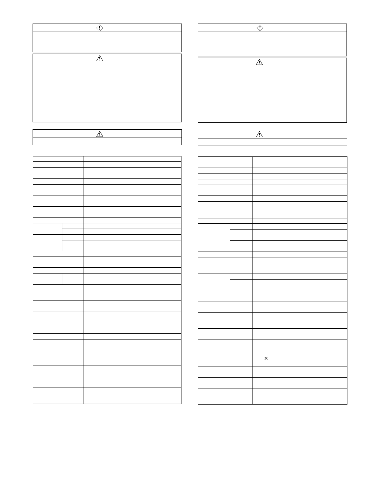
1. 仕様
項 目 内 容
出力点数 32 点
絶縁方式 フォトカプラ絶縁
定格負荷電圧 DC12/24V
使用負荷電圧範囲 DC10.2~31.2V(リップル率 5%以内)
最大負荷電流
0.5A/1 点
8A/1 コモン(2A/1 端子)
最大突入電流 1.2A 10ms 以下
OFF 時漏洩電流 0.1mA 以下
ON 時最大電圧降下
0.3V 以下(TYP.)0.5A,
0.6V 以下(MAX.)0.5A
出力形式 シンクタイプ
OFF→ON 0.5ms 以下
応答時間
ON→OFF 1.5ms 以下(抵抗負荷)
電圧 DC10.2~31.2V(リップル率 5%以内)
出力部
外部供給電源
電流
50mA 以下(DC 24V,全点 ON 時)
外部負荷電流は含まず
サージキラー ツェナーダイオード
コモン方式
32 点 1 コモン(4 点)(端子台形 1 線式)
占有局数 1 局 32 点割付け(32 点使用)
電圧 DC20.4~26.4V(リップル率 5%以内) I/O ユ ニ ッ ト
電源
電流 65mA 以下(DC24V,全点 ON 時)
ノイズ耐量
DC タイプのノイズ電圧 500Vp-p,
ノイズ幅 1µs,ノイズ周波数 25~60Hz のノイズシミュ
レータによる
耐電圧
DC 外部端子一括-アース間 AC500V 1 分間
絶縁抵抗
DC 外部端子一括-アース間 DC500V 絶縁抵抗計にて 10M
Ω以上
保護等級 IP2X
質量 0.7kg
外部接続方式
50 点端子台
[伝送回路,I/O ユニット電源,FG,入出力電源,I/O
信号]
M3.5×7 締付けトルク範囲:68~92N・㎝
適合圧着端子の挿入枚数は 2 枚以内
ユニット取付けネジ
平座金みがき丸付 M4 ネジ
(締付けトルク範囲:78~108N・cm)
適合圧着端子
R1.25-3.5(JIS C 2805 に準拠)
RAV2-3.5
別売部品
A6DIN1C,A2CCOM-TB
CC-Link システム小形タイプリモート I/O ユニット
ユーザーズマニュアル(詳細編)SH(名)3307 参照
【STARTING AND MAINTENANCE PRECAUTIONS】
DANGER
● Do not touch terminals when the power is on. Doing so could cause an electric
shock.
● Switch off all phases of the externally supplied power used in the system when
cleaning the module or retightening the terminal or module mounting screws. Not
doing so could result in electric shock.
CAUTION
● Never try to disassemble and modify module. It may cause product failure,
malfunction, fire or cause injury.
● Do not drop or apply any strong impact to the module. Doing so may damage the
module.
● Completely turn off the externally supplied power used in the system before
mounting or removing the module to/from the panel. Not doing so could result in
damage to the product.
● Mounting/removing the terminal block is limited to 50 times after using a product.
(IEC61131-2-compliant)
● Always make sure to touch the grounded metal to discharge the electricity charged
in the body, etc., before touching the module. Failure to do so may cause a failure or
malfunctions of the module.
【DISPOSAL PRECAUTIONS】
CAUTION
● When disposing of this product, treat it as industrial waste.
1. Specification
Item Description
Number of output points 32 points
Isolation method Photocoupler
Rated load voltage 12/24V DC
Operating load voltage range 10.2 to 31.2 V DC (ripple ratio: within 5 %)
Max. load current
0.5 A/point
8 A/common (2A/terminal)
Max. inrush current 1.2 A 10 ms or lower
Leakage current at OFF 0.1 mA or lower
Max. voltage drop at ON
0.3 V or lower (TYP.) 0.5 A,
0.6 V or lower (MAX.) 0.5 A
Output form Sink type
OFF→ON 0.5 ms or lower
Response time
ON→OFF 1.5 ms or lower (resistive load)
Voltage 10.2 to 31.2 V DC (ripple ratio: within 5 %)
External Power
supply for output
Current
50 mA or lower (When 24 V DC, all points on)
Not including external load current
Surge suppression Zener diode
Wiring method for common
32 points/common (4 points)
(terminal block 1-wire type)
Occupied station number 1 station 32 points assignment (use 32 points)
Voltage 20.4 to 26.4 V DC (ripple ratio: within 5 %) I/O module
power supply
Current 65 mA or lower (When 24 V DC, all points on)
Noise durability
DC type noise voltage 500 Vp-p,
noise width 1µs, noise carrier frequency 25 to 60 Hz
(noise simulator condition)
Withstand voltage
500 V AC for 1 minute between all DC external
terminals and ground
Insulation resistance
10 MΩ or higher, measured with a 500 V DC
insulation resistance tester between all DC external
terminals and ground
Protection of degree IP2X
Weight 0.7 kg
External wiring system
50-point terminal block
[transmission circuit, I/O module power supply, FG,
I/O power supply, I/O signal]
M3.5
7 Tightening torque range: 68 to 92 N・cm
Applicable solderless terminals: 2 max.
Module mounting screw
M4 screw with plain washer finished round
(tightening torque range: 78 to 108 N・cm)
Applicable solderless
terminal
R1.25 - 3.5 (JIS C 2805 conforming)
RAV2 - 3.5
Parts sold separately
A6DIN1C, A2CCOM-TB
Refer to CC-Link System Compact Type Remote
I/O Module User’s Manual SH(NA)4007
 Loading...