

Mitsubishi Electric AJ65BTS-RPH User Manual
CC-Link System
Spring Clamp Termnal Block Type
Repeater Hub Module
User’s Manual
AJ65BTS-RPH
Thank you for buying the Mitsubishi general-purpose programmable
logic controller MELSEC-A series.
Prior to use, please read both this manual and related manuals
thoroughly and familiarize yourself with the product.
MODEL AJ65BTS-RPH-U
MODEL
13JP97
CODE
IB(NA)-0800346-B(0612)MEE
© 2006 MITSUBISHI ELECTRIC CORPORATION

zSAFETY PRECAUTIONSz
(Read these precautions before using.)
When using Mitsubishi equipment, thoroughly read this manual and the
associated manuals introduced in this manual. Also pay careful attention to safety
and handle the module properly.
The precautions given in this manual are concerned with this product. Refer to the
user's manual of the network system to use for a description of the network
system safety precautions.
These SAFETY PRECAUTIONS classify the safety precautions into two
categories: “DANGER” and “CAUTION”.
Indicates that incorrect handling may cause hazardous
DANGER
conditions, resulting in death or severe injury.
Indicates that incorrect handling may cause hazardous
CAUTION
Depending on circumstances, procedures indicated by may also
be linked to serious results.
In any case, it is important to follow the directions for usage.
Store this manual in a safe place so that you can take it out and read it whenever
necessary. Always forward it to the end user.
conditions, resulting in medium or slight personal
injury or physical damage.
CAUTION
A-1
[DESIGN PRECAUTIONS]
DANGER
z Input/output could be switched on or off when a problem occurs in the
repeater module.
So build an external monitoring circuit that will monitor any input/output
signals that could cause a serious accident.
CAUTION
z Use the module in an environment that meets the general specifications
contained in this manual. Using this module in an environment outside the
range of the general specifications could result in electric shock, fire,
erroneous operation, and damage to or deterioration of the product.
z Do not install the control wires or communication cables together with the
main circuit or power wires.
Keep a distance of 100mm (3.94inch) or more between them.
Not doing so could result in malfunctions due to noise.
[INSTALLATION PRECAUTIONS]
CAUTION
z Do not directly touch the module's conductive parts.
Doing so may cause malfunctions or failure of the module.
z Fix the module securely with a DIN rail or screws, and when using screws,
tighten them within the specified torque range.
Undertightening can cause a drop, short circuit or malfunction. Overtightening
can cause a drop, short circuit or malfunction due to damage to the screw or
module.
A-2
[WIRING PRECAUTIONS]
DANGER
z Before installation or wiring, be sure to shut off all phases of the external
power supply used in the system.
If the power is not disconnected at all phases an electric shock or product
damage may result.
CAUTION
z Always earth the FG terminal to the protective earth conductor. Otherwise
there will be an electric shock or misoperation.
z Perform correct wiring for the module according to the product’s rated voltage
and terminal arrangement. Connecting to a power supply different from rating
or miss-wiring may cause fire and/or product failure.
z Ensure that no foreign matter such as chips and wire-offcuts enter the module.
Foreign matter can cause a fire, failure or malfunction.
z Be sure that the communication cable connected to the module is kept in the
duct or is fixed with cramps.
Failure to do so may cause a damage to the module or cables due to
dangling, shifting or inadvertent handling of cable, or malfunction because of
bad cable contacts.
z Do not install the control lines together with the communication cables, or
bring them close to each other. Failure to do so may cause malfunctions due
to noise.
z When disconnecting the communication and power supply cables from the
module, do not hold and pull the cable part.
Disconnect the cables after loosening the screws in the portions connected to
the module.
Pulling the cables connected to the module can damage the module and
cables or can cause a malfunction due to a cable connection fault.
A-3
[STARTING AND MAINTENANCE PRECAUTIONS]
CAUTION
z Do not disassemble or modify the modules.
Doing so could cause failure, erroneous operation, injury, or fire.
z Be sure to shut down all the phases of the externally supplied power used in
the system before cleaning the module, retightening the module fixing screws,
and attaching/removing the module.
Not doing so can cause the module to fail or malfunction.
z Do not install/remove the terminal block more than 50 times after the first use
of the product. (IEC 61131-2 compliant)
z Before handling the module, make sure to touch a grounded metal object to
discharge the static electricity from the human body.
Failure to do say cause a failure or malfunctions of the module.
[DISPOSAL PRECAUTIONS]
CAUTION
z When disposing of this product, treat it as industrial waste.
A-4
REVISIONS
* The manual number is given on the bottom right of the cover.
Print Date *Manual Number Revision
Oct., 2006 IB(NA)-0800346-A First edition
Dec., 2006 IB(NA)-0800346-B
Correction
SAFETY PRECAUTIONS, About the
Manual, Section 2.2, 2.3, 3.1, 3.2, 4.2.1
This manual confers no industrial property rights or any rights of any other kind,
nor does it confer any patent licenses. Mitsubishi Electric Corporation cannot be
held responsible for any problems involving industrial property rights which may
occur as a result of using the contents noted in this manual.
© 2006 MITSUBISHI ELECTRIC CORPORATION
A-5

CONTENTS
1. OVERVIEW ....................................................................................................1
1.1 Features ..................................................................................................1
2. SYSTEM CONFIGURATION .........................................................................3
2.1 Total configuration ...................................................................................3
2.2 Applicable system .................................................................................... 4
2.3 Cautions on system configuration ........................................................... 5
3. SPECIFICATION .........................................................................................12
3.1 General specifications ...........................................................................12
3.2 Performance specifications ................................................................... 14
3.3 Specifications of connection cable ........................................................17
3.4 Maximum transmission distance ........................................................... 18
4. PROCEDURE UP TO START OF DATA LINK ............................................19
4.1 Procedure up to start of data link ...........................................................19
4.2 Mounting and installation .......................................................................20
4.2.1 Cautions on handling .................................................................... 20
4.2.2 Installation environment ................................................................ 25
4.3 Names and settings of parts ..................................................................26
4.4 Connection of module through CC-Link dedicated cable ...................... 30
4.5 Check for state of connection (line test) ................................................ 31
5. TROUBLESHOOTING ................................................................................. 34
6. EXTERNAL DIMENSIONS ..........................................................................38
A-6
About the Manuals
The following manuals are also related to this product.
Order them if necessary.
Related Manual
Manual name
CC-Link System Master/Local Module Type AJ61BT11/
A1SJ61BT11 User’s Manual
CC-Link System Master/Local Module Type AJ61QBT11/
A1SJ61QBT11 User’s Manual
CC-Link System Master/Local Module User’s Manual
QJ61BT11N
CC-Link System Repeater (T-junction) Module Type
AJ65SBT-RPT User’s Manual
CC-Link System Optical Repeater Module Type AJ65SBTRPS/AJ65SBT-RPG User’s Manual
CC-Link System Space Optical Repeater Module Type
AJ65BT-RPI-10A/AJ65BT-RPI-10B User’s Manual
Manual No.
(Model code)
IB-66721
(13J872)
IB-66722
(13J873)
SH-080394E
(13JR64)
IB-0800078
(13JQ81)
IB-0800089
(13JQ85)
IB-0800090
(13JQ86)
CC-Link System Low Profile Waterproof Type Repeater
Hub Module User’s Manual
Compliance with the EMC and Low Voltage Directives
When incorporating the Mitsubishi PLC into other machinery or equipment and
keeping compliance with the EMC and low voltage directives, refer to Chapter 3,
"EMC Directives and Low Voltage Directives" of the User's Manual (Hardware)
included with the CPU module or base unit used.
The CE logo is printed on the rating plate of the PLC, indicating compliance with
the EMC and low voltage directives.
To conform this product to the EMC Directive and Low Voltage Directive, refer to
the Section of “CC-Link Modules” in Chapter 3 “EMC Directive and Low Voltage
Directive” of the User’s Manual (Hardware) of the CPU module used.
IB-0800288
(13JP55)
A-7

Abbreviated names, generic names and terms
Abbreviated names,
generic names and terms
AJ-65BTS-RPH
AJ65FBTA-RPH
AJ65SBT-RPT
AJ65SBT-RPS/RPG
AJ65BT-RPI-10A/10B
AJ65SBT-CLB
Segment
Description
Abbreviation of AJ65BTS-RPH type CC-Link system spring clamp
terminal Block type Repeater hub module.
Abbreviation of AJ65FBTA-RPH type CC-Link system low profile
waterproof type repeater hub module.
Abbreviation of AJ65SBT-RPT type CC-Link system repeater (Tjunction) module.
Abbreviation of AJ65SBT-RPS/AJ65SBT-RPG type CC-Link
system optical repeater module.
Abbreviation of AJ65BT-RPI-10A/AJ65BT-RPI-10B type CC-Link
system space optical repeater module.
Abbreviation of AJ65SBT-CLB CC-Link - CC-Link/LT bridge
module.
System between terminating resistors connected to each other
through cross-over cables.The conventional CC-Link system can be
said to be configured with one segment.
Master station
Local station
Remote I/O station
Remote device station
Remote station
Intelligent device station
Repeater
Standby master station
Slave station
Station to control the data link system. One station is required for
each system.
Station which has a sequencer CPU and can communicate with the
master station and the other local stations.
Remote station processing only information in unit of bit.
(AJ65BTB1-16D, AJ65SBTB1-16D, etc.)
Remote station processing only information in unit of bit and in unit
of word. (AJ65BT-64AD, AJ65BT-64DAV, AJ65BT-64DAI, etc.)
Generic name of remote I/O station and remote device station.
Controlled by the master station.
Station allowing transient transmission such as AJ65BT-R2.
(Including local stations)
Module for expanding the CC-Link system by connecting the
segments to each other.
Backup station which inherits data link control when the master
station comes off parallel due to error.
Generic term of remote I/O station, remote device station, local
station, intelligent device station, and standby master station.
Master local module
Generic name of QJ61BT11N, QJ61BT11, AJ61BT11,
A1SJ61BT11, AJ61QBT11 and A1SJ61QBT11.
A-8
Abbreviated names,
generic names and terms
Generic name of QJ61BT11N, QJ61BT11, AJ61BT11,
Master module
Local module
Intelligent device module Module allowing transient transmission such as AJ65BT-R2.
A1SJ61BT11, AJ61QBT11 and A1SJ61QBT11 when these are
used as the master station.
Generic name of QJ61BT11N, QJ61BT11, AJ61BT11,
A1SJ61BT11, AJ61QBT11 and A1SJ61QBT11 when these are
used as the local station.
Description
Product structure
The product structure of AJ65BTS-RPH is as shown below.
Product name Quantity
AJ65FBTA-RPH module 1
Terminating resistor kit 1
For a trunk line (Bar terminal type): 110Ω (brown,
brown, brown)
For a trunk line (Bar terminal type): 130Ω (brown,
orange, brown)
For a branch line (Y terminal type): 110Ω (brown,
brown, brown)
1
1
8
A-9
1. OVERVIEW
This User’s Manual describes the specifications, names of parts, and
settings of the AJ65BTS-RPH type CC-Link system spring clamp terminal
block type repeater hub module (hereafter abbreviated as AJ65BTS-RPH)
used in the CC-Link system.
1.1 Features
The AJ65BTS-RPH is the module designed for improving flexibility in
cable wiring of the CC-Link system.
Using the AJ65BTS-RPH allows the extension of the transmission
distance and star-topology wiring (with 8 branch lines) in the CC-Link
system.
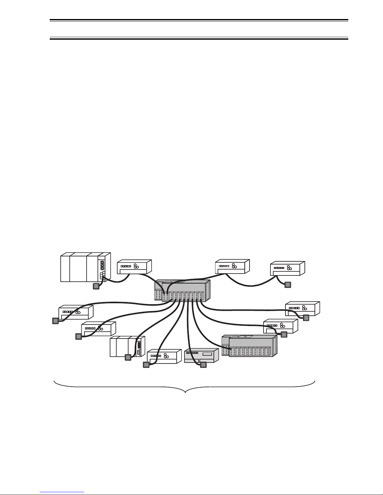
(1) Star-topology wiring (T-branch) with 8 branch lines (segments)
available in CC-Link system
By placing the AJ65BTS-RPH between modules of the CC-Link
system, star-topology wiring (T-branch) with up to 8 branch lines
Master station
Remote I/O
station
Remote device
station
(segments) can be used in the CC-Link system of all transmission
rates (10Mbps, 5Mbps, 2.5Mbps, 625kbps, and 156kbps).
Remote I/O
station
Local station
Repeater
(AJ65
Remote I/O
station
Intelligent device
BTS
-RPH)
IN
OUT
Repeater
(AJ65SBT-RPT)
station
Repeater
(
AJ65BTS-RPH
Remote device
station
Remote
device station
Intelligent device
station
)
Star-topology wiring with 8 branch lines can be used!!
1
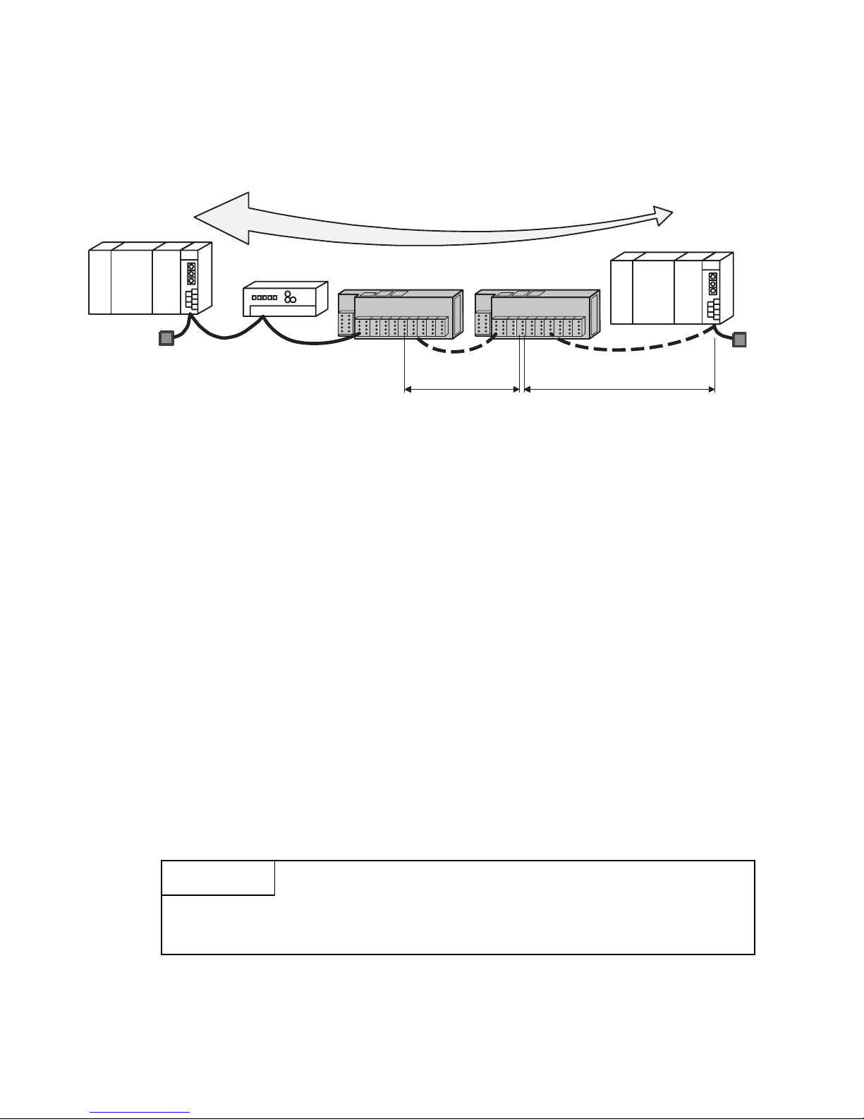
(2) Extended transmission distance in CC-Link system
Use of AJ65BTS-RPH enables the transmission distance of the CCLink system to be extended.
In addition, use of multiple modules enables the transmission
distance of the CC-Link system to be extended up to 2 stages.
Master station
*1 Max. transmission distance at a transmission speed of 156kbps.
*2 Though it is not shown here, the other remote stations can be
(3) Energy saving realized by adoption of a spring clamp terminal block
Extended to 3.6km (11811.02ft.) max !!
Remote I/O
station
Repeater (AJ65BTS-RPH)
*2
1st stage
*1
Remote
station
*2
2nd stage
connected between the repeaters.
(a) The AJ65BTS-RPH has adopted a spring clamp terminal block.
Because screw tightening is not needed, working steps can be
reduced.
(b) The terminal block can be installed to or removed from the
module, which reduces the maintenance cost and improves the
maintainability.
(c) All the operation and wiring parts are placed on the module front,
allowing easier operation and wiring.
(4) Improved maintenability by system separation
By using the AJ65BTS-RPH, any of the systems can be separated
and error location can be identified quickly.
This prevents the whole system from being seriously affected by an
error.
POINT
Branch lines with no error can send/receive data normally, not
influenced by each other.
2
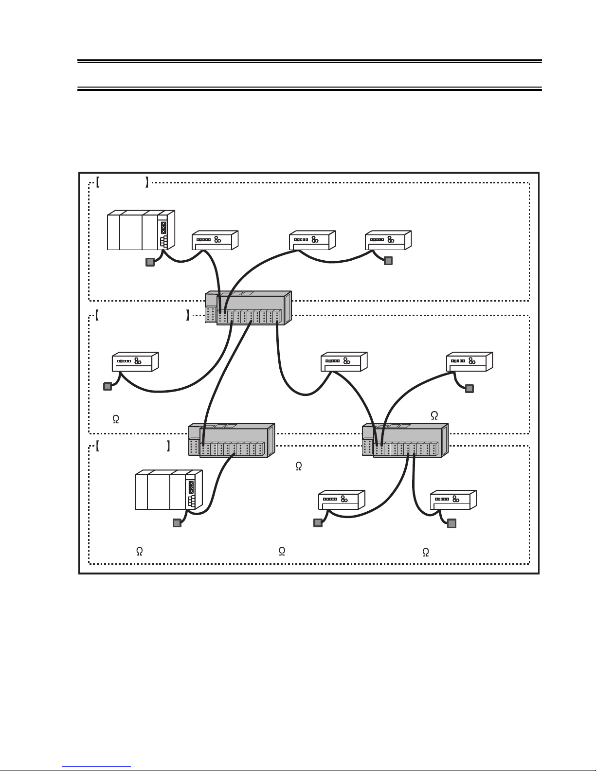
2. SYSTEM CONFIGURATION
2.1 Total configuration
The total configuration employed when the AJ65BTS-RPH is used is as
shown below.
Segment
Master station
*1
I/O station
Remote
Remote
device station
Intelligent
device station
Terminating resistor
(indispensable)
Segment (1st stage)
Remote
I/O station
Terminating rresistor,
110 (indispensable)
Segment (2nd stage)
Local station
Terminating resistor,
110 (indispensable)
*3
*2
*3
Terminating resistor
(indispensable)
Repeater (AJ65BTS-RPH)
Intelligent
device station
Repeater (AJ65BTS-RPH)
Terminating resistor,
110 (built-in)
Remote
I/O station
Terminating resistor,
110 (indispensable)
*3
*3
Remote
device station
Terminating resistor,
110 (indispensable)
Repeater (AJ65BTS-RPH)
Remote
device station
Terminating resistor,
110 (indispensable)
*3
*3
*1 The transmission speed of each segment must be matched with that
of the master station.
*2 2 stages of segments max. are allowed to be used.
*3 The 130Ω terminating resistor is not usable for a segment connected
on the branch line side of the AJ65BTS-RPH.
Use the 110Ω terminating resistor that is included with the AJ65BTS-
RPH.
3
2.2 Applicable system
This section describes usable modules and cables.
(1) Modules connectable on the branch line side
The types of the modules connectable on the branch line side of the
AJ65BTS-RPH are shown below.
Table 2.1 Modules connectable on the branch line side
Category Module types
Remote I/O station
Remote device station
Slave station
Intelligent device station
Local station
AJ65BTS-RPH
AJ65FBTA-RPH
Repeater
Bridge AJ65SBT-CLB
AJ65SBT-RPT
AJ65SBT-RPS/RPG
AJ65BT-RPI-10A/10B
(2) Applicable communication cables
The communication cables connectable to the AJ65BTS-RPH are
shown below.
Table 2.2 Applicable communication cables
Connector
name
Trunk line side
Branch line side
CC-Link version Name
Ver.1.00
Ver.1.10 CC-Link dedicated cable
Ver.1.00 CC-Link dedicated cable
Ver.1.10 CC-Link dedicated cable
Applicable cable
resistance
CC-Link dedicated
high-performance cable
CC-Link dedicated cable
Terminal
130Ω
110Ω
POINT
The master station and stand by master station can not be connected
to the branch line side.
4
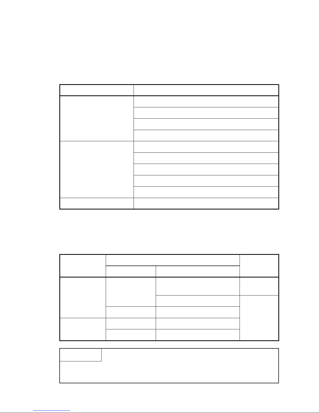
2.3 Cautions on system configuration
(1) Conditions of usable master module
When the AJ61BT11, A1SJ61BT11, AJ61QBT11 and A1SJ61QBT11
modules are used, those of the functional version B or later must be
employed. Use the master module bearing the version 9707 B or
later in the DATE column of the name plate as shown in the figure
below.
When the QJ61BT11N, QJ61BT11 module are used, any module
can be used irrespective of the version.
(a) Rating plate of AJ61BT11 or AJ61QBT11
PROGRAMMABLE CONTROLLER
DATE
yymm
MADE IN JAPAN BD992C077H01
B
Year and month of manufacture
(Use a master module of
9707 or later.)
Function version
Conformed standard
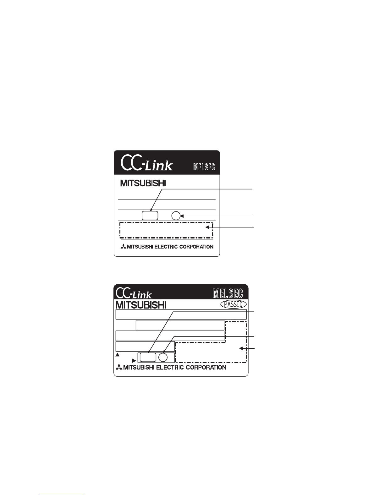
(b) Rating plate of A1SJ61BT11 or A1SJ61QBT11
Year and month of manufacture
MODEL
POWER
DATE
MADE IN JAPAN BD992C077H01
yymm
B
(Use a master module of
9707 or later.)
Function version
Conformed standard
5
 Loading...