

Page 1
CC-Link System Space Optical
Repeater Module
User’s Manual
(Hardware)
AJ65BT-RPI-10A/
AJ65BT-RPI-10B
Thank you for purchasing the programmable controller MELSEC
series.
Prior to use, please read this and relevant manuals thoroughly to
fully understand the product.
MODEL AJ65BT-RPI-10AB-U
MODEL
CODE
IB(NA)-0800090-K(1806)MEE
© 1999 MITSUBISHI ELECTRIC CORPORATION
13JQ86
Page 2
SAFETY PRECAUTIONS
WARNING
Indicates that incorrect handling may cause
hazardous conditions, resulting in death or severe
injury.
Indicates that incorrect handling may cause
hazardous conditions, resulting in minor or moderate
injury or property damage.
CAUTION
(Read these precautions before using this product.)
Before using this product, please read this manual and the relevant manuals
carefully and pay full attention to safety to handle the product correctly.
The precautions given in this manual are concerned with this product only. For the
safety precautions of the programmable controller system, refer to the user's
manual for the CPU module used.
In this manual, the safety precautions are classified into two levels:
" WARNING" and " CAUTION".
Under some circumstances, failure to observe the precautions given under
" CAUTION" may lead to serious consequences.
Observe the precautions of both levels because they are important for personal
and system safety.
Make sure that the end users read this manual and then keep the manual in a safe
place for future reference.
A-1
Page 3
[Design precautions]
WARNING
● Input/output could be switched on or off when a problem occurs in the
repeater module.
So build an external monitoring circuit that will monitor any input/output
signals that could cause a serious accident.
CAUTION
● Use each module in an environment as specified in the "general
specification" in the CPU module User's Manual.
Usage of the module outside the general specification range may cause
electric shock, fire, malfunction, product damage or deterioration.
● Do not have control cables and communication cables bundled with or
placed near by the main circuit and/or power cables.
Wire those cables at least 100mm(3.94 inch) away from the main circuit
and/or power cables.
It may cause malfunction due to noise interference.
[Installation precautions]
CAUTION
● Do not directly touch the module's conductive parts.
Doing so could cause malfunction or trouble in the module.
● Tighten the module securely using DIN rail or installation screws within the
specified torque range.
Loose terminal screws may cause falling, short circuit or erroneous
operation.
If the terminal screws are too tight, it may cause falling or short circuit due to
damage of the screws.
● When using multiple sets of the AJ65BT-RPI-10A/10B in line, provide shields
between the sets.
Not doing so can cause a malfunction due to interference.
● When using multiple sets of the AJ65BT-RPI-10A/10B in parallel, place the A
and B modules alternatively and keep a distance of at least 1m (3.28ft.).
Not placing them alternately can cause a malfunction due to interference.
A-2
Page 4
[Wiring Precautions]
WARNING
● Be sure to shut off all phases of the external power supply used by the
system before installation or wiring.
Not doing so can cause the product to be damaged or malfunction.
CAUTION
● Always ground the FG terminal to the protective ground conductor.
Otherwise there will be an electric shock or misoperation.
● Terminal screws which are not to be used must be tightened always.
Otherwise there will be a danger of short circuit against the bare solderless
terminals.
● Use applicable solderless terminals and tighten them with the specified
torque. If any solderless spade terminal is used, it may be disconnected
when the terminal screw comes loose, resulting in failure.
● Perform correct wiring for the module according to the product's rated
voltage and terminal arrangement. Connecting to a power supply different
from the rating or mis-wiring may cause fire and/or trouble.
● Fix terminal screws securely with the specified torque.
Loose terminal screws may cause short circuit or malfunction.
If the terminal screws are too tight, it may cause falling, short circuit or
erroneous operation due to damage of the screws or module.
● Make sure foreign objects do not get inside the module, such as dirt and wire
chips.
It may cause fire, trouble or malfunction.
● Be sure to fix wires or cables that are connected to the module in place,
either by running them through a duct or by using clamps.
If the cables are not fixed in one of these ways, dispersion, movement, or
careless pulling of the cables may cause damage to the module or cables, or
malfunction due to cable contact faults.
● Do not install the control lines together with the communication cables, or
bring them close to each other. Failure to do so may cause malfunctions due
to noise.
● When disconnecting a communication or power supply cable from the
module, do not pull on the cable itself.
Before disconnecting the cable from the terminal block, loosen off the screws
of the terminal block.
If you pull the cable connected to the module, the module or cable can be
damaged or misoperation can occur due to cable connection fault.
A-3
Page 5
[Startup and Maintenance Precautions]
WARNING
● Do not touch terminals when the power is on.
It may cause an electric shock or malfunction.
CAUTION
● For use in any environment where optical axis misalignment or the like is
expected due to lens surface contamination, vibration, impact or the like,
carry out periodic maintenance/inspection and improve the environment.
Not doing so can cause a malfunction.
● Never try to disassemble or modify module.
It may cause trouble, malfunction, injury or fire.
● The module case is made of resin; do not drop it or subject it to strong shock.
Module damage may result.
● Be sure to shut off all phases of the external power supply used by the
system before cleaning or retightening the terminal screws.
Not doing so can cause the module to fail or malfunction.
● Be sure to shut off all phases of the external power supply used by the
system before mounting or dismounting the module to or from the panel.
Not doing so can cause the module to fail or malfunction.
● Do not install/remove the terminal block more then 50 times after the first use
of the product. (IEC 61131-2 compliant)
● Always make sure to touch the grounded metal to discharge the electricity
charged in the body, etc., before touching the module.
Failure to do so may cause a failure or malfunctions of the module.
[Disposal Precautions]
CAUTION
● When disposing of this product, treat it as industrial waste.
A-4
Page 6
PRÉCAUTIONS DE SÉCURITÉ
AVERTISSEMENT
Attire l'attention sur le fait qu'une négligence peut
créer une situation de danger avec risque de mort
ou de blessures graves.
Attire l'attention sur le fait qu'une négligence peut
créer une situation de danger avec risque de
blessures légères ou de gravité moyennes ou
risque de dégâts matériels.
ATTENTION
(Lire ces précautions avant toute utilisation du produit.)
Avant d'utiliser ce produit, lire attentivement ce manuel ainsi que les manuels
auxquels il renvoie, et toujours considérer la sécurité comme de la plus haute
importance en manipulant le produit correctement.
Les précautions à observer figurant dans ce manuel ne concernent que ce
produit. Quant aux précautions de sécurité à observer pour le système du
contrôleur programmable, se reporter au manuel d'utilisation du module CPU
utilisé.
Dans ce manuel, les précautions de sécurité sont classées en deux niveaux, à
savoir : " AVERTISSEMENT" et " ATTENTION"
Dans certaines circonstances, le non-respect d'une précaution de sécurité
introduite sous le titre " ATTENTION"peut avoir des conséquences graves.
Les précautions de ces deux niveaux doivent être observées dans leur intégralité
car elles ont trait à la sécurité des personnes et aussi du système.
Veiller à ce que les utilisateurs finaux lisent ce manuel qui doit être conservé
soigneusement à portée de main pour s'y référer autant que de besoin.
A-5
Page 7
[Précautions lors de la conception]
AVERTISSEMENT
● Les entrées/sorties peuvent se trouver activées ou désactivées par
l'apparition d'un problème dans le module répéteur.
On doit donc constituer un circuit de surveillance externe pour le suivi des
signaux d'entrée/sortie qui pourraient être à l'origine d'accidents ou
d'incidents graves.
ATTENTION
● Utiliser chacun des modules dans un environnement conforme aux
"Spécifications générales" du manuel de l'utilisateur du module CPU.
L'utilisation du module dans un environnement ne respectant pas les
conditions prévues dans les spécifications générales peut entraîner une
électrocution, un départ de feu, des dysfonctionnements et une détérioration
du produit.
● Ne pas grouper ni placer à proximité les câbles de commande ou câbles de
communication avec les câbles des circuits principaux et/ou d'alimentation.
Installer ces câbles à une distance d'au moins 100mm (3,94 pouces) des
câbles des circuits principaux et/ou d'alimentation.
Cela pourrait produire des interférences à l'origine de dysfonctionnements.
A-6
Page 8
[Précautions d'installation]
ATTE NTION
● Éviter tout contact direct avec les parties conductrices du module.
Cela pourrait être à l'origine de dysfonctionnements ou autres problèmes
avec le module.
● Serrer le module fermement avec un rail DIN ou avec des vis de fixation
serrées dans les limites du couple de serrage prescrit.
Des vis de bornes desserrées peuvent tomber et être à l'origine de courtcircuits ou d'un fonctionnement erratique.
Un serrage excessif des vis de borne risque de les endommager ces vis
dont la chute risque de provoquer un court-circuit.
● Lors de l'utilisation de plusieurs ensembles AJ65BT-RPI-10A/10B en ligne,
fournissez des blindages entre les ensembles.
Faute de quoi, des interférences peuvent produire des dysfonctionnements.
● Quand on utilise plusieurs ensembles AJ65BT-RPI-10A/10B en ligne,
disposer en alternance un module A et un module B en maintenant une
distance minimum de 1m (3,28ft.).
Le non-respect de cette disposition en alternance peut produire des
interférences à l'origine de dysfonctionnement.
[Pécautions de câblage]
AVERTISSEMENT
● Avant installation ou câblage, toujours vérifier que les alimentations externes
utilisées par le système ont été coupées sur toutes les phases.
Faute de quoi, il y a risque d'endommagement ou de dysfonctionnement du
produit.
A-7
Page 9
ATTENTION
● Toujours mettre à la masse la borne FG sur le conducteur de protection de
terre.Autrement, il y aurait risque d'électrocution ou de dysfonctionnement.
● Toutes les vis des bornes inutilisées doivent être serrées.
Autrement, il y aurait risque de court-circuit par contact sur les bornes sans
soudure nues.
● Utiliser des bornes sans soudure de type approprié en les serrant dans les
limites du couple de serrage prescrit. Une borne sans soudure dont la vis se
desserre peut être une source de mauvais contact avec risque de panne.
● Effectuer le câblage du module correctement, en respectant la tension
nominale et l'affectation des bornes du produit. Le raccordement à une
source d'alimentation électrique différente de celle prescrite ou une erreur de
câblage peut être à l'origine d'un départ de feu et/ou d'un
dysfonctionnement.
● Bien serrer les vis de borne au couple de serrage prescrit.
Des vis de bornes desserrées peuvent être à l'origine de court-circuits ou de
dysfonctionnements.
Un serrage excessif peut endommager le module ou les vis qui risquent de
tomber et de provoquer un court-circuit ou un fonctionnement erratique.
● Veiller à ce qu'aucun objet ou impureté, débris de fil ou autres, ne pénètre
dans le module.
Cela peut être à l'origine d'un départ de feu, d'une panne ou d'un
dysfonctionnement.
● Veillez à installer correctement les câbles ou fils connectés au module, soit
en les faisant passer dans un conduit soit en utilisant des colliers de fixation.
Si les câbles ne sont pas fixés d'une façon ou d'une autre, la dispersion ou le
déplacement des câbles ou une traction exercée par inadvertance sur un
câble pourrait endommager le module ou les câbles et créer un mauvais
contact à l'origine de dysfonctionnements.
● Ne pas installer les lignes de commande et les câbles de communication
avec les lignes des circuits principaux ou de l'alimentation, et ne pas les
placer à proximité les uns des autres. Faute de quoi, les bruits parasites
produiront des dysfonctionnements.
● Pour enlever un câble d'alimentation ou de communication du module, ne
pas tirer sur le câble proprement dit.
Avant de débrancher le câble de la plaque à bornes, desserrer les vis de la
plaque à bornes.
Tirer sur un câble raccordé au module peut endommager le module ou le
câble et entraîner des dysfonctionnements par mauvais contact.
A-8
Page 10
[PRÉCAUTIONS DE MISE EN SERVICE ET DE MAINTENANCE]
AVERTISSEMENT
● Ne pas toucher aux bornes quand l'appareil est sous tension.
Cela pourrait être à l'origine d'une électrocution ou d'un dysfonctionnement.
ATTE NTION
● Pour l'utilisation dans un environnement où la contamination des lentilles, les
vibrations, les chocs, etc. risquent d'entraîner un dérèglement des axes
optiques, effectuer régulièrement les opérations de maintenance/inspection
périodique et apporter des améliorations à l'environnement.
Faute de quoi, il y a risque de dysfonctionnement.
● Ne jamais tenter de démonter ou modifier le module.
Il y aurait risque de panne, dysfonctionnement, blessure ou départ de feu.
● Le boîtier du module est en matière plastique; ne pas faire tomber le module
ou le soumettre à des chocs violents.
Il pourrait en résulter une détérioration du module.
● Ne pas oublier de couper toutes les phases de l'alimentation externe utilisée
par le système avant le nettoyage ou le resserrage des vis de bornes.
Faute de quoi, il y a risque de panne ou de dysfonctionnement du module.
● Ne pas oublier de couper toutes les phases de l'alimentation externe utilisée
par le système avant de mettre le module en place dans le tableau ou de l'en
retirer.
Faute de quoi, il y a risque de panne ou de dysfonctionnement du module.
● Après la première utilisation du produit, le nombre maximum admissible
d'opérations de pose/retrait du bornier est de 50. (selon IEC 61131-2)
● Avant de toucher le module, toujours se décharger de la charge
électrostatique dont le corps est porteur en touchant un objet métallique mis
à la terre.
Faute de quoi, il y a risque de panne ou de dysfonctionnements du module.
[PRÉCAUTIONS DE MISE AU REBUT]
ATTE NTION
● Lors de sa mise au rebut, ce produit doit être traité comme un déchet
industriel.
A-9
Page 11

CONDITIONS OF USE FOR THE PRODUCT
(1) Mitsubishi programmable controller ("the PRODUCT") shall be used in
conditions;
i) where any problem, fault or failure occurring in the PRODUCT, if any,
shall not lead to any major or serious accident; and
ii) where the backup and fail-safe function are systematically or
automatically provided outside of the PRODUCT for the case of any
problem, fault or failure occurring in the PRODUCT.
(2) The PRODUCT has been designed and manufactured for the purpose of
being used in general industries.
MITSUBISHI SHALL HAVE NO RESPONSIBILITY OR LIABILITY
(INCLUDING, BUT NOT LIMITED TO ANY AND ALL RESPONSIBILITY
OR LIABILITY BASED ON CONTRACT, WARRANTY, TORT, PRODUCT
LIABILITY) FOR ANY INJURY OR DEATH TO PERSONS OR LOSS OR
DAMAGE TO PROPERTY CAUSED BY the PRODUCT THAT ARE
OPERATED OR USED IN APPLICATION NOT INTENDED OR
EXCLUDED BY INSTRUCTIONS, PRECAUTIONS, OR WARNING
CONTAINED IN MITSUBISHI'S USER, INSTRUCTION AND/OR SAFETY
MANUALS, TECHNICAL BULLETINS AND GUIDELINES FOR the
PRODUCT.
("Prohibited Application")
Prohibited Applications include, but not limited to, the use of the PRODUCT
in;
• Nuclear Power Plants and any other power plants operated by Power
companies, and/or any other cases in which the public could be
affected if any problem or fault occurs in the PRODUCT.
• Railway companies or Public service purposes, and/or any other cases
in which establishment of a special quality assurance system is
required by the Purchaser or End User.
• Aircraft or Aerospace, Medical applications, Train equipment, transport
equipment such as Elevator and Escalator, Incineration and Fuel
devices, Vehicles, Manned transportation, Equipment for Recreation
and Amusement, and Safety devices, handling of Nuclear or
Hazardous Materials or Chemicals, Mining and Drilling, and/or other
applications where there is a significant risk of injury to the public or
property.
A-10
Page 12

Notwithstanding the above, restrictions Mitsubishi may in its sole discretion,
authorize use of the PRODUCT in one or more of the Prohibited
Applications, provided that the usage of the PRODUCT is limited only for
the specific applications agreed to by Mitsubishi and provided further that
no special quality assurance or fail-safe, redundant or other safety features
which exceed the general specifications of the PRODUCTs are required.
For details, please contact the Mitsubishi representative in your region.
A-11
Page 13
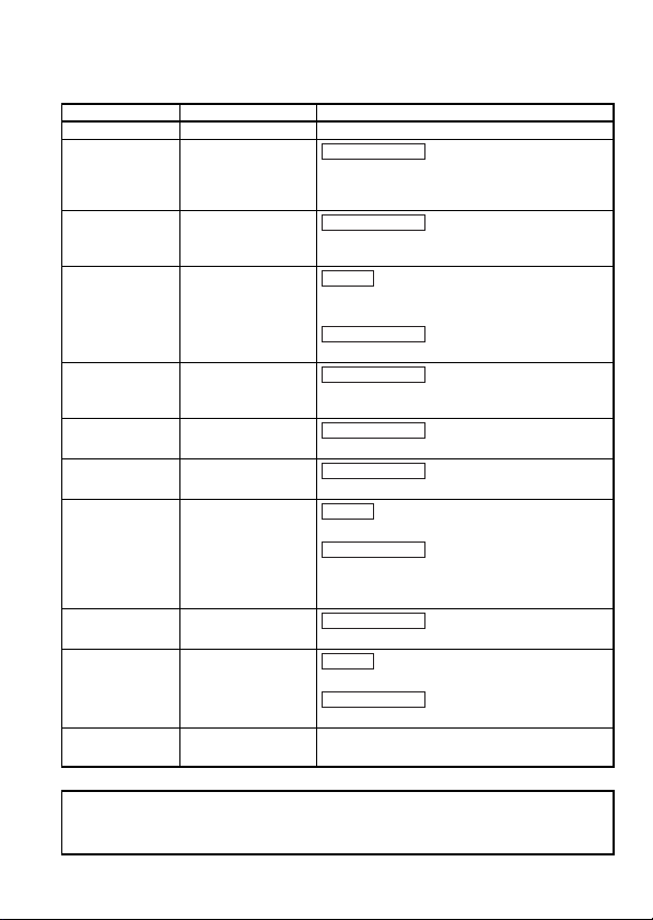
REVISIONS
Addition
Partial correction
Addition
Addition
*The manual number is given on the bottom right of the cover.
Print date *Manual number Revision
Nov.,1999 IB (NA)-0800090-A First edition
Feb.,2001 IB (NA)-0800090-B
Jun.,2003 IB (NA)-0800090-C
Jul.,2005 IB (NA)-0800090-D
Dec.,2006 IB (NA)-0800090-E
Jun.,2007 IB (NA)-0800090-F
Aug.,2007 IB (NA)-0800090-G
Dec.,2011 IB (NA)-0800090-H
Jul.,2014 IB (NA)-0800090-I
Dec., 2016 IB (NA)-0800090-J
Jun.,2018 IB (NA)-0800090-K
Partial correction
Change specified torque range of Display window
mounting screw from 32 to 5.8N/cm on
Section 4.2.1(1)
Partial correction
SAFETY PRECAUTIONS, About the Manuals,
Chapter 1, Se ction 1.3, 2.2, 3.1, 3.2, 4.2.1, 4.6
Conformation to the EMC Directive and Low
Voltage Instruction
Partial correction
SAFETY PRECAUTIONS
Partial correction
SAFETY PRECAUTIONS, About the Manuals,
Section 1.3, 2.2, 3.1, 3.2, 3.4, 4.2.1
Section 4.3,Contact address (Back cover)
Partial correction
Section 4.3
CONDITIONS OF USE FOR THE PRODUCT
Partial correction
SAFETY PRECAUTIONS, About the Manuals,
COMPLIANCE WITH EMC AND LOW VOLTAGE
DIRECTIVES, Section 3.1, 4.2.1, 4.5
Partial correction
About the Manuals, Section 1.3, 2.2, 4.3
SAFETY PRECAUTIONS (French)
Partial correction
Section 3.1, 4.2.1, 4.5
Descriptions are revised due to compliance with
the Chinese standardized law.
This manual confers no industrial property rights or any rights of any other kind, nor does it
confer any patent licenses. Mitsubishi Electric Corporation cannot be held responsible for any
problems involving industrial property rights which may occur as a result of using the contents
noted in this manual.
© 1999 MITSUBISHI ELECTRIC CORPORATION
A-12
Page 14

CONTENTS
1. OVERVIEW .................................................................................................... 1
1.1 Features ................................................................................................... 1
1.2 Packaged parts ........................................................................................ 3
1.3 Abbreviated names, generic names and terms ........................................ 4
2. SYSTEM CONFIGURATION.......................................................................... 5
2.1 Total configuration .................................................................................... 5
2.2 Cautions on system configuration ............................................................ 7
3. SPECIFICATIONS........................................................................................ 13
3.1 General specifications ............................................................................ 13
3.2 Performance specifications .................................................................... 15
3.3 Specifications of connection cables ....................................................... 16
3.4 Max. transmission distance .................................................................... 16
3.5 List of I/O Signals from/to the Master Module ........................................ 17
4. PROCEDURE UP TO START OF DATA LINK ........................................... 18
4.1 Procedure up to start of data link ........................................................... 18
4.2 Mounting and installation........................................................................ 19
4.2.1 Cautions on handling ...................................................................... 19
4.2.2 Installation environment .................................................................. 21
4.3 Names and settings of parts................................................................... 21
4.4 Setting of switches ................................................................................. 24
4.5 Connection of module through CC-Link dedicated cable ....................... 26
4.6 Optical axis adjustment .......................................................................... 28
4.6.1 Precautions for optical axis adjustment .......................................... 28
4.6.2 Optical axis adjustment method ...................................................... 29
4.6.3 Adjustment procedures for interference light .................................. 30
4.7 Check for state of connection (line test) ................................................. 32
5. ABOUT THE MONITOR FUNCTION............................................................ 34
6. TROUBLESHOOTING.................................................................................. 35
7. EXTERNAL DIMENSIONS DIAGRAM ......................................................... 36
A-13
Page 15
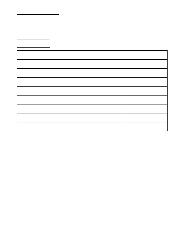
ABOUT MANUALS
The following manuals are related to this product.
Referring to this list, please request the necessary manuals.
Related Manual
Manual name
CC-Link System Master/Local Module Type AJ61BT11/A1SJ61BT11
User's Manual
CC-Link System Master/Local Module Type
AJ61QBT11/A1SJ61QBT11 User's Manual
MELSEC-Q CC-Link System Master/Local Module User's Manual
MELSEC-L CC-Link System Master/Local Module User’s Manual
CC-Link System Repeater (T-junction) Module User’s Manual
AJ65SBT-RPT
CC-Link System Optical Repeater Module User's Manual
CC-Link System Low Profile Waterproof Type Repeater Hub Module
User’s Manual AJ65FBTA-RPH
CC-Link System Spring Clamp Terminal Block Type Repeater Hub
Module User’s Manual AJ65BTS-RPH
COMPLIANCE WITH EMC AND LOW VOLTAGE
(1) Method of ensuring compliance
To ensure that Mitsubishi programmable controllers maintain EMC
and Low Voltage Directives when incorporated into other
machinery or equipment, certain measures may be necessary.
Please refer to one of the following manuals.
• User's manual for the CPU module or head module used
• Safety Guidelines (this manual is included with the CPU
module, base unit, or head module)
The CE mark on the side of the programmable controller indicates
compliance with EMC and Low Voltage Directives.
Manual Number
(Model code)
IB-66721
(13J872)
IB-66722
(13J873)
SH-080394E
(13JR64)
SH-080895ENG
(13JZ41)
IB-0800078
(13JQ81)
IB-0800089
(13JQ85)
IB-0800288
(13JP55)
IB-0800346
(13JP97)
(2) Additional measures
To ensure that this product maintains EMC and Low Voltage
Directives, please refer to one of the manuals listed under (1).
A-14
Page 16
1. OVERVIEW
This User's Manual describes the specifications, part names, settings
and others of the AJ65BT-RPI-10A/10B type CC-Link system space
optical repeater module (hereafter abbreviated to the AJ65BT-RPI10A/10B) used in a CC-Link system.
1.1 Features
The AJ65BT-RPI-10A/10B is a module used to expand the CC-Link
system.
By using the AJ65BT-RPI-10A and AJ65BT-RPI-10B in combination,
infrared space transmission, increased transmission distance and Tjunction wiring can be achieved in a CC-Link system (at the
transmission speed of 2.5Mbps, 625kbps or 156kbps only).
Also, the optical axis adjustment can be made easily because the light
receiving status of the module can be transmitted to the master station.
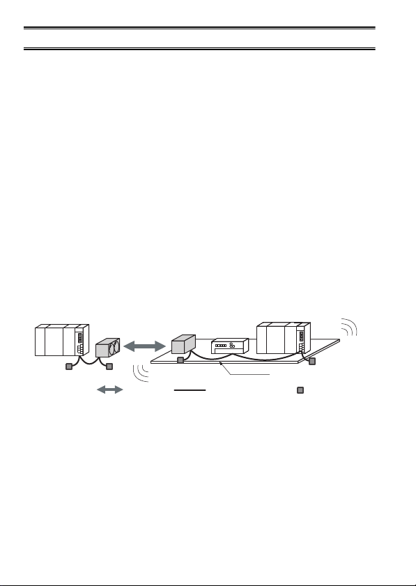
(1) Infrared space transmission
Using these modules enables infrared space transmission of 0 to
100m (0 to 327.87ft.).
This makes a CC-Link system usable in places where cabling is
difficult.
Master station
Repeater
Repeater
Remote station
Local station
Space
transmission
CC-Link dedicated cable
Movable
Termination resistor
(required)
[Places where cabling is difficult]
• Place where a movable range is wide
• Place where the number of movable times is large and cables
may be broken due to fatigue
• Place where you want to minimize the number of movable parts,
e.g. cable bearers, for dust proof purpose (such as a clean
room)
1
Page 17
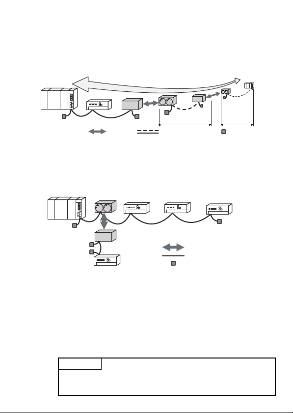
(2) Increased transmission distance
Using these modules increases the transmission distance of a CCLink system.
Also, using multiple sets of these modules allows the transmission
distance to be increased by up to two stages.
Master station
Remote I/O station
Space
transmission
*1 Max. transmission distance at the transmission speed setting of 156kbps.
*2 Though omitted here, another remote station may be connected between repeaters.
Increased up to 3.8km!!
Repeater
*2
1st stage 2nd stage
CC-Link dedicated cable
(3) T-junction wiring enabled in CC-Link system
T-junction wiring can be performed by arrangement of these
modules between the modules of a CC-Link system.
Master station
T-junction wiring
enabled!!
Repeater
Repeater
Remote I/O station
Remote
I/O station
Intelligent
device station
Space transmission
CC-Link dedicated cable
Termination resistor (required)
(4) Communication status of the module can be monitored
The light receiving status of the module can be monitored
(imported to the master station) by setting the station numbers to
these modules and also making the remote I/O station-equivalent
parameter setting in the master station.
Also, the imported receiving status of the mating module can be
indicated by the LEDs of the own module using the sequence
program of the master station, ensuring ease of fine adjustment of
the optical axes.
*1
device station
Remote
Remote
station
*2
Termination resistor
(required)
POINT
Station number and parameter settings are not needed when these modules are
used as repeaters only, i.e. the light receiving status is not monitored (monitor
function is not used).
2
Page 18

1.2 Packaged parts
After unpacking, make sure that those parts listed below are packaged.
(1) AJ65BT-RPI-10A
AJ65BT-RPI-10A module 1
Terminating resistances 110 1/2W (Brown, Brown, Brown) 1
Terminating resistances 130 1/2W (Brown, Orange, Brown) 1
(2) AJ65BT-RPI-10B
AJ65BT-RPI-10B module 1
Terminating resistances 110 1/2W (Brown, Brown, Brown) 1
Terminating resistances 130 1/2W (Brown, Orange, Brown) 1
Part name Quantity
Part name Quantity
3
Page 19

1.3 Abbreviated names, generic names and terms
Abbreviated names, generic names and terms Description
Abbreviated names,
generic names and terms
AJ65BT-RPI-10A/10B
AJ65SBT-RPT
AJ65SBT-RPS/RPG
AJ65FBTA-RPH
AJ65BTS-RPH
A module
B module
Segment
Master station
Local station
Remote I/O station
Remote device station
Remote station
Intelligent device station
Repeater
Ready master station
Built-in CC-Link function
Master local module
Master modu le
Local module
Remote module
Intelligent device module Module allowing transient transmission such as AJ65BT-R2.
Abbreviation of AJ65BT-RPI-10A/AJ65BT-RPI-10B type CC-Link
system space optical repeater module
Abbreviation of AJ65SBT-RPT type CC-Link system repeater (Tjunction) module.
Abbreviation of AJ65SBTRPS/AJ65SBT-RPG type CC-Link system
optical repeater module.
Abbreviation of AJ65FBTA-RPH type CC-Link system low profile
waterproof type repeater hub module.
Abbreviation of AJ65BTS-RPH type CC-Link system spri ng clamp
terminal block type repeater hub module.
Abbreviation of AJ65BT-RPI-10A type CC-Link system space
optical repeater module
Abbreviation of AJ65BT-RPI-10B type CC-Link system space
optical repeater module
System between terminating resistances connected to each other
through cross-over cables.The conventional CC-Link system can
be said to be configured with one segment (Refer to Section 2.1.).
Station to control the data link system. One station is required for
each system.
Station which has a sequencer CPU and can communicate with the
master station and the other local stations.
Remote station processing only information in unit of bit.
(AJ65BTB1-16D, AJ65SBTB1-16D, AJ65SBTB1-8 , etc.)
Remote station processing only information in unit of bit and in unit
of word.(AJ65BT-64AD, AJ65BT-64DAV, AJ65BT-64DAI, etc.)
Generic name of remote I/O station and remote device station.
Controlled by the master station.
Station allowing transient transmission such as AJ65BT-R2.
(Including local stations)
Module for expanding the CC-Link system by connecting the
segments to each other.
Backup station which inherits data link control when the master
station comes off parallel due to error.
Abbreviation of built-in CC-Link system master/local functions of the
L26CPU-BT and L26CPU-PBT
Generic name of RJ61BT11, QJ61B T11N, QJ61BT11, built-in CCLink function, AJ61BT11, A1SJ61BT11, AJ61QBT11, and
A1SJ61QBT11
Generic name of the master local module that is used as a master
station
Generic name of the master local module that is used as a local
station
Generic name of AJ65BTB1-16D, AJ65SBTB1-16D,
AJ65BT-64AD, AJ65BT-64DAV, AJ65BT-64DAI and A852GOT.
Description
4
Page 20

2. SYSTEM CONFIGURATION
2.1 Total configuration
The total configuration employed when the AJ65BT-RPI-10A/10B
module is used is as shown below.
[Segment]
Remote I/O
station
*2
Remote I/O
station
device station
Local station
*3
Remote I/O station
Space
transmission
Remote
(the A or B module)
*1
Repeater
(the B or A module)
Intelligent
device station
Remote I/O
station
Remote I/O station
CC-Link dedicated cable
Intelligent
device station
*1
Remote
device station
*1
Repeater
(the A or B module)
Repeater
(the B or A module)
*1
RepeaterRepeater
(the A or B module)
Repeater
(the B or A module)
*1
Termination resistor
(required)
*1
Master station
[Segment (1st stage)]
[Segment (1st stage)]
[Segment (2nd stage)]
*1 The A and B modules must be used in pairs.
*2 The transmission speed of each segment must be matched with that of the
master station (2.5Mbps, 625kbps, 156kbps).
*3 Up to two stages of segments may be used.
5
Page 21

(1) What is a repeater?
This is the module for expanding the CC-Link system by connecting
the segments to each other.
(2) What is a segment?
In the CC-Link system where repeaters are used, the equipment
included between terminating resistances connected to each other
through cross-over cables is generally called the segment.
6
Page 22

2.2 Cautions on system configuration
(1) About the combination of modules used
Always use the AJ65BT-RPI-10A/10B in such a configuration that
the lens surfaces of the A and B modules are opposed.
There are no restrictions on the sequence of connections.
(Either the A or B module may be placed on the master station
side.)
(2) Conditions of usable master module
When the AJ61BT11, A1SJ61BT11, AJ61QBT11 and
A1SJ61QBT11 modules are used, those of the functional version B
or later must be employed. Use the master module bearing the
version 9707 B or later in the DATE column of the name plate as
shown in the figure below.
Year and month
of manufacture
Function version
Year and month
of manufacture
Function version
(3) Max. number of modules connected to configure CC-Link system
Up to 64 modules of repeaters can be connected in one segment.
In the CC-Link system where repeaters are used, also the number
of remote stations capable of being controlled by one master
station is the same as in the other systems.
For details, refer to the User's Manual of the applicable master
module.
(When the monitor function is used in these modules, they must be
counted not as repeaters but as remote I/O stations.)
7
Page 23

3.8km
(12459.02ft.)
Max.
transmission
distance
Space transmission
Remote
station
Transmission speed: 156kbps setting
Repeater
Master
station
Segment
Max. 1200m (3934.43ft.)
Max. 100m (327.87ft.)
Segment (1st stage)
Max. 1200m (3934.43ft.)
Segment (2st stage)
Max. 1200m (3934.43ft.)
Space transmission
Max. 100m (327.87ft.)
(4) Max. number of stages connected to configure segment
These modules may be used to communicate with a remote station
up to two segments away from the segment of the master station.
(5) Instructions for using different models of repeaters in combination
Note that when combining the repeaters of different models, there
are the following restrictions on the number of connectable
repeaters and the number of connected stages.
Combination
pattern
AJ65BTS
-RPH
1)
2)
3)
4) — — 2 4(2 set) — —4
1—2———
—1 2———
1 — — 2(1set) — —
1———2(1 set)—
— 1 — 2(1 set) — —
—1——2(1 set)—
1————2(1 set)
—1———2(1 set)
5) — — 2 — 2(1 set) —
6) — — 2 — — 2(1 set)
7) — — — 2(1 set) 2(1 set) —
9) 1 1 — — — —
— — — 2(1 set) — 2(1 set)
————2(1 set)2(1 set)
Max. number of repeaters
AJ65FBT
A-RPH
AJ65SBT
-RPH
AJ65SBT
8
-RPS
AJ65SBT
-RPG
AJ65BT
-RPI
-10A/10B
number
of stages
Max.
3
2
3
28)
Page 24

POINT
• For the CC-Link system, up to 2 repeater types can be used in combination. Using 3
models or more is not allowed.
• When repeaters are connected in the same segment by link wiring, up to 64 modules can
be connected.
For details, refer to the user's manual of the master module used.
Ex.) A CC-Link system with combination pattern 7) is built
Master station
Segment
Segment
1st stage
Segment
2nd stage
Segment
3rd stage
AJ65BT-RPI
AJ65FBTA-RPH
For combination pattern 6),
4 (2 sets) or more AJ65BT-RPIs
are not connectable.
Up to 64 modules can be
connected in a segment.
AJ65BT-RPI
Remote station
9
Page 25

(a) Combination pattern 1) (c) Combination pattern 3)
Master station
AJ65BTS-RPH or
AJ65FBTA-RPH
One module
AJ65SBT-RPT
Up to two modules
Remote station
Segment
Segment
1st stage
OUTIN
Segment
2nd stage
OUTIN
Segment
3rd stage
Master station
AJ65BTS-RPH or
AJ65FBTA-RPH
One module
AJ65BT-RPI
Two modules
(one set)
Remote station
(b) Combination pattern 2) (d) Combination pattern 4)
Master station
AJ65BTS-RPH or
AJ65FBTA-RPH
One module
AJ65SBT-RPS or
AJ65SBT-RPG
Two modules
(one set)
Remote station
Segment
Segment
1st stage
Segment
2nd stage
Master station
AJ65SBT-RPT
Up to two modules
AJ65SBT-RPS
Four modules
(two sets)
or
Two modules
(one set)
Segment
Segment
1st stage
Segment
2nd stage
Segment
OUTIN
Segment
1st stage
OUTIN
Segment
2nd stage
Segment
3rd stage
10
Remote station
Segment
4th stage
Page 26

(e) Combination pattern 1) (g) Combination pattern 3)
Master station
AJ65SBT-RPT
Up to
two modules
AJ65SBT-RPG
Two modules
(one set)
Remote station
Segment
OUTIN
Segment
1st stage
OUTIN
Segment
2nd stage
Segment
3rd stage
Master station
AJ65SBT-RPS
Two modules
(one set)
AJ65SBT-RPG
Two modules
(one set)
Remote station
(f) Combination pattern 2) (h) Combination pattern 4)
Master station
AJ65SBT-RPT
Up to
two modules
AJ65SBT-RPI
Two modules
(one set)
Remote station
Segment
OUTIN
Segment
1st stage
OUTIN
Segment
2nd stage
Segment
3rd stage
Master station
AJ65SBT-RPS or
AJ65SBT-RPG
Two modules
(one set)
AJ65SBT-RPI
Two modules
(one set)
Remote station
Segment
Segment
1st stage
Segment
2nd stage
Segment
Segment
1st stage
Segment
2nd stage
11
Page 27

(h) Combination pattern 1)
A
Master station
AJ65BTS-RPH
One module
J65FBTA-RPH
One module
Remote station
Segment
Segment
1st stage
Segment
2nd stage
12
Page 28

3. SPECIFICATIONS
3.1 General specifications
This section provides specifications of the AJ65BT-RPI-10A/10B
module used.
Item Specifications
Operating
ambient
tempera ture
Température
ambiante de
fonctionnement
Storage a mbient
tempera ture
Operating
ambient humidity
Storage a mbient
humidity
Under
intermittent
vibration
Under
continuous
vibration
Compliant with JIS B 3502, IEC 61131-2
(490 m/s2, 10 times each in 3 directions X, Y, Z)
10000 lx max. (no exposure to direct sunlight)
*3
Compliant
with JIS B
3502 and
IEC 61131-2
Vibration
resistance
Shock
resistance
Operating
atmosphere
Ambient
illumination
Cooling method Self-cooling method
Operating
*4
altitude
Installation
location
Overvoltage
*1
category
Pollution degree
*2
0 to 50°C
0 à 50 °C
-25 to 75°C
10 to 90%RH, non-condensing
Frequency
5 to 8.4Hz ——— 3.5mm 10 times
8.4 to
150Hz
5 to 8.4Hz ——— 1.75mm
8.4 to
150Hz
No corrosive gases
acceleration
0 to 2000m
Indoor
II or less
2 or less
Constant
9.8m/s2———
4.9m/s2———
Half
amplitude
Sweep
count
each in
X, Y, Z
directions
———
13
Page 29

*1 This indicates the section of the power supply to which the equipment is
assumed to be connected between the public electrical power distribution
network and the machinery within premises. Category II applies to
equipment for which electrical power is supplied from fixed facilities. The
surge voltage withstand level for up to the rated voltage of 300 V is 2500 V.
*2 This index indicates the degree to which conductive material is generated in
terms of the environment in which the equipment is used. Pollution level 2 is
when only non-conductive pollution occurs. A temporary conductivity caused
by condensing must be expected occasionally.
*3 The reference values of ambient illumination (in JIS Z 9110) are indicated
below.
• Illumination needed for fine visual work in factories : 3000 to 1500 lx
• Illumination needed for work in offices : 2000 to 750 lx
*4 Do not use or store the programmable controller under pressure higher than
the atmospheric pressure of altitude 0m. Doing so may cause malfunction.
When using the programmable controller under pressure, please consult
your local Mitsubishi Electric representative.
14
Page 30

3.2 Performance specifications
The following table lists the performance specifications of the AJ65BTRPI-10A/10B.
Item Specifications
Voltage 20.4 to 26.4VDC
Power
supply
Common
specifications
CC-Link
communication
specifications
Optical
communication
specifications
Current 137mA (at TYP. 24VDC)
Noise immunity
Dielectric withstand
voltage
Insulation
resistance
Weight 0.5kg
Transmission
speed
Max. number of
segments
connected
Max. transmission
distance of each
segment
Max. number of
connected modules
Number of stations
occupied
Optical
transmission
distance
Orientation angle
Modulation
frequency
Modulation system FSK
Simulator noise of 500Vp-p, obtained by a noise simulator
of 1µs noise width and 25 to 60Hz noise frequency
500VAC for 1 minute between all DC external terminals
and ground
10M or higher, measured with a 500VDC insulation
resistance tester
Can be selected from among 156kbps, 625kbps and
2.5Mbps.
AJ65BT-RPI only (Refer to Section 2.2 (4)) 2stages
Combination of AJ65BT-RPI and AJ65SBTRPT (Refer to Section 2.2 (5))
Combination of AJ65BT-RPI and one of
AJ65SBT-RPS, AJ65 SBT-RPG,
AJ65FBTARPH, or AJ65BTS-RPH. (Refer to
Section 2.2 (5))
Depending on the transmission speed.
(Refer to the user's manual of the master module used.)
64 (Refer to Section 2.2 (3) for the conditions of the
number of modules connected.)
When using monitor function : 1station
When not using monitor function : 0station
(Refer to Chapter 5 for details of the monitor function.)
0 to 100m (0 to 327.87ft.)
Optical transmission distance of 0 to 50m
(0 to 163.94ft.) : Full angle 2°
Optical transmission distance of 50 to 100m
(163.94 to 327.87ft.) : Full angle 1°
A module to B module: 36±3MHz
B module to A module: 44±2.5MHz
3stages
2stages
15
Page 31

3.3 Specifications of connection cables
Remarks
Use the CC-Link dedicated cable for the CC-Link system. If a cable
other than the CC-Link dedicated cable is used, the performance of the
CC-Link system cannot be guaranteed.
For the specifications of the CC-Link dedicated cables or any other
inquires, visit the following site:
CC-Link Partner Association website: http://www.cc-link.org/
For details, refer to the CC-Link cable wiring manual issued by the CCLink Partner Association.
3.4 Max. transmission distance
Master
station
Repeater
Remote
station
Transmission speed: 156kbps setting
Segment
Max. 1200m (3934.43ft.)
Space transmission
Max. 100m (327.87ft.)
Segment (1st stage)
Max. 1200m (3934.43ft.)
Space transmission
Max. 100m (327.87ft.)
Segment (2nd stage)
Max. 1200m (3934.43ft.)
Conditions Description
The maximum transmission distance in each segment is the same as
that in normal CC-Link system (system configured with one segment
only).
Transmission speed
Max. number of stages
connected to
configure segment
The maximum transmission distance in each segment varies
according to the transmission speed.
For details, refer to the User's Manual of the applicable master module.
(The length of the cables between repeater stations is treated in the
same manner as in the remote I/O station.)
When one connection stage is added, the maximum transmission
distance is added by an amount equivalent to one segment.
16
Max.
transmission
distance
3.8km
(12459.02ft.)
Page 32

3.5 List of I/O Signals from/to the Master Module
The following tables provide the I/O signals transferred from/to the
master module when the monitor function is used in the AJ65BT-RPI10A/10B.
Refer to Chapter 5 for details of the monitor function.
Refer to Section 4.3 for the definitions of the operation indicator LEDs
used to explain the signals.
(1) Input signals (AJ65BT-RPI-10A/10B to master module)
Input
Signal
RXn0 RC status ON indicates that the module is ready to receive data.
RXn1 R1 status
RXn2 R2 status
RXn3 R3 status
RXn4 to
RX(n+1)F
* Value based on the RC status signal (1 time).
Output Signal
Ryn0 to RYnF —— Must not be used.
RY(n+1)0 SC ON Lights up the "SC" operation indicator LE D.*
RY(n+1)1 S1 ON Lights up the "S1" operation indicator LED.*
RY(n+1)2 S2 ON Lights up the "S2" operation indicator LED.*
RY(n+1)3 S2 ON Lights up the "S3" operation indicator LED.*
RY(n+1)4 to
RX(n+1)F
* The RC, R1, R2 and R3 status signals of the mating module can be indicated
Signal
Name
ON indicates that the allowance of the light receiving level is 1.5
times or higher *.
ON indicates that the allowance of the light receiving level is 2.0
times or higher *.
ON indicates that the allowance of the light receiving level is 2.5
times or higher *.
—— Must not be used.
Description
(2) Output signals (Master module to AJ65BT-RPI-10A/10B)
Signal
Name
—— Must not be used.
Description
by the operation indicator LEDs of the own module using the sequence
program of the master station, ensuring ease of optical axis adjustment.
17
Page 33

4. PROCEDURE UP TO START OF DATA LINK
4.1 Procedure up to start of data link
The procedure ranging from the installation of the AJ65BT-RPI-10A/10B
module to the start of data link is described below.
Start
Install the AJ65BT-RPI-10A/10B module.
Set the switches of the module.
Refer to Section 4.2.
Refer to Section 4.4.
Connect the modules using CC-Link
dedicated cables.
Make AJ65BT-RPI-10A/10B(A module
B module) adjustment of the optical axes.
Check for the connection conditions
of the modules (line test).
Start the system.
Completion
POINT
The procedure described here is for the AJ65BT-RPI-10A/10B module only.
In order for you to understand the procedure of the entire CC-Link system, refer to the User's
Manual of the applicable master module.
18
Refer to Section 4.5.
Refer to Section 4.6.
Refer to Section 4.7.
Refer to the User's Manual
of the applicable master module.
Page 34

4.2 Mounting and installation
4.2.1 Cautions on handling
Cautions on handling the AJ65BT-RPI-10A/10B module are described
below.
(1) Tighten screws (such as a module fixing screw) within the
tightening torque range specified in the table below. Do not overtighten these screws. The screws and module case may be
damaged.
Module mounting screw (M6 thread with finished
circular flat washer)
Display window mounting screw (M2.6 thread) 0.058N•m
Terminal block screw (M3 thread)
Vis de plaque à bornes (filetage M3)
Terminal block mounting screw (M3.5 thread) 0.68 to 0.98N•m
(2) When mounting the AJ65BT-RPI-10A/10B, it has no specific
mounting orientation as a module alone. However, it should be
mounted with its top face placed in the same orientation as that of
the mating module with which optical communication is made.
When these modules are mounted in opposite orientations, they
must be mounted more than 1m(3.28ft.) away from each other.
Top face
Screw location Specified torque range
1.2N•m
0.59 to 0.88N•m
0,59 à 0,88 N•m
Top face
[Top faces set in the opposite orientations][Top faces set in the same orientation]
Top face
0 to 100m
(0 to 327.87ft.)
More than 1m
(3.28ft.)away
19
Top face
Page 35

(3) When using multiple sets of the AJ65BT-RPI-10A/10B in line,
provide shields between the sets. Not doing so can cause a
malfunction due to interference.
Shield needed
(4) When using multiple sets of the AJ65BT-RPI-10A/10B in parallel,
place the A and B modules alternatively and keep a distance of at
least 1m (3.28ft.). Not placing them alternately can cause a
malfunction due to interference.
Referring to the figure showing the relation between the optical
communication distance and the distance from the other system,
adjust the optical axis to remove the influence of interference light.
(Refer to Section 4.6.3.)
B moduleA module
1m (3.28ft.)
at least
8
4
1
Distance from other system (m)
0
Install modules alternately and keep
a distance of at least 1m (3.28ft.)
Adjustment for interference
light not required
Not used
Optical communication distance (m)
A moduleB module
Adjustment
for interference
light required
(Worst-case value *2)
Adjustment for
interference light
required (Normal value *1)
10050100
*1 A value obtained when the optical axis of each system is adjusted to nearly
the center of the area in which the operation indicator LED, R3 turns on.
*2 A value obtained when the optical axis of the system is slanted toward the
other system.
20
Page 36

4.2.2 Installation environment
For installation environment, refer to Section 3.1 (General
Specifications).
4.3 Names and settings of parts
This section explains the part names, LED indication definitions, and
switch and control setting methods of the AJ65BT-RPI-10A/10B.
8) 8)
10)
Expanded view
8)5)
2)
3)
4)
No. Name Application
Operation
1)
Check for the module condition by observing the state of lighting of the LED.
LED
Name
PW
LRUNONOFF: :
indicator
LEDs
LERR
ERR
10)
8) 8) 8)
9)
1)
6)
Application
O N
Indicates that power is ON.
OFF : :
Indicates that power is OFF.
Indicates normal communication when the monitor function is
used.
Indicates that a communication error occurred when the
monitor function is used or that the monitor function is not
used.
ON
:
Indicates that a communication error occurred when the
monitor function is used or that the monitor function is not
used.
OFF
:
Indicates normal communication when the monitor function is
used.
ON
Indicates a communication error.
OFF: :
Indicates a normal status.
21
7)
Expanded
view
Page 37

No. Name Application
Operation
1)
indicator LEDs
Transmission
2)
speed setting
switch
Check for the module condition by observing the state of lighting of the
LED.
LED
Name
ON
:
Indicates that data is being sent to the connection cable
SD1
SD2
RD1
RD2
SC
S1
S2
S3
RC
R1
R2
R3
Used to set the transmission speed of the module. (Factory setting: 0)
0
1
2
3to 9
side.
OFF
:
Indicates that data is not sent to the connection cable
side.
ON
Indicates that data is being sent to the light output side.
OFF : :
Indicates that data is not sent to the light output side.
ON
:
Indicates that data is being received from the
connection cable side.
OFF
:
Indicates that data is not received from the connection
cable side.
Indicates that data is being received from the light input
ON
:
side.
Indicates that data is not received from the light input
OFF
:
side.
ON
Indicates that RY(n+1)0 is ON.
OFF::
Indicates that RY(n+1)0 is OFF.
ON
Indicates that RY(n+1)1 is ON.
OFF::
Indicates that RY(n+1)1 is OFF.
ON
Indicates that RY(n+1)2 is ON.
OFF::
Indicates that RY(n+1)2 is OFF.
ON
Indicates that RY(n+1)3 is ON.
OFF::
Indicates that RY(n+1)3 is OFF.
ON
Indicates that the own module is enabled for light
receiving.
OFF::
Indicates that the own module is disabled for light
receiving.
ON
Indicates that the light receiving level allowance of the
own module is 1.5 times or more.
OFF::
Indicates that the light receiving level allowance of the
own module is less than 1.5 times (based on RC).
ON
Indicates that the light receiving level allowance of the
own module is 2.0 times or more.
OFF::
Indicates that the light receiving level allowance of the
own module is less than 2.0 times (based on RC).
ON
Indicates that the light receiving level allowance of the
own module is 2.5 times or more.
OFF::
Indicates that the light receiving level allowance of the
own module is less than 2.5 times (based on RC).
: 156kbps
: 625kbps
: 2.5Mbps
: Must not be set.
Application
Lit only when the
monitor function is
used.
Refer to Chapter 5
for details of the
monitor function.
22
Page 38

No. Name Application
Station number
3)
setting switch
(Tens)
Station number
4)
setting switch
(Units)
5) Lens surfaces Used to make optical communication.
6) Terminal block Used to connect the power supply cable and CC-Link dedicated cables.
Termination
7)
resistor switch
Module
8)
mounting
screws
Mounting
9)
bracket
Display window
10)
mounting
screws
POINT
The settings of the transmission speed setti ng switch and station number setting switches
are made valid when the module power is switched from OFF to ON. If any switch setting
has been changed with the module power ON, perform the above operation again.
Used to set the station number of the module.
Also used to set whether the monitor function is used or not. (Factory
setting: 0)
00 : Monitor function is not used
01 to 64
65 to 99::
Used to set whether the built-in termination resistor (110) of the
module is used or not. (Factory setting: OFF)
ON : Used
OFF: Not used
Used to fix the module to the mounting bracket.
Mounting bracket
Used to mount the module.
Used to fix the display window to the module.
The display window is removed when switch setting is to be made.
Station number when monitor function is used
Must not be set.
23
Page 39

4.4 Setting of switches
The setting of the switches on the AJ65BT-RPI-10A/10B module is
described below.
(1) Transmission speed setting switch
This switch is used to set the transmission speed of the AJ65BTRPI-10A/10B module.
For detail of the setting, refer to Section 4.3.
POINT
• Set to the same state of setting as set in the master station.
• The states of setting of the transmission speed setting switch obtained when
the module power supply is set from OFF to ON or the reset switch is set to
OFF become effective. When the states of setting are changed with the
module power supply turned ON, perform the above operations again.
(2) Station number setting switches
The station number setting switches are used to set the station
number of the AJ65BT-RPI-10A/10B. It is also used to set whether
the monitor function is used or not. For full information on the
setting, refer to Section 4.3. For full information on the monitor
function, refer to Chapter 5.
POINT
The setting of the station number setting switches is made valid when the
module power is switched from OFF to ON. If the setting has been changed with
the module power ON, perform the above operation again.
24
Page 40

(3) Termination resistor switch
The termination resistor switch is used to set whether the built-in
termination resistor (110) of the AJ65BT-RPI-10A/10B is used
(ON) or not (OFF). Set this switch to the ON (used) position when
the AJ65BT-RPI-10A/10B is located on either side of the segment
and the accessory termination resistor is not used.
POINT
• In either of the following cases, do not use the built-in termination resistor
(110) of the AJ65BT-RPI-10A/10B but use the accessory termination
resistor.
1) When the 130 termination resistor is needed.
2) There is a possibility of removing the AJ65BT-RPI-10A/10B without
affecting the other stations for maintenance or other purpose.
When the built-in termination resistor is used, removing the terminal
block from the module makes the termination resistor disconnected,
disabling the other stations from making normal communication.
• Do not use the built-in termination resistor and accessory termination resistor
of the AJ65BT-RPI-10A/10B at the same time.
Doing so makes the module doubly provided with the termination resistors,
disabling normal communication.
25
Page 41

4.5 Connection of module through CC-Link dedicated cable
Raccordement du câble dédié CC-Link de traversée de
module
The method of connecting the AJ65BT-RPI-10A/10B module to the CCLink system through the CC-Link dedicated cable is shown below.
La méthode de connexion d'un module AJ65BT-RPI-10A/10B à un
système CC-Link par câble dédié CC-Link est représentée
schématiquement ci-après.
cable
cable
Remote module
(Blue)
(White)
(Yellow)
(Blue)
(White)
(Yellow)
Local module
Transmission
Terminating
resistor
Master module
DA
DB
DG
SLD
FG
(Blue)
(White)
(Yellow)
CC-Link dedicated
cable
Terminating
resistor
AJ65BT-RPI-10A/10B
(Blue)
(Blue)
DA
(White)
(Yellow)
DB
DG
(White)
(Yellow)
SLD
FG
Lens
surfaces
Space transmission
Lens
surfaces
(Blue)
DA
(White)
DB
(Yellow)
DG
SLD
CC-Link dedicated
CC-Link dedicated
FG
AJ65BT-RPI-10A/10B
English French English French
Master module Module maître
Space
transmission
Remote module Module distant Local module Module local
Terminating
resistor
CC-Link
dedicated cable
Lens surfaces
Résistance
d'extrémité
Câble dédié pour
CC-Link
Surfaces des
lentilles
Blue Bleu
White Blanc
Yellow jaune
DA
DB
DG
SLD
FG
DA
DB
DG
SLD
FG
spatiale
Terminating
resistor
Terminating
resistor
26
Page 42

Important
Important
In each segment, ensure to use the same type of CC-Link dedicated cables.
If different types of cables are used, normal data transmission will not be
assured.
Sur chaque segment, s'assurer qu'on utilise des câbles dédiés CC-Link du
même type.
Si les câbles utilisés sont de types différents, la transmission normale des
données ne peut être garantie.
POINT
POINT
• Ensure to connect the terminating resistances to both end modules of each
segment. In addition, connect them between DA and DB (DA1-DB1 and DA2DB2 for AJ65BT-RPI-10A/10B).
(The terminating resistances are furnished with the module.)
• The terminating resistances vary according to the type of cables in use.
For detail, refer to the User's Manual of the applicable master module.
• Connect the shield cable of the CC-Link dedicated cable to "SLD" of each
module, and ground both ends of the cable through "FG" to a class-D (class
3) ground.
SLD and FG are wired to each other inside the module.
• Ne pas oublier de raccorder la résistance terminale aux deux modules
d'extrémité sur chaque tronçon.De plus, établir la connexion entre DA et DB
(DA1-DB1 et DA2-DB2 pour AJ65BT-RPI-10A/10B).
(Les résistances terminales sont fournies avec le module.)
• Les résistances terminales diffèrent en fonction du type des câbles utilisés.
Pour le détail, voir le Manuel de l'utilisateur du module maître concerné.
• Raccorder le câble de blindage du câble dédié CC-Link sur "SLD" de chaque
module, et mettre à la terre les deux extrémi tés du câble via "FG" sur une terre
prise de terre de classe D (classe 3).
SLD et FG sont câblés entre eux à l'intérieur du module.
27
Page 43

4.6 Optical axis adjustment
4.6.1 Precautions for optical axis adjustment
For the optical axis adjustment, pay attention to the following.
(1) Adjust the optical axis of each system to the center of the light
receiving level area as much as possible. (Refer to Section 4.6.2.)
When multiple sets of the AJ65BT-RPI-10A/10B are used in
parallel, turn off the other system(s) before starting the optical axis
adjustment.
(2) When the AJ65BT-RPI-10A/10B is installed to a movable body,
check that the adjusted position in the light receiving level is not
lowered during movement.
(3) When multiple sets of the AJ65BT-RPI-10A/10B are used in
parallel, check that the individual system is not affected by
interference light from the other system. (Refer to Section 4.6.3.)
28
Page 44

4.6.2 Optical axis adjustment method
The optical axis is adjusted in the following steps.
(1) Place the modules face-to-face and align the module axes
approximately.
(2) While observing the operation indicator LEDs of the module (A
module), change the angle of the other module (B module) in
vertical or horizontal directions to obtain a proper angular range in
which the operation indicator LED, R3 turns on.
Note that, if A module is moved at this time, the reference axis
cannot be fixed and proper adjustment will be difficult.
(3) Check the operation indicator LEDs on both modules.
Confirming the LEDs on one module only may not adjust the other
optical axis.
(a) Vertical angle adjustment
R
A module
B module
Fix the module and check
the operation indicator
LED, R3 turns on.
(b) Horizontal angle adjustment
R
A module
Fix the module and check
the operation indicator
LED, R3 turns on.
29
Adjust the angle.
B module
Adjust the angle.
Page 45

4.6.3 Adjustment procedures for interference light
The following is the adjustment procedures for interference light emitted
from the other system.
(1) Influence of interference light between module A1 and A2
(a) Turn on the module A1 and A2 only and turn off the module B1
and B2.
(b) Check for influence of interference light emitted from A1 to A2
1) When the operation indicator LED, R1 of A2 is off:
No influence of interference light is identified.
2) When the operation indicator LED, R1 of A2 is on:
The influence of interference light is identified.
Readjust the optical axis of module A1 by making it away
from the system (2).
(c) Check for influence of interference light emitted from A2 to A1
1) When the operation indicator LED, R1 of A1 is off:
No influence of interference light is identified.
2) When the operation indicator LED, R1 of A1 is on:
Influence of interference light is identified.
Readjust the optical axis of module A2 by making it away
from the system (1).
Check that
R1 is off.
R
System
(1)
System
(2)
Module B2
(OFF)
Interference
light
Module B1Module A1
(OFF)(ON)
Module A2
(ON)
R
Check that
R1 is off.
30
Page 46

(2) Influence of interference light between module B1 and B2
(a) Turn on the module B1 and B2 only and turn off the module A1
and A2.
(b) Check for influence of interference light emitted from B1 to B2
1) When the operation indicator LED, R1 of B2 is off:
No influence of interference light is identified.
2) When the operation indicator LED, R1 of B2 is on:
The influence of interference light is identified.
Readjust the optical axis of module B1 by making it away
from the system (2).
(c) Check for influence of interference light emitted from B2 to B1
1) When the operation indicator LED, R1 of B1 is off:
No influence of interference light is identified.
2) When the operation indicator LED, R1 of B1 is on:
The influence of interference light is identified.
Readjust the optical axis of module B2 by making it away
from the system (1).
R
Check that
R1 is off.
Check that
R1 is off.
System
(1)
(OFF)
R
System
(2)
Module B1Module A1
(ON)
Interference
light
Module A2Module B2
(OFF)(ON)
31
Page 47

4.7 Check for state of connection (line test)
After connecting all modules including the AJ65BT-RPI-10A/10B, check
whether the CC-Link system can establish proper data links or not.
To perform the line test of the AJ65BT-RPI-10A/10B module, use the
line test 2 of the master module. For the line test 2 of the master
module, refer to the User's Manual of the applicable master module.
Perform the test following the steps shown below.
32
Page 48

Completion
NO
NO
NO
Normal
NO
Normal
Normal
YES
NO
YES
YES
YES
YES
Start
Set the test switch to OFF
(normal operation).
After checking the input power supply
voltage, turn on the power supply.
Perform the line test 2 of the master
module. In this test, use any one
station connected to the downstream side of
the AJ65BT-RPI-10A/10B (side where the
master station does not exist).
Does the master
module complete the line
test 2 normally?
Does "PW" light up?
Does "ERR." go off?
Do "RD1" and
"SD2" light up?
Do "RD2" and
"SD1" light up?
Refer to the User's Manual of
the applicable master module.
...................
The hardware may have a defect. Contact
the nearest sales office , and explain the
error symptom and get advice.
Check that the transmission speed is set
correctly.
Check that the wiring is normal.
Check that there is no defective station in the
CC-Link system.
Check that cables, power supplies and
modules are arranged properly so that
excessive noise is not emitted.
Check that the transmission speed is set
correctly.
Check that the wiring on the IN side is
normal.
Check that the master station is normal.
Check that the transmission speed is set
correctly.
Check that optical communication is proper.
Check that the master station is set so that it
can communicate with the remote station to
be tested.
Check that the remote station to be tested
is normal.
Check that the other stations are normal.
Check the combination of the maximum
transmission distance, setting of transmission
speed, and station-to-station cables.
33
Page 49

5. ABOUT THE MONITOR FUNCTION
The monitor function allows the receiving status (RC, R1, R2, R3)
indicated by the operation indicator LEDs of the AJ65BT-RPI-10A/10B
to be monitored (imported to the master station). To use the monitor
function, the station numbers must be set and parameter setting to the
master station must also be made as remote I/O stations. For the way to
make parameter setting, refer to the user's manual of the master
module used.
Also, the imported receiving status of the mating module can be
indicated by the "SC, S1, S2, S3" operation indicator LEDs of the own
module using the sequence program of the master station, ensuring
ease of optical axis adjustment. Refer to Section 3.5 for the I/O signals
transferred to/from the master module.
POINT
• Make fine adjustment of the optical axes by adjusting the orientation of the
own module until the receiving status of the mating module is maximized.
Using the monitor functi on allows the receiving status of the mating module to
be checked on the own module, ensuring ease of fine adjustment of the optical
axes.
• Since the monitor function transmits the receiving status through CC-Link data
link, the modules must at least be ready to receive lights (the "RC" operation
indicator LEDs are lit) each other.
34
Page 50

6. TROUBLESHOOTING
Any error during data link can be checked by the ERR. LED of the
master station.
If the ERR. LED of the master station is lit or flickers due to a data link
error, first refer to the user's manual of the master module used and
check the data link states of the other stations in the CC-Link system.
If there are many stations in data link error on the downstream side of
the AJ65BT-RPI-10A/10B (the side on which the master station does
not exist), the AJ65BT-RPI-10A/10B may be faulty. Therefore, make a
line test again (refer to Section 4.7).
Master station
Repeater
Repeater
Remote
I/O station
Intelligent
device station
device station
Remote
Downstream side of
AJ65SBT-RPI-10A/10B
Remote
I/O station
Intelligent
device station
Perform a line test!
35
Remote
device station
Page 51

7. EXTERNAL DIMENSIONS DIAGRAM
Unit : mm (inch)
3- 7 x 16 mounting hole (M6 mounting screw)
7 mounting hole (M6 mounting screw)
42
2.0 (0.08)
128.0 (5.04)
12.0
(0.47)
35.5
(1.40)
8.0
(0.32)
100.0 (3.94)
84.0 (3.31)
40.0 (1.58)
161.0 (6.34)
145.0 (5.71)
130.0 (5.12)
45.0 (1.77)
44.0 (1.73)
57.5 (2.27)
Optical axis adjusting
angle 4° up/down
and side-to-side
35.5 (1.40)
The external dimensions diagram of the AJ65BT-RPI-10A/10B module
is shown below.
36
Page 52

MEMO
37
Page 53

Page 54

WARRANTY
Mitsubishi will not be held liable for damage caused by factors found not to be the cause of
Mitsubishi; machine damage or lost profits caused by faults in the Mitsubishi products; damage,
secondary damage, accident compensation caused by special factors unpredictable by
Mitsubishi; damages to products other than Mitsubishi products; and to other duties.
Country/
Sales office/
Region
Tel
USA MITSUBISHI ELECTRIC AUTOMATION, INC.
500 Corporate Woods Parkway, Vernon Hills, IL
60061, U.S.A.
Tel : +1-847-478-2100
Mexico MITSUBISHI ELECTRIC AUTOMATION, INC.
Mexico Branch
Mariano Escobedo #69, Col. Zona Industrial,
Tlalnepantla Edo. Mexico, C.P.54030
Tel : +52-55-3067-7500
Brazil MITSUBISHI ELECTRIC DO BRASIL COMÉRCIO
E SERVIÇOS LTDA.
Avenida Adelino Cardana, 293, 21 andar,
Bethaville, Barueri SP, Brazil
Tel : +55-11-4689-3000
Germany MITSUBISHI ELECTRIC EUROPE B.V. German
Branch
Mitsubishi-Electric-Platz 1, 40882 Ratingen,
Germany
Tel : +49-2102-486-0
UK MITSUBISHI ELECTRIC EUROPE B.V. UK Branch
Travellers Lane, Hatfield, Hertfordshire, AL10 8XB,
U.K.
Tel : +44-1707-28-8780
Ireland MITSUBISHI ELECTRIC EUROPE B.V. Irish
Branch
Westgate Business Park, Ballymount, Dublin 24,
Ireland
Tel : +353-1-4198800
Italy MITSUBISHI ELECTRIC EUROPE B.V. Italian
Branch
Centro Direzionale Colleoni-Palazzo Sirio Viale
Colleoni 7, 20864 Agrate Brianza(Milano) Italy
Tel : +39-039-60531
Spain MITSUBISHI ELECTRIC EUROPE, B.V. Spanish
Branch
Carretera de Rubí, 76-80-Apdo. 420, 08190 Sant
Cugat del Vallés (Barcelona), Spain
Tel : +34-935-65-3131
France MITSUBISHI ELECTRIC EUROPE B.V. French
Branch
25, Boulevard des Bouvets, 92741 Nanterre Cedex,
France
Tel : +33-1-55-68-55-68
Czech
MITSUBISHI ELECTRIC EUROPE B.V. Czech
Republic
Branch
Avenir Business Park, Radlicka 751/113e, 158 00
Praha5, Czech Republic
Tel : +420-251-551-470
Poland MITSUBISHI ELECTRIC EUROPE B.V. Polish
Branch
ul. Krakowska 50, 32-083 Balice, Poland
Tel : +48-12-347-65-00
Sweden
MITSUBISHI ELECTRIC EUROPE B.V.
(Scandinavia)
Fjelievägen 8, SE-22736 Lund, Sweden
Tel : +46-8-625-10-00
Russia MITSUBISHI ELECTRIC (RUSSIA) LLC St.
Petersburg Branch
Piskarevsky pr. 2, bld 2, lit “Sch”, BC “Benua”, office
720; 195027 St. Petersburg, Russia
Tel : +7-812-633-3497
HEAD OFFICE : TOKYO BUILDING, 2-7-3 MARUNOUCHI, CHIYODA-KU, TOKYO 100-8310, JAPAN
NAGOYA WORKS : 1-14, YADA-MINAMI 5-CHOME, HIGASHI-KU, NAGOYA, JAPAN
When exported from Japan, this manual does not require application to the Ministry of Economy,
Trade and Industry for service transaction permission.
Sales office/
Country/
Tel
Region
Turkey
MITSUBISHI ELECTRIC TURKEY A.Ş Ümraniye
Branch
Serifali Mahallesi Nutuk Sokak No:5, TR-34775
Umraniye/Istanbul, Turkey
Tel : +90-216-526-3990
UAE
MITSUBISHI ELECTRIC EUROPE B.V. Dubai
Branch
Dubai Silicon Oasis, P.O.BOX 341241, Dubai,
U.A.E.
Tel : +971-4-3724716
South
ADROIT TECHNOLOGIES
Africa
20 Waterford Office Park, 189 Witkoppen Road,
Fourways, South Africa
Tel : +27-11-658-8100
China
MITSUBISHI ELECTRIC AUTOMATION (CHINA)
LTD.
No.1386 Hongqiao Road, Mitsubishi Electric
Automation Center, Shanghai, China
Tel : +86-21-2322-3030
Taiwan
SETSUYO ENTERPRISE CO., LTD.
6F, No.105, Wugong 3rd Road, Wugu District, New
Taipei City 24889, Taiwan
Tel : +886-2-2299-2499
Korea
MITSUBISHI ELECTRIC AUTOMATION KOREA
CO., LTD.
7F-9F, Gangseo Hangang Xi-tower A, 401,
Yangcheon-ro, Gangseo-Gu, Seoul 07528, Korea
Tel : +82-2-3660-9530
Singapore
MITSUBISHI ELECTRIC ASIA PTE. LTD.
307, Alexandra Road, Mitsubishi Electric Building,
Singapore 159943
Tel : +65-6473-2308
Thailand
MITSUBISHI ELECTRIC FACTORY AUTOMATION
(THAILAND) CO., LTD.
12th Floor, SV.City Building, Office Tower 1, No.
896/19 and 20 Rama 3 Road,
Kwaeng Bangpongpang, Khet Yannawa, Bangkok
10120, Thailand
Tel : +66-2682-6522
Vietnam
MITSUBISHI ELECTRIC VIETNAM COMPANY
LIMITED Hanoi Branch
6th Floor, Detech Tower, 8 Ton That Thuyet Street,
My Dinh 2 Ward, Nam Tu Liem District, Hanoi,
Vietnam
Tel : +84-4-3937-8075
Indonesia
PT. MITSUBISHI ELECTRIC INDONESIA
Gedung Jaya 11th Floor, JL. MH. Thamrin No.12,
Jakarta Pusat 10340, Indonesia
Tel : +62-21-3192-6461
India
MITSUBISHI ELECTRIC INDIA PVT. LTD. Pune
Branch
Emerald House, EL-3, J Block, M.I.D.C., Bhosari,
Pune-411026, Maharashtra, India
Tel : +91-20-2710-2000
Australia MITSUBISHI ELECTRIC AUSTRALIA PTY. LTD.
348 Victoria Road, P.O. Box 11, Rydalmere, N.S.W
2116, Australia
Tel : +61-2-9684-7777
Specifications subject to change without notice.
 Loading...