

Page 1
Page 2

Page 3
SAFETY INSTRUCTIONS
(Always read these instructions before using this equipment.)
Before using this product, please read this manual and the relevant manuals introduced in this manual
carefully and pay full attention to safety to handle the product correctly.
The instructions given in this manual are concerned with this product. For the safety instructions of the
programmable controller system, please read the CPU module user's manual.
In this manual, the safety instructions are ranked as "DANGER" and "CAUTION".
DANGER
!
CAUTION
!
Note that the !CAUTION level may lead to a serious consequence according to the circumstances.
Always follow the instructions of both levels because they are important to personal safety.
Please save this manual to make it accessible when required and always forward it to the end user.
Indicates that incorrect handling may cause hazardous conditions,
resulting in death or severe injury.
Indicates that incorrect handling may cause hazardous conditions,
resulting in medium or slight personal injury or physical damage.
[Design Instructions]
!
DANGER
If a communication error occurs in the data link, the following will occur in the station having the
communication error.
Use the communication status information, and configure an interlock circuit in the sequence
program so that the system will operate safely.
Incorrect outputs and incorrect operations can lead to accidents.
(1) All points of the general-purpose input from this module will turn OFF.
(2) All points of the general-purpose output from this module will turn OFF.
The input/output may turn ON or OFF depending on the module trouble.
Provide a circuit that externally monitors input/output signals that could lead to serious trouble.
A - 1
Page 4
!
k
CAUTION
Do not bind the control wire or communication cable with the main circuit or power wire, or
place the control wire near these.
Separate by at least 100mm or more.
Failure to observe this could lead to malfunctions caused by noise.
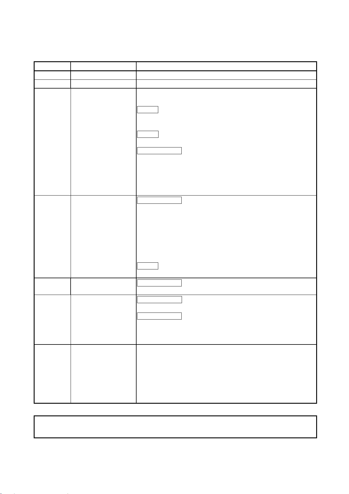
Always connect the master module and CC-Link dedicated cable at the data link terminal block.
If the data link terminal block and general-purpose input/output terminal block are incorrectly
inserted, module trouble could occur.
Data link terminal
bloc
General-purpose input/
output terminal block
[Mounting Instructions]
!
CAUTION
Use this module within the general specification environment described in the manual.
Use in an environment outside the general specification range could lead to electric shocks,
fires, malfunctioning, product damage or deterioration.
Always connect the crimp, press-fit or solder the connector wire connections with the maker-
designated tools, and securely connect the connector to the module.
An incomplete connection could lead to short-circuits or malfunctioning.
Do not directly touch the conductive section of the module.
Failure to observe this could lead to module malfunctioning or trouble.
Securely fix the module with the DIN rail or installation screw. Tighten the installation screw
within the designated torque range.
A loose screw could lead to dropping, short-circuiting or malfunctioning.
If the screw is too tight, dropping or short-circuiting could occur due to screw damage.
Securely mount the connector of each connection cable to the mounting section.
An incomplete connection could lead to malfunctioning caused by an incorrect contact.
A - 2
Page 5

[Wiring Instructions]
!
CAUTION
Before starting installation or wiring work, be sure to shut off all phases of external power supply
used by the system.
Failure to shut off all phases could lead to electric shocks, product damage or malfunctioning.
Always install the terminal covers enclosed with the product before turning ON the power or
operating the product after installation or wiring work.
Failure to install the terminal cover could lead to electric shocks.
Always ground the FG terminal with Class D grounding (Class 3 grounding) dedicated of the
programmable controller.
Failure to do so could lead to malfunctioning.
Always confirm the product's rated voltage and terminal layout before wiring the module.
Connecting with a power supply other than the rated power supply, or incorrect wiring could
lead to fires or trouble.
Tighten the terminal screws within the specified torque range.
A loose terminal screw could lead to short-circuiting or malfunctioning.
If the terminal screw is too tight, dropping or short-circuiting could occur due to screw damage.
Make sure that foreign matter, such as cutting chips or wire scraps, do not enter the module.
Failure to observe this could lead to fires, trouble or malfunctioning.
The communication cables and power supply cable connected to the module must be placed in
a conduit or fixed with a clamp.
If the cable is not placed in a conduit or fixed with a clamp, the module or cable could be
damaged by the cable variation, movement or unintentional pulling leading to malfunctioning
caused by an improper cable connection.
Do not install the control lines together with the communication cables, or bring them close to
each other. Failure to do so may cause malfunctions due to noise.
Do not remove the communication cable or power supply cable connected to the module by
pulling on the cable section.
If the cable has a connector, hold the connector at the section connected to the module, and
remove.
If the cable does not have a connector, loosen the screws at the section connected to the
module, and remove.
Pulling on the cable while connected to the module could lead to module or cable damage, or
malfunctioning caused by an improper cable connection.
A - 3
Page 6
[Startup/Maintenance Instructions]
!
CAUTION
When power is ON, do not touch the terminals.
Doing so can cause an electric shock or malfunction.
Before cleaning or tightening the terminal screws and module mounting screws, be sure to shut
off all phases of external power supply used by the system.
Failure to shut off all phases could lead to module trouble or malfunctioning.
Do not touch the connector inside the lid at the front of the module.
Failure to observe this could lead to module trouble or malfunctioning.
Never disassemble or modify the module.
Failure to observe this could lead to trouble, malfunctioning, injuries or fires.
Do not drop or apply any strong impact to the module. Doing so may damage the module.
Before installing or removing the module on the panel, be sure to shut off all phases of external
power supply used by the system.
Failure to shut off all phases could lead to module trouble or malfunctioning.
Do not install/remove the terminal block more than 50 times after the first use of the product.
(IEC 61131-2 compliant)
[Disposal Instructions]
!
CAUTION
When disposing of the product, handle it as industrial waste.
A - 4
Page 7
REVISIONS
*
The instruction manual No. is described on the lower left of the back cover of this instruction manual.
Date of print * Instruction manual No. Revision details
Jul., 1997 IB (NA)-66781-A Initial print
Apr., 1999 IB (NA)-66781-B Complete review
Sep., 2002 IB (NA)-66781-C Equivalent to Japanese version D
Addition of description for use of the QCPU (Q mode)
Addition
Compliance with the EMC/Low Voltage Directive, Section 4.5.1,
Section 5.2.2
Deletion
Section 2.3
Partial Correction
SAFETY INSTRUCTIONS, About Manuals, Chapter 1, Section 2.1,
Section 2.2, Section 3.1, Section 3.2, Section 3.3, Section 3.4, Section
3.7, Section 4.1, Section 4.2, Section 4.4, Section 4.5.2, Section 4.5.3,
Section 4.6, Section 5.2, Section 5.6.2, Section 8.3, Section 9.1,
Section 9.2.4, Section 10.1.2, Section 10.2
Nov., 2005 IB (NA)-66781-D
Partial Correction
SAFETY INSTRUCTIONS, About Manuals, Generic Terms and
Abbreviations, Definitions and Details of Terms, Section 1.1, Section
2.1, 2.2, Section 3.1, 3.2, 3.4, 3.6.1, 3.6.2, 3.7, 3.8, 3.9.1, 3.9.2,
Section 4.2, 4.4, 4.5.2, 4.5.3, Section 5.2.1, 5.3, 5.4, 5.5.1, 5.5.2,
5.7.1, 5.7.2, 5.7.3, 5.7.4, Section 6.3.1, 6.3.2, 6.4.1, 6.4.2, Section
7.3.1, 7.4.3, 7.5.2, Section 8.2, 8.3, 8.4, 8.5, 8.9.2, Section 9.1, 9.2.1,
9.2.2, 9.2.3, 9.2.4, 9.3.2, 9.3.3, Section 10.1.2, 10.3
Addition
INDEX
Oct., 2006 IB (NA)-66781-E
Partial Correction
SAFETY INSTRUCTIONS, Section 3.2, 3.4, 4.4, 7.3
Nov., 2007 IB (NA)-66781-F
Change of a term
"PLC" was changed to "programmable controller".
Partial Correction
Section 4.2, 4.4, Section 5.1, 5.2.1, 5.5.1, 5.6.2, 5.7.3, Section 6.2,
6.3, 6.4.1, 6.4.2, Section 7.4.3, Section 8.10, Section 9.2.1, 9.2.2,
9.2.4, 9.3.1, 9.3.3, Section 10.1.2, 10.3, 10.4
Japanese Manual Version SH-3633-G
This manual does not guarantee the implementation of industrial rights or other rights, and does not authorize the
implementation rights. Mitsubishi shall not be held liable for any problems regarding industrial rights that occur through
the use of the contents given in this manual.
© 1997 MITSUBISHI ELECTRIC CORPORATION
A - 5
Page 8

INTRODUCTION
Thank you for purchasing the Mitsubishi general-purpose programmable controller MELSEC-A.
Always read through this manual, and fully comprehend the functions and performance of the A Series
programmable controller before starting use to ensure correct usage of this product.
Make sure that this manual is delivered to the final user.
CONTENTS
Safety Instructions..........................................................................................................................................A- 1
Revisions ........................................................................................................................................................A- 5
About Manuals ...............................................................................................................................................A- 9
Compliance with the EMC/Low Voltage Directive.........................................................................................A- 9
Using This Manual.........................................................................................................................................A- 10
Generic Terms and Abbreviations ................................................................................................................A- 11
Definitions and Details of Terms...................................................................................................................A- 12
1. OUTLINE 1- 1 to 1- 4
1.1 Features ................................................................................................................................................... 1- 2
2. SYSTEM CONFIGURATION 2- 1 to 2- 2
2.1 System configuration ............................................................................................................................... 2- 1
2.2 Applicable systems .................................................................................................................................. 2- 2
3. SPECIFICATIONS 3- 1 to 3- 26
3.1 General specifications.............................................................................................................................. 3- 1
3.2 Performance specifications...................................................................................................................... 3- 2
3.3 RS-232-C interface specifications ...........................................................................................................3- 3
3.4 General-purpose input/output specifications........................................................................................... 3- 4
3.5 List of functions ........................................................................................................................................ 3- 6
3.6 Input/output signals for master module ................................................................................................... 3- 7
3.6.1 List of input/output signals................................................................................................................. 3- 7
3.6.2 Details of input/output signals ........................................................................................................... 3- 8
3.7 R2 buffer memory list .............................................................................................................................. 3- 13
3.8 Transmission delay time ......................................................................................................................... 3- 19
3.9 Transmission/reception time................................................................................................................... 3- 20
3.9.1 When using buffer memory automatic update function .................................................................. 3- 20
3.9.2 When using transmission/reception buffer ...................................................................................... 3- 23
4. PROCEDURES AND SETTINGS BEFORE OPERATIION 4- 1 to 4- 12
4.1 Procedures before operation ...................................................................................................................4- 1
4.2 Precautions for handling ..........................................................................................................................4- 3
4.3 Installation environment ........................................................................................................................... 4- 5
4.4 Names of each part, and settings............................................................................................................ 4- 6
4.5 Wiring........................................................................................................................................................ 4- 8
A - 6
Page 9

4.5.1 Precautions for handling the CC-Link dedicated cables .................................................................. 4- 8
4.5.2 Connection of the CC-Link dedicated cables ................................................................................... 4- 8
4.5.3 Connection with external device ....................................................................................................... 4- 9
4.6 Checking the module’s state (Hardware test) ........................................................................................ 4- 11
5. PRELIMINARY INFORMATION 5- 1 to 5- 46
5.1 System used in this manual ..................................................................................................................... 5- 1
5.2 Programming Precautions ....................................................................................................................... 5- 3
5.2.1 About bank changing of the A series master module ...................................................................... 5- 3
5.2.2 About dedicated commands for use of the buffer memory automatic update function .................. 5- 5
5.3 Program basic format............................................................................................................................... 5- 6
5.4 Initializing the master station.................................................................................................................... 5- 9
5.5 Initializing the R2 ..................................................................................................................................... 5- 12
5.5.1 Using the buffer memory automatic update function ......................................................................5- 12
5.5.2 Using the transmission/reception buffer ..........................................................................................5- 15
5.6 Reading and writing the buffer memory (using the buffer memory automatic update function) .......... 5- 18
5.6.1 Outline............................................................................................................................................... 5- 18
5.6.2 Understanding the roles of each area ............................................................................................. 5- 19
5.7 Reading and writing the buffer memory (using the transmission/reception buffer) ..............................5- 28
5.7.1 Outline............................................................................................................................................... 5- 28
5.7.2 About control data ............................................................................................................................5- 29
5.7.3 Reading the R2 buffer memory........................................................................................................ 5- 40
5.7.4 Writing to the R2 buffer memory...................................................................................................... 5- 43
6. EXCHANGING DATA WITH AN EXTERNAL DEVICE 6- 1 to 6- 30
6.1 Matters to understand before transmitting data ...................................................................................... 6- 1
6.2 Matters to know before receiving data .................................................................................................... 6- 5
6.3 Exchanging data using the buffer memory automatic update function .................................................. 6- 9
6.3.1 Transmitting data to an external device .......................................................................................... 6- 9
6.3.2 Receiving data from an external device .......................................................................................... 6- 14
6.4 Exchanging data using the transmission/reception buffer.....................................................................6- 18
6.4.1 Transmitting data to an external device ..........................................................................................6- 18
6.4.2 Receiving data from an external device .......................................................................................... 6- 24
7. USING FRAMES WHEN EXCHANGING DATA 7- 1 to 7- 38
7.1 What are frames?..................................................................................................................................... 7- 1
7.2 Transmitting data using frames ............................................................................................................... 7- 2
7.2.1 Transmitting using transmission frame 1 area .................................................................................7- 2
7.2.2 Transmitting using the transmission frame 2 area........................................................................... 7- 4
7.3 Receiving data using frames ................................................................................................................... 7- 6
7.3.1 Reception data ..................................................................................................................................7- 8
7.3.2 Reading the reception data.............................................................................................................. 7- 10
7.4 Transmitting data at the device and status change ............................................................................... 7- 13
7.4.1 Outline............................................................................................................................................... 7- 13
7.4.2 Devices and statuses that can be designated................................................................................. 7- 14
7.4.3 Setting the R2 buffer memory.......................................................................................................... 7- 15
A - 7
Page 10

7.4.4 Precautions....................................................................................................................................... 7- 21
7.5 Registration frames ................................................................................................................................. 7- 22
7.5.1 List of default registration frames..................................................................................................... 7- 23
7.5.2 Details of user registration frames ................................................................................................... 7- 25
8. OTHER FUNCTIONS 8- 1 to 8- 24
8.1 Canceling data communication to an external device ............................................................................ 8- 1
8.2 Forcibly completing reception .................................................................................................................. 8- 3
8.3 Flow control .............................................................................................................................................. 8- 6
8.4 ASCII-BIN conversion of transmission data ........................................................................................... 8- 10
8.5 RW update function ................................................................................................................................ 8- 12
8.6 Initializing the R2 ..................................................................................................................................... 8- 15
8.7 Clearing the OS reception area ..............................................................................................................8- 16
8.8 Registering and initializing the R2 EEPROM ......................................................................................... 8- 19
8.9 Controlling the RS-232-C signal ............................................................................................................. 8- 22
8.9.1 Correspondence of RS-232-C control signal and remote input/output signal ............................... 8- 22
8.9.2 Precautions for using RS-232-C control signal read/write function ................................................ 8- 23
8.10 Confirming the R2 switch states and software version........................................................................ 8- 24
9. PROGRAM EXAMPLES 9- 1 to 9- 48
9.1 Conditions for program examples ........................................................................................................... 9- 1
9.2 Example of program for using buffer memory automatic update function ............................................. 9- 2
9.2.1 When using FROM/TO command with ACPU / QCPU-A (A mode) ...............................................9- 2
9.2.2 When using dedicated commands with ACPU / QCPU-A (A mode) .............................................. 9- 6
9.2.3 When using dedicated commands with QCPU (Q mode) / QnACPU............................................ 9- 11
9.2.4 When using the FROM/TO commands with ACPU / QCPU-A (A mode)
(Three R2 modules connected) ......................................................................................................9- 14
9.3 Example of program for using transmission/reception buffer ................................................................ 9- 28
9.3.1 When using FROM/TO command with ACPU / QCPU-A (A mode) ..............................................9- 28
9.3.2 When using dedicated commands with ACPU / QCPU-A (A mode) ............................................. 9- 37
9.3.3 When using dedicated commands with QCPU (Q mode) / QnACPU............................................ 9- 43
10. TROUBLESHOOTING 10- 1 to 10- 12
10.1 Error codes ........................................................................................................................................... 10- 1
10.1.1 Error code storage area ................................................................................................................10- 1
10.1.2 List of error codes.......................................................................................................................... 10- 2
10.2 Confirming the error with the LED ....................................................................................................... 10- 5
10.3 Examples of trouble in general-purpose input circuit.......................................................................... 10- 7
10.4 Troubleshooting per symptom............................................................................................................. 10- 9
10.5 Troubleshooting when the master station's ERR. LED flashes......................................................... 10- 10
APPENDIX Appendix- 1 to Appendix- 2
Appendix 1 Outline dimension drawing ............................................................................................Appendix- 1
INDEX INDEX- 1 to INDEX 3
A - 8
Page 11

About Manuals
Related Manuals
The following manuals are also related to this product.
In necessary, order them by quoting the details in the tables below.
Manual Name
Control & Communication Link System Master/Local Module Type AJ61BT11/A1SJ61BT11
User's Manual
Explains the configuration, performance and specifications, functions, handling, wiring and
troubleshooting of the AJ61BT11 and A1SJ61BT11 system.
Control & Communication Link System Master/Local Module Type
AJ61QBT11/A1SJ61QBT11 User's Manual
Explains the configuration, performance and specifications, functions, handling, wiring and
troubleshooting of the AJ61QBT11 and A1SJ61QBT11 system.
CC-Link System Master/Local Module User's Manual QJ61BT11N
Explains the configuration, performance and specifications, functions, handling, wiring and
troubleshooting of the QJ61BT11N system. (Sold separately)
AnSHCPU/AnACPU/AnUCPU/QCPU-A (A mode) Programming Manual QJ61BT11
(Dedicated Instructions)
Explains the configuration, performance and specifications, functions, handling, wiring and
troubleshooting of the QJ61BT11 system. (Sold separately)
(Sold separately)
(Sold separately)
Compliance with the EMC/Low Voltage Directive
Manual Number
(Model Code)
IB-66721
(13J872)
IB-66722
(13J873)
SH-080394E
(13JR64)
IB-66251
(13J742)
When incorporating the Mitsubishi programmable controller into other machinery or
equipment and keeping compliance with the EMC and low voltage directives, refer to
Chapter 3, "EMC Directives and Low Voltage Directives" of the User's Manual
(Hardware) included with the CPU module or base unit used.
The CE logo is printed on the rating plate of the programmable controller, indicating
compliance with the EMC and low voltage directives.
To conform this product to the EMC Directive and Low Voltage Directive, refer to the
Section of "CC-Link Modules" in Chapter 3 "EMC Directive and Low Voltage Directive"
in the User’s Manual (Hardware) of the CPU module used or the programmable
controller CPU supplied with the base unit.
A - 9
Page 12

Using This Manual
This section "Using this manual" describes the R2 usage in categories of purpose.
Refer to the following details when using this manual.
(1) To find the characteristics of R2 (Section 1.1)
The features are described in section 1.1.
(2) To find the system configuration (Section 2.1)
The configuration of a system using R2 is explained in section 2.1.
(3) To find the master module that can use R2, and the CPU version that can use the
CC-Link dedicated commands (Section 2.2)
The master module that can use R2, and the CPU version that can use the CCLink dedicated commands are explained in section 2.2.
(4) To find the R2 specifications (Chapter 3)
The R2 specifications are described in Chapter 3.
(5) To find the time for transmitting/receiving data with R2 (Sections 3.8, 3.9)
The R2 transmission delay time and transmission/reception time are explained in
sections 3.8 and 3.9.
(6) To find the procedures for operating R2 (Chapter 4)
The procedures for operating the R2, and the methods of checking the module
state are explained in Chapter 4.
(7) To find how to access the R2 buffer memory (Sections 5.6, 5.7)
The methods of accessing the buffer memory are described in sections 5.6 and
5.7.
(8) To exchange data with an external device (Chapter 6)
The methods of exchanging data with an external device are explained in Chapter
6.
(9) To add a frame when exchanging data (Chapter 7)
The details of the frame, and the methods of adding a frame are explained in
Chapter 7.
(10) To find sample programs (Chapter 9)
Sample programs are described in Chapter 9.
(11) When trouble occurs (Chapter 10)
The error code list and troubleshooting are described in Chapter 10.
"How to Use This Manual" is described by purposes of using CSKP.
Refer to the following and use this manual.
A - 10
Page 13

Generic Terms and Abbreviations
Unless specially noted, the following generic terms and abbreviations are used in this
manual to explain the AJ65BT-R2 type RS-232-C interface module.
Generic term/abbreviation Details of generic term/abbreviation
R2 Abbreviation for AJ65BT-R2 type RS-232-C interface module.
CC-Link Abbreviation for Control & Communication Link system.
Master module Generic term when using AJ61QBT11, A1SJ61QBT11, AJ61BT11, A1SJ61BT11, QJ61BT11
and QJ61BT11N as the master station.
Remote module Generic term for AJ65BTB - , AJ65BTC - , AJ65BT-64AD, AJ65BT-64DAV and
AJ65BT-64DAI.
External device Generic term for devices such as ID controller, bar code reader and general-purpose personal
computer, connected to R2 for data communication.
GPPW Generic term for model names: SWnD5C-GPPW, SWnD5C-GPPW-A, SWnD5C-GPPW-V
and SWnD5C-GPPW-VA. (“n” included in the model name indicates a number “4” or more.)
AnNCPU Abbreviation of A0J2HCPU, A1SCPU, A1SCPUC24-R2, A1SHCPU, A1SJCPU, A1SJCPU-
S3, ASJHCPU, A1NCPU, A2CCPU, A2CCPUC24, A2CCPUC24-PRF, A2CJCPU, A2NCPU,
A2NCPU-S1, A2SCPU, A2SHCPU and A2FXCPU
AnACPU Abbreviation of A2ACPU, A2ACPU-S1, A2ACPUP21/R21, A2ACPUP21/R21-S1,
A3ACPUP21/R21, A3NCPU and A3ACPU
AnUCPU Abbreviation of A2UCPU, A2UCPU-S1, A2USCPU, A2USCPU-S1, A2USHCPU-S1, A3UCPU
and A4UCPU
QnACPU Abbreviation of Q2ACPU, Q2ACPU-S1, Q2ASCPU, Q2ASCPU-S1, Q2ASHCPU,
Q2ASHCPU-S1, Q3ACPU, Q4ACPU and Q4ARCPU
ACPU Abbreviation of AnNCPU, AnACPU and AnUCPU
QCPU (Q mode) Generic term for Q02CPU, Q02HCPU, Q06HCPU, Q12HCPU and Q25HCPU
QCPU-A (A mode) Generic term for Q02CPU-A, Q02HCPU-A and Q06HCPU-A
A - 11
Page 14

Definitions and Details of Terms
The definitions and details of terms used in this manual are explained below.
(1)
M
H
This indicates the buffer memory address of the master station.
(2)
R2
H
This indicates the buffer memory address of R2.
(3) Master station
The station that controls the remote station, local station and intelligent device
station.
(4) Intelligent device station
Slave station on CC-Link system that can carry out transient transmission with R2,
etc.
(5) Transient transmission
Function that communicates data with a designated station when access is
requested from the programmable controller CPU, etc.
(6) Buffer memory automatic update function
Function that automatically updates the data between the R2 buffer memory and
master stations' automatic update buffer.
(7) Automatic update buffer
Buffer memory in master station used for the buffer memory automatic update
function in respect to R2.
(8) Registration frame
Row of data targeted for the fixed format section of the statement transmitted and
received between the external device and R2.
The registration frames include the default registration frame registered in the R2,
and the user registration frame registered by the user using EEPROM.
(9) Transmission frame 1 area
Buffer memory address
R2
118H to 119H.
With frame transmission that uses the transmission frame 1 area, a frame can be
added each to the head and end of a random data item when transmitting the
data.
(10) Transmission frame 2 area
Buffer memory address
R2
120H to 185H.
With frame transmission that uses the transmission frame 2 area, up to 100
frames can be added when transmitting the data.
A - 12
Page 15
A
1 OUTLINE
1. OUTLINE
MELSEC-
1
This User's Manual explains the features and specifications of the R2 used as the
intelligent device station of the CC-Link, communication with an external device, and
the special specifications, etc.
R2 can exchange data with an external device, such as an RS-232-C connection type
barcode reader, ID controller or general-purpose personal computer.
When a barcode reader is connected
Programmable controller
Master station
R2
Data reception
Barcode reader
Reading!
1 - 1
Page 16
A
1 OUTLINE
1.1 Features
MELSEC-
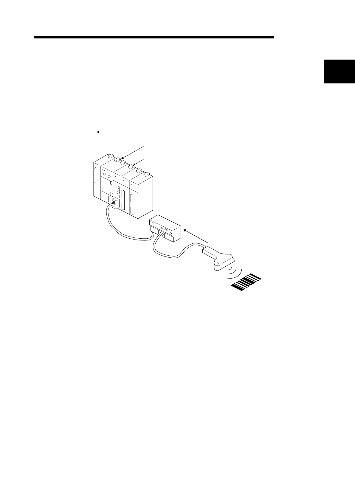
(1) Easy communication by using the buffer memory automatic update
function.
This function automatically updates the buffer memory between the R2 and
master station at the timing set in R2.
With this, a program to read and write between the R2 and master station can be
eliminated. As the data can be read and written with just the FROM/TO
command, the program is simplified.
(This can be used with all CPUs.)
Carried out with sequence program
Programable controller CPU
1)
TO
FROM
4)
Master station
Buffer memory
(Automatic
update
1
buffer )
*
R2
2)
Buffer
memory
3)
*1 The address differs as shown below
for the A Series and Q/QnA Series.
A Series : Bank 2 M 0
Q/QnA Series : M 2000H to 2FFF
Automatically updated
to FFF
H
H
H
1) The data to be stored in the R2 buffer memory is written into the master
station's automatic update buffer.
2) The data is automatically written in at the R2 timing.
3) The data is automatically read at the R2 timing.
4) The corresponding master station's buffer memory is read to the data in the
R2 buffer memory to be read out.
1 - 2
Page 17
A
1 OUTLINE
MELSEC-
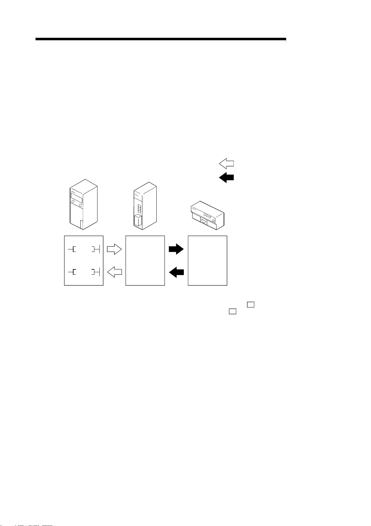
(2) Addition of frame during data transmission/reception with external
device
By adding a frame to the head and end, a statement format matching the
specifications of the external device, such as the barcode reader or ID controller,
can be created and communicated.
The frames include those that are set as the default, and the frames that can be
randomly created by the user (user registration frame).
A random frame can be added!
Random data
Data transmission
R2
Master station
Monitors the status
of RX, RY and RW,
etc.
Random data
Data reception
External device such as barcode reader,
ID controller, general-purpose personal computer
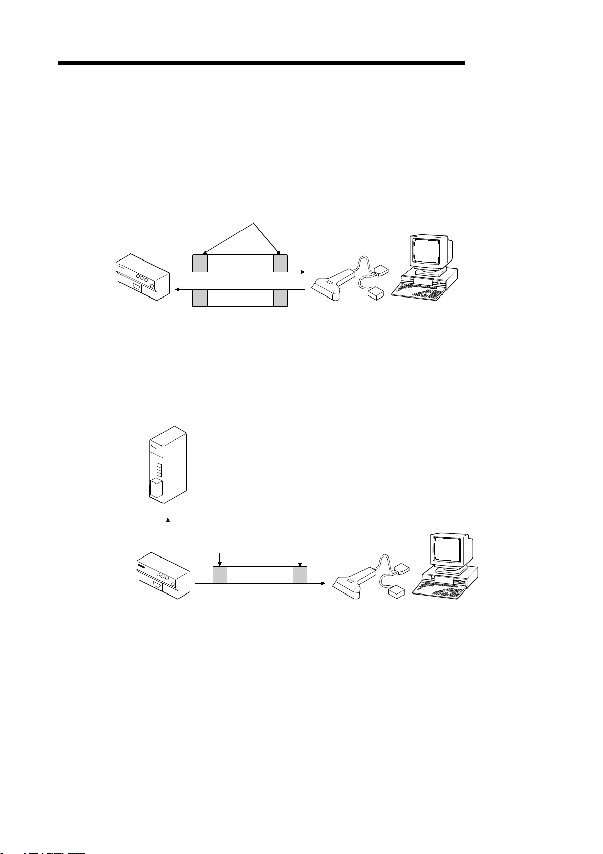
(3) Automatic transmission possible when user-set transmission
conditions are established
When the user-designated transmission conditions (changes in RX, RY, RW,
etc.), are established, data can be automatically transmitted to the external
device.
Head frame
External device such as barcode reader,
ID controller, general-purpose personal computer
R2
Final frame
Random data
Transmit data after conditions
are established!
(4) Two general-purpose input/output points each provided as a
standard
Two points each are provided for the general-purpose input and output so the
synchronous signal with the barcode reader and ID controller, etc., can be
directly input and output without providing a separate remote I/O module.
1 - 3
Page 18

A
1 OUTLINE
MEMO
MELSEC-
1 - 4
Page 19
A
2 SYSTEM CONFIGURATION
2. SYSTEM CONFIGURATION
The system configuration for using R2 is shown explained in this section.
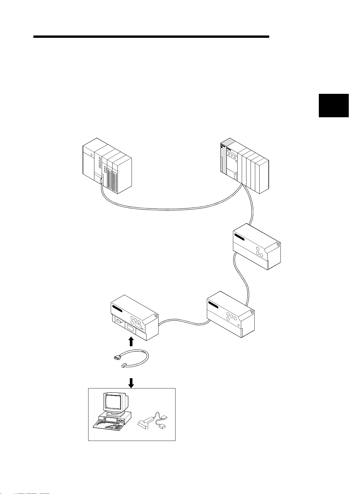
2.1 System configuration
The system configuration for using R2 is shown below.
Up to 26 R2 modules can be connected to one master station.
CC-Link master/local station (master station) CC-Link master/local station (local station)
MELSEC-
2
CC-Link dedicated cable
AJ65BT-R2
(Intelligent device station)
RS-232-C cable
Remote I/O station
Remote device station
1-station occupation
RX/RY 32 points each
RWr/RWw 4 points each
Personal computer Bar code reader
External device
2 - 1
Page 20
A
2 SYSTEM CONFIGURATION
2.2 Applicable systems
The master module of the CC-Link system that can use R2, and the programmable
controller CPU that can use the CC-Link dedicated commands are explained in this
section.
(1) Applicable master modules
The following indicates the master modules that can use the R2.
AJ61BT11
A1SJ61BT11
AJ61QBT11
A1SJ61QBT11
QJ61BT11N
QJ61BT11
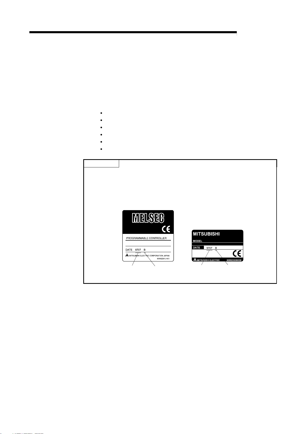
POINT
When using any of the AJ61BT11, A1SJ61BT11, AJ61QBT11 and A1SJ61QBT11,
use the one that has the following number (9707 B or later) in the DATE field of the
rating plate.
The module that does not have "9707 B" in the DATE field cannot use the R2.
MELSEC-
<Large type>
<Compact type>
Date of Function version Date of Function version
manufacture manufacture
(2) Restrictions on use of CC-Link dedicated commands
Depending on the used programmable controller CPU and master module, the
CC-Link dedicated commands may be unusable.
For details of the restrictions, refer to the A Series Master Module User's Manual
(Details) and AnSHCPU/AnACPU/AnUCPU Programming Manual (Dedicated
Instructions).
For program examples using the dedicated commands, refer to Section 9.2.2,
Section 9.2.3, Section 9.3.2 and Section 9.3.3.
2 - 2
Page 21
A
3 SPECIFICATIONS
3. SPECIFICATIONS
3.1 General specifications
The general specifications of the R2 are shown below.
Item Specifications
Working ambient
temperature
Storage ambient
temperature
Working ambient humidity 10 to 90%RH, with no dew condensation
Storage ambient humidity 10 to 90%RH, with no dew condensation
Frequency Acceleration Amplitude No. of sweeps
10 to 57Hz – 0.075mmWhen there is
JIS B 3502,
Vibration resistance
Impact resistance
Working atmosphere No corrosive gases
Working altitude *
Installation place Inside control panel
Overvoltage category *
Degree of contamination
2
*
3
IEC 61131-2
compliant
JIS B 3502, IEC 61131-2 compliant (147m/s
1
intermittent
vibration
When there is
continuous
vibration
57 to 150Hz
10 to 57Hz – 0.035mm
57 to 150Hz
-20 to 75°C
2000m or less
0 to 55
II or less
2 or less
°
C
2
9.8m/s
2
4.9m/s
2
, 3 times each in X, Y and Z directions)
–
–
MELSEC-
3
10 times each in
X, Y and Z
directions
(for 80 minutes)
*1 Indicates to which power distribution section, from the public power distribution network to the in-plant
machine device, the device is assumed to be connected.
Category II applies to a device fed power from a fixed facility.
The withstand surge voltage level for a device with a rating up to 300V is 2500V.
*2 Exponential indicating the degree of conductive matter generated in the environment where device is
used.
In the degree of contamination level 2, only non-conductive contaminants are generated. However,
temporary conductivity could occur due to rare condensation.
*3 Do not use or store the programmable controller in the environment where the pressure is higher than the
atmospheric pressure at sea level. Otherwise, malfunction may result. To use the programmable controller
in high-pressure environment, contact your nearest Mitsubishi representative.
3 - 1
Page 22
A
3 SPECIFICATIONS
×
×
⋅
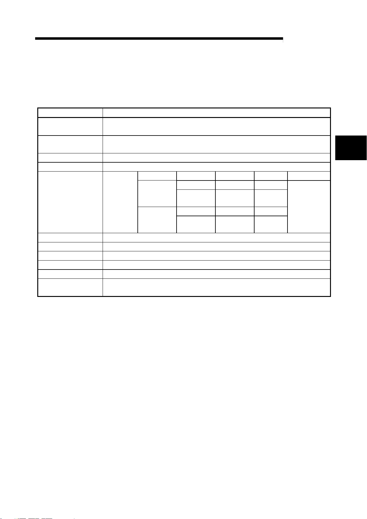
3.2 Performance specifications
The R2 performance specifications are shown below.
(1) RS-232-C specifications
Item Specifications
Interface specifications RS-232-C compliant, 1 channel (Refer to section 3.3)
Transmission method Full duplex communication method
Synchronization method Start-stop synchronization method
Transmission speed 300, 600, 1200, 2400, 4800, 9600, 19200bps
(Select with RS-232-C transmission specification setting switch)
Data format
Error detection With parity check (even/odd)/None
(flow control)
Transmission distance 15m
OS reception area 5120 bytes
Star bit 1
Data bit 7/8
Parity bit 1 (Yes)/0 (No)
Stop bit 1/2
DTR/DSR (ER/DR) controlCommunication control
DC1/DC3 control
MELSEC-
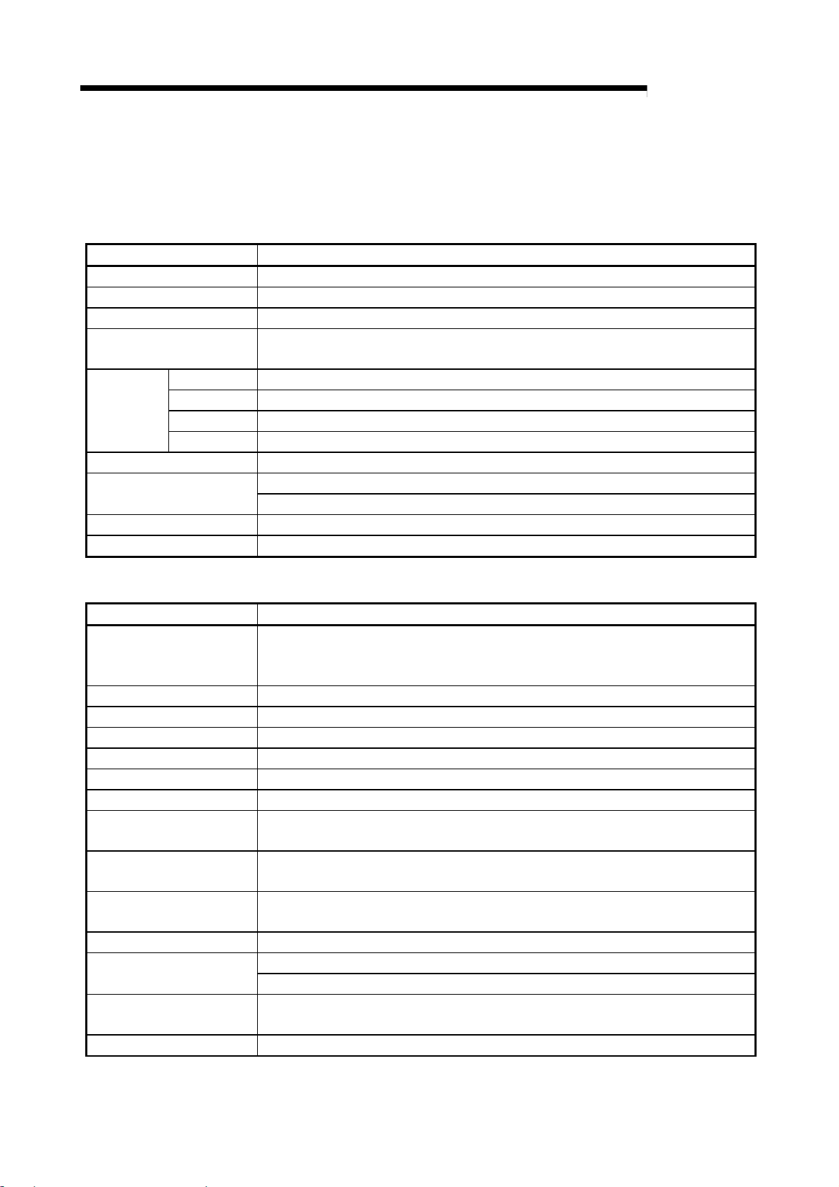
(2) Data link specifications
Item Specifications
General-purpose input/output
specifications
Transmission path Bus (RS-485)
EEPROM writing life 100,000 times
CC-Link station type Intelligent device station
No. of occupied stations 1 station (RX/RY 32 points each, RWw/RWr 4 points each)
Connection cable CC-Link dedicated cable
Withstand voltage One minute at 500VAC between DC external terminal batch and grounding
Insulation resistance
Noise withstand level DC type noise voltage 500Vp-p
Module installation screw
Applicable DIN rail TH35-7.5Fe, TH35-7.5Al, TH35-15Fe (JIS C 2812 compliant)
External power supply
Tolerable instantaneous
power failure time
Weight 0.40kg
Input side : 24VDC (Positive common/negative common shared type) 2 points
Output side : Transistor output (sink type) 12/24VDC 2 points Terminal block (Refer to
section 3.4)
Ω
or more with 500VDC insulation resistance meter between DC external terminal
10M
batch and grounding
μ
With noise width 1
(Tightening torque range 0.78 to 1.18N
s, noise frequency 25 to 60Hz noise simulator
0.7mm
M4
Current consumption: 0.11A
16mm or more screw
24VDC
1ms
m)
3 - 2
Page 23
A
3 SPECIFICATIONS
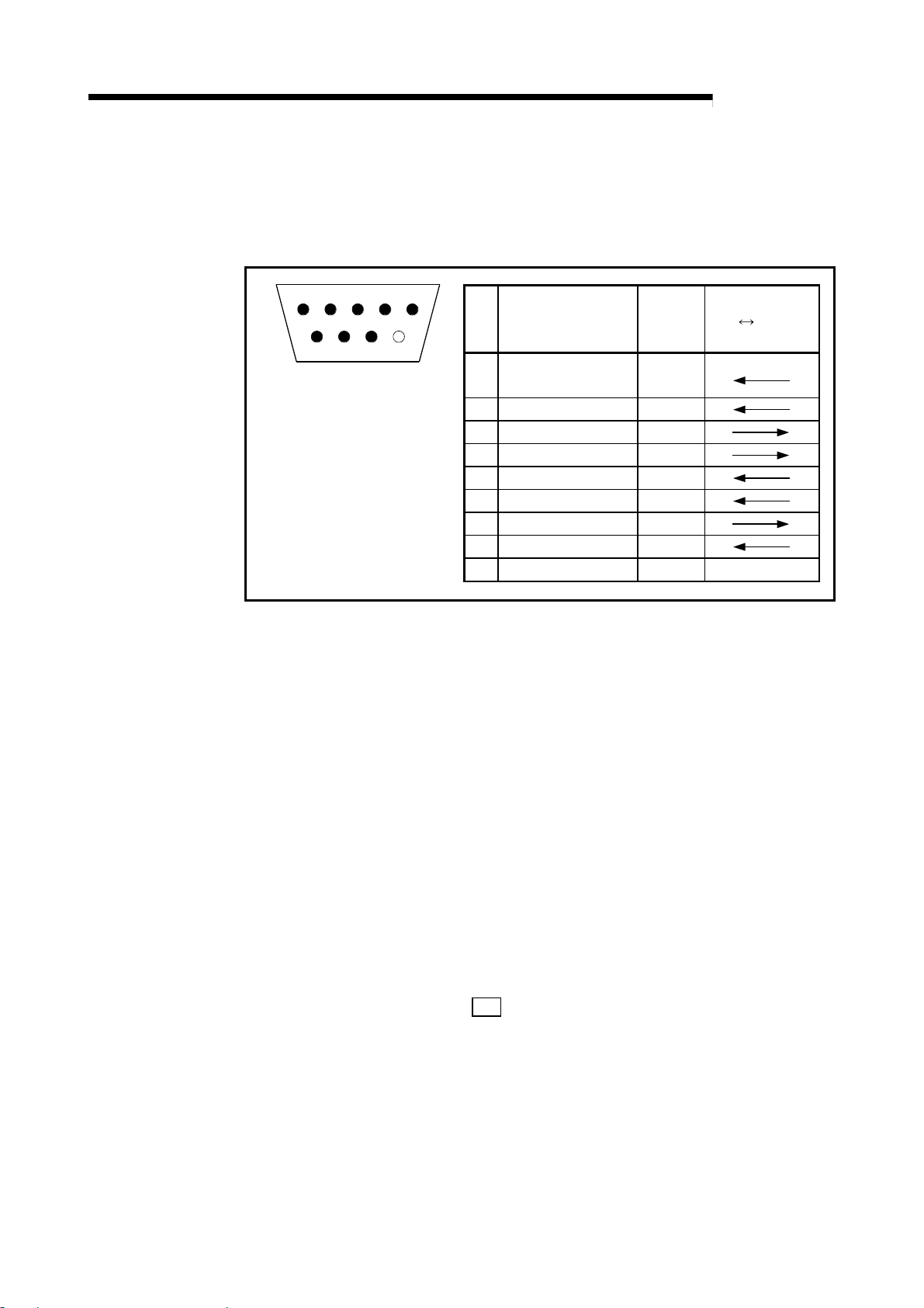
3.3 RS-232-C interface specifications
The specifications of the RS-232-C interface for connection with an external device are
shown below.
MELSEC-
1 2 3 4 5
6
7 8 9
The following type of connector
is mounted on the R2 side, so
use a mate connector that
matches this type.
9-pin D-SUB (female) screw-
fixed type
DDK Ltd.
17L-10090-27-D9AC
Pin
No.
Reception carrier
1
detection
2 Reception data RD(RXD)
3 Transmission data SD(TXD)
4 Data terminal ready ER(DTR)
5 Signal ground SG
6 Data set ready DR(DSR)
7 Transmission request RS(RTS)
8 Transmission enable CS(CTS)
9 Not used – –
Name
Signal
abbrev.
CD
Signal direction
external
R2
device
The details of each signal are explained below.
CD.................. The CD signal status can be read with the input signal RXnB.
ER (DTR) ....... When using DTR/DSR control, this is turned ON and OFF according
to the empty size of the OS reception area for storing the received
data.
(The DTR signal turns ON when the RS can receive data.)
When not using DTR/DSR control, the output signal RYnA is followed.
DR (DSR) ...... When using DTR/DSR control, if this is OFF, data will not be
transmitted from R2 to the external device.
Set this to be always ON when the external device is in the reception
enabled state.
When not using DTR/DSR control, the DSR signal status will be
ignored.
RS .................. This follows the
R2 101H setting and output signal RYn9.
CS .................. When the CS signal is OFF, data will not be transmitted from R2 to
the external device.
Set this to be always ON when the external device is in the reception
enabled state.
A standard connection example of the RS-232-C cable is given in section 4.5.2.
3 - 3
Page 24
A
3 SPECIFICATIONS
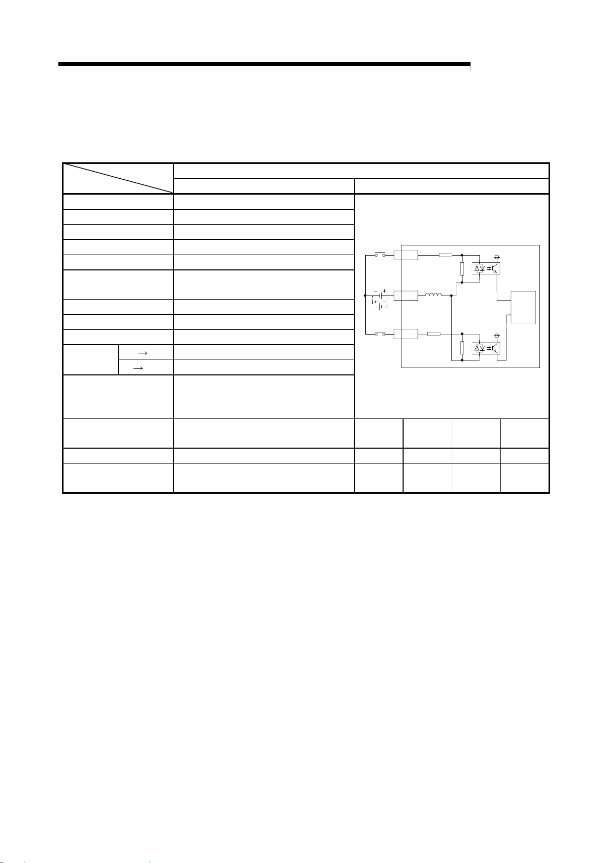
3.4 General-purpose input/output specifications
The general-purpose input/output specifications of the R2 are shown below.
(1) General-purpose input specifications
DC input (Positive common/negative common shared type)
R2 External connection view
No. of input points 2 points
Insulation method Photo coupler insulation
Rated input voltage 24VDC
Rated input current Approx. 7mA
Working voltage range 19.2 to 28.8VDC (ripple rate within 5%)
Max. No. of simultaneous
input points
ON voltage/ON current 14V or more/3.5mA or more
OFF voltage/OFF current 6V or less/1.7mA or less
Input resistance
Response
time
Common method
External connection
method
Applicable wire size
Applicable crimp terminal
OFF ON 10ms or less
ON OFF 10ms or less
100%
Approx. 3.3k
2 points/common (COM1)
Positive common/negative common shared
type
7-point terminal block (M3.5 screw)
0.75 to 2mm
RAV1.25-3.5, RAV2-3.5 (JIS C 2805
compliant)
Ω
2
MELSEC-
1XC
24VDC
COM1
2
3XD
Terminal
No.
TB1 XC TB3 XD
TB2 COM1 TB4 NC
Signal
name
Terminal
No.
Internal
Signal
name
circuit
3 - 4
Page 25
A
3 SPECIFICATIONS
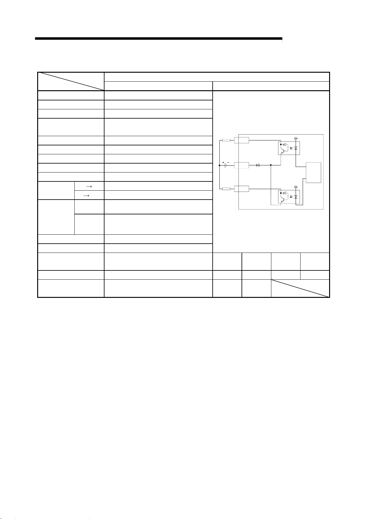
(2) General-purpose output specifications
R2 External connection view
No. of output points 2 points
Insulation method Photo coupler insulation
Rated load voltage 12/24VDC
Working load voltage
range
Max. load current 0.1A/point 0.2A/common
Max. rush current 0.4A 10ms or less
Leakage current at OFF 0.1mA or less
Max. voltage drop at ON 1.5VDC or less (MAX) 0.1A
Output type Sink type
Response
time
Output section
OFF ON 2ms or less
ON OFF 2ms or less (resistance load)
Voltage 10.2 to 28.8VDC (ripple rate within 5%)
externally
supplied
Current
power
Surge killer Zener diode
Common method 2 points/common (COM2)
External connection
method
Applicable wire size
Applicable crimp terminal
10.2 to 28.8VDC (ripple rate within 5%)
50mA or less (TYP. 24VDC, per common)
Not including external load current.
7-point terminal block (M3.5 screw)
0.75 to 2mm
2
RAV1.25-3.5, RAV2-3.5 (JIS C 2805
compliant)
Transistor output (sink type)
L
5YC
12/24VDC
COM2
6
L
7YD
Terminal
No.
TB5 YC TB7 YD
TB6 COM2
Signal
name
MELSEC-
Terminal
No.
Internal
Signal
name
circuit
3 - 5
Page 26
A
3 SPECIFICATIONS
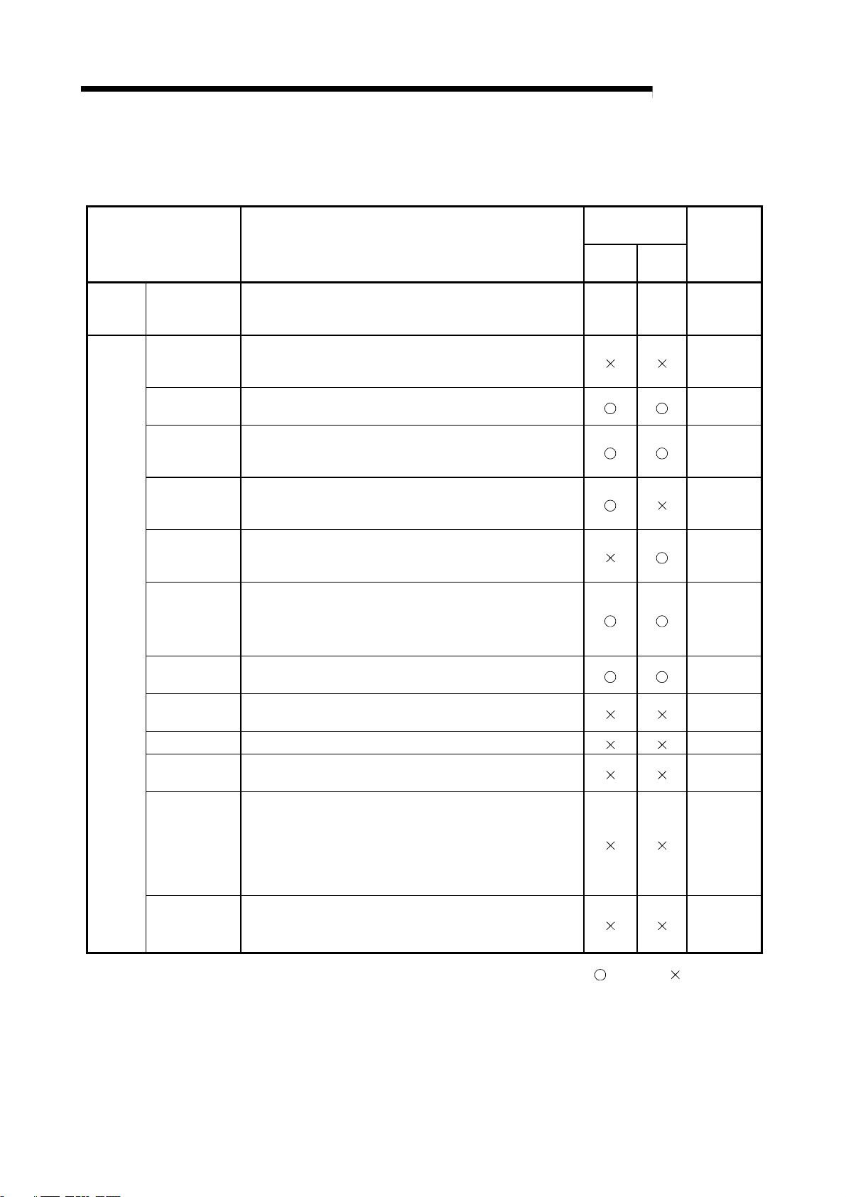
3.5 List of functions
Function Explanation
Main
function
Auxiliary
functions
Non-procedural
communication
function
Buffer memory
automatic
update
Frame addition
Monitor
transmission
Transmission
cancellation
Forced
reception
complete
Flow control
ASCII-BIN
conversion
RW update
R2 initialization Initializes the R2. Section 8.6
OS reception
area clear
Registration to
RS EEPROM
The R2 functions are shown below.
Non-procedural data transmission/reception with external
device such as barcode reader, ID controller, generalpurpose personal computer.
Automatically updates the buffer memory between the R2
and master station at the update timing set in each area of
the R2 buffer memory.
Adds a frame registered for R2 at the head and end of the
transmission data when transmitting data.
Automatically transmits data to the external device when the
user-designated transmission conditions (changes in RX, RY,
RW and status) are established.
After transmission request is issued from the master station
to R2, forcibly cancels the transmission before R2 completes
transmission to external device.
Forcibly completes the reception when reception data from
external device has not reached the reception complete data
size, etc., and reads out the currently received data.
Stops/resumes transmission of data from external device
according to open space in R2 OS reception area.
Stops/resumes transmission of data from R2 according to
requests from external device.
Carries out ASCII-BIN conversion on the
transmitted/received data.
Assigns master station remote register (RW) and R2 side
area to be automatically updated in the buffer memory.
Clears the received data stored in the R2 OS reception area.
Registers a setting value for the R2 buffer memory's specific
application area in the EEPROM, or returns the value
registered in the EEPROM to the R2 default value.
The value for the R2 buffer memory registered in the
EEPROM (including the setting values changed by the user)
is used as an initial value at the time of the R2 startup.
MELSEC-
Relation with
main function
Trans-
mission
Recep-
tion
– – Chapter 6
Reference
Section 5.6
Chapter 7
Section 7.4
Section 8.1
Section 8.2
Section 8.3
Section 8.4
Section 8.5
Section 8.7
Section 8.8
RS-232-C
signal control
Reads the status of the RS-232-C interface signal
stored in the R2 buffer memory, and controls the
output.
Section 8.9
: Related, : Not related
3 - 6
Page 27
A
3 SPECIFICATIONS
MELSEC-
3.6 Input/output signals for master module
The input/output signals (RX/RY) for the R2 master module are explained in this
section.
3.6.1 List of input/output signals
A list of the R2 input/output signals is shown below.
Signal direction Master module R2 Signal direction Master module R2
Device No. (input) Signal name Device No. (output) Signal name
RXn0 Transmission normal complete RYn0 Transmission request
RXn1 Transmission error complete RYn1 Transmission cancel request
RXn2 Reception normal read request RYn2 Reception read complete
RXn3 Reception error read request RYn3 Forced reception complete request
RXn4 Initialization normal complete RYn4 Initialization request
RXn5 Initialization error complete RYn5 Use prohibited
RXn6 OS reception area clear complete RYn6 OS reception area clear request
RXn7 EEPROM function normal complete RYn7 EEPROM function request
RXn8 EEPROM function error complete RYn8 Use prohibited
RXn9 CS (CTS) signal RYn9
RXnA DR (DSR) signal RYnA
RXnB
RXnC to RXnD General-purpose external input signal RYnC to RYnD General-purpose external output signal
RXnE to RX(n+1)8 Use prohibited RYnE to RY(n+1)8 Use prohibited
RX(n+1)9 Initial data read complete RY(n+1)9 Initial data read request
RX(n+1)A Error state RY(n+1)A Error reset request
RX(n+1)B Remote station ready
RX(n+1)C to
RX(n+1)D
RX(n+1)E Intelligent device station access complete RY(n+1)E Intelligent device station access request
RX(n+1)F Use prohibited RY(n+1)F Use prohibited
Signal status
Use prohibited
CD signal RYnB Use prohibited
RY(n+1)B to RY(n+1)D Use prohibited
Signal setting
n: Address assigned to master module with station No. setting.
RS (RST) signal *
ER (DTR) signal *
1
2
*1 The RS signal setting is valid when the "RS signal status designation (
RYn9 ON/OFF (1)". (Refer to section 8.9.)
*2 The ER signal setting is invalid when the "Flow control designation (
flow control. (DTR/DSR/ (ER/DR) control) (1)".
Important
Do not designate the RXn0 to RXn8, RXnE to RX(n+1)F, RYn0 to RYn9, RYnB, or RYnE to
RY (N+1)F signals to the following functions.
Monitor target RX/RY for monitor transmission function
Reference RX/RY for registration frame RX/RY/RW reference special character.
Do not output (turn ON) the usage-prohibited signals.
If an output is carried out to a usage-prohibited signal, the programmable controller system
could malfunction.
3 - 7
R2 101H)" is set to "Follow
R2 100H)" is set to "Carry out
Page 28
A
3 SPECIFICATIONS
t
t
3.6.2 Details of input/output signals
A detailed explanation of the R2 input/output signals is given below.
The lines in the timing chart indicate the following details.
(1) Remote input (RX)
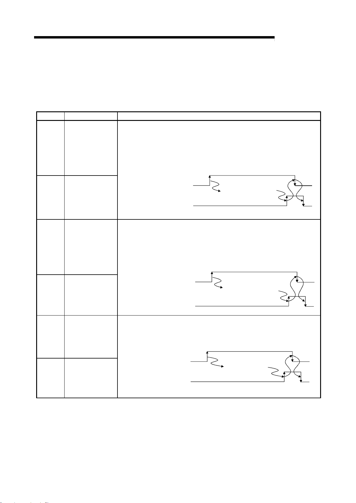
Device No. Signal name Details
When transmitting data to an external device connected to R2, after the transmission
data is written into the R2 transmission area, the transmission request (RYn0) is
turned ON.
RXn0
Transmission normal
complete
When the transmission is completed normally, transmission normal complete (RXn0)
turns ON, and if the transmission is completed abnormally, transmission error
complete (RXn1) turns ON.
The transmission request (RYn0) turns OFF when these signals turn ON.
MELSEC-
RXn1
RXn2
RXn3
RXn4
Transmission error
complete
Reception normal
read request
Reception error read
request
Initialization normal
complete
Transmission request (RYn0)
Transmission normal complete
(RXn0)
or Transmission error complete
(RXn1)
R2 transmits contents
of transmission area to
external device.
When data is received from an external device connected to R2 and the transmission
is completed normally, reception normal read request (RXn2) turns ON. If the
transmission is completed abnormally, reception error read request (RXn3) turns ON.
The reception data is stored in the R2 reception area at this time.
The data in the R2 reception area is read out when these signals turn ON, and read
complete (RYn2) turns OFF when the reading is completed.
Reception normal read reques
(RXn2)
or Reception error read reques
(RXn3)
Reception read complete (RYn2)
Reception area is read
with sequence program.
The initialization request (RYn4) is turned ON to initialize R2.
When the R2 is correctly initialized, initialization correct complete (RXn4) turns ON,
and when the process ends abnormally, initialization error complete (RXn5) turns ON.
The initialization request signal (RYn4) turns OFF when these signals turn ON.
RXn5
Initialization error
complete
Initialization request (RYn4)
Initialization normal complete
(RXn4)
or Initialization error complete
(RXn5)
3 - 8
R2 is initialized.
Page 29
A
3 SPECIFICATIONS
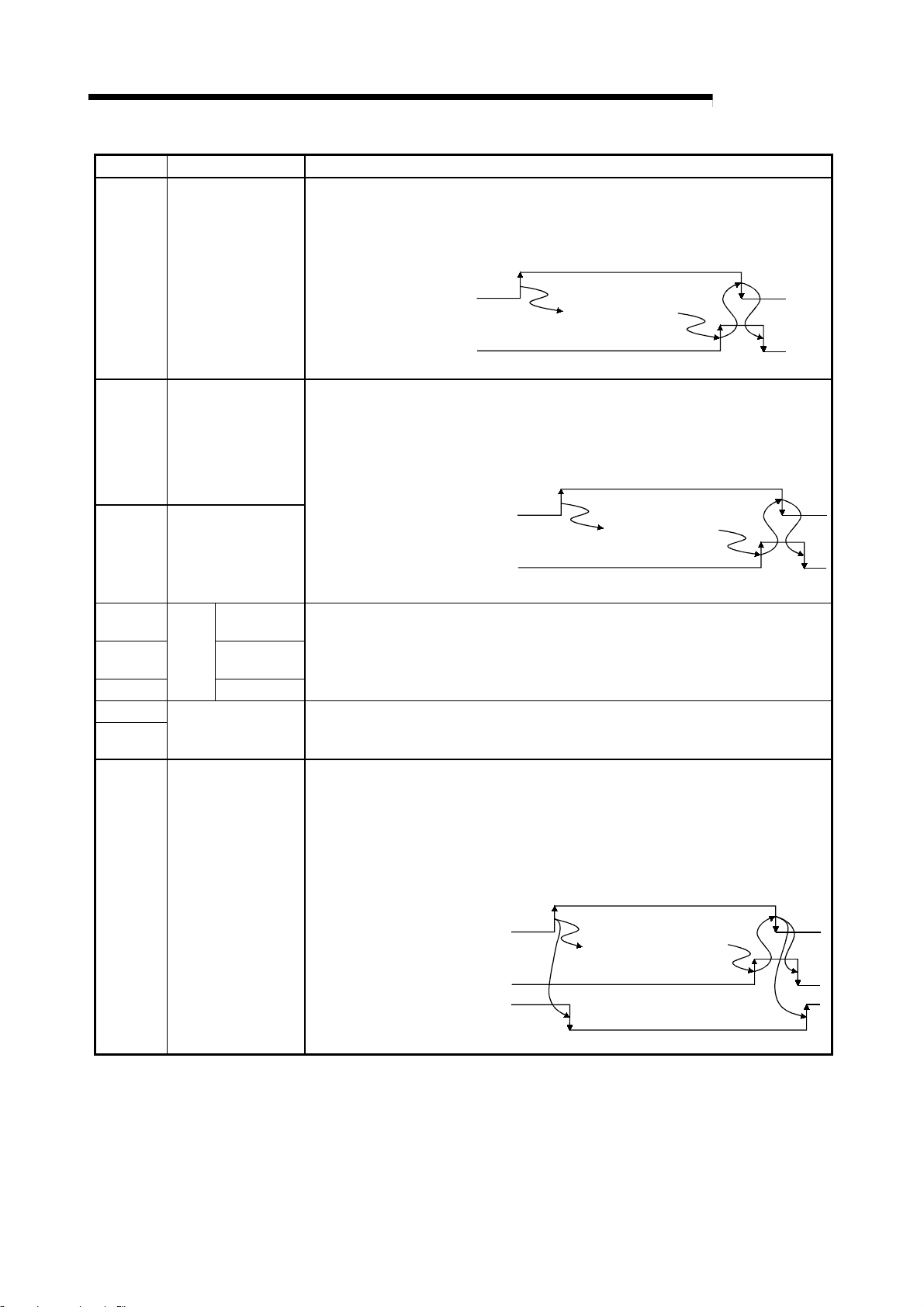
Device No. Signal name Details
The OS reception area clear request (RYn6) is turned ON to abort the data in the R2
OS reception area.
When OS reception area clear is completed, the R2 turns the OS reception area clear
complete (RXn6) ON, so the OS reception area clear request (RYn6) will turn OFF.
MELSEC-
RXn6
RXn7
RXn8
RXn9
RXnA
RXnB
RXnC
RXnD
OS reception area
clear complete
EEPROM function
normal complete
EEPROM function
error complete
CS (CTS)
signal
Signal
status
DR (DSR)
signal
CD signal
General-purpose
external input signal
OS reception area
clear request (RYn6)
OS reception area
clear complete (RXn6)
R2 clears the OS
reception area.
When the R2 EEPROM function is executed, after the data is read into the R2 buffer
memory (1C0
H), EEPROM function request (RYn7) turns ON.
When completed normally, EEPROM function normal complete (RXn7) turns ON.
When completed abnormally, EEPROM function error complete (RXn8) turns ON.
When these signals turn ON, EEPROM function request (RYn7) turns OFF.
EEPROM function request (RYn7)
EEPROM function normal complete
(RXn7)
or EEPROM function error complete
(RXn8)
R2 executes
EEPROM function.
This signal indicates the control signal status (CS, DR, CD signal) during RS-232-C
communication with an ON or OFF state.
This signal indicates the status of the R2 general-purpose external input (XC, XD)
status with an ON or OFF state.
RXnC: Corresponds to XC RXnD: corresponds to XD
When writing in the initialization data before executing initialization, the initial data read
request (RY(N+1)9) turns ON, and the initialization data is written to the master station.
At this time, remote station ready (RX(n+1)B) turns OFF.
When the writing is completed, initial data read complete (RX(n+1)9) turns ON, and
the initial data read request (RY(n+1)9) turns OFF.
When these turn OFF, initial data read complete (RX(n+1)9) turns OFF, and remote
station ready (RX(n+1)B) turns ON.
RX(n+1)9
Initial data read
complete
Initial data read request (RY(n+1)9)
Initial data read complete
(RX(n+1)9)
Remote station ready (RX(n+1)B)
3 - 9
R2 writes initialization
data to master station.
Page 30
A
3 SPECIFICATIONS
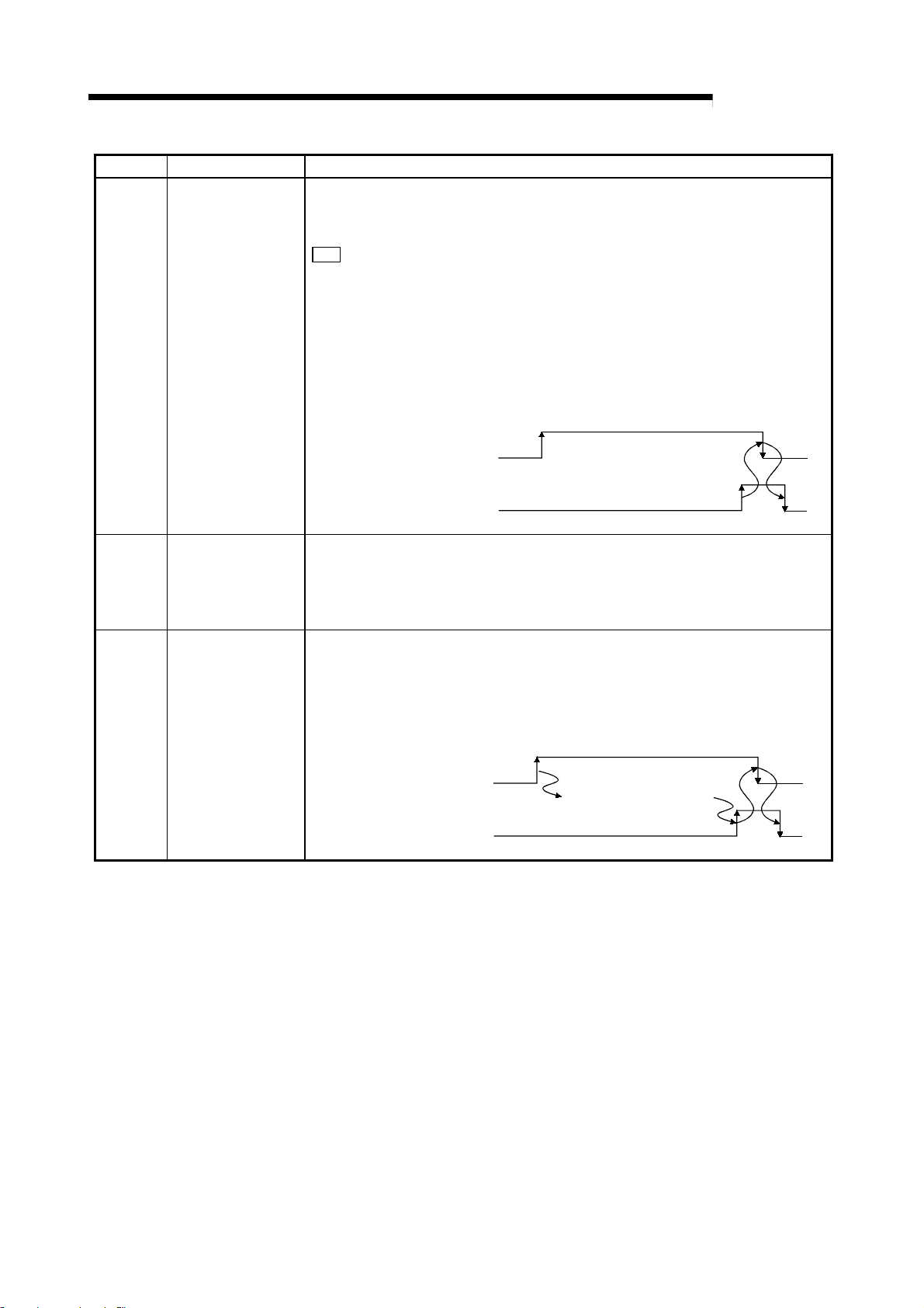
Device No. Signal name Details
This signal indicates the R2 error state.
If the R2 ERR.LED is lit, the error status (RX(n+1)A) turns ON, and when the
ERR.LED is OFF, the status turns OFF.
When an error occurs, the R2 stores the error code in the error code storage area
R2
1A8H to 1B2H).
(
When the error reset request (RY(n+1)A) is turned ON after remedying the error
cause, the error status (RX(n+1)A) can be turned OFF.
When the initialization error complete (RXn5) is ON, review the R2 initial setting and
turn ON the initialization request (RYn4) again to reinitialize the setting.
RX(n+1)A Error state
When the reinitialization is completed normally and the initialization normal complete
(RXn4) turns ON, the error state (RX(n+1)A) turns OFF.
(When the initialization error complete (RXn5) is ON, turning ON the error reset
request (RY(n+1)A) will not turn OFF the error state (RX(n+1)A).)
Error state (RX(n+1)A)
Any error cause
Error reset request (RY(n+1)A)
MELSEC-
RX(n+1)B Remote station ready
Intelligent device
RX(n+1)E
station access
complete
This signal indicates that the R2 can operate. (Refer to the section for RX(n+1)9.)
ON : The R2 is in the operatable state, and the initial data read request (RY(n+1)9)
is OFF.
OFF : An R2 initialization error occurred (R2 buffer memory setting value error), or
when the initial data read request (RY(n+1)9) is turned ON.
This signal indicates the R2 access complete state in response to the intelligent device
station access request (RY(n+1)E).
If not using dedicated commands and directly reading/writing from the programmable
controller CPU to the master station buffer memory, when accessing to the R2 is
completed, the R2 will turn intelligent device station access complete (RX(n+1)E) ON.
With this signal, the intelligent device station access request (RY(n+1)E) will turn OFF.
Intelligent device station
access request (RY(n+1)E)
Intelligent device station
access complete (RX(n+1)E)
Access to the intelligent
device station
3 - 10
Page 31

A
3 SPECIFICATIONS
(
)
(2) Remote output (RY)
Device No. Signal name Details
RYn0 Transmission request Refer to the sections on RXn0 and RXn1.
To cancel the transmission after requesting transmission from R2, the transmission
will be canceled when the transmission cancel request (RYn1) turns ON.
When the transmission is forcibly canceled, the transmission normal complete (RXn0)
or transmission error complete (RXn1) will turn ON.
When these turn ON, the transmission request (RYn0) and transmission cancel
request (RYn1) will turn OFF.
MELSEC-
RYn1
RYn2
RYn3
Transmission cancel
request
Reception read
complete
Forced reception
complete request
Transmission request (RYn0)
Transmission normal complete
(RXn0)
or Transmission error complete
(RXn1)
Transmission cancel request
RYn1
R2 is transmitting
contents of transmission
area to external device.
Forcibly cancels transmission.
Refer to the sections on RXn2 and RXn3.
When the forced reception complete request (RYn3) turns ON, reception from the
external device will be forcibly completed.
When the forced reception is completed, the reception normal read request (RXn2)
and reception error read request (RXn3) will turn ON.
When these turn ON, forced reception complete request (RYn3) will turn OFF and
reception read complete (RYn2) will turn ON.
When the reception read complete (RYn2) turns ON, the reception normal read
request (RXn2) and reception error read request (RXn3) will turn OFF.
When this turns OFF, reception read complete (RYn2) will turn OFF.
Forced reception complete
request (RYn3)
Reception normal read request
(RXn2)
or Reception error read request
(RXn3)
Forcibly completes
the reception.
Receiving data
Reception read complete (RYn2)
Reads reception area with program.
RYn4 Initialization request Refer to the sections on RXn4 and RXn5.
RYn6
RYn7
OS reception area
clear request
EEPROM function
request
Refer to the section on RXn6.
Refer to the sections on RXn7 and RXn8.
3 - 11
Page 32

A
3 SPECIFICATIONS
Device No. Signal name Details
This signal turns the RS (RTS) signal of the RS-232-C line ON or OFF.
RYn9
Signal
setting
RYnA
RYnC
RYnD
RY(n+1)9
RY(n+1)A Error reset request Refer to the section on RX(n+1)A.
RY(n+1)E
General-purpose
external output signal
Initial data read
request
Intelligent device
station access
request
RS(RTS)
signal *
ER(DTR)
signal *
Note that when "RS (RTS) signal status designation (
(0)", the signal will remain ON even if the RS signal setting (RYn9) is turned ON or
1
OFF.
When controlling the RS signal with the RS (RTS) signal, set the above buffer memory
to "Follow RYn9 ON/OFF (1)".
This signal turns the ER (DTR) signal of the RS-232-C line ON or OFF.
When using DTR/DSR (ER/DR) control, even if the ER (DTR) signal (RYnA) is turned
ON or OFF, the process will follow the flow control designation (R2 100H) setting.
2
If the ER signal is being controlled with the ER (DTR) signal (RYnA) set the above
buffer memory to "No flow control (0)" or "Executing flow control by the DC code
control (2)".
This signal indicates the status of the R2 general-purpose output (YC, YD) with an ON
or OFF state.
RYnC: Corresponds to YC RYnD: Corresponds to YD
Refer to the section on RX(n+1)9.
Refer to the section on RX(n+1)E.
MELSEC-
R2
101H)" is set to "Always ON
3 - 12
Page 33

3 SPECIFICATIONS
3.7 R2 buffer memory li st
The entire configuration of the R2 buffer memory is explained in this section.
The contents of the R2 buffer memory are cleared to the default values when the
power is turned OFF.
However, if the user has registered the default values in the R2 EEPROM, the
EEPROM default values will be written in when the power is turned ON.
Refer to section 8.8 for details on writing to the R2 EEPROM.
Refer to the buffer memory list in the following manner.
MELSEC-A
Address
(hexadecimal)
Name
Default
value
Update
Initializa tion
EEPROM
registration
Referenc
(7)(1) (2) (3) (4) (5) (6)
e
No. Name Details
(1) Address Indicates R2 buffer memory address as a hex adecimal.
(2) Name Indicates the name of the R2 buffer memory.
(3) Default value Indicates the default value at R2 shipment.
Indicates whether the R2 buffer memory value is updated by the master
station or R2.
(4) Update
M station : Updated by the master station
R2 : Updated by R2
Both : Updated by both master stati on and R2
Indicates whether initialization is required when the R2 buffer memory
values have been changed.
(5) Initialization
Refer to section 8.6 for details on initialization.
Required : Initialization is required.
Not required : Initialization is not re quired.
Indicates whether the contents of the R2 buffer memory can be
registered in the R2 EEPROM.
Refer to section 8.8 for details on registering to the EEPROM.
Possible : Registration to the EEPROM is possible.
Not possible : Registration to the EEPROM is not possible.
(6)
EEPROM
registration
(7) Reference Indicates the chapter, section or page containing detailed explanations.
3 - 13
Page 34

3 SPECIFICATIONS
(1) Area for designating various assignments
MELSEC-A
Address
(hexadecimal)
R2
H
H
H
H
4H to F
H
H
H
H
H
H
H
H
H
H
H
H
H
H
H
H
H
H
H
H
H
H
H
H
R2 0
R2 1
R2 2
R2 3
R2 10
R2 11
R2 12
R2 13
R2 14
R2 15
R2 16
R2 17
R2 18
R2 19
R2 1A
R2 1B
R2 1C
R2 1D
R2 1E
R2 1F
R2 20
R2 21
R2 22
R2 23
R2 24
R2 25
R2 26
R2 27
Name
Transmission area head
address designation
Transmission area size
Head address
designation area
designation
Reception area head
address designation
Reception area size
designation
H
System area (Use prohibited) – – – – –
Transmission size 20
Status
storage
area
R2 side head address 1A0
(Fixed value: 4004H) 4004
Master station side offset
address
Transmission size 88
Transmission area 1
R2 side head address 118
(Fixed value: 4004H) 4004
Master station side offset
address
Transmission size 200
Transmission area 2
Automatic
update area
designation
Reception
area
R2 side head address 200
(Fixed value: 4004H) 4004
Master station side offset
address
Transmission size 200
R2 side head address 400
(Fixed value: 4004H) 4004
Master station side offset
address
Transmission size 1A0
Initial setting
area
R2 side head address 0
(Fixed value: 4004H) 4004
Master station side offset
address
Transmission size 30
EEPROM
function
area
R2 side head address 1C0
(Fixed value: 4004H) 4004
Master station side offset
address
Default
value
200
200
400
200
H
1A0
H
118
200
400
H
H
0
H
1C0
Update
H
H
M station Required Possible
H
H
H
H
H
H
H
H
H
H
H
H
M station Required Possible
H
H
H
H
H
H
H
H
H
Initializa-
tion
EEPROM
registration
Reference
Section
6.1
Section
6.2
Section
5.6.2
3 - 14
Page 35

3 SPECIFICATIONS
MELSEC-A
Address
(hexadecimal)
R2
R2
R2
R2
R2
R2
34H to
H
4BH to
H
72H to
H
7CH to
H
F8H to
H
30
H
H
H
H
H
H
H
H
H
H
H
H
H
H
H
H
H
H
H
H
H
H
H
H
H
H
H
H
H
H
H
R2 28
R2 29
R2 2A
R2 2B
R2 2C
R2 2D
R2 2E
R2 2F
R2 31
R2 32
R2 33
3F
R2 40
R2 41
R2 42
R2 43
R2 44
R2 45
R2 46
R2 47
R2 48
R2 49
R2 4A
6F
R2 70
R2 71
77
R2 78
R2 79
R2 7A
R2 7B
F5
R2 F6
R2 F7
FF
Automatic
update area
designation
User
registration
frame area
Monitor
transmission area 1
Monitor
transmission area 2
Name
Transmission size 29
R2 side head address 1C7
(Fixed value: 4004H) 4004
Master station side offset
address
Transmission size 88
R2 side head address 118
(Fixed value: 4004H) 4004
Master station side offset
address
Transmission size 200
R2 side head address 200
(Fixed value: 4004H) 4004
Master station side offset
address
Default
value
H
1C7
H
118
200
Update
H
H
H
H
M station Required Possible
H
H
H
H
H
H
Initializa-
tion
EEPROM
registration
Reference
Section
5.6.2
System area (Use prohibited) – – – – –
RW update interval time designation 1
RWw update validity designation 0
RWr update validity designation 1
H
H
H
M station Required Possible
H
H
H
H
H
Section
8.5
RW refresh
destination address
designation
Master station R2 (RWw0) 118
R2 Master station (RWr0) 1B0
Master station R2 (RWw1) 119
R2 Master station (RWr1) 1B1
Master station R2 (RWw2) 120
R2 Master station (RWr2) 1B2
Master station R2 (RWw3) 121
Master station (RWr3) 1B6
R2
System area (Use prohibited) – – – – –
Monitor interval time designation 0
No. of monitor designation 0
M station Required Possible
Section
7.4
System area (Use prohibited) – – – – –
Monitor
designation –1
Monitor
designation –2
Monitor target designation 0
Transmission data designation 0
Monitor target designation 0
Transmission data designation 0
M station Required Possible
Section
7.4
0
Monitor
designation –64
Monitor target designation 0
Transmission data designation 0
System area (Use prohibited) – – – – –
3 - 15
Page 36

3 SPECIFICATIONS
(2) Parameter area
MELSEC-A
Address
(hexadecimal)
106H to
H
113H to
H
11BH to
H
120
123H to
H
186H to
H
19DH to
H
H
H
H
H
H
H
H
H
H
H
H
H
H
H
H
H
H
H
H
H
H
H
H
R2 100
R2 101
R2 102
R2 103
R2 105
R2
107
R2 108
R2 109
R2 10A
R2 10B
R2 10C
R2 10D
R2 10E
R2 10F
R2 110
R2 111
R2 112
R2
117
R2 118
R2 119
R2 11A
R2
11F
R2
R2 121
R2 122
R2
184
R2 185
R2
18F
R2
19F
Name
Default
value
Flow control designation 1
RS (RTS) signal status designation 0
Word/byte unit designation 0
ASCII-BIN conversion designation 0
Transient timeout time designation 0
Update
M station Required Possible
Initializa-
tion
EEPROM
registration
Reference
Section
8.3
Section
8.9
Section
6.1, 6.2
Section
8.4
Section
5.6.1
System area (Use prohibited) – – – – –
0
Reception head frame No.
0
0
0
Section
7.3
Reception end frame No.
H
A
H
D
M station Required Possible
0
0
Reception head frame/reception end frame abort
designation
Reception end data size designation 0
Reception timeout time designation 0
1
Section
6.2
System area (Use prohibited) – – – – –
Transmission
frame - 1 area
Transmission timeout time designation 0
Transmission head frame No. 0
Transmission end frame No. 0
M station
Not
required
Possible
Section
7.2.1
Section
6.1
System area (Use prohibited) – – – – –
Transmission table head No.
designation
0
No. of transmission tables 0
Transmission
frame - 2 area
Transmission table
designation
No. 1
M station
0
Not
required
Possible
Section
7.2.2
No.100
System area (Use prohibited) – – – – –
System area (Use prohibited) – – – – –
3 - 16
Page 37

3 SPECIFICATIONS
(3) Setting status storage area
MELSEC-A
Address
(hexadecimal)
R2 1A0
R2 1A1
R2 1A2
R2 1A3
R2 1A4
R2 1A5
R2 1A6
R2 1A7
H
Station No. setting switch
H
Data link transmission speed setting sw itch
H
Mode setting switch
H
RS-232-C transmission speed
H
RS-232-C data bit length
H
RS-232-C parity bit presence
H
RS-232-C stop bit length
H
Buffer memory default value setting status storage 0
*1 Follows switch setting
Address
(hexadecimal)
R2
1A8H to
H
1AF
Error code
1B7H to
H
H
storage area
H
H
H
System area (Use prohibited) – – – – –
H
Actual transmission data size storage 0
H
Reception frame index No. storage 0
No. of data items in OS reception area data size
H
storage
System area (Use prohibited) – – – – –
H
Software version storage
R2 1B0
R2 1B1
R2 1B2
R2 1B3
R2 1B4
R2 1B5
R2 1B6
R2
1BE
R2 1BF
Name
Default
value
1
*
(4) Communication status storage area
Name
Error code history 0
General error code 0
Error code at transmission 0
Error code at reception 0
Default
value
0
Follows
version
Update
R2
Update
R2
R2
R2
Initializa-
tion
Not
required
Initializa-
tion
Not
required
Not
required
Not
required
EEPROM
registration
Not
possible
EEPROM
registration
Not
possible
Not
possible
Not
possible
Reference
Section
8.10
Section
8.8
Reference
Section
10.1.1
Section
6.1
Section
7.3
Section
6.2
Section
8.10
3 - 17
Page 38

3 SPECIFICATIONS
(5) EEPROM area
MELSEC-A
Address
(hexadecimal)
R2 1C0
R2 1C1
R2
1C6
R2 1C7
R2
1EF
R2
1FF
H
H
1C2H to
H
H
1C8H to
H
1F0H to
H
Address
(hexadecimal)
R2 200
R2
3FF
R2 400
R2
5FF
R2
7FF
R2
F1F
H
201H to
H
H
401H to
H
600H to
H
800H to
H
Name
Default
value
Update
Initializa-
tion
EEPROM
registration
Reference
Section
EEPROM function designation 0
User-registered frame No. designation 0
M station
Not
required
Not
possible
8.8 and
Section
7.5.2
Section
7.5.2
System area (Use prohibited) – – – – –
User-registered frame byte designation 0
User-registered frame 0
Both
Not
required
Not
possible
Section
7.5.2
System area (Use prohibited) – – – – –
(6) User free area
Name
Default
value
Update
Default transmission data size designation area 0
Default transmission data designation area 0
M station
Default reception data size designation area 0
Default reception data designation area 0
Follows
transmis-
Area not used at default 0
sion/
reception
area
setting
System area (Use prohibited) – – – – –
R2
Initializa-
tion
Not
required
Not
required
Not
required
EEPROM
registration
Not
possible
Not
possible
Not
possible
Reference
Section
6.1
Section
6.2
Chapter 6
3 - 18
Page 39

3 SPECIFICATIONS
×
×
×
×
×
×
×
×
3.8 Transmission delay time
The transmissio n de lay ti me (t i me fo r da ta to be conveyed) is shown below.
(1) Calculation expressions
Master station (RX/RWr) R2 (RX/RWr) SM + LS
Master station (RY/RWw) R2 (RY/RW w)
Master station (RX) G eneral-purpose input
Master station G eneral-purpose output
Details
(RXnC, RXnD)
(RYnC, RYnD)
Calculation expression (unit: ms)
When the master
station is the A/QnA
Series
SM + LS
3 + RS
SM + LS
SM + LS
station is the Q Series
3 + 10
MELSEC-A
When the master
3 + RS
SM + LS
3 + 2
2 + RS
SM : Master station sequence program's scan time
LS : Link scan time (Refer to Master Module User's Manual)
RS : R2 internal processing time *
1
*1 R2 internal processing time
The R2 internal processing time is calculated with the following equation.
R2 internal processing time (R2) = LS
Transmission
speed
K (constant) 2 2 4 8 32
156kbps 625kbps 2.5Mbps 5Mbps 10Mbps
K (constant)
(2) Calculation example
An example for calculating the transmission delay time from the master station
(RX/RWr) to R2 (RX/RWr).
When only one R2 is connected with SM: 20ms, and transmission speed:
156kbps
(a) When the master station is the A/QnA Seri es
LS : 51.2 {29.4 + (8 × 4.8) + (8 × 9.6) + (1 + 32.4) + (1 × 4.8) + (1 × 9.6)} +
=
1300
11100µs (11.1ms)
20 + 11.1
3 + 11.1 × 2 = 75.5ms
(b) When the master station is the Q Series
LS : 51.2 {27 + (8 × 4.8) + (8 × 9.6) + (1 × 30) + (1 × 4.8) + (1 × 9.6)} +
1300 + 0 + 0
20 + 10.9
2 + 10.9 × 2 = 63.6ms
=
10854µs (10.9ms)
3 - 19
Page 40

3 SPECIFICATIONS
×
×
×
×
>
>
3.9 Transmission/reception time
The transmissio n/r ec ep ti on t i me is shown below.
3.9.1 When using buffer memory automatic update functi on
The transmission time is the time from when the transmission request (RYn0) turns ON
to when the R2 turns the transmission normal complete (RXn0) ON.
The reception time is the time from when the R2 starts receiving the data to when the
reception normal read request (RXn2) and reception error read request (RXn3) are
turned ON by the R2.
(1) Calculation expressions
Details Calculation expression (unit: ms)
2 + LS × 6 + RS + data transmission time *1 + request/response
SM
scan time of area to be updated at transmission *
SM + LS × 3 + RS + data reception time *1 + request/response scan
time of area to be updated at reception *
2 + LS × 4 + RS + data transmission time *1 + request/response
SM
scan time of area to be updated at transmission *
SM + LS
time of area to be updated at reception *
2 + RS + data reception time *1 + request/response scan
When the master station
is the A/QnA Series
When the master station
is the Q Series
Transmission time
Reception time
Transmission time
Reception time
MELSEC-A
2
2
2
2
SM : Master station sequence program's scan time
LS : Link scan time (Refer to Master Module User's Manual.)
RS : R2 internal processing time (Refer to section 3.8 (1).)
*1 Data transmission (reception) time
This time is obtained with the data size and RS-232-C transmission speed.
(Example) Data size: 200 bytes, Transmission speed: 9600bps (data bit length:
8, stop bit leng th : 1, pari ty bi t: even)
200
10/9600
=
0.208s
*2 Request/response scan of area to be updated at transmission (reception)
This is the response/request scan of each area automatically updated during
transmission (reception).
With the default value for transmission, the status storage area and transmission
area 1 and 2 are up dat ed . With t he re cept io n de fa ul t val ue, th e st atu s sto rage
area and reception area are updated.
<
Request/response scan of area where data is written from master station to R2
(Size of data to be au to mati cally updated + 16)/ 72 × LS [ms]
Decimal point rounded up
<
Request/response scan of area where data is written from R2 to master station
(Size of data to be au to mati cally updated + 16)/ 16 × LS [ms]
Decimal point rounded up
3 - 20
Page 41

3 SPECIFICATIONS
×
×
×
×
×
×
×
×
×
×
×
×
×
×
×
×
×
×
×
×
×
×
×
×
×
×
×
×
×
×
(2) Calculation example
MELSEC-A
(a) Transmission time
An example of calculating the transmission time for transmitting 10 words
(20 bytes) of data i s show n be low .
Item Setting details
Transmission size of each area Default value
Transmission speed 156kbps
No. of connected modules Only one R2 module
Master station sequence program scan time 20ms (Hypothetical)
Transmission speed 9600bps
Data bit length 8
Stop bit length 1
Parity bit Even
1) When the master station is the A /QnA ser ies
LS = 51.2 {29.4 + (8
=
+ 1300
11100µs (11.1ms)
4.8) + (8
9.6) + (1
32.4) + (1
4.8) + (1
9.6)}
=
Data transmission time = 20
Transmission time = 20
2 + 11.1
+ {(136 + 16)/72
+ {(32 + 16)/16
= 149.6 + 3
10/9600
11.1 + 8
0.0208s (20.8ms)
6 + (11.1
11.1} *
11.1} *
2) *
3
+ {(512 + 16)/72
5
11.1 + 3
= 305ms
2) When the master station is the Q seri es
LS = 51.2 {27 + (8
+ 1300 +0 +0
4.8) + (8
=
10854µs (10.9ms)
Data transmission time = 20
Transmission time = 20
2 + 10.9
+ {(136 + 16)/72
+ {(32 + 16)/16
= 126.2 + 3
= 278.8ms
*1R2 (R2 internal processing time)
2
*
Data transmission time
3
*
Transmission area 1 request/response scan (88H (136 word s)
worth)
4
Transmission area 2 request/response scan (200H (512 words)
*
worth)
5
Status storage area request/response scan (20H (32 wor ds )
*
worth)
9.6) + (1
10/9600
10.9 + 8
30) + (1
=
0.0208s (20.8ms)
4 + (10.9
10.9} *
10.9} *
2) *
3
+ {(512 + 16)/72
5
10.9 + 3
1
+ 20.8 *
11.1
4.8) + (1
1
+ 20.8 *
10.9
2
2
9.6)}
11.1} *
10.9} *
4
4
3 - 21
Page 42

3 SPECIFICATIONS
×
×
×
×
×
×
×
×
×
×
×
×
×
×
×
×
×
×
×
×
×
×
×
×
MELSEC-A
(b) Reception time
An example for calculating the reception time when receiving 10 words (20
bytes) of data is shown below.
Item Setting details
Transmission size of each area Default value
Transmission speed 156kbps
No. of connected modules Only one R2 module
Master station sequence program scan time 20ms (Hypothetical)
Transmission speed 9600bps
Data bit length 8
Stop bit length 1
Parity bit Even
1) When the master station is the A /QnA ser ies
LS = 51.2 {29.4 + (8
=
+ 1300
11100µs (11.1ms)
4.8) + (8
9.6) + (1
32.4) + (1
4.8) + (1
9.6)}
=
Data receptio n ti me = 20
10/9600
Reception time = 20 + 11.1
+ {(32 + 16)/16
= 96.3 + 3
0.0208s (20.8ms)
3 + (11.1
11.1} *
11.1 + 33
1
+ 20.8 *
2) *
3
+ {(512 + 16)/16
11.1 = 495.9 ms
2) When the master station is the Q seri es
LS = 51.2 {27 + (8
+ 1300 + 0 + 0
Data receptio n ti me = 20
4.8) + (8
=
10854µs (10.9ms)
10/9600
Reception time = 20 + 10.9
+ {(32 + 16)/16
= 84.4 + 3
*1 RS (R2 internal processing time)
*2 Data transmission time
*3 Status storage area request/response scan (20
worth)
*4 Reception area request/response scan (200
worth)
9.6) + (1
2 + (10.9
10.9 + 33
30) + (1
=
0.0208s (20.8ms)
1
+ 20.8 *
2) *
3
10.9} *
+ {(512 + 16)/16
10.9 = 476.8 ms
2
4.8) + (1
2
H
(512 words)
11.1} *
9.6)}
10.9} *
H
(32 wor ds )
4
4
3 - 22
Page 43

3 SPECIFICATIONS
×
×
×
×
3.9.2 When using transmission/reception buffer
The transmission time is the time from when the transmission data is stored in the R2,
the transmission request (RYn0) is turned ON to when the transmission normal
complete (RXn0) is turned ON by the R2.
The reception time is the time from when the R2 starts receiving the data, the reception
normal read request (RXn2) and reception error read request (RXn3) are turned ON by
the R2, to when the data is received.
(1) Calculation expression
Details Calculation expression (unit: ms)
SM + 2 + LS
transmission time*
SM + LS × 3 + RS + data reception time *1 + transient transmission
2
time*
SM + 2 + LS
transmission time*
SM + LS
2
time*
When the master station
is the A/QnA Series
When the master station
is the Q Series
Transmission time
Reception time
Transmission time
Reception time
MELSEC-A
6 + RS + data transmission time *1 + transient
2
4 + RS + data transmission time *1 + transient
2
2 + RS + data reception time *1 + transient transmission
SM : Master station sequence program's scan time
LS : Link scan time (Refer to Master Module User's Manual)
RS : R2 internal processing time (Refer to section 3.8 (1))
*1 Data transmission (reception) time
This time is obtained with the data size and RS-232-C transmission speed.
(Example) Data size: 200 bytes, transmission speed: 9600bps (data bit length:
8, stop bit leng th : 1, pari ty bi t: even)
200
10/9600
=
0.208s
*2 Transient transmission time
During transmission, this is the time for the data to be written from the master
station to the R2.
During reception, this is the time for reading the data from the R2 to the master
station.
Refer to section 5.4.3 in the Q Series Master Module User's Manual for the
calculation expressions.
3 - 23
Page 44
3 SPECIFICATIONS
×
×
×
×
×
(2) Calculation example
MELSEC-A
(a) Transmission time
An example of calculating the transmission time for transmitting 10 words
(20 bytes) of data i s show n be low .
Item Setting details
Transmission speed 156kbps
No. of connected modules Only one R2 module
Master station sequence program scan time 20ms (Hypothetical)
Transmission speed 9600bps
Data bit length 8
Stop bit length 1
Parity bit Even
1) When the master station is the A /QnA ser ies
LS = 51.2 {29.4 + (8 × 4.8) + (8 × 9.6) + (1 × 32.4) + (1 × 4.8) + (1 × 9.6)}
=
+ 1300
11100µs (11.1ms)
Data transmission time = 20
Transmission time = 20
10/9600 = 0.0208s (20.8ms)
2 + 11.1 × 6 + (11.1 × 2) *1 + 20.8 *
2
+ {20 + 11.1 + (11 + 16)/72 × 11.1 + 11.1 + 20
+ 11.1
2 + 11.1 + 11.1 + 11.1} × 1 *
3
= 149.6 + (20 + 11.1 + 11.1 + 11.1 + 20 + 22.2 + 11.1
+ 11.1 + 11.1)
= 149.6 + 128.8
= 278.4ms
2) When the master station is the Q seri es
LS = 51.2 {27 + (8 × 4.8) + (8 × 9.6) + (1 × 30) + (1 × 4.8) + (1 × 9.6)}
=
+ 1300 + 0 + 0
Data transmission time = 20
Transmission time = 20
*1 R2 (R2 internal processing time)
*2 Data transmission time
*3 Transient transmission time (10 words + 1 word (transmission
data size) worth)
10854µs (10.9 ms)
10/9600 = 0.0208s (20.8ms)
2 + 10.9 × 4 + (10.9 × 2) *1 + 20.8 *
+ 1 + 10.9 × [6 + {(11 + 16) / 72} × 1.13] *
= 126.2 + 78.717
= 204.917
= 205.0ms
2
3
3 - 24
Page 45

3 SPECIFICATIONS
×
×
×
×
×
MELSEC-A
(b) Reception time
An example for calculating the reception time when receiving 10 words (20
bytes) of data is shown below.
Item Setting details
Transmission speed 156kbps
No. of connected modules Only one R2 module
Master station sequence program scan time 20ms (Hypothetical)
Transmission speed 9600bps
Data bit length 8
Stop bit length 1
Parity bit Even
1) When the master station is the A /QnA ser ies
LS = 51.2 {29.4 + (8 × 4.8) + (8 × 9.6) + (1 × 32.4) + (1 × 4.8) + (1 × 9.6)}
=
+ 1300
11100µs (11.1ms)
Data receptio n ti me = 20
Reception time = 20 + 11.1
10/9600 = 0.0208s (20.8ms)
3 + (11.1 × 2) *1 + 20.8 *
2
+ {20 + 11.1 + 11.1 + 11.1 + 20 + 11.1 × 2 + (10
+ 16)/16
11.1 + 11.1 + 11.1} × 1 *
3
= 96.3 + (20 + 11.1 + 11.1 + 11.1 + 20 + 22.2 + 11.1
+ 11.1)
= 96.3 + 139.9
= 236.2ms
2) When the master station is the Q seri es
LS = 51.2 {27 + (8 × 4.8) + (8 × 9.6) + (1 × 30) + (1 × 4.8) + (1 × 9.6)}
=
+ 1300 + 0 + 0
Data transmission time = 20
Transmission time = 20
*1 R2 (R2 internal processing time)
*2 Data transmission time
*3 Transient transmission time (10 words worth)
10854µs (10.9 ms)
10/9600 = 0.0208s (20.8ms)
2 + 10.9 × 2 + (10.9 × 2) *1 + 20.8 *
+ 1 + 10.9 × [6 + {(10 + 16) / 16} × 1.067] *
= 84.4 + 89.6606
= 174.0606
=
174.1ms
2
3
3 - 25
Page 46

3 SPECIFICATIONS
MEMO
MELSEC-A
3 - 26
Page 47

A
4 PROCEDURES AND SETTINGS BEFORE OPERATION
4. PROCEDURES AND SETTINGS BEFORE OPERATION
The operation procedures before starting the R2 operation, names and settings of
each R2 section, wiring method and hardware test are described in this section.
4.1 Procedures before operation
The procedures before operating the R2 are explained below.
Start
MELSEC-
Test the R2 hardware.
Hardware test normal
Test the master module hardware.
Hardware test normal
Connect the master module and module, such as the R2, with a CC-Link
dedicated cable.
Connect the R2 and external device with an RS-232-C cable.
Set each switch on the master module.
* When using the AJ61BT11 or A1SJ61BT11, set SW8 of the condition setting
switch OFF (intelligent mode).
Set each switch on the R2.
Turn the power ON in the order of the external device, R2 and master module.
Test the data link line with the master module.
Line test normal
Refer to section 4.6.
4
Refer to section 4.5.
Refer to master module manual.
Refer to section 4.4.
Refer to master module manual.
(Continued on next page)
4 - 1
Page 48

A
4 PROCEDURES AND SETTINGS BEFORE OPERATION
(Continued from previous page)
Create a program.
1. Initializing the master module
2. Reading the remote input (RX)
3. Confirming the R2 data link state
4. Initializing the R2
5. Transmitting data to the external device
6. Exchanging data with the external device
7. Processing R2 errors
8. Writing in the remote output (RY)
Start the data link.
Completed.
(Refer to Section 5.4.)
(Refer to Section 5.3 (2).)
(Refer to Section 5.3 (3).)
(Refer to Section 5.5.)
(Refer to Section 6.3.1, 6.4.1.)
(Refer to Section 6.3.2, 6.4.2.)
(Refer to Section 5.3 (7).)
(Refer to Section 5.3 (8).)
MELSEC-
4 - 2
Page 49

A
4 PROCEDURES AND SETTINGS BEFORE OPERATION
4.2 Precautions for handling
The precautions for handling the R2 are shown below.
MELSEC-
DANGER
CAUTION
• Do not touch the terminals or connectors while the power is ON.
Failure to observe this could lead to electric shocks or malfunctioning.
• Do not touch the connector inside the lid at the top of the module.
Failure to observe this could lead to module trouble or malfunctioning.
• Make sure that foreign matter, such as cutting chips or wire scraps, do not enter the
module.
Failure to observe this could lead to fires, trouble or malfunctioning.
• Never disassemble or modify the module.
Failure to observe this could lead to trouble, malfunctioning, injuries or fires.
• The module case is made of resin, so do not drop it or apply strong impacts on it.
Failure to observe this could lead to module damage.
• Tighten the terminal screws within the specified torque range.
A loose terminal screw could lead to short-circuiting or malfunctioning.
If the terminal screw is too tight, short-circuiting or malfunctioning could occur due to
screw damage.
• Dispose of this product as industrial waste.
• Use this module within the general specification environment described in the
manual.
Use in an environment outside the general specification range could lead to electric
shocks, fires, malfunctioning, product damage or deterioration.
• Securely fix the module with the DIN rail or installation screw. Tighten the installation
screw within the designated torque range.
A loose screw could lead to dropping, short-circuiting or malfunctioning.
If the screw is too tight, dropping or short-circuiting could occur due to screw
damage.
• Before installing or removing the module on the panel, be sure to shut off all phases
of external power supply used by the system.
Failure to shut off all phases could lead to module trouble or malfunctioning.
4 - 3
Page 50

A
4 PROCEDURES AND SETTINGS BEFORE OPERATION
⋅
⋅
⋅
⋅
(1) Tighten the module installation screws and terminal block screws
within the following range.
Screw place Tightening torque range Remarks
Module installation screw (M4 screw)
Terminal block terminal screw (M3.5 screw)
Terminal block installation screw (M4 screw)
RS-232-C cable connector screw (M2.6 screw)
0.78 to 1.18N
0.59 to 0.88N
0.98 to 1.37N
0.20 to 0.39N
(2) When using the DIN rail adaptor, install the DIN rail while observing
the following points.
(a) Applicable DIN rail type (JIS C 2812 compliant)
TH35-7.5Fe
TH35-7.5Al
TH35-15Fe
MELSEC-
m
m
m
Screw hole depth: L=3.2mm or less
m
(Internal dimension from end face)
-
-
-
(b) DIN rail installation screw pitch
When installing the DIN rail, tighten the screws at a pitch of 200mm or less.
4 - 4
Page 51

A
4 PROCEDURES AND SETTINGS BEFORE OPERATION
4.3 Installation environment
When installing the programmable controller, refer to the CC-Link system master
module's User's Manual.
MELSEC-
4 - 5
Page 52

A
4 PROCEDURES AND SETTINGS BEFORE OPERATION
(7)
(6)
(8)
4.4 Names of each part, and settings
The names of the parts in the R2, the LED details, and the settings for each switch are
explained in this section.
MELSEC-
(10)
(1) (3) (2)
(4)
No. Name Details
(1) Operation display LEDs
LED name Details
Default
state
State L ERR.
Others
XC, XD
YC, YD
RS-232-C SD
RS-232-C RD
RS-232-C
ERR.
ON: Power is ON. OFF: Power is OFF.
PW
ON: Operating normally OFF: Power (24VDC) is OFF, WDT error is occurring or
RUN
ON: Communicating normally OFF: Communication stopped (Time over error) or the
L RUN
ON: Any transmission speed or station number out of range is set.
Flickering at constant intervals : The transmission speed or station number has been
Flickering not constant intervals : The terminating resistor is not connected. The module or
OFF: Communicating normally
SD ON, Flashing: Data link Sending data OFF: Data link Not sending data
RD ON, Flashing: Data link Receiving data OFF: Data link Not receiving data
ON: General-purpose input (XC, XD) is ON.
OFF: General-purpose input (XC, XD) is OFF.
ON: General-purpose output (YC, YD) is ON.
OFF: General-purpose output (YC, YD) is OFF.
ON, Flashing: Sending RS-232-C data
OFF: Not sending RS-232-C data
ON, Flashing: Receiving RS-232-C data
OFF: Not receiving RS-232-C data
ON: RS-232-C transmission error OFF: No error
the switch setting is incorrect.
switch setting is incorrect.
changed after the power is turned on.
CC-Link dedicated cable is being affected by noise.
(9)
(5)
4 - 6
Page 53

A
4 PROCEDURES AND SETTINGS BEFORE OPERATION
No. Name Details
(2) Station No. setting switch Set the module's station No. (Default setting: 0)
Setting range: 1 to 64 (0: Master module)
" 10" sets the 10th place of the station No..
1" sets the 1st place of the station No..
"
MELSEC-
(3) Data link transmission speed
setting switch
(4) Mode setting switch
Setting Transmission speed
0 156kbps
1 625kbps
22.5Mbps
35Mbps
4 10Mbps
- Setting error
Set the module's transmission speed (for data
link)
(Default setting: 0)
Set the module's operation state. (Default setting: 0)
No. Name Setting details
On-line mode (using
0
transmission/reception buffer)
On-line mode (using buffer memory
1
automatic update function)
2 Not used Setting error ("RUN" LED turns OFF.)
3 Not used Setting error ("RUN" LED turns OFF.)
4 Use not possible –
5 Not used Setting error ("RUN" LED turns OFF.)
6 Not used Setting error ("RUN" LED turns OFF.)
7 Not used Setting error ("RUN" LED turns OFF.)
8 Not used Setting error ("RUN" LED turns OFF.)
9 Not used Setting error ("RUN" LED turns OFF.)
A Not used Setting error ("RUN" LED turns OFF.)
B Not used Setting error ("RUN" LED turns OFF.)
C Not used Setting error ("RUN" LED turns OFF.)
D Hardware test mode Mode for confirming that module runs independently.
E Not used Setting error ("RUN" LED turns OFF.)
F Not used Setting error ("RUN" LED turns OFF.)
Mode for on-line communication.
Set when using the transmission/reception buffer.
Mode for on-line communication.
Set when using the buffer memory automatic update function.
(5) RS-232-C transmission
specifications setting switch
Set the RS-232-C transmission specifications.
No. Setting details
SW 1 2 3
SW1 to 3 Transmission speed
SW4 Not used
SW5 Data bit length 8 7 ON
SW6 Yes No
Parity bit
SW7
SW8 Stop bit length 2 1
Setting switch state
ON OFF
0 0 0 300bps
1 0 0 600bps
0 1 0 1200bps
1 1 0 2400bps
0 0 1 4800bps
1 0 1 9600bps
0 1 1 19200bps
0:OFF 1:ON
Even Odd
Default
setting
OFF
OFF
(6) Data link terminal block Connect a CC-Link dedicated cable for power supply and data link. (2-piece terminal
block)
(7) RS-232-C interface Connect an RS-232-C cable for connection with external device.
(8) General-purpose input/output
Connect the input/output wire.
terminal block.
(9) Reset switch Returns to the power ON status.
(10) Connector Use prohibited.
4 - 7
Page 54

A
4 PROCEDURES AND SETTINGS BEFORE OPERATION
Ω
4.5 Wiring
4.5.1 Precautions for handling the CC-Link dedicated cables
Avoid the following extreme handling. Such handling will damage the CC-Link
dedicated cables.
• Compress the cable with a sharp edge.
• Twist the cable extremely.
• Pull the cable extremely hard. (More than permissible tension)
• Step on the cable.
• Put an object on the cable.
• Scratch the cable sheath.
4.5.2 Connection of the CC-Link dedicated cables
MELSEC-
CAUTION
• Before starting installation or wiring work, be sure to shut off all phases of external
power supply used by the system. Failure to shut off all phases could lead to electric
shocks, product damage or malfunctioning.
• Always install the terminal covers enclosed with the product before turning ON the
power or operating the product after installation or wiring work.
Failure to install the terminal cover could lead to electric shocks.
• Before cleaning or tightening the terminal screws, be sure to shut off all phases of
external power supply used by the system. Failure to shut off all phases could lead
to module trouble or malfunctioning. A loose screw could lead to dropping, shortcircuiting or malfunctioning. If the screw is too tight, dropping or short-circuiting
malfunctioning could occur due to screw damage.
• Do not bind the control wire or communication cable with the main circuit or power
wire, or place the control wire near these. Separate by at least 100mm or more.
Failure to observe this could lead to malfunctions caused by noise.
• Always ground the FG terminal with Class D grounding (grounding resistance :
100
or less) or higher dedicated of the programmable controller.
Failure to do so could lead to electric shock or malfunctioning.
• Always confirm the product's rated voltage and terminal layout before wiring the
module. Connecting with a power supply other than the rated power supply, or
incorrect wiring could lead to fires or trouble.
• Securely mount the connector of each connection cable to the mounting section.
An incomplete connection could lead to malfunctioning causes.
• Be sure to fix the wires or cables by ducts or clamps when connecting them to the
module. Failure to do so may cause damage of the module or the cables due to
accidental pull or unintentional shifting of the cables, or malfunctions due to poor
contact of the cable.
• Do not install the control lines together with the communication cables, or bring them
close to each other. Failure to do so may cause malfunctions due to noise.
• Always connect the master module and CC-Link dedicated cable at the data link
terminal block. If the data link terminal block and general-purpose output terminal
block are incorrectly inserted, module trouble could occur.
Data link terminal block
4 - 8
General-purpose input/
output terminal block
Page 55

A
4 PROCEDURES AND SETTINGS BEFORE OPERATION
The method of connecting the R2, master module and remote module with a CC-Link
dedicated cable is shown below.
MELSEC-
Master module R2
Terminator
DA
DB
DG
SLD
FG
(B)
(W)
(Y)
CC-Link dedicated
cable
POINT
Always connect the modules on both ends of the data link with the "terminator"
enclosed with the master module. (Connect across DA-DB)
4.5.3 Connection with external device
The method of connecting the R2 and external device with RS-232-C is show below.
(1) Example of connection for DC code control and DTR/DSR signal
control
DA
DB
DG
SLD
24V
24G
FG
CC-Link dedicated
cable
Remote module
DA
DB
DG
SLD
24V
24G
FG
Terminator
R2 side (DTE) External device (DTE)
Signal abbrev. Pin No.
Cable connection and signal method
SD 3 SD
RD 2 RD
RS 7 RS
CS 8 CS
DR 6 DR
SG 5 SG
CD 1 CD
ER 4 ER
(2) Example of connection for only DC code control
R2 side (DTE) External device (DTE)
Signal abbrev. Pin No.
SD 3 SD
RD 2 RD
RS 7 RS
CS 8 CS
DR 6 DR
SG 5 SG
CD 1 CD
ER 4 ER
Cable connection and signal method
Signal abbrev.
Signal abbrev.
4 - 9
Page 56

A
4 PROCEDURES AND SETTINGS BEFORE OPERATION
R
(3) Precautions for connections
(a) R2 does not use the CD signal as a control signal in sending/receiving data
to/from an external device.
(b) Handle the connection cable's FG signal and shield as described below.
Connection method Remarks
FG signal Connect to the body of the
R2 connector.
Shield Connect to the body of the
R2 connector.
(Do not connect with the
external device.)
(c) If the data cannot be communicated due to noise from the external device,
even when the above wiring and connection are used, wire and connect as
shown below.
MELSEC-
Do not short circuit the FG signal and
SG signal of the connection cable.
When the FG signal and SG signal are
connected internally on the external
device side, do not connect the R2 side
FG signal with the external device.
Connector body section
SD RD
RD SD
DSR DTR
DTR
SG SG
1) Connect across the FG of each station with the connection cable's
shield.
For an external device, connect as explained in the instruction manual
for the external device.
2) Connect the signals other than the connection cable's SG and FG as a
pair with SG.
(R2 side)
.....
* The R2 FG is connected with the screw fixing section of the connector, and
is the FG for the module body.
Shield (Partner device side)
.....
FG
DS
.....
(d) Do not connect the RS-232-C interface with an RS-422 device.
If connected with an RS-422 device, the hardware of the connected
devices's RS-422 interface could be damaged and communication
inhibited.
4 - 10
Page 57

A
4 PROCEDURES AND SETTINGS BEFORE OPERATION
4.6 Checking the module's state (Hardware test)
Confirm that the R2 operates normally as a single module. Always carry out this test
before structuring the system.
Execute the test with the following procedure.
Start
Disconnect the CC-Link dedicated cable for
the data link from R2.
MELSEC-
Mount an RS-232-C single module loopback connector.
Set the data link related hardware.
·
Set the data link transmission speed setting switch.
Set the mode setting switch to "D".
(hardware test mode)
Turn ON the R2 power.
Confirm the RS-232-C ERR. LED
1
*
2
*
*1 The specifications of the RS-232-C single module loopback connector are shown
below.
Create the RS-232-C single module loopback connector shown below.
R2 side (DTE)
Signal abbrev. Pin No.
CD 1
RD (RXD) 2
SD (TXD) 3
DTR (ER) 4
SG 5
DSR (DR) 6
RS (RTS) 7
CS (CTS) 8
–9
Single module loopback
connector
IMPORTANT
During the hardware test mode, the check data is transmitted to the data link when
checking the data link loopback, so always disconnect the data link wiring.
4 - 11
Page 58

A
4 PROCEDURES AND SETTINGS BEFORE OPERATION
*2 When normal : The RS-232-C ERR.LED flickers.
The state is normal if the LED flickers for 30 seconds or
more.
When abnormal : The RS-232-C ERR.LED turns ON.
The error cause is indicated with the YC LED and YD LED
states.
LED state Details Measures
ROM check error
The hardware may be faulty, so contact your
nearest dealer or Mitsubishi branch.
RAM check error
Disconnect the CC-Link dedicated cable.
Hardware error, or CC-Link dedicated
cable is still connected.
Hardware error, or RS-232-C loopback
connector is not connected.
: OFF, : ON
If the ERR.LED does not flicker even when the
CC-Link dedicated cable is disconnected, the
hardware may be faulty, so contact your
nearest dealer or Mitsubishi branch.
Mount the loopback counter.
If the ERR.LED does not flicker even when
loopback connector is connected, the hardware
may be faulty, so contact your nearest dealer or
Mitsubishi branch.
MELSEC-
4 - 12
Page 59

A
5 PRELIMINARY INFORMATION
5. PRELIMINARY INFORMATION
5.1 System used in this manual
An example of the sequence program explained in this manual is described for the
following system.
Refer to the CC-Link Master Module User's Manual (Details) for details on the
sequence program for the entire CC-Link system.
(1) System configuration for program example
MELSEC-
Programmable controller CPU
Master station (X0 to X1F/Y0 to Y1F)
(2) Relation of programmable controller CPU, master station and R2
The contents of RXn0 to RX(n+1)F are read to X100 to X11F, and the contents
of Y100 to Y11F are written into RYn0 to RY(n+1)F and used.
Programmable controler CPU
Device X
X100 to X10F
X110 to X11F
Device Y
Y100 to Y10F
Y110 to Y11F
Address
E0
E1
160
161
Master station
Remote input (RX)
RXn0 to RXnF
H
RX(n+1)0 to RX(n+1)F
H
Remote output (RY)
RYn0 to RYnF
H
RY(n+1)0 to RY(n+1)F
H
5
R2 (Station No. 1)
R2
Remote input (RX)
RXn0 to RXnF
RX(n+1)0 to RX(n+1)F
Remote output (RY)
RYn0 to RYnF
RY(n+1)0 to RY(n+1)F
5 - 1
Page 60

A
5 PRELIMINARY INFORMATION
(3) Master station buffer memory settings (buffer memory size)
MELSEC-
Transmission buffer Reception buffer
When using the buffer memory
automatic update function
When using the
transmission/reception buffer
H 0H 600H
0
H 200H 0H
200
(4) R2 buffer memory setting
The R2 buffer memory is used with the factory-set state (default values).
Automatic update
buffer
5 - 2
Page 61
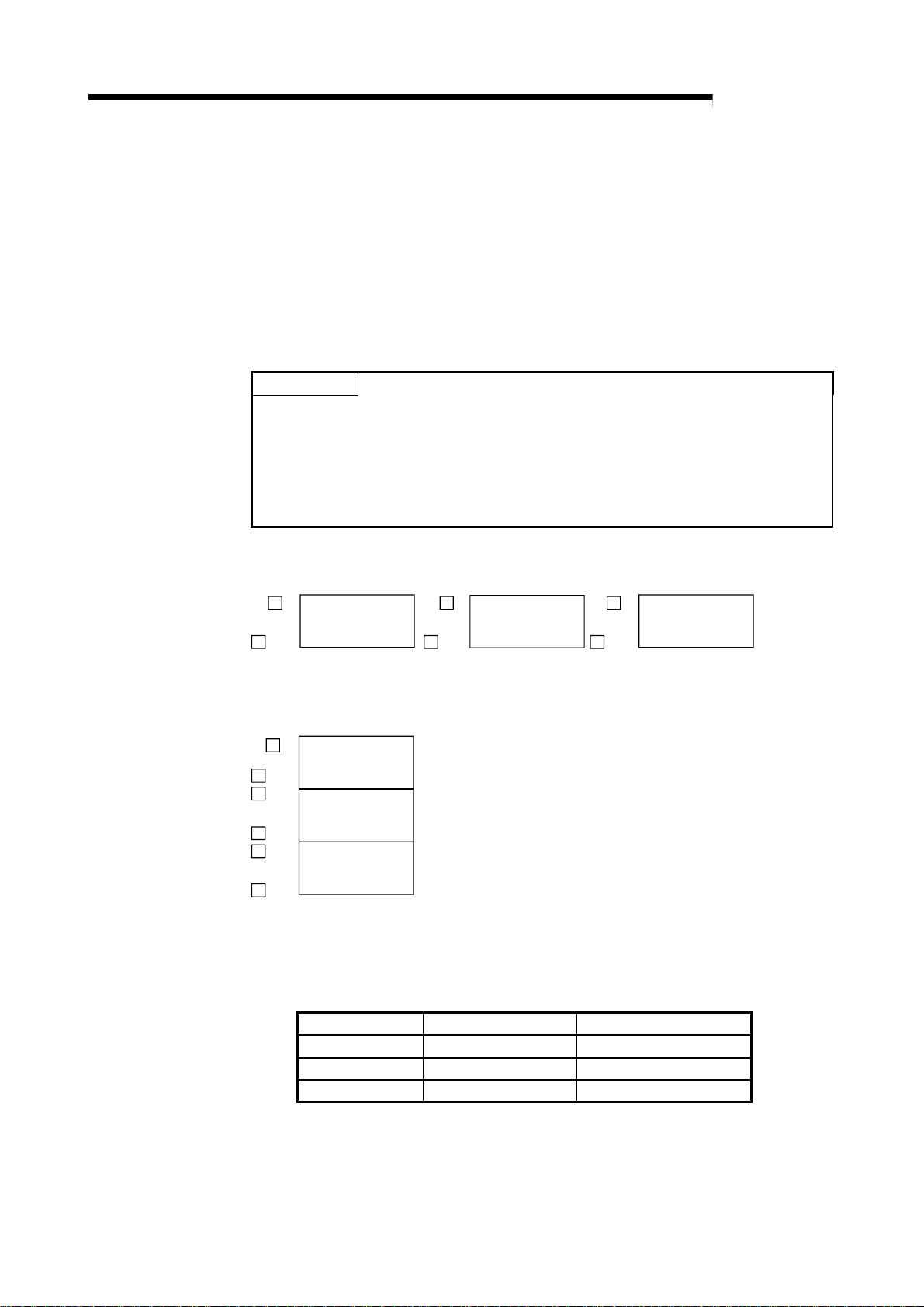
A
5 PRELIMINARY INFORMATION
5.2 Programming Precautions
5.2.1 About bank changing of the A series master module
When using the R2, the master station's automatic update buffer or
transmission/reception buffer is used.
With the A Series master module (AJ61BT11/A1SJ61BT11), the automatic update
buffer and transmission/reception buffer are divided with banks. When accessing these
buffers, the bank must be changed.
POINT
•
When using dedicated commands (RITO, RIFR, RIRD, RIWT, RISEND,
RIRCV), the bank is changed with the dedicated commands, and does not need
to be changed by the user.
•
After changing to bank 1 or bank 2 and then reading or writing, return to bank 0.
The information such as RX, RY, RWw or RWr will not be updated unless the
bank is changed to bank 0.
MELSEC-
A Series master module buffer memory (AJ61BT11/A1SJ61BT11)
Bank 0 Bank 1 Bank 2
0HM 0
Parameter, status
information, etc.
FFF
M FFF
H
M 0
H
Intelligent device
station transmission
M FFF
/reception buffer
H
M
H
Intelligent device
station automatic
M
update buffer
H
Q/QnA Series master module buffer memory
(AJ61QBT11/A1SJ61QBT11/QJ61BT11/QJ61BT11N)
0
M
H
Parameter, status
information, etc.
FFF
M
H
1000
M
H
Intelligent device
station transmission
M
M
M
/reception buffer
1FFF
H
2000
H
2FFF
H
Intelligent device
station automatic
update buffer
(1) Changing the bank
The bank can be changed by turning the master module's Y(n+1)C, Y(n+1)D ON
and OFF.
n indicates the master module's head input/output No.
Y (n+1) C Y (n+1) D Details
OFF OFF Change to bank 0
ON OFF Change to bank 1
OFF ON Change to bank 2
5 - 3
Page 62

A
5 PRELIMINARY INFORMATION
(2) Program
Create the program for changing the bank as shown below.
Refer to section 5.1 for details on the program conditions.
(a) Program for changing to bank 0
MELSEC-
Changeover execution
Changeover execution
Changeover execution
Specify partial
refresh
Specify bank 0
Execute partial
refresh
(b) Program for changing to bank 1
Specify partial
refresh
Specify bank 1
Execute partial
refresh
(c) Program for changing to bank 2
Specify partial
refresh
5 - 4
Specify bank 2
Execute partial
refresh
Page 63
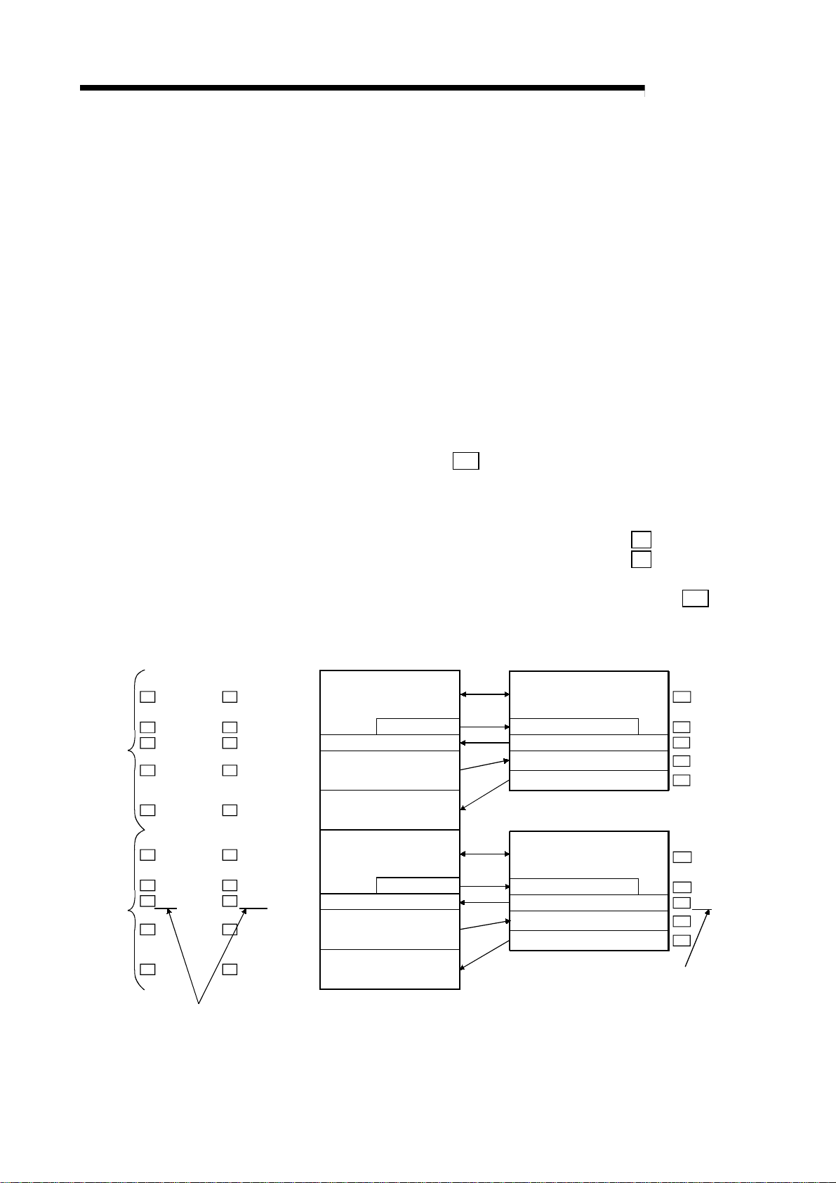
A
5 PRELIMINARY INFORMATION
MELSEC-
5.2.2 About dedicated commands for use of the buffer memory automatic update function
When the buffer memory automatic update function is used, the R2 buffer memory to
be specified differs as described below between when the FROM/TO command is
used and when the dedicated command is used.
(1) When the FROM/TO command is used
Specify the buffer memory address of the master station where the buffer
memory of the R2 to be accessed is assigned.
(2) When the dedicated command is used
Since the station number of the R2 to be accessed can be set, specify the buffer
memory of the R2 directly.
(Example) When automatic update has been set as described below, the contents of
the "status storage area (
1A0H)" of station No. 2 are to be read.
R2
Station 1
Station 2
A series
(Bank 2)
118
M
1A0
M
1C0H to 2BFHM
M
2C0
3C0
4D8
M
560
M
580
0H to 19FHM
H to
H to
H to 3BFH
H to 55FHM
H to
H to
H to 67FHM
Q/QnA series
19F
H
1BF
H
55F
H
57F
H
When the FROM/TO command is used:
Specify the buffer memory address of the master station.
•
When the master station is the A series ............... M 560H of bank 2
•
When the master station is the Q/QnA series ...... M 2560H
When the dedicated command is used:
Specify the station number (2) and buffer memory address (
of the R2.
Master station buffer memory
(Automatic update buffer)
2000H to 219FH
M
M
M
M
M
2118
21A0
21C0H to 22BFHM
22C0
23C0
24D8
2560
2580
H to
H to
H to 23BFHM
H to 255FHM
H to
H to
H to 267FHM
219F
21BF
255F
257F
Initial setting area
H
Status storage area
H
Sending area 2
Receiving area
Initial setting area
H
H
Status storage area
Sending area 2
Sending area 1
Sending area 1
R2 buffer memory (Station 1)
Initial setting area (for 1A0
Sending area 1 (for 88
)
H
Status storage area (for 20
Sending area 2 (for 100
Receiving area (for 100
H
H
R2 buffer memory (Station 2)
Initial setting area (for 1A0
Sending area 1 (for 88
H)
Status storage area (for 20
Sending area 2 (for 100
Receiving area (for 100
H
H
R2
)
H
R2 0H to 19FH
118H to 19F
R2
R2 1A0H to 1BFH
H)
)
R2 200H to 2FF
)
R2 300H to 3FF
R2 0H to 19FH
)
H
118H to 19F
R2
R2 1A0H to 1BFH
H)
)
R2 200H to 2FF
R2 300H to 3FF
)
1A0H)
H
H
H
H
H
H
680
H to
77F
M
2680
M
H
H to
277F
H
Receiving area
When using the FROM/TO commands, specify the buffer
memory address of the master station where the R2 buffer
memory has been assigned.
5 - 5
When using the dedicated commands, specify the
station number and R2 buffer memory address.
Page 64

A
5 PRELIMINARY INFORMATION
5.3 Program basic format
The basic format for creating a program is shown below.
The program is created with the following arrangement.
Refer to section 5.1 for details on the program conditions.
(1) Master station initialization (Refer to section 5.4.)
(Parameter settings, start of data link)
(2) Reading of remote input (RX)
(3) Confirmation of R2 data link state
(4) R2 initialization (Refer to section 5.5)
(5) Transmission of data to external device
(Refer to sections 6.3.1 and 6.4.1.)
MELSEC-
(1) Create a program that instructs CC-Link refreshing and then starts the data link
(2) Create the following program, and read RXn0 to RX(n+1)F into X100 to X11F.
Module error (master station)
Module ready (master station)
Local station data link state (master station)
(6) Reception of data from external device
(Refer to sections 6.3.2 and 6.4.2)
(7) R2 error processing
(8) Writing of remote output (RY)
after the parameters are set. (Refer to section 5.4.)
Changeover to bank 0
Read 'RXn0 to RX(n+1)F'
to 'X100 to X11F'
POINT
When using QCPU (Q mode) or QnACPU, setting automatic refresh parameters
refreshes the contents of the remote input (RX) and remote output (RY)
automatically. Thus, the above program is not required.
5 - 6
Page 65

A
5 PRELIMINARY INFORMATION
(3) Create a program that detects the R2 data link state and establishes an interlock.
MELSEC-
Read R2 data link state
R2 data link normal
Transmission error complete (RXn1)
R2
normal
Required when using
transmission/reception
buffer
Reception error read request (RXn3)
Initialization error complete (RXn5)
EEPROM function error complete (RXn8)
Error reset
Program for R2 error
R2 data link error
(4) Create a program that initializes the R2. (Refer to section 5.5)
(5) Create a program that transmits data to the external device. (Refer to sections
6.3.1 and 6.4.1.)
(6) Create a program that receives data from the external device. (Refer to sections
6.3.2 and 6.4.2.)
(7) Create the following program to process the R2 error (reset the error).
Set the error
occurrence flag
Process program for error
Reset the error
occurrence flag
5 - 7
Error reset
Page 66

A
5 PRELIMINARY INFORMATION
o
(8) Create the following program and write Y100 to Y11F into RYn0 to RY(n+1)F.
Module error (master station)
Module ready (master station)
Local station data link state (master station)
POINT
When using QCPU (Q mode) or QnACPU, setting automatic refresh parameters
refreshes the contents of the remote input (RX) and remote output (RY)
automatically. Thus, the above program is not required.
(a) Using the dedicated commands (RIRD, RIWT, RISEND,
RIRCV)
When the dedicated commands (RIRD, RIWT, RISEND, RIRCV) are used,
RY(n+1)E, RY(n+1)F are used with the dedicated commands, so the user
must make sure that this signal information is not rewritten.
When the QCPU(Q mode) is used, such provisions need not be mode.
MELSEC-
Changeover to bank 0
Write 'Y100 to Y11F' t
'RYn0 to RY(n+1)F'
1) When using ACPU
Changeover to bank 0
2) To set automatic refresh with QnACPU
Read RY new information
Retrieve RY(n+1)E,
RY(n+1)F state
Write to RYn0
to RY(n+1)F
Read RY new information
Retrieve RY(n+1)E,
RY(n+1)F state
5 - 8
Page 67

A
5 PRELIMINARY INFORMATION
5.4 Initializing the master station
Create the following program to initialize (set the parameters, start the data link) the
master station.
Refer to section 5.1 for details on the program conditions.
(Example) No. of connected modules: One module, Connected station: R2 (Station
No. 1, one station occupied)
MELSEC-
(1) Set the No. of
connected modules
(2) Set the station
information
(3) Set the master
station buffer memory
Refresh indication
Start data link with buffer
memory
If normal, reset start
request signal
If error, read parameter state
Reset start request signal
POINT
When setting the information (1) to (3) as parameters when using QCPU (Q mode)
or QnACPU, the above program is not required.
(1) No. of connected modules ( M 1H)
Set the No. of remote I/O stations, remote device stations, intelligent device
stations and local stations connected to the master station. (Including the
reserved stations.)
5 - 9
Page 68

A
5 PRELIMINARY INFORMATION
(2) Station information ( M 20H (1st module) to M 5FH (64th module))
Set the type of remote I/O station, remote device station, intelligent device station
and local station connected to the master station.
This must be set for each module connected.
Station type
No. of occupied
stations
Station No.
MELSEC-
0123456789101112131415
(bit)
1: 1 station occupied
2: 2 stations occupied
3: 3 stations occupied
0: Remote I/O station
1: Remote device station
2: Intelligent device station
4: 4 stations occupied
(Example) To set R2 to station No. 30
2 1 1 E
H
Station No. 30 (1EH)
No. of occupied stations (R2 occupies one station.)
Station type (R2 is an intelligent device station.)
(3) Master station buffer size
Address
80
M
81
M
82
M
∼
CBH
M
CC
M
M
CD
Details
H
Transmission buffer
H
Reception buffer
Automatic update buffer
H
∼
Transmission buffer
H
Reception buffer
Automatic update buffer
H
Default
value
40
40
80
40
40H
80
1(01H) to 64(40H)
H
1st station intelligent
H
device station
H
∼
H
26th station intelligent
device station
H
Set the buffer memory size assignment to be used for transient transmission to
the intelligent device station.
This must be set for each connected device.
Set so that the total of the transmission buffer, reception buffer and automatic
update buffer is within the range of 80
H to 1000H.
(a) Transmission buffer, reception buffer
Set this when communicating with R2 using the transmission/reception
buffer.
Designate as the transmission/reception data size plus seven words.
5 - 10
Page 69

A
5 PRELIMINARY INFORMATION
(b) Automatic update buffer
Set this when communicating with R2 using the buffer memory automatic
update function.
When using the R2 automatic update area with the default value, "600
required.
Even if the automatic update area size is set to the minimum, the default
setting area amount (1A0
ensured, so set "1C0
Refer to section 5.6.2 for details on the automatic update area.
MELSEC-
H " is
H) + the status storage area amount (20H) must be
H + transmission/reception size" or more.
5 - 11
Page 70

A
5 PRELIMINARY INFORMATION
5.5 Initializing the R2
The methods for initializing the R2 are described below.
5.5.1 Using the buffer memory automatic update function
Initialization when using the buffer memory automatic update function changes the
contents of
R2
The values of the initialization area (
0H
to 19F
H.
0H
R2
operation.
The transmission/reception area address, size, range of buffer memory to be
automatically updated and the parameters, etc., can be set.
(1) Before initializing
1) Secure the automatic update buffer size (1C0H or more) by initializing the
master station. (To write
2) Set the R2 mode setting switch to "1" (automatic update function enabled).
0H to 1BFH into the master station)
R2
to 19F
MELSEC-
H) can be changed by using this
(2) Flow of process
Programmable controller CPU Master station
Remote
input (RX)
Bit device
1) Initial data read request ON
5) Initial data read request OFF
Remote
output (RY)
Automatic
update
buffer
Word
device
9) Initialization request ON
12) Initialization request OFF
8) Initialization data
Steps 1), 5), 8), 9) and 12) are carried out
with the sequence program.
2) Remote station ready OFF
4) Initial data read complete ON
6) Initial data read complete OFF
7) Remote station ready ON
11) Initialization normal/error complete ON
13) Initialization normal/error complete OFF
3) R2 default value
10) Initialization data
Steps 2), 3), 4), 6), 7), 10) and 13)
are carried out by R2.
R2
Remote
input (RX)
Remote
output (RY)
Buffer
memory
(initialization
area)
5 - 12
Page 71

A
5 PRELIMINARY INFORMATION
(3) Timing chart
MELSEC-
Initial data read request signal
(RY(n+1)9)
Initial data read complete
signal (RX(n+1)9)
Remote station READY
(RX(n+1)B)
Initialization request signal
(RYn4)
Initialization normal/error
complete signal (RXn4/RXn5)
Master station automatic
update buffer
R2 initialization area
1)
5)
2)
4)
3)
3)
6)
7)
8)
9)
Carried out with sequence program
Carried out by R2
12)
10)
13)
11)
No. Details Control side
1) The initial data read request signal (RY(n+1)9) turns ON. Program
2) The remote station READY (RX(n+1)B) turns OFF. R2
R2
The initialization area (
3)
the master station's automatic update buffer.
0H to 19FH) and status storage area (R2 1A0H to 1BFH) are stored in
R2
4) The initial data read complete signal (RX(n+1)9) turns ON. R2
5) The initial data read request signal (RY(n+1)9) turns OFF. Program
6) The initial data read complete signal (RX(n+1)9) turns OFF. R2
7) The remote station READY (RX(n+1)B) turns ON. R2
8) The values to be changed are written to the master station's automatic update buffer. Program
9) The initialization request signal (RYn4) turns ON. Program
The contents of the master station's automatic update buffer are stored in the initialization area
10)
R2
(
0H to 19FH).
R2
11) The initialization normal/error complete signal (RXn4/RXn5) turns ON. R2
12) The initialization request signal (RYn4) turns OFF. Program
13) The initialization normal/error complete signal (RXn4/RXn5) turns OFF. R2
POINT
If the R2 initialization is completed with an error, remove the cause of the error, and
repeat the initialization request until the process ends normally.
R2 will not accept other requests until the initialization is completed normally.
(If an initialization error occurs, the remote station READY signal (RX(n+1)B) will
turn OFF.)
5 - 13
Page 72

A
5 PRELIMINARY INFORMATION
t
c
(4) Program
Refer to section 5.1 for details on the program conditions.
Master station initialization (parameter setting, data link setting) (Refer to section 5.4.)
Reading of remote input (RX) (Refer to section 5.3 (2).)
Confirmation of R2 data link status (Refer to section 5.3 (3).)
R2 normal
Write initialization data to automatic update buffer (Refer to section 5.6.)
MELSEC-
Set initial data
read request
Reset initial data
read request
Initial data read
complete
Set initialization data
write complete flag
Set initialization request
Reset initialization reques
Set the error
occurrence flag
Initialization complete
Transmission of data to external device (Refer to section 6.3.1.)
Receiption of data from external device (Refer to section 6.3.2.)
R2 error processing (Refer to section 5.3 (7).)
Writing of remote output (RY) (Refer to section 5.3 (8).)
POINT
Create the following interlock circuit so that the initialization request is made after all
request signals (RY) are turned OFF.
OS
reception
buffer clear
request
(RYn6)
EEPROM
function
request
(RYn7)
Initialization
request
(RY(n+1)9)
Error reset
request
(RY(n+1)A)
SET (RYn4)
Initialization
ommand
Transmission request
(RYn0)
Transmission cancel
request
(RYn1)
Reception
read output
complete
(RYn2)
Forced
reception
complete
request
(RYn3)
If initialization is carried out while RX or RY is ON, the current process will be canceled.
Start initialization after turning all RY, other than RYn4, OFF.
5 - 14
Page 73

A
5 PRELIMINARY INFORMATION
5.5.2 Using the transmission/reception buffer
Initialization using the transmission/reception buffer changes the contents of the R2
buffer memory using the transmission/reception buffer.
By using this operation, the transmission/reception area address and size, the range of
the buffer memory to be automatically updated, and the parameters, etc., can be
changed from the default values.
(1) Before initializing
1) Secure the transmission/reception buffer size by initializing the master
station.
Transmission buffer: Secure the transmission data size + seven words
Reception buffer: Secure the reception data size + seven words
2) Set the R2 mode setting switch to "0" (no automatic update function)
(2) Flow of process
MELSEC-
Programmable controller CPU
Bit device
Word device
2) Intelligent device station access
request ON
6) Intelligent device station access
request OFF
8) Initialization request ON
10) Initialization request OFF
1) Control data + initialization data
Steps 1), 2), 6), 8) and 10) are carried out
with the sequence program.
Master station
Remote
input (RX)
Remote
output (RY)
Transmission
buffer
Reception
buffer
5) Intelligent device station access
complete ON
7) Intelligent device station access
complete OFF
9) Initialization normal/error complete ON
11) Initialization normal/error complete OFF
3) Initialization data
4) Control data
Steps 3), 4), 5), 7), 9) and 11) are carried out by R2.
∗ When using the RIWT (RISEND) command,
the steps 2) to 7) are carried out automatically.
Remote
input (RX)
Remote
output (RY)
Buffer
memory
POINT
(1) Steps 1) to 7) are carried out for one write operation.
If writing is to be carried out multiple times because the addresses of the
buffer memories to be written are separated, etc., carry out the steps for each
write operation.
(2) Steps 8) to 11) (initialization) must be carried out when changing
112
H.
Initialization is not required to change the other buffer memories.
R2
R2
0H to
5 - 15
Page 74

A
5 PRELIMINARY INFORMATION
(3) Timing chart
Remote station read signal
(RX(n+1)B)
Intelligent device station access
request signal (RY(n+1)E)
Intelligent device station access
complete signal (RX(n+1)E)
Initialization request signal
(RYn4)
Initialization normal/error
complete signal (RXn4/RXn5)
Programmable controller CPU
word device
Master station
transmission buffer
Master station
reception buffer
1)
MELSEC-
6)
2)
3)
1)
5)
4)
7)
8)
10)
9)
11)
R2 buffer memory
One write operation
Required to change 0H to 112
Carried out with sequence program
Carried out by R2
R2
H
No. Details Control side
The value of buffer memory to be changed and control data is written to master station's
1)
transmission buffer.
Program
2) The intelligent device station access request signal (RY(n+1)E) turns ON. Program
3) The contents of the master station transmission buffer are stored in the R2 buffer memory. R2
4) The control data is stored in the master station reception buffer. R2
5) The intelligent device station access complete signal (RX(n+1)E) turns ON. R2
6) The intelligent device station access request signal (RY(n+1)E) turns OFF. Program
7) The intelligent device station access complete signal (RX(n+1)E) turns OFF. R2
8) The initialization request signal (RYn4) turns ON. Program
Initialization is carried out by R2, and when completed, the initialization normal signal (RXn4) or
9)
error complete signal (RXn5) turns ON.
R2
10) The initialization request signal (RYn4) turns OFF. Program
11) The signal turned ON in step 9) turns OFF. R2
POINT
If the R2 initialization is completed with an error, remove the cause of the error, and
repeat the initialization request until the process ends normally.
R2 will not accept other requests until the initialization is completed normally.
(If an initialization error occurs, the remote station READY signal (RX(n+1)B) will
turn OFF.)
5 - 16
Page 75

A
5 PRELIMINARY INFORMATION
(4) Program
Refer to section 5.7.4 for details on writing the data using the
transmission/reception buffer.
Refer to section 5.1 for details on the program conditions.
Master station initialization (parameter setting, data link setting) (Refer to section 5.4.)
Reading of remote input (RX) (Refer to section 5.3 (2).)
Confirmation of R2 data link status (Refer to section 5.3 (3).)
MELSEC-
R2 normal
Write initialization data to R2 (Refer to section 5.7.4.)
Writing to R2 completed
Transmission of data to external device (Refer to section 6.4.1.)
Receiption of data from external device (Refer to section 6.4.2.)
R2 error processing (Refer to section 5.3 (7).)
Writing of remote output (RY) (Refer to section 5.3 (8).)
Set initialization data
write complete flag
Set initialization request
(RYn4)
Reset initialization request
(RYn4)
Set the error
occurrence flag
Initialization complete
POINT
Create the following interlock circuit so that the initialization request is made after all
request signals (RY) are turned OFF.
Forced
reception
complete
request
(RYn3)
Initialization
command
Transmission request
(RYn0)
Transmission canc el
request
(RYn1)
Reception
read output
complet e
(RYn2)
If initialization is carried out while RX or RY is ON, the current process will be canceled.
Start initialization after turning all RY, other than RYn4, OFF.
5 - 17
OS
reception
buffer clear
request
(RYn6)
EEPROM
function
request
(RYn7)
Initialization
request
(RY(n+1)9 )
Error reset
request
(RY(n+1) A)
SET (RYn4)
Page 76

A
5 PRELIMINARY INFORMATION
MELSEC-
5.6 Reading and writing the buffer memory (using the buffer memory automatic update function)
The methods for reading and writing the R2 buffer memory using the buffer memory
automatic update function is described in this section.
When the buffer memory automatic update function is used, data can be read and
written using the FROM/TO command, so the sequence program can be simplified.
5.6.1 Outline
With the buffer memory automatic update function, if a cause of data communication
between the R2 buffer memory automatic update area and master station automatic
update buffer is generated, the data is automatically exchanged, and the data in the
corresponding area of each station is updated.
Refer to section 5.6.2 for details on each area and the update timing.
•
Reading : The master station buffer memory corresponding to the buffer memory
to be read is read out with the FROM/RIFR command.
•
Writing : Data is written to the master station buffer memory corresponding to
the buffer memory to be written in using the TO/RITO command.
Programmable controller CPU
TO(RITO)
FROM(RIFR)
1st station's
automatic
update
buffer
Master station
Buffer memory
(automatic update area)
Status storage area
Transmission area
Monitor transmission area
.....
2nd station automatic
update area
.....
Automatic update
R2 (1st station)
Buffer memory
Status storage area
Transmission area
.....
Monitor transmission area
If a cause of automatic update, explained in section 5.6.2,
occurs, the area is automatically updated.
(1) Changing the bank when using the A Series master module
When using the A Series master module (AJ61BT11/A1SJ61BT11), the master
station's automatic update buffer will be "bank 2".
Thus, create the program so that the bank is changed to "bank 2" when reading
to or writing from the automatic update buffer, and so that "bank 0" is returned to
after the reading/writing is completed.
When using the RITO/RIFR commands dedicated for the AnSHCPU, the bank
will not be changed automatically by the commands. Thus, the bank must be
changed by the user.
Refer to section 5.2 for details on changing the bank.
(2) Setting the timeout
By setting the following buffer memory in the R2, a timeout can be set for
exchanging data between the R2 and master station when using the buffer
memory automatic update function.
(a) Transient timeout designation area (
0: 5 seconds 1 to 360: designated time (seconds)
5 - 18
R2
105H)
Page 77

A
5 PRELIMINARY INFORMATION
5.6.2 Understanding the roles of each area
When using the buffer memory automatic update function, the information of each area
in the automatic update area designation (
The timing for carrying out automatic update in each area is determined by the R2.
The application of each area differs according to the timing.
(1) Role of each area
10H to 33H) is important.
R2
MELSEC-
(a) Status storage area (
10H to 13H)
R2
This area is used to store the error codes and transmission/reception data
information in the master station.
This area is required for initialization, so use it with the default settings.
1) Update timing (Update direction: R2 to master station)
The data in the R2 buffer memory is stored in the master station at the
following timing.
•
Just before the R2 turns the transmission normal (error) complete
signal (RXn0/RXn1) ON.
•
Just before the R2 turns the reception normal (error) read request
signal (RXn2/RXn3) ON.
•
Just before the R2 turns the initialization normal (error) complete
signal (RXn4/RXn5) ON.
•
Just before the R2 turns the EEPROM function normal (error)
complete signal (RXn7/RXn8) ON.
•
Just before the R2 detects that the error reset request signal
(RY(n+1)A) is ON.
•
Just after the R2 detects an error when transmitting data with the
monitor transmission function.
•
Just before the R2 turns the initial data read complete signal
(RX(n+1)9) ON.
Master station
2) Error code, transmission/
reception data information
Transmitted at timing set
in status storage area!
5 - 19
1) Transmission
error complete!
R2
Page 78
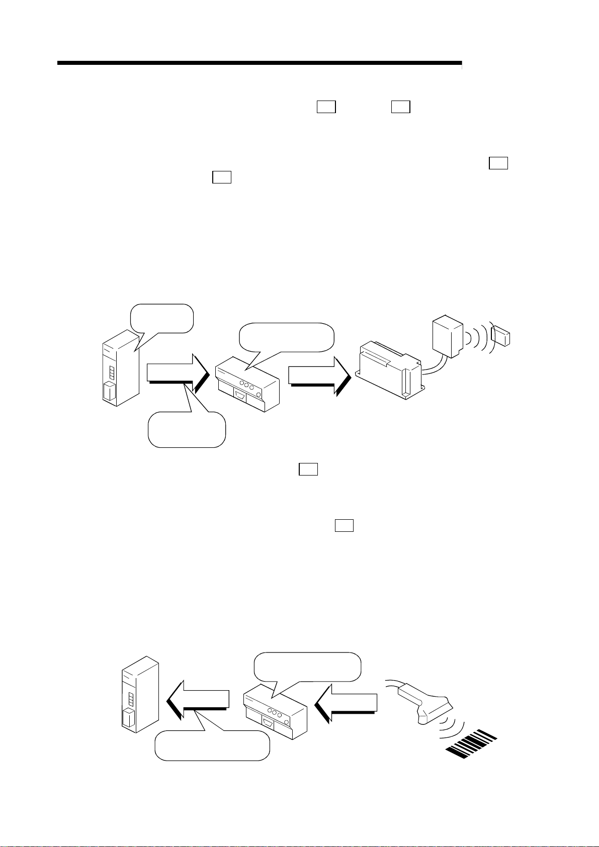
A
5 PRELIMINARY INFORMATION
MELSEC-
1) Transmission
request ON!
3) Transmission
data
(b) Transmission area (
14H to 17H, R2 18H to 1BH)
R2
This area is used to store the data transmitted to the external device from
the master station to the R2.
When using a reading dedicated device, such as a barcode reader, the
data does not need to be transmitted, so the transmission size (
18H) can be set to "0".
R2
The default transmission size is 200
H, so the transmission side can be
reduced by setting it according to the No. of words being used.
1) Update timing (Update direction: Master station to R2)
The master station data is stored in the R2 buffer memory at the
following timing.
•
Just after the R2 detects that the transmission request signal
(RYn0) has turned from OFF to ON.
2) Transmission request
ON confirmed!
3) Transmission
data
R2
14H,
Master station
Transmit after R2
detects transmission request ON!
(c) Reception area (
This area is used to store the data received by the R2 from an external
device to the master station.
When writing with an ID controller, etc., and there is no need to receive
data, the transmission size (
The default transmission size is 200
reduced by setting it according to the No. of words being used.
1) Update timing (Update direction: R2 to Master station)
2) Reception data
R2
1CH to 1FH)
R2
External device such as ID controller
1CH ) can be set to "0".
R2
H, so the transmission side can be
The master station data is stored in the R2 buffer memory at the
following timing.
•
Just before the R2 turns ON the reception normal read request
signal (RXn2)/reception error read request signal (RXn3).
3) Reception normal (error)
read request ON!
1) Reception data
Master station
Transmit just before reception
normal (error) read turns ON!
R2
5 - 20
External device such
as ID controller or
barcode reader
Page 79
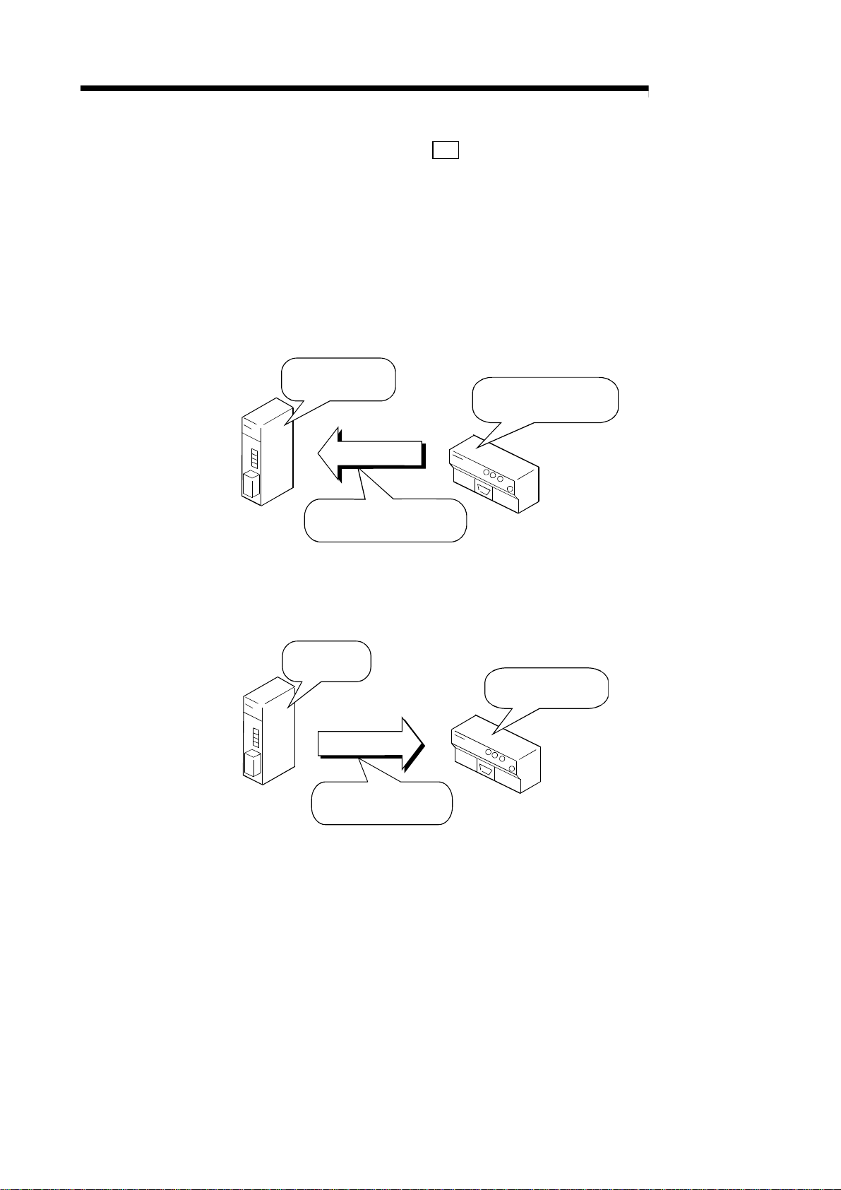
A
5 PRELIMINARY INFORMATION
MELSEC-
(d) Initialization area (
This area is used to store the initialization parameters in the master station,
or to read them from the master station.
This area is required during initialization, so use the default values.
1) Update timing
The data is updated at the following timing.
•
1) Initial data read
request ON!
3) Initialization data
Master station
Transmit immediately after
R2 detects initial data read
request ON!
20H to 23H)
R2
Immediately after the R2 detects that the initial data read request
signal (RY(n+1)9) has turned from OFF to ON.
(Update direction: R2 to master station)
2) Initial data read request
ON confirmed!
R2
1) Initialization
request ON!
Master station
•
Immediately after R2 detects that the initialization request signal
(RYn4) has turned from OFF to ON.
(Update direction: master station to R2)
2) Initialization request
ON confirmed!
3) Initialization data
Transmit after R2 detects
initialization request ON!
R2
5 - 21
Page 80

A
5 PRELIMINARY INFORMATION
MELSEC-
(e) EEPROM function area (
This area is used to initialize the EEPROM, and to register, call and delete
the user registration frames.
When the EEPROM is not to be initialized, or when the user registration
frames are not to be registered, called or deleted, the transmission size
(
24H) can be set to "0".
R2
1) Update timing (Update direction: Master station to R2)
The master station data is stored in the R2 buffer memory at the
following timing.
•
Immediately after the R2 detects that the EEPROM function
request signal (RYn7) has turned from OFF to ON.
1) EEPROM function
request ON!
3) User registration frame
data, etc.
Master station
Transmit after R2 detects
EEPROM function request ON!
24H to 27H)
R2
2) EEPROM function
request ON confirmed!
R2
Master station
(f) User registration frame area (
28H to 2BH)
R2
This area is used to store the user registration frame data after the
EEPROM has been initialized, or the user registration frames have been
registered, called or deleted with the EEPROM function area.
If the user registration frame state is not to be confirmed, the transmission
size (
28H) can be set to "0".
R2
1) Update timing (Update direction: R2 to master station)
The R2 buffer memory data is stored in the master station at the
following timing.
•
Just before the R2 turns the EEPROM function normal complete
signal (RXn7)/EEPROM function error complete signal (RXn8) ON.
2) EEPROM function normal
(error) complete ON!
1) User registration frame
data
Transmit just before EEPROM
function normal (error) complete
turns ON!
R2
5 - 22
Page 81

A
5 PRELIMINARY INFORMATION
MELSEC-
Master station
(g) Monitor transmission area (
This area is used to store the data transmitted from the external device
using the monitor transmission function, from the master station to R2.
When not using the monitor transmission function, the transmission size
(
R2
The default transmission size is 200
reduced by setting it according to the No. of words being used.
1) Update timing (Update direction: Master station to R2)
2) Transmission
data
Transmit after R2
detects monitor
condition establishment!
2CH to 2FH, R2 30H to 33H)
R2
2CH, R2 30H) can be set to "0".
H, so the transmission size can be
The master station data is stored in the R2 buffer memory at the
following timing.
•
Just after the conditions are established in the monitor transmission
function.
1) Monitor conditions
established!
3) Transmission
data
R2
External device, such as ID controller
5 - 23
Page 82

A
5 PRELIMINARY INFORMATION
(2) Buffer memory for setting each area
The buffer memories used to set each area's information (transmission size,
head address, master side head offset address) are shown below.
Area name
Status storage area
Transmission
area
Reception area
Initialization area
EEPROM function
area
User registration
frame area
Monitor transmission area
Transmission
1)
2)
1)
2)
MELSEC-
(a) (b) (c) (d)
R2
R2
R2
R2
R2
R2
R2
R2
R2
size
10H
14H
18H
1CH
20H
24H
28H
2CH
30H
R2 side head
address
R2
11H
R2
15H
R2
19H
R2
1DH
R2
21H
R2
25H
R2
29H
R2
2DH
R2
31H
Fixed value
R2
12H
R2
16H
R2
1AH
R2
1EH
R2
22H
R2
26H
R2
2AH
R2
2EH
R2
32H
Master station side
offset address
R2
R2
R2
R2
R2
R2
R2
R2
R2
13H
17H
1BH
1FH
23H
27H
2BH
2FH
33H
Buffer memory
address
1st station automatic
update buffer (600
H
(a) Transmission size
Designate the size (No. of addresses) to be automatically updated.
0 : No designation
Other than 0 : Transmission size (No. of words)
(b) R2 side head address
Designate the head address of the R2 side data range to be automatically
updated.
(c) Fixed value
Designate 4004
H.
Note that the default value is 4004
(d) Master station side offset address
Designate the head address of the master station side data range to be
automatically updated.
Designate using 0
H for the head address of the automatic update buffer
assigned for R2 in the master station automatic update buffer.
(Example) When R2 is the 2nd station
Master station 2nd station R2
0
H
M
)
H, so this does not need to be changed.
0
H
R2
Initialization area
Status storage area
R2
R2
19F
1A0
H
H
2nd station automatic
update buffer (600
)
H
0
19F
1A0
H
H
H
Master station side offset address
600
H
M
BFF
M
Initialization area
Status storage area
H
5 - 24
Page 83

A
5 PRELIMINARY INFORMATION
×
(3) Default size of each area
When totaled the default size of each area is 600H.
The size of the master station automatic update area is 1000
default setting, only two R2 modules can be connected.
Users using three or more R2 modules must reduce and delete the areas not
being used to reduce the automatic update size (transmission size).
MELSEC-
H, so if used with the
Master station automatic update
buffer (Offset address)
0HM
Initialization area
118
H
M
M
M
M
M
M
Transmission, monitor transmission area 1)
1A0
1C0
1C7
1F0
200
H
H
H
H
H
Status storage area
EEPROM function area
User registration frame area
Blank
Transmission, monitor
Update at timing
for each area.
transmission area 2)
400
H
M
Reception area
600
H
M
R2 buffer memory
Initialization area
Transmission, monitor transmission area 1)
Status storage area
EEPROM function area
User registration frame area
Blank
Transmission, monitor
transmission area 2)
Reception area
R2 0
R2 118
R2 1A0
R2 1C0
R2 1C7
R2 1F0
R2 200
R2 400
R2 600
H
H
H
H
H
H
H
H
H
(a) Relation of No. of modules and each area size
As the No. of R2 modules being used increases, the size of the areas other
than the initialization area and status storage area must be reduced or else
the master station buffer memory (1000
H) will be exceeded.
The sizes of the areas that can be set are described below.
1) When connecting two R2 modules
Master station automatic update buffer (1000H) –
(Initialization (1A0
H) + Status storage area (20H))
The size of the areas, other than the initialization area, which can be
used by the two R2 modules will be C80
H.
The size per module will be 640H.
2 = C80H
Master station (1000Hworth)
Initialization, status storage area (1C0H worth)
1st station automatic
update buffer
2nd station automatic
update buffer
Initialization, status storage area (1C0H worth)
Other area
Other area
Total C80H
(640
per module)
H
5 - 25
Page 84

A
5 PRELIMINARY INFORMATION
×
4
×
r
2
r
4
2) When connecting four R2 modules
Master station automatic update buffer (1000H) –
(Initialization (1A0
The size of the areas, other than the initialization area, which can be
used by the four R2 modules will be 900
The size per module will be 240H.
Initialization, status storage area (1C0H worth)
1st station automatic
update buffer
Initialization, status storage area (1C0H worth)
2nd station automatic
update buffer
Initialization, status storage area (1C0H worth)
3rd station automatic
update buffer
H) + Status storage area (20H))
Master station (1000H worth)
Other area
Other area
Other area
H.
Total 900
H
per module)
(240
H
MELSEC-
4 = 900H
th station automatic
update buffer
1st station automatic
update buffe
nd station automatic
update buffe
3rd station automatic
update buffer
th station automatic
update buffer
5th station automatic
update buffer
6th station automatic
update buffer
7th station automatic
update buffer
8th station automatic
update buffer
Initialization, status storage area (1C0H worth)
Other area
3) When connecting eight R2 modules
Master station automatic update buffer (1000H) –
(Initialization (1A0
The size of the areas, other than the initialization area, which can be
used by the eight R2 modules will be 200
The size per module will be 40H.
Master station (1000H worth)
Initialization, status storage area (1C0H worth)
Other area
Initialization, status storage area (1C0H worth)
Other area
Initialization, status storage area (1C0H worth)
Other area
Initialization, status storage area (1C0H worth)
Other area
Initialization, status storage area (1C0H worth)
Other area
Initialization, status storage area (1C0H worth)
Other area
Initialization, status storage area (1C0H worth)
Other area
Initialization, status storage area (1C0H worth)
Other area
H) + Status storage area (20H))
H.
Total 200H
(40
per module)
H
8 = 200H
5 - 26
Page 85

A
5 PRELIMINARY INFORMATION
(b) An example for reducing each area is shown below.
(Example) To transmit and receive 20-word data to connect eight R2
MELSEC-
modules
Area name
Status storage area
Transmission area 1)
Transmission area 2)
Reception area
Initialization area
EEPROM function area
User registration frame area
Monitor transmission area 1)
Monitor transmission area 2)
Master station automatic update buffer
(offset address)
0
M
H
Initialization area (1A0
1A0
M
H
M
1C0
1D4
M
M
1E7
Status storage area (20H worth)
H
Transmission area 2) (14
H
Reception area (14
H
Reduce area to 1E8
Transmission size R2 side head address
Address Value Address Value Address Value
R2
R2
R2
R2
R2
R2
R2
R2
R2
worth)
H
Transmission area 1)
worth)
H
worth)
H
!
H
10H
14H
18H
1CH
20H
24H
28H
2CH
30H
Default value
Default value
14H
14H
Default value
0H
0H
0H
0H
Master station side offset
R2
11H
R2
15H
R2
19H
R2
1DH
R2
21H
Default value
R2
25H
R2
29H
R2
2DH
R2
31H
R2 buffer memory
Initialization area
Transmission area 1)
Status storage area
Blank (Area not updated automatically)
Transmission area 2) area
Blank (Area not updated automatically)
Reception area
Blank (Area not updated automatically)
R2
R2
R2
R2
R2
R2
R2
R2
R2
address
13H
17H
1BH
1FH
23H
27H
2BH
2FH
33H
R2 0
R2 19F
R2 1BF
R2 200
R2 213
R2 400
R2 413
Default value
1C0H
1D4H
Default value
H
H
H
H
H
H
H
5 - 27
Page 86

A
5 PRELIMINARY INFORMATION
MELSEC-
5.7 Reading and writing the buffer memory (using the transmission/reception buffer)
The method for reading and writing the R2 buffer memory using the
transmission/reception buffer is described below.
When the transmission/reception buffer is used, the required size only can be
adequately transmitted so excess data is not transmitted.
This allows the transmission path efficiency to be improved.
5.7.1 Outline
When reading and writing the R2 buffer memory using the transmission/reception
buffer, reading and writing are carried out using the intelligent device station access
request signal (RY(n+1)E) and the intelligent device station access complete signal
(RX(n+1)E).
The master station buffer memory uses the transmission/reception buffer.
Programmable controller CPU Master station
Buffer memory
(Transmission/reception area)
TO(RIWT,RISEND)
FROM(RIRD,RIRCV)
1) 2)
Transmission area
Reception area
2nd station transmission/
reception area
...
1st station transmission/reception area
(1) Data (control data + transmission data) is stored in the master station
transmission area.
(2) When the intelligent device station access request signal (RY(n+1)E) turns ON,
the data stored in the transmission area is stored in the R2.
(3) When the intelligent device station access complete signal (RX(n+1)E) turns ON,
the response is stored in the master station reception area.
(4) The data is read from the master station reception area.
POINT
When the dedicated commands RIWT/RIRD/RISEND/RIRCV are used, the
intelligent device station access request signal (RY(n+1)E) and intelligent device
station access complete signal (RX(n+1)E) are controlled by the dedicated
commands, so the user does not need to establish an interlock.
R2 (1st station)
Buffer memory
3)4)
5 - 28
Page 87

A
5 PRELIMINARY INFORMATION
(1) Changing the bank when using the A Series master module
When using the A series master module (AJ61BT11/A1SJ61BT11), the master
station's automatic transmission/reception buffer will be "bank 1".
Thus, create a program that changes to "bank 1"when reading or writing to the
transmission/reception buffer, and returns to "bank 0" when the reading/writing is
completed.
When using the dedicated commands RIWT/RIRD/RISEND/RIRCV, the bank will
be changed automatically by the dedicated commands, so the user does not
need to change the bank.
Refer to section 5.2 for details on changing the bank.
5.7.2 Control data
When transmitting data using the transmission/reception buffer, the control data must
be added to the transmission data before transmitting.
When receiving data, the control data will be added to the head of the reception data.
The following examples are explained in this section for the control data.
MELSEC-
•
Transmission buffer address (200H worth)
When using A Series master station : Bank 1
When using Q/QnA Series master station : M 1000H to 11FFH
•
Reception buffer address (200H worth)
When using A Series master station : Bank 1
When using Q/QnA Series master station : M 1200H to 13FFH
M 0H to 1FFH
M 200H to 3FFH
POINT
Refer to the following manuals for details on the control data when using the
dedicated commands (RIWT/RISEND/RIRD/RIRCV).
•
When using ACPU/QCPU-A (A mode) : AnSHCPU/AnACPU/AnUCPU
Programming Manual (Dedicated
Commands)
•
When using QnACPU : QnACPU Programming Manual (Special Function
Module)
•
When using QCPU (Q mode) : QJ61BT11N/QJ61BT11 User's Manual
5 - 29
Page 88

A
5 PRELIMINARY INFORMATION
(1) When using the RIWT command
This is used only when writing to the R2-designated buffer memory.
When using the RIWT command, the master station buffer memory will be used
as the transmission buffer for the control data and write data.
The complete status will be stored in the reception buffer.
(Example) Writing in the reception complete data size and reception timeout
MELSEC-
time
One word
each
Programmable controller CPU
Refer to control data (a)
Reception complete data size designation
Write
data
Reception timeout time designation
Q/QnA Series A Series
1200
M
1201
M
(a) Control data
Address
H
H
Bank 1
Bank 1
Master module
(Transmission buffer)
Address
1000
to 11FF
M
H
H
of Q/QnA Series
M
0H to 1FF
of A Series bank 1
(Reception buffer)
+
200
M
+
201
M
Complete status
H
Station No., request code
H
Address
R2 111
H
R2 112
Reception complete data size designation
H
area
Reception timeout time designation area
H
R2
Note that the control data differs between the QCPU (Q mode)/QnACPU
and ACPU/QCPU-A (A mode) as shown below.
When using ACPU/QCPU-A (A mode) When using QCPU (Q mode)/QnACPU
Control data Control data
Complete status Complete status
One word
each
Access code, attribute Access code, attribute
One word
each
Buffer memory address
Station No.No. of write points (words)
Buffer memory address
No. of write points (words)
5 - 30
Page 89

A
5 PRELIMINARY INFORMATION
(2) When using RISEND command
This is used to write to a R2-designated buffer memory with executing
handshake automatically between the master station and R2.
When using the RISEND command, the master station buffer memory will be
used as the transmission buffer for the control data and write data.
The complete status will be stored in the reception buffer.
(Example) Writing and transmitting 2-word transmission data to master station
MELSEC-
One word
each
Programmable controller CPU
Refer to control data (a)
Reception data size
Write data
Transmission data 1
Transmission data 2
Refer to interlock signal (b)
Q/QnA Series A Series
Master module
(Transmission buffer)
Address
to 11FF
M
1000
H
H
of Q/QnA Series
M
0H to 1FF
of A Series bank 1
Address
(Reception buffer)
1200
M
H
1201
M
H
Bank 1
Bank 1
+
200
M
+
201
M
Complete status
H
Station No., request code
H
Address
R2 200
H
H
R2 201
R2 202
H
H
Transmission
area
R2
Transmission data size
Transmission data 1
Transmission data 2
Transmission request
signal (RYn0)
Transmission normal
complete signal (RXn0)
Transmission error
complete signal (RXn1)
RISEND command
execution
Writing to
buffer memory
At transmission
normal completion
At transmission
error completion
RISEND command
execution complete
5 - 31
Page 90

A
5 PRELIMINARY INFORMATION
(a) Control data
Note that the control data differs between the QCPU (Q mode)/QnACPU
and ACPU/QCPU-A (A mode) as shown below.
When using ACPU/QCPU-A (A mode) When using QCPU (Q mode)/QnACPU
Control data Control data
Complete status Complete status
No. of write points (word)
One word
each
Fixed to 0004
Error confirmation
Buffer memory address
(b) Interlock signal
Note that the interlock signal differs between the QCPU (Q mode)/QnACPU
and ACPU/QCPU-A (A mode) as shown below.
MELSEC-
Station No.
H
One word
each
Access code, attribute
Buffer memory address
No. of write points (word)
One word
each
When using ACPU/QCPU-A (A mode)
Interlock signal Interlock signal
b15 b8b7 b0
RX (Complete device)
to
RY (Request device)
RWr (Error code storage device)
to to
One word
each
When using QCPU (Q mode)/QnACPU
b15 b8b7 b0
0
RWr
(Error code
storage device)
Complete mode
to
RY (Request device)
RX (Complete device)
5 - 32
Page 91

A
5 PRELIMINARY INFORMATION
(3) When using the TO command (Not available when using QCPU (Q
mode))
This is used only when writing to the R2-designated buffer memory.
When using the TO command, the master station buffer memory will be used as
the transmission buffer for the control data and write data.
The complete status will be stored in the reception buffer.
The data designated with the transmission buffer is written to the R2 buffer
memory using the intelligent device station access request (complete) signal
(RY(n+1)E and RX(n+1)E).
(Example) Writing in the reception complete data size and reception timeout
MELSEC-
time
Address
QnA Series A Series
M
1000
H
1001
M
H
1002
M
H
1003
M
H
M
1004
H
1005
M
H
1006
M
H
1007
M
H
1008
M
H
1009
M
H
M
1200
H
Bank 1
1201
M
H
Bank 2
Bank 1
Bank 1
Bank 1
Bank 1
Bank 1
Bank 1
Bank 1
Bank 1
Bank 1
Bank 1
+
+
+
+
+
+
+
+
+
+
+
M
+
M
Master module
(Transmission buffer)
M
0
H
1
M
H
2
M
H
Control
M
3
H
data
4
M
H
5
M
H
M
6
H
M
7
H
Write
M
M
data
8
H
9
H
Dummy area
Station No., request code
Transmission buffer write
data size (byte)
Quantity
Access code, attribute
Buffer memory address
No. of write points (word)
Reception complete data
size designation
Reception timeout time
designation
(Reception buffer)
200
H
Complete status
1
*
Address
R2 111
H
R2 112
H
2
*
R2
Reception complete data
size designation area
Reception timeout time
designation area
Control
201
H
data
Station No., request code
Intelligent device station
access request signal
(RY(n+1)E)
Intelligent device station
access complete signal
(RX(n+1)E)
T0 command
execution
Request writing to
R2 buffer memory
Completion of writing
to R2 buffer memory
5 - 33
Write process
complete
Page 92

A
5 PRELIMINARY INFORMATION
×
≥
*1 When writing data to the R2 buffer memory using the TO command, the control
data and write data are designated in the transmission buffer of the corresponding
master station.
MELSEC-
Designated
data
Control
data
Write data
Item Details
Dummy area – – System
Station No. (designate with high-order bytes (bits 8 to 15)
Station No., request
code
Transmission buffer
write data size (byte)
Quantity (Fixed value) 1 User
Access code, attribute (Fixed value) 0004H User
Buffer memory address
No. of write points
(word)
Designate the data to be written into the target R2 buffer memory designated with the control
data buffer memory address items and No. of write point items. Designate the amount for the
control data No. of write points.
Designate the station No. of the intelligent device station
to be accessed.
Request code (designate with low-order bytes (bits 0 to 7)
Designate the write request code.
Designate the total No. of bytes of the designated data
from the following quality items.
• Control data : Quantity to No. of write points
•
Write data : Data to be written into R2 buffer memory
Designate the head address (0
memory.
Designate the data size (No. of words) to be written in so
that the R2 buffer memory address 5FF
5FF
H
(buffer memory address -1) + No. of write points
H or higher) of the buffer
H is not exceeded.
Setting
range
0 to 64 User
H User
12
8 + No. of
write points
2
0
H to 5FFH User
1 to 480
Setting
side
User
User
User
Designated
data
Complete
status
Station No.,
request code
*2 The following control data is stored in the master module reception buffer.
Details
The status when the command is completed is stored.
0 : Normal completion
Other than 0 : Error completion (error code)
Refer to the Master Module User's Manual (Details)
Station No. (designate with high-order bytes (bits 8 to 15))
The station No. of the accessed intelligent device station is stored.
Request code (designate with low-order bytes (bits 0 to 7))
The write request code (12H) is stored.
Setting
side
System
System
System
5 - 34
Page 93
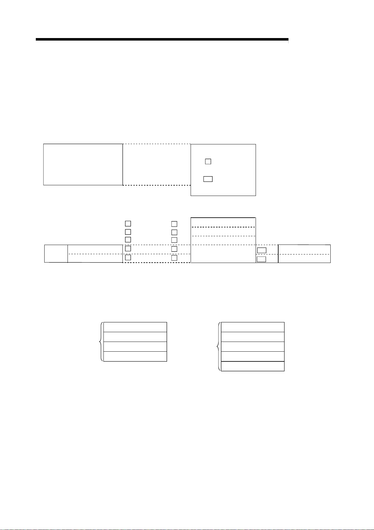
A
5 PRELIMINARY INFORMATION
(4) When using the RIRD command
This is used only when reading to the R2-designated buffer memory.
When the RIRD command is used, the master station buffer memory is used for
the control data size transmission buffer, and the master station buffer memory is
used for the read data size reception buffer.
(Example) To read error code during transmission and during reception
MELSEC-
Programmable controller CPU
Refer to control data (a)
Read data
Error code during transmission
Error code during reception
One word
each
Q/QnA Series A Series
Address
1200
M
H
1201
M
H
1202
M
H
1203
M
H
1204
M
H
Bank 1
Bank 1
Bank 1
Bank 1
Bank 1
+
M
+
M
+
M
+
M
+
M
200
201
202
203
204
Master module
(Transmission buffer)
Address
M
1000
of Q/QnA Series
R2
to 1FF
0
H
of A Series bank 1
(Reception buffer)
H
H
H
H
H
Complete status
Station No., request code
No. of read data (byte)
Read data
to 11FF
H
H
H
Address
R2 1B1
R2 1B2
R2
Error code during transmission
H
storage area
Error code during reception
H
storage area
(a) Control data
Note that the control data differs between the QCPU (Q mode)/QnACPU
and ACPU/QCPU-A (A mode) as shown below.
When using ACPU/QCPU-A (A mode) When using QCPU (Q mode)/QnACPU
Control data Control data
Complete status Complete status
No. of read points (word)
Access code, attribute Access code, attribute
One word
each
Buffer memory address
Station No.
Buffer memory address
No. of read points (word)
5 - 35
Page 94

A
5 PRELIMINARY INFORMATION
(5) When using the RIRCV command
This is used to read a R2-designated buffer memory with executing handshake
automatically between the master station and R2.
When the RIRCV command is used, the master station buffer memory is used for
the control data size transmission buffer, and the master station buffer memory is
used for the read data size reception buffer.
(Example) Reading the reception data
MELSEC-
Programmable controller CPU
Refer to control data (a)
Refer to interlock signal (b)
Reception data size
Read data
Reception data 1
Reception data n
Reception normal read
request signal (RXn2)
Reception error read
request signal (RXn3)
Reception read complete
signal (RYn2)
Master module
(Transmission buffer)
Address
1000
to 11FF
M
H
of Q/QnA Series
R2
0
to 1FF
H
of A Series bank 1
Q/QnA Series A Series
Address
1200
M
H
1201
M
H
1202
M
H
1203
M
H
Bank 1
Bank 1
Bank 1
Bank 1
+
200
M
+
201
M
+
M
202
+
203
M
...
~
13FF
M
H
Bank 1 +
RIRCV command
execution
~
3FF
M
At reception
normal completion
(Reception buffer)
Complete status
H
Station No., request code
H
No. of read data (byte)
H
H
Read data
H
H
H
Address
R2 400
H
R2 401
H
Reception data storage
area
H
401+n
R2
R2
Reception data size
designation area
RIRCV command
execution completion
At reception
error completion
Reading of buffer
memory
5 - 36
Page 95

A
5 PRELIMINARY INFORMATION
(a) Control data
Note that the control data differs between the QCPU (Q mode)/QnACPU
and ACPU/QCPU-A (A mode) as shown below.
When using ACPU/QCPU-A (A mode) When using QCPU (Q mode)/QnACPU
Control data Control data
Complete status Complete status
No. of read points (word)
One word
each
Fixed to 0004
Error confirmation
Buffer memory address
(b) Interlock signal
Note that the interlock signal differs between the QCPU (Q mode)/QnACPU
and ACPU/QCPU (A mode) as shown below.
MELSEC-
Station No.
H
One word
each
Access code, attribute
Buffer memory address
No. of read points (word)
One word
each
When using ACPU/QCPU-A (A mode)
Interlock signal Interlock signal
b15 b8b7 b0
RX (Complete device)
to
RWr (Error code storage device)
to to
RY (Request device)
One word
each
When using QCPU (Q mode)/QnACPU
b15 b8b7 b0
0
RWr
(Error code
storage device)
Complete mode
to
RY (Request device)
RX (Complete device)
5 - 37
Page 96

A
5 PRELIMINARY INFORMATION
(6) Using the FROM command (Not available when using QCPU (Q
mode))
This is used to read the R2-designated buffer memory.
When the FROM command is used, the transmission buffer (master module
buffer memory) for the control data size, and the reception buffer (master module
buffer memory) for the read data size are used.
The data designated with the transmission buffer is read from the R2 buffer
memory using the intelligent device station access request signal and complete
signal (RY(n+1)E and RX(n+1)E).
(Example) Reading the error information
MELSEC-
Address
QnA Series A Series
1000
M
H
1001
M
H
1002
M
H
1003
M
H
1004
M
H
1005
M
H
1006
M
H
1200
M
H
1201
M
H
1202
M
H
1203
M
H
1204
M
H
Bank 1
Bank 1
Bank 1
Bank 1
Bank 1
Bank 1
Bank 1
Bank 1
Bank 1
Bank 1
Bank 1
Bank 1
+
M
+
M
+
M
+
M
+
M
+
M
+
+
M
+
M
+
M
+
M
+
M
....
1212
M
H
1213
M
H
Bank 1
Bank 1
+
M
+
M
0
H
1
H
2
H
3
H
4
H
5
H
6HM
200
201
202
203
204
212
213
H
H
H
H
H
Read data
H
H
Master module
(Transmission buffer)
Station No., request code
Transmission buffer write
data size (byte)
Control
data
Access code, attribute
Buffer memory address
No. of write points (word)
(Reception buffer)
Control
data
Station No., request code
Error code during transmission
Error code during reception
1
*
Dummy area
Quantity
2
*
Complete status
No. of read data (byte)
Error code history
Error code history
....
Address
R2 1A8
R2 1A9
....
R2 1B1
R2 1B2
R2
H
Error code history storage
area
H
....
Error code during transmission
H
storage area
Error code during reception
H
storage area
Intelligent device station
access request signal
(RY(n+1)E)
Intelligent device station
access complete signal
(RX(n+1)E)
FROM command
execution
R2 buffer memory
read request
R2 buffer memory
read completion
5 - 38
Read process
completion
Page 97

A
5 PRELIMINARY INFORMATION
≥
*1 When reading data from the R2 buffer memory using the FROM command, the
control data is designated in the transmission buffer of the corresponding master
module.
MELSEC-
Designated
data
Dummy area – – System
Station No., request
code
Control
data
Designated
Complete
status
Station No.,
request code
Read data size
(byte)
Read data
(byte)
Transmission buffer
write data size (byte)
Quantity (Fixed value) 1 User
Access code, attribute (Fixed value) 0004H User
Buffer memory address
No. of read points
(word)
data
Item Details
Station No. (designate with high-order bytes (bits 8 to 15))
Designate the station No. of the intelligent device station
to be accessed.
Request code (designate with low-order bytes (bits 0 to 7))
Designate the read request code.
(Fixed value) 8
Designate the head address (0
memory.
Designate the data size (No. of words) to be written in so
that the R2 buffer memory address 5FF
5FF
H
(buffer memory address -1) + No. of read points
H or higher) of the buffer
H is not exceeded.
Setting
range
0 to 64 User
H User
10
H to 5FFH User
0
1 to 480
Setting
side
User
User
*2 The same details as the data read from the R2 buffer memory with the FROM
command is stored in the reception buffer of the corresponding master module.
Details
The status when the command is completed is stored.
0 : Normal completion
Other than 0 : Error completion (error code)
Refer to the Master Module User's Manual (Details).
Station No. (designate with high-order bytes (bits 8 to 15))
The station No. of the accessed intelligent device station is stored.
Request code (designate with low-order bytes (bits 0 to 7))
The read request code (10H) is stored.
The total No. of bytes of the read data is stored. System
The target R2 buffer memory data designated with the control data buffer memory address
items and No. of read points is stored.
Setting
side
System
System
System
System
5 - 39
Page 98

A
5 PRELIMINARY INFORMATION
y
5.7.3 Reading the R2 buffer memory
When reading the R2 buffer memory using the transmission/reception buffer, after the
control data is written to the transmission buffer, the data is read from the buffer
memory by turning the intelligent device station access request (complete) signal
(RY(n+1)E, RX(n+1)E) ON and OFF.
MELSEC-
(1) Flow of process
Programmable controller CPU Master station
Remote
input (RX)
Bit device
Word device
2) Intelligent device station access
request ON
6) Intelligent device station access
request OFF
1) Control data
8) Reception data 4) Control data + reception data
Remote
output (RY)
Transmission
buffer
Reception
buffer
(2) Timing chart
Intelligent device station access
request signal (RY(n+1)E)
Intelligent device station access
complete signal (RX(n+1)E)
Programmable controller CPU
word device
Master station
transmission buffer
Master station
reception buffer
R2 buffer memory
2)
1)
3)
3) Read command
5) Intelligent device station access
complete ON
7) Intelligent device station access
complete OFF
Remote
output (RY)
* When using the RIRD (RIRCV) command,
the steps 2) to 7) are carried out automatically.
6)
5)
4)
7)
8)
R2
Remote
input (RX)
Buffer
memory
Carried out with sequence program
Carried out b
R2
No. Details Control side
1) The control data is written to the master station transmission buffer. Program
2) The intelligent device station access request signal (RY(n+1)E) turns ON. Program
3) The contents set in the control data are conveyed to the R2. R2
4) The control data is stored in the master station reception buffer. R2
5) The intelligent device station access complete signal (RX(n+1)E) turns ON. R2
6) The intelligent device station access request signal (RY(n+1)E) turns OFF. Program
7) The intelligent device station access complete signal (RX(n+1)E) turns OFF. R2
8) The reception data is read from the master station reception buffer. Program
5 - 40
Page 99

A
5 PRELIMINARY INFORMATION
r
(3) Program
The program for reading the error codes (R2 1B0H to
below.
Refer to section 5.1 for details on the program conditions.
(a) To use FROM/TO command with ACPU / QCPU-A (A mode)
MELSEC-
1B2H) is shown
R2
Change to bank 1
Set dummy area
Set station No., request
code
Transmission buffer write
data size
Quantity (Fixed)
Access code, attribute
Access destination R2
buffer memory address
No. of read points
Write to transmission buffe
Change to bank 0
Set intelligent device
station access request
Set error read flag 1
Reset intelligent device
station access request
Set error read flag 2
Error read completion
Reset error read flag 2
Reset error read flag 1
Change to bank 1
Read from reception buffer
Change to bank 0
5 - 41
Page 100

A
5 PRELIMINARY INFORMATION
1) Program to change to bank 0
2) Program to change to bank 1
MELSEC-
Specify partial
refresh
Specify bank 0
Execute partial
refresh
Specify partial
refresh
Specify bank 1
Read execution
Execute partial
refresh
(b) When using dedicated commands (RIRD) with QCPU (Q
mode) / QnACPU
When using dedicated commands (RIRD/RIRCV), RY(n+1)E and RY(n+1)F
are used with the dedicated commands, so provisions must be made to
prevent the user from rewriting this signal information.
When the QCPU (Q mode) is used, such provisions need not be made.
Refer to section 5.3(8) for details.
Set R2 station No.
Access code, attribute
R2 buffer memory
address
Reception data size
Read execution
5 - 42
 Loading...