

Page 1
AJ65BT-D75P2-S3
Positioning Module
User’s Manual
(Hardware)
AJ65BT-D75P2-S3
Thank you for purchasing the Mitsubishi general-purpose
programmable logic controller MELSEC-A series.
Prior to use, please read this and relevant manuals thorougly to fully
understand the product.
MODEL AJ65BT-D75P2-U-HE
MODEL
CODE
IB(NA)-66829-E(1112)MEE
13JL48
© 2011 MITSUBISHI ELECTRIC CORPORATION
Page 2
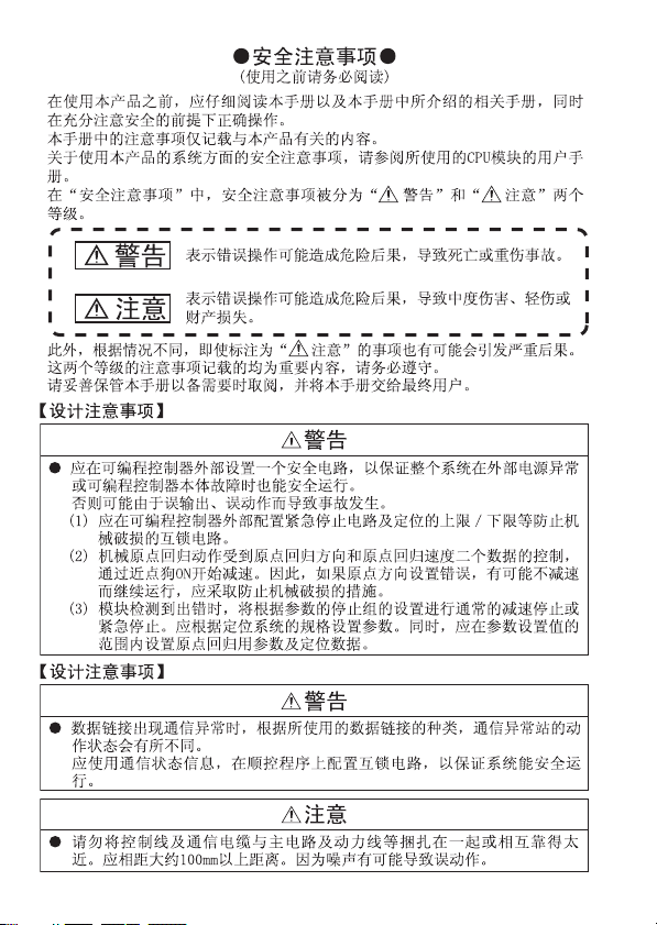
SAFETY PRECAUTIONS
(Read these precautions before using.)
When using Mitsubishi equipment, thoroughly read this manual and the
associated manuals introduced in the manual. Also pay careful attention to safety
and handle the module properly.
These precautions apply only to Mitsubishi equipment. Refer to the CPU module
user's manual for a description of the programmable controller system safety
precautions.
In this manual, the safety precautions are classified into two levels:
" WARNING" and " CAUTION".
Indicates that incorrect handling may cause
WARNING
CAUTION
Under some circumstances, failure to observe the precautions given under
" CAUTION" may lead to serious consequences.
Observe the precautions of both levels because they are important for personal
and system safety.
Make sure that the end users read this manual and then keep the manual in a safe
place for future reference.
hazardous conditions, resulting in death or severe
injury.
Indicates that incorrect handling may cause
hazardous conditions, resulting in minor or moderate
injury or property damage.
[Design Precautions]
WARNING
● Install a safety circuit external to the programmable controller that keeps the
entire system safe even when there are problems with the external power
supply or the programmable controller main module.
An accident may occur by a false output or a malfunction.
1) Configure interlock circuits such as an emergency stop circuit and
high/low limits of positioning to prevent damages to the equipment.
Configure these circuits outside of the programmable controller.
2) The zero return action is controlled by two kinds of data: the zero return
direction and zero return speed. Since the system keeps operating
without decelerating if a wrong zero return direction is set, apply damage
prevention measures to the equipment.
A-1
Page 3
[Design Precautions]
WARNING
● When data link becomes faulty, the operation of communication faulty station
vary depending on its data link type. Configure an interlock circuit in the
sequence program using the communication status information so the safety
of the entire system is always maintained.
Refer to the manual of each data link for how to confirm communication
faulty stations and the operation status during a communication error.
[Design Precaution]
CAUTION
● Do not bunch the control wires or communication cables with the main circuit
or power wires, or install them close to each other.
They should be installed 100mm (3.9 in) or more from each other.
Not doing so could result in noise that would cause malfunction.
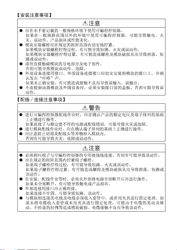
[Installation Precautions]
WARNING
● Use the programmable controller in an environment that meets the general
specifications contained in this manual. Using this programmable controller
in an environment outside the range of the general specifications could result
in electric shock, fire, malfunction , and damage to or deterioration of the
product.
● Tighten the module installation screws within the range of specified torque. If
the module installation screws are loose, it may result in short circuits, fire or
malfunction. Tightening the module installation screws too far may cause
damages to the screws and /or the module, resulting in fallout, short circuits
or malfunction.
● Do not directly touch the module's conductive parts. Doing so could cause
malfunction or trouble in the module.
● Securely install the connectors for the drive unit and peripheral devices into
the module connectors until a clicking sound comes. Improper installation
may cause false contact, resulting in false input and output.
● When the drive unit and peripheral device are not connected, be sure to
attach the connector cover. Failure to do so may cause malfunction.
A-2
Page 4

[Wiring/Connection Precautions]
CAUTION
● Be sure to shut off all phases of the external power supply used by the
system before installation or wiring.
Not doing so can cause the product to be damaged or malfunction.
● Be sure to ground the FG terminal to the class-D (class-3) or higher
grounding. Otherwise there will be a danger of malfunctions.
● Use applicable solderless terminals and tighten them with the specified
torque.If any solderless spade terminal is used, it may be disconnected when
the terminal screw comes loose, resulting in failure.
● When wiring the programmable controller, check the rated voltage and
terminal layout of the wiring, and make sure the wiring is done correctly.
Connecting a power supply that differs from the rated voltage or wiring it
incorrectly may cause fire or failure.
● Be sure to confirm terminal assignments before wiring the module.
● Be sure there are no foreign substances such as sawdust or wiring debris
inside the module. Such debris could cause fire, failure or malfunction.
● Tighten the terminal screws with the specified torque. Loose terminal screws
may cause a short circuit, fire or erroneous operation. Tightening the
terminal screws too far may cause damage to the screws and /or the
module, resulting in fallout, short circuits, or malfunction.
● Before beginning any installation or wiring work, make sure all phases of the
power supply have been obstructed from the outside. Failure to completely
shut off the power supply phases may cause electric shock and/or damage
to the module.
● When turning on the power or operating the module after installation or
wiring work, be sure the module's terminal covers are correctly attached.
Failure to attach the terminal covers may result in electric shock.
● External connectors shall be correctly soldered. Imperfect connections could
result in short circuit or erroneous operation.
● When connecting the communication and power supply cables to the
module, always run them in conduits or clamp them.
Not doing so can damage the module and cables due to loose, moved or
accidentally pulled cables or can cause a malfunction due to a cable
connection fault.
● Do not install the control lines together with the communication cables, or
bring them close to each other. Failure to do so may cause malfunctions due
to noise.
A-3
Page 5
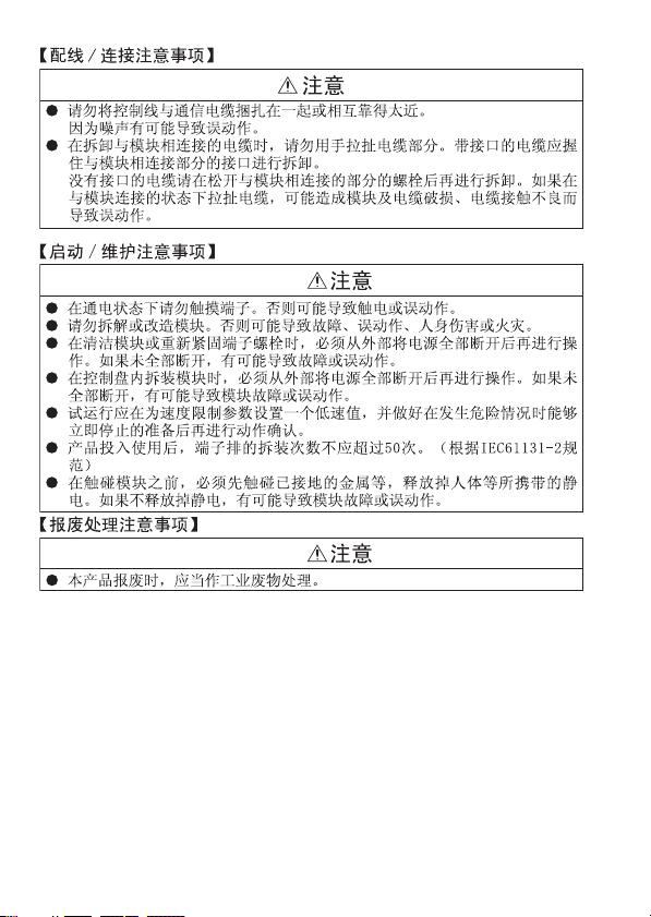
[Wiring/Connection Precautions]
CAUTION
● When disconnecting the communication and power supply cables from the
module, do not hold and pull the cable part.
Disconnect the cables after loosening the screws in the portions connected
to the module. Pulling the cables connected to the module can damage the
module and cables or can cause a malfunction due to a cable connection
fault.
[Startup and Maintenance Precautions]
CAUTION
● Do not touch the terminals without having the power supply shut down
externally at all phases. Doing so may result in malfunctions.
● Do not disassemble or modify the modules.
Doing so could cause failure, malfunction, injury or fire.
● Do not drop the module or give it hard impact since its case is made of resin.
Doing so can damage the module.
● Make sure to switch all phases of the external power supply off before
cleaning.
If you do not switch off the external power supply, it will cause failure or
malfunction.
● Make sure to switch all phases of the external power supply off before
mounting or removing the module. If you do not switch off the external power
supply, it will cause failure or malfunction of the module.
● Before performing a test operation, set slow speed for the speed limit
parameter value, and prepare to stop immediately in case any dangerous
conditions occur.
● Do not install/remove the terminal block more than 50 times after the first use
of the product. (IEC 61131-2 compliant)
● Before handling the module, always touch grounded metal, etc. to discharge
static electricity from the human body.
Failure to do so can cause the module to fail or malfunction.
[Disposal Precautions]
CAUTION
● When disposing of this product, treat it as industrial waste.
A-4
Page 6
A-5
Page 7
A-6
Page 8
A-7
Page 9

CONDITIONS OF USE FOR THE PRODUCT
(1) Mitsubishi programmable controller ("the PRODUCT") shall be used in
conditions;
i) where any problem, fault or failure occurring in the PRODUCT, if any,
shall not lead to any major or serious accident; and
ii) where the backup and fail-safe function are systematically or
automatically provided outside of the PRODUCT for the case of any
problem, fault or failure occurring in the PRODUCT.
(2) The PRODUCT has been designed and manufactured for the purpose of
being used in general industries.
MITSUBISHI SHALL HAVE NO RESPONSIBILITY OR LIABILITY
(INCLUDING, BUT NOT LIMITED TO ANY AND ALL RESPONSIBILITY
OR LIABILITY BASED ON CONTRACT, WARRANTY, TORT, PRODUCT
LIABILITY) FOR ANY INJURY OR DEATH TO PERSONS OR LOSS OR
DAMAGE TO PROPERTY CAUSED BY the PRODUCT THAT ARE
OPERATED OR USED IN APPLICATION NOT INTENDED OR
EXCLUDED BY INSTRUCTIONS, PRECAUTIONS, OR WARNING
CONTAINED IN MITSUBISHI'S USER, INSTRUCTION AND/OR SAFETY
MANUALS, TECHNICAL BULLETINS AND GUIDELINES FOR the
PRODUCT.
("Prohibited Application")
Prohibited Applications include, but not limited to, the use of the PRODUCT
in;
• Nuclear Power Plants and any other power plants operated by Power
companies, and/or any other cases in which the public could be
affected if any problem or fault occurs in the PRODUCT.
• Railway companies or Public service purposes, and/or any other cases
in which establishment of a special quality assurance system is
required by the Purchaser or End User.
• Aircraft or Aerospace, Medical applications, Train equipment, transport
equipment such as Elevator and Escalator, Incineration and Fuel
devices, Vehicles, Manned transportation, Equipment for Recreation
and Amusement, and Safety devices, handling of Nuclear or
Hazardous Materials or Chemicals, Mining and Drilling, and/or other
applications where there is a significant risk of injury to the public or
property.
A-8
Page 10

Notwithstanding the above, restrictions Mitsubishi may in its sole discretion,
authorize use of the PRODUCT in one or more of the Prohibited
Applications, provided that the usage of the PRODUCT is limited only for
the specific applications agreed to by Mitsubishi and provided further that
no special quality assurance or fail-safe, redundant or other safety features
which exceed the general specifications of the PRODUCTs are required.
For details, please contact the Mitsubishi representative in your region.
A-9
Page 11

ABOUT THE MANUALS
The following product are available for this equipment.
Refer to the table given below to choose suitable manuals.
Detailed manual
Manual name
AJ65BT-D75P2-S3 Positioning Module User's Manual
Related Manual
Manual name
Positioning module software package type
SW1IVD-AD75P Operating Ma nual
CC-Link System Master Local type AJ61BT11/A1SJ61BT11 Module
User’s Manual
CC-Link System Master Local Module type
AJ61QBT11/A1SJ61QBT11 User's Manual
CC-Link System Master/Local type QJ61BT11N Module User's
Manual
Manual number
(Model code)
IB-66824
(13JL46)
Manual number
(Model code)
IB-66714
(13J915)
IB-66721
(13J872)
IB-66722
(13J873)
SH-080394E
(13JR64)
COMPLIANCE WITH THE EMC AND LOW VOLTAGE DIRECTIVES
1) Method of ensuring compliance
To ensure that Mitsubishi programmable controllers maintain EMC and Low
Voltage Directives when incorporated into other machinery or equipment,
certain measures may be necessary. Please refer to one of the following
manuals.
• QCPU User's Manual (Hardware Design, Maintenance and Inspection)
• Safety Guidelines
(This manual is included with the CPU module or base unit.)
The CE mark on the side of the programmable controller indicates
compliance with EMC and Low Voltage Directives.
2) Additional measures
To ensure that this product maintains EMC and Low Voltage Directives,
please refer to one of the manuals listed under (1).
A-10
Page 12

CONTENTS
1. OVERVIEW .................................................................................................... 1
2. PERFORMANCE SPECIFICATIONS............................................................. 1
3. NAME OF EACH PART .................................................................................. 2
4. LOADING AND INSTALLATION .................................................................... 4
4.1 Handling precautions................................................................................ 4
4.2 Installation environment ........................................................................... 4
5. WIRING DATA-LINK CABLES ....................................................................... 5
5.1 Precautionary items when handling twisted cables.................................. 5
5.2 Wiring a twisted cable .............................................................................. 5
6. EXTERNAL WIRING ...................................................................................... 6
6.1 Precautionary notes when wiring ............................................................. 6
6.2 I/O Interface.............................................................................................. 7
7. EXTERNAL DIMENSIONS ........................................................................... 10
A-11
Page 13

1. OVERVIEW
This manual describes how to install AJ65BT-D75P2-S3 Positioning
Module (hereafter abbreviated as D75P2) and how to wire them with
external devices.
IMPORTANT
1) The following software packages will be needed if a D75P2 is to be used:
For DOS/V personal computers : SW1IVD-AD75P or later
2) Software version D or later will be required for AD75TU.
After unpacking D75P2, please confirm that the following products are
contained.
(Main module) AJ65BT-D75P2-S3 1
(Connector for external wiring) 10136-3000VE 2
(Connector cover) 10336-52F0-008 2
Model name Quantity
2. PERFORMANCE SPECIFICATIONS
The performance specifications for the D75P2 are shown below.
Refer to CPU module User's Manual to use for D75P2 general
specifications.
Item Specifications
Maximum output pulse
Maximum connection
distance between servos
Type of CC-Link station Intelligent device station
Number of occupied station 4 stations (RX/RY each 128 points,RWr/RWw each 16 points)
External power supply 24 V DC (20.4 to 26.4 V DC)
Applicable wire size 0.75 to 2.00 mm
Module installation screws
Applicable DIN rails TH35-7.5Fe, TH35-7.5AI, TH35-15Fe (conforms to JIS-C2B12)
Applicable solderless terminal RAV 1.25-3.5, RAV 2-3.5
24 V DC internal current
consumption
Noise durability
Dielectric withstand voltage
Insulation resistor
External dimensions 63.5[2.5](H) × 170[6.7](W) × 80[3.1](D) mm [inch]
Weight 0.50 [1.1] kg [lb]
When connected to a differential driver: 400kpps
When connected to an open collector: 200kbps
When connected to a differential driver: 10m (32.81 ft.)
When connected to an opem collector: 2m(6.56 ft.)
2
Over M4 × 0.7 mm(0.03 in) × 16 mm(0.6 in)
DIN rail attachment is possible
0.30 A
Noise voltage 500 Vp-p, noise width 1 μs
(by the noise simulator with the noise frequency 25 to 60 Hz)
Batch power supply/communication type-batch external I/O,
500 V AC for 1 minute
Batch power supply /communication type batch external I/O,
500 V DC 10 m Ω or more by the insulation resistance tester.
1
Page 14

3. NAME OF EACH PART
1)
3)4)2)
11)
8)
10)
No. Name Description
1) Corresponding axis LED display
2) CC-Link status LED display
3) Transmission speed setting switch Sets the data communication speed.
4) Station number setting switch Sets the D75P2 station number.
5) LED display mode select switch
6) Reset switch
7) Drive unit connectors (AX1, AX2)
8) 17 segment LED
9) RS-422 peripheral connector For connection to peripheral devices.
10) Terminal block
Maintenance connector for
11)
manufacturer
9)
Indicates the axis for the "8)17 segment LED"
message.
Shows the power supply and data communication
conditions.
Display information is switched between "1)
Corresponding axis LED display" and "8) 17 segment
LED" each time the switch is pressed.
When pressed, it initializes input signals, remote
registers and operation processing.
For connection to the drive unit, mechanical system
input and manual pulse generato r.
*1
Displays messages indicating the operation status
according to the mode.
For connection to the master module.
Terminal block
assignment diagram
1357
This connector is for manufacturer use only. Do not
open the cover.
DA DG
2
4
DB SLD (FG)
+24V 24G
6
5)
6)
7)
2
Page 15

*1 For modules of the hardware version L or later, the display part is changed to
a LED module. (The display contents remain the same as the 17-segment
LED.)
Before change
After change
17 segment
Example of
display: IDL
LED module
Example of
display: IDL
3
Page 16

4. LOADING AND INSTALLATION
The following is explanations of the handling precautions and
installation environment which is common to modules when handling
D75P2 from unpacking to installation.
For the details of loading and installation of the module, refer to User's
Manual of programmable controller CPU module to be used.
4.1 Handling precautions
1) The module case is made of plastic. Be sure not to drop it
or subject it to strong vibration.
2) Do not remove the printed circuit board of the module from
the case. This may cause malfunctions.
3) Be careful not to let foreign matters such as filings or wire
chips get inside the module during wiring. When such
matters do enter, be sure to remove them.
4) Tighten the module installation screws and terminal screws
within the following tightening torque range.
Screw Tightening Torque Range
Module installation screws (M4 screws)
Terminal screws
Terminal block installation screws (M4 screws)
4.2 Installation environment
Do not install the A series programmable controller in the following
environments.
1) Where the ambient temperature exceeds the 0 to 55°C
range.
2) Where the ambient humidity exceeds the 10 to 90 % RH
range.
3) Where condensation is produced by sudden temperature
changes.
4) Where corrosive or combustible gas is present.
5) Where dust, iron powder and other conductive powder, oil
mist, salt, or organic solvents are prevalent.
6) In direct sunlight.
7) Where a strong electric or magnetic field is generated.
8) Where vibration and shock may be transmitted directly to
the module.
0.78 to 1.18N•m
(6.9 to 10.4lbinch)
0.59 to 0.88N•m
(5.2 to 7.8lbinch)
0.78 to 1.18N•m
(6.9 to 10.4lbinch)
4
Page 17

5. WIRING DATA-LINK CABLES
This section describes the method for wiring a twisted cable between
the D75P2 and master module.
5.1 Precautionary items when handling twisted cables
Do not handle the twisted cables in the following manner. These
extreme activities will damage the cables.
1) Applying pressure using a sharp object.
2) Twisting the cable extensively.
3) Pulling the cable with an extremely large force (more than
tolerable tension).
4) Stepping on the cable.
5) Placing any object atop.
6) Scratching the cable cover.
5.2 Wiring a twisted cable
Wire the twisted cable between the D75P2 and master module in the
following manner:
Master module side AJ65BT-D75P2-S3
Terminal
resistor
DA
DB
DG
SLD
FG
(Blue)
(White)
(Yellow)
(Blue)
(White)
(Yellow)
(Blue)
DA
(White)
DB
(Yellow)
DG
SLD
24V
24G 24G
FG FG
I/O module side
(Blue)
DA
(White)
DB
(Yellow)
DG
SLD
24V
5
Terminal
resistor
Page 18

6. EXTERNAL WIRING
Precautionary notes when wiring as well as the I/O interface are
described below.
6.1 Precautionary notes when wiring
This section describes the precautionary notes for the wiring process
between the D75P2 and outside (drive unit).
(1) Length of connection cable between the D75P2 and drive unit
(a) When an open collector is used, the maximum cable length is
2 m (6.56 ft.). However, this value might change according to
the drive unit specifications.
Perform wiring after verifying the specifications for the drive
unit to be used.
(b) When a differential driver is used, the maximum cable length is
10 m (32.81 ft.).
To extend the distance between the D75P2 and drive unit, use
a differential driver.
(2) Wiring for I/O signals
(a) Avoid bundling with or installing near the proximity of power
wires or main circuit wires.
(b) When installing near the proximity of power wires or main
circuit wires, use separate ducts or piping.
(c) If bundling cannot be avoided, use a batch shielded cable and
ground it on the programmable controller side.
(d) When wiring is done via piping, be sure to ground the pipe.
(e) If the connection cable is long or the main circuit wiring is in
the proximity, operation error may occur due to noise.
6
Page 19

6.2 I/O Interface
I/O
classification
Input
External wiring
When the high
limit LS is not
used
When the low
limit LS is not
used
*
24VDC
5V
5VDC
A
B
0V
Manual pulser
(MR-HDP01)
When MR-J2- A
is used
: Wiring required, : Wiring performed as required
Pin
Internal circuit Signal name
number
11
12
13
14
15
16
35
36
(+)
9
(–)
27
(+)
10
(–)
7
RD
INP
8
VDD
26
COM
6 Zero-point
LZ
24
LZR
25 Common
Near-point
signal
High limit
LS FLS
Low limit
LS RLS
Stop signal
Speed/
position
switch
signal
External
start
Common
Manual
pulser
phase A
Manual
pulser
phase B
Drive unit
ready READY
In-position
signal INPS
Common
DOG
STOP
CHG
STRT
COM
PULSER
A+
PULSER
A–
PULSER
B+
PULSER
B–
COM
signal PGO
PGO
COM
Wiring
requirement
7
Page 20

I/O
classification
External wiring
When MR-J2- A
is used
Output
*1 Select open collector output or differential output, according to the drive unit
Pin
Internal circuit Signal name
number
5
CR
COM
23 Common
SG
1
19
2
20
PP
3(+)
PG
21(-)
NP
4(+)
NG
22(-)
Deviation
counter
clear
CW
Phase A
PULSE
CCW
Phase B
SIGN
CW
Phase A
PULSE
CCW
Phase B
SIGN
CLEAR
CLEAR
COM
PULSE
F
PULSE
COM
PULSE
R
PULSE
COM
PULSE
F +
PULSE
F –
PULSE
R +
PULSE
R –
Wiring
requirement
*1
*1
used.
Remarks
The following shows the relationship between the pulse output mode
selected via the parameter and the pulse output according to "positive
logic/negative logic selection."
Mode selection
CW
CCW
PULSE
SIGN
Aφ
Bφ
Positive logic Negative logic
Forward rotation Reverse rotation Forward rotation Reverse rotation
High
LOW
LOW
High
8
Page 21

* To construct an absolute position detection system, perform wiring as shown
below:
I/O
classificationExternal wiring
When MR-J2- A
is used
Input
Output
Pin
Internal circuit
No.
D01
17
ZSP
18
TLC
34
VCC
COM
33
29
SON
30
PC
31
TL
SG
32
Signal name [abbreviation]
bit0
[DO1]
bit1
[ZSP]
ABS
data
[TLC]
[COM]
[SON]
mode
[COM]
When ABS transfer
mode OFF
Upper level: MR-H
*2
Lower level: MR-J2
Positioning
complete [PF]
Positioning
complete [D01]
Zero speed
During torque
control
Common
[COM]
Servo ON
Proportional
control [PC]
During torque
control [TL]
Common
[COM]
When ABS
transfer
mode ON
ABS data
ABS data
transmission
preparation
complete
Common
Servo ON
ABS transfer
[ABSM]
ABS request
[ABSR]
Common
[ZSP]
[TLC]
[SON]
–
[DI3]
–
[DI4]
*3
Remarks
*2 Signals in the ABS transfer mode are shown.
*3 Signals in the normal state (not in the ABS transfer mode) are shown. For
details, refer to the specification/instruction manual for the servo amplifier
used.
9
Page 22

7. EXTERNAL DIMENSIONS
2- 4.5 installation hole
161
170
9.5
71
63.5
80
Unit:mm (inch)
10
Page 23

MEMO
11
Page 24

Country/Region Sales office/Tel
U.S.A Mitsubishi Electric Automation Inc.
500 Corporate Woods Parkway Vernon
Hills, IL 60061, U.S.A.
Tel : +1-847-478-2100
Brazil MELCO-TEC Rep. Com.e Assessoria
Tecnica Ltda.
Rua Correia Dias, 184,
Edificio Paraiso Trade Center-8 andar
Paraiso, Sao Paulo, SP Brazil
Tel : +55-11-5908-8331
Germany Mitsubishi Electric Europe B.V. German
Branch
Gothaer Strasse 8 D-40880 Ratingen,
GERMANY
Tel : +49-2102-486-0
U.K Mitsubishi Electric Europe B.V. UK
Branch
Travellers Lane, Hatfield, Hertfordshire.,
AL10 8XB, U.K.
Tel : +44-1707-276100
Italy Mitsubishi Electric Europe B.V. Italian
Branch
Centro Dir. Colleoni, Pal. Perseo-Ingr.2
Via Paracelso 12, I-20041 Agrate Brianza.,
Milano, Italy
Tel : +39-039-60531
Spain Mitsubishi Electric Europe B.V. Spanish
Branch
Carretera de Rubi 76-80,
E-08190 Sant Cugat del Valles,
Barcelona, Spain
Tel : +34-93-565-3131
France Mitsubishi Electric Europe B.V. French
Branch
25, Boulevard des Bouvets, F-92741
Nanterre Cedex, France
Tel : +33-1-5568-5568
South Africa Circuit Breaker Industries Ltd.
Private Bag 2016, ZA-1600 Isando,
South Africa
Tel : +27-11-928-2000
HEAD OFFICE : TOKYO BUILDING, 2-7-3 MARUNOUCHI, CHIYODA-KU, TOKYO 100-8310, JAPAN
NAGOYA WORKS : 1-14, YADA-MINAMI 5-CHOME, HIGASHI-KU, NAGOYA, JAPAN
Country/Region Sales office/Tel
China Mitsubishi Electric Automation
(China) Ltd.
4/F Zhi Fu Plazz, No.80 Xin Chang Road,
Shanghai 200003, China
Tel : +86-21-6120-0808
Taiwan Setsuyo Enterprise Co., Ltd.
6F No.105 Wu-Kung 3rd.Rd, Wu-Ku
Hsiang, Taipei Hsine, Taiwan
Tel : +886-2-2299-2499
Korea Mitsubishi Electric Automation
Korea Co., Ltd.
1480-6, Gayang-dong, Gangseo-ku
Seoul 157-200, Korea
Tel : +82-2-3660-9552
Singapore Mitsubishi Electric Asia Pte, Ltd.
307 Alexandra Road #05-01/02,
Mitsubishi Electric Building,
Singapore 159943
Tel : +65-6470-2480
Thailand Mitsubishi Electric Automation (Thailand)
Co., Ltd.
Bang-Chan Industrial Estate No.111
Moo 4, Serithai Rd, T.Kannayao,
A.Kannayao, Bangkok 10230 Thailand
Tel : +66-2-517-1326
Indonesia P.T. Autoteknindo Sumber Makmur
Muara Karang Selatan, Block A/Utara
No.1 Kav. No.11 Kawasan Industri
Pergudangan Jakarta - Utara 14440,
P.O.Box 5045 Jakarta, 11050 Indonesia
Tel : +62-21-6630833
India Messung Systems Pvt, Ltd.
Electronic Sadan NO:III Unit No15,
M.I.D.C Bhosari, Pune-411026, India
Tel : +91-20-2712-3130
Australia Mitsubishi Electric Australia Pty. Ltd.
348 Victoria Road, Rydalmere,
N.S.W 2116, Australia
Tel : +61-2-9684-7777
When exported from Japan, this manual does not require application to the Ministry
of Economy, Trade and Industry for service transaction permission.
Specifications subject to change without notice.
 Loading...