

Page 1

AJ65BT-D75P2-S3 Positioning Module
User's Manual
Page 2

Page 3
SAFETY PRECAUTIONS
(Read these precautions before using this product.)
Before using this product, please read this manual and the relevant manuals carefully and pay full
attention to safety to handle the product correctly.
The precautions given in this manual are concerned with this product only. For the safety precautions of
the programmable controller system, refer to the user's manual for the CPU module used.
In this manual, the safety instructions are classified into two levels: "
WARNING" and " CAUTION".
Under some circumstances, failure to observe the precautions given under " CAUTION" may lead to
serious consequences.
Observe the precautions of both levels because they are important for personal and system safety.
Make sure that the end users read this manual and then keep the manual in a safe place for future
reference.
A - 1
Page 4

[Design Precautions]
WARNING
Failure to observe this could lead to accidents for incorrect outputs or malfunctioning.
Configure safety circuits external to the programmable controller to ensure that the entire
system operates safely even when a fault occurs in the external power supply or the
programmable controller.
Failure to do so may result in an accident due to an incorrect output or malfunction.
(1) Configure an emergency stop circuit and interlock circuit such as a positioning upper
limit/lower limit to prevent mechanical damage outside the programmable controller.
(2) The machine zero point return operation is controlled by the zero point return direction
and zero point return speed data. Deceleration starts when the near-point dog turns ON.
Thus, if the zero point return direction is incorrectly set, deceleration will not start and the
machine will continue to travel. Configure an interlock circuit to prevent mechanical
damage outside the programmable controller.
(3) When the positioning module detects an error, the motion slows down and stops or the
motion suddenly stops, depending on the stop group setting in parameter.
Set the parameters to meet the specifications of the positioning control system used.
In addition, set the OPR parameters and positioning data within the specified setting range.
When a data link results in a communication error, the operating status of the station in
communication error changes depending on the type of the used data link. Using the
communication status information, configure an interlock circuit in the sequence program to
ensure that the system will operate safely.
For the method of checking the station in communication error and its operating status at
communication error, refer to the corresponding data link manual.
[Design Precautions]
CAUTION
Do not install the control lines or communication cables together with the main circuit lines or
power cables.
Keep a distance of 100mm or more between them.
Failure to do so may result in malfunction due to noise.
A - 2
Page 5

[Installation Precautions]
CAUTION
Use the programmable controller in an environment that meets the general specifications in
this manual.
Failure to do so may result in electric shock, fire, malfunction, or damage to or deterioration of
the product.
Securely fix the module using the DIN rail or mounting screws and fully tighten the mounting
screws within the specified torque range. If the screws are loose, it may result in fallout, short
circuits, or malfunctions. Tightening the screw too far may cause damages to the screws and/or
the module, resulting in a fallout, short circuits, or malfunctions.
Securely connect the external device connection connector and peripheral device connection
connector into the module connector until a click is heard.
Improper connection could lead to a connection fault, and to incorrect inputs and outputs.
When not connecting the drive unit and peripheral device, always install a cover on the
connector section.
Failure to observe this could lead to malfunctioning.
[Wiring Precautions]
WARNING
Check the rated voltage and terminal layout before wiring to the programmable controller, and
connect the cables correctly. Connecting a power supply with a different voltage rating or
incorrect wiring may cause a fire or failure.
Check the terminal layout before wiring to the module, and connect the cables correctly.
Prevent foreign matter such as dust or wire chips from entering the module.
Such foreign matter can cause a fire, failure, or malfunction.
[Wiring Precautions]
!
CAUTION
Tighten the terminal screws within the range of the specified torque.
If the terminal screws are loose, it may result in short circuits, or malfunctions. Tightening the
terminal screws too far may cause damages to the terminal screws and/or the module, resulting
in short circuits, or malfunctions.
Be sure there are no foreign substances such as sawdust or wiring debris inside the module.
Such debris could cause fires, failure, or malfunction.
Individually ground the FG terminal of the programmable controller with a ground resistance of
100 ohms or less. Failure to do so may result in malfunction.
Place the cables in a duct or clamp them.
If not, dangling cable may swing or inadvertently be pulled, resulting in damage to the module
or cables or malfunction due to poor contact.
Keep a certain distance between the control wires and the communication cables.
Noise can cause a malfunction.
When disconnecting a cable from the module, do not pull on the cable itself. Disconnect cables
not fitted with a connectors by holding and pulling the cable connector.
Disconnect cables not fitted with a connector by removing the screws from the part connected
to the module can cause damage to the module or cable, or ,malfunction due to cable
connection faults.
A - 3
Page 6

[Startup and Maintenance Precautions]
!
CAUTION
Do not touch any terminal while power is on.
Doing so will cause electric shock or malfunction.
Never disassemble or modify the module.
Failure to observe this could lead to trouble, malfunctioning, injuries or fires.
Switch off all phases of the externally supplied power used in the system before cleaning or
tightening the screws.
Failure to turn all phases OFF could lead to electric shocks.
Make sure to install or remove the module from the panel after switching off all phases of the
externally supplied power for the system.
Failure to turn all phases OFF could lead to module trouble or malfunctioning.
Before starting test operation, set the parameter speed limit value to the slowest value, and
make sure that operation can be stopped immediately if a hazardous state occurs.
Do not install/remove the terminal block more than 50 times after the first use of the product.
(IEC 61131-2 compliant)
Always make sure to touch the grounded metal to discharge the electricity charged in the body,
etc., before touching the module.
Failure to do so may cause a failure or malfunctions of the module.
[Precautions for use]
!
CAUTION
Note that when the reference axis speed is designated for interpolation operation, the speed of
the partner axis (2nd axis) may be larger than the set speed (larger than the speed limit value).
[Disposal Precautions]
!
CAUTION
When disposing of the product, handle it as industrial waste.
A - 4
Page 7

CONDITIONS OF USE FOR THE PRODUCT
(1) Mitsubishi programmable controller ("the PRODUCT") shall be used in conditions;
i) where any problem, fault or failure occurring in the PRODUCT, if any, shall not lead to any major or
serious accident; and
ii) where the backup and fail-safe function are systematically or automatically provided outside of the
PRODUCT for the case of any problem, fault or failure occurring in the PRODUCT.
(2) The PRODUCT has been designed and manufactured for the purpose of being used in general
industries.
MITSUBISHI SHALL HAVE NO RESPONSIBILITY OR LIABILITY (INCLUDING, BUT NOT LIMITED
TO ANY AND ALL RESPONSIBILITY OR LIABILITY BASED ON CONTRACT, WARRANTY, TORT,
PRODUCT LIABILITY) FOR ANY INJURY OR DEATH TO PERSONS OR LOSS OR DAMAGE TO
PROPERTY CAUSED BY the PRODUCT THAT ARE OPERATED OR USED IN APPLICATION NOT
INTENDED OR EXCLUDED BY INSTRUCTIONS, PRECAUTIONS, OR WARNING CONTAINED IN
MITSUBISHI'S USER, INSTRUCTION AND/OR SAFETY MANUALS, TECHNICAL BULLETINS AND
GUIDELINES FOR the PRODUCT.
("Prohibited Application")
Prohibited Applications include, but not limited to, the use of the PRODUCT in;
• Nuclear Power Plants and any other power plants operated by Power companies, and/or any other
cases in which the public could be affected if any problem or fault occurs in the PRODUCT.
• Railway companies or Public service purposes, and/or any other cases in which establishment of a
special quality assurance system is required by the Purchaser or End User.
• Aircraft or Aerospace, Medical applications, Train equipment, transport equipment such as Elevator
and Escalator, Incineration and Fuel devices, Vehicles, Manned transportation, Equipment for
Recreation and Amusement, and Safety devices, handling of Nuclear or Hazardous Materials or
Chemicals, Mining and Drilling, and/or other applications where there is a significant risk of injury to
the public or property.
Notwithstanding the above, restrictions Mitsubishi may in its sole discretion, authorize use of the
PRODUCT in one or more of the Prohibited Applications, provided that the usage of the PRODUCT is
limited only for the specific applications agreed to by Mitsubishi and provided further that no special
quality assurance or fail-safe, redundant or other safety features which exceed the general
specifications of the PRODUCTs are required. For details, please contact the Mitsubishi representative
in your region.
A - 5
Page 8

REVISIONS
The manual number is given on the bottom left of the back cover.
*
Print Date * Manual Number Revision
Apr., 1998 IB (NA)-66824-A First printing
Apr., 2003 IB (NA)-66824-B Complete review
Oct., 2003 IB (NA)-66824-C Complete review
Feb.,2004 IB (NA)-66824-D
Partial correction addition
CONTENTS, Section 3.5, Section 5.6.2, Section 7.1.2, Section 8.2.5,
Section 8.2.6, Section 10.1.2, Section 10.3.3 to Section 10.3.5,
Section 10.3.8, Appendix 13, INDEX
Jun., 2005 IB (NA)-66824-E
Partial correction addition
SAFETY INSTRUCTIONS, Generic Terms and Abbreviations,
Section 3.4.2, Section 4.2.2, Section 4.3, Section 4.5.1, Section 4.5.3,
Section 4.8.1, Section 5.1.2, Section 5.2.1, Section 5.3, Section 5.7.2,
Section 6.1.1, Section 6.6.1, Section 6.6.5, Section 8.1.1,
Section 8.2.4 to Section 8.2.8, Section 8.5, Section 9.1.2,
Section 9.15, Section 9.2.6, Section 9.2.8 to Section 9.2.11,
Section 10.3.9, Section 11.3.1, Section 12.2.1, Section 14.4.3,
Section 12.4.4, Section 12.5.1, Section 12.5.2, Section 12.7.1,
Section 12.7.5, Section 12.7.6, Section 13.4, Section 14.2,
Section 14.3, Appendix 5.1, Appendix 11, Appendix 12
Jul., 2006 IB (NA)-66824-F
Partial correction addition
Appendix 7.1, INDEX
Sep., 2007 IB(NA)-66824-G
Partial revisions
Section 5.1.2, Section 5.2.1, Section 5.6.1, Section 5.7.1
Apr., 2015 IB(NA)-66824-H
Addition
CONDITIONS OF USE FOR THE PRODUCT
Partial correction addition
SAFETY PRECAUTIONS, INTRODUCTION, ABOUT MANUALS,
COMPLIANCE WITH EMC AND LOW VOLTAGE DIRECTIVES,
GENERIC TERMS AND ABBREVIATIONS, Section 1.3, 2.3, 2.4, 3.1,
3.2, 3.7.1, 3.7.3, 3.7.4, 4.1.2, 4.1.3, 4.2.1, 4.3, 4.5.1, 4.5.2, 4.8.1,
5.1.1, 5.2.3, 5.3, 5.5, 6.1.1, 6.1.2, 9.1.4, 9.1.5, 9.2.7, 10.1.1, 10.1.2,
10.3.5, 10.3.8, 10.4.1, 10.4.2, 12.3.2, 12.4.3, 12.4.4, 12.5.3, 13.4,
Appendix 1, 2, 3.2, 5.1, 5.2, 5.3, 6.1, 7.1, 8.1, 9.1, 11, 12,
WARRANTY
Japanese Manual Version SH-3654-J
This manual confers no industrial property rights or any rights of any other kind, nor does it confer any patent licenses.
Mitsubishi Electric Corporation cannot be held responsible for any problems involving industrial property rights which
may occur as a result of using the contents noted in this manual.
1998 MITSUBISHI ELECTRIC CORPORATION
A - 6
Page 9

MEMO
A - 7
Page 10

INTRODUCTION
Thank you for purchasing the Mitsubishi general-purpose programmable controller MELSEC-A Series.
Always read through this manual, and fully comprehend the functions and performance of the A Series PLC
before starting use to ensure correct usage of this product.
When applying the program examples introduced in this manual to an actual system, ensure the applicability
and confirm that it will not cause system control problems.
CONTENTS
SAFETY PRECAUTIONS ............................................................................................................................ A- 1
CONDITIONS OF USE FOR THE PRODUCT ........................................................................................... A- 5
REVISIONS .................................................................................................................................................. A- 6
INTRODUCTION .......................................................................................................................................... A- 8
CONTENTS .................................................................................................................................................. A- 8
ABOUT MANUALS ....................................................................................................................................... A- 15
COMPLIANCE WITH EMC AND LOW VOLTAGE DIRECTIVES ......................................................... A- 16
USING THIS MANUAL (1) ............................................................................................................................ A- 17
USING THIS MANUAL (2) ............................................................................................................................ A- 18
USING THIS MANUAL (3) ............................................................................................................................ A- 19
GENERIC TERMS AND ABBREVIATIONS ................................................................................................ A- 20
ENCLOSED PARTS ..................................................................................................................................... A- 21
SECTION 1 PRODUCT SPECIFICATIONS AND HANDLING
1. PRODUCT OUTLINE 1- 1 to 1- 20
1.1 Positioning control .................................................................................................................................. 1- 2
1.1.1 Features of D75P2 .......................................................................................................................... 1- 2
1.1.2 Purpose and applications of positioning control ............................................................................. 1- 4
1.1.3 Mechanism of positioning control ................................................................................................... 1- 6
1.1.4 Outline design of positioning system .............................................................................................. 1- 8
1.1.5 Communicating signals between D75P2 and each module ........................................................... 1- 10
1.2 Flow of system operation ........................................................................................................................ 1- 12
1.2.1 Flow of all processes ........................................................................................................................ 1- 12
1.2.2 Outline of starting ............................................................................................................................. 1- 14
1.2.3 Outline of stopping ........................................................................................................................... 1- 16
1.2.4 Outline for restarting ......................................................................................................................... 1- 17
1.3 Outline of communication ....................................................................................................................... 1- 18
1.3.1 Cyclic transmission........................................................................................................................... 1- 19
1.3.2 Transient transmission ..................................................................................................................... 1- 20
2. SYSTEM CONFIGURATION 2- 1 to 2- 12
2.1 General image of system ....................................................................................................................... 2- 2
2.2 List of configuration devices .................................................................................................................. 2- 4
2.3 Applicable system .................................................................................................................................. 2- 6
2.4 Precautions for use ................................................................................................................................ 2- 8
A - 8
Page 11

3. SPECIFICATIONS AND FUNCTIONS 3- 1 to 3- 44
3.1 General specifications ............................................................................................................................ 3- 2
3.2 Performance specifications .................................................................................................................... 3- 4
3.3 List of functions ..................................................................................................................................... 3- 6
3.3.1 D75P2 control functions .................................................................................................................. 3- 6
3.3.2 D75P2 main functions ..................................................................................................................... 3- 8
3.3.3 D75P2 auxiliary functions and common functions .......................................................................... 3- 10
3.3.4 Combination of D75P2 main functions and auxiliary functions ...................................................... 3- 12
3.4 Specifications of input/output signals for master module ...................................................................... 3- 14
3.4.1 List of input/output signals ............................................................................................................... 3- 14
3.4.2 Details of input signals (D75P2
3.4.3 Details of output signals (Master module
3.5 Remote registers ..................................................................................................................................... 3- 23
3.6 Transmission delay time ......................................................................................................................... 3- 32
3.7 Specifications of input/output interfaces with external devices ............................................................. 3- 35
3.7.1 Electrical specifications of input/output signals ............................................................................... 3- 35
3.7.2 Signal layout for external device connection connector.................................................................. 3- 38
3.7.3 List of input/output signal details ...................................................................................................... 3- 39
3.7.4 Input/output interface internal circuit ................................................................................................ 3- 42
Master module) ....................................................................... 3- 17
D75P2) .................................................................... 3- 21
4. INSTALLATION, WIRING AND MAINTENANCE OF THE PRODUCT 4- 1 to 4- 30
4.1 Outline of installation, wiring and maintenance ..................................................................................... 4- 2
4.1.1 Installation, wiring and maintenance procedures ........................................................................... 4- 2
4.1.2 Names of each part ......................................................................................................................... 4- 3
4.1.3 Handling precautions ...................................................................................................................... 4- 5
4.2 Installation .............................................................................................................................................. 4- 7
4.2.1 Precautions for installation .............................................................................................................. 4- 7
4.2.2 Installation/removal of module ........................................................................................................ 4- 9
4.3 Connection of CC-Link dedicated cable ................................................................................................. 4- 12
4.4 Module setting ......................................................................................................................................... 4- 14
4.4.1 Station number setting of module .................................................................................................... 4- 14
4.4.2 Transmission speed setting of module ............................................................................................ 4- 15
4.5 Wiring/connection .................................................................................................................................... 4- 16
4.5.1 Precautions for wiring/connection .................................................................................................... 4- 16
4.5.2 Wiring the external device connection connector pins.................................................................... 4- 20
4.5.3 Connecting the connector ................................................................................................................ 4- 24
4.6 Confirming the installation and wiring ..................................................................................................... 4- 25
4.6.1 Items to confirm when installation and wiring are completed ......................................................... 4- 25
4.7 Single module test ................................................................................................................................... 4- 26
4.8 Maintenance ............................................................................................................................................ 4- 30
4.8.1 Precautions for maintenance ........................................................................................................... 4- 30
4.8.2 Disposal instructions ........................................................................................................................ 4- 30
A - 9
Page 12

5. DATA USED FOR POSITIONING CONTROL (List of buffer memory addresses) 5- 1 to 5-112
5.1 Types of data .......................................................................................................................................... 5- 2
5.1.1 Parameters and data required for control....................................................................................... 5- 2
5.1.2 Setting items for positioning parameters ........................................................................................ 5- 4
5.1.3 Setting items for zero point return parameters ............................................................................... 5- 6
5.1.4 Setting items for positioning data .................................................................................................... 5- 7
5.1.5 Setting items for start block data .................................................................................................... 5- 9
5.1.6 Setting items for condition data ....................................................................................................... 5- 10
5.1.7 Types and roles of monitor data ...................................................................................................... 5- 11
5.1.8 Types and roles of control data ....................................................................................................... 5- 14
5.2 List of parameters ................................................................................................................................... 5- 18
5.2.1 Basic parameters 1 .......................................................................................................................... 5- 18
5.2.2 Basic parameters 2 .......................................................................................................................... 5- 24
5.2.3 Detailed parameters 1 ...................................................................................................................... 5- 28
5.2.4 Detailed parameters 2 ...................................................................................................................... 5- 36
5.2.5 Zero point return basic parameters ................................................................................................. 5- 45
5.2.6 Zero point return detailed parameters ............................................................................................. 5- 52
5.3 List of positioning data ............................................................................................................................ 5- 57
5.4 List of start block data ............................................................................................................................. 5- 71
5.5 List of condition data ............................................................................................................................... 5- 76
5.6 List of monitor data .................................................................................................................................. 5- 80
5.6.1 System monitor data ........................................................................................................................ 5- 80
5.6.2 Axis monitor data .............................................................................................................................. 5- 90
5.7 List of control data .................................................................................................................................. 5-100
5.7.1 System control data ........................................................................................................................ 5-100
5.7.2 Axis control data .............................................................................................................................. 5-106
6. SEQUENCE PROGRAM USED FOR POSITIONING CONTROL 6- 1 to 6- 66
6.1 Information necessary for program creation ............................................................................................ 6- 2
6.1.1 When ACPU/QCPU (A mode) is used .............................................................................................. 6- 2
6.1.2 When QCPU (Q mode)/QnACPU is used ....................................................................................... 6- 15
6.2 Precautions for creating program ........................................................................................................... 6- 2 2
6.3 List of devices used ................................................................................................................................. 6- 23
6.4 Creating a program ................................................................................................................................. 6- 29
6.4.1 General configuration of program .................................................................................................... 6- 29
6.4.2 Positioning control operation program ............................................................................................. 6- 30
6.5 Positioning program examples ............................................................................................................... 6- 3 3
6.5.1 When using FROM/TO command with ACPU/QCPU-A (A mode) ................................................ 6- 33
6.5.2 When using dedicated commands with ACPU/QCPU-A (A mode) ............................................... 6- 40
6.5.3 When using dedicated commands with QCPU (Q mode)/QnACPU .............................................. 6- 46
6.6 Program details ....................................................................................................................................... 6- 51
6.6.1 Initialization program ........................................................................................................................ 6- 51
6.6.2 Start details setting program ............................................................................................................ 6- 52
6.6.3 Start program .................................................................................................................................... 6- 53
6.6.4 Restart program ............................................................................................................................... 6- 61
6.6.5 Stop program .................................................................................................................................... 6- 64
A - 10
Page 13

7. MEMORY CONFIGURATION AND DATA PROCESS 7- 1 to 7- 16
7.1 Configuration and roles of D75P2 memory ........................................................................................... 7- 2
7.1.1 Configuration and roles of D75P2 memory .................................................................................... 7- 2
7.1.2 Buffer memory area configuration .................................................................................................. 7- 5
7.2 Data transmission process .................................................................................................................... 7- 6
SECTION 2 CONTROL DETAILS AND SETTING
8. ZERO POINT RETURN CONTROL 8- 1 to 8- 24
8.1 Outline of zero point return control ........................................................................................................ 8- 2
8.1.1 Three types of zero point return control ......................................................................................... 8- 2
8.2 Machine zero point return ...................................................................................................................... 8- 4
8.2.1 Outline of the machine zero point return operation ........................................................................ 8- 4
8.2.2 Machine zero point return method .................................................................................................. 8- 5
8.2.3 Zero point return method (1): Near-point dog method ................................................................... 8- 6
8.2.4 Zero point return method (2): Stopper stop method 1) .................................................................. 8- 8
8.2.5 Zero point return method (3): Stopper stop method 2) ................................................................... 8- 11
8.2.6 Zero point return method (4): Stopper stop method 3) ................................................................... 8- 14
8.2.7 Zero point return method (5): Count method 1) .............................................................................. 8- 16
8.2.8 Zero point return method (6): Count method 2) .............................................................................. 8- 18
8.3 Data setting method zero point return .................................................................................................... 8- 20
8.4 High-speed zero point return .................................................................................................................. 8- 21
8.4.1 Outline of the high-speed zero point return operation .................................................................... 8- 21
8.5 Positioning to the zero point ................................................................................................................... 8- 23
9. MAIN POSITIONING CONTROL 9- 1 to 9- 62
9.1 Outline of main positioning controls....................................................................................................... 9- 2
9.1.1 Data required for main positioning control ...................................................................................... 9- 3
9.1.2 Operation patterns of main positioning controls ............................................................................. 9- 4
9.1.3 Designating the positioning address................................................................................................ 9- 14
9.1.4 Confirming the current value ............................................................................................................ 9- 15
9.1.5 Control unit "degree" handling ......................................................................................................... 9- 17
9.1.6 Interpolation control .......................................................................................................................... 9- 19
9.2 Setting the positioning data ................................................................................................................... 9- 22
9.2.1 Relation between each control and positioning data ...................................................................... 9- 22
9.2.2 1-axis linear control .......................................................................................................................... 9- 23
9.2.3 2-axis linear interpolation control ..................................................................................................... 9- 25
9.2.4 1-axis fixed-dimension feed control ................................................................................................. 9- 29
9.2.5 2-axis fixed-dimension feed control (interpolation) ........................................................................ 9- 31
9.2.6 2-axis circular interpolation control with auxiliary point designation ............................................... 9- 33
9.2.7 2-axis circular interpolation control with center point designation .................................................. 9- 39
9.2.8 Speed control ................................................................................................................................... 9- 46
9.2.9 Speed/position changeover control ................................................................................................. 9- 48
9.2.10 Current value change ..................................................................................................................... 9- 56
9.2.11 JUMP command ............................................................................................................................. 9- 60
A - 11
Page 14

10. ADVANCED POSITIONING CONTROL 10- 1 to 10- 22
10.1 Outline of advanced positioning control ............................................................................................ 10- 2
10.1.1 Data required for advanced positioning control ......................................................................... 10- 3
10.1.2 "Start block data" and "condition data" configuration ................................................................. 10- 4
10.2 Advanced positioning control execution procedure ........................................................................ 10- 6
10.3 Setting the start block data ................................................................................................................ 10- 7
10.3.1 Relation between various controls and start block data ............................................................ 10- 7
10.3.2 Block start (normal start) ........................................................................................................... 10- 8
10.3.3 Condition start .............................................................................................................................. 10- 10
10.3.4 Wait start....................................................................................................................................... 10- 11
10.3.5 Simultaneous start ...................................................................................................................... 10- 12
10.3.6 Stop............................................................................................................................................... 10- 13
10.3.7 Repeated start (FOR loop) ......................................................................................................... 10- 14
10.3.8 Repeated start (FOR condition) ................................................................................................. 10- 15
10.3.9 Restrictions when using the NEXT start ...................................................................................... 10- 16
10.4 Setting the condition data ................................................................................................................... 10- 17
10.4.1 Relation between various controls and the condition data ......................................................... 10- 17
10.4.2 Condition data setting examples ................................................................................................. 10- 19
10.5 Starting advanced positioning control ................................................................................................ 10- 20
10.5.1 Starting advanced positioning control ......................................................................................... 10- 20
10.5.2 Example of start program for advanced positioning control ....................................................... 10- 21
11. MANUAL CONTROL 11- 1 to 11- 22
11.1 Outline of manual control ................................................................................................................. 11- 2
11.1.1 Two manual control methods ..................................................................................................... 11- 2
11.2 JOG operation .................................................................................................................................... 11- 4
11.2.1 Outline of JOG operation ............................................................................................................ 11- 4
11.2.2 JOG operation execution procedure .......................................................................................... 11- 7
11.2.3 Setting the required parameters for JOG operation ................................................................... 11- 8
11.2.4 Creating start programs for JOG operation ................................................................................. 11- 10
11.2.5 JOG operation example ............................................................................................................... 11- 12
11.3 Manual pulse generator operation ...................................................................................................... 11- 16
11.3.1 Outline of manual pulse generator operation .............................................................................. 11- 16
11.3.2 Manual pulse generator operation execution procedure ............................................................ 11- 19
11.3.3 Setting the required parameters for manual pulse generator operation .................................... 11- 20
11.3.4 Starting the manual pulse generator operation ........................................................................... 11- 21
12. CONTROL AUXILIARY FUNCTIONS 12- 1 to 12- 82
12.1 Outline of auxiliary functions .............................................................................................................. 12- 2
12.1.1 Outline of auxiliary functions ....................................................................................................... 12- 2
12.2 Auxiliary functions specifically for machine zero point returns ......................................................... 12- 4
12.2.1 Zero point return retry function ................................................................................................... 12- 4
12.2.2 Zero point shift function ............................................................................................................. 12- 8
12.3 Functions for compensating the control ............................................................................................. 12- 11
12.3.1 Backlash compensation function ................................................................................................. 12- 11
12.3.2 Electronic gear function ............................................................................................................... 12- 13
A - 12
Page 15

12.3.3 Near pass mode function ............................................................................................................. 12- 18
12.4 Functions to limit the control ............................................................................................................... 12- 22
12.4.1 Speed limit function ...................................................................................................................... 12- 22
12.4.2 Torque limit function ..................................................................................................................... 12- 24
12.4.3 Software stroke limit function ....................................................................................................... 12- 27
12.4.4 Hardware stroke limit function ..................................................................................................... 12- 33
12.5 Functions to change the control details .............................................................................................. 12- 35
12.5.1 Speed change function ................................................................................................................ 12- 35
12.5.2 Override function .......................................................................................................................... 12- 40
12.5.3 Acceleration/deceleration time change function ......................................................................... 12- 42
12.5.4 Torque change function ............................................................................................................... 12- 45
12.6 Absolute position restoration function ................................................................................................ 12- 47
12.7 Other functions .................................................................................................................................... 12- 53
12.7.1 Step function................................................................................................................................. 12- 53
12.7.2 Skip functi on ................................................................................................................................. 12- 58
12.7.3 M code output function ................................................................................................................. 12- 60
12.7.4 Teaching function ......................................................................................................................... 12- 64
12.7.5 Command in-position function ..................................................................................................... 12- 69
12.7.6 Stepping motor mode function ..................................................................................................... 12- 72
12.7.7 Acceleration/deceleration processing function ............................................................................ 12- 75
12.7.8 Indirectly specification func tion .................................................................................................... 12- 78
13. COMMON FUNCTIONS 13- 1 to 13- 10
13.1 Outline of common functions ............................................................................................................. 13- 2
13.2 Parameter initialization function ......................................................................................................... 13- 3
13.3 Execution data backup function ........................................................................................................ 13- 5
13.4 LED display function .......................................................................................................................... 13- 7
13.5 Clock data function.............................................................................................................................. 13- 10
14. TROUBLESHOOTING 14- 1 to 14- 40
14.1 Troubleshooting when the "ERR" LED on the Master Module is Flashing ...................................... 14- 2
14.2 Error and warning details ................................................................................................................... 14- 4
14.3 List of errors ....................................................................................................................................... 14- 8
14.4 List of warnings ................................................................................................................................... 14- 34
14.5 Start during error history ..................................................................................................................... 14- 40
APPENDICES Appendix- 1 to Appendix- 62
Appendix 1 Change with Upgrade .................................................................................................. Appendix- 2
Appendix 2 External dimension drawing ........................................................................................ Appendix- 3
Appendix 3 Format sheets ............................................................................................................ Appendix- 4
Appendix 3.1 Positioning module operation chart .................................................................... Appendix- 4
Appendix 3.2 Parameter setting value entry table ..................................................................... Appendix- 6
Appendix 3.3 Positioning data setting value entry table ............................................................ Appendix- 12
Appendix 4 Positioning data (No. 1 to 100), List of buffer memory addresses ............................ Appendix- 13
A - 13
Page 16

Appendix 5 Connection examples with servo amplifiers manufactured
by MITSUBISHI Electric Coporation ............................................................................ Appendix- 16
Appendix 5.1 Connection example of D75P2 and MR-H
(Differential driver (Open collector)) ...................................................................... Appendix- 16
Appendix 5.2 Connection example of D75P2 and MR-J2/J2S-
(Differential driver (Open collector)) ...................................................................... Appendix- 18
Appendix 5.3 Connection example of D75P2 and MR-C
(Differential driver (Open collector)) .................................................................... Appendix- 20
Appendix 6 Connection examples with stepping motors manufactured
by ORIENTALMOTOR Co., Ltd. .................................................................................. Appendix- 21
Appendix 6.1 Connection example of D75P2 and VEXTA UPD (Open collector) ..................... Appendix- 21
Appendix 7 Connection examples with servo amplifiers manufactured
by Panasonic Co., Ltd. ................................................................................................. Appendix- 22
Appendix 7.1 Connection example of D75P2 and MINAS-A series (Differential driver) ........... Appendix- 22
Appendix 8 Connection examples with servo amplifiers manufactured
by SANYO DENKI Co., Ltd. ......................................................................................... Appendix- 23
Appendix 8.1 Connection example of D75P2 and PYO series (Differential driver) ................... Appendix- 23
Appendix 9 Connection examples with servo amplifiers manufactured
by YASKAWA Electric Corporation .............................................................................. Appendix- 24
Appendix 9.1 Connection example of D75P2 and -
Appendix 10 Comparisons with A1SD75P
Appendix 11 MELSEC Explanation of positioning terms ................................................................ Appendix- 27
Appendix 12 Positioning control troubleshooting ............................................................................ Appendix- 49
Appendix 13 List of buffer memory addresses ................................................................................ Appendix- 55
-S3 and AD75P -S3 modules ................................ Appendix- 25
A
A
A
series (Differential driver) .................... Appendix- 24
INDEX Index- 1 to Index- 10
A - 14
Page 17

ABOUT MANUALS
The following manuals are also related to this product.
In necessary, order them by quoting the details in the tables below.
Related Manuals
Manual Name
AJ65BT-D75P2-S3 Positioning Module User's Manual (Hardware)
This manual describes performance specifications, input/output interface, names of each part and
startup procedures of the AJ65BT-D75P2-S3 positioning module. (enclosed with module)
Manual Number
(Model Code)
IB-66829
(13JL48)
CC-Link System Master/Local Module Type AJ61BT11/A1SJ61BT11 User's Manual
This manual describes the system configuration, performance specifications, functions, handling, wiring
and troubleshooting of the AJ61BT11 and A1SJ61BT11 (sold separately).
CC-Link System Master/Local Module Type AJ61QBT11/A1SJ61QBT11 User's Manual
This manual describes the system configuration, performance specifications, functions, handling, wiring
and troubleshooting of the AJ61QBT11 and A1SJ61QBT11 (sold separately).
MELSEC-Q CC-Link System Master/Local Module User's Manual
This manual describes the system configuration, performance specifications, functions, handling, wiring
and troubleshooting of the QJ61BT11N (sold separately).
MELSEC-L CC-Link System Master/Local Module User's Manual
This manual describes system configuration, performance specifications, functions, handling, wiring, and
troubleshooting of the LCPU with built-in CC-Link (sold separately).
MELSEC iQ-R CC-Link System Master/Local Module User's Manual (Application)
This manual describes functions, parameter settings, programming, troubleshooting, I/O signals, and
buffer memory of the CC-Link system master/local module (sold separately).
Type AnSHCPU/AnACPU/AnUCPU/QCPU-A (A Mode) Programming Manual (Dedicated
Instructions)
This manual describes the instructions extended for the AnSHCPU/AnACPU/AnUCPU/QCPU-A (A
Mode) (sold separately).
IB-66721
(13J872)
IB-66722
(13J873)
SH-080394E
(13JR64)
SH-080895ENG
(13JZ41)
SH-081270ENG
(13JX19)
IB-66251
(13J742)
QnACPU Programming Manual (Special Function Module)
This manual describes dedicated instructions for the special function modules (sold separately).
SH-4013
(13JF56)
MELSEC iQ-R Programming Manual (Instructions, Standard Functions/Function Blocks)
This manual describes instructions for the CPU module, dedicated instructions for the intelligent function
modules, and standard functions/function blocks (sold separately).
SH-081266ENG
---
Positioning module software package type SW1IVD-AD75P Operating Manual
This manual describes the methods of creating data (such as parameters and positioning data.),
transmitting the data to the module, monitoring the positioning and testing, using the above software
package (enclosed with each software package product).
IB-66714
(13J915)
GX Configurator-AP Version 1 Operating Manual
This manual describes the methods of creating data (such as parameters and positioning data),
transmitting the data to the module, monitoring the positioning and testing, using the above software
package (sold separately)
*1
.
IB-66900
(13J948)
*1 This manual is stored in the CD-ROM of the software package as PDF file.
For those who would like to order the manual separately, the printed version is optionally available and so
please ask it with the manual number (model code) in the table above.
A - 15
Page 18

COMPLIANCE WITH EMC AND LOW VOLTAGE DIRECTIVES
(1) Method of ensuring compliance
To ensure that Mitsubishi programmable controllers maintain EMC and Low
Voltage Directives when incorporated into other machinery or equipment, certain
measures may be necessary. Please refer to one of the following manuals.
User's manual for the CPU module or head module used
Safety Guidelines
(This manual is included with the CPU module, base unit, or head module.)
The CE mark on the side of the programmable controller indicates compliance
with EMC and Low Voltage Directives.
(2) Additional measures
To ensure that this product maintains EMC and Low Voltage Directives, please
refer to one of the manuals listed under (1).
A - 16
Page 19

USING THIS MANUAL (1)
10 Decimal
10
The symbols used in this manual are shown below.
Unless otherwise specified, the "buffer memory" indicates the buffer memory of
the D75P2.
M
....... Symbol indicating master module buffer memory address.
Pr.*
....... Symbol indicating positioning parameter and zero point return
parameter item.
Da.*
....... Symbol indicating positioning data, start block data and condition
data item.
Md.*
....... Symbol indicating monitor data item.
Cd.*
....... Symbol indicating control data item.
(A serial No. is inserted in the * mark.)
Indication of values in this manual
The buffer memory address, error code and warning code are indicated in a
decimal value.
The X/Y device is indicated in a hexadecimal value.
The setting data and monitor data is indicated in a decimal or hexadecimal value.
An “H” attached at the end of the value indicates a hexadecimal value.
(Examples)
Hexadecimal
H
A - 17
Page 20
USING THIS MANUAL (2)
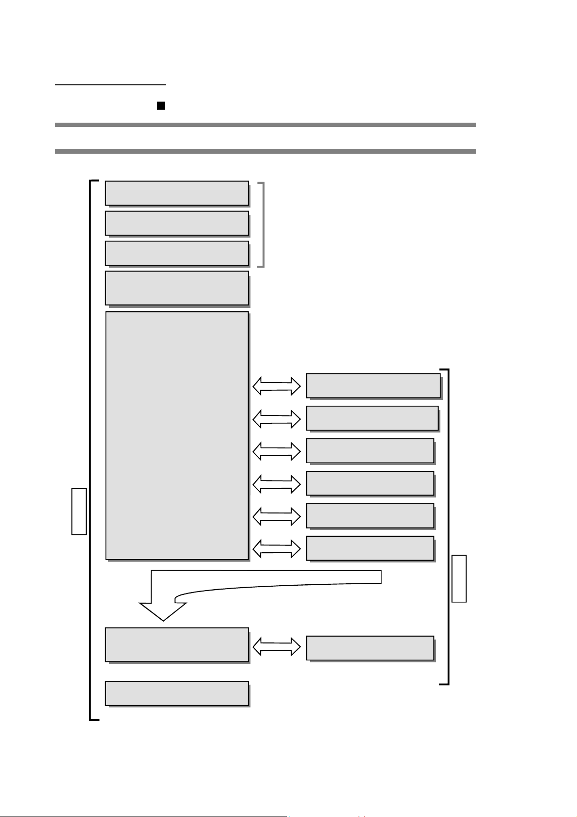
1) 2) 3) 4) 5) Test operation 6) Actual operation
The methods for reading this manual are shown below.
Chapter 1 PRODUCT OUTLINE
Chapter 2 SYSTEM CONFIGURATION
Chapter 3 SPECIFICATIONS AND
FUNCTIONS
Chapter 4 INSTALLATION, WIRING
AND MAINTENANCE OF
THE PRODUCT
Chapter 5 DATA USED FOR
POSITIONING CONTROL
5.1 Types of data
5.2 List of parameters
5.3 List of positioning data
5.4 List of start block data
5.5 List of condition data
5.6 List of monitor data
5.7 List of control data
1) Understand the product functions and specifications,
and design the system.
2) Install and wire the product
3) Set the parameters
4) While referring to lists in "SECTION 2" and "Chapter 5",
set the data required for each control
Chapter 8 ZERO POINT RETURN
CONTROL
Chapter 9 MAIN POSITIONING
CONTROL
Chapter 10
POSITIONING CONTROL
Chapter 11 MANUAL CONTROL
ADVANCED
SECTION 1 PRODUCT SPECIFICATIONS AND HANDLING
Chapter 6
FOR POSITIONING CONTROL
Chapter 7
AND DATA PROCESS
*Understand the data process in the D75P2 as necessary.
SEQUENCE PROGRAM USED
MEMORY CONFIGURATION
Chapter 12 CONTROL AUXILIARY
FUNCTIONS
Chapter 13
5) Create a sequence program for control
Chapter 14 TROUBLESHOOTING
6) Remedies for "Errors" and "Warnings"
COMMON FUNCTIONS
A - 18
SECTION 2 CONTROL DETAILS AND SETTING
Page 21
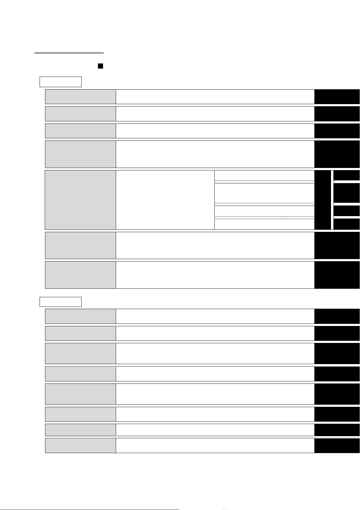
USING THIS MANUAL (3)
The contents of each chapter are shown below.
SECTION 1 PRODUCT SPECIFICATIONS AND HANDLING
1 PRODUCT OUTLINE
2 SYSTEM
CONFIGURATION
3 SPECIFICATIONS
AND FUNCTIONS
4 INSTALLATION,
WIRING AND
MAINTENANCE OF
THE PRODUCT
The basic contents for understanding positioning control using D75P2 are
described.
The devices required for positioning control using D75P2 are described.
The D75P2 functions and performance specifications, etc., are described.
The procedures for installing and wiring the D75P2, the precautions and
maintenance are described.
List of parameters
1
2
3
4
Pr.
List of positioning data
List of start block data
List of condition data
List of monitor data
List of control data
5 DATA USED FOR
POSITIONING
CONTROL
The setting items, setting details and
range, default values, and setting
destination buffer memory address for
the parameters and data required for
positioning control are described.
6 SEQUENCE
PROGRAM USED
FOR POSITIONING
CONTROL
7 MEMORY
CONFIGURATION
AND DATA
PROCESS
SECTION 2 CONTROL DETAILS AND SETTING
8 ZERO POINT
RETURN CONTROL
9 MAIN POSITIONING
CONTROL
10 ADVANCED
POSITIONING
CONTROL
11 MANUAL CONTROL
12 CONTROL
AUXILIARY
FUNCTIONS
13 COMMON
FUNCTIONS
14 TROUBLESHOOTING The errors and warnings detected by the D75P2 are described.
The sequence program required for positioning control is described.
(Create an actual program using this program as a reference.)
The D75P2 memory configuration and data process are described.
(Read this as required.)
The details and settings for zero point return control are described.
The details and examples of settings for "Main positioning control" using the
"Positioning data" are described.
The details and examples of settings for "Advanced positioning control" using
the "Positioning data" are described.
The settings and sequence programs required for JOG operation or manual
pulse generator operation are described.
The settings and sequence programs required for using the auxiliary functions
are described.
The settings and sequence programs required for using the common functions
are described.
APPENDICES
Examples of wiring, a glossary and list of buffer memory addresses are
described. (Read this as required.)
Da.
5
Md.
Cd.
6
7
8
9
10
11
12
13
14
APPENDICES
A - 19
Page 22

GENERIC TERMS AND ABBREVIATIONS
Unless specially noted, the following generic terms and abbreviations are used in this
manual.
Generic term/abbreviation Details of generic term/abbreviation
D75P2 Generic term for positioning module AJ65BT-D75P2-S3 type.
Peripheral device
AD75 software package
Drive unit Abbreviation for pulse input compatible drive unit (servo amplifier, stepping motor).
Manual pulse generator Abbreviation for manual pulse generator (prepared by user).
Data link system Abbreviation for MELSECNET ( ) and MELSECNET/B data link system.
Network system Abbreviation for MELSECNET/10 network system.
I/F Abbreviation for interface.
DOS/V personal computer IBM PC/AT® and compatible DOS/V compliant personal computer.
Personal computer Generic term for DOS/V personal computer.
Workpiece Generic term for moving body such as workpiece and tool, and for various control targets.
CC-Link Abbreviation for Control & Communication Link.
Master station Station that controls remote, local and intelligent device stations in a CC-Link system.
Remote I/O station Remote station that handles only bit data. (AJ65BTB - , AJ65BTC - )
Local station Station that has a CPU and can communicate with the master station and other local stations.
Intelligent device station
Master module Generic term for modules that can be used as the master station.
Cyclic transmission
Transient transmission Function that updates data for specified station at access request of PLC CPU.
RX Remote input.
RY Remote output.
RWw Remote register. (Write area)
RWr Remote register. (Read area)
Generic term for DOS/V personal computer that can run the following "AD75 Software
Package".
Generic term for "SW1IVD-AD75P type positioning module software package" and "GX
Configurator-AP Version 1 (SW0D5C-AD75P-E)."
Slave station in a CC-Link system that can make transient transmission, such as D75P2 or
AJ65BT-R2.
Transmission method that updates contents of remote input/output and remote registers
periodically.
A - 20
Page 23

ENCLOSED PARTS
The D75P2 product configuration is shown below.
Part name Quantity
External device connection connector
(10136-3000VE, Sumitomo 3M)
Connector cover (10336-56 F0-008, Sumitomo 3M) 2
Module (AJ65BT-D75P2-S3) 1
AJ65BT-D75P2-S3 Positioning Module User's Manual
(Hardware)
2
1
A - 21
Page 24

MEMO
A - 22
Page 25

SECTION 1
PRODUCT SPECIFICATIONS AND HANDLING
SECTION 1
SECTION 1 is configured for the following purposes (1) to (5).
(1) To understand the outline of positioning control, and the D75P2 specifications
and functions
(2) To carry out actual work such as installation and wiring
(3) To set parameters and data required for positioning control
(4) To create a sequence program required for positioning control
(5) To understand the memory configuration and data transmission process
Read "SECTION 2" for details on each control.
Chapter 1 PRODUCT OUTLINE ................................................................................... 1- 1 to 1- 20
Chapter 2 SYSTEM CONFIGURATION ....................................................................... 2- 1 to 2- 12
Chapter 3 SPECIFICATIONS AND FUNCTIONS ........................................................ 3- 1 to 3- 43
Chapter 4 INSTALLATION, WIRING AND MAINTENANCE OF THE PRODUCT ..... 4- 1 to 4- 30
Chapter 5 DATA USED FOR POSITIONING CONTROL ............................................ 5- 1 to 5-112
Chapter 6 SEQUENCE PROGRAM USED FOR POSITIONING CONTROL ............. 6- 1 to 6- 66
Chapter 7 MEMORY CONFIGURATION AND DATA PROCESS ............................... 7- 1 to 7- 16
APPENDICES
Page 26

MEMO
Page 27

Chapter 1
2
1
3
4
PRODUCT OUTLINE
The purpose and outline of positioning control using D75P2 are explained in this chapter.
By understanding "What can be done", and "Which procedures to use" beforehand, the
positioning system can be structured smoothly.
5
6
7
1.1 Positioning control ........................................................................................................ 1- 2
1.1.1 Features of D75P2 .......................................................................................... 1- 2
1.1.2 Purpose and applications of positioning control ............................................ 1- 4
1.1.3 Mechanism of positioning control ................................................................... 1- 6
1.1.4 Outline design of positioning system.............................................................. 1- 8
1.1.5 Communicating signals between D75P2 and each module ........................ 1- 10
1.2 Flow of system operation ............................................................................................ 1- 12
1.2.1 Flow of all processes ..................................................................................... 1- 12
1.2.2 Outline of starting ........................................................................................... 1- 14
1.2.3 Outline of stopping ......................................................................................... 1- 16
1.2.4 Outline for restarting ...................................................................................... 1- 17
1.3 Outline of communication ............................................................................................ 1- 1 8
1.3.1 Cyclic transmission ........................................................................................ 1- 19
1.3.2 Transient transmission................................................................................... 1- 20
8
9
10
11
12
13
14
APPENDICES
1 - 1
Page 28

A
1 PRODUCT OUTLINE
1.1 Positioning control
1.1.1 Features of D75P2
MELSEC-
The features of the D75P2 are shown below.
(1) Compatibility with distributed system
The D75P2 can be installed near distributed servo amplifiers and stepping
motors.
(2) Ease of compatibility with absolute position detection system
(a) Connection of an absolute position-compatible servo system provides
compatibility with an absolute position detection system.
(b) Once the zero point position has been established, the axis can return to
the address prior to power-on by absolute position restoration.
(c) In the absolute position detection system, the zero point position can be
established by data setting method zero point return.
This makes the wiring of near-point dogs, etc. unnecessary.
(3) Control by mechanical inputs
External inputs, such as external start, stop, and speed/position changeover,
allow positioning control to be performed without use of sequence programs.
(4) Ample positioning control functions
(a) Various functions required for the positioning system, such as positioning
control to random position, fixed-dimension feed control and uniform speed
control are provided.
1) Up to 600 positioning data items containing the positioning address,
control method and operation pattern, etc., can be set for each axis.
Positioning for each axis is carried out using this positioning data. (2axis interpolation control, and multiple axes using simultaneous start is
possible.)
2) Linear control (2-axis simultaneous execution possible) is possible with
positioning for each axis. This control can carry out independent
positioning with one positioning data item, or can carry out continuous
positioning with continuous execution of multiple positioning data items.
3) With multiple axes positioning, linear interpolation control or circular
interpolation control using two axes is possible. This control can carry
out independent positioning with one positioning data item, or can carry
out positioning with continuous execution of multiple positioning data
items.
(b) The control method designated with each positioning data includes position
control, speed control and speed/position changeover control.
(c) Continuous positioning with multiple positioning data items is possible with
the operation pattern set by the user using positioning data.
With the above multiple positioning data as one block, continuous
positioning of multiple blocks is possible.
1 - 2
Page 29

A
1 PRODUCT OUTLINE
(5) High-speed pulse output and long distance with drive unit
(6) Easy maintenance
MELSEC-
(d) The zero point return control has been strengthened.
1) The near-point dog method (one method), stopper stop method (three
types), and count method (two types) zero point return methods have
been prepared as the "machine zero point return" zero point return
method.
2) To realize zero point return control to the machine zero point from a
random position, the zero point return retry function has been prepared.
(The machine zero point is the position used as the start point for
control such as positioning control. The machine zero point is
established with the machine zero point return in item 1) above.)
(e) Automatic trapezoidal acceleration/deceleration and S-curve
acceleration/deceleration have been prepared as the
acceleration/deceleration methods. The user can select from automatic
trapezoidal acceleration/deceleration or S-curve acceleration/deceleration.
(a) The D75P2 has a differential driver and open collector pulse output
interface.
Connect to either according to the type of drive unit.
(b) When connected to the differential driver, the speed and distance have
been increased.
When connected to differential driver : 400kpps, max. 10m,
When connected to open collector : 200kpps, max. 2m
The maintenance of the D75P2 has been improved with the following matters.
(a) The various data, such as the positioning data and parameters, are stored
on a flash ROM in the D75P2.
This allows the data to be held without a battery.
(b) The error display, machine system input and zero point input state can be
confirmed with the 17-segment display.
(c) The primary diagnosis has been improved by detailing the error details.
(d) Up to 16 history items each for the error and warning information can be
held, so the details of the errors and warnings that have occurred can be
confirmed easily.
1 - 3
Page 30
A
a
1 PRODUCT OUTLINE
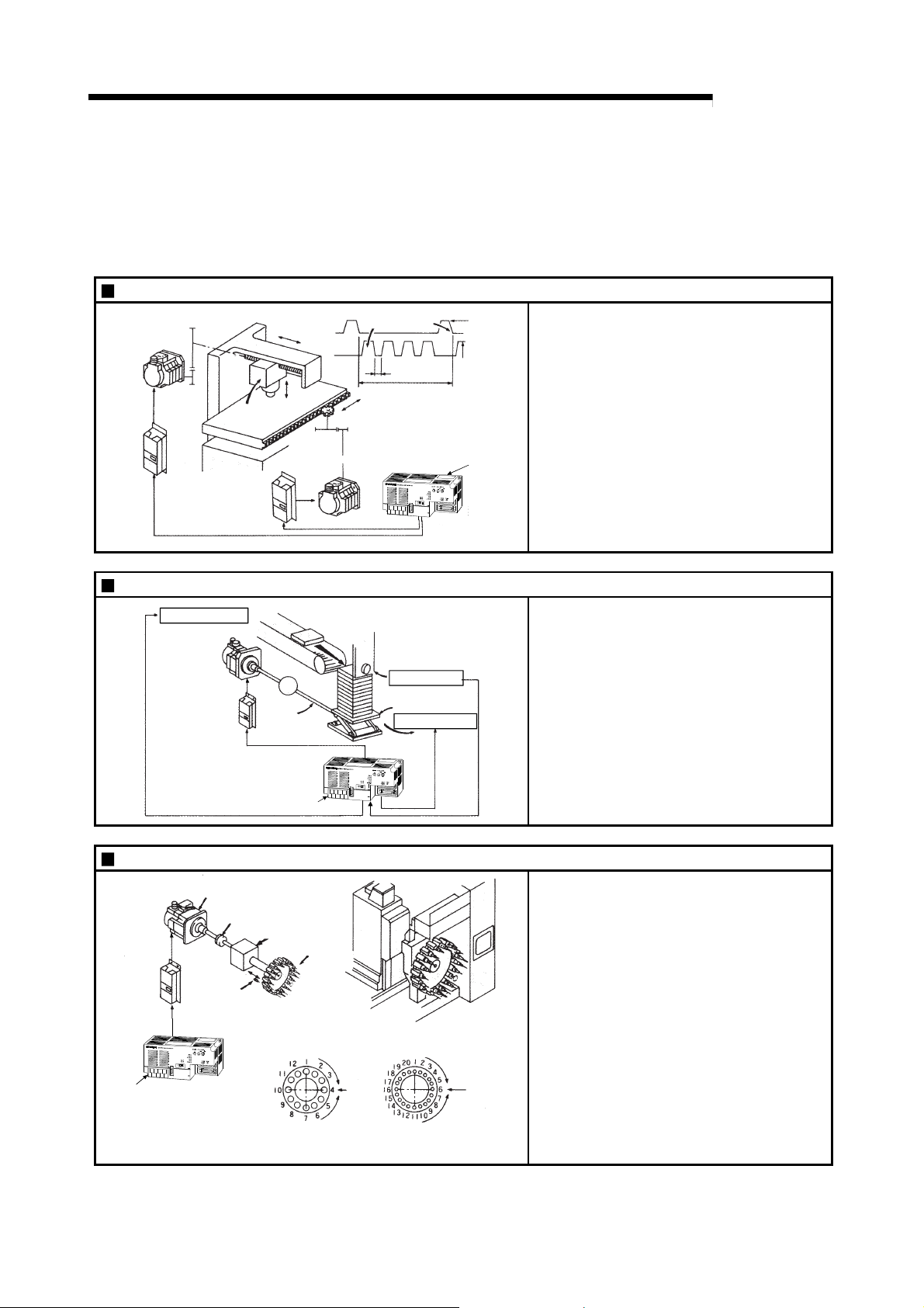
1.1.2 Purpose and applications of positioning control
"Positioning" refers to moving a moving body, such as a workpiece or tool (hereinafter,
generically called "workpiece") at a designated speed, and accurately stopping it at the
target position. The main application examples are shown below.
Punch press (X, Y feed positioning)
Servo
mplifier
Palletizer
Y axis
servomotor
Conveyor control
Servomotor
(with brakes)
Servo amplifier
Gear and ball screw
Press head
Servo
amplifier
Y axis
X axis
servomotor
G
Reduction
gears
Ball screw
(From D75P2)
X axis
Conveyor
320mm
Y axis
X axis
Gear and rack & pinion
160mm
Press
punching
12 s
X axis
Y axis
Position detector
Palletizer
Unloader control
15m/min
(2000r/min)
15m/min
(1875r/min)
D75P2
MELSEC-
To punch insulation material or leather, etc.,
as the same shape at a high yield, positioning
is carried out with the X axis and Y axis
servos.
After positioning the table with the X axis
servo, the press head is positioned with the Y
axis servo, and is then punched with the
press.
When the material type or shape changes, the
press head die is changed, and the positioning
pattern is changed.
Using the servo for one axis, the palletizer is
positioned at a high accuracy.
The amount to lower the palletizer according to
the material thickness is saved.
D75P2
Compact machining center (ATC magazine positioning)
Servomotor
Servo
amplifier
D75P2
Coupling
Positioning
pin
Reduction
gears
ATC tool
magazine
Tool
(12 pcs., 20 pcs.)
Rotation direction
for call ing
11, 12, 1, 2 or 3
Current
value
retrieval
position
Rotation direction
for calling 5, 6, 7, 8, 9 or 10
<No. of tools: 12> <No. of tools: 20>
Rotation direction
for calling
17 to 20, 1 to 5
Current
value
retrieval
position
Rotation direction
for calling 7 to 16
1 - 4
The ATC tool magazine for a compact
machining center is positioned.
The relation of the magazine's current value
and target value is calculated, and positioning
is carried out with forward run or reverse run to
achieve the shortest access time.
Page 31

A
1 PRODUCT OUTLINE
Lifter (Storage of Braun tubes onto aging rack)
B conveyor
Lifter C
Counterweight
Reduction
gears
G1
Servomotor
(with brakes)
conveyor
A conveyor Servo amplifier
Loader
Servomotor
Servo amplifier
Aging rack
G2
Positioning module
D75P2-S3
Index table (High-accuracy indexing of angle)
D75P2
Unloader
Loader/unloader
MELSEC-
During the aging process of braun tubes,
storage onto the rack is carried out by
positioning with the servo.
The up/down positioning of the lifter is carried
out with the 1-axis servo, and the horizontal
position of the aging rack is positioned with the
2-axis servo.
The index table is positioned at a high accuracy
using the 1-axis servo.
Digital switch
Index table
Worm gears
Inner surface grinder
Servomotor
Inverter
AC220V
60Hz
D75P2
Servo
amplifier
Motor
1M
G
Fix the grinding
stone, feed the
workpiece, and grind.
Operation panel
a
b
c
Workpiece
Grinding stone
a. Total feed
d
amount (mm)
b. Finishing
e
feed amount (mm)
c. Compensation
amount (mm)
Detector
Servomotor
Motor
G
1M
Inverter
Servo
amplifier
d. Rough grind ing speed (mm/s)
e. Fine grindi ng
speed ( mm/s)
The grinding of the workpiece's inner surface
is controlled with the servo and inverter.
The rotation of the workpiece is controlled with
the 1-axis inverter, and the rotation of the
grinding stone is controlled with the 2-axis
inverter. The workpiece is fed and ground with
the 3-axis servo.
1 - 5
Page 32
A
1 PRODUCT OUTLINE
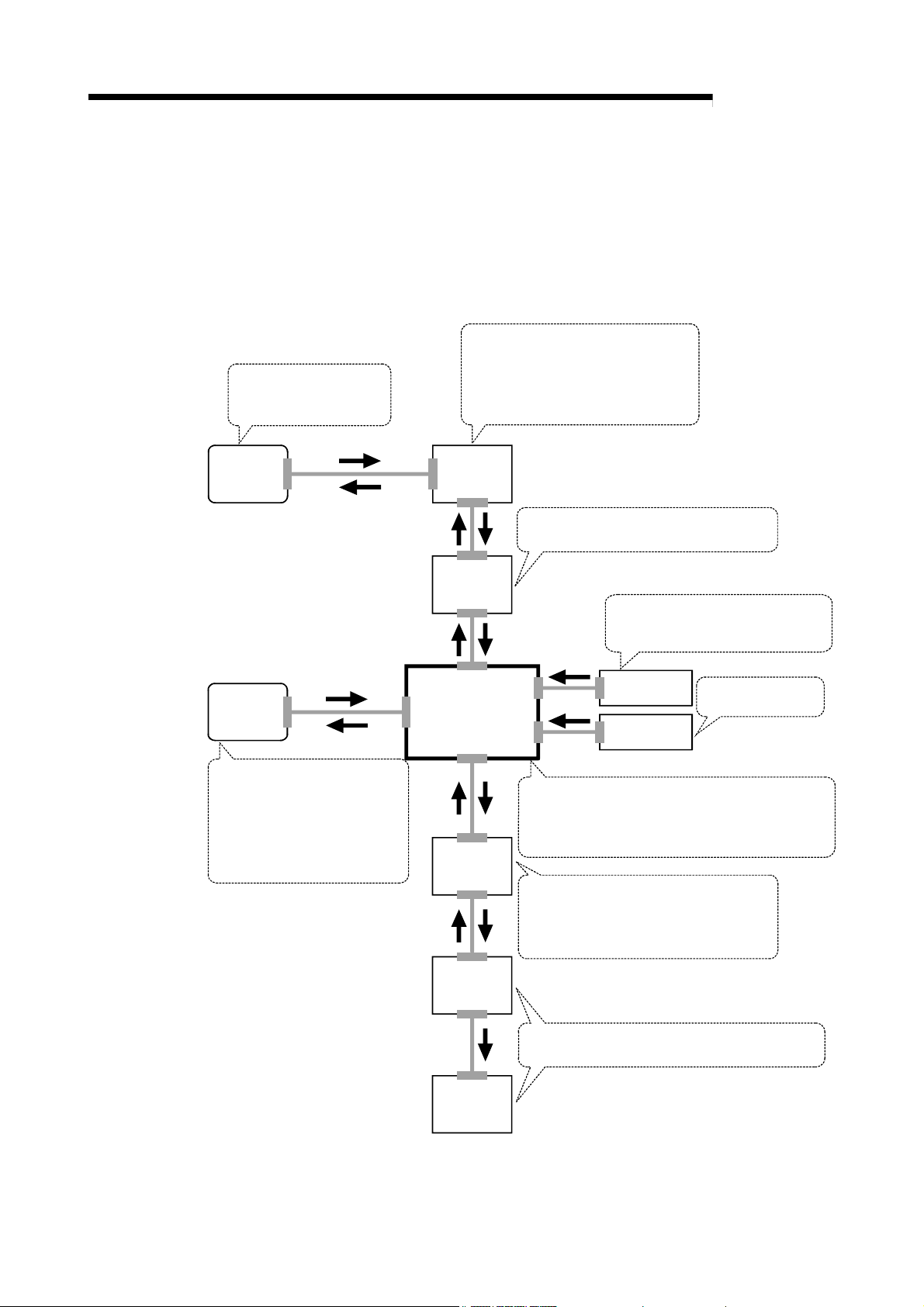
1.1.3 Mechanism of positioning control
Positioning control using the D75P2 is carried out with "pulse signals". (The D75P2 is a
module that generates pulses). In the positioning system using the D75P2, various
software and devices are used for the following roles. The D75P2 realizes complicated
positioning control when it reads in various signals, parameters and data and is
controlled with the PLC CPU.
Creates control order and
conditions as a sequence
program.
GPP function
software
package
Stores the created program.
The D75P2 outputs the start signal and
stop signal following the stored program.
D75P2 errors, etc., are detected.
PLC CPU
MELSEC-
AD75
software
package
Sets the parameters and
positioning data for control.
Outputs the start command for
JOG operation, etc., during test
operation with the test mode.
Monitors the positioning operation.
CC-Link
master/local
module
D75P2 positioning
module
Servo
amplifier
Communicates with the D75P2, using RX as
input and RY as output.
Outputs signals such as the start
signal, stop signal, limit signal and
control changeover signal to the D75P2.
External signal
Manual pulse
generator
Stores the parameter and data.
Outputs pulses to the servo according to the
instructions from the PLC CPU, AD75 software
package, external signals and manual pulse generator.
Receives pulse commands from D75P2,
and drives the motor.
Outputs the drive unit READY signal and
zero point signal to the D75P2.
Issues commands by
transmitting pulses.
Motor
Carries out the actual work according to commands
from the servo.
Workpiece
1 - 6
Page 33

A
1 PRODUCT OUTLINE
The principle of "position control" and "speed control" operation is shown below.
Position control
The total No. of pulses required to move the designated distance is obtained in the
following manner.
Total No. of pulses
required to move
designated distance
When this total No. of pulses is issued from the D75P2 to the servo amplifier, control to
move the designated distance can be executed.
The machine side movement amount when one pulse is issued to the servo amplifier is
called the "movement amount per pulse". This value is the min. value for the workpiece
to move, and is also the electrical positioning precision.
Speed control
The above "total No. of pulses" is an element required for movement distance
control, but when carrying out positioning control or speed control, the speed must
also be controlled.
This "speed" is controlled by the "pulse frequency".
MELSEC-
Designated distance
Movement amount of machine (load)
side when motor rotates once
* The No. of pulses required for the motor to rotate once is the "encoder resolution"
described in the motor catalog specification list.
No. of pulses required for
motor to rotate once
Positioning
module
Speed = Pulse frequency
Movement amount = No. of pulses
Feedback pulses =
Pulses generated by detector
Servo
amplifier
Servomotor
Feedback pulse
Detector
(Pulse
encoder)
Pulse frequency
[pps]
A
ta td
0.4 1.2 0.4
Movement amount t = 2
This area is the total
No. of commanded
pulses.
(s)
Fig. 1.1 Relationship between position control and speed control
POINT
The D75P2 controls the position with the "total No. of pulses", and the speed with
the "pulse frequency".
1 - 7
Page 34

A
1 PRODUCT OUTLINE
1.1.4 Outline design of positioning system
The outline of the positioning system operation and design, using the D75P2, is shown
below.
MELSEC-
PLC CPU
Program
Write,
read,
etc.
Master
module
Buffer
memory
Positioning
module D75P2
RX,
RWr
Set data
RY,
RWw
Write,
read, etc.
· SW1IVD-AD75P-E
· SW0D5C-AD75P-E
· AD75 TU
Forward run
pulse train
Reverse run
pulse train
Deviation
counter
Drive unit
D/A
converter
Speed
command
Interface
Feedback pulse
Servo
amplifier
Servomotor
M
PLG
Fig. 1.2 Outline of the operation of positioning system using D75P2
1) The D75P2 output is a pulse train.
When the pulse train is output, the pulses are cumulated with the deviation
counter. This pulse droop amount is changed into a DC analog voltage by the D/A
converter, and is used as the speed command.
2) Simultaneously with the start of motor rotation by the speed command from the
drive unit, feedback pulses proportional to the speed are generated by the pulse
encoder PLG, and the droop pulses in the deviation counter are subtracted.
The deviation counter maintains a set droop amount and the motor continues
rotating.
3) When the command pulse output from the D75P2 is stopped, the droop pulses in
the deviation counter decreases, and the speed slows. When there are no more
droop pulses, the motor stops.
In other words, the motor rotation speed is proportional to the designated pulse
frequency, and the motor rotation angle is proportional to the No. of output
command pulses.
Thus, if the movement amount per pulse is specified, the motor can be fed to a
position proportional to the No. of pulses in the pulse train. The pulse frequency
will be the motor speed (feedrate).
4) As shown below, the pulse train is rough during motor acceleration, and is dense
at the full speed. During deceleration, the pulse train becomes rougher, and
finally the pulse reaches 0. The motor stops with a slight delay in respect to the
command pulse.
This time difference is required to ensure the stopping precision, and is called the
stop settling time.
1 - 8
Page 35

A
r
r
1 PRODUCT OUTLINE
Speed V Pulse droop
amount
Pulse
distribution
Servomotor
speed
MELSEC-
Acceleration
Pulse train Rough Dense Rough
Deceleration
Time t
Stop
settling time
Fig. 1.3 D75P2 output pulses
A : Movement amount per pulse (mm/pulse)
Vs : Command pulse frequency (pulse/s)
Pulse encode
(PLG)
Servomotor
V
Workpiece
Worm gea
R
Table
P0
L
P
n : Pulse encoder resolution (pulse/rev)
L : Worm gear lead (mm/rev)
R : Deceleration ratio
V : Movable section speed (mm/s)
N : Motor speed (r/min)
K : Position loop gain (1/s)
: Deviation counter droop pulse amount
P0 : Zero point (pulse)
P : Address (pulse)
Fig. 1.4 System using worm gears
(1)
Movement amount per pulse
R
L
n
[mm/pulse]
A =
(2) Command pulse frequency
Vs =
V
A
[pulse/s]
(3) Deviation counter droop pulse amount
Vs
=
K
[pulse]
The movement amount per pulse is indicated with (1), and the [No. of output pulses]
[
movement amount per pulse] is the movement amount. The command pulse frequency is
calculated with (2) using the movable section speed and
movement amount per pulse.
The relation of the command pulse frequency and deviation counter droop pulses is
shown in (3).
As the positioning command
unit, (mm), (inch), (degree) or (pulse) can be selected
independently for the 1 to 2 axes of the D75P2.
Thus, if the data such as the movement amount per pulse, acceleration/deceleration
time, positioning speed, and positioning address are set to match the positioning
command unit, the operation will be carried out within the D75P2 for the target
positioning address. The pulse train will be output, and positioning will be executed.
1 - 9
Page 36
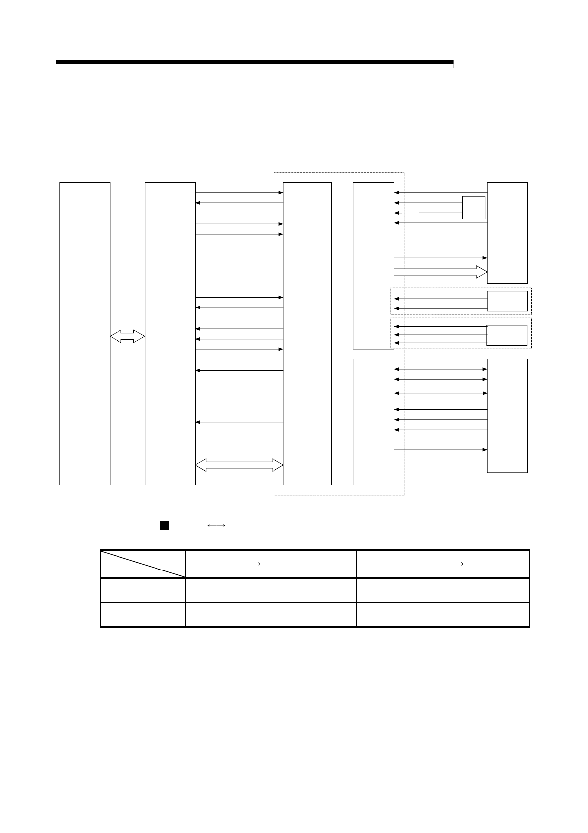
A
1 PRODUCT OUTLINE
1.1.5 Communicating signals between D75P2 and each module
The outline of the signal communication between the D75P2 and PLC CPU, peripheral
device and drive unit, etc., is shown below.
PLC CPU
Master module
RX(n+7)B
RXn0
RY(n+1)6,
RY(n+1)8
RY(n+1)7,
RY(n+1)9
Remote station READY signal
D75P2 READY signal
Forward run JOG start signal
Reverse run JOG start signal
D75P2
External
interface
MELSEC-
Drive unit READY signal
Upper/lower limit signal
Near-point dog signal
Zero point signal
Deviation counter clear
Pulse train
External
signal
Drive unit
Write/read
RY(n+1)0,
RY(n+1)1
RXn7, RXn8
RXn4, RXn5
RXn1, RXn2
RY(n+1)3,
RY(n+1)4
RXnD, RXnE
RXnA, RXnB
Positioning start signal
Positioning complete signal
BUSY signal
Start complete signal
Axis stop signal
M code ON signal
Error detection signal
Data write/read
Interface with
master module
Peripheral
device
interface
Manual pulse generator A-phase
Manual pulse generator B-phase
Speed/position changeover signal
Stop signal
External start signal
Parameter write/read
Positioning data write/read
Positioning start information
write/read
Zero point return operation
(test)
JOG operation (test)
Positioning operation (test)
Operation monitor
Manual pulse
generator
External
signal
Peripheral
device
D75P2 Master module
Communication
Control signal *
Data (read/write)
* Refer to the section "3.4 Specifications of input/output signals with master module" for details.
The D75P2 and Master module communicate the following data via the base unit.
Direction
Signal indicating D75P2 state, such as
D75P2 READY signal, BUSY signal.
Parameter, positioning data, positioning
start information, monitor data, control data
D75P2
Master module Master module D75P2
Signal related to commands such as
various start signals, stop signals, etc.
Parameter, positioning data, positioning
start information, control data
1 - 10
Page 37
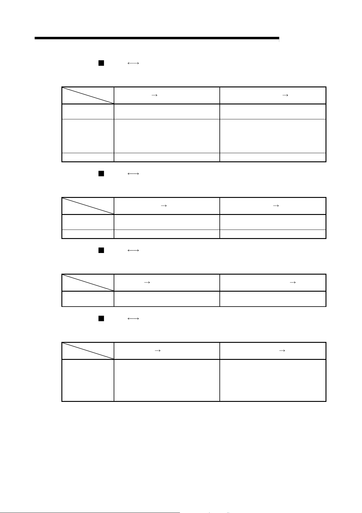
A
1 PRODUCT OUTLINE
D75P2 Peripheral device
The D75P2 and peripheral device communicate the following data via the peripheral
Communication
Data (read/write)
Test operation –
Operation monitor Monitor data –
device connection connector.
Direction
D75P2 Drive unit
The D75P2 and drive unit communicate the following data via the external device
Communication
Control signal
Pulse train Pulse train output –
connection connector.
Direction
D75P2 Manual pulse generator
The D75P2 and manual pulse generator communicate the following data via the
Communication
Pulse signal –
external device connection connector.
Direction
D75P2 External signal
The D75P2 and external signal communicate the following data via the external
Communication
Control signal –
device connection connector.
Direction
D75P2
Parameter, positioning data, positioning
start information
Signals related to commands such as
deviation counter clear signal
D75P2
D75P2
Peripheral device Peripheral device D75P2
D75P2
Drive unit Drive unit D75P2
Manual pulse generator Manual pulse generator D75P2
External signal External signal D75P2
MELSEC-
Parameter, positioning data, positioning
start information
Zero point return control start command
Positioning control start command
JOG operation start command
Manual pulse generator operation
enable/disable command
Signals indicating drive unit state such as
drive unit READY signal
Manual pulse generator A-phase, manual
pulse generator B-phase
Signals from detector such as near-point
dog signal, upper/lower limit signal, zero
point signal
Control signals from external device such
as stop signal, external start signal,
speed/position changeover signal
1 - 11
Page 38

A
1 PRODUCT OUTLINE
1.2 Flow of system operation
1.2.1 Flow of all processes
Design
The positioning control processes, using the D75P2, are shown below.
AD75 software
package
1)
Understand the functions and performance, and determine the positioning operation method
(system design)
D75P2
2)
Installation, wiring, single module test
Servo, etc.
PLC CPU/
master module
MELSEC-
GPP function software package
Preparation
Operation
3) 4)
Setting of the:
· Parameters
· Positioning data
· Start block data
· Condition data
Writing of setting data
7) 8)
Monitoring with
test operation,
and debugging
of setting data
Monitor
9)
5) 6)
Connection confirmation
Test operation
Actual operation
Creation of sequence
program for operation
Writing of program
Monitoring and
debugging of
operation
program
Monitor
10)
Maintenance
11)
Maintenance
Disposal
1 - 12
Page 39

A
1 PRODUCT OUTLINE
MELSEC-
Details Reference
Understand the product functions and usage methods, the configuration devices
1)
and specifications required for positioning control, and design the system.
Install the D75P2 onto the DIN rail or enclosure surface, wire the D75P2 and
2)
external connection devices (drive unit, etc.), and connect the D75P2 and
peripheral devices. Check that the D75P2 operates correctly. (Single module test)
Using the D75P2 software package, set the parameters, positioning data, start
3)
block data and condition data required for the positioning control to be executed.
Using the GPP function software package, create the sequence program required
for positioning operation. (When not using the AD75 software package, also create
4)
the sequence program for setting data.)
Write the parameters and positioning data, etc., created with the AD75 software
5)
package into the D75P2.
Using the GPP function software package, write the created sequence program into
the PLC CPU. (When not using the AD75 software package, also write in the
6)
sequence program for setting data.)
Carry out test operation and adjustments in the test mode to check the connection
with the D75P2 and external connection device, and to confirm that the designated
7)
positioning operation is executed correctly. (Debug the set "parameters" and
"positioning data", etc.)
Carry out test operation and adjustment to confirm that the designated positioning
8)
operation is executed correctly. (Debug the created sequence program. When not
using the AD75 software package, also debug the set data.
Actually operate the positioning operation. At this time, monitor the operation state
9)
as required. If an error or warning occurs, remedy.
10) Service the D75P2 as required.
11) Dispose of the D75P2.
The following work is carried out with the processes shown on the left page.
Chapter 1
Chapter 2
Chapter 3
Chapter 8 to Chapter 13
Chapter 4
Chapter 5
Chapter 8 to Chapter 13
AD75 Software Package
Operating Manual
Chapter 6
GPP Function Software
Package Operating Manual
Chapter 7
AD75 Software Package
Operating Manual
Chapter 7
GPP Function Software
Package Operating Manual
AD75 Software Package
Operating Manual
GPP Function Software
Package Operating Manual
Chapter 5
Chapter 14
AD75 Software Package
Operating Manual
GPP Function Software
Package Operating Manual
Chapter 4
Chapter 4
1 - 13
Page 40

A
1 PRODUCT OUTLINE
1.2.2 Outline of starting
The outline for starting each control is shown with the following flowchart.
* It is assumed that each module is installed, and the required system configuration,
etc., has been prepared.
Flow of starting
MELSEC-
Preparation
Control
functions
Positioning
parameters
Zero point return
parameters
Positioning
data
Positioning
start informa tion
Control data
Installation and connection of master module and D75P2
Setting of master module and D75P2 (transmission speed, station number, etc.)
Main positioning control
·Position control
·Speed control
·Speed/position
changeover control
·Other control
Advanced positioning control
·Block start
·Condition start
·Wait start
·Simultaneous start
·St op
·Re pe titiv e st art
·Machine zero point return control
Set the positioning parameters.
Set the zero point return parameters.
Set the positioning data.
)
to
Da.1)Da.9
Set the positioning
start information.
)
Da.10
Set the positioning start No. (RWwm, RWwm+8)
to
Da.18
)
Set the positioning
starting point No.
)
)
Cd.31
Zero point return
control
·
Data setting method
zero poin t return control
·High-speed zero
point return control
)
)
to
Pr.45)Pr.58
Manual control
·JOG operation
·Manual pulse generator operation
)
to
Pr.1
Pr.44
Set the JOG speed
RWwm+6 to 7,
RWwm+14 to 15
Set the manual pulse generator enable flag to "ON".
(RY(n+1)9, RY(n+4)9)
Set the manual pulse generator
Start signal
Control start
Input the start signal.
Method (1) Turn ON the D75P2 start signal from the
PLC CPU
Method (2) Turn the D75P2 external start signal ON
1 pulse input magnification.
Turn the D75P2 JOG
start signal ON from
the PLC CPU
)
)
Cd.23
Operate the
manual pulse
generator
Operation
Control end
Stop
1 - 14
Page 41

A
1 PRODUCT OUTLINE
Setting method
: Indicates the sequence program that must be created.
MELSEC-
<AD75 software package>
Set with AD75 software package
* Set the parameter and data for executing this function,
and the auxiliary functions that need to be set beforehand.
<GPP function software package>
Create sequence program for
executing main function
* Create sequence program for
outputting control signals, such
as start signal, to D75P2.
Operation sequence program PLC CPU
<GPP function software package>
· Clock data setting
· Speed change
· Current value change
· Torque limit
· Restart, etc.
Create a sequence
program for the
auxiliary functions.
Write
Write
D75P2
1 - 15
Page 42

A
1 PRODUCT OUTLINE
1.2.3 Outline of stopping
MELSEC-
Forced stop
Fatal stop
(Stop group 1)
Emergency
stop
(Stop group 2)
Relatively safe
stop
(Stop group 3)
Intentional stop
(Stop group 3)
Stop cause
Drive unit
READY signal
OFF
Hardware stroke
limit upper/lower
limit error
occurrence
Software stroke
limit upper/lower
limit error
occurrence
Remote station
READY signal
OFF
"Stop" input from
peripheral device
Axis error
detection (Error
other than stop
group 1 or 2)
Error in test
mode
"Stop signal" ON
from external
source
"Axis stop signal"
ON from PLC
CPU
Each control is stopped in the following cases.
(1) When each control is completed normally.
(2) When the drive unit READY signal is turned OFF.
(3) When the data link of CC-Link stops.
(4) When Initial data setting request (RY(n+7)9) turns ON and Remote station READY
(RX(n+7)B) turns OFF.
(5) When an error occurs in the D75P2.
(6) When control is intentionally stopped (Stop signal from master module turned ON,
stop from peripheral device, etc.)
The outline for the stopping process in these cases is shown below. (Excluding (1) for
normal stopping.)
Stop process
Zero point return
control
HighMachine
zero point
return
control
Immediate stop
Deceleration stop/sudden stop
(Select with Pr.38 )
Deceleration stop/sudden stop
(Select with
Deceleration stop/sudden stop
(Select with
speed
zero
point
return
control
Main
positioning
control
Pr.39 )
Pr.40 )
Advanced
positioning
control
JOG
operation
Manual control
Manual
pulse
generator
operation
Immediate
stop
Deceleration stop
Deceleration stop
Deceleration stop
Stop
axis
Each
axis
Each
axis
Each
axis
All
axes
Each
axis
Each
axis
Axis
operation
status after
stopping
(RWrn+7,
RWrn+15)
During
error
During
error
During
error
During
error
When
stopped
(While
waiting)
1 - 16
Page 43

A
4
1 PRODUCT OUTLINE
1.2.4 Outline for restarting
When a stop cause has occurred during operation with position control causing the
axis to stop, positioning to the end point of the positioning data can be restarted from
the stopped position by using restart command [RY(n+2)5, RY(n+4)5].
When "Restart command [RY(n+2)5, RY(n+4)5]" is ON
(1) If the "Axis operation status (RWrn+7, RWrn+15)" is stopped, positioning to
(2) When "Axis operation status (RWrn+7, RWrn+15)" is not stopped, the warning
[Example for incremental method]
The restart operation when the axis 1 movement amount is 300, and the axis 2
movement amount is 600 is shown below.
Axis 1
MELSEC-
the end point of the positioning data will be restarted from the stopped position
regardless of the absolute method or incremental method.
"restart not possible" (warning code: 104) will be applied, and the restart
command will be ignored.
Axis 1
Stop position due to stop cause
00
Start point
address
200
100
100 300 700
Designated end
point position
Axis 2
Restart
Stop position due to stop cause
400
200
100
300 700
100
Stop position
after restart
Operation
during restart
Axis 2
Reference
If the positioning start signal [RY(n+1)0, [RY(n+1)1]/external start signal is turned
ON while the "Axis operation status (RWrn+7, RWrn+15)" is waiting or stopped,
positioning will be restarted from the start of the positioning start data regardless of
the absolute method or incremental method.
(Same as normal positioning.)
[Example for incremental method]
The positioning start operation when the axis 1 movement amount is 300 and the
axis 2 movement amount is 600 is shown below.
Axis 1
Stop position due to stop cause
400
Start point
address
200
100
100 300 700
Designated
end point
position
Positioning
start
Axis 2
Axis 1
Stop position due to stop cause
500
200
100
300 900
100
Stop position
after start
Operation during positioning
start
Axis 2
1 - 17
Page 44

A
1 PRODUCT OUTLINE
1.3 Outline of communication
For communication between the D75P2 and master module, the two different
transmission formats, cyclic transmission and transient transmission, are used.
When AJ61BT11 or A1SJ61BT11 is used
MELSEC-
PLC CPU
Read/write with
FROM/TO
command
Automatic refresh
with dedicated
command
Master module
Cyclic transmission
Transient
transmission
D75P2
Remote
input/output
Remote registers
Buffer memory
Fig. 1.5 Outline of communication (When AJ61BT11 or A1SJ61BT11 is used)
When a module other than the AJ61QBT11 or A1SJ61QBT11 is used
D75P2
PLC CPU
Automatic refresh
Master module
Cyclic transmission
Transient
transmission
Remote
input/output
Remote registers
Buffer memory
Fig. 1.6 Outline of communication (When a module other than the AJ61QBT11 or A1SJ61QBT11
is used)
1 - 18
Page 45

A
1 PRODUCT OUTLINE
1.3.1 Cyclic transmission
MELSEC-
This section explains cyclic transmission between the D75P2 and master module.
PLC CPU Master module
Buffer memory
Remote input
(RX)
3) 4)
5) 6)
8) 7)
Remote output
(RY)
Remote register
(RWw)
Remote register
(RWr)
1)2)
Link scan
Link scan
Link scan
Link scan
D75P2
Remote input
(RX)
Remote output
(RY)
Remote register
(RWw)
Remote register
(RWr)
Fig. 1.7 Cyclic transmission
(1) Remote input (RX)
1) The data of the remote input (RX) of the D75P2 are stored into the buffer
memory of the master module every link scan.
2) The input data stored in the master module are imported to the PLC CPU by
the FROM command or automatic refresh.
(2) Remote output (RY)
3) The data of the remote output (RY) of the D75P2 are written to the buffer
memory of the master module by the TO command or automatic refresh.
4) The output data stored in the master module are sent to the D75P2 every link
scan.
(3) Remote register (RWw)
5) The data of the remote register (RWw) of the D75P2 are written to the buffer
memory of the master module by the TO command or automatic refresh.
6) The transmission data stored in the master module are sent to the D75P2
every link scan.
(4) Remote register (RWr)
7) The data of the remote register (RWr) of the D75P2 are stored into the buffer
memory of the master module every link scan.
8) The reception data stored in the master module are imported to the PLC CPU
by the FROM command or automatic refresh.
1 - 19
Page 46

A
1 PRODUCT OUTLINE
1.3.2 Transient transmission
This section explains transient transmission between the D75P2 and master module.
When FROM/TO commands are used
MELSEC-
PLC CPU Master module
1)
4)
Transmission/reception area of station No. 1
Buffer memory
(Transmission/reception
area)
Transmission area
Reception area
Transmission/
reception area for
station No. 2
:
D75P2 (Station No. 1)
2)
3)
Buffer memory
Fig. 1.8 Transient transmission (When FROM/TO commands are used)
1) Data (control data + transmission data) are stored into the transmission area
of the master module.
2) When the intelligent device station access request signal (RY(n+7)E) is turned
ON, the data stored in the transmission area are stored into the D75P2.
3) When the intelligent device station access complete signal (RX(n+7)E) is
turned ON, a response is stored into the reception area of the master module.
4) Data are read from the reception area of the master module.
When dedicated commands (RIRD, RIWT) are used
PLC CPU Master module
Buffer memory
(Transmission/reception
1)
2)
Transmission/reception area of station No. 1
area)
Transmission area
Reception area
Transmission/
reception area for
station No. 2
:
Transient
transmission
D75P2 (Station No. 1)
Buffer memory
Fig. 1.9 Transient transmission (When dedicated commands are used)
1) When data (control data + transmission data) are stored into the word device
and the dedicated command is executed, the transmission data are stored into
the D75P2.
2) A response is stored into the specified word device.
1 - 20
Page 47

Chapter 2
2
1
3
4
SYSTEM CONFIGURATION
In this chapter, the general image of the system configuration of the positioning control
using D75P2, the configuration devices, applicable CPU module and the precautions of
configuring the system are explained.
Prepare the required configuration devices to match the positioning control system.
5
6
7
2.1 General image of system ............................................................................................. 2- 2
2.2 List of configuration devices ......................................................................................... 2- 4
2.3 Applicable system ......................................................................................................... 2- 6
2.4 Precautions for use....................................................................................................... 2- 8
8
9
10
11
12
13
14
Appendices
2 - 1
Page 48

A
2 SYSTEM CONFIGURATION
2.1 General image of system
The general image of the system, including the D75P2, PLC CPU and peripheral
devices is shown below.
(The Nos. in the illustration refer to the "No." in section "2.2 List of configuration
devices".
MELSEC-
Extension
cable
Extension
system
CPU module
Main base unit
CC-Link
master/local
module
CC-Link
dedicated cable
1
Conversion cable
5
1
*
I/O module
D75P2
RS-422 cable
6
Converter
2
*
RS-232 cable
6
REMARK
*1 Refer to section "2.3 Applicable system" for the CC-Link master/local module that
can be used.
2
*
Refer to the AD75 Software Package Operating manual.
2 - 2
Page 49

A
2 SYSTEM CONFIGURATION
MELSEC-
7
Peripheral
device
Cable
9810
AD75TU
4
Drive
unit
Manual pulse generator
Machine system input (switch)
· Near-point dog
· Limit switch
· External start signal
· Speed/position
changeover signal
· Stop signal
AD75 software package
2
Motor
SW1IVD
3
Personal
computer
Either of 2 and 4 is required to use the D75P2.
(Refer to the AD75 Software Package
Operating Manual for details.)
-AD75P-E
SW0D5C
-AD75P-E
2 - 3
Page 50

A
2 SYSTEM CONFIGURATION
2.2 List of configuration devices
MELSEC-
No. Part name Type Remarks
1 Positioning module
AD75 software
2
package
3 Personal computer
4 Teaching unit
5 Conversion cable
Connection cable
6
(converter)
7 Drive unit – (Prepared by user)
Manual pulse
8
generator
Connection cable
9
(dedicated)
Connection cable
10
(prepared by user)
The positioning system using the D75P2 is configured of the following devices.
AJ65BT-D75P2S3
SW1IVD-AD75P-E
SW0D5C-AD75P-E For details, refer to the GX Configurator-AP Operating Manual.
DOS/V personal
computer
AD75TU Ver. D
or more
A1SD75-C01H
A1SD75-C01HA
–
–
AD75C20SNH*
AD75C20SNJ2*2
AD75C20SC For MR-C
–
DOS/V personal computer software package*
(Prepared by user)
Refer to the AD75 Software Package Operating Manual for details.
Unit for setting, monitoring and testing the D75P2 parameters and
positioning data.
Length 30cm Cable for connecting RS-422 cable and D75P2.
RS-232 cable for connecting D75P2 with DOS/V personal computer, and
RS-232/RS-422 converter. (Prepared by user)
Refer to the AD75 Software Package Operating Manual for details.
(Prepared by user)
Recommended: MR-HDP01 (Mitsubishi Electric)
2
For MR-H
For MR-J2/J2S-A
Cable for connecting D75P2 with drive unit, manual pulse generator or
machine system input signal. (Prepared by user)
Refer to manual of connected device.
Cable for connecting D75P2 with drive unit, manual
pulse generator or machine system input signal.
–
1
Compatible as AD75P2-S3.
*
2
Compatible with absolute position detection system.
*
Important
To use the D75P2, either the "AD75 software package" or "Teaching unit" is required.
1
2 - 4
Page 51

A
2 SYSTEM CONFIGURATION
Specifications list of recommended manual pulse generator
Item Specifications
Model name MR-HDP01
Pulse resolution 25pulse/rev (100 pulse/rev after magnification by 4)
Output method
Power supply voltage 4.5 to 13.2VDC
Current consumption 60mA
Life time 100 revolutions (at 200r/min)
Permitted axial loads
Operation temperature -10 to 60 (14 to 140 )
Weight 0.4 (0.88) [kg(lb)]
Number of max. revolution Instantaneous Max. 600r/min. normal 200r/min
Pulse signal status 2 signals : A phase, B phase, 90 phase difference
Friction torque 0.1N/m (at 20 (68 ))
MELSEC-
Voltage-output (power supply voltage -1V or more),
Output current = Max. 20mA
Radial load : Max. 19.6N
Thrust load : Max. 9.8N
2 - 5
Page 52
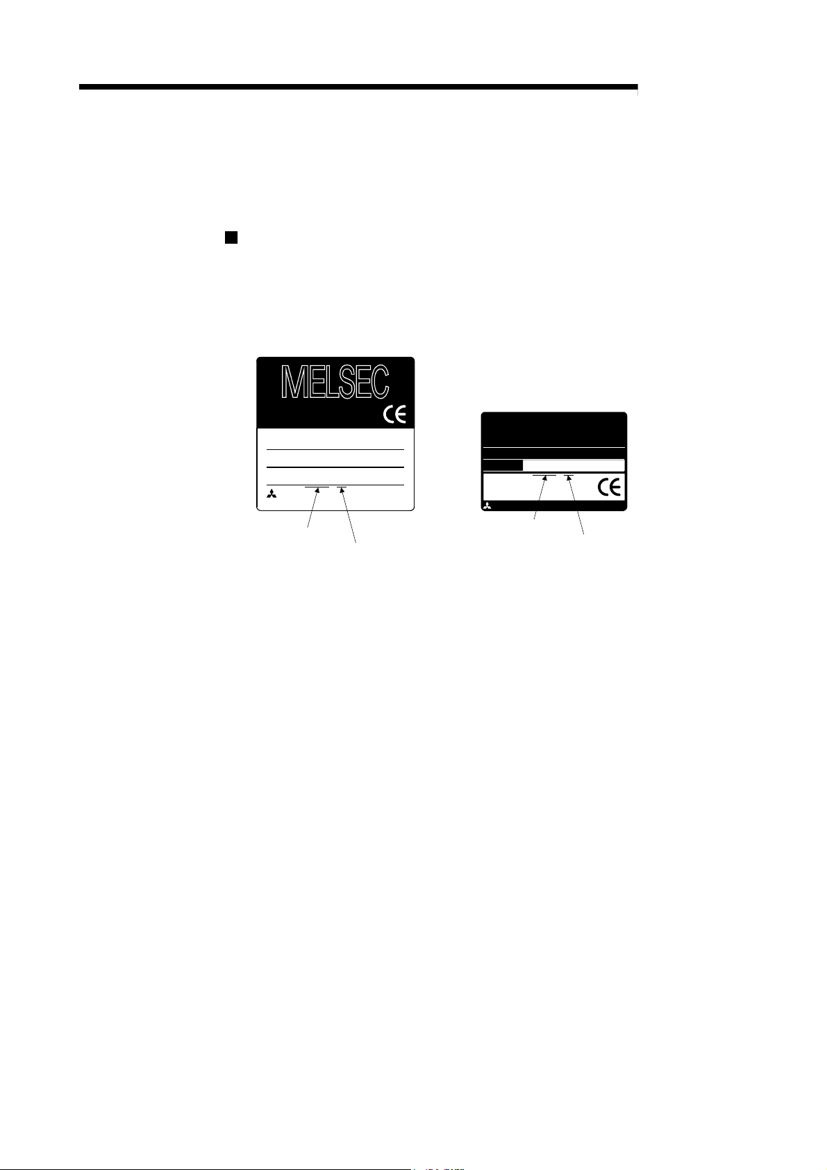
A
2 SYSTEM CONFIGURATION
2.3 Applicable system
This section explains the CC-Link system master modules that can use the D75P2 and
the PLC CPUs that can use the CC-Link dedicated commands.
About the master modules that can use the D75P2
(1) When AJ61BT11, A1SJ61BT11, AJ61QBT11 or A1SJ61QBT11 is
used
Use the master module whose rating plate has the following designation (9707B
or later) in the DATE field.
PROGRAMMABLE CONTROLLER
9707 B
DATE
MITSUBISHI ELECTRIC CORPORATION JAPAN
BD992D013H01
MITSUBISHI
CPU UNIT
A2USHCPU-S1
MODEL
MAX 30kSTEP
DATE
9707 B
MITSUBISHI ELECTRIC BD992D008H38
MELSEC-
Year and month
of manufacture
Function
version
Fig. 2.1 Rating plates of master modules
(2) When QJ61BT11N is used
There are no restrictions.
Year and month
of manufacture
Function
version
2 - 6
Page 53

A
2 SYSTEM CONFIGURATION
PLC CPUs that can use the CC-Link dedicated commands
The PLC CPUs that can use the CC-Link dedicated commands are the following
models.
ACPU
QnACPU
QCPU (A mode)
QCPU (Q mode)
LCPU
RCPU
1
For the module of software version K (manufactured in August, 1998) or later,
*
only the RRPA (automatic refresh) command can be used.
2
For the module of software version A (manufactured in August, 1998) or later,
*
only the RRPA (automatic refresh) command can be used.
MELSEC-
A1SHCPU, A1SJHCPU, A2SHCPU
A2UCPU, A2UCPU-S1, A3UCPU, A4UCPU (Software version Q
(manufactured in July, 1999) or later) *
A2USCPU, A2USCPU-S1 (Software version E (manufactured in July,
1999) or later) *
Q2ACPU, Q2ACPU-S1, Q3ACPU, Q4ACPU, Q2ASCPU, Q2ASCPU-
S1, Q2ASHCPU, Q2ASHCPU-S1 (Function version B or later)
Q02CPU-A, Q02HCPU-A, Q06HCPU-A
Q00JCPU, Q00UJCPU, Q00CPU, Q00UCPU, Q01CPU, Q01UCPU,
Q02CPU, Q02HCPU, Q02PHCPU, Q02UCPU, Q03UDCPU,
Q03UDECPU, Q03UDVCPU, Q04UDHCPU, Q04UDEHCPU,
Q04UDVCPU, Q06HCPU, Q06PHCPU, Q06UDHCPU, Q06UDEHCPU,
Q06UDVCPU, Q10UDHCPU, Q10UDEHCPU, Q12HCPU, Q12PHCPU,
Q12PRHCPU, Q13UDHCPU, Q13UDEHCPU, Q13UDVCPU,
Q20UDHCPU, Q20UDEHCPU, Q25HCPU, Q25PHCPU, Q25PRHCPU,
Q26UDHCPU, Q26UDEHCPU, Q26UDVCPU, Q50UDEHCPU,
100UDEHCPU
L02SCPU, L02SCPU-P, L02CPU, L02CPU-P, L06CPU, L06CPU-P,
L26CPU, L26CPU-P, L26CPU-BT, L26CPU-PBT
R04CPU, R08CPU, R16CPU, R32CPU, R120CPU
2
1
2 - 7
Page 54

A
2 SYSTEM CONFIGURATION
2.4 Precautions for use
Precautions for use of D75P2
(1) Necessity of AD75 Software Package
When using the D75P2, preset the positioning data to the D75P2 using the AD75
Software Package.
(2) About D75P2 functions
The D75P2 has the basic functions (functions indicated in (a)) that can be
achieved by use of cyclic transmission and the functions (functions indicated in
(b)) that can be achieved by use of transient transmission.
Since the functions that can be achieved by use of transient transmission require
access to the D75P2 buffer memory, they are more complicated in sequence
program and further take longer processing time than the basic functions that can
be achieved by use of cyclic transmission.
It is recommended to use them in applications that will not require fast
processing.
The following gives the "functions that can be achieved by cyclic transmission
only" and the "functions that require transient transmission".
* Refer to section "1.3 Outline of communication" for cyclic transmission and
transient transmission.
(a) Functions that can be achieved by cyclic transmission only
The following gives the functions that can be achieved by use of cyclic
transmission only.
Among the D75P2 functions, it is recommended to use the following
functions (main and auxiliary functions) only.
Zero point return control
Main positioning control
Main functions
Advanced positioning control
*2
Manual control
MELSEC-
Function Reference
Machine zero point return control Section 8.2
Data setting method zero point return control Section 8.3
High-speed zero point return control Section 8.4
1-axis linear control Section 9.2.2
2-axis linear interpolation control Section 9.2.3
1-axis fixed-dimension feed control Section 9.2.4
Position control
Speed control Section 9.2.8
Speed/position changeover control *1
Other control
Block start
Condition start
Wait start
Simultaneous start
Stop
Repeated start (FOR loop)
Repeated start (FOR condition)
Manual pulse generator operation *
JOG operation Section 11.2
2-axis fixed-dimension feed control
(interpolation)
2-axis circular interpolation control
Current value change Section 9.2.10
JUMP command Section 9.2.11
3
Section 9.2.5
Section 9.2.6
Section 9.2.7
Section 9.2.9
Section 10.3
Section 11.3
2 - 8
Page 55

A
2 SYSTEM CONFIGURATION
MELSEC-
1
*
Limited to the case where "
Cd. 21
Speed/position changeover control
movement amount change register" and " Cd. 36 Speed/position changeover
control (ABS mode) function valid flag" is not set.
2
*
Limited to the case where " Cd. 31 Positioning starting point number" is used
as "0 (default value)".
3
Limited to the case where " Cd. 23 Manual pulse generator 1 pulse input
*
magnification" is used as "1 time (default value)".
Function Reference
Functions characteristic to machine
zero point return
Functions that compensate control
Functions that limit control
Auxiliary functions
Functions that change control details
Absolute position restoration function Section 12.6
Other functions
Common function LED display function Section 13.4
Zero point return retry function Section 12.2.1
Zero point shift function Section 12.2.2
Backlash compensation function Section 12.3.1
Electronic gear function Section 12.3.2
Near pass mode function Section 12.3.3
Speed limit function Section 12.4.1
Software stroke limit function
Hardware stroke limit function
Speed change function Section 12.5.1
Override function Section 12.5.2
M code output function Section 12.7.3
Command in-position function Section 12.7.5
Stepping motor mode function Section 12.7.6
Acceleration/deceleration processing function Section 12.7.7
Indirectly specification function Section 12.7.8
Section 12.4.3
Section 12.4.4
(b) Functions that require transient transmission (Use them after
examination of the following restrictions)
The following gives the functions that can be achieved by use of transient
transmission.
The following functions that can be achieved by use of transient
transmission are more complicated in sequence program and further take
longer processing time than the basic functions that can be achieved by
use of cyclic transmission since they require access to the D75P2 buffer
memory.
After confirming the transmission delay time (refer to Section 3.6), it is
recommended to use them in applications that do not need fast processing.
When fast processing is required, it is recommended to perform control with
"(a) Functions that can be achieved by cyclic transmission only".
2 - 9
Page 56

A
2 SYSTEM CONFIGURATION
Function Data for use of transient transmission Reference
Main positioning
control
Main
functions
Auxiliary
functions
Common
functions
Interrupt request during continuous operation
Advanced
positioning control
Manual control
Function that limits
control
Functions that
change control
details
Other functions
Parameter initialization function
Execution data backup function
Clock data function
Speed/position changeover
control
Block start
Condition start
Wait start
Simultaneous start
Stop
Repeated start (FOR loop)
Repeated start
(FOR condition)
Manual pulse generator
operation
Torque limit function
Acceleration/deceleration
time change function
Torque change function
Step function
Skip function
Teaching function
When the following values are set
Cd. 21 Speed/position changeover
control movement amount change register
Cd. 36 Speed/position changeover
control (ABS mode) function valid flag
(When the above values are not set, the
function can be used by cyclic transmission
only.)
When " Cd. 31 Positioning starting point
number" is set
(When the point number is used as "0
(default value), the functions can be used by
cyclic transmission only.)
When " Cd. 23 Manual pulse generator 1
pulse input magnification" is set
(When the manual pulse generator 1 pulse
input magnification is used as "1 time (default
value)", the function can be used by cyclic
transmission only.)
When " Md. 45 Torque limit stored value" is
read
When the following values are set
Cd. 33 New acceleration time value
Cd. 34 New deceleration time value
Cd. 35 Acceleration/deceleration time
change during speed change enable/disable
selection
When " Cd. 30 New torque value" is set
When the following values are set
Cd. 26 Step valid flag
Cd. 27 Step mode
Cd. 28 Step start information
When " Cd. 29 Skip command" is set
When the following values are set
Cd. 4 Target axis
Cd. 5 Positioning data No.
Cd. 6 Write pattern
Cd. 7 Read/write request
Cd. 9 Flash ROM write request
When " Cd. 10 Parameter initialization
request" is set
When " Cd. 9 Flash ROM write request" is
set
When the following values are set
Cd. 1 Clock data setting (hour)
Cd. 2 Clock data setting (minute,
second)
Cd. 3 Clock data writing
When " Cd. 32 Interrupt request during
continuous operation" is executed
2 - 10
MELSEC-
Section 9.2.9
Section 10.3
Section 11.3
Section 12.4.2
Section 12.5.3
Section 12.5.4
Section 12.7.1
Section 12.7.2
Section 12.7.4
Section 13.2
Section 13.3
Section 13.5
Section 5.7.2
Page 57

A
2 SYSTEM CONFIGURATION
Precautions for using stepping motor
When configuring the positioning system using a stepping motor, the following
points must be observed. Refer to section "12.7.6 Stepping motor mode functions"
for details.
(1) Setting the stepping motor mode
(a) When using a stepping motor with the D75P2, the stepping motor mode
must be set.
If the stepping motor mode is not set, the stepping motor cannot be
controlled correctly.
(b) When the stepping motor mode is set, there will be limits to the control
method and positioning address, etc.
(2) Sharing of bias speed at starting
When using the stepping motor, by selecting the stepping motor mode and
setting the bias speed for starting, the motor rotation can be started smoothly.
(3) S-curve acceleration/deceleration use inhibited
S-curve acceleration/deceleration is not possible when using the stepping
motor. The motor may step out if used.
(4) Circular interpolation control inhibited
Circular interpolation control cannot be used when using the stepping motor.
An "Control method setting error" (error code: 524) will occur if used.
MELSEC-
2 - 11
Page 58

A
2 SYSTEM CONFIGURATION
MEMO
MELSEC-
2 - 12
Page 59

Chapter 3
2
1
SPECIFICATIONS AND FUNCTIONS
The various specifications of the D75P2 are explained in this chapter.
The "General specifications", "Performance specifications", "List of functions",
"Specifications of input/output signals with master module", and the "Specifications of
input/output interfaces with external devices", etc., are described as information required
when designing the positioning system.
Confirm each specification before designing the positioning system.
3
4
5
6
7
3.1 General specifications ................................................................................................ 3- 2
3.2 Performance specifications ........................................................................................ 3- 4
3.3 List of functions ......................................................................................................... 3- 6
3.3.1 D75P2 control functions ............................................................................... 3- 6
3.3.2 D75P2 main functions .................................................................................. 3- 8
3.3.3 D75P2 auxiliary functions and common functions ........................................ 3- 10
3.3.4 Combination of D75P2 main functions and auxiliary functions .................... 3- 12
3.4 Specifications of input/output signals for master module ........................................... 3- 14
3.4.1 List of input/output signals ............................................................................. 3- 14
3.4.2 Details of input signals (D75P2
3.4.3 Details of output signals (Master module
3.5 Remote registers ......................................................................................................... 3- 23
3.6 Transmission delay time ............................................................................................. 3- 32
3.7 Specifications of input/output interfaces with external devices .................................. 3- 35
3.7.1 Electrical specifications of input/output signals ............................................. 3- 35
3.7.2 Signal layout for external device connection connector ............................... 3- 38
3.7.3 List of input/output signal details ................................................................... 3- 39
3.7.4 Input/output interface internal circuit ............................................................. 3- 42
Master module) .................................... 3- 17
D75P2) .................................. 3- 21
8
9
10
11
12
13
14
APPENDICES
3 - 1
Page 60
A
3 SPECIFICATIONS AND FUNCTIONS
3.1 General specifications
MELSEC-
Item Specifications
Operating ambient
temperature
Storage ambient temperature
Operating ambient humidity
Storage ambient humidity 10 to 90% RH, non-condensing
Vibration resistance
Shock resistance
Operating atmosphere No corrosive gases
Operating altitude*3
Installation location
Overvoltage category *1
Pollution degree*2
*
1 This indicates the section of the power supply to which the equipment is assumed to be
The general specifications of the D75P2 are given below.
6
°
C*
6
9.8m/s
4.9m/s
2
2
5
(The waterproof type remote I/O module is compliant with IP67. *
Compliant
with JIS B
3502 and IEC
61131-2
0 to 55
-20 to 75°C*
10 to 90% RH, non-condensing
Frequency Acceleration Amplitude Sweep count
Under
intermittent
vibration
Under
continuous
vibration
(147 m/s
5 to 8.4Hz – 3.5mm
8.4 to 150Hz
5 to 8.4Hz – 1.75mm
8.4 to 150Hz
Compliant with JIS B 3502 and IEC 61131-2
2
, 3 times each in 3 directions X, Y, Z)
0 to 2000m
Inside a control panel*
or less
2 or less
4
10 times each in
–
–
X, Y, Z directions
–
connected between the public electrical power distribution network and the machinery within
premises.
Category II applies to equipment for which electrical power is supplied from fixed facilities.
The surge voltage withstand level for up to the rated voltage of 300V is 2500V.
*
2 This index indicates the degree to which conductive material is generated in terms of the
environment in which the equipment is used.
Pollution level 2 is when only non-conductive pollution occurs. A temporary conductivity
caused by condensing must be expected occasionally.
*
3 Do not use or store the programmable controller under pressure higher than the atmospheric
pressure of altitude 0m. Doing so may cause malfunction. When using the programmable
controller under pressure, please consult your local Mitsubishi representative.
*
4 This applies only when all waterproof connectors are being used or when waterproof caps are
attached to unused waterproof connectors or pipes. (Only the AJ65SBTW
*
5 The module can be used in an environment other than inside a control panel if the conditions
-16 has pipes.)
such as the operating ambient temperature and humidity are satisfied.
*6
For the waterproof type remote I/O module (AJ65SBTW
-16 only), the operating ambient
temperature and storage ambient temperature will be as follows.
3 - 2
Page 61

A
3 SPECIFICATIONS AND FUNCTIONS
Item Specifications
Operating ambient temperature 0 to 45C
Storage ambient temperature
REMARK
To ensure that the product maintains EMC and Low Voltage Directives, certain
measures may be necessary. Please refer to the user’s manual for the CPU module
used.
MELSEC-
Not wired (individual product) -20 to 65C
Wired (after cable installation) -10 to 55C
3 - 3
Page 62

A
3 SPECIFICATIONS AND FUNCTIONS
3.2 Performance specifications
Item Specifications
No. of control axes 2 axes
Interpolation function
Control method
PTP (Point To Point) control, path control (both linear and arc can be set), speed control,
speed/position changeover control
Control unit mm, inch, degree, pulse
Positioning data 600 data (positioning data No. 1 to 600)/axis setting possible
Backup Parameters and positioning data can be saved on flash ROM (battery-less).
Positioning
method
PTP control : Incremental method/absolute method
Speed/position changeover : Incremental method/absolute method *
Path control : Incremental method/absolute method
For absolute method
-214748364.8 to 214748364.7 (m)/-13421772.8 to 13421772.7 (m)
-21474.83648 to 21474.83647 (inch)/-1342.17728 to 1342.17727 (inch)
0 to 359.99999 (degree)/0 to 359.99999 (degree)
-2147483648 to 2147483647 (pulse)/-134217728 to 134217727 (pulse)
For incremental method
-214748364.8 to 214748364.7 (m)/-13421772.8 to 13421772.7 (m)
Positioning
3
range *
-21474.83648 to 21474.83647 (inch)/-1342.17728 to 1342.17727 (inch)
-21474.83648 to 21474.83647 (degree)/-1342.17728 to 1342.17727 (degree)
-2147483648 to 2147483647 (pulse)/-134217728 to 134217727 (pulse)
For speed/position changeover control (Incremental method)
0 to 214748364.7 (m)/0 to 13421772.7 (m)
Positioning
0 to 21474.83647 (inch)/0 to 1342.17727 (inch)
0 to 21474.83647 (degree)/0 to 1342.17727 (degree)
0 to 2147483647 (pulse)/0 to 134217727 (pulse)
Speed/position changeover control (absolute method)
0 to 359.99999 (degree)/0 to 359.99999 (degree)
0.01 to 6000000.00 (mm/min)/0.01 to 375000.00 (mm/min)
Speed
command *
0.001 to 600000.000 (inch/min)/0.001 to 37500.000 (inch/min)
0.001 to 600000.000 (degree/min)/0.001 to 37500.000 (degree/min)
3
1 to 1000000 (pulse/s)/1 to 62500 (pulse/s)
Note: Refer to section "12.3.2 Electronic gear function" [3].
Acceleration/
deceleration
Automatic trapezoidal acceleration/deceleration, S-curve acceleration/deceleration *
process
Acceleration/
deceleration time
Sudden stop
deceleration time
Starting time
External device
connection connector
Applicable wire size
Max. output pulse
Max. connection distance
between servos
Changeover between 1 to 65535 (ms)/1 to 8388608 (ms) possible
Four patterns can be set each for acceleration time and deceleration time
Changeover between 1 to 65535 (ms)/1 to 8388608 (ms) possible (Same range as
acceleration/deceleration time)
20ms or less (link scan time excluded)
10136-3000VE (soldered type, accessory)
10136-6000EL (crimp type, optional)
For 10136-3000VE : Approx. 0.05 to 0.2mm
For 10136-6000EL : Approx. 0.08mm2 (28 AWG)
When connected to differential driver : 400kpps
When connected to open collector : 200kpps
When connected to differential driver : 10m
When connected to open collector : 2m
2-axis linear interpolation
2-axis circular interpolation *
2
(30 to 24 AWG)
1
2
MELSEC-
4
3 - 4
Page 63

A
3 SPECIFICATIONS AND FUNCTIONS
Item
CC-Link station type Intelligent device station
Number of occupied
stations
External power supply (V) 24VDC (20.4 to 26.4VDC)
Applicable conductor size
2
)
(mm
Module mounting screw
(mm)
Applicable DIN rail TH35-7.5Fe, TH35-7.5AI, TH35-15Fe (compliant with JIS C 2812)
Applicable crimping
terminal
Internal current
consumption (24VDC) (A)
Flash ROM write count Maximum 100,000 times
Noise immunity
Dielectric withstand
voltage
Insulation resistance
Outline dimensions (mm) 63.5 (H) 170 (W) 80 (D)mm
Weight (kg) 0.50kg
*1 When a stepping motor is used, the circular interpolation function cannot be used.
2
*
The control unit of speed/position changeover control in the absolute system is "degree" only.
(For details, refer to section "9.2.9 Speed/position changeover control".)
3
*
Indicates the setting range in the "standard mode/stepping motor mode".
4
*
When a stepping motor is used, S-curve acceleration/deceleration cannot be used.
4 stations (RX/RY 128 points each, RWr/RWw 16 points each)
2
0.75 to 2.00mm
M4 0.7mm 16mm or more
DIN rail can also be used for mounting.
RAV1.25-3.5, RAV2-3.5
0.30A
Noise voltage 500Vp-p, noise width 1
(by noise simulator of 25 to 60Hz noise frequency)
500VAC for 1 minute across power supply/communication system and external input/output
or more by 500VDC insulation resistance tester across power supply/communication
10M
system and external input/output
s
MELSEC-
3 - 5
Page 64

A
3 SPECIFICATIONS AND FUNCTIONS
3.3 List of functions
3.3.1 D75P2 control functions
The D75P2 has several functions. In this manual, the D75P2 functions are categorized
and explained as follows.
Main functions
(1) Zero point return control
"Zero point return control" is a function that established the start point for
carrying out positioning control, and carries out positioning toward that start
point. This is used to return a workpiece, located at a position other than the
zero point when the power is turned ON or after positioning stop, to the zero
point. The "zero point return control" is preregistered in the D75P2 as the
"Positioning start data No. 9001 (Machine zero point return)", "Positioning start
data NO. 9901 (Data setting method zero point return)" and "Positioning start
data No. 9002 (High-speed zero point return). (Refer to "Chapter 8 ZERO
POINT RETURN CONTROL".)
(2) Main positioning control
This control is carried out using the "Positioning data" stored in the D75P2.
Such as position control and speed control, is executed by setting the required
items in this "positioning data" and starting that positioning data. An "operation
pattern" can be set in this "positioning data", and with this whether to carry out
control with continuous positioning data (ex.: positioning data No. 1, No. 2, No.
3, ...) can be set. (Refer to "Chapter 9 MAIN POSITIONING CONTROL".)
(3) Advanced positioning control
This control executes the "positioning data" stored in the D75P2 using the
"positioning start information". The following types of applied positioning
control can be carried out.
Random blocks, handling several continuing positioning data items as
"blocks", can be executed in the designated order.
"Condition judgment" can be added to position control and speed control.
The positioning data having the same No. and set for multiple axes can be
started simultaneously. (Pulses are output simultaneously to multiple
servos.)
The designated positioning data can be executed repeatedly, etc.,
(Refer to "Chapter 10 ADVANCED POSITIONING CONTROL".)
(4) Manual control
By inputting a signal into the D75P2 from an external source, the D75P2 will
output a random pulse train and carry out control. Use this manual control to
move the workpiece to a random position (JOG operation), and to finely adjust
the positioning (manual pulse generator operation), etc. (Refer to "Chapter 11
MANUAL CONTROL".)
Auxiliary functions
When executing the main functions, control compensation, limits and functions can
be added. (Refer to "Chapter 12 CONTROL AUXILIARY FUNCTIONS".)
Common functions
Common control using the D75P2 for "parameter initialization" or "backup of
execution data" can be carried out. (Refer to "Chapter 13 COMMON
FUNCTIONS".)
3 - 6
MELSEC-
Page 65

A
3 SPECIFICATIONS AND FUNCTIONS
Zero point return control Control registered in D75P2
[Positioning start No.]
[9001]
[9901]
[9002]
Main positioning control
<Control method>
Position control
Speed control
Speed/position changeover control
Other control
·1-axis linear control
·2-axis linear interpolation control
·1-axis fixed-dimension feed
control
·2-axis fixed-dimension feed
control
·2-axis circular interpolation
control
Advanced positioning control
Main positioning
control
[Positioning start
information]
Manual control
[Positioning start signal]
JOG start signal ON
Pulse input from manual
pulse generator
Control using "Positioning data"
·Current value change
·JUMP command
Control using "positioning data"
+ "positioning start information"
Control with signals input from external source
Machine zero point return
Data setting method zero point
return
High-speed zero point return
Main functions Auxiliary functions
(Functions characteristic to
machine zero point return)
Zero point return retry function
Zero point shift function
<Functions that compensate
control>
Backlash compensation function
Electronic gear function
Near pass mode function
<Operation
pattern>
Independent
positioning control
(positioning complete)
Continuous
positioning control
Continuous path
control
<Functions that limit control>
Speed limit function
Torque limit function
Software stroke limit function
Hardware stroke limit function
<Absolute position
restoration function>
<Functions that change
control details>
Speed change function
Override function
Acceleration/deceleration
time change function
Torque change function
Block start (Normal start)
Condition start
Wait start
Simultaneous start
Stop
Repeated start
(FOR loop)
Repeated start
(FOR condition)
<Other functions>
Step function
Skip function
M code output function
Teaching function
Command in-position function
Stepping motor mode function
Acceleration/deceleration
Step function
Indirectly specification
function
JOG operation
Manual pulse generator
operation
MELSEC-
Common functions
Parameter initialization function Execution data backup function LED display function Clock data function
3 - 7
Page 66

A
3 SPECIFICATIONS AND FUNCTIONS
3.3.2 D75P2 main functions
The outline of the main functions for positioning control with the D75P2 are described
Main functions Details
below. (Refer to "SECTION 2" for details on each function.)
MELSEC-
Reference
section
Machine zero point return control
Data setting method zero point return
High-speed zero point return control
Zero point return control
Linear control
(1-axis linear control)
(2-axis linear interpolation
control)
Fixed-dimension feed
Position
control
Speed control
Speed/position changeover control
Main positioning control
Other
control
control
(1-axis fixed-dimension feed
control)
(2-axis fixed-dimension feed
control)
2-axis circular interpolation
control
Current value change
JUMP command
Mechanically establishes the positioning start point with a nearpoint dog or stopper. (Positioning start No. 9001)
Defines the position reached by manual operation as the zero
point address.
Used for an absolute position detection system.
(Positioning start No. 9901)
Positions to the zero point address (
D75P2 with machine zero point return.
(Positioning start No. 9002)
Positions with a linear path to the address set in the positioning
data or the position designated with the movement amount.
Positions the movement amount designated with the
movement amount set in the positioning data.
(With fixed-dimension feed control, the "Current feed value
(RWrn+0 to 1, RWrn+8 to 9)" is set to "0" when starting. With 2axis fixed-dimension feed control, the linear path will be fixeddimension fed with interpolation.
Positions with an arc path to the address set in the positioning
data, or the position designated with the movement amount,
auxiliary point or center point.
Continuously outputs the pulses corresponding to the
command speed set in the positioning data.
First, carries out speed control, and then carries out position
control (positioning of designated movement amount) by
turning the "speed/position changeover signal" ON.
Changes the
9)
" to the address set in the positioning data.
The following two methods can be used.
(The machine feed value cannot be changed.)
Current value change using positioning data
Current value change using current value change start No.
(No. 9003)
Unconditionally or conditionally jumps to designated positioning
data No.
"Current feed value (RWrn+0 to 1, RWrn+8 to
Pr.47 ) stored in the
8.2
8.3
8.4
9.2.2
9.2.3
9.2.4
9.2.5
9.2.6
9.2.7
9.2.8
9.2.9
9.2.10
9.2.11
3 - 8
Page 67

A
3 SPECIFICATIONS AND FUNCTIONS
Main functions Details
Block start (Normal start)
Condition start
Wait start
Simultaneous start
Advanced positioning control
Stop Stops the positioning operation. 10.3.6
Repeated start (FOR loop)
Repeated start (FOR condition)
JOG operation
control
Manual
Manual pulse generator operation
With one start, executes the positioning data in a random block
with the set order.
Carries out condition judgment set in the "condition data" for
the designated positioning data, and then executes the "start
block data".
When the condition is established, the "start block data" is
executed. When not established, that "start block data" is
ignored, and the next point's "start block data" is executed.
Carries out condition judgment set in the "condition data" for
the designated positioning data, and then executes the "start
block data".
When the condition is established, the "start block data" is
executed. When not established, stops the control until the
condition is established. (Waits.)
Simultaneously executes the positioning data having the No.
for the axis designated with the "condition data". (Outputs
pulses at the same timing.)
Repeats the program from the start block data set with the
"FOR loop" to the start block data set in "NEXT" for the
designated No. of times.
Repeats the program from the start block data set with the
"FOR condition" to the start block data set in "NEXT" until the
conditions set in the "condition data" are established.
Outputs a pulse to the drive unit while the JOG start signal is
ON.
Outputs the pulses commanded with the manual pulse
generator to the drive unit. (Carry out fine adjustment, etc., at
the pulse level.)
With the "main positioning control" ("advanced positioning control"), whether or not to
continuously execute the positioning data can be set with the "operation pattern".
Operation pattern
Da.1
Independent positioning control
(positioning complete)
Continuous positioning control
Continuous path control
Outlines of the "operation patterns" are given below.
Details
When "independent positioning control" is set for the operation
pattern of the started positioning data, only the designated
positioning data will be executed, and then the positioning will
end.
When "continuous positioning control" is set for the operation
pattern of the started positioning data, after the designated
positioning data is executed, the program will stop once, and
then the next following positioning data will be executed.
When "continuous path control" is set for the operation pattern
of the started positioning data, the designated positioning data
will be executed, and then without decelerating, the next
following positioning data will be executed.
MELSEC-
Reference
section
10.3.2
10.3.3
10.3.4
10.3.5
10.3.7
10.3.8
11.2
11.3
Reference
section
9.1.2
3 - 9
Page 68

A
3 SPECIFICATIONS AND FUNCTIONS
3.3.3 D75P2 auxiliary functions and common functions
MELSEC-
Auxiliary functions
The functions that assist positioning control using the D75P2 are described below.
Auxiliary function Details
Functions
characteristic
to machine
zero point
return
Functions that
compensate
control
Functions that
limit control
Functions that
change control
details
Absolute position restoration function*2
Zero point return retry
function
Zero point shift function
Backlash compensation
function
Electronic gear function
Near pass mode function
Speed limit function
Torque limit function *1
Software stroke limit
function
Hardware stroke limit
function
Speed change function
Override function
Acceleration/deceleration
time change function
Torque change function This function changes the "torque limit value" during control. 12.5.4
*1 To carry out "torque limit", the "D/A conversion module" and a "drive unit capable of the torque limit command with
an analog voltage" must be prepared.
2
*
The "drive unit that can configure an absolute position detection system (MR-H, MR-J2, MR-J2S)" is required to
perform "absolute position restoration".
(Refer to "SECTION 2" for details on each function.
This function retries the machine zero point return with the
upper/lower limit switches during machine zero point return.
This allows machine zero point return to be carried out even if
the axis is not returned to before the near-point dog with JOG
operation, etc.
After returning to the machine zero point, this function
compensates the position by the designated distance from the
machine zero point position and sets that position as the zero
point address.
This function compensates the mechanical backlash. Feed
pulses equivalent to the set backlash amount are output each
time the movement direction changes.
By setting the movement amount per pulse, this function can
freely change the machine movement amount per commanded
pulse.
When the movement amount per pulse is set, a flexible
positioning system that matches the machine system can be
structured.
This function suppresses the machine vibration when the
speed changes during continuous path control in the
interpolation control.
If the command speed exceeds "
during control, this function limits the commanded speed to
within the "
If the torque generated by the servomotor exceeds "
Torque limit setting value" during control, this function limits the
generated torque to within the "
value" setting range.
If a command outside of the upper/lower limit stroke limit
setting range, set in the parameters, is issued, this function will
not execute positioning for that command.
This function carries out deceleration stop with the limit switch
connected to the D75P2 external device connection connector.
This function changes the speed during positioning operation.
This function sets a new speed to "New speed value
(RWwm+4 to 5, RWwm+12 to 13)" and changes the speed at
the speed change request (RY(n+2)7, RY(n+4)7).
This function varies the speed during positioning operation at
the ratio of 1 to 300%. "Positioning operation speed override
(RWwm+1, RWwm+9)" is used to execute this function.
This function changes the acceleration/deceleration time during
speed change.
This function restores the absolute position of the specified
axis.
Speed limit value" setting range.
Pr.7
Pr.18
Speed limit value"
Pr.7
Torque limit setting
Pr.18
Reference
section
12.2.1
12.2.2
12.3.1
12.3.2
12.3.3
12.4.1
12.4.2
12.4.3
12.4.4
12.5.1
12.5.2
12.5.3
12.6
3 - 10
Page 69

A
3 SPECIFICATIONS AND FUNCTIONS
Auxiliary function Details
This function temporarily stops the operation to confirm the
Step function
Skip function
M code output function
Teaching function
Other functions
Command in-position
function
Stepping motor mode
function
Acceleration/deceleration
process function
Indirectly specification
function
positioning operation during debugging, etc.
The operation can be stopped at each "automatic deceleration"
or "positioning data".
This function stops (decelerates to a stop) the positioning being
executed when the skip signal is input, and carries out the next
positioning.
This function issues an auxiliary work (clamp or drill stop, tool
change, etc.) according to the code No. (0 to 32767) set for
each positioning data.
This function stores the address positioned with manual control
into the positioning address having the designated positioning
data No (
At each automatic deceleration, this function calculates the
remaining distance for the D75P2 to reach the positioning stop
position, and when the value is less than the set value, turns
ON the "command in-position signal".
When using another auxiliary work before ending the control,
use this function as a trigger for the auxiliary work.
This function makes settings for using a stepping motor. 12.7.6
This function adjusts the control acceleration/deceleration. 12.7.7
This function specifies indirectly and starts the positioning data
No.
Common functions
The outline of the functions executed as necessary are described below.
Common functions Details
Parameter initialization function
Execution data backup function
LED display function
Clock data function
(Refer to "SECTION 2" for details on each function.)
This function returns the "setting data" stored in the D75P2
flash ROM to the default values.
The following two methods can be used.
1) Method using sequence program
2) Method using AD75 software package
This functions stores the "setting data", currently being
executed, into the flash ROM.
1) Method using sequence program
2) Method using AD75 software package
This function displays the D75P2 operation state, signal state
and error details on the 17-segment LED on the front of the
main module.
The display details can be changed with the mode switch on
the front of the main module.
This function sets the PLC CPU clock data in the D75P2. This
used for the various history data.
Cd.5
MELSEC-
Reference
section
12.7.1
12.7.2
12.7.3
).
12.7.4
12.7.5
12.7.8
Reference
section
13.2
13.3
13.4
13.5
3 - 11
Page 70

A
A
3 SPECIFICATIONS AND FUNCTIONS
MELSEC-
3.3.4 Combination of D75P2 main functions and auxiliary functions
With positioning control using the D75P2, the main functions and auxiliary functions
can be combined and used as necessary. A list of the main function and auxiliary
Main functions
Zero point return
control
Main positioning
control
Manual control
: Always combine, : Combination possible, : Combination limited, : Combination not possible, –: Setting invalid
1
The operation pattern is one of the "positioning data" setting items.
*
2
*
Change the current value using the positioning data. Disable for a start of positioning start No. 9003.
function combinations is given below.
Machine zero point return control
Data setting method zero point return
control
High-speed zero point return control
1-axis linear control
2-axis linear
interpolation control
Position control
Speed control
Speed/position changeover control
Other control
JOG operation
Manual pulse generator operation
1-axis fixed-dimension
feed control
2-axis fixed-dimension
feed control
(interpolation)
2-axis circular
interpolation control
Current value change
JUMP command
Combination with operation
pattern.*
(Continuous path control
cannot be set)
(Continuous path control
cannot be set)
(Only independent positioning
control can be set)
(Continuous path control
cannot be set)
(Continuous path control
cannot be set)
(Independent positioning
control cannot be set)
uxiliary functions
1
Functions characteristic
to machine zero point
return
function
Zero point return retry
– –
– –
– –
– –
– –
– –
– –
– –
– –
– –
– –
– –
Zero point shift function
3 - 12
Page 71

A
3 SPECIFICATIONS AND FUNCTIONS
MELSEC-
Functions that
compensate
control
Backlash compensation
function
Electronic gear function
– – – – – –
– – – – – –
Functions that limit control
Near pass mode
function
Speed limit function
Torque limit function
Software stroke limit
function
Functions that change
control details
Hardware stroke limit
function
Speed change function
Override function
Acceleration/ decelerat-
ion time change function
Torque change function
Step function
Skip function
– – – – – – – – – – –
– – – – – – – – – – –
Other functions
M code output function
Teaching function
Command in-position
function
Stepping motor mode
function
Acceleration/decelera-
tion process function
Indirectly specification
function
2
*
–
–
REMARK
The "common functions" are functions executed as necessary. (These are not combined
with the control.)
"Advanced positioning control" is a control used in combination with the "main positioning
control". For combinations with the auxiliary functions, refer to the combinations of the "main
positioning control" and auxiliary functions.
3 - 13
Page 72

A
3 SPECIFICATIONS AND FUNCTIONS
3.4 Specifications of input/output signals for master module
3.4.1 List of input/output signals
The D75P2 uses 128 input points and 128 output points for exchanging data with the
master module.
The input/output signal assignment and signal names are shown below.
Device RX refers to the signals input from the D75P2 to the master module, and
Device No. Signal name Device No. Signal name
RXn0 D75P2 READY
RXn1 Axis 1 start complete
RXn2 Axis 2 start complete
RXn3 Use prohibited
RXn4 Axis 1 BUSY
RXn5 Axis 2 BUSY
RXn6 Use prohibited
RXn7 Axis 1 positioning complete
RXn8 Axis 2 positioning complete
RXn9 Use prohibited
RXnA Axis 1 error detection
RXnB Axis 2 error detection
RXnC Use prohibited
RXnD Axis 1 M code ON
RXnE Axis 2 M code ON
RXnF Use prohibited
RX(n+1)0 Axis 1 speed limiting flag RY(n+1)0 Axis 1 positioning start
RX(n+1)1 Axis 1 speed change processing flag RY(n+1)1 Axis 2 positioning start
RX(n+1)2 Axis 1 drive unit READY RY(n+1)2 Use prohibited
RX(n+1)3 Axis 1 zero point signal RY(n+1)3 Axis 1 stop
RX(n+1)4 Axis 1 in-position signal RY(n+1)4 Axis 2 stop
RX(n+1)5 Axis 1 near-point dog signal RY(n+1)5 Use prohibited
RX(n+1)6 Axis 1 stop signal RY(n+1)6 Axis 1 forward run JOG start
RX(n+1)7 Axis 1 upper limit RY(n+1)7 Axis 1 reverse run JOG start
RX(n+1)8 Axis 1 lower limit RY(n+1)8 Axis 2 forward run JOG start
RX(n+1)9 Axis 1 external start signal RY(n+1)9 Axis 2 reverse run JOG start
RX(n+1)A
RX(n+1)B Axis 1 deviation counter clear status
RX(n+1)C Axis 1 speed controlling flag
RX(n+1)D
RX(n+1)E Axis 1 command in-position signal
RX(n+1)F Axis 1 zero point return request flag
device RY refers to the signals output from the master module to the D75P2.
Signal direction: D75P2 master module Signal direction: Master module D75P2
RYn0 to
RYnF
Axis 1 speed/position changeover
signal
RY(n+1)A
Axis 1 speed/position changeover latch
flag
n: Address assigned to the master module by station number setting
to
RY(n+1)F
MELSEC-
Use prohibited
Use prohibited
3 - 14
Page 73

A
3 SPECIFICATIONS AND FUNCTIONS
Signal direction: D75P2 master module Signal direction: Master module D75P2
Device No. Signal name Device No. Signal name
RX(n+2)0 Axis 1 zero point return complete flag RY(n+2)0 Axis 1 servo ON
RX(n+2)1 Axis 1 warning detection RY(n+2)1 Axis 1 ABS transfer mode
RX(n+2)2 Axis 1 speed change 0 flag RY(n+2)2 Axis 1 ABS request flag
RX(n+2)3
RX(n+2)4
RX(n+2)5 Axis 1 ABS data bit 0 RY(n+2)5 Axis 1 restart command
RX(n+2)6 Axis 1 ABS data bit 1 RY(n+2)6 Axis 1 M code OFF request
RX(n+2)7 Axis 1 transmission data READY flag RY(n+2)7 Axis 1 speed change request
RX(n+2)8
RX(n+2)9
to
RX(n+3)F
RX(n+4)0 Axis 2 speed limiting flag RY(n+4)0 Axis 2 servo ON
RX(n+4)1 Axis 2 speed change processing flag RY(n+4)1 Axis 2 ABS transfer mode
RX(n+4)2 Axis 2 drive unit READY RY(n+4)2 Axis 2 ABS request flag
RX(n+4)3 Axis 2 zero point signal RY(n+4)3 Axis 2 deviation counter clear
RX(n+4)4 Axis 2 in-position signal RY(n+4)4 Axis 2 error reset
RX(n+4)5 Axis 2 near-point dog signal RY(n+4)5 Axis 2 restart command
RX(n+4)6 Axis 2 stop signal RY(n+4)6 Axis 2 M code OFF request
RX(n+4)7 Axis 2 upper limit RY(n+4)7 Axis 2 speed change request
RX(n+4)8
RX(n+4)9
RX(n+4)A
RX(n+4)B Axis 2 deviation counter clear status RY(n+4)B Axis 2 external start valid
RX(n+4)C Axis 2 speed controlling flag
RX(n+4)D
RX(n+4)E Axis 2 command in-position signal
RX(n+4)F Axis 2 zero point return request flag
RX(n+5)0 Axis 2 zero point return complete flag
RX(n+5)1 Axis 2 warning detection
RX(n+5)2 Axis 2 speed change 0 flag
RX(n+5)3
RX(n+5)4
RX(n+5)5 Axis 2 ABS data bit 0
RX(n+5)6 Axis 2 ABS data bit 1
RX(n+5)7 Axis 2 transmission data READY flag
RX(n+5)8 Axis 2 restart acceptance complete flag
RX(n+5)9
to
RX(n+5)F
Axis 1 zero point absolute position
overflow flag
Axis 1 zero point absolute position
underflow flag
Axis 1 restart acceptance complete flag
Use prohibited
Axis 2 lower limit
Axis 2 external start signal
Axis 2 speed/position changeover
signal
Axis 2 speed/position changeover latch
flag
Axis 2 zero point absolute position
overflow flag
Axis 2 zero point absolute position
underflow flag
Use prohibited
MELSEC-
RY(n+2)3 Axis 1 deviation counter clear
RY(n+2)4 Axis 1 error reset
RY(n+2)8
RY(n+2)9
RY(n+2)A
RY(n+2)B Axis 1 external start valid
RY(n+2)C
to
RY(n+3)F
RY(n+4)8
RY(n+4)9
RY(n+4)A
RY(n+4)C
to
RY(n+5)F
n: Address assigned to the master module by station number setting
Axis 1 speed/position changeover
enable flag
Axis 1 manual pulse generator enable
flag
Axis 1 zero point return request flag
OFF request
Use prohibited
Axis 2 speed/position changeover
enable flag
Axis 2 manual pulse generator enable
flag
Axis 2 zero point return request flag
OFF request
Use prohibited
3 - 15
Page 74

A
3 SPECIFICATIONS AND FUNCTIONS
Signal direction: D75P2 master module Signal direction: Master module D75P2
Device No. Signal name Device No. Signal name
RX(n+6)0
to
RX(n+7)7
RX(n+7)8 Initial data processing request RY(n+7)8 Initial data processing complete
RX(n+7)9 Initial data setting complete RY(n+7)9 Initial data setting request
RX(n+7)A Use prohibited
RX(n+7)B Remote station READY
RX(n+7)C
RX(n+7)D
RX(n+7)E
RX(n+7)F Use prohibited RY(n+7)8 Use prohibited
Use prohibited
Use prohibited
Intelligent device station access
complete
POINT
Do not output (turn ON) the use prohibited signals among the output signals
provided from the master module to the D75P2.
Doing so can malfunction the PLC system.
MELSEC-
RY(n+6)0
to
RY(n+7)7
RY(n+7)A
to
RY(n+7)D
RY(n+7)8
n: Address assigned to the master module by station number setting
Use prohibited
Use prohibited
Intelligent device station access
request
3 - 16
Page 75

A
3 SPECIFICATIONS AND FUNCTIONS
3.4.2 Details of input signals (D75P2 Master module)
MELSEC-
Device
No.
RXn0 D75P2 READY OFF : READY complete
RXn1
RXn2
RXn4
RXn5
RXn7
RXn8
RXnA
RXnB
RXnD
RXnE
RX(n+1)0
RX(n+4)0
RX(n+1)1
RX(n+4)1
Axis 1
Start
complete
Axis 2
Axis 1
BUSY (*
Axis 2
Axis 1
Positioning
complete
Axis 2
Axis 1
Error
detection
Axis 2
Axis 1
M code ON OFF : No M code setting
Axis 2
Axis 1
Speed
limiting flag
Axis 2
In speed
Axis 1
change
Axis 2
processing
flag
The ON/OFF timing and conditions, etc., of the input signals are shown below.
Signal name Details
ON : Not ready/WDT
error
OFF : Starting incomplete
ON : Start complete
2
OFF : Not BUSY
)
ON : BUSY
OFF : Positioning
incomplete
ON : Positioning
complete
OFF : No error
ON : Error occurrence
ON : M code set
OFF: Speed not limited
ON: Speed being limited
OFF: Speed change
processing complete
ON: Speed change
being processed
When the remote station READY (RX(n+7)B) turns from OFF to ON, the
parameter setting range is checked, and if there is no error, D75P2
READY complete turns OFF.
When the remote station READY (RX(n+7)B) turns OFF, D75P2 READY
turns ON.
This is used for the interlock with the sequence program, etc.
When the positioning start (RY(n+1)0, RY(n+1)1) turns ON, and the
D75P2 starts the positioning process, start complete turns ON.
(The start complete signal also turns ON during zero point return control.)
Turning OFF Positioning start also turns OFF Start complete.
Positioning start
Start complete
This signal turns ON at the start of positioning, zero point return or JOG,
and turns OFF after the "
stop. (This signal remains ON during positioning.) This signal turns OFF
when stopped with step operation.
During manual pulse generator operation, this signal turns ON while the
"Manual pulse generator enable flag (RX(n+2)9, RX(n+4)9)" is ON.
This signal turns OFF at an error complete or stop.
This signal turns ON for the time set in parameter "Positioning complete
signal output time" from the time that each positioning data No. positioning
control is completed. (This does not turn ON when parameter "Positioning
complete signal output time" is 0.)
If positioning is started (including zero point return), JOG operation or
manual pulse generator operation start is executed while this signal is ON,
the signal will turn OFF.
This signal will not turn ON when speed control or positioning is canceled
midway.
This signal turns ON when an error listed and turns OFF when the error is
reset.
In the WITH mode, this signal turns ON when the positioning data is
started, and in the AFTER mode, this signal turns ON when the positioning
data positioning is completed.
This signal turns OFF with the M code OFF request on the rising edge of
(RY(n+2)6, RY(n+4)6).
When there is no M code designated (when "
signal will remain OFF.
With using continuous path control for the positioning operation, the
positioning will continue even when this signal does not turn OFF.
However, a warning will occur. (Warning code: 503)
When the Remote station READY signal (RX(n+7)B) turns OFF, the M
code ON signal will also turn OFF.
If operation is started while the M code is ON, an error will occur. (Error
code: 536)
Since the speed changed by speed change or positioning operation speed
override has exceeded the speed limit value, this signal turns ON during
operation at the speed limit value.
This signal turns OFF when the speed decreases to within the speed limit
value or the axis stops. (*
This signal turns ON during speed change processing.
This signal turns OFF at start of deceleration by the stop signal during
speed change processing or after completion of speed change processing.
1
(*
)
n: Address assigned to the master module by station number setting
1
: Updated every 56.8ms. (Not updated when processing is completed within 56.8ms.)
*
2
*
: When position control of movement amount 0 is executed, the BUSY signal also
turns ON. However, since the ON time is short, the ON status may not be detected in
the sequence program.
(RY(n+1)0)
(RY(n+1)1)
(RXn1)
(RXn2)
Da.8
1
)
ON
OFF
ON
OFF
Dwell time" has passed after positioning
M code" is 0), this
Da.9
3 - 17
Page 76

A
3 SPECIFICATIONS AND FUNCTIONS
Device
No.
RX(n+1)2
RX(n+4)2
RX(n+1)3
RX(n+4)3
RX(n+1)4
RX(n+4)4
RX(n+1)5
RX(n+4)5
RX(n+1)6
RX(n+4)6
RX(n+1)7
RX(n+4)7
RX(n+1)8
RX(n+4)8
RX(n+1)9
RX(n+4)9
RX(n+1)A
RX(n+4)A
RX(n+1)B
RX(n+4)B
RX(n+1)C
RX(n+4)C
RX(n+1)D
RX(n+4)D
Axis 1
Drive unit
READY
Axis 2
Axis 1
Zero point
signal
Axis 2
Axis 1
In-position
signal
Axis 2
Axis 1
Near-point
dog signal
Axis 2
Axis 1
Stop signal OFF: Stop signal OFF
Axis 2
Axis 1
Upper limit OFF: Upper limit signal
Axis 2
Axis 1
Lower limit
Axis 2
Axis 1
External
Axis 2
start signal
Axis 1
Speed/
Axis 2
position
changeover
signal
Axis 1
Deviation
Axis 2
counter clear
signal
Axis 1
Speed
Axis 2
controlling
flag
Axis 1
Speed/
Axis 2
position
changeover
latch flag
Signal name Details
OFF: Drive unit READY
signal OFF
ON: Drive unit READY
signal ON
OFF: Zero point signal
OFF
ON: Zero point signal
ON
OFF: In-position signal
OFF
ON: In-position signal
ON
OFF: Near-point dog
signal OFF
ON: Near-point dog
signal ON
ON: Stop signal ON
OFF
ON: Upper limit signal
ON
OFF: Lower limit signal
OFF
ON: Lower limit signal ON
OFF: External start signal
OFF
ON: External start signal
ON
OFF: Speed/ position
changeover signal
OFF
ON: Speed/ position
changeover signal
ON
OFF: Deviation counter
clear signal OFF
ON: Deviation counter
clear signal ON
OFF: Position being
controlled
ON: Speed being
controlled
OFF: Speed/ position
changeover not
executed
ON: Speed/ position
changeover
executed
MELSEC-
This signal turns ON when the drive unit is normal and is ready to accept
feed pulses. (*
This signal indicates the zero point signal at a machine zero point return.
The zero point signal of a pulse encoder, etc. is used generally. (*
This signal indicates ON/OFF of the in-position signal from the drive unit.
1
(*
)
This signal indicates ON/OFF of the near-point dog signal at a machine
zero point return. (*
This signal indicates ON/OFF of the stop signal. (*1)
This signal indicates ON/OFF of the upper limit signal. (*1)
This signal indicates ON/OFF of the lower limit signal. (*1)
This signal indicates ON/OFF of the external start signal. (*1)
This signal indicates ON/OFF of the speed/position changeover signal. (*1)
This signal indicates ON/OFF of the deviation counter clear signal. (*1)
This flag is ON during speed control and is used to judge whether speed
control or position control is being executed.
During speed/position changeover control, this flag is ON until speed
control is switched to position control by an external speed/position
changeover signal.
This flag turns OFF at power-on or at start of position control, JOG
operation or manual pulse generator operation. (*
During speed/position changeover control, this flag turns ON when speed
control is switched to position control and is used as a movement amount
change enable/disable interlock in position control.
This flag turns OFF at start of next positioning data execution, JOG
operation or manual pulse generator operation. (*
n: Address assigned to the master module by station number setting
*
1
)
1
)
1
)
1
)
1
: Updated every 56.8ms. (Not updated when processing is
completed within 56.8ms.)
1
)
3 - 18
Page 77

A
3 SPECIFICATIONS AND FUNCTIONS
Device
No.
RX(n+1)E
RX(n+4)E
RX(n+1)F
RX(n+4)F
RX(n+2)0
RX(n+5)0
RX(n+2)1
RX(n+5)1
RX(n+2)2
RX(n+5)2
RX(n+2)3
RX(n+5)3
RX(n+2)4
RX(n+5)4
RX(n+2)5
RX(n+5)5
RX(n+2)6
RX(n+5)6
RX(n+2)7
RX(n+5)7
RX(n+2)8
RX(n+5)8
RX(n+7)8 Initial data
Axis 1
Axis 2
Axis 1
Axis 2
Axis 1
Axis 2
Axis 1
Axis 2
Axis 1
Axis 2
Axis 1
Axis 2
Axis 1
Axis 2
Axis 1
Axis 2
Axis 1
Axis 2
Axis 1
Axis 2
Axis 1
Axis 2
processing request
Command
in-position
signal
Zero point
return
request flag
Zero point
return
complete
flag
Warning
detection
Speed
change 0
flag
Zero point
absolute
position
overflow flag
Zero point
absolute
position
underflow
flag
ABS data bit
0
ABS data bit
1
Transmissio
n data
READY flag
Restart
acceptance
complete flag
Signal name Details
OFF: Outside in-position
range
ON: Within in-position
range
OFF: Machine zero point
return complete
ON: Machine zero point
return being
requested
OFF: Before machine
zero point return
completion
ON: After machine zero
point return
completion
OFF: Without axis warning
ON: With axis warning
OFF: New speed value is
other than 0
ON: New speed value is
0
OFF: Overflow not
occurred
ON: Overflow occurred
OFF: Underflow not
occurred
ON: Underflow occurred
OFF: bitOFF
ON: bitON
OFF: bitOFF
ON: bitON
OFF: Trans-mission data
being prepared
ON: Trans-mission data
ready
OFF: Restart not accepted
ON: Restart accepted
OFF: No initial data
processing request
ON: Initial data
processing being
requested
n: Address assigned to the master module by station number setting
1
: Updated every 56.8ms. (Not update when processing is completed within 56.8ms.)
*
2
*
: Refer to section 12.6 for the zero point absolute position.
3
*
: Used for maintenance of the absolute position detection system. Unusable for normal operation.
MELSEC-
This signal turns ON when the remaining distance falls within the
"command in-position range" set in the parameter.
This signal turns OFF when the axis of the corresponding operation
moves.
A command in-position check is performed every 56.8ms during position
control.
During speed control or during speed control of speed/position changeover
control, a command in-position check is not performed. (*
This flag turns ON when any of the following conditions occurs, and turns
OFF at completion of a machine zero point return. (*
(a) When the drive unit READY signal turns OFF
(b) When the remote station READY signal turns ON
(c) When a machine zero point return starts
This flag turns ON at normal completion of a machine zero point return.
This flag turns OFF at a machine zero point return start, positioning
operation start, JOG operation start or manual pulse generator operation
start or when the drive unit READY signal turns OFF. (*
This signal turns ON when an axis warning occurs.
This signal turns OFF when the axis error is reset. (*1)
This signal turns ON when Speed change request (RY(n+2)7, RY(n+4)7)
is turned ON at a new speed value of 0.
This signal turns OFF when Speed change request is turned ON at a new
speed value of other than 0. (*
This signal turns ON when the zero point absolute position (*2) has
overflown due to a current value change. (*
This signal turns ON when the zero point absolute position (*2) has
underflown due to a current value change. (*
This signal indicates the low-order bit of ABS data. (*3)
This signal indicates the high-order bit of ABS data. (*3)
This signal indicates the preparation condition of transmission data in the
ABS transfer mode. (*
This signal indicates a restart acceptance condition.
Initial data processing request
After power-on or after a hardware reset, the D75P2 turns ON Initial data
request to request initial data setting.
This signal turns OFF when Initial data processing complete (RY(n+7)8)
turns ON.
1
)
1
)
1
)
3
)
1
)
1
)
1
)
3 - 19
Page 78

A
3 SPECIFICATIONS AND FUNCTIONS
Device
No.
RX(n+7)9
RX(n+7)B
Initial data setting
complete
Remote station
READY
Signal name Details
OFF: Initial data setting
incomplete
ON: Initial data setting
complete
OFF: Positioning
operation disable
ON: Positioning
operation enable
MELSEC-
This signal turns ON at completion of initial data setting after Initial data
setting request (RY(n+7)9) has turned ON.
When Initial data request (RX(n+7)8) turns OFF at completion of initial
data setting, Initial data setting complete also turns OFF.
(a) This signal indicates that the D75P2 is ready for positioning operation.
This signal turns ON depending on ON/OFF of Initial data processing
complete (RY(n+7)8) and Initial data setting request (RY(n+7)9).
This signal turns ON when positioning operation, zero point return,
JOG operation or manual pulse generator operation is performed in the
test mode of the peripheral device.
(b) When any positioning parameter setting is to be changed, this signal
must be turned OFF depending on the item to be changed.
(c) When Remote station READY is turned from OFF to ON, the following
processing is performed.
Parameter range check
The D75P2 READY signal (RXn0) is turned OFF.
(d) When Remote station READY is turned from ON to OFF, the following
processing is performed.
The D75P2 READY signal (RXn0) is turned ON.
The operating axes are stopped.
The M code ON signal of each axis is turned OFF and the M code
storage area is cleared.
3 - 20
Page 79

A
3 SPECIFICATIONS AND FUNCTIONS
3.4.3 Details of output signals (Master module D75P2)
MELSEC-
Device
No.
RY(n+1)0
RY(n+1)1
RY(n+1)3
RY(n+1)4
RY(n+1)6
RY(n+1)8
RY(n+1)7
RY(n+1)9
RY(n+2)0
RY(n+4)0
RY(n+2)1
RY(n+4)1
RY(n+2)2
RY(n+4)2
RY(n+2)3
RY(n+4)3
RY(n+2)4
RY(n+4)4
RY(n+2)5
RY(n+4)5
RY(n+2)6
RY(n+4)6
The ON/OFF timing and conditions, etc., of the output signals are shown below.
Signal name Details
Axis 1
Positioning
start
Axis 2
Axis 1
Axis stop OFF : No axis stop
Axis 2
Axis 1
Forward run
JOG start
Axis 2
Reverse run
JOG start
Axis 1
Reverse run
JOG start
Axis 2
Axis 1
Servo ON
Axis 2
Axis 1
ABS
transfer
Axis 2
mode
Axis 1
ABS
request flag
Axis 2
Axis 1
Deviation
counter
Axis 2
clear
Axis 1
Error reset OFF : No error reset
Axis 2
Axis 1
Restart
command
Axis 2
Axis 1
M code
OFF
Axis 2
request
OFF : No positioning
ON : Positioning start
ON : Axis stop
OFF : JOG not started
ON : JOG started
OFF : JOG not started
ON : JOG started
OFF : Servo OFF
ON : Servo ON
OFF : Non-ABS transfer
ON : ABS transfer mode
OFF : ABS data request
ON : ABS data being
OFF : Deviation counter
ON : Deviation counter
ON : Error reset
OFF : No restart
ON : Restart
OFF : No M code OFF
ON : M code OFF
start request
requested
request
requested
mode
acceptance
complete
requested
clear request
acceptance
complete
clear being
requested
request
requested
command
commanded
request
requested
n: Address assigned to the master module by station number setting
1
: Used for maintenance of the absolute position detection system. Unusable for normal operation.
*
2
*
: Used for operation of the absolute position detection system.
3
*
: Updated every 56.8ms. (Not updated when processing is completed within 56.8ms.)
Zero point return or positioning operation is started.
The positioning start signal is valid at the rising edge, and carries out
starting.
When the positioning start signal turns ON during BUSY, the warning “start
during operation” (warning code: 100) will occur.
When the axis stop signal turns ON, the zero point return control,
positioning control, JOG operation and manual pulse generator operation
will stop.
By turning the axis stop signal ON during positioning operation, the
positioning operation will be "stopped".
Whether to decelerate or suddenly stop for each stop group can be
selected with "
Stop group 3 sudden stop selection".
During interpolation control of the positioning operation, if the axis stop
signal for either axis turns ON, both axes will decelerate and stop.
When the Forward run JOG start signal is ON, Forward run JOG operation
will be carried out at the JOG speed. When the Forward run JOG start
signal turns OFF, the system will decelerate and stop.
When the Reverse run JOG start signal is ON, Reverse run JOG operation
will be carried out at the JOG speed.
When the Reverse run JOG start signal turns OFF, the system will
decelerate and stop.
This signal turns ON when servo is to be switched ON. (*2)
This signal turns ON when the ABS transfer mode is to be selected. (*1)
This signal turns ON when ABS data is to be requested in the ABS
transfer mode. (*1)
This signal turns ON when the deviation counter of the servo amplifier is to
be cleared. (*1)
This signal is used to clear the axis error detection, axis error number, axis
warning detection and axis warning number.
This signal turns ON when ABS data is to be requested in the ABS
transfer mode.
This signal changes the axis operation status from error occurrence to
standby. (The signal does nothing during a start.)
This signal executes an error reset on its rising edge. (*3)
Turning ON this signal when the axis operation status is a stop starts
positioning from the stop position to the end point of the positioning data
that caused the stop.
This signal executes a restart on its rising edge. (*3)
M code OFF request turns OFF the M code ON signal (RXnD, RXnE).
This signal executes M code OFF on its rising edge. (*3)
Stop group 1 sudden stop selection" to "
Pr.38
Pr.40
3 - 21
Page 80

A
3 SPECIFICATIONS AND FUNCTIONS
Device
No.
RY(n+2)7
RY(n+4)7
RY(n+2)8
RY(n+4)8
RY(n+2)9
RY(n+4)9
RY(n+2)A
RY(n+4)A
RY(n+2)B
RY(n+4)B
RY(n+7)8 Initial data
RY(n+7)9 Initial data setting
Axis 1
Speed
change
Axis 2
request
Speed/positi
Axis 1
on
Axis 2
changeover
enable flag
Manual
Axis 1
pulse
Axis 2
generator
enable flag
Zero point
Axis 1
return
Axis 2
request flag
OFF
request
External
Axis 1
start valid
Axis 2
processing
complete
request flag
Signal name Details
OFF : No speed change
request
ON : Speed change
requested
OFF: Speed/position
changeover
disable
ON: Speed/position
changeover enable
OFF: Manual pulse
generator
operation disable
ON: Manual pulse
generator
operation enable
OFF: No zero point return
request OFF
request
ON: Zero point return
request OFF
requested
OFF: External start invalid
ON: External start valid
OFF: Initial data
processing
incomplete
ON: Initial data processing
complete
OFF: No initial data
setting request
ON: Initial data setting
requested
Fig. 3.1 shows the timings of the input/output signals, such as Initial data processing
request and Initial data processing complete, of the D75P2.
(1) Initial data setting
RX(n+7)8
Initial data processing request
Initial data processing complete
RY(n+7)8
RX(n+7)9
Initial data setting complete
RY(n+7)9
Initial data setting request
RX(n+7)B
Remote station READY
(2) Data change or block transmission
RX(n+7)9
Initial data setting complete
RY(n+7)9
Initial data setting request
RX(n+7)B
Remote station READY
MELSEC-
When changing the speed during positioning operation, turn this signal ON
after setting a new speed value.
This signal executes a speed change on its rising edge.
When the speed/position changeover enable flag is turned ON, the
speed/position changeover signal (RX(n+1)A, RX(n+4)A) is made valid.
This signal is used to set whether manual pulse generator operation is to be
enabled or disabled.
This signal turns OFF the zero point return request flag (RX(n+1)F,
RX(n+4)F).
This signal turns OFF the zero point return request flag on its rising edge.
When this signal turns ON, an external start is made valid.
Initial data processing complete
When Initial data setting request (RY(n+7)9) turns ON after power-on or a
hardware reset, initial data setting is performed, and when it is completed,
this signal turns ON.
Initial data setting request flag
This signal turns ON when initial data setting or change is performed.
Executed by D75P2
Executed by sequence program
Executed by D75P2
Executed by sequence program
Perform data (parameter, positioning data, etc.)
setting.
Fig. 3.1 I/O signal timings
3 - 22
Page 81

A
3 SPECIFICATIONS AND FUNCTIONS
3.5 Remote registers
The D75P2 has remote registers for transfer of data to/from the the master module.
This section explains the assignment and data structure of the remote registers.
(1) Remote register assignment
The following table indicates the remote register assignment.
Transfer direction
Master remote
Remote master
Axis 1 Axis 2
RWwm RWwm+8 Positioning start number 0
RWwm+1 RWwm+9
RWwm+2 RWwm+10
RWwm+3 RWwm+11 0
RWwm+4 RWwm+12
RWwm+5 RWwm+13 0
RWwm+6 RWwm+14
RWwm+7 RWwm+15 0
RWrn RW wn+8
RWrn+1 RWwn+9 0
RWrn+2 RWwn+10
RWrn+3 RWwn+11 0
RWrn+4 RWwn+12 Valid M code 0
RWrn+5 RWwn+13 Axis error number 0
RWrn+6 RWwn+14 Axis warning number 0
RWrn+7 RWwn+15 Axis operation status 0
Remote register assignment
Addresses
m, n: Addresses assigned to the master module by station number setting
MELSEC-
Details Default value
Positioning operation
speed override
New current value
New speed value
JOG speed
Current feed value
Feedrate
100
0
0
0
0
0
3 - 23
Page 82

A
3 SPECIFICATIONS AND FUNCTIONS
(2) Remote register details
Setting item Setting details
Positioning start No. • Set the start No. for positioning.
Positioning operation speed override
New current value
Set the "override" value when overriding the speed during positioning operation.
*For details of "override", refer to section "12.5.2 Override function".
• Set a new current feed value when changing the current feed value using the
start No. "9003".
• The setting value should be within the following range.
Pr.11
Standard
Stepping
motor mode
Pr.1
mode
mm
-1
10
μm)
(
-2147483648 to
+2147483647
-134217728 to
+134217727
inch
-5
( 10
inch)
-2147483648 to
+2147483647
-134217728 to
+134217727
degree
-5
( 10
degree)
0 to 35999999
0 to 35999999
MELSEC-
pulse
(pulse)
-2147483648 to
+2147483647
-134217728 to
+134217727
New speed value
• Set a new speed when changing the speed.
• Setting "0" makes a stop.
• The setting value should be within the following range.
Pr.11
Standard
Stepping
motor mode
mode
Pr.1
mm
-2
10
mm/min)
(
0 to 600000000 0 to 600000000 0 to 600000000 0 to 1000000
0 to 37500000 0 to 37500000 0 to 37500000 0 to 62500
( 10
inch
-3
inch/min)
degree
-3
10
(
degree/min)
pulse
(pulse/s)
3 - 24
Page 83

A
3 SPECIFICATIONS AND FUNCTIONS
Set with a decimal.
Setting
value
K
Set with a decimal.
Setting value
K
Set with a decimal.
Actual
value
New current value
New speed value
Setting value
(Decimal)
R
Example)
When setting "10000.00 mm/min" to a
new speed value, set "1000000" to the
remote register.
Setting value Default value
Positioning data No.
· 1 to 600
· 7000 to 7010
· 8001 to 8050
· 9001
· 9002
· 9003
· 9900
· 9901
Conversion
into integer
10
n
: Positioning data No.
: Block start designation
: Indirectly specification
: Machine zero point return
: High-speed zero point return
: Current value change
: Absolute position restoration
: Data setting method zero point
return
Override value (%)
1 to 300
Unit conversion table
(New current value)
n
1
5
5
0
Unit conversion table
(New speed value)
n
2
3
3
0
Unit
degree
pulse
mm/min
inch/min
degree/min
pulse/s
m
inch
Unit
MELSEC-
Addresses
Axis 1 Axis 2
0 RW wm RWwm+8
100 RWwm+1 RWwm+9
0
0
RWwm+2
RWwm+3
RWwm+4
RWwm+5
RWwm+10
RWwm+11
RWwm+12
RWwm+13
3 - 25
Page 84

A
3 SPECIFICATIONS AND FUNCTIONS
Setting item Setting details
• Set the JOG speed for JOG operation.
• The setting value should be within the following range.
Pr.1
Pr.11
JOG speed
Standard
Stepping
motor mode
mode
MELSEC-
degree
-3
10
(
degree/min)
pulse
(pulse/s)
( 10
inch
-3
inch/min)
mm
-2
10
mm/min)
(
0 to 600000000 0 to 600000000 0 to 600000000 0 to 1000000
0 to 37500000 0 to 37500000 0 to 37500000 0 to 62500
3 - 26
Page 85

A
S
3 SPECIFICATIONS AND FUNCTIONS
Setting value Default value
Set with a decimal.
Actual
value
JOG speed
Conversion
into integer
10
n
etting value
(Decimal)
R
Example)
When setting "20000.00 mm/min" to
JOG speed, set "2000000" to the
remote register.
Unit conversion table
(JOG speed)
n
2
3
3
0
Unit
mm/min
inch/min
degree/min
pulse/s
MELSEC-
Addresses
Axis 1 Axis 2
0
RWwm+6
RWwm+7
RWwm+14
RWwm+15
3 - 27
Page 86

A
3 SPECIFICATIONS AND FUNCTIONS
Storage item Storage details
The currently commanded address is stored. (Differs from the actual motor position
during operation.)
The address of the current position is stored.
• Update timing : 56.8ms
Current feed value
Feedrate
Valid M code
Axis error No.
• At completion of a machine zero point return, the zero point address is stored.
• When the current value is changed by the current value change function, a new
value is stored.
• By making parameter setting, a software stroke limit can be placed with the
current feed value.
The output speed commanded by the D75P2 is stored. (May be different from the
actual motor speed during operation.)
At the time of interpolation operation, the feedrates are stored as described below.
• Reference axis (Axis 1) : Composite speed or reference axis speed
• Interpolation axis (Axis 2) : 0
• The average speed per 910ms is stored. Therefore, the update interval is 910ms.
The M code, which is currently valid (set to the positioning data during current
operation), is stored.
0 is stored when the remote station READY signal turns OFF.
• Update timing: When the M code ON signal turns ON
At axis error detection, the error code corresponding to the error definition is stored.
• The latest error code is always stored.
(When a new axis error occurs, the error code is overwritten.)
• When "error reset" [RY(n+2)4, RY(n+4)4] is turned ON, the axis error No. is
cleared (set to 0).
(set in
Pr.21
MELSEC-
)
3 - 28
Page 87

A
r
3 SPECIFICATIONS AND FUNCTIONS
Monitor with a hexadecimal display.
Monitor
value
(High-order remote register) (Lower-order remote register)
E F G H
A
B
Monitor value definition
C
D
Rearrangement
Low-order remote register
b15 b12 b4 b0b8
EF
High-order remote register
b31 b28 b20 b16b24
A
B
Example) RWrn
G
C
H
Example) RWrn+1
D
Factory
setting
0000H
MELSEC-
Addresses
Axis 1 Axis 2
RWrn
RWrn+1
RWrn+8
RWrn+9
A B C D
Decimal integer
Actual value
Set with a decimal.
Set with a decimal.
Monitor
value
Current feed value
Feedrate
Monitor
value
ERF G H
Conversion from
hexadecimal to decimal
Unit conversion
R 10
n
Unit conversion table
(Current feed value)
n
-1
-5
-5
0
Unit conversion table
(Feedrate)
n
-2
-3
-3
0
M code numbe
(0 to 32767)
Unit
m
inch
degree
pulse
Unit
mm/min
inch/min
degree/min
pulse/s
Error No.
For details of the error number
(error code), refer to section
"14.3 List of errors" in this manual.
0000
RWrn+2
H
RWrn+3
RWrn+10
RWrn+11
0 RWrn+4 RWrn+12
0 RWrn+5 RWrn+13
3 - 29
Page 88

A
A
3 SPECIFICATIONS AND FUNCTIONS
Storage item Storage details
t axis warning detection, the warning code corresponding to the warning definition
is stored.
Axis warning No.
Axis operation status The operation status of the axis is stored.
• The latest warning code is always stored. (When a new axis warning occurs, the
warning code is overwritten.)
• When warning reset [RY(n+2)4, RY(n+4)4] is turned ON, the axis warning No. is
cleared (set to 0).
MELSEC-
3 - 30
Page 89

A
3 SPECIFICATIONS AND FUNCTIONS
Monitor value definition
Set with a decimal.
Monitor
value
Set with a decimal.
Monitor
value
Warning No.
For details of the warning No.
(warning code), refer to section
"14.4 List of warnings" in this manual.
Axis operation status
-4
: During step error occurrence
: During step stop
-3
: During step standby
-2
-1
: During error occurrence
0
: During standby
1
: During stop
: During interpolation
2
: During JOG operation
3
4
: During manual pulse generator
operation
5
: During analysis
: During special start waiting
6
: During zero point return
7
8
: During position control
9
: During speed control
10
: During speed control of speed/
position control
11
: During position control of speed/
position control
12
: During absolute position restoration
13
: During data setting method zero
point return
MELSEC-
Factory
setting
Addresses
Axis 1 Axis 2
0 RWrn+6 RWrn+14
0 RWrn+7 RWrn+15
3 - 31
Page 90

A
3 SPECIFICATIONS AND FUNCTIONS
3.6 Transmission delay time
This section indicates the transmission delay time (time required until data is
transmitted).
Cyclic transmission (Common to AJ61BT11, A1SJ61BT11, AJ61QBT11,
A1SJ61QBT11 and QJ61BT11N)
(1) Calculation expression
Details Calculation expression (Unit: ms)
Master module (RY/RWw) D75P2
(RY/RW w)
Master module (RX/RWr) D75P2
(RX/RWr)
SM : Scan time of master module sequence program
LS : Link scan time (refer to the Master Module User's Manual)
(2) Calculation example
The following example calculates the time from when the positioning start signal
(RY(n+1)0, RY(n+1)1) is turned ON until the D75P2 starts positioning operation.
MELSEC-
SM + LS
3 + 1.6 (internal processing time)
Positioning
operation start!
PLC CPU
Master
module
RY(n+1)0,
RY(n+1)0 is turned
ON.
D75P2
When SM is 20ms, transmission speed is 10Mbps, and only one D75P2 is connected
LS = BT{29.4 + (NI 4.8) + (NW 9.6) + (N 32.4) + (ni 4.8) + (nw 9.6)} + ST +
{number of communication error stations
= 0.8{29.4 + (8
= 1787.68μs
1.8ms
4.8) + (8 9.6) + (1 32.4) + (4 4.8) + (4 9.6)} + 1600 + 0
48 BT number of retries}
Transmission delay time = 20 + 1.8 3 + 1.6
= 27[ms]
Therefore, the time from when the positioning start signal (RY(n+1)0, RY(n+1)1) is
turned ON until the D75P2 starts positioning operation is 27ms.
3 - 32
Page 91

A
3 SPECIFICATIONS AND FUNCTIONS
Transient transmission
(1) When master module is AJ61BT11, A1SJ61BT11, AJ61QBT11 or
A1SJ61QBT11
(a) Calculation expression
Details Calculation expression (Unit: ms)
Master module D75P2
(write)
Master module D75P2
(read)
SM : Scan time of master module sequence program
LS : Link scan time (refer to the Master Module User's Manual)
: Number of read points
1 to 120points 121 to 240points 241 to 360points 361 to 480points
LS LS 2 LS 3 LS 4
bps constant
156kbps 625kbps 2.5Mbps 5Mbps 10Mbps
LS LS 2 LS 4 LS 6 LS 7
N : Number of simultaneously executed commands
(b) Calculation example
The following example calculates the transmission delay time taken when
Md.30
"
Machine feed value" (2 words) is read from the D75P2.
When SM is 20ms, transmission speed is 10Mbps, and only one D75P2 is
connected
LS: 1.8ms (for the calculation expression, refer to "(2) Calculation example in
Cyclic transmission")
Transmission delay time = {SM
Therefore, the read machine feed value is the data after 67ms.
However, when data is read from the buffer memory whose update timing is at
*1
56.8ms intervals
, data after a maximum of 67 + 56.8 = 123.8ms is read as
shown below depending on the read timing.
56.8ms 56.8ms 56.8ms 56.8ms
MELSEC-
{SM
2 + LS 6 (number of write points*1 + 16)/72*2LS +
bps constant}
{SM
2 + LS 5 (number of read points*1 + 16)/16*2LS +
bps constant}
N
N
*1: Set in word unit
*2: Rounded up to the one place
2 + LS 5 + LS + (2 +16)/16 LS + LS 7} 1
= {20
2 + 1.8 5 + 1.8 + (2 +16)/16 1.8 + 1.8 7} 1
= 40 + 9 + 1.8 + 3.6 + 12.6
= 67[ms]
Md.37
*1
update timing is at 910ms intervals.
D75P2 update timing
1)
Md. 30 Machine feed value
Read
execution
67+ 1) (ms)
Read
complete
3 - 33
Page 92

A
3 SPECIFICATIONS AND FUNCTIONS
(2) When master module is QJ61BT11N
(a) Calculation expression
Details Calculation expression (Unit: ms)
Master module D75P2
(write (RIWT command))
Master module D75P2
(read (RIRD command))
OT : QCPU dedicated command processing time
QnCPU : 1[ms]
QnHCPU : 0.5[ms]
SM : Scan time of master module sequence program
LS : Link scan time (refer to the Master Module User's Manual)
BC
156kbps 625kbps 2.5Mbps 5Mbps 10Mbps
6 7 9 11 12
(b) Calculation example
The following example calculates the transmission delay time taken when
Md.30
"
Machine feed value" (2 words) is read from the D75P2 when the
Q06HCPU is used.
When SM is 20ms, transmission speed is 10Mbps, and only one D75P2 is
connected
LS : 1.8ms (for the calculation expression, refer to "(2) Calculation
example in Cyclic transmission")
Transmission delay time = OT + LS
However, when data is read from the buffer memory whose update timing is at
*1
56.8ms intervals
, data after a maximum of 25.9 + 56.8 = 82.7ms is read as
shown below depending on the read timing.
56.8ms 56.8ms 56.8ms 56.8ms
MELSEC-
OT + LS {BC + (number of write points*1 + 16)/72*21.13}
OT + LS
{BC + (number of read points*1 + 16)/16*21.067}
*1: Set in word unit
*2: Rounded up to the one place
{BC + (2 + 16)/16 1.067}
= 0.5 + 1.8
= 0.5 + 1.8
{12 + (2 + 16)/16 1.067}
14.134
25.9[ms]
Md.37
*1
update timing is at 910ms intervals.
D75P2 update timing
1)
Md. 30 Machine feed value
Read
execution
25.9+1) (ms)
Read
complete
3 - 34
Page 93

A
3 SPECIFICATIONS AND FUNCTIONS
3.7 Specifications of input/output interfaces with external devices
3.7.1 Electrical specifications of input/output signals
MELSEC-
Signal name
Drive unit READY
(READY)
In-position signal
Zero point signal
(PG0)
Manual pulse
generator A phase
(PULSE
GENERATOR A)
Manual pulse
generator B phase
(PULSE
GENERATOR B)
Near-point dog signal
(DOG)
Stop signal (STOP)
Upper limit signal
(FLS)
Lower limit signal
(RLS)
External start signal
(STRT)
Speed/position
changeover signal
(CHG)
ABS transmission
data READY
ABS data bit 0
ABS data bit 1
Input specifications
Rated input
voltage/current
24VDC/5mA
5VDC/5mA 4.5 to 6.1VDC
24VDC/7mA 12 to 26.4VDC
5VDC/5mA 4.5 to 6.1VDC
1) Pulse width
2) Phase difference
24VDC/5mA
24VDC/5mA
Working
voltage range
19.2 to
26.4VDC
ON
OFF
4ms or more
2ms
or more
(Duty ratio 50%)
A phase
B phase
19.2 to
26.4VDC
19.2 to
26.4VDC
ON
voltage/current
17.5VDC or more/
3.5mA or more
2.5VDC or more/
2mA or more
10VDC or more/
3mA or more
3s or less 3s or less
1ms or more
2.5VDC or more/
3.5mA or more
2ms or more
When the A phase has advanced more than the
B phase, the positioning address (current value)
1ms or more
17.5VDC or more/
3.5mA or more
17.5VDC or more/
3.5mA or more
increases.
OFF
voltage/current
7VDC or less/
1.7mA or less
0.5VDC or less/
0.5mA or less
3VDC or less/
0.2mA or less
1VDC or less/
0.1mA or less
7VDC or less/
1.7mA or less
7VDC or less/
1.7mA or less
Input
resistance
Approx. 4.7k
Approx. 0.5k
Approx. 3.5k
Approx. 1.5k
Approx. 4.7k
Approx. 4.7k
Response
time
4ms or less
0.8ms or less
0.8ms or less
1ms or less
4ms or less
4ms or less
3 - 35
Page 94

A
3 SPECIFICATIONS AND FUNCTIONS
MELSEC-
Signal name
Deviation counter clear
(CLEAR)
Servo ON
Proportional control (ABS data
transfer mode)
Torque limit (ABS data request)
Open collector connection
Pulse output F (PULSE F)
Pulse output R (PULSE R)
Differential driver connection
Pulse output F (+/-) (PULSE F+/-)
Pulse output R (+/-) (PULSE R+/-)
Select the PULSE/SIGN type, CW/CCW type, and A phase/B phase type using the parameter ( Pr.5 Pulse output mode) according to
the drive unit specifications.
The relation of the pulse output with the " Pr.5 Pulse output mode" and " Pr.24 Logic selection for pulse output to the drive unit":
Pr.5 Pulse
output mode*1
Open collector connection
The voltage of a terminal having the PULSE COM terminal as a reference is shown.
(The transistor output becomes OFF to High and ON to Low.)
PULSE PULSE F
Output specifications
Rated load
voltage
5 to 24VDC 4.75 to 30VDC
5 to 24VDC 4.75 to 30VDC
5 to 24VDC 4.75 to 30VDC
Differential driver equivalent to AM26C31
Terminal
name
Operating load
voltage range
Forward run Reverse run Forward run Reverse run
Max. load
current/inrush
current
0.1A/1 point/0.4A
10ms or less
0.1A/1 point/0.4A
10ms or less
50mA/1
point/200mA 10ms
or less
Pr.24 Logic selection for pulse output to the drive unit
Positive logic Negative logic
Max. voltage
drop at ON
1VDC (TYP)
2.5VDC (MAX)
1VDC (TYP)
2.5VDC (MAX)
0.5VDC (TYP) 0.1mA or less —
Leakage
current at
OFF
0.1mA or less
0.1mA or less
Response
time
2ms or less
(resistance
load)
2ms or less
(resistance
load)
SIGN PULSE R
CW PULSE F
CCW PULSE R
A phase PULSE F
B phase PULSE R
Differential driver connection
The voltage of a terminal having the differential driver common terminal as a reference is shown.
PULSE
SIGN
CW
CCW
A phase
B phase
PULSE F+
PULSE F-
PULSE R+
PULSE R-
PULSE F+
PULSE F-
PULSE R+
PULSE R-
PULSE F+
PULSE F-
PULSE R+
PULSE R-
1: For details on " Pr.5 Pulse output mode", refer to "Section 5.2.1, Basic parameters 1".
3 - 36
Page 95

A
3 SPECIFICATIONS AND FUNCTIONS
MELSEC-
POINT
Set the parameters, " Pr.5 Pulse output mode" and " Pr.24 Logic selection for pulse output to the drive
unit", in accordance with the specifications of a connected servo amplifier. If not, the motor may rotate in the
opposite direction or may not rotate at all.
Connection examples with a MELSERVO-J2 series servo amplifier are shown below.
Open collector connection
AJ65BT-D75P2-S3
Pr.5 Pulse
output mode
CW/CCW
( Pr.24 Logic
selection for pulse
output to the drive
unit)
Negative logic Negative logic
Positive logic Positive logic
Logic of MR-J2
servo amplifier
PULSE/SIGN
A phase/
B phase
Differential driver connection
Pr.5 Pulse
output mode
CW/CCW
PULSE/SIGN
Negative logic Negative logic
Positive logic Positive logic
Negative logic Negative logic
Negative logic Positive logic
Positive logic Negative logic
Positive logic Positive logic
AJ65BT-D75P2-S3
( Pr.24 Logic
selection for pulse
output to the drive
unit)
Negative logic Positive logic
Positive logic Negative logic
Negative logic Positive logic
Positive logic Negative logic
Negative logic Negative logic
Logic of MR-J2
servo amplifier
A phase/
B phase
Negative logic Positive logic
Positive logic Negative logic
Positive logic Positive logic
3 - 37
Page 96

A
3 SPECIFICATIONS AND FUNCTIONS
3.7.2 Signal layout for external device connection connector
The specifications of the connector section, which is the input/output interface for the
D75P2 and external device, are shown below.
The signal layout for the D75P2 external device connection connector (for one axis) is
shown.
(The signal layout for the external device connection connector is the same for axis 1
to axis 2.)
Pin
No.
36 Common COM
35 Common COM
34 ABS transmission data READY TLC
33 Common (ABS IN) COM – Drive unit
32 Common (ABS OUT) COM – Drive unit
31 ABS request ABSR
30 ABS transfer mode ABSM
29 Servo ON SON
28 Manual pulse generator PULSER B–
27 Manual pulse generator PULSER A–
26 Common COM
25 Zero point signal common PG0 COM
24 Zero point signal (+5V) PG0 (5V)
23 Deviation counter clear common CLEAR COM
22 Pulse sign (differential driver –) PULSE R–
21 Pulse output (differential driver –) PULSE F–
20 Pulse sign common
(Open collector)
19 Pulse output common
(Open collector)
18 ABS data bit 1 ZSP
17 ABS data bit 0 D01
16 External start signal * STRT
15 Speed/position changeover signal CHG
14 Stop signal STOP
13 Lower limit signal RLS
12 Upper limit signal FLS
11 Near-point dog signal DOG
10 Manual pulse generator PULSE B+
9 Manual pulse generator PULSE A+
8 In-position signal INPS
7 Drive unit READY READY
6 Zero point signal (+24V) PG0 (24V)
5 Deviation counter clear CLEAR
4 Pulse sign (differential driver +) PULSE R+
3 Pulse output (differential driver +) PULSE F+
2 Pulse sign (Open collector) PULSE R
1 Pulse output (Open collector) PULSE F
Pr.43
Signal name
PULSE COM
PULSE COM
External start function selection".
Pin layout
1836
119
* The signal application follows "
Signal direction
D75P2 – external
MELSEC-
Connection
destination
(External device)
(External device)
Drive unit
Drive unit
Drive unit
Drive unit
Manual pulse
generator
Manual pulse
generator
Drive unit
Drive unit
Drive unit
Drive unit
Drive unit
Drive unit
Drive unit
Drive unit
Drive unit
Drive unit
(External device)
(External device)
(External device)
Limit switch
Limit switch
Near-point dog
Manual pulse
generator
Manual pulse
generator
Drive unit
Drive unit
Drive unit
Drive unit
Drive unit
Drive unit
Drive unit
Drive unit
3 - 38
Page 97

A
3 SPECIFICATIONS AND FUNCTIONS
3.7.3 List of input/output signal details
The details of each D75P2 external device connection connector (for 1 axis) signal are
Signal name Pin No. Signal details
Common
ABS transmission data READY 34
Common (ABS IN) 33
Common (ABS OUT) 32
ABS request 31
ABS transfer mode 30
Servo ON 29
Manual pulse generator
(B phase –)
Manual pulse generator
(A phase –)
shown below.
36
Signal that indicates that transmission data is ready in the ABS transfer
35
mode.
Common for near-point dog signal, upper/lower limit, stop signal,
speed/position changeover signal, and external start signal.
Common for ABS data bit 0, ABS data bit 1 and ABS transmission data
READY.
Common for servo ON, ABS transfer mode and ABS request.
Signal that requests ABS data during ABS transfer mode.
Used to select the ABS transfer mode.
While this signal is ON, the "ABS data bit 0", "ABS data bit 1" and "ABS
send data READY" signals are valid.
Signal that powers on the base circuit of the servo to make it ready to
operate.
Input the pulse signal from the manual pulse generator A phase and B
phase.
If the A phase is advanced more than the B phase, the positioning
28
address will increase at the rising edge and falling edge of each phase.
27
If the B phase is advanced more than the A phase, the positioning
address will decrease at the rising edge and falling edge of each phase.
[When increased] [When decreased]
MELSEC-
A phase
Manual pulse generator
(B phase +)
Manual pulse generator
10
9
B phase
(A phase +)
Positioning
address
Common 26
Deviation counter clear common 23
Zero point signal common 25
Common for drive unit READY and in-position.
Common for deviation counter clear.
Common for zero point signal (+5V) and zero point signal (+24V).
Input the zero point signal for machine zero point return.
+1+1+1+1+1+1+1+1 -1 -1 -1 -1 -1 -1 -1 -1
Use the zero point signal of the pulse encoder or the like.
Zero point signal (+5V)
Zero point signal (+24V)
24
Use this signal when the zero point return method is the stopper stop
6
method and the machine zero point return complete is input from an
external source.
The zero point signal is detected at turning from OFF to ON.
Pulse sign
Pulse output (differential driver –)
Pulse sign
Pulse output (differential driver +)
22
21
Output the positioning pulses and pulse sign for the differential driver
4
compatible drive unit.
3
A phase
B phase
Positioning
address
3 - 39
Page 98

A
3 SPECIFICATIONS AND FUNCTIONS
Signal name Pin No. Signal details
Pulse sign common
Pulse output common
(Open collector)
Pulse sign
Pulse output (Open collector)
ABS data bit 1
ABS data bit 0
External start signal 16
Speed/position changeover signal 15
Stop signal 14
Lower limit signal 13
Upper limit signal 12
Near-point dog signal 11
In-position signal 8
Drive unit READY 7
20
19
Output the positioning pulses and pulse sign for the open collector
2
compatible drive unit.
1
ABS data to be transferred from the servo to the D75P2 during the ABS
18
operation mode. bit 0 indicates the lower-order bit, and bit 1 the high-
17
order bit.
Use as the positioning start, speed change request and skip request
input signal from an external source.
Set which function to use the external start signal with in "
External start function selection".
Input the control changeover signal for the speed/position changeover
control.
Input when positioning is stopped.
When this signal turns ON, the D75P2 will stop the positioning being
executed.
After that, even if this signal turns from ON for OFF, the system will not
start.
This signal is input from the limit switch installed at the stroke lower limit
position.
Positioning will stop when this signal turns OFF.
When zero point return retry function is valid, this will be the lower limit
for finding the near-point dog signal.
This signal is input from the limit switch installed at the stroke upper limit
position.
Positioning will stop when this signal turns OFF.
When zero point return retry function is valid, this will be the upper limit
for finding the near-point dog signal.
Use this for detecting the near-point dog during machine zero point
return.
The near-point dog signal is detected at turning from OFF to ON.
Input the in-position signal from the drive unit.
This signal turns ON when the drive unit is normal and the feed pulse
can be accepted.
The D75P2 checks the drive unit READY signal, and outputs the zero
point return request when not in the READY state.
When the drive unit is inoperable, such as if an error occurs in the drive
unit's control power, this signal will turn OFF.
If this signal turns OFF during positioning, the system will stop. The
system will not start even if this signal is turned ON again.
When this signal turns OFF, the zero point return complete signal will
also turn OFF.
MELSEC-
Pr.43
3 - 40
Page 99

A
3 SPECIFICATIONS AND FUNCTIONS
Signal name Pin No. Signal details
Output during machine zero point return. (Note that this signal is not
output during the count method 2).)
(Example) When carry out machine zero point return with stopper stop
Deviation counter clear 5
CLEAR
The deviation counter clear is output for approx. 10ms.
When the D75P2 turns this signal ON, the drive unit uses this signal to
reset the droop pulse amount in the internal deviation counter.
(Note) The deviation counter clear is a signal output by the D75P2
MELSEC-
metohd 2)
Speed
Zero point return speed
Pr.48
Near-point dog
Zero point signal
Creep speed
Pr.49
After feed pulse output stop
Stopper
10ms
Time
OFF
ON
OFF
ON
during machine zero point return. It cannot be output randomly by
the user.
3 - 41
Page 100

A
3 SPECIFICATIONS AND FUNCTIONS
3.7.4 Input/output interface internal circuit
The outline diagram of the internal circuit for the D75P2 external device connection
interface is shown below.
Input/out
-put
class
Input
External wiring
Input
* The terminal connected to the common line may be either positive or negative.
Pin
Internal circuit Signal name Details
No.
11
12
13
14 Stop signal STOP
15
16
35
36
(+)
9
(–)
27
(+)
10
(–)
28
7
8
Near-point
dog signal
Upper limit
signal
Lower limit
signal
Speed/
position
changeover
signal
External
start signal
Common COM • Input voltage 24VDC.
Manual
pulse
generator A
phase
Manual
pulse
generator B
phase
Drive unit
READY
In-position
signal
26 Common COM • Input voltage 24VDC.
6
24
Zero point
signal
25 Common PG0 COM
: Wiring is necessary in positioning. : Perform wiring when necessary.
• Near-point dog detection signal for a
DOG
FLS
RLS
CHG
STRT
PULSER
PULSER
PULSER
PULSER
READY
INPS
PG0
machine zero point return
• Signal for the limit switch provided at
the upper limit of the stroke.
• Also used for the zero point return retry
function.
• Signal for the limit switch provided at
the lower limit of the stroke.
• Also used for the zero point return retry
function.
• Signal that stops positioning externally
• When stopping positioning, this signal
turns ON in 4ms or more.
• After this signal has been turned ON,
positioning is not restarted if this signal
is turned from ON to OFF.
• Signal that changes from speed control
to position control in speed/position
changeover control.
• Signal that performs an external
positioning start/speed change/skip
request.
• To make an external start valid, keep
this signal ON more than 4ms.
• Set which function will be used in the
detailed parameter.
A+
• Terminal to connect a manual pulse
A–
generator.
• Introduced product: MR-HDP01
(Mitsubishi Electric make)
B+
B–
Signal for judging whether the drive unit
is normal or abnormal.
ON : Drive unit normal. Positioning
control enabled.
OFF : Drive unit abnormal. Positioning
control disabl ed.
• Enter the in-position si gnal from the
drive unit.
• The ON/OFF status can be monitored
with the remote input (RX).
• Zero point signal for a machine zero
point return.
• Generally, the zero point signal of a
pulse encoder, etc. is used.
Input voltage 24V/15V/5VDC
Pin No. 6-25 24V/15VDC
Pin No. 24-25 5VDC
MELSEC-
ON/OFF status
External
wiring
D75P2
OFF
ON
ON
OFF
(STOP)
ON
OFF
(STOP)
OFF
ON
(STOP)
OFF
ON
OFF
ON
OFF
ON
OFF
ON
Need for
wiring
3 - 42
 Loading...