

Page 1
High-Speed
Counter Module
User's Manual
(Hardware)
AJ65BT-D62
AJ65BT-D62D
AJ65BT-D62D-S1
Thank you for purchasing the Mitsubishi programmable controller
MELSEC-A series.
Prior to use, please read this and relevant manuals thoroughly to
fully understand the product.
MODEL AJ65BT-D62-U-H-E
MODEL
CODE
IB(NA)-66822-G(1806)MEE
© 1997 MITSUBISHI ELECTRIC CORPORATION
13JL44
Page 2
SAFETY PRECAUTIONS
WARNING
Indicates that incorrect handling may cause
hazardous conditions, resulting in death or severe
injury.
Indicates that incorrect handling may cause
hazardous conditions, resulting in minor or moderate
injury or property damage.
CAUTION
(Read these precautions before using this product.)
Before using this product, please read this manual and the relevant manuals
carefully and pay full attention to safety to handle the product correctly.
In this manual, the safety precautions are classified into two levels:
" WARNING" and " CAUTION".
Under some circumstances, failure to observe the precautions given under
" CAUTION" may lead to serious consequences.
Observe the precautions of both levels because they are important for personal
and system safety.
Make sure that the end users read this manual and then keep the manual in a safe
place for future reference.
[Design Precautions]
WARNING
● If data link becomes faulty, the status of the faulty station changes as follows.
Using the communication status information, construct an interlock circuit in
the sequence program so that the system operates safety.
There is a risk of an accident due to output error or malfunction.
(1) All general-use inputs from this module turn off.
(2) All general-use outputs from this module turn off.
● The inputs and outputs may be turned on or off when a failure occurs within
the module. Provide a circuit that externally monitors the input and output
signals that might lead to a serious accident.
A-1
Page 3
[Design Precautions]
CAUTION
● Do not have control cables and communication cables bundled with or placed
near by the main circuit and/or power cables.
Wire those cables at least 100mm (3.94 inch) away from the main circuit
and/or power cables.
Not doing so could result in noise that would cause erroneous operation.
[Installation Precautions]
CAUTION
● Use each module in an environment as specified in the "general specification"
in the detailed manual.
Usage of the module outside the general specification range may cause
electric shock, fire, malfunction, product damage or deterioration.
● Tighten the module securely using DIN rail or installation screws within the
specified torque range of the installation screws. Loose screws may cause
falling or malfunction. Also, if the screws are too tight, it may cause falling or
malfunction due to damage of the screws or module.
● Do not touch the conductive area of the module.
Doing so may cause module malfunction or breakdowns.
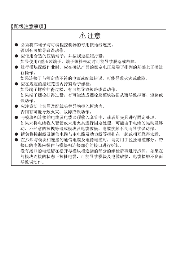
[Wiring Precautions]
WARNING
● Perform installation and wiring after disconnecting the power supply at all
phases externally.
If the power is not disconnected at all phases an electric shock, product
damage or malfunction may result.
● When powering up or operating the module after performing installation or
wiring work, always attach the terminal cover that came with the product.
It may cause an electric shock if the terminal cover is not attached.
A-2
Page 4
[Wiring Precautions]
CAUTION
● Be sure to ground the FG terminal to the class-3 or higher grounding.
Otherwise there will be a danger of malfunctions.
● Use applicable solderless terminals and tighten them with the specified
torque. If any solderless spade terminal is used, it may be disconnected when
the terminal screw comes loose, resulting in failure.
● Perform correct wiring for the module according to the product's rated voltage
and terminal arrangement. Connecting to a power supply different from rating
or mis-wiring may cause fire and/or product failure.
● Fix terminal screws securely within the specified torque range. Loose terminal
screws may cause short circuit or malfunction.
Overtightening can damage the screw and/or module, resulting in drop, short
circuit, or malfunction.
● Make sure foreign objects do not get inside the module, such as dirt and wire
chips. It may cause fire, product failure or malfunction.
● Be sure to fix the wires or cables that are connected to the module in place,
either by running them through a duct or by using clamps.
If the cables are not fixed in one of these ways, dispersion, movement, or
careless pulling of the cables may cause damage to the module or
malfunction due to cable contact faults.
● Do not install the control lines together with the communication cables, or
bring them close to each other. Failure to do so may cause malfunctions due
to noise.
● When disconnecting a communication or power supply cable from the
module, do not pull on the cable itself.
Disconnect cables fitted with connectors by holding and pulling the cable
connector. Disconnect cables not fitted with a connector by removing the
screws from the part connected to the module.
Pulling on a cable that is connected to the module can cause damage to the
module or cable, or malfunction due to cable connection faults.
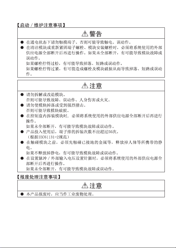
[Starting and Maintenance Precautions]
WARNING
● Do not touch the terminals when the power is on. It may cause an electric
shock or malfunction.
● Perform cleaning the module after turning off the all external power supply for
sure. If you do not switch off the external power supply, it will cause electric
shock.
A-3
Page 5
[Starting and Maintenance Precautions]
CAUTION
● Never try to disassemble or modify module. It may cause product failure,
malfunction, fire or cause injury.
● Do not drop or apply strong shock to the module case. Failure to do so may
damage the module.
● Make sure to switch all phases of the external power supply off before
installing or removing the module to/from the panel.
If you do not switch off the external power supply, it will cause failure or
malfunction of the module.
● Always set the setting pins for pulse and external input voltage after externally
shutting down all phases of the power supply.
Failure to shut down all phases of the power supply may cause a failure or
malfunction of the module.
● Do not install/remove the terminal block more than 50 times after the first use
of the product. (IEC 61131-2 compliant)
[Disposal Precautions]
CAUTION
● When disposing of the product, treat it as industrial waste.
A-4
Page 6

A-5
Page 7

A-6
Page 8
A-7
Page 9
A-8
Page 10

CONDITIONS OF USE FOR THE PRODUCT
(1) Mitsubishi programmable controller ("the PRODUCT") shall be used in
conditions;
i) where any problem, fault or failure occurring in the PRODUCT, if any,
shall not lead to any major or serious accident; and
ii) where the backup and fail-safe function are systematically or
automatically provided outside of the PRODUCT for the case of any
problem, fault or failure occurring in the PRODUCT.
(2) The PRODUCT has been designed and manufactured for the purpose of
being used in general industries.
MITSUBISHI SHALL HAVE NO RESPONSIBILITY OR LIABILITY
(INCLUDING, BUT NOT LIMITED TO ANY AND ALL RESPONSIBILITY
OR LIABILITY BASED ON CONTRACT, WARRANTY, TORT, PRODUCT
LIABILITY) FOR ANY INJURY OR DEATH TO PERSONS OR LOSS OR
DAMAGE TO PROPERTY CAUSED BY the PRODUCT THAT ARE
OPERATED OR USED IN APPLICATION NOT INTENDED OR
EXCLUDED BY INSTRUCTIONS, PRECAUTIONS, OR WARNING
CONTAINED IN MITSUBISHI'S USER, INSTRUCTION AND/OR SAFETY
MANUALS, TECHNICAL BULLETINS AND GUIDELINES FOR the
PRODUCT.
("Prohibited Application")
Prohibited Applications include, but not limited to, the use of the PRODUCT
in;
• Nuclear Power Plants and any other power plants operated by Power
companies, and/or any other cases in which the public could be
affected if any problem or fault occurs in the PRODUCT.
• Railway companies or Public service purposes, and/or any other cases
in which establishment of a special quality assurance system is
required by the Purchaser or End User.
• Aircraft or Aerospace, Medical applications, Train equipment, transport
equipment such as Elevator and Escalator, Incineration and Fuel
devices, Vehicles, Manned transportation, Equipment for Recreation
and Amusement, and Safety devices, handling of Nuclear or
Hazardous Materials or Chemicals, Mining and Drilling, and/or other
applications where there is a significant risk of injury to the public or
property.
A-9
Page 11

Notwithstanding the above, restrictions Mitsubishi may in its sole discretion,
authorize use of the PRODUCT in one or more of the Prohibited
Applications, provided that the usage of the PRODUCT is limited only for
the specific applications agreed to by Mitsubishi and provided further that
no special quality assurance or fail-safe, redundant or other safety features
which exceed the general specifications of the PRODUCTs are required.
For details, please contact the Mitsubishi representative in your region.
A-10
Page 12
REVISIONS
*The manual number is given on the bottom right of the cover.
Print date *Manual number Revision
October 1997 IB(NA)-66822-A First edition
November 1998 IB(NA)-66822-B Full revision
July 2005 IB(NA)-66822-C
September 2006 IB(NA)-66822-D
December 2011 IB(NA)-66822-E
April 2015 IB(NA)-66822-F
June 2018 IB(NA)-66822-G The standard name (standard number) for the
Partial correction
SAFETY PRECAUTIONS
Partial correction
SAFETY PRECAUTIONS
Partial correction
SAFETY PRECAUTIONS, MANUALS, Chapter 1,
2, Section 2.1, 2.2, 2.3, 2.4, Chapter 3, Section
4.1, 4.2, Chapter 5, Section 5.3, 5.4, 5.5
Addition
SAFETY PRECAUTIONS (Chinese),
CONDITIONS OF USE FOR THE PRODUCT
Partial correction
Section 2.1, 2.2, 2.3, 2.4, Chapter 3,
Section 4.1, 5.3
Chinese standardized law is added.
Japanese Manual Version IB-68910-G
This manual confers no industrial property rights or any rights of any other kind,
nor does it confer any patent licenses. Mitsubishi Electric Corporation cannot be
held responsible for any problems involving industrial property rights which may
occur as a result of using the contents noted in this manual.
© 1997 MITSUBISHI ELECTRIC CORPORATION
A-11
Page 13

CONTENTS
1. OVERVIEW .................................................................................................... 1
2. SPECIFICATION............................................................................................ 2
2.1 Performance Specifications for AJ65BT-D62........................................ 2
2.2 Performance Specifications for AJ65BT-D62D ..................................... 4
2.3 Performance Specifications for AJ65BT-D62D-S1 ............................... 6
2.4 Interface Specifications for External Device Connections..................... 8
3. PART IDENTIFICATION NOMENCLATURE AND SETTINGS.................... 12
4. LOADING AND INSTALLATION .................................................................. 17
4.1 Handling Precautions.......................................................................... 17
4.2 Installation Environment...................................................................... 18
5. WIRING ........................................................................................................ 19
5.1 Wiring Method to Each Module ........................................................... 19
5.2 Precautions When Wiring to the Pulse Generator .............................. 20
5.3 Example of Wiring for the Pulse Generator ......................................... 22
5.4 Example of Wiring Between a Control Device and External Input
Terminals (PRESET, F.START).......................................................... 25
5.5 Example of Wiring to the External Output Terminals (EQU1 to EQU2)
............................................................................................................ 26
6. EXTERNAL DIMENSIONS ........................................................................... 27
7. Information for the Chinese Standardized Low ............................................ 27
A-12
Page 14
MANUAL
User's Manual
The manuals related to this product are listed below.
Please place an order as needed.
Manual name
High-Speed Counter Module type
AJ65BT-D62/AJ65BT-D62D/AJ65BT-D62D-S1 User's Manual
Related Manuals
Manual name
CC-Link System Master/Local Module Type AJ61BT11/A1SJ61BT11
User's Manual
CC-Link System Master/Local Module Type
AJ61QBT11/A1SJ61QBT11 User's Manual
CC-Link System Master/Local Module User's Manual
MELSEC-L CC-Link System Master/Local Module Use's Manual
Manual number
(Model code)
IB-66823
(13JL45)
Manual number
(Model code)
IB-66721
(13J872)
IB-66722
(13J873)
SH-080394E
(13JR64)
SH-080895ENG
(13JZ41)
COMPLIANCE WITH EMC AND LOW VOLTAGE DIRECTIVES
(1) Method of ensuring compliance
To ensure that Mitsubishi programmable controllers maintain EMC
and Low Voltage Directives when incorporated into other
machinery or equipment, certain measures may be necessary.
Please refer to one of the following manuals.
• User's manual for the CPU module or head module used
• Safety Guidelines (this manual is included with the CPU module,
base unit, or head module)
The CE mark on the side of the programmable controller indicates
compliance with EMC and Low Voltage Directives.
(2) Additional measures
To ensure that this product maintains EMC and Low Voltage
Directives, please refer to one of the manuals listed under (1).
A-13
Page 15

1. OVERVIEW
This manual describes specifications, handling, and wiring of the
AJ65BT-D62/AJ65BT-D62D/AJ65BT-D62D-S1 high-speed counter
modules (hereafter abbreviated as high-speed counter module) to be
used in a CC-Link system.
After unpacking the product you purchased, check to see that the
following equipment is included.
Product name Quantity
High-speed counter module 1
There are three types of high-speed counter module, as indicated
below:
Item AJ65BT-D62 AJ65BT-D62D AJ65BT-D62D-S1
Type
External input
Maximum counting speed
CC-Link station type Remote device station
Signal level 24-bit binary (0 to 16777215)
Counting switching 200k/10k
Preset
Function start
DC input sink
output type
5/12/24VDC, 2 to 5mA
Maximum
200kPPS
Differential input sink
Maximum 400kPPS
Phase 1: 400k
Phase 2: 300k
output type
Differential input
/10k
5/12/24VDC
2 to 5mA
1
Page 16

2. SPECIFICATION
Specifications for the high-speed counter module are given below.
For general specifications, refer to the user's manual.
2.1 Performance Specifications for AJ65BT-D62
Item Specification
Setting switch for counting speed switching HIGH side LOW side
Number of channels 2 channels
Count input
signal
Counter
Coincidence
output
External
input
External
output
CC-Link station type Remote device station
Number of occupied stations 4 stations
Connection cable CC-Link dedicated cable
Dielectric withstand voltage
Phase 1 phase input, 2 phase input
Signal level
(A, B)
Counting
speed
(maximum)
1 phase input 200kPPS 10kPPS
*1
2 phase input 200kPPS 7kPPS
5VDC
12VDC
24VDC
2 to 5mA
Signal level 24-bit binary 0 to 16777215
Model
Smallest count pulse width
Adjust rise/fall
time of input
to 2μs or less.
Duty ratio:
50%
UP/DOWN preset counter and ring counter
2.5 s
(1, 2 phase input)
5 s
2.5 s
functions
100 s
50
50
s
s
(1 phase
input)
Comparison range 24-bit binary
Comparison result
Set value < Count value
Set value = Count value
Set value > Count value
Preset 5/12/24VDC, 2 to 5mA
Function start
Response time
OFF ON: 0.5ms or less
ON OFF: 3ms or less
Coincidence output 2A/common
Response time 0.1ms or less
1 minute at 500V AC between batch of DC
external terminals and ground
142 s
(2 phase
71
input)
s71 s
2
Page 17

Item Specification
Insulation resistance
Noise durability
Connected terminal block 27 terminal blocks (seven M3.5 screws)
Applicable wire size 0.75 to 2.00mm
Applicable crimp contact RAV1.25-3, RAV2-3.5 (JIS C 2805 compliant)
Module installation screws
Applicable DIN rail
External power supply
Allowable momentary power failure period 1ms
Weight 0.41kg
*1 Counting speed is affected by the duration of rise and fall periods. The speeds that can be
counted are indicated in the table below.
Take note that the count may become incorrect when a pulse with a large rise or fall period
is counted.
Counting speed
setting switch
Rise/fall period
t = 2µs or less 200kPPS 200kPPS 10kPPS 7kPPS
t = 25µs or less 10kPPS 10kPPS 1kPPS 700PPS
t = 500µs - - 500PPS 250PPS
HIGH LOW
1 phase
input
2 phase
10M or more on an insulation resistance tester
at 500V DC between batch of DC external
terminals and ground
Based on a noise simulator with 500Vp-p noise
voltage, 1µs noise width and 25-60Hz noise
frequency
M4×0.7mm(0.03in.)×16mm(0.63in.) or larger
screws (tightening torque range 0.78 to 1.18N•m)
Can also be mounted using a DIN rail
TH35-7.5Fe, TH35-7.5Al, TH35-15Fe
(JIS C 2812 compliant)
18 to 28.8VDC
Current consumption: 70mA (for 24VDC)
input
1 phase
input
2 phase
input
2
tt
3
Page 18

2.2 Performance Specifications for AJ65BT-D62D
(2 phase
input)
(1 phase
input)
s
71
142 s
100 s
s
71
s50 s
50
Item Specification
Setting switch for counting speed switching HIGH side LOW side
Number of channels 2 channels
Phase 1 phase input, 2 phase input
Count input
signal
Signal level
(A, B)
Counting
speed
(maximum)
1 phase input 400kPPS 10kPPS
*1
2 phase input 300kPPS 7kPPS
Signal level 24-bit binary 0 to 16777215
Model
Counter
Smallest count pulse width
Adjust rise/fall
time of input
to 2μs or less.
Duty ratio:
50%
Comparison range 24-bit binary
Coincidence
output
Comparison result
Preset 5/12/24VDC, 2 to 5mA
External input
Function start
Response time
External
output
Coincidence output 2A/common
Response time 0.1ms or less
CC-Link station type Remote device station
Number of occupied stations 4 stations
Connection cable CC-Link dedicated cable
Dielectric withstand voltage
Insulation resistance
EIA Standard RS-422-A
Differential line driver level
(AM26LS31 (manufactured by Texas Instrument
Japan) or equivalent)
UP/DOWN preset counter and ring counter
2.5 s
1.25
1.25
s
(1 phase
input)
1 minute at 500V AC between batch of DC
external terminals and ground
10M or more across all DC external terminals
and grounding terminal using a 500VDC
insulation resistance tester
functions
3.3 s
1.65
1.65
s s
s
(2 phase
input)
Set value < Count value
Set value = Count value
Set value > Count value
OFF ON: 0.5ms or less
ON OFF: 3ms or less
4
Page 19

Item Specification
Noise durability
Connected terminal block 27 terminal blocks (seven M3.5 screws)
Applicable wire size 0.75 to 2.00mm
Applicable crimp contact RAV1.25-3, RAV2-3.5 (JIS C 2805 compliant)
Module installation screws
Applicable DIN rail
External power supply
Allowable momentary power failure period 1ms
Weight 0.42kg
*1 Counting speed is affected by the duration of rise and fall periods. The speeds that can be
counted are indicated in the table below.
Take note that the count may become incorrect when a pulse with a large rise or fall period
is counted.
Counting speed
setting switch
Rise/fall period
t = 0.1µs or less 400kPPS 300kPPS - -
t = 1.25µs or less 200kPPS 200kPPS 10kPPS 7kPPS
t = 12.5µs or less 20kPPS 20kPPS 1kPPS 700PPS
t = 250µs or less - - 500PPS 250PPS
HIGH LOW
1 phase
input
2 phase
Based on a noise simulator with 500Vp-p noise
voltage, 1µs noise width and 25-60Hz noise
frequency
M4×0.7mm(0.03in.)×16mm(0.63in.) or larger
screws (tightening torque range 0.78 to
1.18N•m)
Can also be mounted using a DIN rail
TH35-7.5Fe, TH35-7.5Al, TH35-15Fe
(JIS C 2812 compliant)
18 to 28.8VDC
2 phase
input
input
Current consumption: 100mA (for 24VDC)
1 phase
input
2
tt
5
Page 20

2.3 Performance Specifications for AJ65BT-D62D-S1
(2 phase
input)
(1 phase
input)
142 s
7171
100 s
5050
s s s s
Item Specification
Setting switch for counting speed switching HIGH side LOW side
Number of channels 2 channels
Phase 1 phase input, 2 phase input
Count input
signal
Signal level
(A, B)
Counting
speed
(maximum)
1 phase input 400kPPS 10kPPS
*1
2 phase input 300kPPS 7kPPS
Signal level 24-bit binary 0 to 16777215
Model
Counter
Smallest count pulse width
Adjust rise/fall
time of input
to 2μs or less.
Duty ratio:
50%
Comparison range 24-bit binary
Coincidence
output
Comparison result
Preset
External input
Function start 5/12/24VDC, 2 to 5mA
Response time
External
output
Coincidence output 2A/common
Response time 0.1ms or less
CC-Link station type Remote device station
Number of occupied stations 4 stations
Connection cable CC-Link dedicated cable
Dielectric withstand voltage
EIA Standard RS-422-A
Differential line driver level
(AM26LS31 (manufactured by Texas Instrument
Japan) or equivalent)
UP/DOWN preset counter and ring counter
2.5 s
1.25
1.25
s
s
(1 phase
input)
EIA Standard RS-422-A differential type line
{equivalent to AM26LS31 (Japan Texas
1 minute at 500V AC between batch of DC
external terminals and ground
functions
3.3 s
1.65
1.65
s
s
(2 phase
input)
Set value < Count value
Set value = Count value
Set value > Count value
driver level
Instruments make)}
OFF ON: 0.5ms or less
ON OFF: 3ms or less
6
Page 21

Item Specification
tt
Insulation resistance
Noise durability
Connected terminal block 27 terminal blocks (seven M3.5 screws)
Applicable wire size 0.75 to 2.00mm
Applicable crimp contact RAV1.25-3, RAV2-3.5 (JIS C 2805 compliant)
Module installation screws
Applicable DIN rail
External power supply
Allowable momentary power failure period 1ms
Weight 0.42kg
*1 Counting speed is affected by the duration of rise and fall periods. The speeds that can be
counted are indicated in the table below.
Take note that the count may become incorrect when a pulse with a large rise or fall period
is counted.
Counting speed
setting switch
Rise/fall period
t = 0.1µs or less 400kPPS 300kPPS - -
t = 1.25µs or less 200kPPS 200kPPS 10kPPS 7kPPS
t = 12.5µs or less 20kPPS 20kPPS 1kPPS 700PPS
t = 250µs or less - - 500PPS 250PPS
HIGH LOW
1 phase
input
2 phase
10M or more across all DC external terminals
and grounding terminal using a 500VDC
insulation resistance tester
Based on a noise simulator with 500Vp-p noise
voltage, 1µs noise width and 25-60Hz noise
frequency
M4×0.7mm(0.03in.)×16mm(0.63in.) or larger
screws (tightening torque range 0.78 to
1.18N•m)
Can also be mounted using a DIN rail
TH35-7.5Fe, TH35-7.5Al, TH35-15Fe
(JIS C 2812 compliant)
18 to 28.8VDC
2 phase
input
input
Current consumption: 120mA (for 24 VDC)
1 phase
input
2
7
Page 22

2.4 Interface Specifications for External Device
1/3W
1/3W
1/3W
Pulse input
voltage setting pin
For 5V
For 12V
For 24V
510
4.7k
4.7k
1/3W
1/3W
1/3W
Pulse input
voltage setting pin
For 5V
For 12V
For 24V
510
4.7k
4.7k
Connections
The table below indicates the external device interfaces for the AJ65BTD62, AJ65BT-D62D and AJ65BT-D62D-S1 high-speed counter
modules.
(1) External device interfaces for AJ65BT-D62
I/O
classify
-cation
Input
4.7k
4.7k
4.7k
4.7k
Internal Circuit
510
510
1/3W
1/3W
1/3W
External input
voltage setting pin
1/3W
1/3W
1/3W
External
input
voltage
setting pin
Terminal
number*1Signal Name Operation
Phase A pulse
input 24V
Phase A pulse
8
input 12V
(15)
Phase A pulse
9
Phase A pulse
(16)
input COM
Phase B pulse
input 24V
Phase B pulse
10
input 12V
(17)
Phase B pulse
11
Phase B pulse
(18)
input COM
Preset input
Preset input
12
For 5V
(19)
For 12V
For 24V
For 5V
For 12V
For 24V
Preset input
13
(20)
Function start
input 24V
Function start
14
input 12V
(21)
Function start
--
input 5V
input 5V
24V
12V
5V
COM
input 5V
8
Operating
Input
(guaranteed
value)
When ON 21.6 to 26.4V 2 to 5mA
When OFF 5V or less 0.1mA or less
When ON 10.8 to 13.2V 2 to 5mA
When OFF 4V or less 0.1mA or less
When ON 4.5 to 5.5V 2 to 5mA
When OFF 2V or less 0.1mA or less
When ON 21.6 to 26.4V 2 to 5mA
When OFF 5V or less 0.1mA or less
When ON 10.8 to 13.2V 2 to 5mA
When OFF 4V or less 0.1mA or less
When ON 4.5 to 5.5V 2 to 5mA
When OFF 2V or less 0.1mA or less
When ON 21.6 to 26.4V 2 to 5mA
When OFF 5V or less 0.1mA or less
When ON 10.8 to 13.2V 2 to 5mA
When OFF 4V or less 0.1mA or less
When ON 4.5 to 5.5V 2 to 5mA
When OFF 2V or less 0.1mA or less
Response
When ON 21.6 to 26.4V 2 to 5mA
When OFF 5V or less 0.1mA or less
When ON 10.8 to 13.2V 2 to 5mA
When OFF 4V or less 0.1mA or less
When ON 4.5 to 5.5V 2 to 5mA
When OFF 2V or less 0.1mA or less
Response
time
time
OFFON
0.5ms or less
OFFON
0.5ms or less
-
-
current
(guaranteed
value)
ONOFF
3ms or less
ONOFF
3m
s or less
Page 23

I/O
classify
-cation
Output
Internal Circuit
Terminal
number*1Signal Name Operation
22
(24)
23
(25)
26 12/24V
27 0V
Operating voltage :10.2 to 30V
EQU1
Rated current :0.5 A/point
Maximum inrush current: 4A 10 ms
Maximum voltage drop at ON: 1.5V
EQU2
Response time: OFFON 0.1 ms o r less
ONOFF 0.1 ms or less
Input voltage: 10.2 to 30V
Current consumption: 8mA (TYP 24VDC)
*1 Figure inside ( ) indicates the terminal number of channel 2.
Input
(guaranteed
value)
Operating
current
(guaranteed
value)
9
Page 24

(2) External device interfaces for AJ65BT-D62D
I/O
classify
-cation
Input
Output
Internal Circuit
5V
5V
510
4.7k
4.7k
510
4.7k
4.7k
1/3W
1/3W
1/3W
External input
voltage setting pin
1/3W
1/3W
1/3W
External
input
voltage
setting pin
For 5V
For 12V
For 24V
For 5V
For 12V
For 24V
Terminal
number*1Signal Name Operation
8
Phase A
(15)
pulse input
9
(16)
pulse input
10
(17)
pulse input
11
(18)
pulse input
Preset input
Preset input
12
(19)
Preset input
13
(20)
14
(21)
start input 5V
--
22
(24)
23
(25)
26 12/24V
27 0V
EIA Standard RS-422-A line receiver
(AM26C32 (manufactured by Texas
Instruments Japan Limited.) or equivalent)
Phase A
The specifications of line receiver are as
follows:
• VIT+ differential input ON voltage (H level
threshold voltage): 0.1V
• VIT- differential input OF F voltage (L level
Phase B
Phase B
Function
start input
Function
start input
Function
threshold voltage): -0.1V
• Vhys hysteresis voltage (VIT+ - VIT-):
60mV (A current type line driver cannot be
used.)
When ON 21.6 to 26.4V 2 to 5mA
24V
When OFF 5V or less 0.1m A or less
When ON 10.8 to 13.2V 2 to 5mA
12V
When OFF 4V or less 0.1m A or less
When ON 4.5 to 5.5V 2 to 5mA
5V
When OFF 2V or less 0.1m A or less
Response
COM
When ON 21.6 to 26.4V 2 to 5mA
When OFF 5V or less 0.1m A or less
24V
When ON 10.8 to 13.2V 2 to 5mA
When OFF 4V or less 0.1m A or less
12V
When ON 4.5 to 5.5V 2 to 5mA
When OFF 2V or less 0.1m A or less
Response
Operating voltage: 10.2 to 30V
EQU1
Rated current: 0.5A/point
Max. inrush current: 4A 10ms
Max. voltage drop at ON: 1.5V
EQU2
Response time: OFFON 0.1ms or less
ONOFF 0.1ms or less
Input voltage: 10.2 to 30V
Current consumption: 8mA (TYP 24VDC)
*1 Figure inside ( ) indicates the terminal number of channel 2.
time
time
Input
(guaranteed
value)
OFFON
0.5ms or less
OFFON
0.5ms or less
Operating
current
(guaranteed
value)
ONOFF
3ms or less
ONOFF
3ms or less
10
Page 25

(3) External device interfaces for AJ65BT-D62D-S1
I/O
classify
-cation
Internal Circuit
5V
5V
Input
Output
510Ω
4.7kΩ
4.7kΩ
5V
1/3W
1/3W
1/3W
External input
voltage setting pin
*1 Figure inside ( ) indicates the terminal number of channel 2.
For 5V
For 12V
For 24V
Terminal
number
*1
8
(16)
9
(17)
10
(18)
11
(19)
12
(20)
13
(21)
14
(22)
15
(23)
24
(25)
26 12/24V
27 0V
Signal
Operation
Name
Phase A
pulse input
Phase A
pulse input
EIA Standard RS-422-A line receiver
(AM26C32 (manufactured by Texas
Instruments Japan Limited.) or equivalent)
The specifications of line receiver are as
Phase B
follows:
pulse input
• VIT+ differential input ON voltage (H level
threshold voltage): 0.1V
• VIT- differential input O FF voltage (L level
Phase B
pulse input
Function
start input
Function
start input
Function
start input
threshold voltage): -0.1V
• Vhys hysteresis voltage (VIT+ - VIT-):
60mV (A current type line driver cannot be
used.)
Preset
input
Preset
input
When ON 21.6 to 26.4V 2 to 5mA
When OFF 5V or less 0.1mA or less
24V
When ON 10.8 to 13.2V 2 to 5mA
When OFF 4V or less 0.1mA or less
12V
When ON 4.5 to 5.5V 2 to 5mA
When OFF 2V or less 0.1mA or less
5V
Response
COM
time
Operating voltage: 10.2 to 30V
Rated current: 0.5 A/point
Maximum inrush current: 4A 10 ms
EQU1
Maximum voltage drop at ON: 1.5V
Response time: OFFON 0.1 ms or less
ONOFF 0.1 ms or less
Input voltage: 10.2 to 30V
Current consumption: 8mA (TYP 24VDC)
Input
(guaranteed
value)
OFFON
0.5ms or less
Operating
current
(guaranteed
value)
ONOFF
3ms or less
11
Page 26

3. PART IDENTIFICATION NOMENCLATURE AND
10
1
SETTINGS
This section shows the name of each part within the high-speed counter
module and explains how to set each switch. (The illustration below
indicates the AJ65BT-D62).
7) 6) 2) 1)
8) 3)4)
No. Name Description
Station number setting
1)
switch
Transmission baud
2)
rate setting switch
Used to set the transmission speed of the high-speed counter
module. (For data link)
Used to set the station number of the high-speed
counter module between 1 and 61.
(When shipped from the factory: 00)
Setting number Transmission baud rate
0 156kbps (factory set value)
1 625kbps
2 2.5Mbps
3 5Mbps
4 10Mbps
Other than 0 to 4
Not used
(When a number other than 0 to 4 is
used, the L ERR. LED lights up and
a communication error is
generated.)
9)
5)
12
Page 27

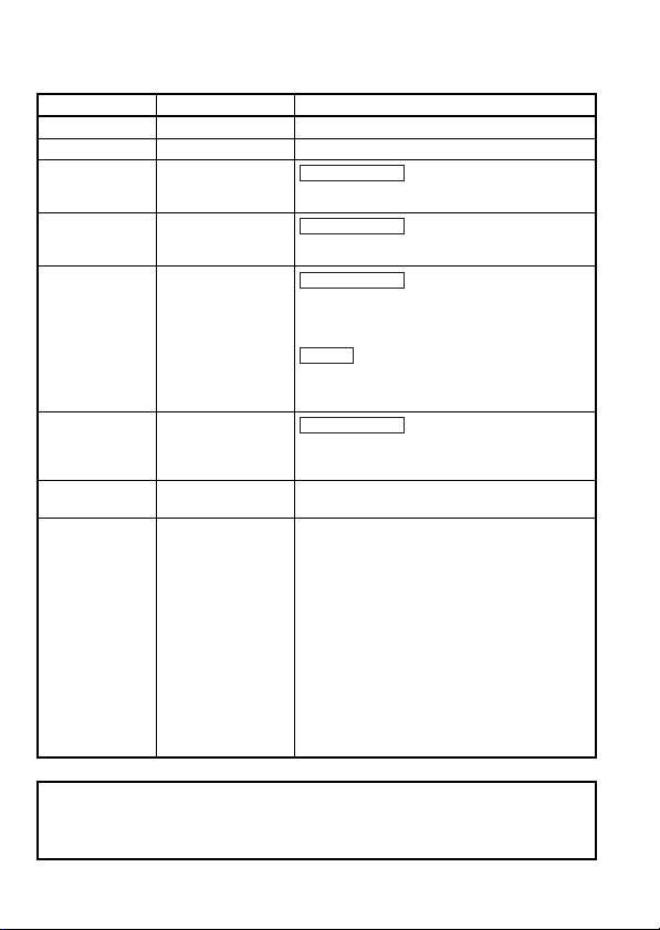
No. Name Description
Counting speed setting
3)
switch
Ring counter setting
4)
switch
5) Reset switch
6) LED display
LOW side: With Phase 1 input, up to 10kPPS and with Phase
HIGH side: With Phase 1 input, up to 400(200)kPPS and with
Set whether the ring counter function can be used.
• When ring counter used: ON side
• When ring counter not used: OFF side
Hardware reset
Initializes the remote register for the high-speed counter
module.
By turning the switch on, the initial data processing request flag
turns on.
Lit: power is on
PW
Unlit: power is off
Lit: operating normally
RUN
Unlit: 24V DC power supply is disconnected or WDT error
Lit: communication is normal
L RUN
Unlit: communication is disconnected (time over error)
SD SD: lit when data is being transmitted
RD RD: lit when data is being transmitted
On: Communication data error (CRC error)
Flashing at constant interval: Station number settings and
L ERR.
Flashing at non-constant
interval:
Off: Normal communication
2, up to 7kPPS can be counted.
Phase 2, up to 300(200)kPPS can be counted.
The figures in ( ) are for the AJ65BT-D62.
(When shipped from the factory: set at HIGH side)
(When shipped from the factory: set at OFF side)
baud rate settings are changed
during power supply.
Termination resistor is not
provided or the unit or the
dedicated cable for CC-Link is
subject to noise.
13
Page 28

No. Name Description
Lights up when voltage is being applied to the Phase A pulse
A
input terminal.
Lights up when voltage is being applied to the Phase B pulse
B
input terminal.
DEC Lights up during subtraction.
Lights up stays lit when voltage is being applied to the PRESET
terminal.
7) LED display
8) Terminal block
PRE
Turns off when the external preset detection reset command
rises.
Lights up when voltage is being applied to the F.START
F ST.
terminal.
Lights up when coincidence output set value No.1 = counter
EQU1
value.
Lights up when coincidence output set value No.2 = counter
EQU2
value. (This does not exist in the AJ65BT-D62D-S1 model.)
• For AJ65BT-D62
Pin
Number
Signal name
1DA15
2DB16
3SG17
4 SLD 18
5 24V 19 PRESET
6F.G.20 COM
7 24G 21 F.START
8
923EQU2
10
11 25 EQU2
CH1
12 PRESET 26 12/24V
13 COM 27 COM
14 F.START
Number
A
B
Pin
Signal name
A
B
CH2
22
24
CH1
CH2
EQU1
EQU1
14
Page 29

No. Name Description
• For AJ65BT-D62D
8) Terminal bl ock
Pin
Number
• For AJ65BT-D62D-S1
Pin
Number
Signal name
1DA15
2DB16 A
3SG17BB
4SLD18 B
5 24V 19 PRESET
6F.G.20 COM
7 24G 21 F.START
8
9A
10
11 B
12 PRESET 26 12/24V
13 COM 27 COM
14 F.START
1DA16
2DB17 A
3SG18BB
4SLD19 B
5 24V 20 PRESET
6 F.G. 21 PRESET
7 24G 22
8
9A
10
11 B
12 PRESET 27 COM
13 PRESET
14
15
CH1
Signal name
CH1
A
B
A
B
F.START
Number
A22
B24
Number
A23
B 25 CH2 EQU1
Pin
Pin
Signal name
A
CH2
EQU1
CH1
23 EQU2
25 EQU2
24 CH1 EQU1
26 12/24V
CH2
Signal name
CH2
EQU1
A
F.START
A
A
15
Page 30

No. Name Description
(When a jumper is connected to 24V)
(When a jumper is connected to 12V)
(When a jumper is connected to 5V)
Circuit board
Jumper
AJ65BT-D62
AJ65BT-D62D
AJ65BT-D62D-S1
This is the same for CH2.
Pulse/external input
9)
voltage setting pin
16
Page 31

4. LOADING AND INSTALLATION
4.1 Handling Precautions
(1) Do not drop or apply strong shock to the module case.
(2) Do not remove the module printed circuit board from the case.
This will cause a breakdown.
(3) Be careful not to let foreign matters such as fillings or wire chips
get inside the module. If these do get inside, remove them.
(4) Tighten the module installation screws within the following
tightening torque range.
Screw Tightening Torque Range
Module installation screws
(M4 screw)
Terminal block terminal screws
(M3.5 screw)
Module installation screws
(M4 screw)
(5) When using a DIN rail adapter, take note of the following points
when mounting the DIN rail.
(a) Applicable DIN rail type (JIS C 2812 compliant)
TH-35-7.5Fe
TH-35-7.5Al
TH-35-15Fe
(b) Screw spacing when mounting the DIN rail
When mounting the DIN rail, tighten the screws at a pitch of
200mm (7.84in.) or less.
0.78 to 1.18N•m
0.59 to 0.88N•m
0.78 to 1.18N•m
17
Page 32

4.2 Installation Environment
Do not install the A series programmable controller in the following
environment.
(1) Where the ambient temperature exceeds the 0 to 55°C range.
(2) Where the ambient humidity exceeds the 10 to 90% RH range.
(3) Where condensation is produced by sudden temperature changes.
(4) Where corrosive or combustible gas is present.
(5) Where dust, iron powder and other conductive powder, oil mist,
salt, or organic solvents are prevalent.
(6) In direct sunlight.
(7) Where a strong electric or magnetic field is generated.
(8) Where vibration and shock may be transmitted directly to the
module.
18
Page 33

5. WIRING
DA
DB
DG
SLD
FG
DA
DB
DG
SLD
FG
DA
DB
DG
SLD
FG
Master module
Terminal
resistor
Terminal
resistor
Remote moduleHigh-speed counter module
(Blue) (Blue) (Blue) (Blue)
CC-Link
dedicated cable
CC-Link
dedicated cable
(Yellow)
(White)
(Yellow)
(White)
(Yellow)
(White)
(Yellow)
(White)
This section explains the wiring for the high-speed counter module.
5.1 Wiring Method to Each Module
The following diagram shows the wiring of the master module, remote
module and high-speed counter module with dedicated cable for CCLink.
Point
Always connect the "terminal resistors" provided with the master module
to the modules at both ends of data link.
(Connect between DA and DB)
19
Page 34

5.2 Precautions When Wiring to the Pulse Generator
(1) Implement the following types of noise measures for high-speed
pulse input.
(a) Always use a twisted shielded wire and perform class 3
grounding.
(b) Do not run the twisted wire parallel to the power cord or I/O line
with a lot of noise. Secure a distance of 150mm (5.91in.) or
more and run the cable for the shortest distance possible.
(2) In the case of Phase 1 input, always wire to the Phase A side.
(3) The high-speed counter module counts up when a pulse-state
noise is input, resulting in a count error.
(4) Wiring for noise measure is indicated below.
Highspeed
counter
module
Inverter
Terminal
block
Terminal
block
*1
For a strong power device
such as an inverter, leave a
distance of 150mm (5.91in.)
or more from the I/O line
(Also be careful of the
wiring inside the panel.)
EWV
Joint box
*2
AC motor
Carrier
Encoder
*1 When using metal piping, avoid intermingling solenoid valves and inductive loads in the
same piping. Also, if an isolation distance from a strong power line such as duct wiring
cannot be secured, use a CVVS or other shielded cable for the strong power line.
20
Page 35

*2 Make the distance from the encoder to the joint box short. When there is long distance from
the high-speed counter module to the encoder, voltage drops will occur. Therefore, use a
measuring device such as a tester on the joint box terminal block to check whether the
voltage while the encoder is operating and at a standstill is within the rated voltage for the
encoder. If the drop in voltage is large, make the cable size thicker or use a 24V DC type
encoder with small current consumption.
• Grounding for the twisted, shielded cable is done on the encoder side (in the joint
box). (The following is an example of a connection for a 24V sink load.)
+24V
Current for the encoder
To A
To B
To the high-speed
counter module
The shielded cable for the encoder and that for the twisted cable
are connected inside the joint box. If the shielded cable for the
encoder is not grounded inside the encoder, then perform
grounding inside the joint box as shown by the dotted line.
0V
24V
E
A
B
To the encoder
E
21
Page 36

5.3 Example of Wiring for the Pulse Generator
(1) Example of wiring to an open collector output type pulse generator
(24V DC)
AJ65BT-D62
510
4.7k
4.7k
510
4.7k
4.7k
*Set the pulse input voltage setting pin to the side.
Pulse input
1/3W
voltage setting pin*
1/3W
1/3W
A
Shielded twisted
pair cable
A
Pulse input
1/3W
voltage setting pin*
1/3W
1/3W
24VDC
External
power supply
0V
B
B
Shielded twisted
pair cable
Point
The wiring between the AJ65BT-D62 and the encoder should be separate
from the power supply line and signal line.
• An example is shown below.
AJ65BT-D62
A
A
External
+
power
-
supply
• An example of wiring to be avoided.
AJ65BT-D62
A
A
External
+
power
-
supply
Shield
Shield
Pulse generator
OUT
24V
E
OUT
24V
E
24V
0V
OUT
24V
Encoder
0V
E
OUT
24V
Encoder
0V
E
22
Page 37

(2) Example of wiring to a voltage output type pulse generator (5V DC)
AJ65BT-D62
510
4.7k
4.7k
510
4.7k
4.7k
*Set the pulse input voltage setting pin to the side.
1/3W
1/3W
1/3W
1/3W
1/3W
1/3W
External
power
supply
Pulse input
voltage
setting pin*
Pulse input
voltage
setting pin*
5VDC
0V
A
A
B
B
Shielded twisted
Shielded twisted
(3) Example of wiring to the pulse generator for a line driver
(AM26LS31 or equivalent)
AJ65BT-D62D
Shielded twisted pair cable
A
A
Shielded twisted pair cable
B
B
pair cable
pair cable
Pulse generator
OUT
GND
E
OUT
GND
E
5VDC
0V
Pulse generator
A
A
E
B
B
E
External
VCC
power
GND GND
supply
23
VCC
Page 38

AJ65BT-D62D-S1
14050
14050
A
A
B
B
PRESET
PRESET
Shielded twisted
pair cable
Shielded twisted
pair cable
Shielded twisted
pair cable
Pulse generator
A
A
E
B
B
E
Z
Z
E
External
power
supply
VCC
GND
VCC
GND
24
Page 39

5.4 Example of Wiring Between a Control Device and External Input Terminals (PRESET, F.START)
(1) When the control device (sink load type) is 12V
AJ65BT-D62, AJ65BT-D62D, AJ65BT-D62D-S1
510
4.7k
4.7k
Internal circuit is set to PRESET.
AJ65BT-D62D-S1 has F.START only.
*Set the external input voltage setting pin to the side.
(2) When the control device (source load type) is 5V
AJ65BT-D62, AJ65BT-D62D, AJ65BT-D62D-S1
510Ω
4.7kΩ
4.7kΩ
• Internal circuit is set to PRESET.
• AJ65BT-D62D-S1 has F.START only.
* Set the external input voltage setting pin to the side.
CAUTION
External
input voltage
1/3W
setting pin*
1/3W
1/3W
PRESET or F.START
Shielded twisted
pair cable
COM
External
1/3W
1/3W
1/3W
input
voltage
setting pin*
PRESET or F.START
Shielded twisted
pair cable
Controller
COM
• Set the pulse/external input voltage setting pin correctly after confirming the
rated voltage for the external power supply.
If there is a fault in the wiring (setting mistake), fire or breakdown can be
caused.
• Always set the pulse/external input voltage setting pin after shutting down all
phases of the power supply externally.
If all phases are not shut down, this will cause a breakdown of the module or
an error in operation.
• Make sure the insertion direction of the jumper for the pulse/ external-input
voltage setting pin is correct.
Incorrect insertion direction may cause the module to breakdown.
Controller
12VDC
E
5VDC
E
Jumper
Jumper
<Incorrect><Correct>
25
Page 40

5.5 Example of Wiring to the External Output Terminals (EQU1 to EQU2)
When using an EQU terminal, an external power supply in the range of
10.2V DC to 30V DC is needed to operate the internal photocoupler.
Run the wires as shown below.
(1) AJ65BT-D62, AJ65BT-D62D
AJ65BT-D62, AJ65BT-D62D
EQU1
Load
(2) AJ65BT-D62D-S1
AJ65BT-D62D-S1
Point
Even when not using an EQU terminal, wire the 12/24V terminal (pin
number: 26) and the COM terminal (pin number: 27) to an external power
supply.
If they are not wired, SW0088 to SW008B (fuse blown status) of the
master module would be on.
EQU2
12/24V
COM
EQU1
12/24V
COM
26
Load
10.2V to 30V
Load
10.2V to 30V
Page 41

6. EXTERNAL DIMENSIONS
9.5
(0.37)
63 (2.48)
2- 4.5 mounting hole
56 (2.2)
65 (2.56)
142.9 (5.63)
151.9 (5.98)
(Unit: mm (in.))
7. Information for the Chinese Standardized Low
27
Page 42

Memo29Memo
28
Page 43

Page 44

WARRANTY
Mitsubishi will not be held liable for damage caused by factors found not to be the cause of
Mitsubishi; machine damage or lost profits caused by faults in the Mitsubishi products; damage,
secondary damage, accident compensation caused by special factors unpredictable by
Mitsubishi; damages to products other than Mitsubishi products; and to other duties.
Country/
Sales office/
Region
Tel
USA MITSUBISHI ELECTRIC AUTOMATION, INC.
500 Corporate Woods Parkway, Vernon Hills, IL
60061, U.S.A.
Tel : +1-847-478-2100
Mexico MITSUBISHI ELECTRIC AUTOMATION, INC.
Mexico Branch
Mariano Escobedo #69, Col. Zona Industrial,
Tlalnepantla Edo. Mexico, C.P.54030
Tel : +52-55-3067-7500
Brazil MITSUBISHI ELECTRIC DO BRASIL COMÉRCIO
E SERVIÇOS LTDA.
Avenida Adelino Cardana, 293, 21 andar,
Bethaville, Barueri SP, Brazil
Tel : +55-11-4689-3000
Germany MITSUBISHI ELECTRIC EUROPE B.V. German
Branch
Mitsubishi-Electric-Platz 1, 40882 Ratingen,
Germany
Tel : +49-2102-486-0
UK MITSUBISHI ELECTRIC EUROPE B.V. UK Branch
Travellers Lane, Hatfield, Hertfordshire, AL10 8XB,
U.K.
Tel : +44-1707-28-8780
Ireland MITSUBISHI ELECTRIC EUROPE B.V. Irish
Branch
Westgate Business Park, Ballymount, Dublin 24,
Ireland
Tel : +353-1-4198800
Italy MITSUBISHI ELECTRIC EUROPE B.V. Italian
Branch
Centro Direzionale Colleoni-Palazzo Sirio Viale
Colleoni 7, 20864 Agrate Brianza(Milano) Italy
Tel : +39-039-60531
Spain MITSUBISHI ELECTRIC EUROPE, B.V. Spanish
Branch
Carretera de Rubí, 76-80-Apdo. 420, 08190 Sant
Cugat del Vallés (Barcelona), Spain
Tel : +34-935-65-3131
France MITSUBISHI ELECTRIC EUROPE B.V. French
Branch
25, Boulevard des Bouvets, 92741 Nanterre Cedex,
France
Tel : +33-1-55-68-55-68
Czech
MITSUBISHI ELECTRIC EUROPE B.V. Czech
Republic
Branch
Avenir Business Park, Radlicka 751/113e, 158 00
Praha5, Czech Republic
Tel : +420-251-551-470
Poland MITSUBISHI ELECTRIC EUROPE B.V. Polish
Branch
ul. Krakowska 50, 32-083 Balice, Poland
Tel : +48-12-347-65-00
MITSUBISHI ELECTRIC EUROPE B.V.
Sweden
(Scandinavia)
Fjelievägen 8, SE-22736 Lund, Sweden
Tel : +46-8-625-10-00
Russia MITSUBISHI ELECTRIC (RUSSIA) LLC St.
Petersburg Branch
Piskarevsky pr. 2, bld 2, lit “Sch”, BC “Benua”, office
720; 195027 St. Petersburg, Russia
Tel : +7-812-633-3497
HEAD OFFICE : TOKYO BUILDING, 2-7-3 MARUNOUCHI, CHIYODA-KU, TOKYO 100-8310, JAPAN
NAGOYA WORKS : 1-14, YADA-MINAMI 5-CHOME, HIGASHI-KU, NAGOYA, JAPAN
When exported from Japan, this manual does not require application to the Ministry of Economy,
Trade and Industry for service transaction permission.
Sales office/
Country/
Tel
Region
MITSUBISHI ELECTRIC TURKEY A.Ş Ümraniye
Turkey
Branch
Serifali Mahallesi Nutuk Sokak No:5, TR-34775
Umraniye/Istanbul, Turkey
Tel : +90-216-526-3990
MITSUBISHI ELECTRIC EUROPE B.V. Dubai
UAE
Branch
Dubai Silicon Oasis, P.O.BOX 341241, Dubai,
U.A.E.
Tel : +971-4-3724716
ADROIT TECHNOLOGIES
South
20 Waterford Office Park, 189 Witkoppen Road,
Africa
Fourways, South Africa
Tel : +27-11-658-8100
MITSUBISHI ELECTRIC AUTOMATION (CHINA)
China
LTD.
No.1386 Hongqiao Road, Mitsubishi Electric
Automation Center, Shanghai, China
Tel : +86-21-2322-3030
SETSUYO ENTERPRISE CO., LTD.
Taiwan
6F, No.105, Wugong 3rd Road, Wugu District, New
Taipei City 24889, Taiwan
Tel : +886-2-2299-2499
MITSUBISHI ELECTRIC AUTOMATION KOREA
Korea
CO., LTD.
7F-9F, Gangseo Hangang Xi-tower A, 401,
Yangcheon-ro, Gangseo-Gu, Seoul 07528, Korea
Tel : +82-2-3660-9530
Singapore
MITSUBISHI ELECTRIC ASIA PTE. LTD.
307, Alexandra Road, Mitsubishi Electric Building,
Singapore 159943
Tel : +65-6473-2308
Thailand
MITSUBISHI ELECTRIC FACTORY AUTOMATION
(THAILAND) CO., LTD.
12th Floor, SV.City Building, Office Tower 1, No.
896/19 and 20 Rama 3 Road,
Kwaeng Bangpongpang, Khet Yannawa, Bangkok
10120, Thailand
Tel : +66-2682-6522
Vietnam
MITSUBISHI ELECTRIC VIETNAM COMPANY
LIMITED Hanoi Branch
6th Floor, Detech Tower, 8 Ton That Thuyet Street,
My Dinh 2 Ward, Nam Tu Liem District, Hanoi,
Vietnam
Tel : +84-4-3937-8075
Indonesia
PT. MITSUBISHI ELECTRIC INDONESIA
Gedung Jaya 11th Floor, JL. MH. Thamrin No.12,
Jakarta Pusat 10340, Indonesia
Tel : +62-21-3192-6461
India
MITSUBISHI ELECTRIC INDIA PVT. LTD. Pune
Branch
Emerald House, EL-3, J Block, M.I.D.C., Bhosari,
Pune-411026, Maharashtra, India
Tel : +91-20-2710-2000
Australia MITSUBISHI ELECTRIC AUSTRALIA PTY. LTD.
348 Victoria Road, P.O. Box 11, Rydalmere, N.S.W
2116, Australia
Tel : +61-2-9684-7777
Specifications subject to change without notice.
 Loading...