

Page 1
AJ65BT-68TD Thermocouple Temperature Input Module
User,s Manual
Mitsubishi Programmable Controller
Page 2

Page 3
SAFETY PRECAUTIONS
(Read these precautions before using.)
When using Mitsubishi equipment, thoroughly read this manual and the associated manuals introduced
in this manual. Also pay careful attention to safety and handle the module properly.
These precautions apply only to Mitsubishi equipment. Refer to the CPU module user's manual for a
description of the PLC system safety precautions.
These SAFETY PRECAUTIONS classify the safety precautions into two categories: "DANGER" and
"CAUTION".
DANGER
Procedures which may lead to a dangerous condition and cause death or
serious injury if not carried out properly.
CAUTION
Procedures which may lead to a dangerous condition and cause superficial
to medium injury, or physical damage only, if not carried out properly.
Depending on circumstances, procedures indicated by
CAUTION may also be linked to serious
results.
In any case, it is important to follow the directions for usage.
Store this manual in a safe place so that you can take it out and read it whenever necessary. Always
forward it to the end user.
[DESIGN PRECAUTIONS]
DANGER
When there are communication errors with the data link, the data of the master module will be held.
Built an interlock circuit into the sequence program that will make sure the system operate safely by using
the communication status information.
CAUTION
Do not bunch the control wires or communication cables with the main circuit or power wires, or them close
to each other.
They should be installed 100 mm (3.9 in.) or more from each other.
Not doing so could result in noise that would cause malfunction.
Page 4

[INSTALLATION PRECAUTIONS]
CAUTION
The module should be used under the environmental conditions listed under the general specifications in
the manual.
Using it under any other environmental conditions could cause problems such as fire, malfunction and
damage to or deterioration of the product.
The module should be fixed securely with a DIN rail or installation screws, and then make sure to tighten it
within the range of the specified torque of the installation screws.
If the screws are loose, it may result in fallout or malfunction.
Tightening the screws too far may cause damages to the screws and/or the module, resulting in fallout or
malfunction.
Do not directly touch the module's conductive parts.
Doing so could cause malfunction or trouble in the module.
[WIRING PRECAUTIONS]
CAUTION
Before beginning any installation or wiring work, make sure all phases of the power supply have been
obstructed from the outside.
Failure to completely shut off the power supply phases may cause damages to the module or malfunction.
When turning on the power or operating the module after installation or wiring work, be sure the
module’sterminal covers are correctly attached.
Failure to attach the terminal covers may result in short circuit or failure.
The FG terminals should always be grounded using the class-3 or higher grounding designed specially for
the PLC.
Failure to ground these terminals may cause malfunction.
Use applicable solderless terminals and tighten them with the specified torque. If any solderless spade
terminal is used, it may be disconnected when the terminal screw comes loose, resulting in failure.
When wiring the module, check the rated voltage and terminal layout of the wiring, and make sure the wiring
is done correctly.
Connecting a power supply that differs from the rated voltage or wiring it incorrectly may cause fire or
failure.
Tighten the terminal screws within the range of specified torque.
If the terminal screws are loose, it may result in short circuit or malfunction.
Tightening the terminal screws too far may cause damage to the screws and/or the module, resulting in
short circuit or malfunction.
Be sure there are no foreign substances such as sawdust or wiring debris inside the module.
Such debris could cause fire, failure or malfunction.
Page 5
[WIRING PRECAUTIONS]
CAUTION
Be sure that the wires or cables connected to the module are stored in the duct or fixed with cramps.
Failure to do so may cause a damage to the module or cables due to dangling, shifting or inadvertent
handling of calbes, or malfunction due to bad cable contacts.
Do not install the control lines together with the communication cables, or bring them close to each other.
Failure to do so may cause malfunctions due to noise.
Do not grab on the cable when removing the communication cable or power cable connected to the module.
When removing the cable, loose the screws on the side that is connected to the module.
Pulling the cable that is still connected to the module may cause a damage to the module or cable, or
malfunction due to bad contacts.
[STARTING AND MAINTENANCE PRECAUTIONS]
CAUTION
Do not touch the terminals while the power is on.
Doing so may cause malfunction.
Make sure to switch all phases of the external power supply off before cleaning or re-tightening screws.
If you do not switch off the external power supply, it will cause failure or malfunction of the module.
If the screws are loose, it may result in fallout, short circuit or malfunction.
Tightening the screws too far may cause damages to the screws and/or the module, resulting in fallout,
short circuit or malfunction.
Do not disassemble or modify the module.
Doing so could cause failure, malfunction injury or fire.
Do not drop or give a strong shock to the module because its case is made of resin.
Doing so may cause a damage to the module.
Make sure to switch all phases of the external power supply off before mounting or removing the module.
If you do not switch off the external power supply, it will cause failure or malfunction of the module.
Mounting/removing the terminal block is limited to 50 times after using a product. (IEC61131-2-compliant)
Before handling the module, always touch grounded metal, etc. to discharge static electricity from the
human body.
Failure to do so can cause the module to fail or malfunction.
[DISPOSAL PRECAUTION]
CAUTION
When disposing of this product, treat it as an industrial waste.
Page 6

Revisions
* The manual number is noted at the lower left of the back cover.
Print Date *Manual Number Revision
Apr., 1998 SH(NA)-3304-A First printing
Jul., 2005 SH(NA)-3304-B Addition
Conformation to the EMC Directive and Low Voltage Instruction, WARRANTY
Correction
SAFETY PRECAUTIONS, Section 2.2, 5
Dec., 2006 SH(NA)-3304-C Correction
SAFETY PRECAUTIONS, Section 2.1, 3.9.4, 4.3, Chapter 5
Japanese Manual Version SH-3651-E
This manual does not imply guarantee or implementation right for industrial ownership or implementation
of other rights. Mitsubishi Electric Corporation is not responsible for industrial ownership problems caused
by use of the contents of this manual.
© 1998 Mitsubishi Electric Corporation
Page 7

Introduction
Thank you for purchasing the Mitsubishi Graphic Operation Terminal.
Before using the equipment, please read this manual carefully to develop full familiarity with the functions and
performance of the graphic operation terminal you have purchased, so as to ensure correct use.
Please forward a copy of this manual to the end user.
Table of Contents
1. OVERVIEW 1-1
1.1 Features............................................................................................................................................................1- 1
2. SYSTEM CONFIGURATION 2-1 to 2-2
2.1 Overall Configuration ........................................................................................................................................ 2- 1
2.2 Applicable CPUs ...............................................................................................................................................2- 2
3. SPECIFICATIONS 3-1 to 3-24
3.1 General Specification........................................................................................................................................ 3- 1
3.2 Performance Specifications .............................................................................................................................. 3- 2
3.3 Temperature/Digital Conversion Characteristics............................................................................................... 3- 4
3.4 Maximum Transmission Distance over the CC-Link System ............................................................................ 3- 4
3.5 Data Link Processing Time. .............................................................................................................................. 3- 5
3.6 Twisted Cable Specifications ............................................................................................................................ 3- 6
3.7 Function List...................................................................................................................................................... 3- 7
3.8 I/O Signals in Respect to the Master Module.................................................................................................... 3- 8
3.8.1 I/O signal list .......................................................................................................................................... 3- 8
3.8.2 I/O signal functions ................................................................................................................................ 3-11
3.8.3 Wire breakage detection........................................................................................................................3-16
3.8.4 Conversion enable/disable designation ................................................................................................. 3-17
3.8.5 Sampling processing/travel average processing designation................................................................ 3-18
3.8.6 Thermocouple type selection................................................................................................................. 3-20
3.8.7 Pt100 cold junction compensation enable/disable designation .............................................................3-21
3.9 Remote Register ............................................................................................................................................... 3-22
3.9.1 Remote register assignment.................................................................................................................. 3-22
3.9.2 High and low limit settings ..................................................................................................................... 3-23
3.9.3 Detected temperature value ..................................................................................................................3-24
3.9.4 Scaling value .........................................................................................................................................3-24
4. SETTING AND PROCEDURE BEFORE OPERATION 4-1 to 4-10
4.1 Procedure before Operation .............................................................................................................................4- 1
4.2 Handling Precautions........................................................................................................................................ 4- 2
4.3 Part Identification and Setting ........................................................................................................................... 4- 3
4.4 Error Compensation by the Offset Value/Gain Value Setting ........................................................................... 4- 5
4.4.1 Initial settings for error compensation.................................................................................................... 4- 6
4.4.2 Error compensation procedure .............................................................................................................. 4- 7
4.5 Station Number Setting..................................................................................................................................... 4- 8
4.6 Orientation of Module Installation .....................................................................................................................4- 8
4.7 Wiring................................................................................................................................................................4- 9
4.7.1 Handling precautions for twisted cables ................................................................................................ 4- 9
4.7.2 Wiring example with CC-Link modules .................................................................................................. 4- 9
4.7.3 Precautions when wiring to a thermocouple .......................................................................................... 4-10
Page 8

4.7.4 Wiring example with thermocouple........................................................................................................ 4-10
5. PROGRAMMING 5-1 to 5-18
5.1 Programming Procedure................................................................................................................................... 5- 1
5.2 Programming Example of Reading Initial Setting and Detected Temperature Value .......................................5- 2
5.3 Program Eamples when QCPU(Q Mode) Is Used ............................................................................................ 5- 5
5.4 Program Eamples when QCPU Is Used ........................................................................................................... 5-10
5.5 Program Eamples when ACPU/QCPU(A Mode) Is Used (Dedicated Instructions)...........................................5-13
5.6 Program Eamples when ACPU/QCPU(A Mode) Is Used (FROM/TO Instructions)........................................... 5-16
6. TROUBLESHOOTING 6-1 to 6-5
6.1 Cause of Errors and Corrective Actions by LED Indication...............................................................................6- 1
6.2 When Wire Breakage Detection Flag is On ...................................................................................................... 6- 3
6.3 When E2PROM Error Flag is On....................................................................................................................... 6- 3
6.4 When Detected Temperature Value cannot be Read ....................................................................................... 6- 3
6.5 When Detected Temperature Value is Abnormal .............................................................................................6- 3
6.6 When There is a Communication Error between Master Station and AJ65BT-68TD ....................................... 6- 4
APPENDIX A-1 to A-28
Appendix 1 Usual Operation Limits and Superheated Operating Limits.................................................................. A- 1
Appendix 2 Allowable Temperature Differences...................................................................................................... A- 1
Appendix 3 Thermal Electromotive Force Chart ...................................................................................................... A- 2
Appendix 3.1 Standard Thermal Electromotive Force of B............................................................................. A- 2
Appendix 3.2 Standard Thermal Electromotive Force of R............................................................................. A- 6
Appendix 3.3 Standard Thermal Electromotive Force of S............................................................................. A-10
Appendix 3.4 Standard Thermal Electromotive Force of K............................................................................. A-14
Appendix 3.5 Standard Thermal Electromotive Force of E............................................................................. A-18
Appendix 3.6 Standard Thermal Electromotive Force of J..............................................................................A-21
Appendix 3.7 Standard Thermal Electromotive Force of T ............................................................................. A-25
Appendix 4 External Dimensions Diagram............................................................................................................... A-27
Page 9

About This Manual
The following are manuals related to this product.
Request for the manuals as needed according to the chart below.
Related Manuals
Manual Name
Manual No.
(Type code)
Type AJ61BT11/A1SJ61BT11 CC-Link System Master/Local Module User's Manual
This manual explains about the system configuration, performance specifications, functions,
handling, wiring and troubleshooting of AJ61BT11and A1SJ61BT11. (Sold separately)
IB-66721
(13J872)
Type AJ61QBT11/A1SJ61QBT11 CC-Link System Master/Local Module User's Manual
This manual explains about the system configuration, performance specifications, functions,
handling, wiring and troubleshooting of AJ61QBT11and A1SJ61QBT11. (Sold separately)
IB-66722
(13J901)
Type QJ61BT11N CC-Link System Master/Local Module User's Manual
Describes the system configuration, performance specifications, functions, handling, wiring and
troubleshooting of the QJ61BT11N. (Optionally available)
SH-080394E
(13JR64)
Conformation to the EMC Directive and Low Voltage Instruction
When complying with EMC Directives and Low-Voltage Directives by assembling a Mitsubishi PLC
compatible with EMC Directive and Low-Voltage Directives into the user product, refer to Chapter 3 "EMC
Directives and Low-Voltage Directives" in the User’s Manual (Hardware) for the CPU module being used.
The CE logo is printed on the rating plate on the main body of the PLC that conforms to the EMC directive
and low voltage instruction.
To conform this product to the EMC Directive and Low Voltage Directive, refer to the Section of "CC-Link
Modules" in Chapter 3 "EMC Directive and Low Voltage Directive" of the User's Manual (Hardware) of the
CPU module used.
Page 10

About Generic Terms and Abbreviations
Unless otherwise specified, this manual uses the following generic terms and abbreviations to
explain the AJ65BT-68TD Thermocouple Input Module. Temperature input module.
Generic Term/
Abbreviation
Description
GX Developer Generic product name for product model names SWnD5C-GPPW, SWnD5C-GPPW-A,
SWnD5C-GPPW-V and SWnD5C-GPPW-VA. n in the model name indicates 4 or more.
ACPU Generic term for A0J2CPU, A0J2HCPU, A1CPU, A2CPU, A2CPU-S1, A3CPU, A1SCPU,
A1SCPUC24-R2, A1SHCPU, A1SJCPU, A1SJCPU-S3, A1SJHCPU, A1NCPU, A2NCPU,
A2NCPU-S1, A3NCPU, A3MCPU, A3HCPU, A2SCPU, A2SHCPU, A2ACPU, A2ACPU-S1,
A3ACPU, A2UCPU, A2UCPU-S1, A2USCPU, A2USCPU-S1, A2USHCPU-S1, A3UCPU and
A4UCPU.
QnACPU Generic term for Q2ACPU, Q2ACPU-S1, Q2ASCPU, Q2ASCPU-S1, Q2ASHCPU,
Q2ASHCPU-S1, Q3ACPU, Q4APU and Q4ARCPU.
QCPU (A mode) Generic term for Q02CPU-A, Q02HCPU-A and Q06HCPU-A.
QCPU (Q mode) Generic term for Q02CPU, Q02HCPU, Q06HCPU, Q12HCPU and Q25HCPU.
Master station Station that controls a data link system.
One station is required for one system.
Local station Station that has a PLC CPU and can communicate with the master station and other local
stations.
Remote I/O station Station that handles only bit unit information. (Input/output from/to external device)
(AJ65BTB1-16D, AJ65SBTB1-16D, etc.)
Remote device
station
Station that handles bit unit information and word unit information. (Input/output from/to
external device, analog data conversion)
Remote station Generic term for remote I/O station and remote device station. Controlled by the master
station.
Intelligent device
station
Station that can perform transient transmission, e.g. AJ65BT-R2. (Local station included)
Master module Generic term for QJ61BT11N, QJ61BT11, AJ61BT11, A1SJ61BT11, AJ61QBT11 and
A1SJ61QBT11 used as the master station.
SB Link special relay (for CC-Link)
Bit unit information that indicates the module operation status or data link status of the
master station/local station. Represented as SB for convenience.
SW Link special register (for CC-Link)
16-bit unit information that indicates the module operation status or data link status of the
master station/local station. Represented as SW for convenience.
RX Remote input (for CC-Link)
Information input from a remote station to the master station in bit unit. Represented as RX
for convenience.
RY Remote output (for CC-Link)
Information output from the master station to a remote station in bit unit. Represented as RY
for convenience.
RWw Remote register (write area for CC-Link)
Information output from the master station to a remote device station in 16-bit unit.
Represented as RWw for convenience.
RWr Remote register (read area for CC-Link)
Information input from a remote device station to the master station in 16-bit unit.
Represented as RWr for convenience.
Page 11

Packing List
This product consists of the following items.
Product name Quantity
AJ65BT-68TD thermocouple input module 1
AJ65BT-68TD Thermocouple Temperarure Input Module User’s Manual (Hardware) 1
Page 12

1. OVERVIEW MELSEC-A
1-1
1. OVERVIEW
This user's manual explains the specifications, handling, programming methods, etc. of the AJ65BT68TD Thermocouple Input Module (hereinafter referred to as AJ65BT-68TD) used as a remote device
station for the CC-Link system.
The AJ65BT-68TD is a module that converts the thermocouple input values from outside the PLC to
the temperature values or scaling values of 16-bit signed BIN data.
1.1 Features
The following are the features of the AJ65BT-68TD.
(1) Temperature – digital conversion is possible at eight channels in one module
One AJ65BT-68TD module may perform up to eight channels of temperature – digital
conversions.
(2) Thermocouples conforming the JIS standard may be used.
Seven types of thermocouples (K, E, J, T, B, R and S) that conform to the JIS standard may be
used.
Also, a thermocouple may be chosen independently for each channel
(3) Conversion enabling and disabling
Conversion may be enabled or disabled for each individual channel. By disabling the conversion
of channels that are not used, generation of unnecessary wire breakage detection flags may be
prevented and sampling time may be reduced.
(4) Wire breakage detection is possible
The thermocouple and compensating conductor breakage may be detected for each channel.
(5) Sampling processing and travel average processing may be designated
As a conversion processing method, sampling processing and travel average processing may
designated for each channel.
(6) Cold junction compensation is possible using Pt100 temperature-measuring resistor
Since a Pt100 temperature-measuring resistor is connected, cold junction compensation is
performed automatically.
(7) Pt100 cold junction compensation enable/disable setting is possible
By disabling the cold junction compensation by the Pt100 temperature-measuring resistor, cold
junction compensation may be performed at outside the module.
If the cold junction compensation accuracy ±1 °C of the Pt100 temperature-measuring resistor
may not be ignored as a tolerance, cold junction compensation accuracy may be increased by
installing a high-accuracy ice bus to outside of the module.
(8) Error compensation can be performed by setting the offset/gain value
Error compensation may be performed individually at each channel by setting the offset/gain
value.
Also, the offset/gain value may be selected to use a user setting value or factory setting value.
Page 13

2. SYSTEM CONFIGURATION MELSEC-A
2-1
2. SYSTEM CONFIGURATION
System configuration when using the AJ65BT-68TD is explained below.
2.1 Overall Configuration
The overall configuration when using the AJ65BT-68TD is shown below.
4 stations occupied
RX/RY 128 points each
RWr/RWw 16 points each
Thermocouple
Temperature detection
target object
Master/local module for CC-Link (master station) Master/local module for CC-Link (local station)
Twisted cable with shield
(Intelligent device station)
(Remote I/O station)
AJ65BT-68TD
(Remote device station)
(Remote device station)
The maximum overall distance for the system is as follows
(varies depending on transmission speed setting).
156 kbps : 1200 m (3937 ft.) 5 Mbps : 150 m (492.1 ft.)
625 kbps : 600 m (1968.5 ft.) 10 Mbps : 100 m (328.1 ft.)
2.5 Mbps : 200 m (656.2 ft.)
Page 14

2. SYSTEM CONFIGURATION MELSEC-A
2-2
2.2 Applicable CPUs
(1) When the master module is AJ61BT11
• A0J2CPU • A0J2HCPU • A1CPU • A2CPU (S1) • A3CPU
• A1NCPU • A2NCPU (S1) • A3NCPU • A3MCPU • A3HCPU
• A2ACPU (S1) • A3ACPU • A2UCPU (S1) • A3UCPU • A4UCPU
• A73CPU
• A1SCPU (C24-R2) • A1SJCPU • A2SCPU • A2USCPU (S1)
• Q02CPU-A • Q02HCPU-A • Q06HCPU-A
(2) When the master module is AJ61QBT11
• Q2ACPU (S1) • Q3ACPU • Q4ACPU
• Q2ASCPU (S1) • Q2ASHCPU (S1)
(3) When the master module is A1SJ61BT11
• A1SCPU (C24-R2) • A1SHCPU • A1SJCPU • A1SJHCPU • A2SCPU
• A2SHCPU • A2USCPU (S1) • A2USH-S1
(4) When the master module is A1SJ61QBT11
• Q2ASCPU (S1) • Q2ASHCPU (S1)
Page 15
3. SPECIFICATIONS MELSEC-A
3-1
3. SPECIFICATIONS
This section explains the AJ65BT-68TD the general specifications, performance specifications, and
transmission specifications.
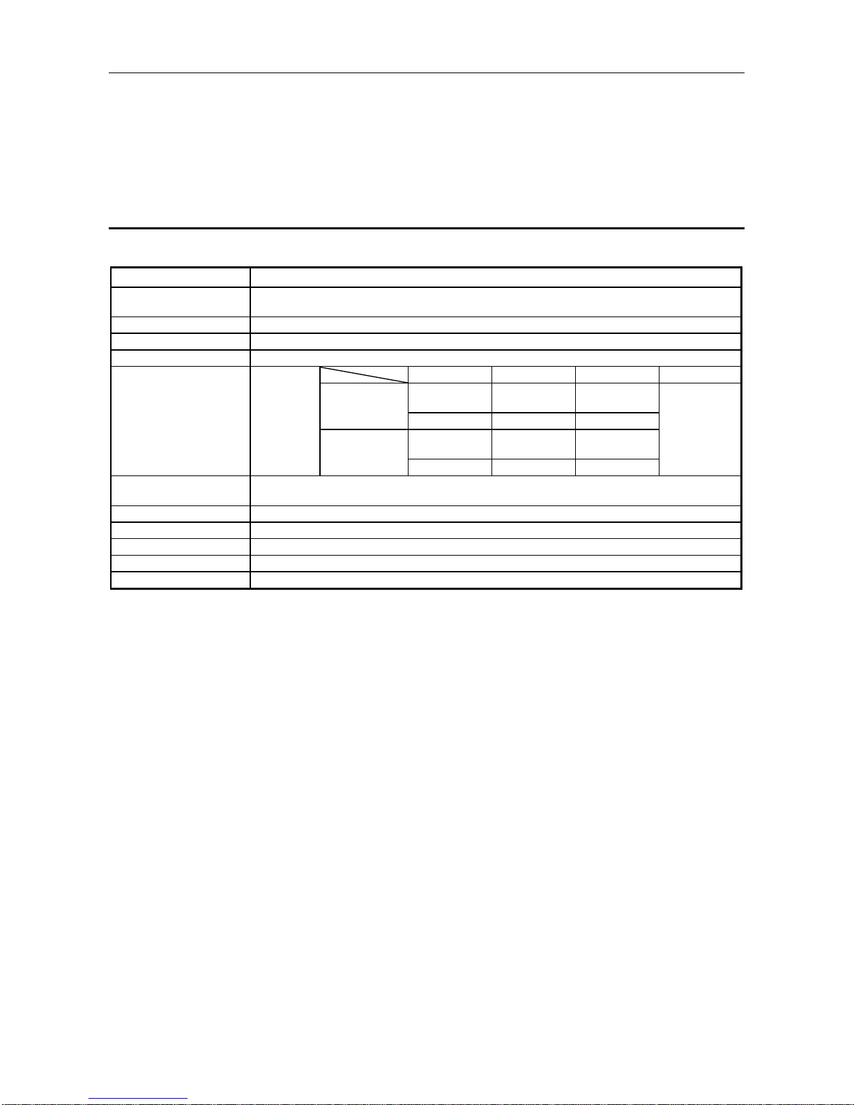
3.1 General Specification
This section explains the AJ65BT-68TD general specifications.
Item Specifications
Ambient operating
temperature
0 to 55
°C
Ambient storage temperature -20 to 75 °C
Ambient operating humidity 10 to 90 %RH, Non-condensing
Ambient storage humidity 10 to 90 %RH, Non-condensing
Frequency Acceleration Amplitude No. of sweeps
10 to 57 Hz —
0.075 mm
(0.0030 in.)
Vibration resistance 57 to 150 Hz 9.8 m/s2 {1 G} —
10 to 57 Hz —
0.035 mm
(0.0014 in.)
57 to 150 Hz 4.9 m/s2 {0.5 G} —
Shock resistance Conforming to JIS B 3502, IEC 61131-2
(147 m/s
2
{15 G}, 3 times in each of 3 directions X Y Z)
Operating ambience No corrosive gases
Operating elevation 2000 m (6562 ft.) max.
Installation location Control panel
Over voltage category *1 II max.
Pollution level *2 2 max.
*1 : This indicates the section of the power supply to which the equipment is assumed to be
connected between the public electrical power distribution network and the machinery within the
premises. Category II applies to equipment for which electrical power is supplied from fixed
facilities. The surge voltage withstand level for up to the rated voltage of 300 V is 2500 V.
*2 : This index indicates the degree to which conductive material is generated in terms of the
environment in which the equipment is used. Pollution level 2 is when only non-conductive
pollution occurs. A temporary conductivity caused by condensation must be expected
occasionally.
10 times each in
X, Y, Z directions
(for 80 min.)
Conforming to
JIS B 3502,
IEC 61131-2
Under intermittent
vibration
Under continuous
vibration
Page 16
3. SPECIFICATIONS MELSEC-A
3-2
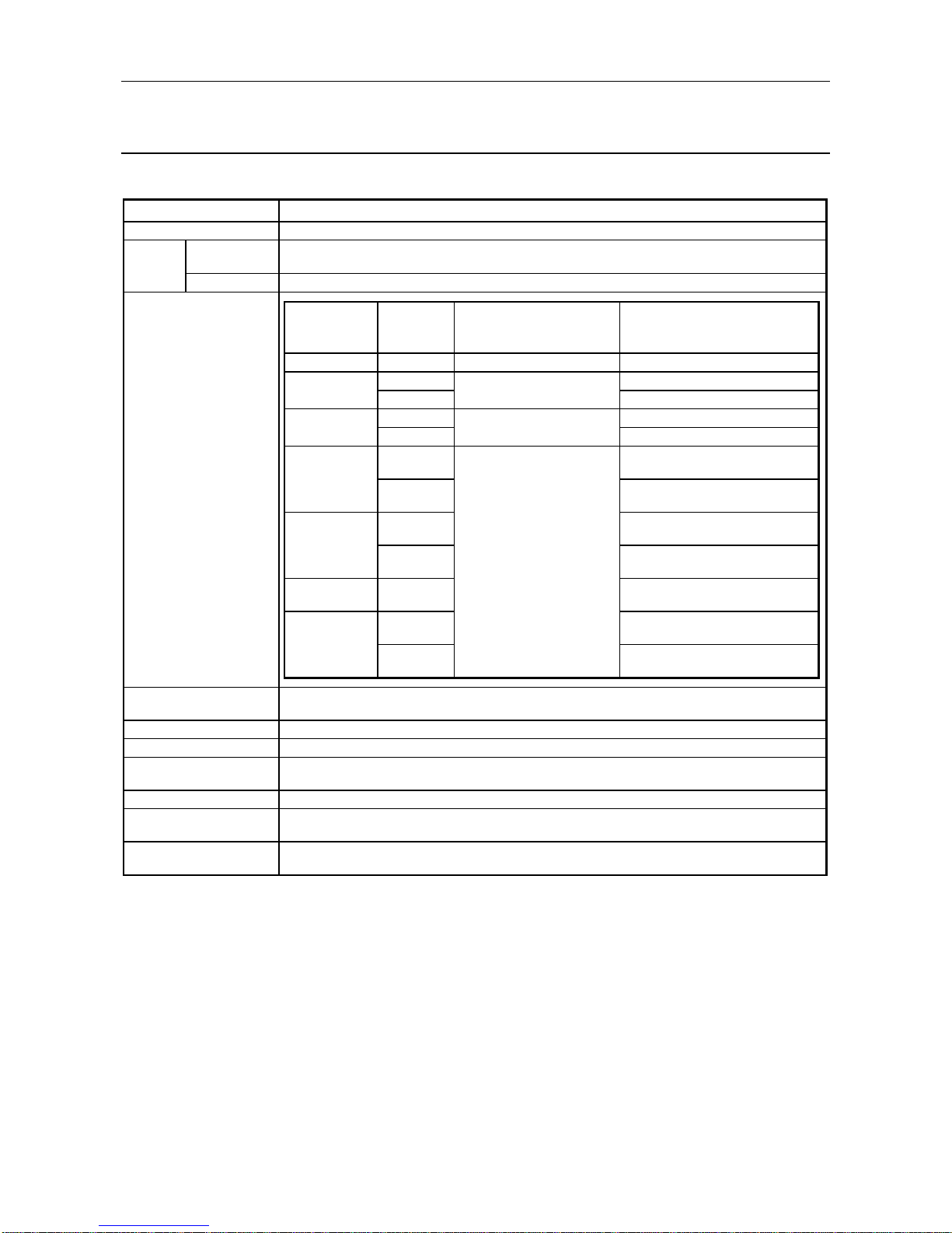
3.2 Performance Specifications
The performance specifications of the AJ65BT-68TD are shown below.
Item Specifications
Temperature Sensor Input (°C) -200 to 1700
Output
Detected
temperature
Scaling value 16-bit signed binary (0 to 2000)
Applicable thermocouples
and temperature
measurement range accuracy
Cold junction compensation
accuracy (°C)
Overall accuracy Depends on *1 calculation expression
Maximum resolution B, R, S : 0.3 °C K, E, J, T : 0.1 °C
Conversion speed
(sampling time) [ms/ch]
Absolute maximum input [V] ± 5
Number of analog input
points
8 channels + Pt100 connection channel
Thermocouple input to CC-Link transmission : Transformer insulation
Between channels : Transformer insulation
16-bit signed binary (-2000 to 17000 : value to one decimal place multiplied by 10)
± 1.0
45 ms/channel *2
Insulation method
Applicable
thermocouple
type
Temperature
measuremen
t range [°C ]
Conversion accuracy
(When ambient operating
temperature is 25 ±5 °C)
Temperature characteristic
(Per 1 °C of ambient operating
temperature change)
B 600 to 1700 ± 2.5 °C ± 0.4 °C
0 to 200 ± 0.4 °C
200 to 1600 ± 0.3 °C
0 to 200 ± 0.4 °C
200 to 1600 ± 0.3 °C
±0.06 °C or ±0.3 % of the measured
temperature, whichever is greater
±0.06 °C or ±0.02 % of the measured
temperature, whichever is greater
±0.06 °C or ±0.3 % of the measured
temperature, whichever is greater
±0.06 °C or ±0.02 % of the measured
temperature, whichever is greater
±0.06 °C or ±0.02 % of the measured
temperature, whichever is greater
±0.06 °C or ±0.3 % of the measured
temperature, whichever is greater
±0.06 °C or ±0.02 % of the measured
temperature, whichever is greater
±0.5 °C or ±0.25 % of the
measured temperature,
whichever is greater
± 2.0 °C
± 2.0 °C
0 to 350
-200 to 0
0 to 750
0 to 800
-200 to 0
-200 to 0
0 to 1200
S
T
J
E
K
R
Page 17

3. SPECIFICATIONS MELSEC-A
3-3
Item Specifications
CC-Link station type Remote device station
Number of occupied stations 4 Stations : RX/RY 128 points each RWw/RWr 16 points each
Transmission
speed/maximum
transmission distance
Refer to Section 3.4
Maximum number of
connected modules
Connection cable CC-Link dedicated cable
Depends on noise simulator of noise voltage at 500 Vp-p, noise width at 1 ms and noise
frequency at 25 to 60 Hz
Dielectric withstand voltage 500 V AC between DC external terminal batch and ground for 1 minute
10 MΩ or more using insulation resistance meter when 500 V DC between DC external
terminal batch and ground
Connected terminal block 27-point terminal blocks (M3.5 × 7 screws)
Applicable wire size [mm2] 0.75 to 2.00
Applicable solderless terminal RAV 1.25-3.5, RAV 2-3.5 (conforms to JIS C 2805)
Allowable momentary power
failure period [ms]
Screws M4 × 0.7 mm × 16 mm or larger (tightening torque range 78 to 118 N · cm {8 to 12 kg · cm})
May be attached using DIN rails
Applicable DIN rail TH35-7.5Fe, TH35-7.5AI, TH35-15Fe (conforms to JIS C 2812 )
External power supply 24V DC (18 to 30V DC)
Internal consumption current [A] 0.081
Mass [kg (lb)] 0.40 (0.88)
*1 Overall accuracy computation method is as follows:
(Overall accuracy) = (Conversion accuracy) + (Temperature characteristics) × (Ambient operating
temperature change) + (Cold junction compensation accuracy)
The ambient operating temperature change refers to the value that falls outside the range of 25 ±5 °C.
Example) The overall accuracy when using thermocouple K, measured temperature 150 °C,
ambient operating temperature 35 °C will be:
(±0.5 °C) + (±0.06 °C) × (5 °C) + (±1 °C) = ±1.8 °C
*2 Conversion speed is the time required to convert the input temperature to the corresponding digital
value and store it into the remote register.
When using multiple channels, the conversion speed becomes "45ms × number of channels that
are conversion enabled".
16 modules
1
Noise durability
Insulation resistor
Module installation screw
Page 18
3. SPECIFICATIONS MELSEC-A
3-4
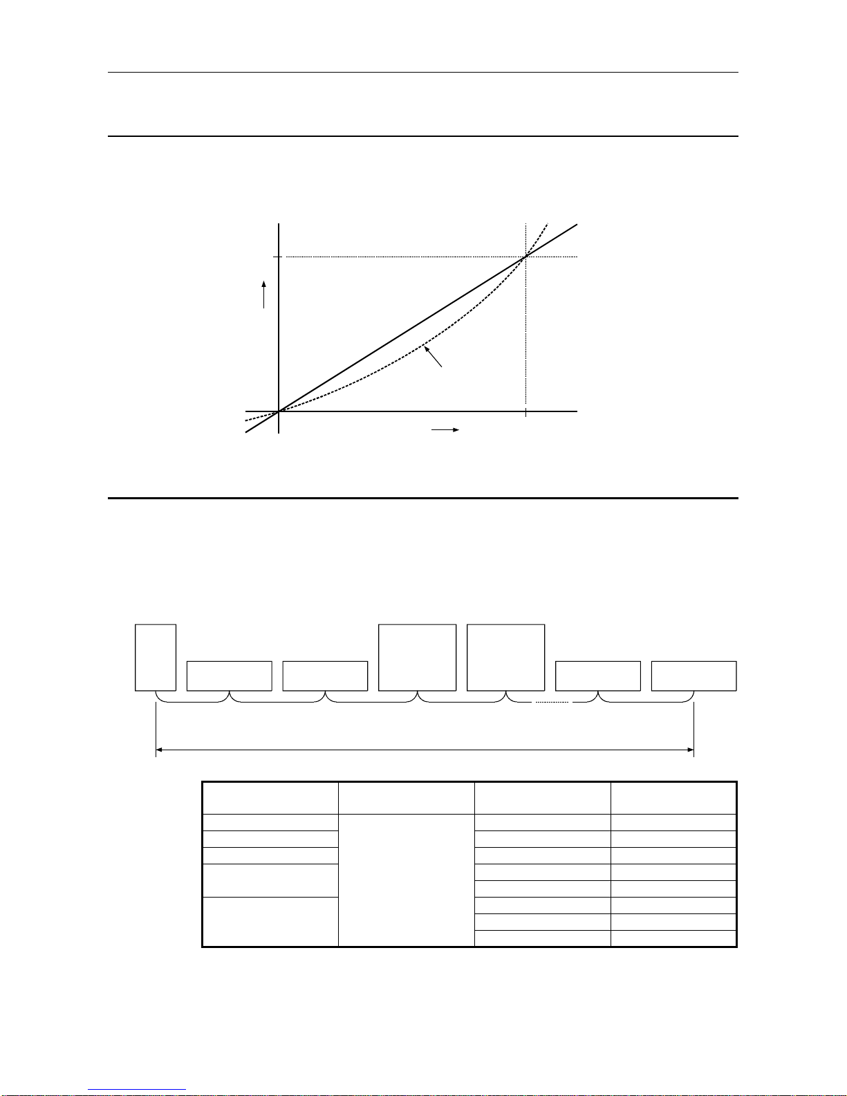
3.3 Temperature/Digital Conversion Characteristics
Since the thermal electromotive force has a non-linear characteristic, it must undergo the linearize
processing before being written in the remote register.
An example of detected temperature characteristic in respect to the thermocouple input value is shown
below.
(1200 °C) 12000
48828 [ µV ]
(1200 °C)
0
0
(0 °C)
(
0 °C
)
V
The diagram at left is an example
of temperature conversion
characteristic example under
the conditions shown below:
Thermocouple used : JIS K type
Terminal block temperature : 0 [°C]
T
e
m
p
e
r
a
t
u
r
e
c
o
n
v
e
r
s
i
o
n
v
a
l
u
e
Thermal
electromotive force
Thermocouple
output characteristic
3.4 Maximum Transmission Distance over the CC-Link System
The maximum transmission distance over the CC-Link system is shown below.
1) Regardless of the setting of the transmission speed, the cable length must be "greater than 2 m
(6.6 ft.)" long between a mater or local station, intelligent device station and the adjacent stations.
2) For 5 Mbps and 10 Mbps transmission speeds, the maximum transmission distance will differ
according to the cable length between the remote I/O station and remote device station, so
exercise caution.
Master
station
Remote I/O station
Remote device station
Remote I/O station
Remote device station
Remote I /O station
Remote device station
Remote I/O station
Remote device station
Local station
Standby master
station
Intelligent device
station
Local station
Standby master
station
Intelligent device
station
1) 1)2) 2)1)
Maximum transmission distance
Maximum transmission
distance
156 kbps 30 cm (11.8 in.) or more 1200 m (3937 ft.)
625 kpbs 30 cm (11.8 in.) or more 600 m (1968.5 ft.)
2.5 Mpbs 30 cm (11.8 in.) or more 200 m (656.2 ft.)
60 cm (23.6 in.) or more 150 m (492.1 ft.)
30 to 59 cm (11.8 to 23.2 in.) 110 m (360.9 ft.)
1 m (3.3 ft.) or more 100 m (328.1 ft.)
10 Mbps 60 to 99 cm (23.6 to 39 in.) 80 m (262.5 ft.)
30 to 59 cm (11.8 to 23.2 in.) 50 m (164 ft.)
2) 1) Transmission speed
2 m (6.6 ft.) or more 5 Mbps
Page 19

3. SPECIFICATIONS MELSEC-A
3-5
3.5 Data Link Processing Time
For the AJ65BT-68TD, the data link processing time shown below will be required in order to execute
each function.
For details on link scan time, refer to the AJ61BT11/A1SJ61BT11 CC-Link System Master/Local
Module User's Manual or the AJ61QBT11/A1SJ61QBT11 CC-Link System Master/Local Module
User's Manual.
(1) Mater station (RY) → Remote device station (RY) processing time
[Expression]
SM + LS × 3 + Remote device station processing time (90 ms)
[ms]
AJ65BT-68TD
SM : Master station sequence program scan time
LS : Link scan time
(2) Master station (RWw) → Remote device station (RWw) processing time
[Expression]
SM + LS × 3 + Remote device station processing time (90 ms)
[ms]
AJ65BT-68TD
SM : Master station sequence program scan time
LS : Link scan time
(3) Master station (RX) ← Remote Device Station (RX) Processing Time
[Expression]
SM + LS × 2 + Remote device station processing time (1 ms)
[ms]
AJ65BT-68TD
SM : Master station sequence program scan time
LS : Link scan time
(4) Master station (RWr) ← Remote Device Station (RWr) Processing Time
[Expression]
SM + LS × 2 + Remote device station processing time (1 ms)
[ms]
AJ65BT-68TD
SM : Master station sequence program scan time
LS : Link scan time
POINT
The above are examples of processing time until the control of the output signal to the AJ65BT68TD from the PLC CPU or until input signals or remote registers are read.
The maximum time that takes for updating the detected temperature read by the PLC CPU is
"data link processing time + sampling time."
Page 20
3. SPECIFICATIONS MELSEC-A
3-6
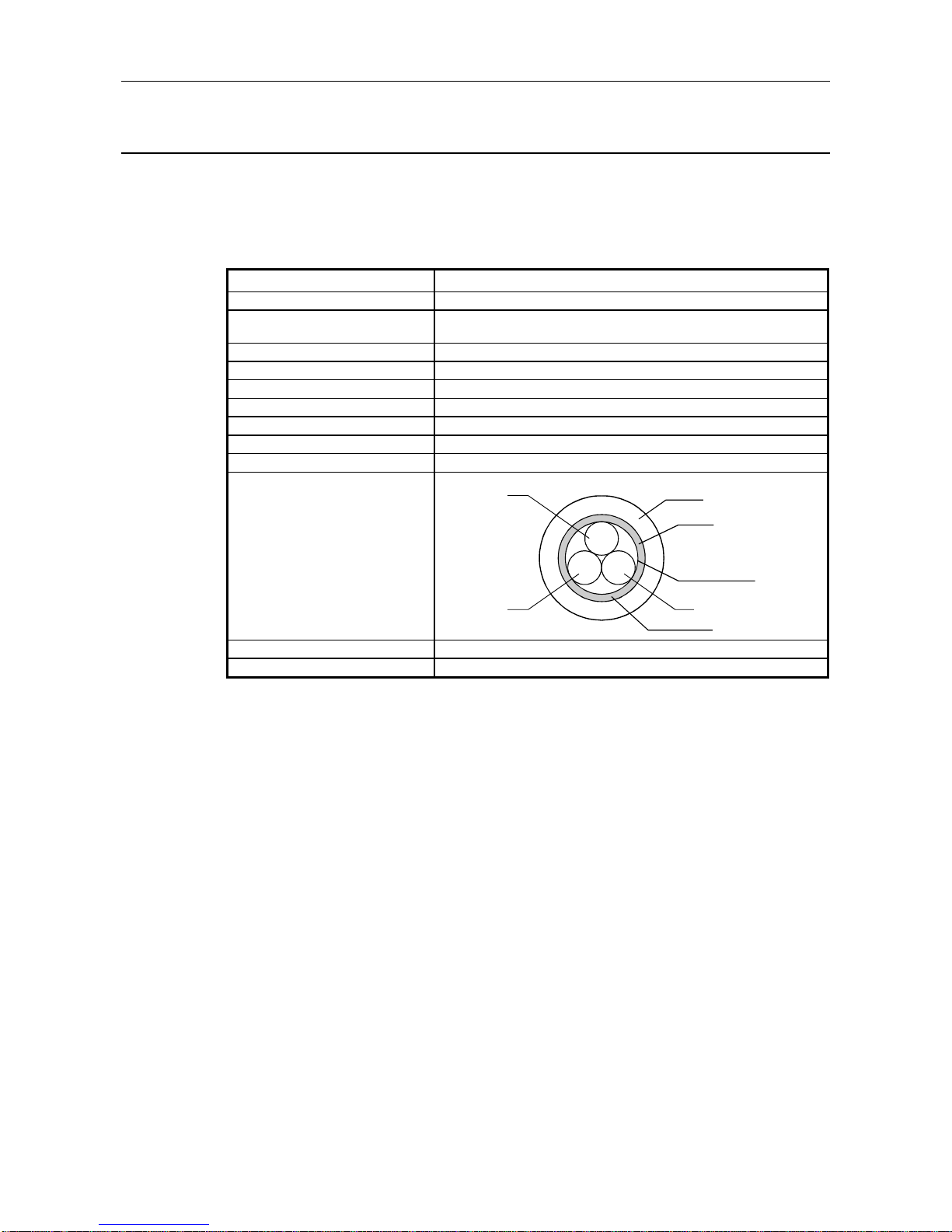
3.6 Twisted Cable Specifications
The twisted cable specifications and recommended cables for use with the CC-Link is explained
below.
Also, the performance of the CC-Link may not be guaranteed when using cables other than
recommended ones as shown below.
The recommended cable names and specifications are shown in the table below.
Item Specification
Type FANC–SB 0.5 mm2 × 3
Contact
Mitsubishi Electric System Service, Inc.
Kurashige Denkou, Inc.
Cable type Twisted shielded cable
Conductor cross-sectional area 0.5 mm2
Conductor resistance (20 °C) 37.8 Ω/km or less
Conductive resistance 10000 MΩ km or more
Dielectric withstand voltage 500 V DC one minute
Static capacity (1 kHz) 60 nF/km or less
Characteristic impedance (1 MHz) 100 ± 15 Ω
Cross-sectional diagram
blue
white yellow
DA
DB DG
Sheath
Shield
Aluminum tape
Ground wire
External dimensions 7 mm (0.28 in.)
Approximate mass 65 kg / km
Page 21

3. SPECIFICATIONS MELSEC-A
3-7
3.7 Function List
Below is a function list of the AJ65BT-68TD.
Item Description Reference section
Wire breakage detection
• Detects wire breakage for the connected thermocouple by
channel.
Section 3.8.3
Conversion enable/disable
designation
• Performs conversion enable/disable settings by channel.
• Sampling time may be reduced by disabling the conversion
at channels not in use.
Section 3.8.4
Sampling processing/travel
average processing designation
• Designates sampling processing or travel average
processing by channel.
Section 3.8.5
Thermocouple type selection
• The thermocouple type to be used may be set for each
channel or in batch.
Section 3.8.6
Pt100 cold junction
compensation enable/disable
designation
• Designates the Pt100 cold junction compensation
enable/disable.
• By disabling the Pt100 cold junction compensation, a highaccuracy ice bus is set outside of the module to increase
the cold junction compensation accuracy.
Section 3.8.7
Measured temperature
upper/lower limit value setting
• Sets the upper and lower limits of the measured
temperature by channel.
Section 3.9.2
Detected temperature storage
• A value to one decimal place (16-bit signed binary) will be
stored in the remote register.
Section 3.9.3
Scaling value storage
• The detected temperature value will be scaled to a value
of 0 to 2000 within the upper and lower limits and stored.
Section 3.9.4
Error compensation by
offset/gain value setting
• Error compensation is performed by setting the offset/gain
values.
Section4.4
Page 22

3. SPECIFICATIONS MELSEC-A
3-8
3.8 I/O Signals in Respect to the Master Module
The assignment of I/O signals and the functions is explained.
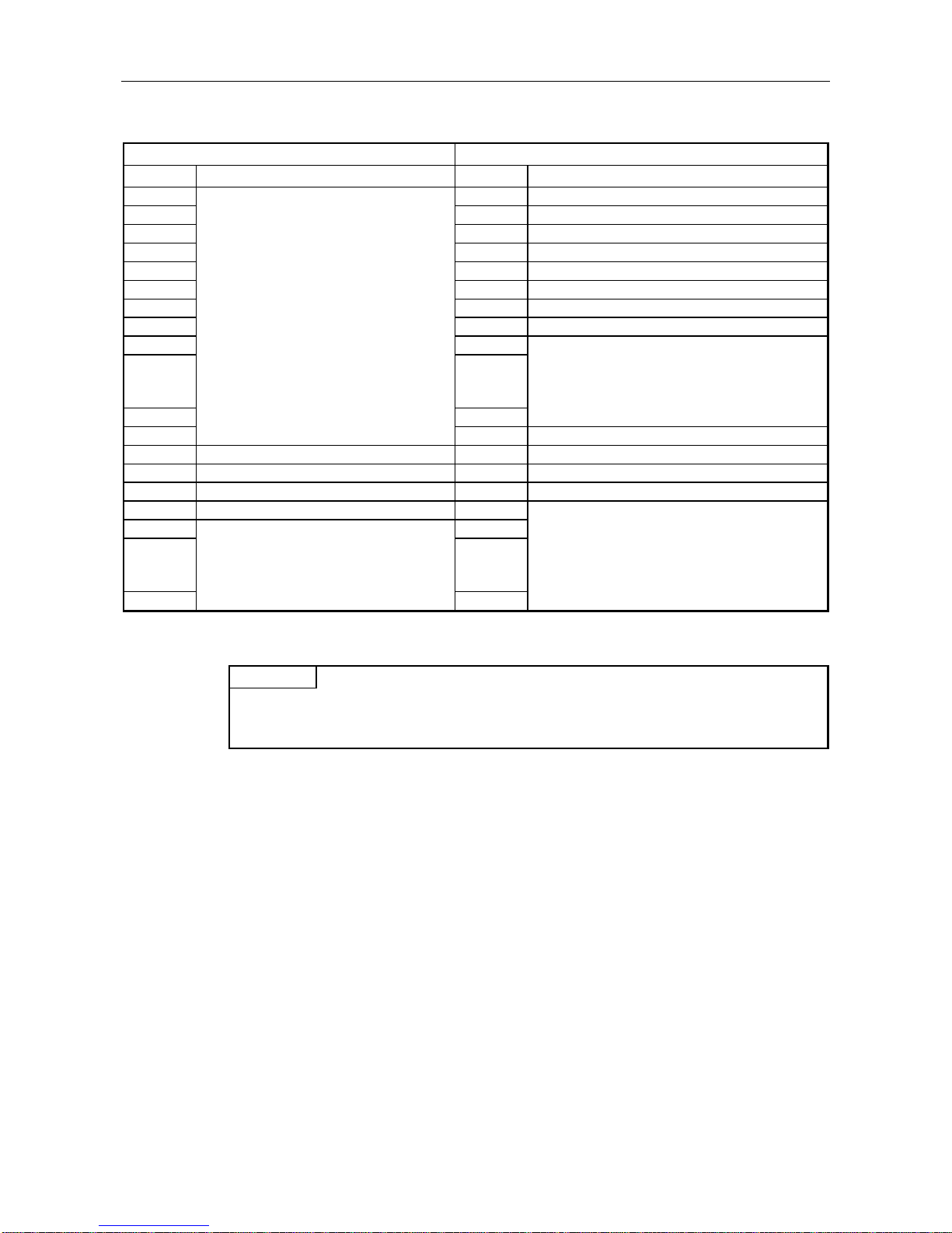
3.8.1 I/O signal list
The AJ65BT-68TD uses 128 points for input and 128 points for output in respect to the data for the
master module.
The I/O signal assignment and the name of each signal are shown in the table below.
Device RX indicates an input signal to the master module from the AJ65BT-68TD, and device RY
indicates an output signal from the master module to the AJ65BT-68TD.
Signal direction : AJ65BT-68TD → Master module Signal direction : Master module → AJ65BT-68TD
Device No. Signal name Device No. Signal name
RXn0 CH.1 conversion completion flag RYn0 CH.1 conversion enable flag
RXn1 CH.2 conversion completion flag RYn1 CH.2 conversion enable flag
RXn2 CH.3 conversion completion flag RYn2 CH.3 conversion enable flag
RXn3 CH.4 conversion completion flag RYn3 CH.4 conversion enable flag
RXn4 CH.5 conversion completion flag RYn4 CH.5 conversion enable flag
RXn5 CH.6 conversion completion flag RYn5 CH.6 conversion enable flag
RXn6 CH.7 conversion completion flag RYn6 CH.7 conversion enable flag
RXn7 CH.8 conversion completion flag RYn7 CH.8 conversion enable flag
RXn8 CH.1 wire breakage detection flag RYn8 CH.1 sampling/travel average processing designation flag
RXn9 CH.2 wire breakage detection flag RYn9 CH.2 sampling/travel average processing designation flag
RXnA CH.3 wire breakage detection flag RYnA CH.3 sampling/travel average processing designation flag
RXnB CH.4 wire breakage detection flag RYnB CH.4 sampling/travel average processing designation flag
RXnC CH.5 wire breakage detection flag RYnC CH.5 sampling/travel average processing designation flag
RXnD CH.6 wire breakage detection flag RYnD CH.6 sampling/travel average processing designation flag
RXnE CH.7 wire breakage detection flag RYnE CH.7 sampling/travel average processing designation flag
RXnF CH.8 wire breakage detection flag RYnF CH.8 sampling/travel average processing designation flag
RX (n+1) 0 CH.1 measurement range over flag (lower limit) RY (n+1) 0 CH.1 t ype "K" thermocouple selection flag
RX (n+1) 1 CH.1 measurement range over flag (upper limit) RY (n+1) 1 CH.1 type "E" thermocouple selection flag
RX (n+1) 2 CH.2 measurement range over flag (lower limit) RY (n+1) 2 CH.1 type "J" t hermoc ouple selection flag
RX (n+1) 3 CH.2 measurement range over flag (upper limit) RY (n+1) 3 CH.1 type "T" thermocouple selection flag
RX (n+1) 4 CH.3 measurement range over flag (lower limit) RY (n+1) 4 CH.1 t ype "B" thermocouple selection flag
RX (n+1) 5 CH.3 measurement range over flag (upper limit) RY (n+1) 5 CH.1 type "R" the rmo couple selection flag
RX (n+1) 6 CH.4 measurement range over flag (lower limit) RY (n+1) 6 CH.1 t ype "S" thermocouple selection flag
RX (n+1) 7 CH.4 measurement range over flag (upper limit) RY (n+1) 7 Use pro hibited
RX (n+1) 8 CH.5 measurement range over flag (lower limit) RY (n+1) 8 CH.2 t ype "K" thermocouple selection flag
RX (n+1) 9 CH.5 measurement range over flag (upper limit) RY (n+1) 9 CH.2 type "E" thermocouple selection flag
RX (n+1) A CH.6 measurement range over flag (lower limit) RY (n+1) A CH.2 type "J" t her moc ouple selection flag
RX (n+1) B CH.6 measurement range over flag (upper limit) RY (n+1) B CH.2 type "T" thermoc ouple selection flag
RX (n+1) C CH.7 measurement range over flag (lower limit) RY (n+1) C CH.2 type "B" thermocouple selection flag
RX (n+1) D CH.7 measurement range over flag (upper limit) RY (n+1) D CH.2 type "R" th erm ocouple selection flag
RX (n+1) E CH.8 measurement range over flag (lower limit) RY (n+1) E CH.2 type "S" thermocouple selection flag
RX (n+1) F CH.8 measurement range over flag (upper limit) RY (n+1) F Use pr ohibited
Page 23

3. SPECIFICATIONS MELSEC-A
3-9
Signal direction : AJ65BT-68TD → Master module Signal direction : Master module → AJ65BT-68TD
Device No. Signal name Device No. Signal name
RX (n+2) 0 CH.1 write data error flag RY (n+2) 0 CH.3 type "K" thermocouple selection flag
RX (n+2) 1 CH.2 write data error flag RY (n+2) 1 CH.3 type "E" thermocouple selection flag
RX (n+2) 2 CH.3 write data error flag RY (n+2) 2 CH.3 type "J" thermocouple selection flag
RX (n+2) 3 CH.4 write data error flag RY (n+2) 3 CH.3 type "T" thermocouple selection flag
RX (n+2) 4 CH.5 write data error flag RY (n+2) 4 CH.3 type "B" thermocouple selection flag
RX (n+2) 5 CH.6 write data error flag RY (n+2) 5 CH.3 type "R" thermocouple selection flag
RX (n+2) 6 CH.7 write data error flag RY (n+2) 6 CH.3 type "S" thermocouple selection flag
RX (n+2) 7 CH.8 write data error flag RY (n+2) 7 Use prohibited
RX (n+2) 8 E2PROM abnormal flag RY (n+2) 8 CH.4 type "K" thermocouple selection flag
RX (n+2) 9 Test mode flag RY (n+2) 9 CH.4 type "E" thermocouple selection flag
RX (n+2) A RY (n+2) A CH.4 type "J" thermocouple selection flag
RX (n+2) B RY (n+2) B CH.4 type "T" thermocouple selection flag
RX (n+2) C RY (n+2) C CH.4 type "B" thermocouple selection flag
RX (n+2) D RY (n+2) D CH.4 type "R" thermocouple selection flag
RX (n+2) E RY (n+2) E CH.4 type "S" thermocouple selection flag
RX (n+2) F RY (n+2) F Use prohibited
RX (n+3) 0 RY (n+3) 0 CH.5 type "K" thermocouple selection flag
RX (n+3) 1 RY (n+3) 1 CH.5 type "E" thermocouple selection flag
RX (n+3) 2 RY (n+3) 2 CH.5 type "J" thermocouple selection flag
RX (n+3) 3 RY (n+3) 3 CH.5 type "T" thermocouple selection flag
RX (n+3) 4 RY (n+3) 4 CH.5 type "B" thermocouple selection flag
RX (n+3) 5 RY (n+3) 5 CH.5 type "R" thermocouple selection flag
RX (n+3) 6 RY (n+3) 6 CH.5 type "S" thermocouple selection flag
RX (n+3) 7 RY (n+3) 7 Use prohibited
RX (n+3) 8 RY (n+3) 8 CH.6 type "K" thermocouple selection flag
RX (n+3) 9 RY (n+3) 9 CH.6 type "E" thermocouple selection flag
RX (n+3) A RY (n+3) A CH.6 type "J" thermocouple selection flag
RX (n+3) B RY (n+3) B CH.6 type "T" thermocouple selection flag
RX (n+3) C Use prohibited RY (n+3) C CH.6 type "B" thermocouple selection flag
RX (n+3) D RY (n+3) D CH.6 type "R" thermocouple selection flag
RX (n+3) E RY (n+3) E CH.6 type "S" thermocouple selection flag
RX (n+3) F RY (n+3) F Use prohibited
RX (n+4) 0 RY (n+4) 0 CH.7 type "K" thermocouple selection flag
RX (n+4) 1 RY (n+4) 1 CH.7 type "E" thermocouple selection flag
RX (n+4) 2 RY (n+4) 2 CH.7 type "J" thermocouple selection flag
RX (n+4) 3 RY (n+4) 3 CH.7 type "T" thermocouple selection flag
RX (n+4) 4 RY (n+4) 4 CH.7 type "B" thermocouple selection flag
RX (n+4) 5 RY (n+4) 5 CH.7 type "R" thermocouple selection flag
RX (n+4) 6 RY (n+4) 6 CH.7 type "S" thermocouple selection flag
RX (n+4) 7 RY (n+4) 7 Use prohibited
RX (n+4) 8 RY (n+4) 8 CH.8 type "K" thermocouple selection flag
RX (n+4) 9 RY (n+4) 9 CH.8 type "E" thermocouple selection flag
RX (n+4) A RY (n+4) A CH.8 type "J" thermocouple selection flag
RX (n+4) B RY (n+4) B CH.8 type "T" thermocouple selection flag
RX (n+4) C RY (n+4) C CH.8 type "B" thermocouple selection flag
RX (n+4) D RY (n+4) D CH.8 type "R" thermocouple selection flag
RX (n+4) E RY (n+4) E CH.8 type "S" thermocouple selection flag
RX (n+4) F RY (n+4) F Use prohibited
Page 24
3. SPECIFICATIONS MELSEC-A
3-10
Signal direction : AJ65BT-68TD → Master module Signal direction : Master module → AJ65BT-68TD
Device No. Signal name Device No. Signal name
RX (n+5) 0 RY (n+ 5) 0 All CH. batch type "K" thermocouple selection flag
RX (n+5) 1 RY (n+ 5) 1 All CH. batch type "E" thermocouple selection flag
RX (n+5) 2 RY (n+ 5) 2 All CH. batch type "J" thermocouple selection flag
RX (n+5) 3 RY (n+ 5) 3 All CH. batch type "T" thermocouple selection flag
RX (n+5) 4 RY (n+ 5) 4 All CH. batch type "B" thermocouple selection flag
RX (n+5) 5 RY (n+ 5) 5 All CH. batch type "R" thermocouple selection flag
RX (n+5) 6 Use pro hibited RY (n+ 5) 6 All CH. batch type "S" thermocouple selection flag
RX (n+5) 7 RY (n+5) 7 Pt100 cold junction compensation disable flag
RX (n+5) 8 RY (n+5) 8
to to Use prohibited
RX (n+7) 6 RY (n+7) 6
RX (n+7) 7 RY (n+7) 7 Offset/gain value selection flag
RX (n+7) 8 Initial data processing request flag RY (n+7) 8 Initial data processing completion flag
RX (n+7) 9 Initial data setting completion flag RY (n+7) 9 Initial data setting request flag
RX (n+7) A Error status flag RY (n+7) A Error reset request flag
RX (n+7) B Remote READY RY (n+7) B
RX (n+7) C RY (n+7) C
to Use prohibited to Use prohibited
RX (n+7) F RY (n+7) F
n : Addresses assigned to the master module by the station number setting.
POINT
Do not turn on the output signals that are prohibited in respect to the remote device from the
master module.
If the prohibited signals are output, the PLC system may malfunction.
Page 25

3. SPECIFICATIONS MELSEC-A
3-11
3.8.2 I/O signal functions
The function of each I/O signal for the AJ65BT-68TD is explained below.
(1) Input signal
Device No. Signal name Description
RXn0 to RXn7
CH.
conversion
completion flag
The conversion completion flag turns on when the detected temperature value
converted at each channel is stored in the remote register after power on or a
hardware reset.
If the travel average processing is running, it will turn on when the detected
temperature value is converted and stored in the remote register after the travel
average processing has completed. The conv ersion completion flag changes
according to the conditions listed below.
• When conversion disabled is changed to enabled
The temperature detection of the enabled channels will be commenced.
After the detected temperature values are stored in the remote register, the
conversion completion flag is turned on for the corresponding channel.
• When conversion enabled is changed to disabled
The conversion completion flag is turned off for the corresponding channel.
For the values stored in the remote register, the data immediately prior to the
disable setting are retained.
RXn8 to RXnF
CH.
wire
breakage
detection flag
For the thermocouple input circuit for all channels, when only a single section of the
I/O signal lines including the thermocouple is broken, the wire breakage detection flag
is turned on for the corresponding channel.
The detected temperature value when a wire breakage detection flag is turned on will
be maintained at the normal value immediately prior to the wire breakage, and then the
conversion completion flag will be turned off.
After the wire breakage has been removed, the wire breakage detection flag may be
turned off by turning on the error reset request flag.
Also, after the breakage has been fixed, the updating of detected temperatures value
will be resumed regardless of whether or not the wire breakage detection flag is reset,
and after the first update has been completed the conversion completion flag will turn
on once again.
CH.
measurement
range over flag
When a detected temperature value that falls outside of the upper and lower limits set
in the remote register is detected, the measurement range over flag is turned on for
the corresponding channel.
When the detected temperature value returns to inside the range, it is reset (off)
automatically.
RX (n+2) 1 to
RX (n+2) 7
CH.
writ e
data error flag
When a value exceeding the specification is written in the write-only area of the remote
register (upper and lower limit setting) or when multiple types of thermocouples are
selected in the thermocouple selection flag, the write data error is turned on for the
corresponding channel.
After the cause of the write data error has been removed, the flag may be turned off by
turning on the error reset request flag.
RX (n+2) 8
After power on or a hardware reset, the internal memory (E2PROM for offset/gain value
storage) is checked, and it turns on if there is an error.
At such times, the conversion function will stop.
When this flag turns on, the error reset request flag may not be used to reset (off)
because the module itself is malfunctioning (hardware error).
Turns on during test mode.
Turns off when reverted to normal mode.
RX (n+1) 1 to
RX (n+1) F
E
2
PROM
abnormal flag
Test mode flag RX (n+2) 9
Page 26

3. SPECIFICATIONS MELSEC-A
3-12
Device No. Signal name Description
After power on or a hardware reset, this is turned on because the AJ65BT-68TD
requests the initial data setting .
After the initial data processing is complete (initial data processing request flag
RY(n+7)8 is turned on), it turns off.
Turns on when initial data setting request (initial data setting request flag RY(n+7)9 is
turned on) is made.
After the initial data setting request flag is turned off when initial data setting is
complete, this also turns off.
RX (n+7) A
Turns on when wire breakage detection flag/write data error flag/E
2
PROM error flag
turns on.
After the cause of the error has been removed, the flag may be reset (off) by turning
on the error reset request flag, but since the E
2
PROM error flag cannot be reset, this
flag may also not be reset.
RX (n+7) B
After power on or a hardware reset, this flag turns on when the initial data setting is
complete and the detected temperature value at the conversion-enabled channel has
been stored in the remote register.
Will not turn on when all channels are conversion disabled.
It will turn off for two seconds when the offset/gain switch is set to [OFFSET] during
test mode or when changed from [GAIN] to [SET].
Used as an interlock for read and write in respect to the master module.
Initial data
processing
request flag
RX (n+7) 8
Initial data
setting
completion
flag
RX (n+7) 9
Error status
flag
Remote
READY
Page 27

3. SPECIFICATIONS MELSEC-A
3-13
(2) Output signal
Device No. Signal name Description
RYn0 to RYn7
CH.
conversion
enable flag
It is possible to designate the conversion enabled or disabled for each channel.
By disabling the conversion at channels not in use, generation of unnecessary wire
breakage detection flags may be prevented and sampling time may be reduced.
ON : Conversion enabled
.....
wire breakage detection is conducted at the same time
the temperature of the target object is taken.
OFF : Conversion disabled
....
neither temperature taking or wire breakage detection
is conducted.
By setting of conversion enable/disable, the following changes are made.
• When conversion is changed from disabled
→ enabled
Temperature detection of the enabled channel is commenced.
After the detected temperature value of the corresponding channel is stored in the
remote register, the conversion completion flag of the corresponding channel is
turned on.
• When the conversion is changed from enabled
→ disabled.
The conversion completion flag is turned off for the corresponding channel.
For the detected temperature value stored in the remote register, the data
immediately prior to the disable setting will be retained.
RYn8 to RYnF
CH.
sampling
processing/
travel average
processing
designation
flag
It is possible to designate the sampling processing or travel average processing for
each independent channel.
ON : Travel average processing
OFF : Sampling processing
In travel average processing, an average value of four detected temperature value
samples that were taken during each sampling time is calculated and stored in the
remote register.
• When changed from sampling processing
→ travel average processing
The conversion completion flag for the corresponding channel is turned off.
An average value of four detected temperature value samples is calculated, and
after it has been stored to the remote register the conversion completion flag of the
corresponding channel is turned on.
• When changed from travel average processing
→ sampling processing
The conversion completion flag is turned off for the corresponding channel.
After the most recent detected temperature value is stored in the remote register,
the conversion completion flag for the corresponding channel is turned on.
Note : This flag is only valid when the initial data processing completion flag (RY (n+7)
8) or initial data setting request flag (RY (n+7) 9) is on.
Page 28

3. SPECIFICATIONS MELSEC-A
3-14
Device No. Signal name Description
RY (n+1) 0
to
RY (n+1) 6
CH.1
thermocouple
selection flag
RY (n+1) 8
to
RY (n+1) E
CH.2
thermocouple
selection flag
RY (n+2) 0
to
RY (n+2) 6
CH.3
thermocouple
selection flag
RY (n+2) 8
to
RY (n+2) E
CH.4
thermocouple
selection flag
RY (n+3) 0
to
RY (n+3) 6
CH.5
thermocouple
selection flag
RY (n+3) 8
to
RY (n+3) E
CH.6
thermocouple
selection flag
RY (n+4) 0
to
RY (n+4) 6
CH.7
thermocouple
selection flag
RY (n+4) 8
to
RY (n+4) E
CH.8
thermocouple
selection flag
All CH.
batch
thermocouple
selection flag
All channels are selected to the same thermocouple in batch. This flag takes priority
over the thermocouple selection flag for individual channels. The thermocouple
selection flag for individual channels may only be used when this flag is off.
Also, when multiple batch thermocouple selection flags are turned on, the write data
error flag is turned on and the previously selected thermocouple type is retained.
Refer to the I/O signal list for the correspondence between each signal and
thermocouple type.
Note : This flag is only valid when the initial data processing compensation flag
(RY(n+7)8) or initial data setting request flag (RY (n+7) 9) is on.
RY (n+5) 7
The detected temperature value to be stored in the remote register can be selected
from a value that has undergone cold junction compensation by Pt100 temperaturemeasuring resistor, and a value that has not (the cold junction compensation is
performed externally).
ON : Cold contact compensation is not performed by the Pt100 temperature-
measuring resistor.
OFF : Cold contact compensation is performed by the Pt100 temperature-measuring
resistor.
Note : This flag is only valid when the initial data processing compensation flag
(RY(n+7)8) or initial data setting request flag (RY (n+7) 9) is on.
Selects the type of thermocouple to be connected to each channel.
Only the flags appropriate for the thermocouple to be used are turned on.
It is read as the set value when the initial data processing request flag is turned on.
When the flag is off after power on or a hardware reset, the K type is selected.
Also, when multiple thermocouple selection flags are turned on, the write data error flag
is turned on and the previously selected thermocouple type is retained.
Refer to the I/O signal list for the correspondence between each signal and
thermocouple type.
Note : This flag is only valid when the initial data processing compensation flag
(RY(n+7)8) or initial data setting request flag (RY (n+7) 9) is on.
RY (n+5) 0
to
RY (n+5) 6
Pt100 cold
junction
compensation
disable flag
Page 29

3. SPECIFICATIONS MELSEC-A
3-15
Device No. Signal name Description
Select whether or not the offset/gain value will be set to "user setting" or "factory
setting."
At the product shipment from factory, the same values for the factory settings are
stored in the E
2
PROM for storing the user setting offset/gain values.
ON : Factory setting (Offset-gain, 100.0
Ω (0 °C equivalent) -300 °C)
OFF : User setting
Note : This flag is only valid when the initial data processing compensation flag (RY
(n+7) 8) or initial data setting request flag (RY (n+7) 9) is on.
RY (n+7) 8
Initial data
processing
completion flag
After power on or hardware reset, the initial data are set in the module by turning this
flag on during the initial data processing request .
Used when designating sampling processing/travel average processing designation,
selecting offset/gain value, setting upper and lower limits, Pt100 cold junction
compensation enable/disable designation or selecting thermocouples.
Turned on when changing the initial values.
Used when designating sampling processing/travel average processing, selecting
offset/gain value, setting upper and lower limits, or Pt100 cold junction compensation
enable/disable designation.
Error reset
request flag
When this flag is turned on, the wire breakage detection flag/write data error flag are
reset (turned off), and the error status flags are reset at the same time. However, the
E
2
PROM error flag may not be reset (turned off) and therefore the error status flag will
remain on.
n : Address assigned to the master module by the station number setting.
RY (n+7) 7
Offset/gain
value selection
flag
RY (n+7) 9
Initial data
setting request
flag
RY (n+7) A
Page 30
3. SPECIFICATIONS MELSEC-A
3-16
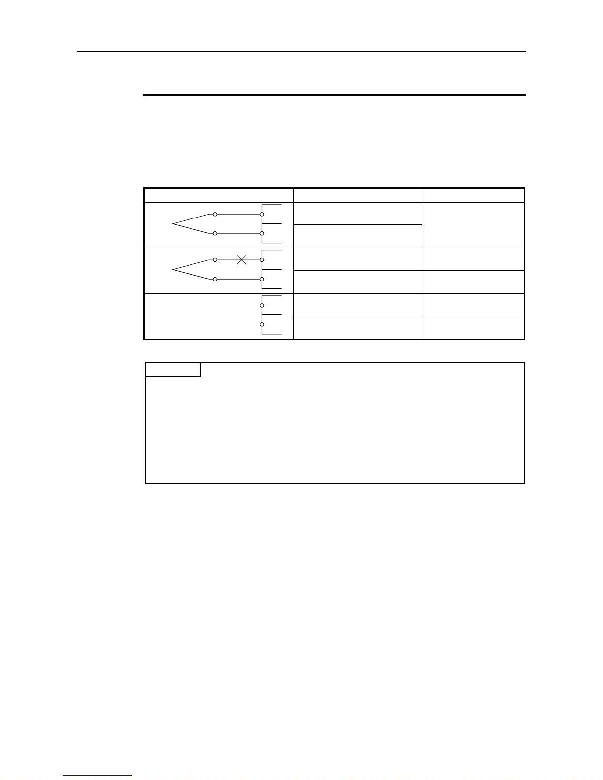
3.8.3 Wire breakage detection
The AJ65BT-68TD detects wire breakage in the thermocouple or compensating conductor used for
each channel, and turns on the wire breakage detection flag (RXn8 to RXnF) for the corresponding
channel.
On the AJ65BT-68TD, the wire breakage detection are performed for channels that are enabled for
conversion.
The relationships between the wire breakage detection and conversion enable/disable are shown
below.
Connection status Conversion enabled/disabled setting Wire breakage detection flag
Conversion enabled
Conversion disabled
Conversion enabled ON
Conversion disabled OFF
Conversion enabled ON
Conversion disabled OFF
POINT
• Be sure to set the channels having no thermocouple attached to "conversion disabled."
If a channel having no thermocouple attached is set to "conversion enabled," the wire
breakage detection flag will turn on.
• The channels for which wire breakage detection turned on will retain the normal detected
temperature value immediately prior to the breakage detection, and the conversion completion
flag for the corresponding channel will turn off.
When the detected breakage is fixed, updating of detected temperature value after repair will
be resumed and the conversion completion flag will be turned on again.
• For thermocouple wiring details, refer to Section 4.7.
+
–
No breakage
+
–
Breakage
+
–
No connection
OFF
Page 31

3. SPECIFICATIONS MELSEC-A
3-17
3.8.4 Conversion enable/disable designation
Conversion may be enabled or disabled for each channel individually.
The setting of the conversion is made through the CH.
conversion enable flags (RYn0 to RYn7).
Setting Description
ON Wire breakage detection is conducted at the same time the temperature of the target object is taken.
OFF Neither temperature detection nor wire breakage detection is conducted.
AJ65BT-68TD
ONRYn0
RYn1
RYn2
RYn3
to
ON
OFF
OFF
265RWrn
RWrn+1
RWrn+2
RWrn+3
to to to
1032
0
0
356RWrn+8
RWrn+9
RWrn+10
RWrn+11
to
1532
0
0
Enables conv ersion
for CH. 1
Enables conv ersion
for CH. 2
Disable conversion
for CH. 3
Disable conversion
for CH. 4
CH. 1 scaling value
CH. 2 scaling value
CH. 3 scaling value
CH. 4 scaling value
CH. 1 detected temperature
value
CH. 2 detected temperature
value
CH. 3 detected temperature
value
CH. 4 detected temperature
value
Remote I/O signal Remote register
(1) Relationship between conversion enable/disable designation and sampling time
By disabling conversion at the channels not in use, sampling time may be reduced.
<If all channels are conversion enabled>
45 ms × 8 channels = 360 ms
(= sampling time)
<If only one channel is conversion enabled>
45 ms × 1 channel = 45 ms (= sampling time)
(2) Changes caused by switching conversion enable/disable designation
<When changed from conversion disabled → enabled>
Sampling of the enabled channels will be commenced.
After the detected temperature values are stored in the remote register, the conversion
completion flag is turned on for the corresponding channel.
<When changed from conversion enabled → disabled>
Sampling of the disabled channels will be stopped.
The conversion completion flag is turned off for the corresponding channel.
For the detected temperature value stored in the remote register, the data immediately prior to
the disable setting will be retained.
Page 32

3. SPECIFICATIONS MELSEC-A
3-18
3.8.5 Sampling processing/travel average processing designation
The AJ65BT-68TD may designate sampling processing or travel average processing for each
individual channel.
The setting of sampling processing or travel average processing is made through the CH.
sampling
processing/travel average processing designation flags (RYn8 to RYnF).
Setting Description
ON Travel average processing
OFF Sampling processing
(1) Travel average processing
The average of the four detected temperature values that have been taken during each sampling
time (current value + three previous values) is calculated and stored in the remote register.
Also, since the average processing travels for each sampling, the most recent measured
temperature value may be obtained.
By using this, a scaling value can be obtained using the detected temperature value that has
undergone the average processing and stored in the remote register.
4
+++
4
+++
4
+++
1st storage
1st storage 2nd storage 3rd storage
2nd storage
3rd storage
The data transition inside the remote register
Sampling time
T
e
m
p
e
r
a
t
u
r
e
[°C]
Time [ms]
Remote register
Detected
temperature
value
Page 33

3. SPECIFICATIONS MELSEC-A
3-19
(2) Sampling processing
Stores the detected temperature value and scaling value are stored in the remote register by
each sampling time.
1st storage
1st storage 2nd storage 3rd storage
2nd storage
3rd storage
The data transition inside the remote register
Sampling time
T
e
m
p
e
r
a
t
u
r
e
[°C]
Time [ms]
Remote register
Detected
temperature
value
(3) Changes caused by altering sampling processing/travel average processing settings
<When changed from sampling processing → travel average processing>
The conversion completion flag is turned off for the corresponding channel.
After an average of four previously detected temperature values is calculated and stored to the
remote register, the conversion completion flag for the corresponding channel is turned on.
<When changed from travel average processing → sampling processing>
The conversion completion flag is turned off for the corresponding channel.
After the most recent detected temperature value is stored in the remote register, the conversion
completion flag for the corresponding channel is turned on.
Page 34

3. SPECIFICATIONS MELSEC-A
3-20
3.8.6 Thermocouple type selection
The AJ65BT-68TD can select the thermocouple to use for individual channels or all channels in batch.
(1) When selecting the thermocouple to use for individual channels
The CH.
"K" to "S" type thermocouple selection flags are used to select the thermocouple used
for each channel.
Only the flags corresponding to the thermocouple used at each channel are turned on.
The CH.
"K" to "S" type thermocouple selection flags are valid only when the all-channel batch
"K" to "S" type thermocouple selection flag shown below is not selected.
Example) When selecting "S" type for the thermocouple used at CH. 1.
CH. type "K" to "S" thermocouple selection flag Signal description
CH.1 "K" type thermocouple selection flag
CH.1 "E" type thermocouple selection flag
CH.1 "J" type thermocouple selection flag
CH.1 "T" type thermocouple selection flag
CH.1 "B" type thermocouple selection flag
CH.1 "R" type thermocouple selection flag
CH.1 "S" type thermocouple selection flag ON
(2) When selecting a thermocouple for all channels in batch
The all-channel batch "K" to "S" type thermocouple selection flag is used to select types of
thermocouple to be used by all channels in batch.
Only the flags corresponding to the thermocouple to be used are turned on.
This takes priority over the CH.
"K" to "S" type thermocouple selection flag described above.
POINT
When multiple thermocouple selection flags are turned on with both the CH. "K" to "S" type
thermocouple selection flag and all-channel batch "K" to "S" type thermocouple selection flag, the
write data error flag turns on. At the same time, the error status flag will turn on and the
previously selected thermocouple types will be retained.
OFF
Page 35

3. SPECIFICATIONS MELSEC-A
3-21
3.8.7 Pt100 cold junction compensation enable/disable designation
The AJ65BT-68TD can designate the enabling/disabling of the cold junction compensation by the
Pt100 temperature-measuring resistor.
By designating the enabling/disabling of the cold junction compensation by the Pt100 temperaturemeasuring resistor, the detected temperature value to be stored in the remote register may be
switched between the value obtained using the Pt100 temperature-measuring resistor and not using
the Pt100 temperature-measuring resistor (when performing cold junction compensation externally).
The enabling/disabling of cold junction compensation by the Pt100 temperature-measuring resistor is
performed using the Pt100 cold junction compensation disable flag (RY (n+5) 7).
Setting Description
ON Do not use the Pt100 temperature-measuring resistor for cold junction compensation.
OFF Use the Pt100 temperature-measuring resistor for cold junction compensation.
(1) When using the Pt100 temperature-measuring resistor for cold junction compensation
The cold junction compensation is automatically performed by using the Pt100 temperaturemeasuring resistor supplied with the AJ65BT-68TD.
Pt100
AJ65BT-68TD
Compensating conductor (copper)
Temperature measurement targe
t
Thermocouple
(2) When performing cold junction compensation externally
Perform the following when the cold junction compensation accuracy (±1 °C) by the Pt100
temperature-measuring resistor supplied with the AJ65BT-68TD may not be ignored as a
tolerance. Since the module may be guided without any change in thermal electromotive force
generated at the tip of the thermocouple, the cold junction compensation accuracy may be
increased by installing a high accuracy temperature controller based upon 0°C* to outside of the
module.
* The temperature controller based upon 0°C has a structure in which a thermocouple and lead
wire are connected inside a pot, inside of which is maintained at 0°C.
Therefore, the thermal electromotive force generated at the contact point of the thermocouple
and contact area of the lead wire is 0 V, preventing the excess thermal electromotive force that
leads to errors in readings.
AJ65BT-68TD
Compensating conductor (copper)
Temperature measurement targe
t
Thermocouple
Temperature controller
based upon 0°C
Page 36

3. SPECIFICATIONS MELSEC-A
3-22
3.9 Remote Register
The AJ65BT-68TD is equipped with remote registers for data communication with the master module.
The assignment and data structure of the remote register are explained below.
3.9.1 Remote register assignment
The remote register assignments are shown in the table below.
Communication
direction
Reference
section
RWwm CH. 1 lower limit value (0.1 °C units)
RW wm+1 CH. 1 upper limit value (0.1 °C units)
RWwm+2 CH. 2 lower limit value (0.1 °C units)
RW wm+3 CH. 2 upper limit value (0.1 °C units)
RWwm+4 CH. 3 lower limit value (0.1 °C units)
RW wm+5 CH. 3 upper limit value (0.1 °C units) Measured
RW wm+6 CH. 4 lower limit value (0.1 °C units) temperature
RW wm+7 CH. 4 upper limit value (0.1 °C units) range for the Section
RW wm+8 CH. 5 lower limit value (0.1 °C units) currently 3.9.2
RW wm+9 CH. 5 upper limit value (0.1 °C units) selected
RWwm+10 CH. 6 lower limit value (0.1 °C units) thermocouple
RWwm+11 CH. 6 upper limit value (0.1 °C units)
RWwm+12 CH. 7 lower limit value (0.1 °C iunits)
RWwm+13 CH. 7 upper limit value (0.1 °C units)
RWwm+14 CH. 8 lower limit value (0.1 °C units)
RWwm+15 CH. 8 upper limit value (0.1 °C units)
RWrn CH. 1 detected temperature value(0.1 °C units)
RWrn+1 CH. 2 detected temperature value(0.1 °C units)
RWrn+2 CH. 3 detected temperature value(0.1 °C units)
RWrn+3 CH. 4 detected temperature value(0.1 °C units) Section
RWrn+4 CH. 5 detected temperature value(0.1 °C units) 3.9.3
RWrn+5 CH. 6 detected temperature value(0.1 °C units)
RWrn+6 CH. 7 detected temperature value(0.1 °C units)
RWrn+7 CH. 8 detected temperature value(0.1 °C units)
RWrn+8 CH. 1 scaling value
RWrn+9 CH. 2 scaling value
RWrn+10 CH. 3 scaling value
RWrn+11 CH. 4 scaling value Section
RWrn+12 CH. 5 scaling value 3.9.4
RWrn+13 CH. 6 scaling value
RWrn+14 CH. 7 scaling value
RWrn+15 CH. 8 scaling value
m,n : Address assigned to the master module by the station number setting
Default value Description Address
Master
→
Remote
Remote
→
Master
0
Page 37

3. SPECIFICATIONS MELSEC-A
3-23
3.9.2 High and low limit settings
The AJ65BT-68TD can set the measured temperature range (upper and lower limits) for each channel
to the remote register (RWwm to RWwm+15)
The value of the detected temperature value range for the thermocouple set by the thermocouple
selection flag is used by default.
However, since this is a write-only remote register, the set upper and lower limit values cannot be
read.
(1) Upper and lower limit value setting range
Default value
Lower limit Upper limit
K -2000 12000 -2000 to 12000
E -2000 8000 -2000 to 8000
J 0 7500 0 to 7500
T -2000 3500 -2000 to 3500
B 6000 17000 6000 to 17000
R 0 16000 0 to 16000
S 0 16000 0 to 16000
(2) Setting/changing methods for the upper and lower limit values
• When setting the upper and lower limits
After writing desired values to the remote register, perform power on or hardware reset. The
values are set when the initial data processing request flag turns on.
After the changes, turn on the initial data processing completion flag.
• Changing the upper and lower limits
After writing desired values to the remote register, the values are changed by turning on the
initial data setting request flag.
After the changes, the initial data setting completion flag will turn on.
POINT
• If the measured values are not within the upper and lower limit range, the measurement range
over flag is turned on for the corresponding channel.
When the detected temperature value returns to within the upper and lower limit range, the
measurement range over flag is reset (turned off) automatically.
• When a value outside the measured temperature range is written, or the values for upper and
lower limits are switched (upper limit value ≤ lower limit value), a setting error occurs and a
write data error flag is turned on for the corresponding channel. At the same time, the error
status flag is turned on.
Thermocouple type
Possible upper and lower limit
value setting range
Page 38

3. SPECIFICATIONS MELSEC-A
3-24
3.9.3 Detected temperature value
The measurable temperature range for the AJ65BT-68TD is between -200 °C and 1700 °C.
The temperature read by each channel is converted to a detected temperature value that has
undergone the linearize processing and cold junction compensation, and stored to the remote register.
The detected temperature value is measured to one decimal place and multiplied by 10, then stored
as a 16-bit signed BIN data.
If the detected temperature value is negative, it is stored as a complement of 2.
<When the detected temperature value is 123.025 [°C]
.......
1230 is stored.>
b15 b14 b13 b12 b11 b10 b9 b8 b7 b6 b5 b4 b3 b2 b1 b0
0 0 0 0 0 1 0 0 1 1 0 0 1 1 1 0
<When the detected temperature value is -123.025 [°C]
......
-1230 is stored.>
b15 b14 b13 b12 b11 b10 b9 b8 b7 b6 b5 b4 b3 b2 b1 b0
1 1 1 1 1 0 1 1 0 0 1 1 0 0 1 0
3.9.4 Scaling value
The detected temperature value will be scaled to a value of 0 to 2000 within the set upper and lower
limit range, and stored.
The scaling value is stored as a 16-bit signed BIN data. Also, when processing the travel average, the
scaling value will be travel-averaged.
<When the scaling value is 1230
........
1230 is stored.>
b15 b14 b13 b12 b11 b10 b9 b8 b7 b6 b5 b4 b3 b2 b1 b0
0 0 0 0 0 1 0 0 1 1 0 0 1 1 1 0
The calculation method for scaling value is shown below.
Scaling value = ––———––—––—————––———––——––——– × 2000
Example) If the high and low value setting range for the measured temperature of CH1 is 0 °C to
2000 °C (lower limit 0, upper limit 12000) and 100 °C (detected temperature value 1000) is
to be scaled:
Scaling Value = –————— × 2000 = 166.6
···
The first decimal digit
will be rounded.
= 167
Stored in the remote
register.
Detected temperature value – Lower limit value
Upper limit value – Lower limit value
1000 – 0
1200 – 0
Page 39

4. SETTING AND PROCEDURE BEFORE OPERATION MELSEC-A
4-1
4. SETTING AND PROCEDURE BEFORE
OPERATION
The procedure before operation of AJ65BT-68TD, part identification and setting, and the wiring
method are explained below.
4.1 Procedure before Operation
The procedure before operation of AJ65BT-68TD is explained below.
························· Refer to Section 4.2, 4.6
························· Refer to Section 4.3
························· Refer to Section 4.7
························· Refer to Chapter 5
Start
Connect the supplied Pt100 temperature-measuring
resistor to the RTD terminal on the terminal block.
Set the switches listed below on AJ65BT-68TD.
• Statio n number settin g switch
• Transmission baud rate setting switch
Install the AJ65BT-68TD.
Connect cables to the AJ65BT-68TD.
Programming
End
Page 40

4. SETTING AND PROCEDURE BEFORE OPERATION MELSEC-A
4-2
4.2 Handling Precautions
The handling precautions for AJ65BT-68TD is explained below.
CAUTION
• The module should be fixed securely with a DIN rail or installation screws, and then
make sure to tighten it within the range of the specified torque of the instalation
screws.
If the screws are loose, it may result in fallout or malfunction.
Tightening the screws too far may cause damages to the screws and/or the module,
resulting in fallout or malfunction.
• Do not directly touch the module's conductive parts.
Doing so could cause malfunction or trouble in the module.
• Tighten the terminal screws within the range of specified torque.
If the terminal screws are loose, it may result in short circuit or malfunction.
Tightening the terminal screws too far may cause damage to the screws and/or the
module, resulting in short circuit or malfunction.
• Be sure there are no foreign substances such as sawdust or wiring debris inside the
module.
Such debris could cause fire, failure or malfunction.
• Do not touch the terminals while the power is on.
Doing so may cause malfunction.
• Do not disassemble or modify the module.
Doing so could cause failure, malfunction, injury or fire.
• Do not drop or give a strong shock to the module because its case is made of resin.
Doing so may cause a damage to the module.
• Make sure to switch all phases of the external power supply off before mounting or
removing the module.
If you do not switch off the external power supply, it will cause failure or malfunction
of the module.
• When disposing of this product, treat it as an industrial waste.
(1) Tighten the module terminal screws and fixing screws within the following torque range.
Screw area Tightening torque range
Module installation screws (M4 screw) 78 to 118 N · cm (8 to 12 kg · cm)
Terminal block terminal screws (M3.5 screw) 59 to 88 N · cm (6 to 9 kg · cm)
Terminal bolck installation screws (M4 screw) 98 to 137 N · cm (10 to 14 kg · cm)
(2) W hen using a DIN rail adapter, install the DIN rail considering the precautions described below.
(a) Applicable DIN rail types (conform to JIS C 2812)
TH35-7.5Fe
TH35-7.5Al
TH35-15Fe
(b) Space between DIN rail installation screws
When installing a DIN rail, tighten the screws with a space of less than 200 mm (7.9 in.).
Page 41

4. SETTING AND PROCEDURE BEFORE OPERATION MELSEC-A
4-3
4.3 Part Identification and Setting
The part identification and setting method for AJ65BT-68TD is explained below.
MITSUBISHI
AJ65BT-68TD
X10 X1
STATION NO.B RATE
MODE OFFSET UP
GAIN DOWN
RESET
PW
RUN
L RUN
SD
RD
L ERR.
MELSEC
0
1
2
3
456
7
8
9
0
1
2
3
456
7
8
9
0
1
2
3
456
•
•
• 01
2
3
4• •
•
•
•
SET
SW MODE
NORMAL
TEST CH.
TEST
0
1-8
9
2) 1)
6)
5)
9)
4
)3)7)8)
No. Name Description
1)
Station setting
switch
10 1
STATION NO.
0
1
2
3
456
7
8
9
0
1
2
3
456
•
•
•
Sets the station number of AJ65BT-68TD in the range of 1 to 61.
" × 10" sets the ten's place for a station number.
" × 1" sets the one's place for a station number.
(Factory setting : 0)
2)
Transmission
baud rate
setting switch
B RATE
0
1
2
3
4• •
•
•
•
Sets the transmission speed of AJ65BT-68TD (for data link).
3)
Mode switch
MODE
0
1
2
3
456
7
8
9
4)
Offset/gain
setting switch
OFFSET
GAIN
SET
Setting No. Transmission baud rate
0 156 kbps (factory setting)
1 625 kbps
2 2.5 Mbps
3 5 Mbps
4 10 Mbps
Unused (if a number other than 0 to 4 is used, the "L. ERR" LED is lit and
communication error occurs.)
During a normal operation, select this to end the test mode.
(Factory setting)
1 to 8 TEST CH. At a test mode, select a channel to perform error compensation.
9 TEST When executing error compensation, select TEST to enter the test mode after 2 seconds.
OFFSET Compensation mode of offset value
GAIN Compensation mode of gain value
SET
Store the detected temperature value when the position is switched from
OFFSET/GAIN to SET as an offset value/gain value, in the internal memory of AJ65BT68TD.
Other than 0 to 4
NORMAL 0
Page 42

4. SETTING AND PROCEDURE BEFORE OPERATION MELSEC-A
4-4
No. Name Description
5)
UP/DOWN
switch
UP
DOWN
Increase/decrease the offset value/gain value of the channel selected by the mode switch.
ON for less than 1.5 seconds : increase/decrease 0.025 °C at a time.
ON for more than 1.5 seconds : increase/decrease 0.1 °C per 0.04 seconds.
6)
Reset switch
RESET
Hardware reset
Initialize the remote register and operation processing of AJ65BT-68TD.
The initial data processing request flag turns on by turning the switch on.
7)
LED for
operation
status display
PW
RUN
L RUN
SD
RD
L ERR.
8)
Terminal block
13579111315171921232527
2468101214161820222426
DA DG
DB SLD (FG)
+24V 24G
CH8+CH7+CH6+CH5+CH 4+CH3+CH2+CH1+
RTDRTD
CH8-CH7-CH6-CH5-CH4-CH3-CH2-CH1-
9)
Temperature
measuring
resistor Pt 100
The temperature-measuring resistor to measure the terminal block temperature. (Supplied with the module)
ON : Power is on
OFF : Power is off
Normal
mode
ON : Normal operation
Flicker : Read data error occurred
OFF : 24 V DC power failure or WDT error
RUN
Test mode
Flickers : When the offset/gain setting switch is set at OFFSET or GAIN
Flickers at 0.5-second intervals during normal error compensation
Flickers at 0.1-second intervals when the following invalid error compensation has
been attempted:
• A temperature conversion value out of the temperature input range was set.
• Setting was made so that the gain value minus the offset value is smaller
than + 10°C.
∗ In this case, the offset or gain value will not be set even if the offset/gain
setting switch is set at SET.
OFF: The offset/gain setting switch is set at SET
ON : Normal communication
OFF : Communication disconnected (time over error)
SD Turns on during data transmission
RD Turns on during data receiving
ON : Communication data error (CRC error)
Station number, baud rate switch setting error
Flicker : Station number or baud rate switch is changed
OFF : Normal communication
L ERR.
PW
L RUN
Page 43

4. SETTING AND PROCEDURE BEFORE OPERATION MELSEC-A
4-5
4.4 Error Compensation by the Offset Value/Gain Value Setting
The AJ65BT-68TD error compensation is a function that compensates values at arbitrary 2 points
(offset value/gain value) within the usage temperature range at system startup or when a correct
temperature cannot be detected.
The error compensation is executed by reading the detected temperature value in the remote register
using a sequence program and monitoring the values using a peripheral device.
X10 X1
STATION NO.B RATE
MODE OFFSET UP
GAIN DOWN
RESET
PW
RUN
L RUN
SD
RD
L ERR.
0
1
2
3
456
7
8
9
0
1
2
3
456
7
8
9
0
1
2
3
456
•
•
• 01
2
3
4• •
•
•
•
SET
SW MODE
NORMAL
TEST CH.
TEST
0
1-8
9
OFFSET GAIN
<
Lower value of the two
points to be compensated
Higher value of the two
points to be compensated
UP/DOWN adjustment of OFFSET/GAIN
The following shows the characteristic of detected temperature value with respect to the input
temperature.
80 [°C]
80 [°C]0
-50 [°C]
79.7
-49.7
-50 [°C]
GAIN
OFFSET
Compensate the detected
temperature value to equal
the input temperature.
Compensate the detected
temperature value to equal
the input temperature.
Characteristics before
error compensation
Characteristics after
error compensation
Input temperature
D
e
t
e
c
t
e
d
t
e
m
p
e
r
a
t
u
r
e
v
a
l
u
e
* The error compensation may be executed using a standard DC voltage generator instead of inputting
the temperature directly to a thermocouple.
Power value of a standard
DC voltage generator
Thermal electromotive force of a thermocouple with respect
to the input temperature to be the offset value/gain value.
POINT
• The offset value/gain value can be obtained with a high accuracy when error compensation is
carried out at the minimum and maximum temperatures in the range used.
• Set the offset value/gain value while reading the detected temperatures values.
• Always set the offset and gain values within the allowable temperature input range so that the
gain value minus offset value is smaller than or equal to 10°C.
If an invalid error compensation (out of allowable temperature input range, gain value minus
offset value is greater than 10°C) is performed, the RUN LED flickers at a high speed (at 0.1
second intervals) and the offset value/gain value will not be set even if the offset value/gain
value setting switch is set at SET.
• The offset value and gain value are stored inside AJ65BT-68TD and are not erased even at
power off.
=
Page 44

4. SETTING AND PROCEDURE BEFORE OPERATION MELSEC-A
4-6
4.4.1 Initial settings for error compensation
The following shows the initial settings using a program designed for executing error compensation.
Start
End
Create a type designation program for thermocouple
Create a program that designates a sampling
processing and travel average processing *1
Create a program that reads the detected
temperature values
*1 Only when executing error compensation with the value detected by travel average processing.
POINT
• Perform the initial settings for error compensation prior to entering the test mode (at normal
mode).
• During the test mode, disable the designation of the conversion enable/disable specification
flag, and enable conversion for the automatically selected channels and disable for the
unselected channels.
Page 45

4. SETTING AND PROCEDURE BEFORE OPERATION MELSEC-A
4-7
4.4.2 Error compensation procedure
The following shows the flow of error compensation.
Start
A
B
MODE
0
1
2
3
456
7
8
9
MODE
0
1
2
3
456
7
8
9
RUN
RUN
AJ65BT-68TD
AJ65BT-68TD
OFFSET
GAIN
SET
RUN
RUN
OFFSET
GAIN
SET
UP
DOWN
-497
500
Off
End
A
B
MODE
0
1
2
3
456
7
8
9
RUN
AJ65BT-6 8TD
AJ65BT-6 8TD
OFFSET
GAIN
SET
RUN
OFFSET
GAIN
SET
UP
DOWN
797
800
Off
80 [°C]
-50 [°C]
NO
YES
Set the mode switch to 9 for test mode.
After two seconds, confirm that the RUN LED is
turned off.
Turns off
after 2
seconds
Select the channel to compensate using the mode
switch.
Turn the knob
to the channel
to be set.
Input a value to be the offset value.
Set the offset/gain setting switch at OFFSET.
Flickers at
0.5 second
intervals
Flickers at
0.5 second
intervals
Adjust the detected temperature value to the offset
value using the UP/DOWN switch.
The offset value is memorized by switching the
offset/gain setting switch to SET.
Input a value to be the gain value.
Set the offset/gain setting switch at GAIN.
Adjust the detected temperature value to the gain
value using the UP/DOWN switch.
The gain value is memorized by switching the offset/gain
setting switch to SET.
Is compensation completed
for the channel used?
Turns on
after 2
seconds
Set the mode switch to 0 and return to the normal
mode.
POINT
Once an offset value or gain value is set in the test mode, the set value cannot be confirmed (the
set value is retained in the internal memory.)
Page 46

4. SETTING AND PROCEDURE BEFORE OPERATION MELSEC-A
4-8
4.5 Station Number Setting
The buffer memory address of the master module in which control I/O signal information and
read/write data are stored, is determined depending on the station number setting on the AJ65BT68TD.
For details, refer to AJ61BT11/A1SJ61BT11 CC-Link System Master Local Module User's Manual or
AJ61QBT11/A1SJ61QBT11 CC-Link System Master Local Module User's Manual.
4.6 Orientation of Module Installation
The following shows the possible orientation for AJ65BT-68TD installation.
Panel
When installing alongside the panel When installing on the panel
Page 47

4. SETTING AND PROCEDURE BEFORE OPERATION MELSEC-A
4-9
4.7 Wiring
4.7.1 Handling precautions for twisted cables
Avoid following actions when handling twisted cables, since the cables will be damaged.
(1) Do not apply pressure to the cable with sharp objects.
(2) Do not unduly twist the cable.
(3) Do not unduly pull on the cable (beyond the allowable tensile load).
(4) Do not step on the cable.
(5) Do not place things on the cable.
(6) Do not cut or pierce the cover of the cable.
4.7.2 Wiring example with CC-Link modules
The following shows the connection between the AJ65BT-68TD and master module using twisted
cables.
DA
DB
DG
SLD
FG
AJ65BT-68TD
DA
DB
DG
SLD
FG
I/O module, etc.
DA
DB
DG
SLD
FG
Master module
Terminal
resistor
Terminal
resistor
Twisted cable
with shield
Twisted cable
with shield
POINT
For the modules at both ends of the data link, make sure to connect the "terminal resistor" that is
attached to a master module (connect between DA and DB).
Page 48

4. SETTING AND PROCEDURE BEFORE OPERATION MELSEC-A
4-10
4.7.3 Precautions when wiring to a thermocouple
To obtain maximum performance from the functions of AJ65BT-68TD and improve the system
reliability, a wiring with high durability against noise is required. The following describes the external
wiring precautions.
(1) Use separate cables for the AC and the external input signals of the AJ65BT-68TD, in order not
to be affected by the AC side surge or conductivity.
(2) Always place a thermocouple at least 10 cm (3.94 in.) apart from the main circuit line and AC
control circuit line. Place a thermocouple sufficiently apart from circuits with high frequency, such
as high-voltage lines and inverter load main circuits. If they are placed close to each other, the
thermocouple is influenced more easily by the noise, surge, or conductivity.
4.7.4 Wiring example with thermocouple
The following shows the wiring example between AJ65BT-68TD and thermocouple.
Pt100
RTD
+
–
CH1
+
–
CH8
*1
*2
I
n
p
u
t
a
m
p
l
i
f
i
e
r
I
n
p
u
t
a
m
p
l
i
f
i
e
r
I
n
p
u
t
a
m
p
l
i
f
i
e
r
F
i
l
t
e
r
T
r
a
n
s
f
o
r
m
e
r
F
i
l
t
e
r
T
r
a
n
s
f
o
r
m
e
r
*1 Be sure to use the shielded compensating conductor for the cable.
*2 Be sure to ground.
Page 49

5. PROGRAMMING MELSEC-A
5-1
5. PROGRAMMING
The programming procedure, basic programming for read and write, as well as programming
examples are explained below.
When utilizing the program examples introduced in this chapter for an actual system, fully verify that
controllability in the target system has no problems.
Refer to the user's manual (details) of the master module used for the master module, to Section 3.9
for the remote registers, and to the AnSHCPU/AnACPU/AnUCPU programming manual (dedicated
Instructions) for details of the dedicated instructions.
5.1 Programming Procedure
Create a program that operates the AJ65BT-64RD connected to the master module in the following
procedure:
Start
End
Set CC-Link parameters to the master module
Select factory setting or user setting for offset/gain values
Designate sampling processing/travel average processing
Designate the thermocouple used
Designate the cold junction compensation enable
or disable by Pt100
Set upper and lower limit values for measured temperature range
Designate the temperature conversion enable or disable
Read detected temperature value
Processing during error status
• Wire breakage detection
• E PROM error
• Written data error
Initial setting
2
*1
*1 When the QCPU (Q mode) is used, initial setting can be made by the remote device station
initialization procedure registration function. When the ACPU, QCPU (A mode) or QnACPU is
used, use a sequence program to make the setting.
*2 Setting cannot be made by the remote device station initialization procedure registration function.
Use a sequence program to make the setting.
Page 50

5. PROGRAMMING MELSEC-A
5-2
5.2 Program Example Conditions
The program examples given in this chapter have been created under the following conditions.
(1) System configuration
PLC CPU
Master station (X0 to X1F/Y0 to Y1F)
I/O (Input 64 points) (X20 to X5F)
I/O (Output 64 points) (Y60 to Y9F)
AJ65BT-68TD
(Station No. 1)
Page 51

5. PROGRAMMING MELSEC-A
5-3
(2) Relationships between PLC CPU, master module and AJ65BT-68TD
X420 to X42F
X430 to X43F
X440 to X44F
X450 to X45F
X460 to X46F
X470 to X47F
X410 to X41F
X400 to X40F
RX00 to RX0F
Remote input (RX)
Address
E0H
E1H
E2H
E3
H
E4
H
E5H
E6H
E7H
RX10 to RX1F
RX20 to RX2F
RX30 to RX3F
RX40 to RX4F
RX50 to RX5F
RX60 to RX6F
RX70 to RX7F
Remote input (RX)
AJ65BT-68TD (Station No. 1)
PLC CPU
Master module
RWr0
160
H
Remote register (RWr)
Remote output (RY)
D300
2E0
H
2E1H
2E2H
2E3
H
2E4
H
2E5H
2E6
H
2E7H
D301
D302
D303
D304
D305
D306
D307
161
H
162H
163
H
164H
165
H
166
H
167H
RWr1
RWr2
RWr3
RWr4
RWr5
RWr6
RWr7
RWr0 CH. 1 detected temperature value
RWr1 CH. 2 detected temperature value
RWr2 CH. 3 detected temperature value
RWr3 CH. 4 detected temperature value
RWr4 CH. 5 detected temperature value
RWr5 CH. 6 detected temperature value
RWr6 CH. 7 detected temperature value
RWr7 CH. 8 detected temperature value
RY00 to RY0F
RY10 to RY1F
RY20 to RY2F
RY30 to RY3F
RY40 to RY4F
RY50 to RY5F
RY60 to RY6F
RY70 to RY7F
RX00 to RX0F
RX10 to RX1F
RX20 to RX2F
RX30 to RX3F
RX40 to RX4F
RX50 to RX5F
RX60 to RX6F
RX70 to RX7F
RY00 to RY0F
RY10 to RY1F
RY20 to RY2F
RY30 to RY3F
RY40 to RY4F
RY50 to RY5F
RY60 to RY6F
RY70 to RY7F
Remote register (RWr)
Remote output (RY)
2E9H
D315
RWrF
Device X
Device Y
Y420 to Y42F
Y430 to Y43F
Y440 to Y44F
Y450 to Y45F
Y460 to Y46F
Y470 to Y47F
Y410 to Y41F
Y400 to Y40F
Remote register (RWw)
Device D Remote register (RWw)
Device D
*
D200
D201
D202
D203
D215
1E0
H
1EFH
RWwF
RWw0
1E1H
1E2H
1E3
H
RWw3
RWw2
RWw1
RWw0 CH. 1 lower limit value
RWw1 CH. 1 upper limit value
RWw2 CH. 2 lower limit value
RWw3 CH. 2 upper limit value
RWwF CH. 8 upper limit value
(0.1 units)
(0.1 units)
(0.1 units)
(0.1 units)
(0.1 units)
(0.1 units)
(0.1 units)
(0.1 units)
(0.1 units)
(0.1 units)
(0.1 units)
(0.1 units)
(0.1 units)
RWr8 CH. 1 scaling value
RWr9 CH. 2 scaling value
RWrF CH. 8 scaling value
RWr9
RWr8
2EF
H
2E8
H
D308
D309
RWr0 to RWrF are assigned to D456 to D471 in the program example that uses the RRPA instruction (auto refresh
parameter setting) on the ACPU/QCPU (A mode) (Refer to Section 5.5).
*
POINT
Depending on the used CPU module, the devices used in the program examples of this chapter
may not be applicable. For the device setting ranges, refer to the user's manual of the used CPU
module.
For example, when the A1SCPU is used, devices X100, Y100 and later are not applicable. Use
devices such as B and M.
Page 52

5. PROGRAMMING MELSEC-A
5-4
(3) Initial setting
Setting item Description
CH. 1 sampling processing/travel average
processing designation flag (RY08)
Travel average processing
CH. 2 sampling processing/travel average
processing designation flag (RY09)
Travel average processing
All CH. batch “K” type thermocouple
selection flag (RY50)
“K” type thermocouple for all channels
Pt100 cold junction compensation disable
flag (RY57)
Cold junction compensation is performed by
the Pt100 temperature-measuring resistor.
Offset/gain value selection flag (RY77) Factory setting
CH.1 Lower limit value (0.1°C units) (RWw0) 0
CH.1 Upper limit value (0.1°C units) (RWw1) 5000
CH.2 Lower limit value (0.1°C units) (RWw2) 0
CH.2 Upper limit value (0.1°C units) (RWw3) 5000
(4) Other settings
Setting item Description
CH. 1 conversion enable flag (RY00) Conversion enable
CH. 2 conversion enable flag (RY01) Conversion enable
Page 53

5. PROGRAMMING MELSEC-A
5-5
5.3 Program Examples when QCPU (Q Mode) Is Used
The network parameters and auto refresh parameters have been set by GX Developer.
Initial setting can be made easily by using the remote device station initialization procedure
registration function.
(1) Parameter setting
(a) Network parameter setting
(b) Auto refresh parameter setting
Page 54

5. PROGRAMMING MELSEC-A
5-6
(2) Initial setting by remote device station initialization procedure registration function
(a) Target station number setting
Set the target station number of initial setting.
Set the target station number to "1".
(b) Procedure registration setting
The initial setting is registered to the AJ65BT-68TD when the initial data processing request
flag (RX78) turns ON and Remote device station initialization procedure registration (SB0D)
is set.
The following table indicates the setting results of the initial setting.
Procedure execution condition Execution
CH. 1 sampling processing/travel average processing
designation flag is set to the travel average processing.
(RY08: ON)
CH. 2 sampling processing/travel average processing
designation flag is set to the travel average processing.
(RY09: ON)
All CH. batch thermocouple selection flag is set to “K” type
thermocouple for all channels. (RY50: ON)
Pt100 cold junction compensation disable flag is set up to
enable cold joint compensation by RTD Pt100. (RY57: OFF)
Initial data processing request flag (RX78) turns ON
Offset/gain value selection flag is set to the factory setting.
(RY77: ON)
CH.1 Lower limit value (0.1 units) is set to 0. (RWw0: 0)
CH.1 Upper limit value (0.1 units) is set to 5000. (RWw1:
5000)
CH.2 Lower limit value (0.1 units) is set to 0. (RWw2: 0)
CH.2 Upper limit value (0.1 units) is set to 5000. (RWw3:
5000)
Initial data processing completion flag (RY78) is turned ON.
Initial data setting request flag (RY79) is turned ON.
Initial data processing request flag (RX78) turns
OFF
Initial data processing completion flag (RY78) is turned OFF.
Initial data setting completion flag (RX79) turns ON Initial data setting request flag (RY79) is turned OFF.
POINT
(1) When the remote device station initialization procedure registration command (SB000D) is
turned OFF after initial processing, all the RY signals that turned ON in the initial procedure
registration turn OFF. Hence, turn ON the "CH. conversion enable flag" in a sequence
program.
(2) When the initial setting (CH.
sampling processing/travel average processing designation
flag, CH.
thermocouple selection flag, all CH. batch thermocouple selection flag, Pt100
cold junction compensation disable flag, offset/gain selection flag) is changed, the remote
device station initialization procedure registration function cannot be used.
Use a sequence program to change the initial setting.
Page 55

5. PROGRAMMING MELSEC-A
5-7
(c) Setting result
The setting result is shown below.
Page 56

5. PROGRAMMING MELSEC-A
5-8
(3) Program example
*AJ65BT-68TD status check
*Initialization procedure registration
*Changing the initial settings
*Temperature conversion enable/disable designation
CH.1 conversion enable
CH.2 conversion enable
Reads data link status.
AJ65BT-68TD
data link normal
AJ65BT-68TD
data link abnormal
Turns OFF initialization
procedure registration
command.
Turns ON initialization
procedure registration
command.
CH. 1 sampling processing/
travel average processing
designation flag (RY08 )
CH. 2 sampling processing
/travel average processing
designation flag (RY09)
Offset/gain value
selection flag (RY77)
Turns ON initial data
setting request flag
(RY79).
Turns OFF initial data
setting request flag
(RY79).
Turns ON CH. 1 conversion
enable flag (RY00).
Turns ON CH. 2 conversion
enable flag (RY01).
*2
*1
Initial setting change
All CH. batch "K" type
thermocouple selection flag
(RY50)
Pt100 cold junction
compensation disabl e
flag (RY57)
1)
2)
*1: Correct the program within the dotted frame 1) as shown below when remote device station
initialization procedure registration is executed for multiple modules.
RX(m+7)9 and RX(n+7)9 are initial data setting completion flags. The device numbers change
depending on the station number.
Insert the initial data setting completion flags of all stations where remote device station
initialization procedure registration has been set.
*2: The program within the dotted frame 2) is necessary only when the initial setting is changed.
Page 57

5. PROGRAMMING MELSEC-A
5-9
CH.1‰·“xŒŸo’l
(0.1Ž’PˆÊ )(RWr0)‚Ì
“Ço‚µ
CH.1ƒXƒP[ƒŠƒ“ƒO’l
iRWr8j‚Ì“Ço‚µ
C H . 1 ‘ª ’è ”ÍˆÍi‰ºŒÀj
ƒI[ƒoŽžY91‚ðON
C H . 1 ‘ª ’è ”ÍˆÍiãŒÀj
ƒI[ƒoŽžY92‚ðON
CH.2‰·“xŒŸo’l
(0.1Ž’PˆÊ )(RWr1)‚Ì
“Ço‚µ
CH.2ƒXƒP[ƒŠƒ“ƒO’l
iRWr9j‚Ì“Ço‚µ
C H . 2 ‘ª ’è ”ÍˆÍi‰ºŒÀj
ƒI[ƒoŽžY93‚ðON
C H . 2 ‘ª ’è ”ÍˆÍiãŒÀj
ƒI[ƒoŽžY94‚ðON
E
2
PROMˆÙ펞Y95‚ðON
CH.1’f üŒŸoŽžY96‚ðON
CH.2’f üŒŸoŽžY97‚ðON
CH.1‘ž‚݃f[ƒ^
ƒGƒ‰[ŽžY98‚ðON
CH.2‘ž‚݃f[ƒ^
ƒGƒ‰[ŽžY99‚ðON
ƒGƒ‰[ƒŠƒZƒbƒg—v‹
ƒtƒ‰ƒOi RY7Aj‚ðON
ƒGƒ‰[ƒŠƒZƒbƒg—v‹
ƒtƒ‰ƒOi RY7Aj‚ðOFF
ƒGƒ‰ [ ƒŠƒZƒbƒg
* Reading detected temperature/scaling value, detection of out-of-range measurement
Handling at error occurrence
Reads CH. 1 detected
temperature value
(0.1 units) (RWr0).
Reads CH. 1 scaling
value (RWr8).
Turns ON Y91 at CH. 1
measurement range
(lower limit value) over.
Turns ON Y92 at CH. 1
measurement range
(upper limit value) over.
Reads CH. 2 detected
temperature value
(0.1 units) (RWr1).
Reads CH.2 scaling
value (RWr9).
Turns ON Y93 at CH.2
measurement range
(lower limit value) over.
Turns ON Y94 at CH.2
measurement range
(upper limit value) over.
Turns ON Y95 when
E PROM is faulty.
2
Turns ON Y96 when
CH. 1 wire breakage
is detected.
Turns ON Y97 when
CH. 2 wire breakage
is detected.
Turns ON Y98 at CH. 1
write data error occurrence.
Turns ON Y99 at CH. 2
write data error occurrence.
Turns ON error reset
request flag (RY7A).
Turns OFF error reset
request flag (RY7A).
Error reset
Page 58

5. PROGRAMMING MELSEC-A
5-10
5.4 Program Examples when QnACPU Is Used
The network parameters and auto refresh parameters have been set by GX Developer.
(1) Parameter setting
(a) Network parameter setting
(b) Auto refresh parameter setting
Page 59

5. PROGRAMMING MELSEC-A
5-11
(2) Program example
ƒf[ƒ^ƒŠƒ“ƒNó‘Ô‚Ì
“Ço‚µ
AJ65BT- 68TD
ƒf[ƒ^ƒŠƒ“ƒN³í
AJ 6 5BT - 6 8 TD
ƒf[ƒ^ƒŠƒ“ƒNˆÙí
CH.1ƒTƒ“ƒvƒŠƒ“ƒOˆ—^
ˆÚ“®•½‹Ïˆ—Žw’è ƒtƒ‰ƒO
iRY08j
CH.2ƒTƒ“ƒvƒŠƒ“ƒOˆ—^
ˆÚ“®•½‹Ïˆ—Žw’è ƒtƒ‰ƒO
iRY09j
Pt 100—âÚ“_•âž‹ÖŽ~
ƒtƒ‰ƒOiRY57j
ƒIƒtƒZƒbƒg
EƒQƒCƒ“’l
‘I ‘ð ƒtƒ‰ƒOi RY77j
CH. 1‰ºŒÀ’l (0.1Ž’PˆÊ)
iRWw0 j
CH. 1ãŒÀ’l (0.1Ž’PˆÊ)
iRWw1 j
CH. 2‰ºŒÀ’l (0.1Ž’PˆÊ)
iRWw2 j
CH. 2ãŒÀ’l (0.1Ž’PˆÊ)
iRWw3 j
ƒCƒjƒVƒƒƒ‹ƒf[ƒ^ˆ—
Š®—¹ƒtƒ‰ƒO(RY78)‚ð ON
ƒCƒjƒVƒƒƒ‹ƒf[ƒ^ˆ—
Š®—¹ƒtƒ‰ƒO(RY78)‚ð OFF
CH. 1 ƒTƒ“ƒvƒŠƒ“ƒOˆ—^
ˆÚ“®•½‹Ïˆ—Žw’è ƒtƒ
‰ƒO
iRY08j
CH. 2 ƒTƒ“ƒvƒŠƒ“ƒOˆ—^
ˆÚ“®•½‹Ïˆ—Žw’è ƒtƒ‰ƒO
iRY09j
‘S CH.ˆêŠ‡uKvƒ^ƒCƒv
”M“d‘Î ‘I ‘ðƒtƒ‰ƒO(RY50)
‘S CH.ˆêŠ‡uKvƒ^ƒCƒv
”M“d‘Î ‘I ‘ðƒtƒ‰ƒO
i RY50j
Pt 100—âÚ“_•âž‹ÖŽ~
ƒtƒ‰ƒOi RY57j
ƒIƒtƒZƒbƒgEƒQƒCƒ“’l
‘I ‘ð ƒtƒ‰ƒOiRY77j
ƒCƒjƒVƒƒƒ‹ƒf[ƒ^
Ý’è
—v‹ƒtƒ‰ƒOiRY79j‚ðON
ƒCƒjƒVƒƒƒ‹ƒf[ƒ^Ý’è
—v‹ƒtƒ‰ƒOiRY79j‚ðOFF
CH. 1 •ÏŠ·‹–‰Âƒtƒ‰ƒO
iRY00j‚ðON
CH. 2 •ÏŠ·‹–‰Âƒtƒ‰ƒO
iRY01j‚ðON
*“_ü•”•ª‚Ì ƒvƒƒOƒ‰ƒ€‚Í CƒCƒjƒVƒƒƒ‹Ý’è‚ð•ÏX‚· ‚éê‡‚Ì ‚Ý•K—v‚Å‚· B
CH. 2 •ÏŠ·‹–‰Â
CH. 1 •ÏŠ·‹–‰Â
ƒCƒjƒVƒƒƒ‹ Ý’è •Ï X
* AJ65BT-68TD status check
* Initial setting
* Changing the initial settings
Initial setting change
*Temperature conversion enable/disable designation
CH. 1 conversion enable
CH. 2 conversion enable
*The program within the dotted frame is necessary only when the initial setting is changed.
Reads data link status.
AJ65BT-68TD data
link normal
AJ65BT-68TD data
link abnorm al
CH.1 sampling processing/
travel average processing
designation flag (RY08)
CH. 2 sampling processing/
travel average processing
designation flag (RY09)
All CH. batch "K" type
thermocouple selection
flag (RY50)
Pt100 cold junction
compensation disable
flag (RY57)
Offset/gain value selection
flag (RY77)
CH.1 lower limit value
(0.1 units)(RWw0)
CH.1 upper limit value
(0.1 units)(RWw1)
CH.2 lower limit value
(0.1 units)(RWw2)
CH.2 upper limit value
(0.1 units)(RWw3)
Turns ON initial data
processing completion
flag(RY78).
Turns OFF initi al data
processing completion
flag(RY78 ).
CH.1 sampli ng processi ng/
travel average processing
designation flag (RY08)
CH.2 sampli ng processi ng/
travel average processing
designation flag (RY09)
Turns ON initial data
setting request flag (RY79).
Turns OFF initial data
setting request flag (RY79).
Turns ON CH.1 conversion
enable flag (RY00).
Turns ON CH.2 conversion
enable flag (RY01).
Pt100 cold junction
compensation disable
flag (RY57)
Offset/gain value selection
flag (RY77)
All CH. batch "K" type
thermocouple selection
flag (RY50)
Page 60

5. PROGRAMMING MELSEC-A
5-12
CH.1‰·“xŒŸo’l
(0.1Ž’PˆÊ )(RWr0)‚Ì
“Ço‚µ
CH.1ƒXƒP[ƒŠƒ“ƒO’l
iRWr8j‚Ì“Ço‚µ
C H . 1 ‘ª ’è ”ÍˆÍi‰ºŒÀj
ƒI[ƒoŽžY91‚ðON
C H . 1 ‘ª ’è ”ÍˆÍiãŒÀj
ƒI[ƒoŽžY92‚ðON
CH.2‰·“xŒŸo’l
(0.1Ž’PˆÊ )(RWr1)‚Ì
“Ço‚µ
CH.2ƒXƒP[ƒŠƒ“ƒO’l
iRWr9j‚Ì“Ço‚µ
C H . 2 ‘ª ’è ”ÍˆÍi‰ºŒÀj
ƒI[ƒoŽžY93‚ðON
C H . 2 ‘ª ’è ”ÍˆÍiãŒÀj
ƒI[ƒoŽžY94‚ðON
E
2
PROMˆÙ펞Y95‚ðON
CH.1’f üŒŸoŽžY96‚ðON
CH.2’f üŒŸoŽžY97‚ðON
CH.1‘ž‚݃f[ƒ^
ƒGƒ‰[ŽžY98‚ðON
CH.2‘ž‚݃f[ƒ^
ƒGƒ‰[ŽžY99‚ðON
ƒGƒ‰[ƒŠƒZƒbƒg—v‹
ƒtƒ‰ƒOi RY7Aj‚ðON
ƒGƒ‰[ƒŠƒZƒbƒg—v‹
ƒtƒ‰ƒOi RY7Aj‚ðOFF
ƒGƒ‰ [ ƒŠƒZƒbƒg
* Reading detected temperature/scaling value, detection of out-of-range measurement
Handling at error occurrence
Reads CH. 1 detected
temperature value
(0.1 units) (RWr0).
Reads CH. 1 scaling
value (RWr8).
Turns ON Y91 at CH. 1
measurement range
(lower limit value) over.
Turns ON Y92 at CH. 1
measurement range
(upper limit value) over.
Reads CH. 2 detected
temperature value
(0.1 units) (RWr1).
Reads CH.2 scaling
value (RWr9).
Turns ON Y93 at CH.2
measurement range
(lower limit value) over.
Turns ON Y94 at CH.2
measurement range
(upper limit value) over.
Turns ON Y95 when
E PROM is faulty.
2
Turns ON Y96 when
CH. 1 wire breakage
is detected.
Turns ON Y97 when
CH. 2 wire breakage
is detected.
Turns ON Y98 at CH. 1
write data error occurrence.
Turns ON Y99 at CH. 2
write data error occurrence.
Turns ON error reset
request flag (RY7A).
Turns OFF error reset
request flag (RY7A).
Error reset
Page 61

5. PROGRAMMING MELSEC-A
5-13
5.5 Program Example when ACPU/QCPU (A Mode) Is Used
(Dedicated Instructions)
The network parameters and auto refresh parameters have been set by the sequence program.
(1) Program example
Synchronous mode invalid
Number of connected
modules: 1
AJ65BT-68TD station
information
(remote device station, 4
stations occupied, station
No. 1)
Dedicated instruction
(RLPA)
Master module head
I/O No.
Parameter storage
head device
Device that turns ON for
1 scan at completion
Reads parameter status
at abnormal completion.
RX head number setting
"X" setting
X400 setting
128 points setting
RY head number setting
"Y" setting
Y400 setting
128 points setting
RW head number setting
"D" setting
D200 setting
272 points setting
Network parameter setting by dedicated instruction RLPA
Auto refresh parameter setting by dedicated instruction RRPA
Page 62

5. PROGRAMMING MELSEC-A
5-14
SB‚Ì æ“ª”Ô†‚Ì Ý’è
gBh‚Ì Ý’è
B0‚Ì Ý’è
512“_‚Ì Ý’è
SW‚Ì æ“ª”Ô†‚Ì Ý’è
gWh‚Ì Ý’è
W0‚Ì Ý’è
256“_‚Ì Ý’è
ê—p–½—ß(RRPA)
ƒ}ƒXƒ^ƒ†ƒjƒbƒg‚Ì
擪 I/O”Ô†
ƒpƒ‰ƒ[ƒ^Ši”[
擪ƒfƒoƒCƒX
ƒf[ƒ^ƒŠƒ“ƒNó‘Ô‚Ì Šm”F
AJ 6 5 BT- 6 8 TD
ƒf[ƒ^ƒŠƒ“ƒN³í
AJ 6 5 BT- 6 8 TD
ƒf[ƒ^ƒŠƒ“ƒNˆÙí
CH. 1 ƒTƒ“ƒvƒŠƒ“ƒ
Oˆ—^
ˆÚ“®•½‹Ïˆ—Žw’è ƒtƒ‰ƒO
iRY08j
CH. 2 ƒTƒ“ƒvƒŠƒ“ƒOˆ—^
ˆÚ“®•½‹Ïˆ—Žw’è ƒtƒ‰ƒO
iRY09j
‘S CH. ˆêŠ‡uKvƒ^ƒCƒv
”M“d‘Î ‘I ‘ðƒtƒ‰ƒOi RY50j
Pt 100—âÚ“_•âž‹ÖŽ~
ƒtƒ‰ƒOiRY57j
ƒIƒtƒZƒbƒgEƒQƒCƒ“’l
‘I ‘ð ƒtƒ‰ƒOiRY77j
CH. 1 ‰ºŒÀ’l i0.1Ž’PˆÊj
iRWw0 j
CH. 1 ãŒ
À’l i0.1Ž’PˆÊj
iRWw1 j
CH. 2 ‰ºŒÀ’l i0.1Ž’PˆÊj
iRWw2 j
CH. 2 ãŒÀ’l i0.1Ž’PˆÊj
iRWw3 j
ƒCƒjƒVƒƒƒ‹ƒf[ƒ^ˆ—
Š®—¹ƒtƒ‰ƒOiRY78j‚ðON
ƒCƒjƒVƒƒƒ‹ƒf[ƒ^ˆ—
Š®—¹ƒtƒ‰ƒOiRY78j‚ðOFF
AJ65BT-68TD status check
Initial setting
SB head number setting
"B" setting
B0 setting
512 points setting
SW head number setting
"W" setting
W0 setting
256 points setting
Dedicated instruction (RRPA)
Master module head I/O No.
Parameter storage head
device
Reads data link status.
AJ65BT-68TD
data link normal
AJ65BT-68TD
data link abnormal
CH. 1 sampling processing/
travel average processing
designation flag (RY08)
CH. 2 sampling processing
/travel average processing
designation flag (RY09)
All CH.batch "K" type
thermocouple selection
flag(RY50)
Pt100 cold junction
compensation disable
flag(RY57)
Offset/gain value
selection flag (RY77)
CH.1 lower limit value
(0.1 units)(RWw0)
CH.1 upper limit value
(0.1 units)(RWw1)
CH.2 lower limit value
(0.1 units)(RWw2)
CH.2 upper limit value
(0.1 units)(RWw3)
Turns ON initial data
processing completion
flag (RY78).
Turns OFF initial data
processing completion
flag (RY78).
Page 63

5. PROGRAMMING MELSEC-A
5-15
CH. 1 ƒTƒ“ƒvƒŠƒ“ƒOˆ—^
ˆÚ“®•½‹Ïˆ—Žw’è ƒtƒ‰ƒO
i RY08j
CH. 2 ƒTƒ“ƒvƒŠƒ“ƒOˆ—^
ˆÚ“®•½‹Ïˆ—Žw’è ƒtƒ‰ƒO
i RY09j
‘S CH. ˆêŠ‡uKvƒ^ƒCƒv
”M“d‘ΑI‘ðƒtƒ‰ƒO
i RY50j
Pt 100—âÚ“_•âž‹ÖŽ~
ƒtƒ‰ƒOiRY57j
ƒIƒtƒZƒbƒgEƒQƒCƒ“’l
‘I ‘ð ƒtƒ‰ƒOi RY77j
ƒCƒjƒVƒƒƒ‹ƒ
f[ƒ^Ý’è
—v‹ƒtƒ‰ƒO(RY79)‚ð ON
ƒCƒjƒVƒƒƒ‹ƒf[ƒ^Ý’è
—v‹ƒtƒ‰ƒO(RY79)‚ð OFF
CH. 1 •ÏŠ·‹–‰Âƒtƒ‰ƒO
iRY00j‚ðON
CH. 2 •ÏŠ·‹–‰Âƒtƒ‰ƒO
i RY01j‚ðON
CH. 1 ‰·“xŒŸo’l
(0.1Ž’PˆÊ)(RWr0)
‚Ì “Ço‚µ
CH. 1 ƒXƒP[ƒŠƒ“ƒO’l
iRWr8j‚Ì“Ço‚µ
CH. 1 ‘ª ’è ”ÍˆÍi‰ºŒÀj
ƒI[ƒoŽž Y91‚ð ON
CH. 1 ‘ª ’è ”ÍˆÍiãŒÀj
ƒI[ƒoŽ
ž Y92‚ð ON
CH. 2 ‰·“xŒŸo’l
(0.1Ž’PˆÊ )(RWr1)
‚Ì “Ço‚µ
CH. 2 ƒXƒP[ƒŠƒ“ƒO’l
iRWr9j‚Ì“Ço‚µ
CH. 2 ‘ª ’è ”ÍˆÍi‰ºŒÀj
ƒI[ƒoŽž Y93‚ð ON
CH. 2 ‘ª ’è ”ÍˆÍiãŒÀj
ƒI[ƒoŽž Y94‚ð ON
E
2
PROMˆÙ펞Y95‚ðON
CH. 1 ’f üŒŸoŽž
Y96 ‚ð ON
CH. 2 ’f üŒŸoŽž
Y97 ‚ð ON
CH. 1 ‘ž‚݃f[ƒ^
ƒGƒ‰[Žž Y98‚ð ON
CH. 2 ‘ž‚݃f[ƒ^
ƒGƒ‰[Žž Y99‚ð ON
ƒGƒ‰[ƒŠƒZƒbƒg—v‹
ƒtƒ‰ƒOiRY7Aj‚ðON
ƒGƒ‰[ƒŠƒZƒbƒg—v‹
ƒtƒ‰ƒOiRY7Aj‚ðOFF
ƒCƒjƒVƒƒƒ‹ Ý’è•Ï X
CH. 1 •ÏŠ·‹–‰Â
CH. 2 •ÏŠ·‹–‰Â
ƒGƒ‰[ƒŠƒZƒbƒg
*“_ü•”•ª‚̃vƒƒOƒ‰ƒ€‚Í CƒCƒjƒVƒƒƒ‹Ý’è ‚ð•ÏX‚· ‚é ê‡‚Ì ‚Ý•K—v‚Å‚· B
Initial setting change
Temperature conversion enable/disable designation
CH.1 conversion enable
CH.2 conversion enable
Handling at error occurrence
Error reset
*The program within the dotted frame is necessary only when the initial setting is changed.
CH. 1 sampling processing/
travel average processing
designation flag (RY08)
CH. 2 sampling processing
/travel average processing
designation flag (RY09)
All CH. batch "K" type
thermocouple selection
flag (RY50)
Pt100 cold junction
compensation disable
flag (RY57)
Offset/gain value
selection flag (RY77)
Pt100 cold junction
compensation disable
flag (RY57)
Offset/gain value
selection flag (RY77)
Turns ON CH. 1 conversion
enable flag (RY00).
Turns ON CH. 2 conversion
enable flag (RY01).
Reads CH. 1 detected
temperature value
(0.1 units) (RWr0).
Reads CH. 1 scaling
value (RWr8).
Turns ON Y91 at CH. 1
measurement range
(lower limit value) over.
Turns ON Y92 at CH. 1
measurement range
(upper limit value) over.
Reads CH. 2 detected
temperature value
(0.1 units) (RWr1).
Reads CH.2 scaling
value (RWr9).
Turns ON Y93 at CH.2
measurement range
(lower limit value) over.
Turns ON Y94 at CH.2
measurement range
(upper limit value) over.
Turns ON Y95 when
E PROM is faulty.
2
Turns ON Y96 when
CH. 1 wire breakage
is detected.
Turns ON Y97 when
CH. 2 wire breakage
is detected.
Turns ON Y98 at CH. 1
write data error occurrence.
Turns ON Y99 at CH. 2
write data error occurrence.
Turns ON error reset
request flag (RY7A).
Turns OFF error reset
request flag (RY7A).
Reading detected temperature/scaling value, detection of out-of-range measurement
Changing the initial settings
Page 64

5. PROGRAMMING MELSEC-A
5-16
5.6 Program Example when ACPU/QCPU (A Mode) Is Used (FROM/TO
Instructions)
The network parameters have been set by the sequence program.
(1) Program example
Ú‘± ‘ä ”F1‘ä
ƒŠƒgƒ‰ƒC‰ñ”F3‰ñ
Ž©“®•œ—ñ‘ä”F1‘ä
ƒ}ƒXƒ^‹Ç‚Ö‘ž‚Ý
ƒ}ƒXƒ^‹ÇƒV[ƒPƒ“ƒTCPU
ˆÙ펞ƒf[ƒ^ƒŠƒ“ƒNó‘ÔF
‘± s
ƒ}ƒXƒ^‹Ç‚Ö‘ž‚Ý
AJ65BT- 68TD‚Ì ‹Çî•ñ
iƒŠƒ‚[ƒgƒfƒoƒCƒX‹ÇC
4‹Çè—LC‹Ç”Ô1j
ƒ}ƒXƒ^‹Ç‚Ö‘ž‚Ý
ƒŠƒtƒŒƒbƒVƒ…ŽwŽ¦
ƒoƒbƒ
tƒ@ƒƒ‚ƒŠ‚É‚æ‚é
ƒf[ƒ^ƒŠƒ“ƒN‹N“®
‹N“®³íŠ®—¹Žž
‹N“®—v‹M†‚ðOFF
‹N“®ˆÙ튮—¹Žž
ƒpƒ‰ƒ[ƒ^ó‘Ô“Ço‚µ
‹N“®ˆÙ튮—¹Žž
‹N“®—v‹M†‚ðOFF
RX0 0 `RX7F‚ð
X400` X47F‚É “Ço‚µ
ƒf[ƒ^ƒŠƒ“ƒNó‘Ô‚Ì
“Ço‚µ
AJ65BT- 68TD
ƒf[ƒ^ƒŠƒ“ƒN³í
AJ65BT- 68TD
ƒf[ƒ^ƒŠƒ“ƒNˆÙí
CH. 1 ƒ
Tƒ“ƒvƒŠƒ“ƒOˆ—^
ˆÚ“®•½‹Ïˆ—Žw’è ƒtƒ‰ƒO
iRY08j
CH. 2 ƒTƒ“ƒvƒŠƒ“ƒOˆ—^
ˆÚ“®•½‹Ïˆ—Žw’è ƒtƒ‰ƒO
iRY09j
‘S CH. ˆêŠ‡uKvƒ^ƒCƒv
”M“d‘ΑI‘ðƒtƒ‰ƒO
i RY50
j
*Network parameter setting
*Data link start
Number of connected
modules: 1
Number of retries: 3
Number of automatic
return modules: 1
Writes to master station.
Data link status when
master station PLC CPU
is faulty: Continue
Writes to master station.
Data link start by buffer
memory
Turns OFF start request
signal at normal
completion of start.
Reads parameter status at
abnormal completion of
start.
Turns OFF start request
signal at abnormal
completion of start.
Reads RX00-RX7F data
to X400-X47F.
Reads data link status.
AJ65BT-68TD
data link normal
AJ65BT-68TD
data link abnormal
AJ65BT-68TD station
information
(remote device station, 4
stations occupied, station
No. 1)
Writes to master station.
Refresh command
*Initial setting
*AJ65BT-68TD status check
*Remote input signal read
CH.1 sampling processing/travel
average processing designation
flag (RY08)
CH.2 sampling processing/travel
average processing designation
flag (RY09)
All CH. batch "K" type
thermocouple selection flag
(RY50)
Page 65

5. PROGRAMMING MELSEC-A
5-17
Pt 100—âÚ“_•âž‹ÖŽ~
ƒtƒ‰ƒOiRY57j
ƒIƒtƒZƒbƒgEƒQƒCƒ“’l
‘I ‘ð ƒtƒ‰ƒOi RY77j
CH. 1 ‰ºŒÀ ’l ( 0. 1Ž’PˆÊ)
iRWw0 j
CH. 1 ãŒÀ ’l ( 0. 1Ž’PˆÊ)
iRWw1 j
CH. 2 ‰ºŒÀ ’l ( 0. 1Ž’PˆÊ)
iRWw2 j
CH. 2 ãŒÀ ’l ( 0. 1Ž’PˆÊ)
iRWw3 j
ƒCƒjƒVƒƒƒ‹ƒf[ƒ^ˆ—
Š®—¹ƒtƒ‰ƒO ( RY78) ‚ð ON
CH. 1 ƒTƒ“ƒvƒŠƒ“ƒOˆ—^
ˆÚ“®•½‹Ïˆ—
Žw’èƒtƒ‰ƒO
iRY0 8 j
ƒ}ƒXƒ^‹Ç‚Ö‘ž‚Ý
ƒCƒjƒVƒƒƒ‹ƒf[ƒ^ˆ—
Š®—¹ƒtƒ‰ƒO ( RY78) ‚ð OFF
CH. 2 ƒTƒ“ƒvƒŠƒ“ƒOˆ—^
ˆÚ“®•½‹Ïˆ—Žw’è ƒtƒ‰ƒO
iRY0 9 j
‘S CH.ˆêŠ‡uKvƒ^ƒCƒv
”M“d‘ΑI‘ðƒtƒ‰ƒO(RY50)
Pt 1 0 0 —âÚ“_•âž‹ÖŽ~
ƒtƒ‰ƒOi RY57j
ƒIƒtƒZƒbƒgEƒQƒCƒ“’l
‘I ‘ð ƒ
tƒ‰ƒOiRY77j
ƒCƒjƒVƒƒƒ‹ƒf[ƒ^Ý’è
—v‹ƒtƒ‰ƒOiRY79 j‚ðON
ƒCƒjƒVƒƒƒ‹ƒf[ƒ^Ý’è
—v‹ƒtƒ‰ƒOiRY7 9 j‚ðOFF
CH. 1 •ÏŠ·‹–‰Âƒtƒ‰ƒO
iRY00j‚ðON
CH. 2 •ÏŠ·‹–‰Âƒtƒ‰ƒO
iRY01j‚ðON
CH. 1 ‰·“xŒŸo’l
(0.1Ž’PˆÊ)(RWr0)‚Ì
“Ço‚µ
CH. 1 ƒXƒP[ƒŠƒ“ƒO’l
iRWr8j‚Ì“Ço‚µ
CH. 1 ‘ª ’è ”ÍˆÍi‰ºŒÀj
ƒI[ƒoŽž Y91‚ð ON
CH. 1 ‘ª ’è ”ÍˆÍiãŒÀj
ƒI[ƒoŽž Y92‚ð ON
CH. 2 ‰·“xŒŸo’l
(0.1Ž’PˆÊ)(RWr1)‚Ì
“Ço‚µ
CH. 2 ƒXƒP[ƒŠƒ“ƒO’l
iRWr9j‚Ì“Ço‚µ
CH. 2 ‘ª ’è ”ÍˆÍi‰ºŒÀj
ƒI[ƒoŽž Y93‚ð ON
CH. 2 ‘ª ’è ”ÍˆÍiãŒÀj
ƒI[ƒoŽž Y94‚ð ON
* “_ü•”•ª‚̃vƒƒOƒ‰ƒ€‚Í CƒCƒjƒVƒƒƒ‹Ý’è‚ð •ÏX‚· ‚é ê‡‚Ì ‚Ý•K—v‚Å‚· B
ƒCƒjƒVƒƒƒ‹ Ý’è•Ï X
CH. 1 •ÏŠ·‹–‰Â
CH. 2 •ÏŠ·‹–‰Â
*Temperature conversion enable/disable designation
CH. 2 conversion enable
*The program within the dotted frame is necessary only when the initial setting is changed.
Pt100 cold junction compensation
disable flag(RY57)
Offset/gain value selection
flag(RY77)
CH.1 lower limit value
(0.1 units)(RWw0)
CH.2 lower limit value
(0.1 units)(RWw2)
CH.1 upper limit value
(0.1 units)(RWw1)
CH.2 upper limit value
(0.1 units)(RWw3)
Turns ON initial data
processing completion
flag(RY78).
Writes to master station
Turns OFF initial data
processing completion
flag(RY78).
CH.2 upper limit value
(0.1 units)(RWw3)
Turns ON initial data
processing completion
flag(RY78).
CH.1 sampling processing
/travel average processing
designation flag (RY08)
CH.2 sampling processing
/travel average processing
designation flag(RY09)
All CH.batch "K" type
thermocouple selection
flag(RY50)
Pt100 cold junction
compensation disable
flag(RY57)
Offset/gain value
selection flag(RY77)
Turns ON initial data
setting request flag(RY79).
Turns OFF initial data
setting request flag(RY79).
Turns ON CH.1
conversion enable
flag(RY00).
Turns ON CH.2
conversion enable
flag(RY01).
Reads CH. 1 detected
temperature value
(0.1 units) (RWr0).
Reads CH. 1 scaling
value (RWr8).
Turns ON Y91 at CH. 1
measurement range
(lower limit value) over.
Turns ON Y92 at CH. 1
measurement range
(upper limit value) over.
Reads CH. 2 detected
temperature value
(0.1 units) (RWr1).
Reads CH.2 scaling
value (RWr9).
Turns ON Y93 at CH.2
measurement range
(lower limit value) over.
Turns ON Y94 at CH.2
measurement range
(upper limit value) over.
*Reading detected temperature/scaling value, detection of out-of-range measurement
Initial settings change
*Changing the initial settings settings
CH.1 conversion enable
Page 66

5. PROGRAMMING MELSEC-A
5-18
E2PROMˆÙ펞Y95‚ðON
CH. 1 ’f üŒŸoŽž Y96‚ð ON
CH. 2 ’f üŒŸoŽž Y97‚ð ON
CH. 1 ‘ž‚݃f[ƒ^ƒGƒ‰[Žž
Y98 ‚ð ON
CH. 2 ‘ž‚݃f[ƒ^ƒGƒ‰[Žž
Y99 ‚ð ON
ƒGƒ‰[ƒŠƒZƒbƒg—v‹ƒtƒ‰ƒO
i RY7 Aj‚ðON
ƒGƒ‰[ƒŠƒZƒbƒg—v‹ƒtƒ‰ƒO
i RY7 Aj‚ðOFF
RY0 0 `RY7F‚ð
Y4 0 0 `Y47F‚Ö‘ž‚Ý
* Handling at error occurrence
Error reset
Remote output signal write
Turns ON Y95 when
E PROM is faulty.
2
Turns ON Y96 when
CH. 1 wire breakage
is detected.
Turns ON Y97 when
CH. 2 wire breakage
is detected.
Turns ON Y98 at CH. 1
write data error occurrence.
Turns ON Y99 at CH. 2
write data error occurrence.
Turns ON error reset
request flag (RY7A).
Turns OFF error reset
request flag (RY7A).
Writes RY00-RY7F data
to Y400-Y47F.
Page 67

6. TROUBLESHOOTING MELSEC-A
6-1
6. TROUBLESHOOTING
The general troubleshooting methods for using AJ65BT-68TD is explained below.
6.1 Cause of Errors and Corrective Actions by LED Indication
The following describes the error confirmation method using the LEDs on AJ65BT-68TD.
For the errors associated with the PLC CPU and master module, refer to the user's manual for the
PLC CPU and master module, respectively.
(1) When AJ65BT-68TD's "RUN" LED is off
Cause Corrective action
Watchdog timer error occurred.
Confirm the watchdog timer error with the master module's
special link register, then restart the power to AJ65BT-68TD *1.
If "RUN" LED does not come on after power restart, contact the
nearest representative or branch regarding the problem, as
hardware may be faulty.
24 V DC power is not supplied to AJ65BT-68TD,
or voltage is insufficient.
Check the voltage of 24 V DC power supply.
At test mode, the offset/gain setting switch is
positioned at SET.
After setting offset/gain, position the mode switch to 0
(NORMAL).
(2) When AJ65BT-68TD's "RUN" LED flikers at 0.5-second intervals
Cause Corrective action
At test mode, the offset/gain setting switch is
positioned at OFFSET or GAIN.
After setting offset/gain, position the mode switch to 0
(NORMAL).
(3) When AJ65BT-68TD's "RUN" LED flikers at 0.1-second intervals
Cause Corrective action
The all-channel-batch thermocouple selection is
overlapped.
Or, if a thermocouple is selected for each
channel, the selection of a thermocouple is
overlapped for the same channel.
Verify the thermocouple selection, then set a valid
thermocouple using the initial data and switch on the error reset
request flag (RY(n+7)A).
A value out of the allowable setting range was
set for the upper and lower limit of the
temperature measurement range, or the upper
limit value is smaller than or equal to the lower
limit value.
Verify the channel in which a write error has been occurred
using the write data error flag, then set a valid value using the
initial data and switch on the error reset request flag
(RY(n+7)A).
The offset or gain value set in the test mode is
out of the allowable setting range.
Or, the gain value minus offset value is smaller
than 10°C.
Verify the allowable setting range and set a valid offset or gain
value.
Or, set the offset and gain values so that the gain value minus
offset value is greater than or equal to 10°C.
Page 68

6. TROUBLESHOOTING MELSEC-A
6-2
(4) When AJ65BT-68TD's "L RUN" LED is off
Cause Corrective action
Cables are broken or shorted.
Look for the broken or shorted transmission cables and repair
them.
The master station has the stopped data link. Confirm that no error has occurred in the master station.
Duplicate station number.
Correct the station number setting of the duplicate module, then
restart the power *1.
The setting switch is set outside the range
(station number 0, or 62 or greater, transmission
speed 5 to 9).
Correct the setting switch setting, then restart the power *1.
(5) When AJ65BT-68TD's "L ERR" LED flikers
Cause Corrective action
The setting of station number switch or
transmission speed switch is changed during
normal operation.
Reinstate the station number or transmission speed setting to
the original setting before the change, then restart the power.
*1.
If "L RUN" LED does not come on after power restart, contact
the nearest representative or branch regarding the problem, as
hardware may be faulty.
The station number switch or transmission
speed switch is faulty.
If "L ERR" LED starts to flicker while in operation even though
no change has been made to the switch setting, contact the
nearest representative or branch regarding the problem, as
hardware may be faulty.
(6) When AJ65BT-68TD's "L ERR" LED is on
Cause Corrective action
The setting switch is set outside the range
(station number 0, or 62 or greater, transmission
speed 5 to 9).
Correct the setting switch setting, then restart the power. *1
Forgot to install the terminal resistor.
Confirm whether the terminal resistor is installed. If the terminal
resistor is not connected, connect it, then restart the power. *1
AJ65BT-68TD or transmission cable is affected
by noise.
• Ground (class 3 grounding) the both ends of shield of the
twisted cable via SLD and FG of each module.
• Securely ground the FG terminal of the module.
• When performing pipe wiring, securely ground the pipe.
*1 Restart power : Turn on the power supply again, or turn on the reset switch.
Page 69

6. TROUBLESHOOTING MELSEC-A
6-3
6.2 When Wire Breakage Detection Flag is On
Cause Corrective action
Connection between thermocouple and
compensating conductor is incomplete.
Securely connect the thermocouple and compensating
conductor.
Terminal screw is loose. Tighten the terminal screws within the specified torque range.
The connected thermocouple or compensating
conductor has wire breakage.
Check the continuity of thermocouple and compensating
conductor, and replace the broken thermocouple or
compensating conductor.
The channel to which thermocouple is not
connected is designated as conversion enabled.
Confirm the channels for which the conversion enable is
designated and channel to which thermocouple is connected,
then correct the conversion enable designation.
6.3 When E2PROM Error Flag is On
Cause Corrective action
Error in the internal memory storing the offset
value/gain value set by user
Restart power for AJ65BT-68TD. *1
If the E
2
PROM error flag is still on after power restart, contact
the nearest representative or branch regarding the problem, as
hardware may be faulty.
*1 Restart power : Turn on the power supply again, or turn on the reset switch.
6.4 When Detected Temperature Value cannot be Read
Cause Corrective action
The channel used is designated as conversion
disabled.
Designate the channel as conversion enable in sequence
program.
PLC CPU or master module error Confirm the PLC CPU and master module.
6.5 When Detected Temperature Value is Abnormal
Cause Corrective action
The thermocouple connected is different from
what is designated.
Designate the thermocouple connected.
Affected by noise.
Confirm the influence from grounding and adjacent devices,
then take measures against noise.
The Pt100 temperature-measuring resistor that
performs cold contact compensation, is either
broken off or disconnected from the terminal
block.
Confirm the connection and continuity of the Pt100
temperature-measuring resistor on the terminal block, and
connect or replace the Pt100 temperature-measuring resistor.
When performing cold contact compensation
externally, the cold contact compensation by
Pt100 temperature-measuring resistor is
enabled.
At the initial data setting, set the Pt100 cold contact
compensation disable flag (RY(n+5)7) to on.
Page 70

6. TROUBLESHOOTING MELSEC-A
6-4
6.6 When There is a Communication Error between Master Station
and AJ65BT-68TD
If the station number duplicate bit is turned on in the link special register SW0098 to SW009B
(duplicate station number status), check the corresponding station number of AJ65BT-68TD using the
following flow.
Troubleshooting flow when "ERR" LED of master station is flickering
"ERR." LED of master
station flickers
Do the
parameter setting
and loading system
configuration
match?
Is the station
number switch set
correctly?
Is the
master station
link special register
SW0080 to SW0083 (other
station data link
status) turned
ON?
Y
N
N
Y
Y
Y
Is the
master station
link special register
SW0098 to SW009B
(duplicate station
number status)
turned ON?
Master station failure
N
Set the station number
switch correctly
Restart the power supply/
Turn on the reset switch
N
N
Correct parameter setting or
loading system configuration
Check the module whose
SW0098 to SW009B is ON
Check the module whose
SW0080 to SW0083 is ON
Y
Is the supplied
voltage within the
specified range?
Y
Corresponding module failure
Corresponding module failure
Corresponding module failure
Set the sup plied volt age
within the specified range
Y
Correct the wiring of
communication cables
Is power supply
turned ON?
Is "POWER"
LED lit?
Y
Y
Is "RD" LED lit?
N
N
N
Are
communication
cables connected
correctly?
*1
N
Turn the power ON
To the next page To the next page To the next page
Check on the master side
Check on the AJ65BT-68TD side
Page 71

6. TROUBLESHOOTING MELSEC-A
6-5
From the previous page From the previous page From the previous page
Y
Y
Y
N
Is "L RUN" LED lit?
Is "SD" LED lit
(flickering)?
Is "SD" LED lit
(flickering)?
N
Is the baud rate
setting correct?
N
Corresponding
module failure
N
Are the
communication
cables connected
correctly?
*1
N
N
Set the station number correctly
Complete
Corresponding module failure
(baud rate switch)
Y
Y
Is the
station numb er
switch s et corre ctly (no t
duplicated with other
station)?
N
Set the station number correctly
Restart the power supply/
Turn ON the reset switch
Restart the power supply/
Turn ON the reset switch
Y
Y
Is the
station number
switch set correctly (not
duplicated with other
station)?
Corresponding module failure
(station number switch)
Corresponding module failure
(station number switch)
Restart the power supply/
Turn ON the reset switch
Correct the baud rate setting
Connect the communication
cables correctly
*1 Check for short-circuits, reversed connection, wire breakage, terminal resistor, FG connection,
overall distance and station-to-station distance.
Page 72

APPENDIX MELSEC-A
A-1
APPENDIX
Appendix 1 Usual Operation Limits and Superheated Operating Limits
JIS C1602-1995
Component
symbol
Old symbol
(reference)
Wire diameter
mm
Usual operation limit
°C
Superheated operating
limit °C
B ⎯ 0.50 1500 1700
R
S
0.65 650 850
1.00 750 950
K CA 1.60 850 1050
2.30 900 1100
3.20 1000 1200
0.65 450 500
1.00 500 550
E CRC 1.60 550 600
2.30 600 750
3.20 700 800
0.65 400 500
1.00 450 550
J IC 1.60 500 600
2.30 550 750
3.20 600 750
0.32 200 250
T CC 0.65 200 250
1.00 250 300
1.60 300 350
Note : The usual operation limit refers to the temperature limit of the air in which the module can be
continuously used.
The superheated operating limit refers to the limit of temperature at which the module can be
used in a short period of time in unavoidable cases.
Appendix 2 Allowable Temperature Differences
JIS C1602-1995
Component
symbol
Old symbol
(reference)
Measured temperature Class Allowable difference
B ⎯ 600 °C or more but less than 1700 °C 0.5 class ±4 °C, or ±0.5 % of the measured temperature
R
S
0 °C or more but less than 1000 °C 0.4 class ±1.5 °C, or ±0.4 % of the measured temperature
K CA 0 °C or more but less than 1200 °C 0.75 class ±2.5 °C, or ±0.75 % of the measured temperature
-200 °C or more but less than 0 °C 1.5 class ±2.5 °C, or ±1.5 % of the measured temperature
0 °C or more but less than 800 °C 0.4 class ±1.5 °C, or ±0.4 % of the measured temperature
E CRC 0 °C or more but less than 800 °C 0.75 class ±2.5 °C, or ±0.75 % of the measured temperature
-200 °C or more but less than 0 °C 1.5 class ±2.5 °C, or ±1.5 % of the measured temperature
J IC 0 °C or more but less than 750 °C 0.4 class ±1.5 °C, or ±0.4 % of the measured temperature
0 °C or more but less than 750 °C 0.75 class ±2.5 °C, or ±0.75 % of the measured temperature
0 °C or more but less than350 °C 0.4 class ±0.5 °C, or ±0.4 % of the measured temperature
T CC 0 °C or more but less than350 °C 0.75 class ±1 °C, or ±0.75 % of the measured temperature
-200 °C or more but less than 0 °C 1.5 class ±1 °C, or ±1.5 % of the measured temperature
Note : The allowable difference refers to the maximum allowable limit for the difference between the
resultant temperature of a conversion from thermal electromotive force using a standard
thermal electromotive force chart, and the temperature at temperature detector contact.
The greater value of °C or % will take effect for the allowable difference.
⎯ 0.50
1400
1600
⎯ 0 °C or more but less than 1600 °C
0.25 class
±1.5 °C, or ±0.25 % of the measured temperature
Page 73

APPENDIX MELSEC-A
A-2
Appendix 3 Thermal Electromotive Force Chart
Appendix 3.1 Standard Thermal Electromotive Force of B
JIS C1602-1995 (Conform to IEC584-1(1977), IEC 584-2-(1982)) Unit μV
Temperature
(°C)
0 1 2 3 4 5 6 7 8 9
Temperature
(°C)
0 0 0 0 -1 -1 -1 -1 -1 -2 -2 0
10 -2 -2 -2 -2 -2 -2 -2 -2 -3 -3 10
20 -3 -3 -3 -3 -3 -2 -2 -2 -2 -2 20
30 -2 -2 -2 -2 -2 -1 -1 -1 -1 -1 30
40 0 0 0 0 0 1 1 1 2 2 40
50 2 3 3 3 4 4 4 5 5 6 50
60 6 7 7 8 8 9 9 10 10 11 60
70 11 12 12 13 14 14 15 15 16 17 70
80 17 18 19 20 20 21 22 22 23 24 80
90 25 26 26 27 28 29 30 31 31 32 90
100 33 34 35 36 37 38 39 40 41 42 100
110 43 44 45 46 47 48 49 50 51 52 110
120 53 55 56 57 58 59 60 62 63 64 120
130 65 66 68 69 70 72 73 74 75 77 130
140 78 79 81 82 84 85 86 88 89 91 140
150 92 94 95 96 98 99 101 102 104 106 150
160 107 109 110 112 113 115 117 118 120 122 160
170 123 125 127 128 130 132 134 135 137 139 170
180 141 142 144 146 148 150 151 153 155 157 180
190 159 161 163 165 166 168 170 172 174 176 190
200 178 180 182 184 186 188 190 192 195 197 200
210 199 201 203 205 207 209 212 214 216 218 210
220 220 222 225 227 229 231 234 236 238 241 220
230 243 245 248 250 252 255 257 259 262 264 230
240 267 269 271 274 276 279 281 284 286 289 240
250 291 294 296 299 301 304 307 309 312 314 250
260 317 320 322 325 328 330 333 336 338 341 260
270 344 347 349 352 355 358 360 363 366 369 270
280 372 375 377 380 383 386 389 392 395 398 280
290 401 404 407 410 413 416 419 422 425 428 290
300 431 434 437 440 443 446 449 452 455 458 300
310 462 465 468 471 474 478 481 484 487 490 310
320 494 497 500 503 507 510 513 517 520 523 320
330 527 530 533 537 540 544 547 550 554 557 330
340 561 564 568 571 575 578 582 585 589 592 340
350 596 599 603 607 610 614 617 621 625 628 350
360 632 636 639 643 647 650 654 658 662 665 360
370 669 673 677 680 684 688 692 696 700 703 370
380 707 711 715 719 723 727 731 735 738 742 380
390 746 750 754 758 762 766 770 774 778 782 390
400 787 791 795 799 803 807 811 815 819 824 400
410 828 832 836 840 844 849 853 857 861 866 410
420 870 874 878 883 887 891 896 900 904 909 420
430 913 917 922 926 930 935 939 944 948 953 430
440 957 961 966 970 975 979 984 988 993 997 440
450 1002 1007 1011 1016 1020 1025 1030 1034 1039 1043 450
460 1048 1053 1057 1062 1067 1071 1076 1081 1086 1090 460
470 1095 1100 1105 1109 1114 1119 1124 1129 1133 1138 470
480 1143 1148 1153 1158 1163 1167 1172 1177 1182 1187 480
490 1192 1197 1202 1027 1212 1217 1222 1227 1232 1237 490
Type B
Page 74

APPENDIX MELSEC-A
A-3
JIS C1602-1995 (Conform to IEC584-1(1977), IEC 584-2-(1982)) Unit μV
Temperature
(°C)
0 1 2 3 4 5 6 7 8 9
Temperature
(°C)
500 1242 1247 1252 1257 1262 1267 1272 1277 1282 1288 500
510 1293 1298 1303 1308 1313 1318 1324 1329 1334 1339 510
520 1344 1350 1355 1360 1365 1371 1376 1381 1387 1392 520
530 1397 1402 1408 1413 1418 1424 1429 1435 1440 1445 530
540 1451 1456 1462 1467 1472 1478 1483 1489 1494 1500 540
550 1505 1511 1516 1522 1527 1533 1539 1544 1550 1555 550
560 1561 1566 1572 1578 1583 1589 1595 1600 1606 1612 560
570 1617 1623 1629 1634 1640 1646 1652 1657 1663 1669 570
580 1675 1680 1686 1692 1698 1704 1709 1715 1721 1727 580
590 1733 1739 1745 1750 1756 1762 1768 1774 1780 1786 590
600 1792 1798 1804 1810 1816 1822 1828 1834 1840 1846 600
610 1852 1858 1864 1870 1876 1882 1888 1894 1901 1907 610
620 1913 1919 1925 1931 1937 1944 1950 1956 1962 1968 620
630 1975 1981 1987 1993 1999 2006 2012 2018 2025 2031 630
640 2037 2043 2050 2056 2062 2069 2075 2082 2088 2094 640
650 2101 2107 2113 2120 2126 2133 2139 2146 2152 2158 650
660 2165 2171 2178 2184 2191 2197 2204 2210 2217 2224 660
670 2230 2237 2243 2250 2256 2263 2270 2276 2283 2289 670
680 2296 2303 2309 2316 2323 2329 2336 2343 2350 2356 680
690 2363 2370 2376 2383 2390 2397 2403 2410 2417 2424 690
700 2431 2437 2444 2451 2458 2456 2472 2479 2485 2492 700
710 2499 2506 2513 2520 2527 2534 2541 2548 2555 2562 710
720 2569 2576 2583 2590 2597 2604 2611 2618 2625 2632 720
730 2639 2646 2653 2660 2667 2674 2681 2688 2696 2703 730
740 2710 2717 2724 2731 2738 2746 2753 2760 2767 2775 740
750 2782 2789 2796 2803 2811 2818 2825 2833 2840 2847 750
760 2854 2862 2869 2876 2884 2891 2898 2906 2913 2921 760
770 2928 2935 2943 2950 2958 2965 2973 2980 2987 2995 770
780 3002 3010 3017 3025 3032 3040 3047 3055 3062 3070 780
790 3078 3085 3093 3100 3108 3116 3123 3131 3138 3146 790
800 3154 3161 3169 3177 3184 3192 3200 3207 3215 3223 800
810 3230 3238 3246 3254 3261 3269 3277 3285 3292 3300 810
820 3308 3316 3324 3331 3339 3347 3355 3363 3371 3379 820
830 3386 3394 3402 3410 3418 3426 3434 3442 3450 3458 830
840 3466 3474 3482 3490 3498 3506 3514 3522 3530 3538 840
850 3546 3554 3562 3570 3578 3586 3594 3602 3610 3618 850
860 3626 3634 3643 3651 3659 3667 3675 3683 3692 3700 860
870 3708 3716 3724 3732 3741 3749 3757 3765 3774 3782 870
880 3790 3798 3807 3815 3823 3832 3840 3848 3857 3865 880
890 3873 3882 3890 3898 3907 3915 3923 3932 3940 3949 890
900 3957 3965 3974 3982 3991 3999 4008 4016 4024 4033 900
910 4041 4050 4058 4067 4075 4084 4093 4101 4110 4118 910
920 4127 4135 4144 4152 4161 4170 4178 4187 4195 4204 920
930 4213 4221 4230 4239 4247 4256 4265 4273 4282 4291 930
940 4299 4308 4317 4326 4334 4343 4352 4360 4369 4378 940
950 4387 4396 4404 4413 4422 4431 4440 4448 4457 4466 950
960 4475 4484 4493 4501 4510 4519 4528 4537 4546 4555 960
970 4564 4573 4582 4591 4599 4608 4617 4626 4635 4644 970
980 4653 4662 4671 4680 4689 4698 4707 4716 4725 4734 980
990 4743 4753 4762 4771 4780 4789 4798 4807 4816 4825 990
Type B
Page 75

APPENDIX MELSEC-A
A-4
JIS C1602-1995 (Conform to IEC584-1(1977), IEC 584-2-(1982)) Unit μV
Temperature
(°C)
0 1 2 3 4 5 6 7 8 9
Temperature
(°C)
1000 4834 4843 4853 4862 4871 4880 4889 4898 4908 4917 1000
1010 4926 4935 4944 4954 4963 4972 4981 4990 5000 5009 1010
1020 5018 5027 5037 5046 5055 5065 5074 5083 5092 5102 1020
1030 5111 5120 5130 5139 5148 5158 5167 5176 5186 5195 1030
1040 5205 5214 5223 5233 5242 5252 5261 5270 5280 5289 1040
1050 5299 5308 5318 5327 5337 5346 5356 5365 5375 5384 1050
1060 5394 5403 5413 5422 5432 5441 5451 5460 5470 5480 1060
1070 5489 5499 5508 5518 5528 5537 5547 5556 5566 5576 1070
1080 5585 5595 5605 5614 5624 5634 5643 5653 5663 5672 1080
1090 5682 5692 5702 5711 5721 5731 5740 5750 5760 5770 1090
1100 5780 5789 5799 5809 5819 5828 5838 5848 5858 5868 1100
1110 5878 5887 5897 5907 5917 5927 5937 5947 5956 5966 1110
1120 5976 5986 5996 6006 6016 6026 6036 6046 6055 6065 1120
1130 6075 6085 6095 6105 6115 6125 6135 6145 6155 6165 1130
1140 6175 6185 6195 6205 6215 6225 6235 6245 6256 6266 1140
1150 6276 6286 6296 6306 6316 6326 6336 6346 6356 6367 1150
1160 6377 6387 6397 6407 6417 6427 6438 6448 6458 6468 1160
1170 6478 6488 6499 6509 6519 6529 6539 6550 6560 6570 1170
1180 6580 9591 6601 6611 6621 6632 6642 6652 6663 6673 1180
1190 6683 6693 6704 6714 6724 6735 6745 6755 6766 6776 1190
1200 6786 6797 6807 6818 6828 6838 6849 6859 6869 6880 1200
1210 6890 6904 6911 6922 6932 6942 6953 6963 6974 6984 1210
1220 6995 7005 7016 7026 7037 7047 7058 7068 7079 7089 1220
1230 7100 7110 7121 7131 7142 7152 7163 7173 7184 7194 1230
1240 7205 7216 7226 7237 7247 7258 7269 7279 7290 7300 1240
1250 7311 7322 7332 7343 7353 7364 7375 7385 7396 7407 1250
1260 7417 7428 7439 7449 7460 7471 7482 7492 7503 7514 1260
1270 7524 7535 7546 7557 7567 7578 7589 7600 7610 7621 1270
1280 7632 7643 7653 7664 7675 7686 7697 7707 7718 7729 1280
1290 7740 7754 7761 7772 7783 7794 7805 7816 7827 7837 1290
1300 7848 7859 7870 7881 7892 7903 7914 7924 7935 7946 1300
1310 7957 7968 7979 7990 8001 8012 8023 8034 8045 8058 1310
1320 8066 8077 8088 8099 8110 8121 8132 8143 8154 8165 1320
1330 8176 8187 8198 8209 8220 8231 8242 8253 8264 8275 1330
1340 8286 8298 8309 8320 8331 8342 8353 8364 8375 8386 1340
1350 8397 8408 8419 8430 8441 8453 8464 8475 8486 8497 1350
1360 8508 8519 8530 8542 8553 8564 8575 8586 8597 8608 1360
1370 8620 8631 8642 8653 8664 8675 8687 8698 8709 8720 1370
1380 8731 8743 8754 8765 8776 8787 8799 8810 8821 8832 1380
1390 8844 8855 8866 8877 8889 8900 8911 8922 8934 8945 1390
1400 8956 8967 8979 8990 9001 9013 9024 9035 9047 9058 1400
1410 9069 9080 9092 9103 9114 9126 9137 9148 9160 9171 1410
1420 9182 9194 9205 9216 9228 9239 9251 9262 9273 9285 1420
1430 9296 9307 9319 9330 9342 9353 9364 9376 9387 9398 1430
1440 9410 9421 9433 9444 9456 9457 9478 9490 9501 9513 1440
1450 9524 9536 9547 9558 9570 9581 9593 9604 9616 9627 1450
1460 9639 9650 9662 9673 9684 9696 9707 9719 9730 9742 1460
1470 9753 9765 9776 9788 9799 9811 9822 9834 9845 9857 1470
1480 9868 9880 9891 9903 9914 9926 9937 9949 9961 9972 1480
1490 9984 9995 10007 10018 10030 10041 10053 10064 10076 10088 1490
Type B
Page 76

APPENDIX MELSEC-A
A-5
JIS C1602-1995 (Conform to IEC584-1(1977), IEC 584-2-(1982)) Unit μV
Temperature
(°C)
0 1 2 3 4 5 6 7 8 9
Temperature
(°C)
1500 10099 10111 10122 10134 10145 10157 10168 10180 10192 10203 1500
1510 10215 10226 10238 10249 10261 10273 10284 10296 10307 10319 1510
1520 10331 10342 10354 10365 10377 10389 10400 10412 10423 10435 1520
1530 10447 10458 10470 10482 10493 10505 10516 10528 10540 10551 1530
1540 10563 10575 10586 10598 10609 10621 10633 10644 10656 10668 1540
1550 10679 10691 10703 10714 10726 10738 10749 10761 10773 10784 1550
1560 10796 10808 10819 10831 10843 10854 10866 10877 10889 10901 1560
1570 10913 10924 10936 10948 10959 10971 10983 10994 11006 11018 1570
1580 11029 11041 11053 11064 11076 11088 11099 11111 11123 11134 1580
1590 11146 11158 11169 11181 11193 11205 11216 11228 11240 11251 1590
1600 11263 11275 11286 11298 11310 11321 11333 11345 11357 11368 1600
1610 11380 11392 11403 11415 11427 11438 11450 11462 11474 11485 1610
1620 11497 11509 11520 11532 11544 11555 11567 11579 11591 11602 1620
1630 11614 11626 11637 11649 11661 11673 11684 11696 11708 11719 1630
1640 11731 11743 11754 11766 11778 11790 11804 11813 11825 11836 1640
1650 11848 11860 11871 11883 11895 11907 11918 11930 11942 11953 1650
1660 11965 11977 11988 12000 12012 12024 12035 12047 12059 12070 1660
1670 12082 12094 12105 12117 12129 12141 12152 12164 12176 12187 1670
1680 12199 12211 12222 12234 12246 12257 12269 12281 12292 12304 1680
1690 12316 12327 12339 12351 12363 12374 12386 12398 12409 12421 1690
1700 12433 12444 12456 12468 12479 12491 12503 12514 12526 12538 1700
1710 12549 12561 12572 12584 12596 12607 12619 12631 12642 12654 1710
1720 12666 12677 12689 12701 12712 12724 12736 12747 12759 12770 1720
1730 12782 12794 12805 12817 12829 12840 12852 12863 12875 12887 1730
1740 12898 12910 12921 12933 12945 12956 12968 12980 12991 13003 1740
1750 13014 13026 13037 13049 13061 13072 13084 13095 13107 13119 1750
1760 13130 13142 13153 13165 13176 13188 13200 13211 13223 13234 1760
1770 13246 13257 13269 13280 13292 13304 13315 13327 13338 13350 1770
1780 13361 13373 13384 13396 13407 13419 13430 13442 13453 13465 1780
1790 13476 13488 13499 13511 13522 13534 13545 13557 13568 13580 1790
1800 13591 13603 13614 13626 13637 13649 13660 13672 13683 13694 1800
1810 13706 13717 13729 13740 13752 13763 13775 13786 13797 13809 1810
1820 13820 1820
REMARK
Standard contact temperature is 0 °C.
Type B
Page 77

APPENDIX MELSEC-A
A-6
Appendix 3.2 Standard Thermal Electromotive Force of R
JIS C1602-1995 (Conform to IEC584-1(1977), IEC 584-2-(1982)) Unit μV
Temperature
(°C)
0 -1 -2 -3 -4 -5 -6 -7 -8 -9
Temperature
(°C)
-50 -226 -50
-40 -188 -192 -196 -200 -204 -208 -211 -215 -219 -223 -40
-30 -145 -150 -154 -158 -163 -167 -171 -175 -180 -184 -30
-20 -100 -105 -109 -114 -119 -123 -128 -132 -137 -141 -20
-10 -51 -56 -61 -66 -71 -76 -81 -86 -91 -95 -10
0 0 -5 -11 -16 -21 -26 -31 -36 -41 -46 0
Temperature
(°C)
0 1 2 3 4 5 6 7 8 9
Temperature
(°C)
0 0 5 11 16 21 27 32 38 43 49 0
10 54 60 65 71 77 82 88 94 100 105 10
20 111 117 123 129 135 141 147 153 159 165 20
30 171 177 183 189 195 201 207 214 220 226 30
40 232 239 245 251 258 264 271 277 284 290 40
50 296 303 310 316 323 329 336 343 349 356 50
60 363 369 376 383 390 397 403 410 417 424 60
70 431 438 445 452 459 466 473 480 487 494 70
80 501 508 516 523 530 537 544 552 559 566 80
90 573 581 588 595 603 610 618 625 632 640 90
100 647 655 662 670 677 685 693 700 708 715 100
110 723 731 738 746 754 761 769 777 785 792 110
120 800 808 816 824 832 839 847 855 863 871 120
130 879 887 895 903 911 919 927 935 943 951 130
140 959 967 976 984 992 1000 1008 1016 1025 1033 140
150 1041 1049 1058 1066 1074 1082 1091 1099 1107 1116 150
160 1124 1132 1141 1149 1158 1166 1175 1183 1191 1200 160
170 1208 1217 1225 1234 1242 1251 1260 1268 1277 1285 170
180 1294 1303 1311 1320 1329 1337 1346 1355 1363 1372 180
190 1381 1389 1398 1407 1416 1425 1433 1442 1451 1460 190
200 1469 1477 1486 1495 1504 1513 1522 1531 1540 1549 200
210 1558 1567 1575 1584 1593 1602 1611 1620 1629 1639 210
220 1648 1657 1666 1675 1684 1693 1702 1711 1720 1729 220
230 1739 1748 1757 1766 1775 1784 1794 1803 1812 1821 230
240 1831 1840 1849 1858 1868 1877 1886 1895 1905 1914 240
250 1923 1933 1942 1951 1961 1970 1980 1989 1998 2008 250
260 2017 2027 2036 2046 2055 2064 2074 2083 2093 2102 260
270 2112 2121 2131 2140 2150 2159 2169 2179 2188 2198 270
280 2207 2217 2226 2236 2246 2255 2265 2275 2284 2294 280
290 2304 2313 2323 2333 2342 2352 2362 2371 2381 2391 290
300 2401 2410 2420 2430 2440 2449 2459 2469 2479 2488 300
310 2498 2508 2518 2528 2538 2547 2557 2567 2577 2587 310
320 2597 2607 2617 2626 2636 2646 2656 2666 2676 2686 320
330 2696 2706 2716 2726 2736 2746 2756 2766 2776 2786 330
340 2796 2806 2816 2826 2836 2846 2856 2866 2876 2886 340
350 2896 2906 2916 2926 2937 2947 2957 2967 2977 2987 350
360 2997 3007 3018 3028 3038 3048 3058 3068 3079 3089 360
370 3099 3109 3119 3130 3140 3150 3160 3171 3181 3191 370
380 3201 3212 3222 3232 3242 3253 3263 3273 3284 3294 380
390 3304 3315 3325 3335 3346 3356 3366 3377 3387 3397 390
Type R
Page 78

APPENDIX MELSEC-A
A-7
JIS C1602-1995 (Conform to IEC584-1(1977), IEC 584-2-(1982)) Unit μV
Temperature
(°C)
0 1 2 3 4 5 6 7 8 9
Temperature
(°C)
400 3408 3418 3428 3439 3449 3460 3470 3480 3491 3501 400
410 3512 3522 3533 3543 3553 3564 3574 3585 3595 3606 410
420 3616 3627 3637 3648 3658 3669 3679 3690 3700 3711 420
430 3721 3732 3742 3753 3764 3774 3785 3795 3806 3816 430
440 3827 3838 3848 3859 3869 3880 3891 3901 3912 3922 440
450 3933 3944 3954 3965 3976 3986 3997 4008 4018 4029 450
460 4040 4050 4061 4072 4083 4093 4104 4115 4125 4136 460
470 4147 4158 4168 4179 4190 4201 4211 4222 4233 4244 470
480 4255 4265 4276 4287 4298 4309 4319 4330 4341 4352 480
490 4363 4373 4384 4395 4406 4417 4428 4439 4449 4460 490
500 4471 4482 4493 4504 4515 4526 4537 4548 4558 4569 500
510 4580 4591 4602 4613 4624 4635 4646 4657 4668 4679 510
520 4690 4701 4712 4723 4734 4745 4756 4767 4778 4789 520
530 4800 4811 4822 4833 4844 4855 4866 4877 4888 4899 530
540 4910 4922 4933 4944 4955 4966 4977 4988 4999 5010 540
550 5021 5033 5044 5055 5066 5077 5088 5099 5111 5122 550
560 5133 5144 5155 5166 5178 5189 5200 5211 5222 5234 560
570 5245 5256 5267 5279 5290 5301 5312 5323 5335 5346 570
580 5357 5369 5380 5391 5402 5414 5425 5436 5448 5459 580
590 5470 5481 5493 5504 5515 5527 5538 5549 5561 5572 590
600 5583 5595 5606 5618 5629 5640 5652 5663 5674 5686 600
610 5697 5709 5720 5731 5743 5754 5766 5777 5789 5800 610
620 5812 5823 5834 5846 5857 5869 5880 5892 5903 5915 620
630 5926 5938 5949 5961 5972 5984 5995 6007 6018 6030 630
640 6041 6053 6065 6076 6088 6099 6111 6122 6131 6146 640
650 6157 6169 6180 6192 6204 6215 6227 6238 6250 6262 650
660 6273 6285 6297 6308 6320 6332 6343 6355 6367 6378 660
670 6390 6402 6413 6425 6437 6448 6460 6472 6484 6495 670
680 6507 6519 6531 6542 6554 6566 6578 6589 6601 6613 680
690 6625 6636 6618 6660 6672 6684 6695 6707 6719 6731 690
700 6743 6755 6766 6778 6790 6802 6814 6826 6838 6849 700
710 6861 6873 6885 6897 6909 6921 6933 6945 6956 6968 710
720 6980 6992 7004 7016 7028 7040 7052 7064 7076 7088 720
730 7100 7112 7124 7136 7148 7160 7172 7184 7296 7208 730
740 7220 7232 7244 7256 7268 7280 7292 7304 7316 7328 740
750 7340 7352 7364 7376 7389 7401 7413 7425 7437 7449 750
760 7461 7473 7485 7498 7510 7522 7534 7546 7558 7570 760
770 7583 7595 7607 7619 7631 7644 7656 7668 7680 7692 770
780 7705 7717 7729 7741 7753 7766 7778 7790 7802 7815 780
790 7827 7839 7854 7861 7876 7888 7901 7913 7925 7938 790
800 7950 7962 7974 7987 7999 8011 8024 8036 8048 8061 800
810 8073 8086 8098 8110 8123 8135 8147 8160 8172 8185 810
820 8197 8209 8222 8234 8247 8259 8272 8284 8296 8309 820
830 8321 8334 8346 8359 8371 8384 8396 8409 8421 8434 830
840 8446 8459 8471 8484 8496 8509 8521 8534 8546 8559 840
850 8571 8584 8597 8609 8622 8634 8617 8659 8672 8685 850
860 8697 8710 8722 8735 8748 8760 8773 8785 8798 8811 860
870 8823 8836 8849 8861 8874 8887 8899 8912 8925 8937 870
880 8950 8963 8975 8988 9001 9014 9026 9039 9052 9065 880
890 9077 9090 9103 9115 9128 9141 9154 9167 9179 9192 890
Type R
Page 79

APPENDIX MELSEC-A
A-8
JIS C1602-1995 (Conform to IEC584-1(1977), IEC 584-2-(1982)) Unit μV
Temperature
(°C)
0 1 2 3 4 5 6 7 8 9
Temperature
(°C)
900 9205 9218 9230 9243 9256 9269 9282 9294 9307 9320 900
910 9333 9346 9359 9371 9384 9397 9410 9423 9436 9449 910
920 9461 9474 9487 9500 9513 9526 9539 9552 9565 9578 920
930 9590 9603 9616 9629 9642 9655 9668 9681 9694 9707 930
940 9720 9733 9746 9759 9772 9785 9798 9811 9824 9837 940
950 9850 9863 9876 9889 9902 9915 9928 9941 9954 9967 950
960 9980 9993 10006 10019 10032 10046 10059 10072 10085 10098 960
970 10111 10124 10137 10150 10163 10177 10190 10203 10216 10229 970
980 10242 10255 10268 10282 10295 10308 10321 10334 10347 10361 980
990 10374 10387 10400 10413 10427 10440 10453 10466 10480 10493 990
1000 10506 10519 10532 10546 10559 10572 10585 10599 10612 10625 1000
1010 10638 10652 10665 10678 10692 10705 10718 10731 10745 10758 1010
1020 10771 10785 10798 10811 10825 10838 10851 10865 10878 10891 1020
1030 10905 10918 10932 10945 10958 10972 10985 10998 11012 11025 1030
1040 11039 11052 11065 11079 11092 11106 11119 11132 11146 11159 1040
1050 11173 11186 11200 11213 11227 11240 11253 11267 11280 11294 1050
1060 11307 11321 11334 11348 11361 11375 11388 11402 11415 11429 1060
1070 11442 11456 11469 11483 11496 11510 11524 11537 11551 11564 1070
1080 11578 11591 11605 11618 11632 11646 11659 11673 11686 11700 1080
1090 11714 11727 11741 11754 11768 11782 11795 11809 11822 11836 1090
1100 11850 11863 11877 11891 11904 11918 11931 11945 11959 11972 1100
1110 11986 12000 12013 12027 12041 12054 12068 12082 12096 12109 1110
1120 12123 12137 12150 12164 12178 12191 12205 12219 12233 12246 1120
1130 12260 12274 12288 12301 12315 12329 12342 12356 12370 12384 1130
1140 12397 12411 12425 12439 12453 12466 12480 12494 12508 12521 1140
1150 12535 12549 12563 12577 12590 12604 12618 12632 12616 12659 1150
1160 12673 12687 12701 12715 12729 12742 12756 12770 12784 12798 1160
1170 12812 12825 12839 12853 12867 12881 12895 12909 12922 12936 1170
1180 12950 12961 12978 12992 13006 13019 13033 13047 13061 13075 1180
1190 13089 13103 13117 13131 13145 13158 13172 13186 13200 13214 1190
1200 13228 13242 13256 13270 13281 13298 13311 13325 13339 13353 1200
1210 13367 13381 13395 13400 13123 13437 13451 13465 13479 13493 1210
1220 13507 13521 13535 13549 13563 13577 13590 13604 13618 13632 1220
1230 13646 13660 13674 13688 13702 13716 13730 13744 13758 13722 1230
1240 13786 13800 13814 13828 13812 13856 13870 13884 13898 13912 1240
1250 13926 13940 13954 13968 13982 13996 14010 14024 14038 14052 1250
1260 14066 14081 14095 14109 14123 14137 14151 14165 14179 14193 1260
1270 14207 14221 14235 14249 14263 14277 14291 14305 14319 14333 1270
1280 14347 14361 14375 14390 14404 14418 14432 14446 14460 14474 1280
1290 14488 14502 14516 14530 14544 14558 14572 14586 14601 14615 1290
1300 14629 14643 14657 14671 14685 14699 14713 14727 14741 14755 1300
1310 14770 14784 14798 14812 14826 14840 14854 14868 14882 14896 1310
1320 14911 14925 14939 14953 14967 14981 14995 15009 15023 15037 1320
1330 15052 15066 15080 15094 15108 15122 15136 15150 15164 15179 1330
1340 15193 15207 15221 15235 15249 15263 15277 15291 15306 15320 1340
1350 15334 15348 15362 15376 15390 15401 15419 15433 15447 15461 1350
1360 15475 15489 15503 15517 15531 15546 15560 15574 15588 15602 1360
1370 15616 15630 15645 15659 15673 15687 15701 15715 15729 15743 1370
1380 15758 15772 15786 15800 15814 15828 15842 15856 15871 15885 1380
1390 15899 15913 15927 15941 15955 15969 15984 15998 16012 16026 1390
Type R
Page 80

APPENDIX MELSEC-A
A-9
JIS C1602-1995 (Conform to IEC584-1(1977), IEC 584-2-(1982)) Unit μV
Temperature
(°C)
0 1 2 3 4 5 6 7 8 9
Temperature
(°C)
1400 16040 16054 16068 16082 16097 16111 16125 16139 16153 16167 1400
1410 16181 16196 16210 16224 16238 16252 16266 16280 16294 16309 1410
1420 16323 16337 16351 16365 16379 16393 16407 16422 16436 16450 1420
1430 16464 16478 16492 16506 16520 16534 16549 16563 16577 16591 1430
1440 16605 16619 16633 16647 16662 16676 16690 16704 16718 16732 1440
1450 16746 16760 16774 16789 16803 16817 16831 16845 16859 16873 1450
1460 16887 16901 16915 16930 16944 16958 16972 16986 17000 17014 1460
1470 17028 17042 17056 17071 17085 17099 17113 17127 12141 17155 1470
1480 17169 17183 17197 17211 17225 17240 17254 17268 17282 17296 1480
1490 17310 17324 17338 17352 17366 17380 17394 17408 17423 17437 1490
1500 17451 17465 17479 17493 17507 17521 17535 17549 17563 17577 1500
1510 17591 17605 17619 17633 17647 17661 17676 17690 17704 17718 1510
1520 17732 17746 17760 17774 17788 17802 17816 17830 17844 17858 1520
1530 17872 17886 17900 17914 17928 17942 17956 17970 17984 17998 1530
1540 18012 18026 18040 18054 18068 18082 18096 18110 18124 18138 1540
1550 18152 18166 18180 18194 18208 18222 18236 18250 18264 18278 1550
1560 18292 18306 18320 18334 18348 18362 18376 18390 18404 18417 1560
1570 18431 18445 18459 18473 18487 18501 18515 18529 18513 18557 1570
1580 18571 18585 18599 18613 18627 18640 18654 18668 18682 18696 1580
1590 18710 18724 18738 18752 18766 18779 18793 18807 18821 18835 1590
1600 18849 18863 18877 18891 18904 18918 18932 18946 18960 18974 1600
1610 18988 19002 19015 19029 19013 19057 19071 19085 19098 19112 1610
1620 19126 19140 19154 19168 19181 19195 19209 19223 19237 19250 1620
1630 19264 19278 19292 19306 19319 19333 19347 19361 19375 19388 1630
1640 19402 19416 19430 19444 19457 19471 19485 19499 19512 19526 1640
1650 19540 19554 19567 19581 19595 19609 19622 19636 19650 19663 1650
1660 19677 19691 19705 19718 19732 19746 19759 19773 19787 19800 1660
1670 19814 19828 19841 19855 19869 19882 19896 19910 19923 19937 1670
1680 19951 19964 19978 19992 20005 20019 20032 20016 20060 20073 1680
1690 20087 20100 20114 20127 20141 20154 20168 20181 20195 20208 1690
1700 20222 20235 20249 20262 20275 20289 20302 20316 20329 20342 1700
1710 20356 20369 20382 20396 20409 20422 20436 20449 20462 20475 1710
1720 20488 20502 20515 20528 20541 20554 20567 20584 20591 20607 1720
1730 20620 20633 20646 20659 20672 20685 20698 20711 20724 20736 1730
1740 20749 20762 20775 20788 20801 20813 20826 20839 20852 20864 1740
1750 20877 20890 20902 20915 20928 20940 20953 20965 20978 20990 1750
1760 21003 21015 21027 21010 21052 21065 21077 21089 21101 1760
REMARK
Standard contact temperature is 0 °C.
Type R
Page 81

APPENDIX MELSEC-A
A-10
Appendix 3.3 Standard Thermal Electromotive Force of S
JIS C1602-1995 (Conform to IEC584-1(1977), IEC 584-2-(1982)) Unit μV
Temperature
(°C)
0 -1 -2 -3 -4 -5 -6 -7 -8 -9
Temperature
(°C)
-50 -236 -50
-40 -194 -199 -203 -207 -211 -215 -219 -224 -228 -232 -40
-30 -150 -155 -159 -164 -168 -173 -177 -181 -186 -190 -30
-20 -103 -108 -113 -117 -122 -127 -132 -136 -141 -146 -20
-10 -53 -58 -63 -68 -73 -78 -83 -88 -93 -98 -10
0 0 -5 -11 -16 -21 -27 -32 -37 -42 -48 0
Temperature
(°C)
0 1 2 3 4 5 6 7 8 9
Temperature
(°C)
0 0 5 11 16 22 27 33 38 44 50 0
10 55 61 67 72 78 84 90 95 101 107 10
20 113 119 125 131 137 143 149 155 161 167 20
30 173 179 185 191 197 204 210 216 222 229 30
40 235 241 248 254 260 267 273 280 286 292 40
50 299 305 312 319 325 332 338 345 352 358 50
60 365 372 378 385 392 399 405 412 419 426 60
70 433 440 446 453 460 467 474 481 488 495 70
80 502 509 516 523 530 538 545 552 559 566 80
90 573 580 588 595 602 609 617 624 631 639 90
100 646 653 661 668 675 683 690 698 705 713 100
110 720 727 735 743 750 758 765 773 780 788 110
120 795 803 811 818 826 834 841 819 857 865 120
130 872 880 888 896 903 911 919 927 935 942 130
140 950 958 966 974 982 990 998 1006 1013 1021 140
150 1029 1037 1045 1053 1061 1069 1077 1085 1094 1102 150
160 1110 1118 1126 1134 1142 1150 1158 1167 1175 1183 160
170 1191 1199 1207 1216 1224 1232 1240 1249 1257 1265 170
180 1273 1282 1290 1298 1307 1315 1323 1332 1340 1348 180
190 1357 1365 1373 1382 1390 1399 1407 1415 1424 1432 190
200 1441 1449 1458 1466 1475 1483 1492 1500 1509 1517 200
210 1526 1534 1543 1551 1560 1569 1577 1586 1594 1603 210
220 1612 1620 1629 1638 1646 1655 1663 1672 1681 1690 220
230 1698 1707 1716 1724 1733 1742 1751 1759 1768 1777 230
240 1786 1794 1803 1812 1821 1829 1838 1847 1856 1865 240
250 1874 1882 1891 1900 1909 1918 1927 1936 1944 1953 250
260 1962 1971 1980 1989 1998 2007 2016 2025 2034 2043 260
270 2052 2061 2070 2078 2087 2096 2105 2114 2123 2132 270
280 2141 2151 2160 2169 2178 2187 2196 2205 2214 2223 280
290 2232 2241 2250 2259 2268 2277 2287 2296 2305 2314 290
300 2323 2332 2311 2350 2360 2369 2378 2387 2396 2405 300
310 2415 2424 2433 2442 2451 2461 2470 2479 2488 2497 310
320 2507 2516 2525 2534 2544 2553 2562 2571 2581 2590 320
330 2599 2609 2618 2627 2636 2646 2655 2664 2674 2683 330
340 2692 2702 2711 2720 2730 2739 2748 2758 2767 2776 340
350 2786 2795 2805 2814 2823 2833 2842 2851 2861 2870 350
360 2880 2889 2899 2908 2917 2927 2936 2946 2955 2965 360
370 2974 2983 2993 3002 3012 3021 3031 3040 3050 3059 370
380 3069 3078 3088 3097 3107 3116 3126 3135 3145 3154 380
390 3164 3173 3183 3192 3202 3212 3221 3231 3240 3250 390
Type S
Page 82

APPENDIX MELSEC-A
A-11
JIS C1602-1995 (Conform to IEC584-1(1977), IEC 584-2-(1982)) Unit μV
Temperature
(°C)
0 1 2 3 4 5 6 7 8 9
Temperature
(°C)
400 3259 3269 3279 3288 3298 3307 3317 3326 3336 3346 400
410 3355 3365 3374 3384 3394 3403 3413 3423 3432 3442 410
420 3451 3461 3471 3480 3490 3500 3509 3519 3529 3538 420
430 3548 3558 3567 3577 3587 3596 3606 3616 3626 3635 430
440 3645 3655 3664 3674 3684 3694 3703 3713 3723 3732 440
450 3742 3752 3762 3771 3781 3791 3801 3810 3820 3830 450
460 3840 3850 3859 3869 3879 3889 3898 3908 3918 3928 460
470 3938 3917 3957 3967 3977 3987 3997 4006 4016 4026 470
480 4036 4046 4056 4065 4075 4085 4095 4105 4115 4125 480
490 4134 4144 4154 4164 4174 4184 4194 4204 4213 4223 490
500 4233 4243 4253 4263 4273 4283 4293 4303 4313 4323 500
510 4332 4342 4352 4362 4372 4382 4392 4402 4412 4422 510
520 4432 4442 4452 4462 4472 4482 4492 4502 4512 4522 520
530 4532 4542 4552 4562 4572 4582 4592 4602 4612 4622 530
540 4632 4642 4652 4662 4672 4682 4692 4702 4712 4722 540
550 4732 4742 4752 4762 4772 4782 4793 4803 4813 4823 550
560 4833 4843 4853 4863 4873 4883 4893 4904 4914 4924 560
570 4934 4944 4954 4964 4974 4984 4995 5005 5015 5025 570
580 5035 5045 5055 5066 5076 5086 5096 5106 5116 5127 580
590 5137 5147 5157 5167 5178 5188 5198 5208 5218 5228 590
600 5239 5249 5259 5269 5280 5290 5300 5310 5320 5331 600
610 5341 5351 5361 5372 5382 5392 5402 5413 5423 5433 610
620 5443 5454 5464 5474 5485 5495 5505 5515 5526 5536 620
630 5546 5557 5567 5577 5588 5598 5608 5618 5629 5639 630
640 5619 5660 5670 5680 5691 5701 5712 5722 7732 5743 640
650 5753 5763 5774 5784 5791 5805 5815 5826 5836 5846 650
660 5857 5867 5878 5888 5898 5909 5919 5930 5940 5950 660
670 5961 5971 5982 5992 6003 6013 6024 6034 6044 6055 670
680 6065 6076 6086 6097 6107 6118 6128 6139 6149 6160 680
690 6170 6181 6191 6202 6212 6223 6233 6244 6254 6265 690
700 6275 6286 6296 6307 6317 6328 6338 6349 6360 6370 700
710 6381 6391 6402 6412 6423 6434 6444 6455 6465 6476 710
720 6486 6497 6508 6518 6529 6539 6550 6561 6571 6582 720
730 6593 6603 6614 6624 6635 6646 6656 6667 6678 6688 730
740 6699 6710 6720 6731 6742 6752 6763 6774 6784 6795 740
750 6806 6817 6827 6838 6849 6859 6870 6881 6892 6902 750
760 6913 6924 6934 6945 6956 6967 6977 6988 6999 7010 760
770 7020 7031 7042 7053 7064 7074 7085 7096 7107 7117 770
780 7128 7139 7150 7161 7172 7182 7193 7204 7215 7226 780
790 7236 7247 7258 7269 7280 7291 7302 7312 7323 7334 790
800 7345 7356 7367 7378 7388 7399 7410 7421 7432 7443 800
810 7454 7465 7476 7487 7497 7508 7519 7530 7541 7552 810
820 7563 7574 7585 7596 7607 7618 7629 7640 7651 7662 820
830 7673 7684 7695 7706 7717 7728 7739 7750 7761 7772 830
840 7783 7794 7805 7816 7827 7838 7849 7860 7871 7882 840
850 7893 7904 7915 7926 7937 7948 7959 7970 7981 7992 850
860 8003 8014 8026 8037 8018 8059 8070 8081 8092 8103 860
870 8114 8125 8137 8148 8159 8170 8181 8192 8203 8214 870
880 8226 8237 8248 8259 8270 8281 8293 8304 8315 8326 880
890 8337 8348 8360 8371 8382 8393 8404 8416 8427 8438 890
Type S
Page 83

APPENDIX MELSEC-A
A-12
JIS C1602-1995 (Conform to IEC584-1(1977), IEC 584-2-(1982)) Unit μV
Temperature
(°C)
0 1 2 3 4 5 6 7 8 9
Temperature
(°C)
900 8449 8460 8472 8483 8494 8505 8517 8528 8539 8550 900
910 8562 8573 8584 8595 8607 8618 8629 8640 8652 8663 910
920 8674 8685 8697 8708 8719 8731 8742 8753 8765 8776 920
930 8787 8798 8810 8821 8832 8844 8855 8866 8878 8889 930
940 8900 8912 8923 8935 8946 8957 8969 8980 8991 9003 940
950 9014 9025 9037 9048 9060 9071 9082 9094 9105 9117 950
960 9128 9139 9151 9162 9174 9185 9197 9208 9219 9231 960
970 9242 9254 9265 9277 9288 9300 9311 9323 9334 9345 970
980 9357 9368 9380 9391 9403 9414 9426 9437 9449 9460 980
990 9472 9483 9495 9506 9518 9529 9541 9552 9564 9576 990
1000 9587 9599 9610 9622 9633 9645 9656 9668 9680 9691 1000
1010 9703 9714 9726 9737 9749 9761 9772 9784 9795 9807 1010
1020 9819 9830 9842 9853 9865 9877 9888 9900 9911 9923 1020
1030 9935 9916 9958 9970 9981 9993 10005 10016 10028 10040 1030
1040 10051 10063 10075 10086 10098 10110 10121 10133 10145 10156 1040
1050 10168 10180 10191 10203 10215 10227 10238 10250 10262 10273 1050
1060 10285 10297 10309 10320 10332 10344 10356 10367 10379 10391 1060
1070 10403 10414 10426 10438 10450 10461 10473 10485 10497 10509 1070
1080 10520 10532 10544 10556 10567 10579 10591 10603 10615 10626 1080
1090 10638 10650 10662 10674 10686 10697 10709 10721 10733 10745 1090
1100 10757 10768 10780 10792 10804 10816 10828 10839 10851 10863 1100
1110 10875 10887 10899 10911 10922 10934 10946 10958 10970 10982 1110
1120 10991 11006 11017 11029 11041 11053 11065 11077 11089 11101 1120
1130 11113 11125 11136 11148 11160 11172 11184 11196 11208 11220 1130
1140 11232 11244 11256 11268 11280 11291 11303 11315 11327 11339 1140
1150 11351 11363 11375 11387 11399 11411 11423 11435 11447 11459 1150
1160 11471 11483 11495 11507 11519 11531 11542 11554 11566 11578 1160
1170 11590 11602 11614 11626 11638 11650 11662 11674 11686 11698 1170
1180 11710 11722 11734 11746 11758 11770 11782 11794 11806 11818 1180
1190 11830 11842 11854 11866 11878 11890 11902 11914 11926 11939 1190
1200 11951 11963 11975 11987 11999 12011 12023 12035 12047 12059 1200
1210 12071 12083 12095 12107 12119 12131 12143 12155 12167 12179 1210
1220 12191 12203 12216 12228 12240 12252 12264 12276 12288 12300 1220
1230 12312 12324 12336 12348 12360 12372 12384 12397 12409 12421 1230
1240 12433 12445 12457 12469 12481 12493 12505 12517 12529 12542 1240
1250 12554 12566 12578 12590 12602 12614 12626 12638 12650 12662 1250
1260 12675 12687 12699 12711 12723 12735 12747 12759 12771 12783 1260
1270 12796 12808 12820 12832 12844 12856 12868 12880 12892 12905 1270
1280 12917 12929 12941 12953 12965 12977 12989 13001 13014 13026 1280
1290 13038 13050 13062 13074 13086 13098 13111 13123 13135 13147 1290
1300 13159 13171 13183 13195 13208 13220 13232 13244 13256 13268 1300
1310 13280 13292 23305 13317 13329 13341 13353 13365 13377 13390 1310
1320 13402 13414 13426 13438 13450 13462 13474 13487 13499 13511 1320
1330 13523 13535 13547 13559 13572 13584 13596 13608 13620 13632 1330
1340 13644 13657 13669 13681 13693 13705 13717 13729 13742 13754 1340
1350 13766 13778 13790 13802 13814 13826 13839 13851 13863 13875 1350
1360 13887 13899 13911 13921 13936 13948 13960 13972 13984 13996 1360
1370 14009 14021 14033 14045 14057 14069 14081 14094 14106 14118 1370
1380 14130 14142 14154 14166 14178 14191 14203 14215 14227 14239 1380
1390 14251 14263 14276 14288 14300 14312 14324 14336 14348 14360 1390
Type S
Page 84

APPENDIX MELSEC-A
A-13
JIS C1602-1995 (Conform to IEC584-1(1977), IEC 584-2-(1982)) Unit μV
Temperature
(°C)
0 1 2 3 4 5 6 7 8 9
Temperature
(°C)
1400 14373 14385 14397 14409 14421 14433 14445 14457 14470 14482 1400
1410 14494 14506 14518 14530 14542 14554 14567 14579 14591 14603 1410
1420 14615 14627 14639 14651 14664 14676 14688 14700 14712 14724 1420
1430 14736 14748 14760 14773 14785 14797 14809 14821 14833 14845 1430
1440 14857 14869 14881 14894 14906 14918 14930 14942 14954 14966 1440
1450 14978 14990 15002 15015 15027 15039 15051 15063 15075 15087 1450
1460 15099 15111 15123 15135 15148 15160 15172 15184 15196 15208 1460
1470 15220 15232 15244 15256 15268 15280 15292 15304 15317 15329 1470
1480 15341 15353 15365 15377 15389 15401 15413 15425 15437 15449 1480
1490 15461 15473 15485 15497 15509 15521 15534 15546 15558 15570 1490
1500 15582 15594 15606 15618 15630 15642 15654 15666 15678 15690 1500
1510 15702 15714 15726 15738 15750 15762 15774 15786 15798 15810 1510
1520 15822 15834 15846 15858 15870 15882 15894 15906 15918 15930 1520
1530 15942 15954 15966 15978 15990 16002 16014 16026 16038 16050 1530
1540 16062 16074 16086 16098 16110 16122 16134 16146 16158 16170 1540
1550 16182 16194 16205 16217 16229 16241 16253 16265 16277 16289 1550
1560 16301 16313 16325 16337 16349 16361 16373 16385 16396 16408 1560
1570 16420 16432 16444 16456 15468 16480 16492 16504 16516 16527 1570
1580 16539 16551 16563 16575 16587 16599 16611 16623 16634 16646 1580
1590 16658 16670 16682 16694 16706 16718 16729 16741 16753 16765 1590
1600 16777 16789 16801 16812 16824 16836 16848 16860 16872 16883 1600
1610 16895 16907 16919 16931 16943 16954 16966 16978 16990 17002 1610
1620 17013 17025 17037 17049 17061 17072 17084 17096 17108 17120 1620
1630 17131 17143 17155 17167 17178 17190 17202 17214 17225 17237 1630
1640 17249 17261 17272 17284 17296 17308 17319 17331 17343 17355 1640
1650 17366 17378 17390 17401 17413 17425 17437 17448 17460 17472 1650
1660 17483 17495 17507 17518 17530 17542 17553 17565 175577 17588 1660
1670 17600 17612 17623 17635 17647 17658 17670 17682 17693 17705 1670
1680 17717 17728 17740 17751 17763 17775 17786 17798 17809 17821 1680
1690 17832 17844 17855 17867 17878 17890 17901 17913 17924 17936 1690
1700 17947 17959 17970 17982 17993 18004 18016 18027 18039 18050 1700
1710 18061 18073 18084 18095 18107 18118 18129 18140 18152 18163 1710
1720 18174 18185 18196 18208 18219 18230 18241 18252 18263 18274 1720
1730 18285 18297 18308 18319 18330 18341 18352 18362 18373 18384 1730
1740 18395 18406 18417 18428 18439 18449 18460 18471 18482 18493 1740
1750 18503 18514 18525 18535 18546 18557 18567 18578 18588 18599 1750
1760 18609 18620 15630 18641 18651 18661 18672 18682 18693 1760
REMARK
Standard contact temperature is 0 °C.
Type S
Page 85

APPENDIX MELSEC-A
A-14
Appendix 3.4 Standard Thermal Electromotive Force of K
Type K
JIS C1602-1995 (Conform to IEC584-1(1977), IEC 584-2-(1982)) Unit μV
Temperature
(°C)
0 -1 -2 -3 -4 -5 -6 -7 -8 -9
Temperature
(°C)
-270 -6458 -270
-260 -6441 -6444 -6446 -6448 -6450 -6452 -6453 -6455 -6456 -6457 -260
-250 -6404 -6408 -6413 -6417 -6421 -6425 -6429 -6432 -6435 -6438 -250
-240 -6344 -6351 -6358 -6364 -6370 -6377 -6382 -6388 -6393 -6399 -240
-230 -6262 -6271 -6280 -6289 -6297 -6306 -6314 -6322 -6329 -6337 -230
-220 -6158 -6170 -6181 -6192 -6202 -6213 -6223 -6233 -6243 -6252 -220
-210 -6035 -6048 -6061 -6074 -6087 -6099 -6111 -6123 -6135 -6147 -210
-200 -5891 -5907 -5922 -5936 -5951 -5965 -5980 -5994 -6007 -6021 -200
-190 -5730 -5747 -5763 -5780 -5797 -5813 -5829 -5845 -5861 -5876 -190
-180 -5550 -5569 -5588 -5606 -5624 -5642 -5660 -5678 -5695 -5713 -180
-170 -5354 -5374 -5395 -5415 -5435 -5454 -5474 -5493 -5512 -5531 -170
-160 -5141 -5463 -5185 -5207 -5228 -5250 -5271 -5292 -5313 -5333 -160
-150 -4913 -4936 -4960 -4983 -5006 -5029 -5052 -5074 -5097 -5119 -150
-140 -4669 -4694 -4719 -4744 -4768 -4793 -4817 -4841 -4865 -4889 -140
-130 -4411 -4437 -4463 -4490 -4516 -4542 -4567 -4593 -4618 -4644 -130
-120 -4138 -4166 -4194 -4221 -4249 -4276 -4303 -4330 -4357 -4384 -120
-110 -3852 -3882 -3911 -3939 -3968 -3997 -4025 -4054 -4082 -4110 -110
-100 -3554 -3584 -3614 -3645 -3675 -3705 -3734 -3764 -3794 -3823 -100
-90 -3243 -3274 -3306 -3337 -3368 -3400 -3431 -3462 -3492 -3523 -90
-80 -2920 -2953 -2986 -3018 -3050 -3083 -3115 -3147 -3179 -3211 -80
-70 -2587 -2620 -2654 -2688 -2721 -2755 -2788 -2821 -2854 -2887 -70
-60 -2243 -2278 -2312 -2347 -2382 -2416 -2450 -2485 -2519 -2553 -60
-50 -1889 -1925 -1961 -1996 -2032 -2067 -2103 -2138 -2173 -2208 -50
-40 -1527 -1564 -1600 -1637 -1673 -1709 -1745 -1782 -1818 -1854 -40
-30 -1156 -1194 -1231 -1268 -1305 -1343 -1380 -1417 -1453 -1490 -30
-20 -778 -816 -854 -892 -930 -968 -1006 -1043 -1081 -1119 -20
-10 -392 -431 -470 -508 -547 -586 -624 -663 -701 -739 -10
0 0 -39 -79 -118 -157 -197 -236 -275 -314 -353 0
Temperature
(°C)
0 1 2 3 4 5 6 7 8 9
Temperature
(°C)
0 0 39 79 119 158 198 238 277 317 357 0
10 397 437 477 517 557 597 637 677 718 758 10
20 798 838 879 919 960 1000 1041 1081 1122 1163 20
30 1203 1244 1285 1326 1366 1407 1448 1489 1530 1571 30
40 1612 1653 1694 1735 1776 1817 1858 1899 1941 1982 40
50 2023 2064 2106 2147 2188 2230 2271 2312 2354 2395 50
60 2436 2478 2519 2561 2602 2644 2685 2727 2768 2810 60
70 2851 2893 2934 2976 3017 3059 3100 3142 3184 3225 70
80 3267 3308 3350 3391 3433 3474 3516 3557 3599 3640 80
90 3682 3723 3765 3806 3848 3889 3931 3972 4013 4055 90
357
100 4096 4138 4179 4220 4262 4303 4344 4385 4427 4468 100
110 4509 4550 4591 4633 4674 4715 4756 4797 4838 4879 110
120 4920 4961 5002 5043 5084 5124 5165 5206 5247 5288 120
130 5328 5369 5410 5450 5491 5532 5572 5613 5653 5694 130
140 5735 5775 5815 5856 5896 5937 5977 6017 6058 6098 140
357
Page 86

APPENDIX MELSEC-A
A-15
Type K
JIS C1602-1995 (Conform to IEC584-1(1977), IEC 584-2-(1982)) Unit μV
Temperature
(°C)
0 1 2 3 4 5 6 7 8 9
Temperature
(°C)
150 6138 6179 6219 6259 6299 6339 6380 6420 6460 6500 150
160 6540 6580 6620 6660 6701 6741 6781 6821 6861 6901 160
170 6941 6981 7021 7060 7100 7140 7180 7220 7260 7300 170
180 7340 7380 7420 7460 7500 7540 7579 7619 7659 7699 180
190 7739 7779 7819 7859 7899 7939 7979 8019 8059 8099 190
357
200 8138 8178 8218 8258 8298 8338 8378 8418 8458 8499 200
210 8539 8579 8619 8659 8699 8739 8779 8819 8860 8900 210
220 8940 8980 9020 9061 9101 9141 9181 9222 9262 9302 220
230 9343 9383 9423 9464 9504 9545 9585 9626 9666 9707 230
240 9747 9788 9828 9869 9909 9950 9991 1031 10072 10113 240
250 10153 10194 10235 10276 10316 10357 10398 10439 10480 10520 250
260 10561 10602 10643 10684 10725 10766 10807 10848 10889 10930 260
270 10971 11012 11053 11094 11135 11176 11217 11259 11300 11341 270
280 11382 11423 11465 11506 11547 11588 11630 11671 11712 11753 280
290 11795 11836 11877 11919 11960 12001 12043 12084 12126 12167 290
300 12209 12250 12291 12333 12374 12416 12457 12499 12540 12582 300
310 12624 12665 12707 12748 12790 12831 12873 12915 12956 12998 310
320 13040 13081 13123 13165 13206 13248 13290 13334 13373 13415 320
330 13457 13498 13540 13582 13624 13665 13707 13749 13791 13833 330
340 13874 13916 13958 14000 14042 14084 14126 14167 14209 14251 340
350 14293 14335 14377 14419 14461 14503 14545 14587 14629 14671 350
360 14713 14755 14797 14839 14881 14923 14965 15007 15049 15091 360
370 15133 15175 15217 15259 15301 15343 15385 15427 15469 15511 370
380 15554 15596 15638 15680 15722 15764 15806 15849 15891 15933 380
390 15975 16017 16059 16102 16144 16186 16228 16270 16313 16355 390
400 16397 16439 16482 16524 16566 16608 16651 16693 16735 16778 400
410 16820 16862 16904 16947 16989 17031 17074 17116 17158 17201 410
420 17243 17285 17328 17370 17413 17455 17497 17540 17582 17624 420
430 17667 17709 17752 17794 17837 17879 17921 17964 18006 18049 430
440 18091 18134 18176 18218 18261 18303 18346 18388 18431 18473 440
450 18516 18558 18601 18643 18686 18728 18771 18813 18856 18898 450
460 18941 18983 19026 19068 19111 19154 19196 19239 19281 19324 460
470 19366 19409 19451 19494 19537 19579 19622 19664 19707 19750 470
480 19792 19835 19877 19920 19962 20005 20048 20090 20133 20175 480
490 20218 20261 20303 20346 20389 20431 20474 20516 20559 20602 490
500 20644 20687 20730 20772 20815 20857 20900 20943 20985 21028 500
510 21071 21113 21156 21199 21241 21284 21326 21369 21412 21454 510
520 21497 21540 21582 21625 21668 21710 21753 21796 21838 21881 520
530 21924 21966 22009 22052 22094 22137 22179 22222 22265 22307 530
540 22350 22393 22435 22478 22521 22563 22606 22649 22691 22734 540
550 22776 22819 22862 22904 22947 22990 23032 23075 23117 23160 550
560 23203 23245 23288 23331 23373 23416 23458 23501 23544 23586 560
570 23629 23671 23714 23757 23799 23842 23884 23927 23970 24012 570
580 24055 24097 24140 24182 24225 24267 24310 24353 24395 24438 580
590 24480 24523 24565 24608 24650 24693 24735 24778 24820 24863 590
Page 87

APPENDIX MELSEC-A
A-16
Type K
JIS C1602-1995 (Conform to IEC584-1(1977), IEC 584-2-(1982)) Unit μV
Temperature
(°C)
0 1 2 3 4 5 6 7 8 9
Temperature
(°C)
600 24905 24948 24990 25033 25075 25118 25160 25203 25245 25288 600
610 25330 25373 25415 25458 25500 25543 25585 25627 25670 25712 610
620 25755 25797 25840 25882 25924 25967 26009 26052 26094 26136 620
630 26179 26221 26263 26306 26348 26390 26433 26475 26517 26560 630
640 26602 26644 26687 26729 26771 26814 26856 26898 26940 26983 640
650 27025 27067 27109 27152 27194 27236 27278 27320 27363 27405 650
660 27447 27489 27531 27574 27616 27658 27700 27742 27784 27826 660
670 27869 27911 27953 27995 28037 28079 28121 28163 28205 28247 670
680 28289 28332 28374 28416 28458 28500 28542 28584 28626 28668 680
690 28710 28752 28794 28835 28877 28919 28961 29003 29045 29087 690
700 29129 29171 29213 29255 29297 29338 29380 29422 29464 29506 700
710 29548 29589 29631 29673 29715 29757 29798 29840 29882 29924 710
720 29965 30007 30049 30090 30132 30174 30216 30257 30299 30341 720
730 30382 30424 30466 30507 30549 30590 30632 30674 30715 30757 730
740 30798 30840 30881 30923 30964 31006 31047 31089 31130 31172 740
750 31213 31255 31296 31338 31379 31421 31462 31504 31545 31586 750
760 31628 31669 31710 31752 31793 31834 31876 31917 31958 32000 760
770 32041 32082 32124 32165 32206 32247 32289 32330 32371 32412 770
780 32453 32495 32536 32577 32618 32659 32700 32742 32783 32824 780
790 32865 32906 32947 32988 33029 33070 33111 33152 33193 33234 790
800 33275 33316 33357 33398 33439 33480 33521 33562 33603 33644 800
810 33685 33726 33767 33808 33848 33889 33930 33971 34012 34053 810
820 34093 34134 34175 34216 34257 34297 34338 34379 34420 34460 820
830 34501 34542 34582 34623 34664 34704 34745 34786 34826 34867 830
840 34908 34948 34989 35029 35070 35110 35151 35192 35232 35273 840
850 35313 35354 35394 35435 35475 35516 35556 35596 35637 35677 850
860 35718 35758 35798 35839 35879 35920 35960 36000 36041 36081 860
870 36121 36162 36202 36242 36282 36323 36363 36403 36443 36484 870
880 36524 36564 36604 36644 36685 36725 36765 36805 36845 36885 880
890 36925 36965 37006 37046 37086 37126 37166 37206 37246 37286 890
900 37326 37366 37406 37446 37486 37526 37566 37606 37646 37686 900
910 37725 37765 37805 37845 37885 37925 37965 38005 38044 38084 910
920 38124 38164 38204 38243 38283 38323 38363 38402 38442 38482 920
930 38522 38561 38601 38641 38680 38720 38760 38799 38839 38878 930
940 38918 38958 38997 39037 39076 39116 39155 39195 39235 39274 940
950 39314 39353 39393 39432 39471 39511 39550 39590 39629 39669 950
960 39708 39747 39787 39826 39866 39905 39944 39984 40023 40062 960
970 40101 40141 40180 40219 40259 40298 40337 40376 40415 40455 970
980 40494 40533 40572 40611 40651 40690 40729 40768 40807 40846 980
990 40885 40924 40963 41002 41042 41081 41120 41159 41198 41237 990
1000 41276 41315 41354 41393 41431 41470 41509 41548 41587 41626 1000
1010 41665 41704 41743 41781 41820 41859 41898 41937 41976 42014 1010
1020 42053 42092 42131 42169 42208 42247 42286 42324 42363 42402 1020
1030 42440 42479 42518 42556 42595 42633 42672 42711 42749 42788 1030
1040 42826 42865 42903 42942 42980 43019 43057 43096 43134 43173 1040
Page 88

APPENDIX MELSEC-A
A-17
Type K
JIS C1602-1995 (Conform to IEC584-1(1977), IEC 584-2-(1982)) Unit μV
Temperature
(°C)
0 1 2 3 4 5 6 7 8 9
Temperature
(°C)
1050 43211 43250 43288 43327 43365 43403 43442 43480 43518 43557 1050
1060 43595 43633 43672 43710 43748 43787 43825 43863 43901 43940 1060
1070 43978 44016 44054 44092 44130 44169 44207 44245 44283 44321 1070
1080 44359 44397 44435 44473 44512 44550 44588 44626 44664 44702 1080
1090 44740 44778 44816 44853 44891 44929 44967 45005 45043 45081 1090
1100 45119 45157 45194 45232 45270 45308 45346 45383 45421 45459 1100
1110 45497 45534 45572 45610 45647 45685 45723 45760 45798 45836 1110
1120 45873 45911 45948 45986 46024 46061 46099 46136 46174 46211 1120
1130 46249 46286 46324 46361 46398 46436 46473 46511 46548 46585 1130
1140 46623 46660 46697 46735 46772 46809 46847 46884 46921 46958 1140
1150 46995 47033 47070 47107 47144 47181 47218 47256 47293 47330 1150
1160 47367 47404 47441 47478 47515 47552 47589 47626 47663 47700 1160
1170 47737 47774 47811 47848 47884 47921 47958 47995 48032 48069 1170
1180 48105 48142 48179 48216 48252 48289 48326 48363 48399 48436 1180
1190 48473 48509 48546 48582 48619 48656 48692 48729 48765 48802 1190
1200 48838 48875 48911 48948 48984 49021 49057 49093 49130 49166 1200
1210 49202 49239 49275 49311 49348 49384 49420 49456 49493 49529 1210
1220 49565 49601 49637 49674 49710 49746 49782 49818 49854 49890 1220
1230 49926 49962 49998 50034 50070 50106 50142 50178 50214 50250 1230
1240 50286 50322 50358 50393 50429 50465 50501 50537 50572 50608 1240
1250 50644 50680 50715 50751 50787 50822 50858 50894 50929 50965 1250
1260 51000 51036 51071 51107 51142 51178 51213 51249 51284 51320 1260
1270 51355 51391 51426 51461 51497 51532 51567 51603 51638 51673 1270
1280 51708 51744 51779 51814 51849 51885 51920 51955 51990 52025 1280
1290 52060 52095 52130 52165 52200 52235 52270 52305 52340 52375 1290
1300 52410 52445 52480 52515 52550 52585 52620 52654 52689 52724 1300
1310 52759 52794 52828 52863 52898 52932 52967 53002 53037 53071 1310
1320 53106 53140 53175 53210 53244 53279 53313 53348 53382 53417 1320
1330 53451 53486 53520 53555 53589 53623 53658 53692 53727 53761 1330
1340 53795 53830 53864 53898 53932 53967 54001 54035 54069 54104 1340
1350 54138 54172 54206 54240 54274 54308 54343 54377 54411 54445 1350
1360 54479 54513 54547 54581 54615 54619 54683 54717 54751 54785 1360
1370 54819 54852 54886 1370
REMARK
Standard contact temperature is 0 °C.
Page 89

APPENDIX MELSEC-A
A-18
Appendix 3.5 Standard Thermal Electromotive Force of E
Type E
JIS C1602-1995 (Conform to IEC584-1(1977), IEC 584-2-(1982)) Unit μV
Temperature
(°C)
0 -1 -2 -3 -4 -5 -6 -7 -8 -9
Temperature
(°C)
-270 -9835 -270
-260 -9797 -9802 -9808 -9813 -9817 -9821 -9825 -9828 -9831 -9833 -260
-250 -9718 -9728 -9737 -9746 -9754 -9762 -9770 -9777 -9784 -9790 -250
-240 -9604 -9617 -9630 -9642 -9654 -9666 -|9677 -9688 -9698 -9709 -240
-230 -9455 -9471 -9487 -9503 -9519 -9534 -9548 -9563 -9577 -9591 -230
-220 -9274 -9293 -9313 -9331 -9350 -9368 -9386 -9404 -9421 -9438 -220
-210 -9063 -9085 -9107 -9129 -9151 -9172 -9193 -9214 -9234 -9254 -210
-200 -8825 -8850 -8874 -8899 -8923 -8947 -8971 -8994 -9017 -9040 -200
-190 -8561 -8588 -8616 -8643 -8669 -8696 -8722 -8748 -8774 -8799 -190
-|180 -8273 -8303 -8333 -8362 -8391 -8420 -8449 -8477 -8505 -8533 -180
-170 -7963 -7995 -8027 -8059 -8090 -8121 -8152 -8183 -8213 -8243 -170
-160 -7632 -7666 -7700 -7733 -7767 -7800 -7833 -7866 -7899 -7931 -160
-150 -7279 -7315 -7351 -7387 -7423 -7458 -7493 -7528 -7563 -7597 -150
-140 -6907 -6945 -6983 -7021 -7058 -7096 -7133 -7170 -7206 -7243 -140
-130 -6516 -6556 -6596 -6636 -6675 -6714 -6753 -6792 -6831 -6869 -130
-120 -6107 -6149 -6191 -6232 -6273 -6314 -6355 -6396 -6436 -6476 -120
-110 -5681 -5724 -5767 -5810 -5853 -5896 -5939 -5981 -6023 -6065 -110
-100 -5237 -5282 -5327 -5372 -5417 -5461 -5505 -5549 -5593 -5637 -100
-90 -4777 -4824 -4871 -4917 -4963 -5009 -5055 -5101 -5147 -5192 -90
-80 -4302 -4350 -4398 -4446 -4494 -4542 -4589 -4636 -4687 -4731 -80
-70 -3811 -3861 -3911 -3960 -4009 -4058 -4107 -4156 -4205 -4254 -70
-60 -3306 -3357 -3408 -3459 -3510 -3561 -3611 -3661 -3711 -3761 -60
-50 -2787 -2840 -2892 -2944 -2996 -3048 -3100 -3152 -3204 -3255 -50
-40 -2255 -2309 -2362 -2416 -2469 -2523 -2576 -2629 -2682 -2735 -40
-30 -1709 -1765 -1820 -1874 -1929 -1984 -2038 -2093 -2147 -2201 -30
-20 -1152 -1208 -1264 -1320 -1376 -1432 -1488 -1543 -1599 -1654 -20
-10 -582 -639 -697 -754 -811 -868 -925 -982 -1039 -1095 -10
0 0 -59 -117 -176 -234 -292 -350 -408 -466 -524 0
Temperature
(°C)
0 1 2 3 4 5 6 7 8 9
Temperature
(°C)
0 0 59 118 176 235 294 354 413 472 532 0
10 591 651 711 770 830 890 950 1010 1071 1131 10
20 1192 1252 1313 1373 1434 1495 1556 1617 1678 1740 20
30 1801 1862 1924 1986 2047 2109 2171 2233 2295 2357 30
40 2420 2482 2545 2607 2670 2733 2795 2858 2921 2984 40
50 3048 3111 3174 3238 3301 3365 3429 3492 3556 3620 50
60 3685 3749 3813 3877 3942 4006 4071 4136 4200 4265 60
70 4330 4395 4460 4526 4591 4656 4722 4788 4853 4919 70
80 4985 5051 5117 5183 5249 5315 5382 5448 5514 5581 80
90 5648 5714 5781 5848 5915 5982 6049 6117 6184 6251 90
100 6319 6386 6454 6522 6590 6658 6725 6794 6862 6930 100
110 6998 7066 7135 7203 7272 7341 7409 7478 7547 7616 110
120 7685 7754 7823 7892 7962 8031 8101 8170 8240 8309 120
130 8379 8449 8519 8589 8659 8729 8799 8869 8940 9010 130
140 9081 9151 9222 9292 9363 9434 9505 9576 9647 9718 140
150 9789 9860 9931 10003 10074 10145 10217 10288 10360 10432 150
160 10503 10575 10647 10719 10791 10863 10935 11007 11080 11152 160
170 11224 11297 11369 11442 11514 11587 11660 11733 11805 11878 170
180 11951 12024 12097 12170 12243 12317 12390 12463 12537 12610 180
190 12684 12757 12831 12904 12978 13052 13126 13199 13273 13347 190
Page 90

APPENDIX MELSEC-A
A-19
Type E
JIS C1602-1995 (Conform to IEC584-1(1977), IEC 584-2-(1982)) Unit μV
Temperature
(°C)
0 1 2 3 4 5 6 7 8 9
Temperature
(°C)
200 13421 13495 13569 13644 13718 13792 13866 13941 14015 14090 200
210 14164 14239 14313 14388 14463 14537 14612 14687 14762 14837 210
220 14912 14987 15062 15137 15212 15287 15362 15438 15513 15588 220
230 15664 15739 15815 15890 15966 16044 16117 16193 16269 16344 230
240 16420 16496 16572 16648 16724 16800 16876 16952 17028 17104 240
250 17181 17257 17333 17409 17486 17562 17639 17715 17792 17868 250
260 17945 18021 18098 18175 18252 18328 18405 18482 18559 18636 260
270 18713 18790 18867 18944 19021 19098 19175 19252 19330 19407 270
280 19484 19561 19639 19716 19791 19871 19948 20026 20103 20181 280
290 20259 20336 20414 20492 20569 20647 20725 20803 20880 20958 290
300 21036 21114 21192 21270 21348 21426 21504 21582 21660 21739 300
310 21817 21895 21973 22051 22130 22208 22286 22365 22443 22522 310
320 22600 22678 22757 22835 22914 22993 23071 23150 23228 23307 320
330 23386 23464 23543 23622 23701 23780 23858 23937 24016 24095 330
340 24174 24253 24332 24411 24490 24569 24648 24727 24806 24885 340
350 24964 25044 25123 25202 25281 25360 25440 25519 25598 25678 350
360 25757 25836 25916 25995 26075 26154 26233 26313 26392 26472 360
370 26552 26631 26711 26790 26870 26950 27029 27109 27189 27268 370
380 27348 27428 27507 27587 27667 27747 27827 27907 27986 28066 380
390 28146 28226 28306 28386 28466 28546 28626 28706 28786 28866 390
400 28946 29026 29106 29186 29266 29346 29427 29507 29587 29667 400
410 29747 29827 29908 29988 30068 30148 30229 30309 30389 30470 410
420 30550 30630 30711 30791 30871 30952 31032 31112 31193 31273 420
430 31354 31434 31515 31595 31676 31756 31837 31917 31998 32078 430
440 32159 32239 32320 32400 32481 32562 32642 32723 32803 32884 440
450 32965 33045 33126 33207 33287 33368 33449 33529 33610 33691 450
460 33772 33852 33933 34014 34095 34175 34256 34337 34418 34498 460
470 34579 34660 34741 34822 34902 34983 35064 35145 35226 35307 470
480 35387 35468 35549 35630 35711 35792 35873 35954 36034 36115 480
490 36196 36277 36358 36439 36520 36601 36682 36763 36843 36924 490
500 37005 37086 37167 37248 37329 37410 37491 37572 37653 37734 500
510 37815 37896 37977 38058 38139 38220 38300 38381 38462 38543 510
520 38624 38705 38786 38867 38948 39029 39110 39191 39272 39353 520
530 39434 39515 39596 39677 39758 39839 39920 40001 40082 40163 530
540 40243 40324 40405 40486 40567 40648 40729 40810 40891 40972 540
550 41053 41134 41215 41296 41377 41457 41538 41619 41700 41781 550
560 41862 41943 42024 42105 42185 42266 42347 42428 42509 42590 560
570 42671 42751 42832 42913 42994 43075 43156 43236 43317 43398 570
580 43479 43560 43640 43721 43802 43883 43963 44044 44125 44206 580
590 44285 44367 44448 44529 44609 44690 44771 44851 44932 45013 590
600 45093 45174 45255 45335 45416 45497 45577 45658 45738 45819 600
610 45900 45980 46064 46141 46222 46302 46383 46463 46544 46624 610
620 46705 46785 46866 46946 47027 47107 47188 47268 47349 47429 620
630 47509 47590 47670 47751 47831 47911 47992 48072 48152 48233 630
640 48313 48393 48474 48554 48634 48715 48795 48875 48955 49035 640
650 49116 49196 49276 49356 49436 49517 49597 49677 49757 49837 650
660 49917 49997 50077 50157 50238 50318 50398 50478 50558 50638 660
670 50718 50798 50878 50958 51038 51118 51197 51277 51357 51437 670
680 51517 51597 51677 51757 51837 51916 51996 52076 52156 52236 680
690 52315 52395 52475 52555 52634 52714 52794 52873 52953 53033 690
Page 91

APPENDIX MELSEC-A
A-20
Type E
JIS C1602-1995 (Conform to IEC584-1(1977), IEC 584-2-(1982)) Unit μV
Temperature
(°C)
0 1 2 3 4 5 6 7 8 9
Temperature
(°C)
700 53112 53192 53272 53351 53431 53510 53590 53670 53749 53829 700
710 53908 53988 54067 54147 54226 54306 54385 54465 54544 54624 710
720 54703 54782 54862 54941 55021 55100 55179 55259 55338 55417 720
730 55497 55576 55655 55734 55814 55893 55972 56051 56131 56210 730
740 56289 56368 56447 56526 56606 56685 56764 56843 56922 57001 740
750 57080 57159 57238 57317 57396 57475 57554 57633 57712 57791 750
760 57870 57949 58028 58107 58186 58265 58343 58422 58501 58580 760
770 58659 58738 58816 58895 58974 59053 59131 59210 59289 59367 770
780 59446 59525 59604 59682 59761 59839 59918 59997 60075 60154 780
790 60232 60311 60390 60468 60547 60625 60704 60782 60860 60939 790
800 61017 61096 61174 61253 61331 61409 61488 61566 61644 61723 800
810 61801 61879 61958 62036 62114 62192 62271 62349 62427 62505 810
820 62583 62662 62740 62818 62896 62974 63052 63130 63208 63286 820
830 63364 63442 63520 63598 63676 63754 63832 63910 63988 64066 830
840 64144 64222 64300 64377 64455 64533 64611 64689 64766 64844 840
850 64922 65000 65077 65155 65233 65310 65388 65465 65543 65621 850
860 65698 65776 65853 65931 66008 66086 66163 66241 66318 66396 860
870 66473 66550 66628 66705 66782 66860 66937 67014 67092 67169 870
880 67246 67323 67400 67478 67555 67632 67709 67786 67863 67940 880
890 68017 68094 68174 68248 68325 68402 68479 68556 68633 68710 890
900 68787 68863 68940 69017 69094 69171 69247 69324 69401 69477 900
910 69554 69631 69707 69784 69860 69937 70013 70090 70166 70243 910
920 70319 70396 70472 70548 70625 70701 70777 70854 70930 71006 920
930 71082 71159 71235 71311 71387 71463 71539 71615 71692 71768 930
940 71844 71920 71996 72072 72147 72223 72299 72375 72454 72527 940
950 72603 72678 72754 72830 72906 72981 73057 73133 73208 73284 950
960 73360 73435 73511 73586 73662 73738 73813 73889 73964 74040 960
970 74115 74190 74266 74341 74417 74492 74567 74643 74718 74793 970
980 74869 74944 75019 75095 75170 75245 75320 75395 75471 75546 980
990 75621 75696 75771 75847 75922 75997 76072 76147 76223 76298 990
1000 76373 1000
Page 92

APPENDIX MELSEC-A
A-21
Appendix 3.6 Standard Thermal Electromotive Force of J
Type J
JIS C1602-1995 (Conform to IEC584-1(1977), IEC 584-2-(1982)) Unit μV
Temperature
(°C)
0 -1 -2 -3 -4 -5 -6 -7 -8 -9
Temperature
(°C)
-210 -8095 -210
-200 -7890 -7912 -7934 -7955 -7976 -7996 -8017 -8037 -8057 -8076 -200
-190 -7659 -7683 -7707 -7731 -7755 -7778 -7801 -7824 -7846 -7868 -190
-180 -7403 -7429 -7456 -7482 -7508 -7534 -7559 -7585 -7610 -7634 -180
-170 -7123 -7152 -7181 -7209 -7237 -7265 -7293 -7321 -7348 -7376 -170
-160 -6821 -6853 -6883 -6914 -6944 -6975 -7005 -7035 -7064 -7094 -160
-150 -6500 -6533 -6566 -6598 -6631 -6663 -6695 -6727 -6759 -6790 -150
-140 -6159 -6194 -6229 -6263 -6298 -6332 -6366 -6400 -6433 -6467 -140
-130 -5801 -5838 -5874 -5910 -5946 -5982 -6018 -6054 -6089 -6124 -130
-120 -5426 -5465 -5503 -5541 -5578 -5616 -5653 -5690 -5727 -5764 -120
-110 -5037 -5076 -5116 -5155 -5194 -5233 -5272 -5311 -5350 -5388 -110
-100 -4633 -4674 -4714 -4755 -4796 -4836 -4877 -4917 -4957 -4997 -100
-90 -4215 -4257 -4300 -4342 -4384 -4425 -4467 -4509 -4550 -4591 -90
-80 -3786 -3829 -3872 -3916 -3959 -4002 -4045 -4088 -4130 -4173 -80
-70 -3344 -3389 -3434 -3478 -3522 -3566 -3610 -3654 -3698 -3742 -70
-60 -2893 -2938 -2984 -3029 -3075 -3120 -3165 -3210 -3255 -3300 -60
-50 -2431 -2478 -2524 -2571 -2617 -2663 -2709 -2755 -2801 -2847 -50
-40 -1961 -2008 -2055 -2103 -2150 -2197 -2244 -2291 -2338 -2385 -40
-30 -1482 -1530 -1578 -1626 -1674 -1722 -1770 -1818 -1865 -1913 -30
-20 -995 -1044 -1093 -1142 -1190 -1239 -1288 -1336 -1385 -1433 -20
-10 -501 -550 -600 -650 -699 -749 -798 -847 -896 -946 -10
0 0 -50 -101 -151 -201 -251 -301 -351 -401 -451 0
Temperature
(°C)
0 1 2 3 4 5 6 7 8 9
Temperature
(°C)
0 0 50 101 151 202 253 303 354 405 456 0
10 507 558 609 660 711 762 814 865 916 958 10
20 1019 1071 1122 1174 1226 1277 1329 1381 1433 1485 20
30 1537 1589 1641 1693 1745 1797 1849 1902 1954 2006 30
40 2059 2111 2164 2216 2269 2322 2374 2427 2480 2532 40
50 2585 2638 2691 2744 2797 2850 2903 2956 3009 3062 50
60 3116 3169 3222 3275 3329 3382 3436 3489 3543 3596 60
70 3650 3703 3757 3810 3864 3918 3971 4025 4079 4133 70
80 4187 4240 4294 4348 4402 4456 4510 4564 4618 4672 80
90 4726 4781 4835 4889 4943 4997 5052 5106 5160 5215 90
100 5269 5323 5378 5432 5487 5541 5595 5650 5705 5759 100
110 5814 5868 5923 5977 6032 6087 6141 6196 6251 6306 110
120 6360 6415 6470 6525 6579 6634 6689 6744 6799 6854 120
130 6909 6964 7019 7074 7129 7184 7239 7294 7349 7404 130
140 7459 7514 7569 7624 7679 7734 7789 7844 7900 7955 140
150 8010 8065 8120 8175 8231 8286 8341 8396 8452 8507 150
160 8562 8618 8673 8728 8783 8839 8894 8949 9005 9060 160
170 9115 9171 9226 9282 9337 9392 9448 9503 9559 9614 170
180 9669 9725 9780 9836 9891 9947 10002 10057 10113 10168 180
190 10224 10279 10335 10390 10446 10501 10557 10612 10668 10723 190
Page 93

APPENDIX MELSEC-A
A-22
Type J
JIS C1602-1995 (Conform to IEC584-1(1977), IEC 584-2-(1982)) Unit μV
Temperature
(°C)
0 1 2 3 4 5 6 7 8 9
Temperature
(°C)
200 10779 10834 10890 10945 11001 11056 11112 11167 11223 11278 200
210 11334 11389 11445 11501 11556 11612 11667 11723 11778 11834 210
220 11889 11945 12000 12056 12111 12167 12222 12278 12334 12389 220
230 12445 12500 12556 12611 12667 12722 12778 12833 12889 12944 230
240 13000 13056 13111 13167 13222 13278 13333 13389 13444 13500 240
250 13555 13611 13666 13722 13777 13833 13888 13944 13999 14055 250
260 14110 14166 14221 14277 14332 14388 14443 14499 14554 14609 260
270 14665 14720 14776 14831 14887 14942 14998 15053 15109 15164 270
280 15219 15275 15330 15386 15441 15496 15552 15607 15663 15718 280
290 15773 15829 15884 15940 15995 16050 16106 16161 16216 16272 290
300 16327 16383 16438 16493 16549 16604 16659 16715 16770 16825 300
310 16881 16936 16991 17046 17102 17157 17212 17268 17323 17378 310
320 17434 17489 17544 17599 17655 17710 17765 17820 17876 17931 320
330 17986 18041 18097 18152 18207 18262 18318 18373 18428 18483 330
340 18538 18594 18649 18704 18759 18814 18870 18925 18980 19035 340
350 19090 19146 19201 19256 19311 19366 19422 19477 19532 19587 350
360 19642 19697 19753 19808 19863 19918 19973 20028 20083 20139 360
370 20194 20249 20304 20359 20414 20469 20525 20580 20635 20690 370
380 20745 20800 20855 20911 20966 21021 21076 21131 21186 21241 380
390 21297 21352 21407 21462 21517 21572 21627 21683 21738 21793 390
400 21848 21903 21958 22014 22069 22124 22179 22234 22289 22345 400
410 22400 22455 22510 22565 22620 22676 22731 22786 22841 22896 410
420 22952 23007 23062 23117 23172 23228 23283 23338 23393 23449 420
430 23504 23559 23614 23670 23725 23780 23835 23891 23946 24001 430
440 24057 24112 24167 24223 24278 24333 24389 24444 24499 24555 440
450 24610 24665 24721 24776 24832 24887 24943 24998 25053 25109 450
460 25164 25220 25275 25331 25386 25442 25497 25553 25608 25664 460
470 25720 25775 25831 25886 25942 25998 26053 26109 26165 26220 470
480 26276 26332 26387 36443 26499 26555 26610 26666 26722 26778 480
490 26834 26889 26945 27001 27057 27113 27169 27225 27281 27337 490
500 27393 27449 27505 27561 27617 27673 27729 27785 27841 27897 500
510 27953 28010 28066 28122 28178 28234 28291 28347 28403 28460 510
520 28516 28572 28629 28685 28741 28798 28854 28911 28967 29024 520
530 29080 29137 29194 29250 29307 29363 29420 29477 29534 29590 530
540 29647 29704 29761 29818 29874 29931 29988 30045 30102 30159 540
550 30216 30273 30330 30387 30444 30502 30559 30616 30673 30730 550
560 30788 30845 30902 30960 31017 31074 31132 31189 31247 31304 560
570 31362 31419 31477 31535 31592 31650 31708 31766 31823 31881 570
580 31939 31997 32055 32113 32171 32229 32287 32345 32403 32461 580
590 32519 32577 32636 32694 32752 32810 32869 32927 32985 33044 590
600 33102 33161 33219 33278 33337 33395 33454 33513 33571 33630 600
610 33689 33748 33807 33866 33925 33984 34043 34102 34161 34220 610
620 34279 34338 34397 34457 34516 34575 34635 34694 34754 34813 620
630 34873 34932 34992 35051 35111 35171 35230 35290 35350 35410 630
640 35470 35530 35590 35650 35710 35770 35830 35890 35950 36010 640
Page 94

APPENDIX MELSEC-A
A-23
Type J
JIS C1602-1995 (Conform to IEC584-1(1977), IEC 584-2-(1982)) Unit μV
Temperature
(°C)
0 1 2 3 4 5 6 7 8 9
Temperature
(°C)
650 36071 36131 36191 36252 36312 36373 36433 36494 36554 36615 650
660 36675 36736 36797 36858 36918 36979 37040 37101 37162 37223 660
670 37284 37345 37406 37467 37528 37590 37651 37712 37773 37835 670
680 37896 37958 38019 38081 38142 38204 38265 38327 38389 38450 680
690 38512 38574 38636 38698 38760 38822 38884 38946 39008 39070 690
700 39132 39194 39256 39318 39381 39443 39505 39568 39630 39693 700
710 39755 39818 39880 39943 40005 40068 40131 40193 40256 40319 710
720 40382 40445 40508 40570 40633 40696 40759 40822 40886 40949 720
730 41012 41075 41138 41201 41265 41328 41391 41455 41518 41581 730
740 41645 41708 41772 41835 41899 41962 42026 42090 42153 42217 740
750 42281 42344 42408 42472 42536 42599 42663 42727 42791 42855 750
760 42919 42983 43047 43111 43175 43239 43303 46367 43431 43495 760
770 43559 43624 43688 43752 43817 43881 43945 44010 44074 44139 770
780 44203 44267 44332 44396 44461 44525 44590 44655 44719 44784 780
790 44848 44913 44977 45042 45107 45171 45236 45301 45365 45430 790
800 45494 45559 45624 45688 45753 45818 45882 45947 46011 46076 800
810 46141 46205 46270 46334 46399 46464 46528 46593 46657 46722 810
820 46786 46851 46915 46980 47044 47109 47173 47238 47302 47367 820
830 47431 47495 47560 47624 47688 47753 47817 47881 47946 48010 830
840 48074 48138 48202 48267 48331 48395 48459 48523 48587 48651 840
850 48715 48779 48843 48907 48971 49034 49098 49162 49226 49290 850
860 49353 49417 49481 49544 49608 49672 49735 49799 49862 49926 860
870 49989 50052 50116 50179 50243 50306 50369 50432 50495 50559 870
880 50622 50685 50748 50811 50874 50937 51000 51063 51126 51188 880
890 51251 51314 51377 51439 51502 51565 51627 51690 51752 51815 890
900 51877 51940 52002 52064 52127 52189 52251 22314 52376 52438 900
910 52500 52562 52624 52686 52748 52810 52872 52934 52996 53057 910
920 53119 53181 53243 53304 53366 53427 53489 53550 53612 53673 920
930 53735 53796 53857 53919 53980 54041 54102 54164 54225 54286 930
940 54347 54408 54469 54530 54591 54652 54713 54773 54834 54895 940
950 54956 55016 55077 55138 55198 55259 55319 55380 55440 55501 950
960 55561 55622 55682 55742 55803 55863 55923 55983 56043 56104 960
970 56164 56224 56284 56344 56404 56464 56524 56584 56643 56703 970
980 56763 56823 56883 56942 57002 57062 57121 57181 57240 57300 980
990 57360 57419 57479 57538 57597 57657 57716 57776 57835 57894 990
1000 57953 58013 58072 58131 58190 58249 58309 58368 58427 58486 1000
1010 58545 58604 58663 58722 58781 58840 58899 58957 59016 59075 1010
1020 59134 59193 59252 59310 59369 59428 59487 59545 59604 59663 1020
1030 59721 59780 59838 59897 59956 60014 60073 60131 60190 60248 1030
1040 60307 60365 60423 60482 60540 60599 60657 60715 60774 60832 1040
1050 60890 60949 61007 61065 61123 61182 61240 61298 61356 61415 1050
1060 61473 61531 61589 61647 61705 61763 61822 61880 61938 61996 1060
1070 62054 62112 62170 62228 62286 62344 62402 62460 62518 62576 1070
1080 62634 62692 62750 62808 62866 62924 62982 63040 63098 63156 1080
1090 63214 63271 63329 63387 63445 63503 63561 63619 63677 63734 1090
Page 95

APPENDIX MELSEC-A
A-24
Type J
JIS C1602-1995 (Conform to IEC584-1(1977), IEC 584-2-(1982)) Unit μV
Temperature
(°C)
0 1 2 3 4 5 6 7 8 9
Temperature
(°C)
1100 63792 63850 63908 63966 64024 64081 64139 64197 64255 64313 1100
1110 64370 64428 64486 64544 64602 64659 64717 64775 64833 64890 1110
1120 64948 65006 65064 65121 65179 65237 65295 65352 65410 65468 1120
1130 65525 65583 65641 65699 65756 65814 65872 65929 65987 66045 1130
1140 66102 66160 66218 66275 66333 66391 66448 66506 66564 66621 1140
1150 66679 66737 66794 66852 66910 66967 67025 67082 67140 67198 1150
1160 67255 67313 67370 67428 67486 67543 67601 67658 67716 67773 1160
1170 67831 67888 67946 68003 68061 68119 68176 68234 68291 68348 1170
1180 68406 68463 68521 68578 68636 68693 68751 68808 68865 68923 1180
1190 68980 69037 69095 69152 69209 69267 69324 69381 69439 69496 1190
1200 69553 1200
REMARK
Standard contact temperature is 0 °C.
Page 96

APPENDIX MELSEC-A
A-25
Appendix 3.7 Standard Thermal Electromotive Force of T
Type T
JIS C1602-1995 (Conform to IEC584-1(1977), IEC 584-2-(1982)) Unit μV
Temperature
(°C)
0 -1 -2 -3 -4 -5 -6 -7 -8 -9
Temperature
(°C)
-270 -6258 -270
-260 -6232 -6236 -6239 -6242 -6245 -6248 -6251 -6253 -6255 -6256 -260
-250 -6180 -6187 -6193 -6198 -6204 -6209 -6214 -6219 -6223 -6228 -250
-240 -6105 -6114 -6122 -6130 -6138 -6146 -6153 -6160 -6167 -6174 -240
-230 -6007 -6017 -6028 -6038 -6049 -6059 -6068 -6078 -6087 -6096 -230
-220 -5888 -5901 -5914 -5926 -5938 -5950 -5962 -5973 -5985 -5996 -220
-210 -5753 -5767 -5782 -5795 -5809 -5823 -5836 -5850 -5863 -5876 -210
-200 -5603 -5619 -5634 -5650 -5665 -5680 -5695 -5710 -5724 -5739 -200
-190 -5439 -5456 -5473 -5489 -5506 -5523 -5539 -5555 -5571 -5587 -190
-180 -5261 -5279 -5297 -5316 -5334 -5351 -5369 -5387 -5404 -5421 -180
-170 -5070 -5089 -5109 -5128 -5148 -5167 -5186 -5205 -5224 -5242 -170
-160 -4865 -4886 -4907 -4928 -4949 -4969 -4989 -5010 -5030 -5050 -160
-150 -4648 -4671 -4693 -4715 -4737 -4759 -4780 -4802 -4823 -4844 -150
-140 -4419 -4443 -4466 -4489 -4512 -4535 -4558 -4581 -4604 -4626 -140
-130 -4177 -4202 -4226 -4251 -4275 -4300 -4324 -4348 -4372 -4395 -130
-120 -3923 -3949 -3975 -4000 -4026 -4052 -4077 -4102 -4127 -4152 -120
-110 -3657 -3684 -3711 -3738 -3765 -3791 -3818 -3844 -3871 -3897 -110
-100 -3379 -3407 -3435 -3463 -3491 -3519 -3547 -3574 -3602 -3629 -100
-90 -3089 -3118 -3148 -3177 -3206 -3235 -3264 -3293 -3322 -3350 -90
-80 -2788 -2818 -2849 -2879 -2910 -2940 -2970 -3000 -3030 -3059 -80
-70 -2476 -2507 -2539 -2571 -2602 -2633 -2664 -2695 -2726 -2757 -70
-60 -2153 -2186 -2218 -2251 -2283 -2316 -2348 -2380 -2412 -2444 -60
-50 -1819 -1853 -1887 -1920 -1954 -1987 -2021 -2054 -2087 -2120 -50
-40 -1475 -1510 -1545 -1579 -1614 -1648 -1683 -1717 -1751 -1785 -40
-30 -1121 -1157 -1192 -1228 -1264 -1299 -1335 -1370 -1405 -1440 -30
-20 -757 -794 -830 -867 -904 -940 -976 -1013 -1049 -1085 -20
-10 -383 -421 -459 -496 -534 -571 -608 -646 -683 -720 -10
0 0 -39 -77 -116 -154 -193 -231 -269 -307 -345 0
Temperature
(°C)
0 1 2 3 4 5 6 7 8 9
Temperature
(°C)
0 0 39 78 117 156 195 234 273 312 352 0
10 391 431 470 510 549 589 629 669 709 749 10
20 790 830 870 911 951 992 1033 1074 1114 1155 20
30 1196 1238 1279 1320 1362 1403 1445 1486 1528 1570 30
40 1612 1654 1696 1738 1780 1823 1865 1908 1950 1993 40
50 2036 2079 2122 2165 2208 2251 2294 2338 2381 2425 50
60 2468 2512 2556 2600 2643 2687 2732 2776 2820 2864 60
70 2909 2953 2998 3043 3087 3132 3177 3222 3267 3312 70
80 3358 3403 3448 3494 3539 3585 3631 3677 3722 3768 80
90 3814 3860 3907 3953 3999 4046 4092 4138 4185 4232 90
100 4279 4325 4372 4419 4466 4513 4561 4608 4655 4702 100
110 4750 4798 4845 4893 4941 4988 5036 5084 5132 5180 110
120 5228 5277 5325 5373 5422 5470 5519 5567 5616 5665 120
130 5714 5763 5812 5861 5910 5959 6008 6057 6107 6156 130
140 6206 6255 6305 6355 6404 6454 6504 6554 6604 6654 140
150 6704 6754 6805 6855 6905 6956 7006 7057 7107 7158 150
160 7209 7260 7310 7361 7412 7463 7515 7566 7617 7668 160
170 7720 7771 7823 7874 7926 7977 8029 8081 8133 8185 170
180 8237 8289 8341 8393 8445 8497 8550 8602 8654 8707 180
190 8759 8812 8865 8917 8970 9023 9076 9129 9182 9235 190
Page 97

APPENDIX MELSEC-A
A-26
Type T
JIS C1602-1995 (Conform to IEC584-1(1977), IEC 584-2-(1982)) Unit μV
Temperature
(°C)
0 1 2 3 4 5 6 7 8 9
Temperature
(°C)
200 9288 9341 9395 9448 9501 9555 9608 9662 9715 9769 200
210 9822 9876 9930 9984 10038 10092 10146 10200 10254 10308 210
220 10362 10417 10471 10525 10580 10634 10689 10743 10798 10853 220
230 10907 10962 11017 11072 11127 11182 11237 11292 11347 11403 230
240 11458 11513 11569 11624 11680 11735 11791 11846 11902 11958 240
250 12013 12069 12125 12181 12237 12293 12349 12405 12461 12518 250
260 12574 12630 12687 12743 12799 12856 12912 12969 13026 13082 260
270 13139 13196 13253 13310 13366 13423 13480 13537 13595 13652 270
280 13709 13766 13823 13881 13938 13995 14053 14110 14168 14226 280
290 14283 14341 14399 14456 14514 14572 14630 14688 14746 14804 290
300 14862 14920 14978 15036 15095 15153 15211 15270 15328 15386 300
310 15445 15503 15562 15621 15679 15738 15797 15856 15914 15973 310
320 16032 16091 16150 16209 16268 16327 16387 16446 16505 16564 320
330 16624 16683 16742 16802 16861 16921 16980 17040 17100 17159 330
340 17219 17279 17339 17399 17458 17518 17578 17638 17698 17759 340
350 17819 17879 17939 17999 18060 18120 18180 18241 18301 18362 350
360 18422 18483 18543 18604 18665 18725 18786 18847 18908 18969 360
370 19030 19091 19152 19213 19274 19335 19396 19457 19518 19579 370
380 19641 19702 19763 19825 19886 19947 20009 20070 20132 20193 380
390 20255 20317 20378 20440 20502 20563 20625 20687 20748 20810 390
400 20872 400
REMARK
Standard contact temperature is 0 °C.
Page 98

APPENDIX MELSEC-A
A-27
Appendix 4 External Dimensions Diagram
(
0
.
3
7
)
2-ø4.5 (0.18)
installation hole
(Unit: mm (in.))
NP
9
.
5
6
3
.
0
(
2
.
4
8
)
142.9 (5.63)
151.9 (5.98)
5
6
.
0
(
2
.
2
)
6
5
.
0
(
2
.
5
6
)
MITSUBISHI
AJ65BT-68TD
X10 X1
STATION NO.B RATE
MODE OFFSET UP
GAIN DOWN
RESET
PW
RUN
L RUN
SD
RD
L ERR.
MELSEC
0
1
2
3
456
7
8
9
0
1
2
3
456
7
8
9
0
1
2
3
456
•
•
•
0
1
2
3
4• •
•
•
•
SET
SW MODE
NORMAL
TEST CH.
TEST
0
1-8
9
Page 99

APPENDIX MELSEC-A
A-28
MEMO
Page 100

WARRANTY
Please confirm the following product warranty details before using this product.
1. Gratis Warranty Term and Gratis Warranty Range
If any faults or defects (hereinafter "Failure") found to be the responsibility of Mitsubishi occurs during use of the product
within the gratis warranty term, the product shall be repaired at no cost via the sales representative or Mitsubishi Service
Company.
However, if repairs are required onsite at domestic or overseas location, expenses to send an engineer will be solely at
the customer’s discretion. Mitsubishi shall not be held responsible for any re-commissioning, maintenance, or testing onsite that involves replacement of the failed module.
[Gratis Warranty Term]
The gratis warranty term of the product shall be for one year after the date of purchase or delivery to a designated
place.
Note that after manufacture and shipment from Mitsubishi, the maximum distribution period shall be six (6) months, and
the longest gratis warranty term after manufacturing shall be eighteen (18) months. The gratis warranty term of repair
parts shall not exceed the gratis warranty term before repairs.
[Gratis Warranty Range]
(1) The range shall be limited to normal use within the usage state, usage methods and usage environment, etc.,
which follow the conditions and precautions, etc., given in the instruction manual, user's manual and caution labels
on the product.
(2) Even within the gratis warranty term, repairs shall be charged for in the following cases.
1. Failure occurring from inappropriate storage or handling, carelessness or negligence by the user. Failure caused
by the user's hardware or software design.
2. Failure caused by unapproved modifications, etc., to the product by the user.
3. When the Mitsubishi product is assembled into a user's device, Failure that could have been avoided if functions
or structures, judged as necessary in the legal safety measures the user's device is subject to or as necessary
by industry standards, had been provided.
4. Failure that could have been avoided if consumable parts (battery, backlight, fuse, etc.) designated in the
instruction manual had been correctly serviced or replaced.
5. Failure caused by external irresistible forces such as fires or abnormal voltages, and Failure caused by force
majeure such as earthquakes, lightning, wind and water damage.
6. Failure caused by reasons unpredictable by scientific technology standards at time of shipment from Mitsubishi.
7. Any other failure found not to be the responsibility of Mitsubishi or that admitted not to be so by the user.
2. Onerous repair term after discontinuation of production
(1) Mitsubishi shall accept onerous product repairs for seven (7) years after production of the product is discontinued.
Discontinuation of production shall be notified with Mitsubishi Technical Bulletins, etc.
(2) Product supply (including repair parts) is not available after production is discontinued.
3. Overseas service
Overseas, repairs shall be accepted by Mitsubishi's local overseas FA Center. Note that the repair conditions at each FA
Center may differ.
4. Exclusion of loss in opportunity and secondary loss from warranty liability
Regardless of the gratis warranty term, Mitsubishi shall not be liable for compensation of damages caused by any cause
found not to be the responsibility of Mitsubishi, loss in opportunity, lost profits incurred to the user by Failures of Mitsubishi
products, special damages and secondary damages whether foreseeable or not , compensation for accidents, and
compensation for damages to products other than Mitsubishi products, replacement by the user, maintenance of on-site
equipment, start-up test run and other tasks.
5. Changes in product specifications
The specifications given in the catalogs, manuals or technical documents are subject to change without prior notice.
6. Product application
(1) In using the Mitsubishi MELSEC programmable controller, the usage conditions shall be that the application will not
lead to a major accident even if any problem or fault should occur in the programmable controller device, and that
backup and fail-safe functions are systematically provided outside of the device for any problem or fault.
(2) The Mitsubishi programmable controller has been designed and manufactured for applications in general industries,
etc. Thus, applications in which the public could be affected such as in nuclear power plants and other power plants
operated by respective power companies, and applications in which a special quality assurance system is required,
such as for Railway companies or Public service purposes shall be excluded from the programmable controller
applications.
In addition, applications in which human life or property that could be greatly affected, such as in aircraft, medical
applications, incineration and fuel devices, manned transportation, equipment for recreation and amusement, and
safety devices, shall also be excluded from the programmable controller range of applications.
However, in certain cases, some applications may be possible, providing the user consults their local Mitsubishi
representative outlining the special requirements of the project, and providing that all parties concerned agree to the
special circumstances, solely at the users discretion.
 Loading...