

Page 1
Page 2

Page 3
• SAFETY PRECAUTIONS •
(Read these precautions before using this product.)
Before using this product, please read this manual and the relevant manuals carefully and pay full
attention to safety to handle the product correctly.
These precautions apply only to this product.
Refer to the user’s manual of the CPU module to use for a description of the programmable controller
system safety precautions.
In this manual, the safety precautions are classified into two levels: "
Under some circumstances, failure to observe the precautions given under " CAUTION" may lead to
serious consequences.
Observe the precautions of both levels because they are important for personal and system safety.
Make sure that the end users read this manual and then keep the manual in a safe place for future
reference.
[DESIGN PRECAUTIONS]
WARNING" and " CAUTION".
WARNING
• For the operating status of each station after a data link failure, refer to Chapter 5 in this manual.
• The master station or local station cannot detect errors when a station specified as an error-
invalidated station becomes communication error.
CAUTION
• Do not install the control lines or communication cables together with main circuit lines or power
cables. Keep distance of 100mm (3.9 inch) or more between them. Failure to do so may result in
malfunction due to noise.
[INSTALLATION PRECAUTIONS]
CAUTION
• Use the programmable controller in an environment that meets the specifications in the user’s
manual of the CPU module used. Failure to do so may result in electric shock, fire, malfunction,
or damage to or deterioration of the product.
A - 1
Page 4
[INSTALLATION PRECAUTIONS]
CAUTION
• Insert the tabs at the bottom of the module into the holes in the base unit before mounting the
module. (For the Q2AS series modules, tighten the screws to the base unit with the specified
torque.)
Incorrect mounting may cause malfunction, failure, or drop of the module.
• Shut off the external power supply for the system in all phases before mounting or removing the
module.
Failure to do so may result in damage to the product.
• Do not directly touch any conductive part of the module.
Doing so can cause malfunction or failure of the module.
[WIRING PRECAUTIONS]
WARNING
• Shut off the external power supply for the system in all phases before wiring. Failure to do so
may result in electric shock or damage to the product.
• After wiring, attach the included terminal cover to the module before turning it on for operation.
Failure to do so may result in malfunction.
CAUTION
• Tighten the terminal screws within the specified torque range.
Undertightening can cause short circuit, fire, or malfunction.
Overtightening can damage the screw and/or module, resulting in drop, short circuit, or
malfunction.
• Prevent foreign matter such as dust or wire chips from entering the module.
Such foreign matter can cause a fire, failure, or malfunction.
• Do not install the control lines or communication cables together with the main circuit lines or
power cables.
Doing so may cause malfunctions due to noise.
• Place the cables in a duct or clamp them.
If not, dangling cables may swing or inadvertently be pulled, resulting in damage to the module
or cables or malfunction due to poor contact.
• When disconnecting the cable from the module, do not pull the cable by the cable part. When
removing the cable with a connector, hold the connector on the side that is connected to the
module.
When removing the cable without a connector, loose the screws on the side that is connected to
the module.
Pulling the cable that is still connected to the module may result in damage to the module or
cable, or malfunction due to poor contact.
A - 2
Page 5
[WIRING PRECAUTIONS]
CAUTION
• Use applicable solderless terminals and tighten them within the specified torque range.
If any spade solderless terminal is used, it may be disconnected when the terminal screw comes
loose, resulting in failure.
[STARTUP AND MAINTENANCE PRECAUTIONS]
WARNING
• Do not touch any terminal while power is on.
Doing so can cause electric shock.
• Shut off the external power supply for the system in all phases before cleaning the module or
retightening the terminal screws or module fixing screws.
Failure to do so may result in electric shock.
Undertightening can cause drop of screw, short circuit, or malfunction.
Overtightening can damage the screw and/or module, resulting in drop, short circuit, or
malfunction.
CAUTION
• Do not disassemble or modify the modules.
Doing so may cause failure, malfunction, injury, or a fire.
• Shut off the external power supply for the system in all phases before mounting or removing the
module.
Failure to do so may cause the module to fail or malfunction.
• After the first use of the product, do not mount/remove the module to/from the base unit, and the
terminal block to/from the module more than 50 times (IEC61131-2 compliant) respectively.
Exceeding the limit of 50 times may cause malfunction.
• Before handling the module, touch a grounded metal object to discharge the static electricity
from the human body.
Failure to do so may cause the module to fail or malfunction.
[DISPOSAL PRECAUTIONS]
CAUTION
• When disposing of this product, treat it as industrial waste.
A - 3
Page 6

• CONDITIONS OF USE FOR THE PRODUCT •
(1) Mitsubishi programmable controller ("the PRODUCT") shall be used in conditions;
i) where any problem, fault or failure occurring in the PRODUCT, if any, shall not lead to any major or
serious accident; and
ii) where the backup and fail-safe function are systematically or automatically provided outside of the
PRODUCT for the case of any problem, fault or failure occurring in the PRODUCT.
(2) The PRODUCT has been designed and manufactured for the purpose of being used in general
industries.
MITSUBISHI SHALL HAVE NO RESPONSIBILITY OR LIABILITY (INCLUDING, BUT NOT LIMITED
TO ANY AND ALL RESPONSIBILITY OR LIABILITY BASED ON CONTRACT, WARRANTY, TORT,
PRODUCT LIABILITY) FOR ANY INJURY OR DEATH TO PERSONS OR LOSS OR DAMAGE TO
PROPERTY CAUSED BY the PRODUCT THAT ARE OPERATED OR USED IN APPLICATION NOT
INTENDED OR EXCLUDED BY INSTRUCTIONS, PRECAUTIONS, OR WARNING CONTAINED IN
MITSUBISHI'S USER, INSTRUCTION AND/OR SAFETY MANUALS, TECHNICAL BULLETINS AND
GUIDELINES FOR the PRODUCT.
("Prohibited Application")
Prohibited Applications include, but not limited to, the use of the PRODUCT in;
y Nuclear Power Plants and any other power plants operated by Power companies, and/or any other
cases in which the public could be affected if any problem or fault occurs in the PRODUCT.
y Railway companies or Public service purposes, and/or any other cases in which establishment of a
special quality assurance system is required by the Purchaser or End User.
y Aircraft or Aerospace, Medical applications, Train equipment, transport equipment such as Elevator
and Escalator, Incineration and Fuel devices, Vehicles, Manned transportation, Equipment for
Recreation and Amusement, and Safety devices, handling of Nuclear or Hazardous Materials or
Chemicals, Mining and Drilling, and/or other applications where there is a significant risk of injury to
the public or property.
Notwithstanding the above, restrictions Mitsubishi may in its sole discretion, authorize use of the
PRODUCT in one or more of the Prohibited Applications, provided that the usage of the PRODUCT is
limited only for the specific applications agreed to by Mitsubishi and provided further that no special
quality assurance or fail-safe, redundant or other safety features which exceed the general
specifications of the PRODUCTs are required. For details, please contact the Mitsubishi
representative in your region.
A - 4
Page 7
REVISIONS
The manual number is noted at the lower left of the back cover.
Print Date Manual Number Revision
Nov. 1996 IB (NA)-66722-A First printing
Feb. 1997 IB (NA)-66722-B
Addition
Section 3.2.1, 4.12.3, 13.2
Correction
Chapter 1, Section 1.1, 3.2, 3.4, 8.3.2, 13.1, 13.5
Aug. 1997 IB (NA)-66722-C
Addition
Section 1.1, 5.3.4, 5.4, Chapter 14, 15, 16
Correction
Chapter 1, Section 1.4, 1.5, 2.1, 2.2, 2.2.3, 3.2, 3.2.1, 3.3, 4.1, 5.1, 7.1,
7.2.1, 7.3, 7.5, 7.6.1, 7.6.3, 7.6.4, 7.7.1, 7.7.2, 7.8
Jan. 1998 IB (NA)-66722-D
Additional model
Section 1.4, 2.2.3
Addition
Section 15.7
Correction
Section 1.1, 3.3, 3.4.1, 3.5.1, 3.5.2, 4.3, 4.4, 4.5, 5.2, 8.3.1, 13.3,
Chapter 14, 15.1, 15.2.1, 15.6, 15.6.4, 15.6.5, 16.2.3, App1.1, App1.2
Mar. 2000 IB (NA)-66722-E
Jul. 2000 IB (NA)-66722-F
Jul. 2001 IB (NA)-66722-G
Jul. 2003 IB (NA)-66722-H
Addition model
Section 2.2.3
Addition
Section 7.6, 7.6.1, 7.6.2, 15.8
Correction
SAFETY PRECAUTIONS, Section 1.1, 1.5, 3.3, 3.5.1, 5.1, 5.2, 5.4.3,
7.3, 7.5, 8.3.2, 10.2.2, 12.2.2, 13.1, 13.3, 13.4.4, Chapter 14,
Section 15.1, 15.2.1, 15.5.2, 15.5.4, 15.5.5, 15.6, 15.7, Chapter 16
Addition
Section 2.2.4, 3.2.2
Correction
Section 1.4, 2.2.1, 2.2.3, 3.2, 3.2.1, 3.4.2, 3.5.1, 7.3, 7.6.2, 7.7.3, 7.7.4,
8.3.1, 9.1.1, 10.1.1, 10.2.2, 11.1.1, 11.1.2, 12.1.1, 12.1.4, 15.2.1,
App1.1, App1.2
Addition
Section 8.2
Correction
Section 2.2.3, 3.4.1, 3.4.2, 4.12.1, 5.4, 5.4.1, 5.4.2, 5.4.3, 7.2.1, 7.3, 7.5,
8.4.2, 9.2.1, 10.2.1, 11.2.1, 12.2.1, 13.1, 13.3, 13.4.2, 13.4.3, Chapter 14,
Section 15.1, 15.2.1, 15.6, 15.8.1
Correction
SAFETY PRECAUTIONS, About This manual, Section 2.2.3, 3.1, 3.3,
3.4.2, 3.5.1, 7.9, 10.2.1, 13.3, 15.2, 15.3, 15.10.1 to 15.10.3, 15.11.1 to
15.11.3
A - 5
Page 8
The manual number is noted at the lower left of the back cover.
Print Date Manual Number Revision
Apr. 2006 IB (NA)-66722-I
Addition
Conformation to the EMC Directive and Low Voltage Instruction,
Section 11.1
Correction
SAFETY PRECAUTIONS, Chapter 1, Section 2.2.2, 2.2.4, 3.2, 4.1, 4.8,
6.3, 7.5, 8.4.2, 11.3.2, 13.3
Sep. 2007 IB (NA)-66722-J
Correction
Section 1.4, 1.5, 2.1, 2.2.3, 3.5.2, 7.3, 8.4.1, 15.2.2, 15.7, App 1.2
Sep. 2009 IB (NA)-66722-K
"PLC" and "PC" were changed to "programmable controller".
Correction
SAFETY PRECAUTIONS, Compliance with the EMC and Low Voltage
Directives, Chapter 1, Section 1.5, 2.2.4, 3.1, 3.3, 3.4.2, 7.2.1, 7.3, 7.5,
7.6.2, 13.3, 15.2.1, App 2
Nov. 2012 IB (NA)-66722-L
Addition
CONDITIONS OF USE FOR THE PRODUCT
Correction
SAFETY PRECAUTIONS, Relevant Manuals, COMPLIANCE WITH EMC
AND LOW VOLTAGE DIRECTIVES, Chapter 1, Section 3.1, 3.5.1, 6.2,
7.3, 7.5, 7.7.3, 8.4.1, 8.4.2, 11.3.2, 13.3, 15.7
This manual does not imply guarantee or implementation right for industrial ownership or implementation of other rights.
Mitsubishi Electric Corporation is not responsible for industrial ownership problems caused by use of the contents of this
manual.
© 1996 Mitsubishi Electric Corporation
Japanese Manual Version SH-3604-M
A - 6
Page 9

INTRODUCTION
Thank you for purchasing the MELSEC-QnA Series programmable controller.
Before using the product, please read this manual thoroughly to gain an understanding of its functions so you
can use it properly.
Please forward a copy of this manual to the end user.
CONTENTS
SAFETY PRECAUTIONS..............................................................................................................................A- 1
CONDITIONS OF USE FOR THE PRODUCT .............................................................................................A- 4
REVISIONS ....................................................................................................................................................A- 4
INTRODUCTION ...........................................................................................................................................A- 6
MANUAL.........................................................................................................................................................A-12
COMPLIANCE WITH EMC AND LOW VOLTAGE DIRECTIVES ...............................................................A-12
1. OVERVIEW .....................................................................................................................................1- 1 to 1-15
1.1 How to Use This Manual......................................................................................................................... 1- 3
1.2 Characteristics......................................................................................................................................... 1- 4
1.3 Communication Overview....................................................................................................................... 1- 9
1.3.1 Communication between the master station and remote I/O station ............................................. 1- 9
1.3.2 Communication between the master station and remote device station ....................................... 1-10
1.3.3 Communication between the master station and local station .......................................................1-11
1.3.4 Compound system communication .................................................................................................1-12
1.4 Number of Occupied Stations and Station Number, Number of Modules and Number of Stations ....1-13
1.5 Generic Terms and Abbreviations.......................................................................................................... 1-14
2. SYSTEM CONFIGURATION..........................................................................................................2- 1 to 2- 8
2.1 Total Configuration .................................................................................................................................. 2- 1
2.2 Applicable System................................................................................................................................... 2- 2
2.2.1 Applicable CPU and number of modules that can be installed ...................................................... 2- 2
2.2.2 Precautions when configuring a system .......................................................................................... 2- 3
2.2.3 List of system equipment restricted by master/local module versions ........................................... 2- 6
2.2.4 About Ver. 1.10 ................................................................................................................................ 2- 7
3. SPECIFICATION.............................................................................................................................3- 1 to 3-37
3.1 General Specification .............................................................................................................................. 3- 1
3.2 Performance Specifications .................................................................................................................... 3- 2
3.2.1 Maximum overall cable distance (for Ver. 1.00).............................................................................. 3- 3
3.2.2 Maximum overall cable distance (for Ver. 1.10).............................................................................. 3- 5
3.3 CC-Link Dedicated Cable ....................................................................................................................... 3- 6
3.4 I/O Signals to the Programmable Controller CPU ................................................................................. 3- 7
3.4.1 I/O signal list ..................................................................................................................................... 3- 7
3.4.2 I/O signal details ............................................................................................................................... 3- 9
A - 7
Page 10
3.5 Buffer Memory......................................................................................................................................... 3-19
3.5.1 Buffer memory list ............................................................................................................................ 3-19
3.5.2 Buffer memory details ...................................................................................................................... 3-21
4. FUNCTIONS....................................................................................................................................4- 1 to 4-30
4.1 Function List ............................................................................................................................................ 4- 1
4.2 Communication Between the Master Station and Remote I/O Station ................................................. 4- 3
4.3 Communication Between the Master Station and Remote Device Station........................................... 4- 5
4.4 Communication Between the Master Station and Local Station ........................................................... 4-10
4.5 Communication in Compound Systems ................................................................................................. 4-16
4.6 Reserved Station Function ..................................................................................................................... 4-22
4.7 Error Invalid Station Function ................................................................................................................. 4-23
4.8 Data Link Status Setting When the Master Station Programmable Controller CPU Has an Error ......4-24
4.9 Setting the Status of Input Data from a Data Link Faulty Station.......................................................... 4-25
4.10 Module Reset Function from a Sequence Program ............................................................................ 4-26
4.11 Data Link Stop/Restart .......................................................................................................................... 4-27
4.12 RAS Function ........................................................................................................................................ 4-28
4.12.1 Automatic return function ............................................................................................................... 4-28
4.12.2 Slave station cut-off function.......................................................................................................... 4-29
4.12.3 Station number overlap checking function .................................................................................... 4-30
5. DATA LINK PROCESSING TIME ..................................................................................................5- 1 to 5-24
5.1 Status of Each Station When an Error Has Occurred ...........................................................................5- 1
5.2 Link Scan Time ....................................................................................................................................... 5- 4
5.3 Transmission Delay Time ....................................................................................................................... 5- 5
5.3.1 Master station
5.3.2 Master station
5.3.3 Master station
5.3.4 Master station
remote I/O station................................................................................................ 5- 5
remote device station ..........................................................................................5- 7
local station.......................................................................................................... 5-11
intelligent device station ...................................................................................... 5-15
5.4 Dedicated Instruction Processing Time.................................................................................................. 5-16
5.4.1 Master station
5.4.2 Local station
5.4.3 Master station
local station ......................................................................................................... 5-16
local station............................................................................................................ 5-20
intelligent device station ..................................................................................... 5-22
6. PARAMETER SETTING.................................................................................................................6- 1 to 6-10
6.1 Procedure from Parameter Setting to Data Link Startup....................................................................... 6- 1
2
6.1.1 Relationship between buffer memory, E
PROM and internal memory.......................................... 6- 1
6.1.2 Procedure from parameter setting to data link start........................................................................ 6- 3
6.2 Parameter Settings ................................................................................................................................. 6- 4
6.3 Setting from a Sequence Program ......................................................................................................... 6- 5
7. DATA LINK PROCEDURE .............................................................................................................7- 1 to 7-24
7.1 Data Link Procedure ............................................................................................................................... 7- 1
7.2 Installation and Setting............................................................................................................................ 7- 2
7.2.1 Precautions when handling the module .......................................................................................... 7- 2
7.2.2 Setting environment ......................................................................................................................... 7- 3
A - 8
Page 11

7.3 Name of Each Part and Settings ............................................................................................................ 7- 4
7.4 Checking Module Condition (Hardware Test) ........................................................................................ 7- 8
7.5 Module Wiring with CC-Link Dedicated Cable....................................................................................... 7-10
7.6 T-Branch Connection with the CC-Link Dedicated Cable ..................................................................... 7-11
7.6.1 T-Branch system configuration ........................................................................................................ 7-11
7.6.2 T-Branch communication specifications list .................................................................................... 7-12
7.7 Switch Settings ........................................................................................................................................ 7-14
7.7.1 Station number setting
(master station, local station, standby master station, and remote station) ................................... 7-14
7.7.2 Mode setting ..................................................................................................................................... 7-16
7.7.3 Transmission speed setting ............................................................................................................. 7-16
7.7.4 Condition setting............................................................................................................................... 7-17
7.8 Checking the Connection Condition (Line Test) ....................................................................................7-18
7.8.1 Checking connection and communication status with remote station/local station/standby master
station (line test 1) ............................................................................................................................ 7-18
7.8.2 Checking communication status with specific remote station/local station/standby master station
(line test 2) ........................................................................................................................................ 7-20
7.9 Checking Parameters (Parameter Confirmation Test) ..........................................................................7-22
8. PROGRAMMING ............................................................................................................................8- 1 to 8-22
8.1 Precautions When Programming ........................................................................................................... 8- 1
8.2 Precautions for Registering Parameters to E
2
PROM ........................................................................... 8- 3
8.2.1 Target module and versions ............................................................................................................8- 3
8.2.2 Precautions....................................................................................................................................... 8- 3
2
8.2.3 Program for registering parameters to E
PROM ............................................................................ 8- 4
8.3 Programming Procedure......................................................................................................................... 8- 6
8.3.1 Communication between the master station and remote I/O station ............................................. 8- 6
8.3.2 Communication between the master station and remote device station ....................................... 8- 7
8.3.3 Communication between the master station and local station ....................................................... 8- 8
8.3.4 Communication in a compound system ..........................................................................................8-10
8.4 Link Special Relay/Register (SB/SW) .................................................................................................... 8-12
8.4.1 Link special relay (SB) ..................................................................................................................... 8-12
8.4.2 Link special register (SW) ................................................................................................................ 8-16
9. COMMUNICATION BETWEEN THE MASTER STATION AND THE REMOTE
I/O STATION ...................................................................................................................................9- 1 to 9-12
9.1 System Configuration.............................................................................................................................. 9- 1
9.1.1 Setting of the master station ............................................................................................................ 9- 2
9.1.2 Setting of the remote I/O station ...................................................................................................... 9- 3
9.2 Creating a Program................................................................................................................................. 9- 4
9.2.1 Program for parameters................................................................................................................... 9- 4
9.2.2 Communication program.................................................................................................................. 9- 7
9.3 Performing the Data Link ........................................................................................................................ 9-10
9.3.1 Confirming the operation by LED display ........................................................................................ 9-10
9.3.2 Confirming the operation by the program ........................................................................................ 9-11
A - 9
Page 12

10. COMMUNICATION BETWEEN THE MASTER STATION AND THE REMOTE
DEVICE STATION................................................................................................................... 10- 1 to 10-14
10.1 System Configuration.......................................................................................................................... 10- 1
10.1.1 Setting of the master station ........................................................................................................10- 2
10.1.2 Setting of the remote device station ............................................................................................10- 3
10.2 Creating a Program............................................................................................................................. 10- 4
10.2.1 Program for parameters............................................................................................................... 10- 4
10.2.2 Communication program ............................................................................................................. 10- 7
10.3 Performing the Data Link .................................................................................................................... 10-12
10.3.1 Confirming the operation by LED display.................................................................................... 10-12
10.3.2 Confirming the operation by the program.................................................................................... 10-13
11. COMMUNICATION BETWEEN THE MASTER STATION AND THE LOCAL STATION .... 11- 1 to 11-16
11.1 Secured 32-bit Data ............................................................................................................................ 11- 1
11.2 System Configuration.......................................................................................................................... 11- 2
11.2.1 Setting of the master station ........................................................................................................11- 3
11.2.2 Setting of the local station ............................................................................................................ 11- 4
11.3 Creating a Program............................................................................................................................. 11- 5
11.3.1 Program for the mater station ...................................................................................................... 11- 5
11.3.2 Local station program .................................................................................................................. 11-11
11.4 Performing the Data Link .................................................................................................................... 11-14
11.4.1 Confirming the operation by LED display.................................................................................... 11-14
11.4.2 Confirming the operation by the program.................................................................................... 11-15
12. COMMUNICATION IN THE COMPOUND SYSTEM ............................................................. 12- 1 to 12-16
12.1 System Configuration.......................................................................................................................... 12- 1
12.1.1 Setting of the master station ........................................................................................................12- 2
12.1.2 Setting of the remote I/O station .................................................................................................. 12- 3
12.1.3 Setting of the remote device station ............................................................................................12- 3
12.1.4 Setting of the local station ............................................................................................................ 12- 4
12.2 Creating a Program............................................................................................................................. 12- 5
12.2.1 Program for the master station ....................................................................................................12- 5
12.2.2 Local station program .................................................................................................................. 12-13
12.3 Performing the Data Link .................................................................................................................... 12-14
12.3.1 Confirming the operation by LED display.................................................................................... 12-14
12.3.2 Confirming the operation by the program.................................................................................... 12-16
A - 10
Page 13

13. TROUBLESHOOTING............................................................................................................. 13- 1 to 13-18
13.1 Verification When a Trouble Occurs .................................................................................................. 13- 1
13.2 Troubleshooting When the "ERR" LED on the Master Station Is Flashing....................................... 13- 4
13.3 Error Codes ......................................................................................................................................... 13- 6
13.4 LED Display Status ............................................................................................................................. 13-12
13.4.1 When data link is normal.............................................................................................................. 13-12
13.4.2 When a cable is disconnected ..................................................................................................... 13-12
13.4.3 When a cable is shorted .............................................................................................................. 13-13
13.4.4 When the link is stopped at the master station ........................................................................... 13-13
13.4.5 When power supply to a remote I/O station is turned off............................................................ 13-14
13.4.6 When the power supply to a remote device station is turned off................................................ 13-14
13.4.7 When the power supply to the local station (programmable controller CPU) is turned off........ 13-15
13.4.8 When the station numbers are duplicate..................................................................................... 13-15
13.4.9 When the transmission speed is set incorrectly.......................................................................... 13-16
13.4.10 When the switch setting is changed during data link ................................................................ 13-16
13.4.11 When data link is started with the switch set outside the range ............................................... 13-17
13.4.12 When the remote I/O station is not set by the parameter (i.e., is set as reserved) ................. 13-17
13.4.13 When the remote device station is not set by the parameter (i.e., is set as reserved) ............ 13-18
13.4.14 When the local station is not set by the parameter (i.e., is set as reserved) ........................... 13-18
14. OVERVIEW (FUNCTION VERSION B OR LATER) .............................................................. 14- 1 to 14- 2
15. FUNCTIONS (FUNCTION VERSION B OR LATER) ............................................................. 15- 1 to 15-20
15.1 List of Functions .................................................................................................................................. 15- 1
15.2 Parameter Registration Function........................................................................................................ 15- 1
15.2.1 Network parameters..................................................................................................................... 15- 2
15.2.2 Automatic refresh parameters .....................................................................................................15- 3
15.3 Automatic Refresh Function ...............................................................................................................15- 3
15.4 Scan Synchronous Function............................................................................................................... 15- 4
15.4.1 Synchronous mode ......................................................................................................................15- 4
15.4.2 Asynchronous mode .................................................................................................................... 15- 5
15.5 Standby Master Function.................................................................................................................... 15- 6
15.5.1 Operation overview ......................................................................................................................15- 6
15.5.2 Settings on using the standby master function ...........................................................................15- 7
15.5.3 Link special relays/registers (SB, SW) relating to the standby master function ........................ 15- 8
15.5.4 Notes on using the standby master function ............................................................................... 15- 9
15.5.5 Program example on using the standby master function ...........................................................15-10
15.6 Dedicated Instructions ........................................................................................................................ 15-11
15.7 Communication Instructions (Software Version J and Later) ............................................................ 15-12
15.8 Remote I/O Net Mode ......................................................................................................................... 15-13
15.8.1 Features ....................................................................................................................................... 15-13
15.8.2 Software version corresponding to master module and its CPU................................................ 15-13
15.8.3 Set item......................................................................................................................................... 15-13
15.8.4 Link scan time .............................................................................................................................. 15-14
15.8.5 Precautions................................................................................................................................... 15-14
A - 11
Page 14

15.9 Temporary Error Invalid Station Specification Function ....................................................................15-15
15.9.1 I/O status of the temporary error invalid station specification..................................................... 15-15
15.9.2 Link special relays/registers (SB, SW) relating to the temporary error invalid station
specification function .................................................................................................................... 15-15
15.9.3 Execution procedure for the temporary error invalid station specification function ................... 15-17
15.10 Online Test Function ......................................................................................................................... 15-18
15.10.1 Parameter test............................................................................................................................ 15-18
15.10.2 Line test ...................................................................................................................................... 15-18
15.10.3 Network test ............................................................................................................................... 15-18
15.11 Monitor/Diagnosis Functions ............................................................................................................ 15-19
15.11.1 Line monitor (host station) .........................................................................................................15-19
15.11.2 Line monitor (other stations) ...................................................................................................... 15-19
15.11.3 Device monitor ........................................................................................................................... 15-20
16. COMMUNICATION WITH INTELLIGENT DEVICES
(FUNCTION VERSION B OR LATER) ................................................................................... 16- 1 to 16- 2
APPENDICES ...........................................................................................................................APP- 1 to APP- 5
Appendix 1 External Dimensions.............................................................................................................APP- 1
Appendix 1.1 AJ61QBT11 ...................................................................................................................APP- 1
Appendix 1.2 A1SJ61QBT11 ...............................................................................................................APP- 2
Appendix 2 Parameter Setting Sheet ......................................................................................................APP- 3
A - 12
Page 15

MANUAL
Relevant Manuals
The following manuals are to this product.
Order as needed, referring to the table below.
Manual Name
SW2IVD/NX-GPPQ GPP Function Software Package Operating Manual (Offline Version)
Describes the offline function of program creation method, print out method and file
maintenance, etc. on the SW2NX-GPPQ/SW2IVD-GPPQ.
(Same package)
SW2IVD/NX-GPPQ GPP Function Software Package Operating Manual (Online Version)
Describes the online function of monitor method and debugging method, etc. on the
SW2IVD-GPPQ/SW2NX-GPPQ.
(Same package)
GX Developer Version 8 Operating Manual
Explains the functions of GX Developer, such as the programming, printout, monitoring and
debugging methods.
(Sold separately)
QnACPU Programming Manual (Common Instructions)
Describes how to use sequence instructions, basic instructions and application instructions.
(Sold separately)
QnACPU PROGRAMMING MANUAL (Special Functions)
Describes dedicated instructions used in the Q2ACPU(S1), Q3ACPU, and Q4ACPU specialfunction modules.
(Sold separately)
COMPLIANCE WITH EMC AND LOW VOLTAGE DIRECTIVES
Manual No.
(Model code)
IB-66775
(13J922)
IB-66774
(13J921)
SH-080373E
(13JU41)
SH-080810ENG
(13JW11)
IB-66616
(13JF48)
(1) For programmable controller system
To ensure that Mitsubishi programmable controllers maintain EMC and Low
Voltage Directives when incorporated into other machinery or equipment, certain
measures may be necessary. Please refer to one of the following manuals.
• User's manual for the CPU module used
• User's manual (hardware) for the CPU module or base unit used
(2) For the product
To ensure that this product maintains EMC and Low Voltage Directives, please
refer to one of the manuals listed under (1).
A - 13
Page 16

MEMO
A - 14
Page 17
1 OVERVIEW
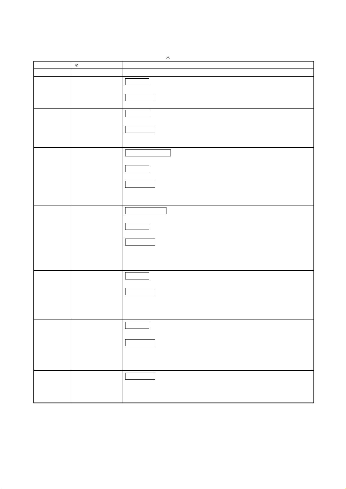
1. OVERVIEW
MELSEC-QnA
The CC-Link system is a system that connects distributed modules such as I/O
1
modules, intelligent function modules, and special function modules using dedicated
cables so that these modules can be controlled by a programmable controller CPU.
This chapter describes outline of the CC-Link.
1
By distributing each module to the equipment device such as the conveyor line and
machine devices, the wiring conservation of the entire system can be accomplished.
2
Simple, high-speed communication can be accomplished with modules that handle
on/off data such as I/O or numeric data.
3
By connecting multiple programmable controller CPUs, a simple distributed system
can be configured.
4
Connections can be made to different types of devices made by partner
manufacturers, giving flexibility to the system.
Master station
Programmable
controller CPU
Remote I/O station
Partner manufacturer's
product
Remote device station
CC - Link system
Remote I/O station
Programmable
controller CPU
Local station
Master station................... Station which controls the remote I/O station, remote device
station, and local stations
Remote I/O station ...........Remote station which handles only on/off data
Remote device station .....Remote station which handles both on/off data and numeric
data
Local station .....................Station which has a CPU and can communicate with the
master station and other local stations
1 - 1
Page 18
1 OVERVIEW
AJ61QBT11 CC-Link System Master/Local
Module
(discontinued on September 2008)
A1SJ61QBT11 CC-Link system
Master/Local Module
MELSEC-QnA
When applying any of the program examples to the actual system, examine the
applicability and confirm that it will not cause system control problems.
After unpacking, please check that the following components are included.
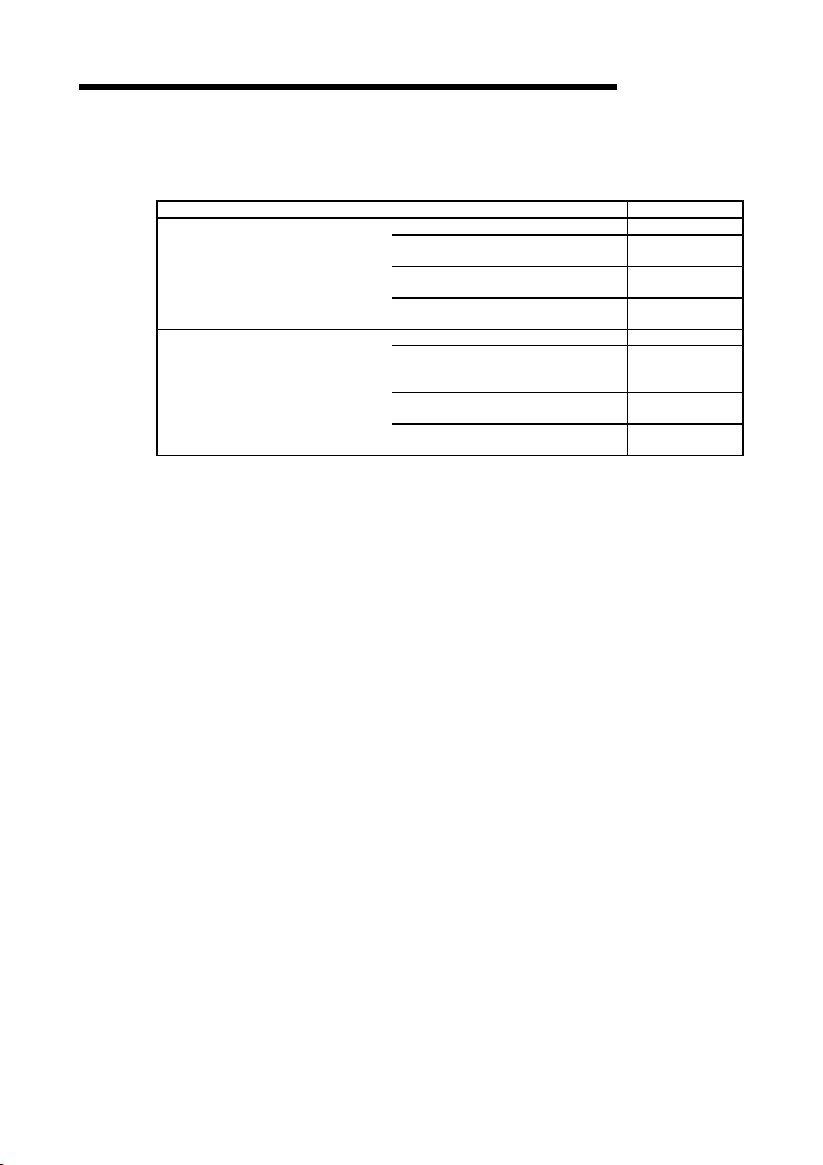
Product name Quantity
AJ61QBT11 1
AJ61QBT11 CC-Link System Master/Local
Module User's Manual (Hardware)
Terminating resistor (110 Ω, 1/2 W)
(All brown)
Terminating resistor (130 Ω, 1/2 W)
(brown, orange, brown)
A1SJ61QBT11 1
A1SJ61QBT11 CC-Link System
Master/Local Module User's Manual
(Hardware)
Terminating resistor (110 Ω, 1/2 W)
(All brown)
Terminating resistor (130 Ω, 1/2 W)
(brown, orange, brown)
1
2
2
1
2
2
1 - 2
Page 19

1 OVERVIEW
1.1 How to Use This Manual
The master/local module has the following functions added from the function version B
or later. The detailed descriptions of the additional functions are provided in Chapter 14
or later.
(1) Scan synchronous function
Link scan can be executed synchronized with the sequence scan.
(2) Standby master function
With this function, the data link can be continuously executed even if an error
occurs in the master station, by automatically switching to the standby master
station.
(3) Dedicated instructions
Transient transmission with the intelligent device and local station is possible.
In addition, read/write of data with handshake to/from the remote device is
feasible.
(4) Temporary error invalid station specification function
By specifying the corresponding remote station as a temporary error invalid
station, an error is not detected even if the module is replaced while in
communication.
(5) Parameter registration function
Parameters such as total number of connected stations and station information
can be set using dedicated instructions.
(6) Automatic refresh function
Data transferred by cyclic transmissions, such as RX and RY, can be refreshed
by the END processing to a desired device, when set up with the dedicated
instruction.
(7) Monitor/diagnosis function
Monitoring and diagnosing can be performed from a peripheral device.
(8) Online test function
Line testing and control of link such as starting up and stopping can be
performed from a peripheral device.
(9) Communication instruction (software version J manufactured in
Jan., 1998 or later)
Data communication with other stations is possible. Data read/write with other
stations is also possible.
(10) Dedicated instruction (software version J manufactured in Jan.,
1998 or later)
Device read/write with respect to the CPU of the specified station are possible.
(11) Remote I/O net mode (software version P manufactured in Sep.,
1998 or later)
When the system is configured only with the master station and the remote I/O
stations, the setting of the network parameters is eliminated and the link
scanning time is shortened by the use of the remote I/O net mode.
1 - 3
MELSEC-QnA
Page 20
1 OVERVIEW
1.2 Characteristics
MELSEC-QnA
The characteristics of the CC-Link are described below:
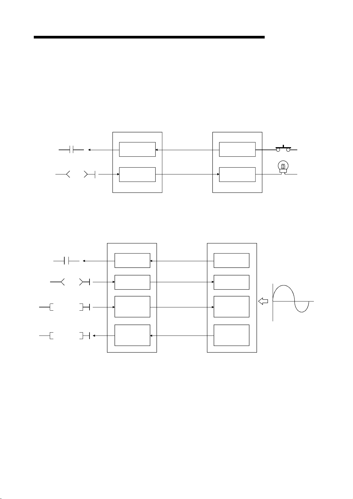
(1) Remote I/O station communication
The communication is performed with only on/off data (remote input RX and
remote output RY).
Master station
Remote I/O station
A/D conversion
completion flag
Offset·gain selection
A/D conversion
enable/disable specification
TO
Remote input
(RX)
Remote output
(RY)
Link scan
Link scan
Input
Output
(2) Remote device station communication
The communication is performed with on/off data (remote input RX and remote
output RY) and numeric data (remote register).
Master station
Remote input
(RX)
Remote output
(RY)
Remote register
(RWw)
Link scan
Link scan
Link scan
Remote device station
Remote input
(RX)
Remote output
(RY)
Remote register
(RWw)
Analog voltage
Digital output value
FROM
Remote register
(RWr)
Link scan
1 - 4
Remote register
(RWr)
Page 21
1 OVERVIEW
Master station
MELSEC-QnA
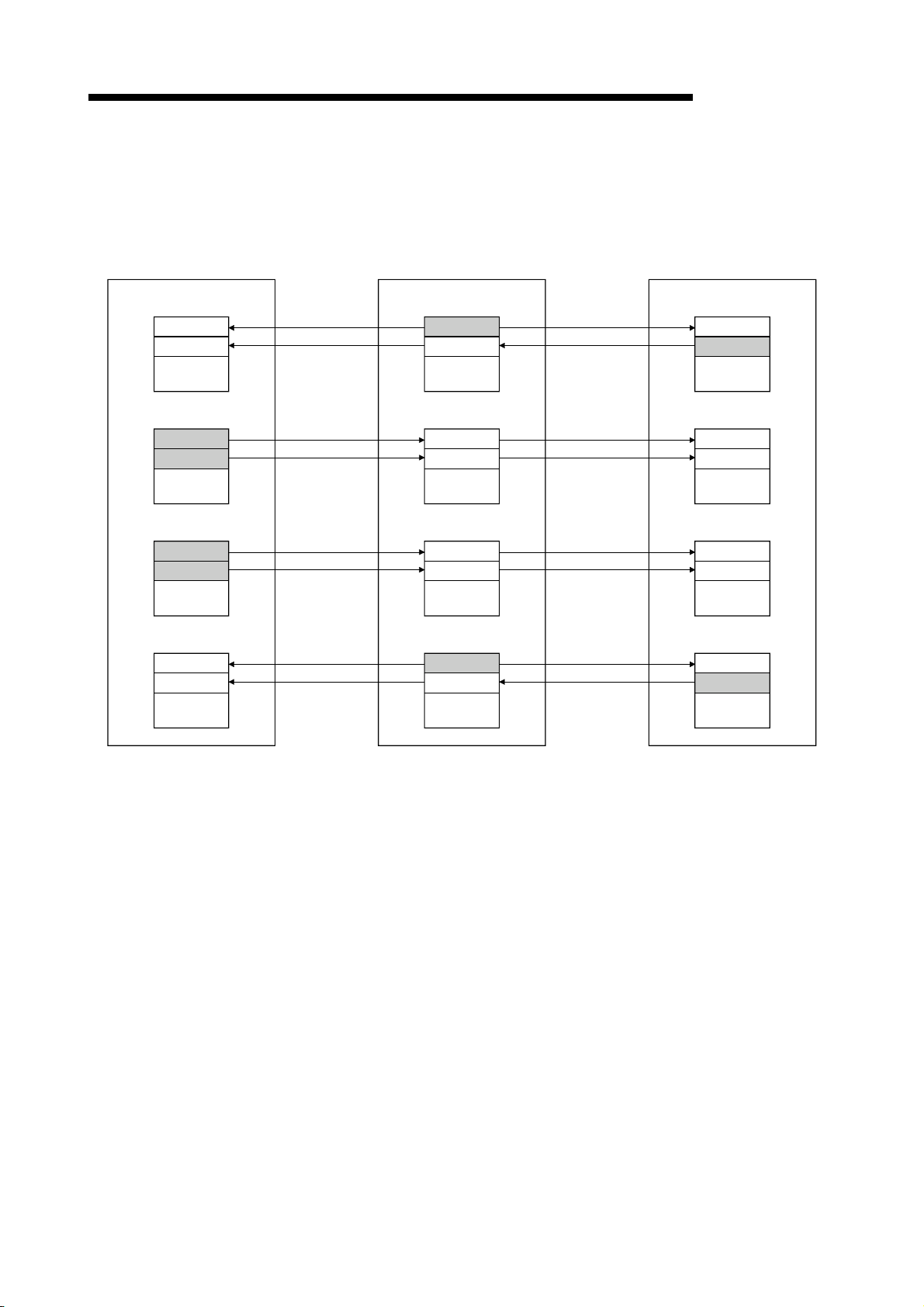
(3) Local station communication
The data communication between programmable controller CPUs can be
performed in N:N relationship with bit data (remote input RX and remote output
RY) and word data (remote register)
Local station
Local station
Remote input (RX)
Remote output (RY)
Remote register (RWw)
Remote register (RWr)
Link scan
Link scan
Link scan
Link scan
Remote output (RY)
Link scan
Remote input (RX)
Link scan
Remote register (RWr)
Link scan
Remote register (RWw)
Link scan
Remote output (RY)
Remote input (RX)
Remote register (RWr)
Remote register (RWw)
(4) Establishing high-speed transmission
When the transmission speed of 10Mbps is set, the link scan time
(communication time with the master station and remote station/local station) is
still at high speed, even when the maximum 64 stations are connected.
• Remote I/O (RX, RY) 2048 points ..................................................... 4 ms
• Remote I/O (RX, RY) 2048 points
+ remote register (RWw, RWr) 512 points ................ 7 ms
(5) System configurations are possible, according to requirements.
(a) Transmission distance
The total extended distance depends on the transmission speed, but
connections can be made between 100 m (at 10 Mbps) and 1.2 km (at 156
kbps).
(b) Number of connected stations
A maximum of 64 stations, including remote I/O stations, remote device
stations, and local stations can be connected to one master station.
Up to 64 remote I/O stations, 42 remote device stations, and 26 local
stations can be connected. (Refer to Section 2.1.)
1 - 5
Page 22
1 OVERVIEW
MELSEC-QnA
(6) Link points
2048 points of remote input (RX), 2048 points of remote output (RY), and 512
points of remote register (RW) can be used for communication in one system.
For one remote station or local station, 32 points of remote input (RX), 32 points
of remote output (RY), and 8 points of remote register (RW) (RWw: 4 points,
RWr: 4 points) can be handled.
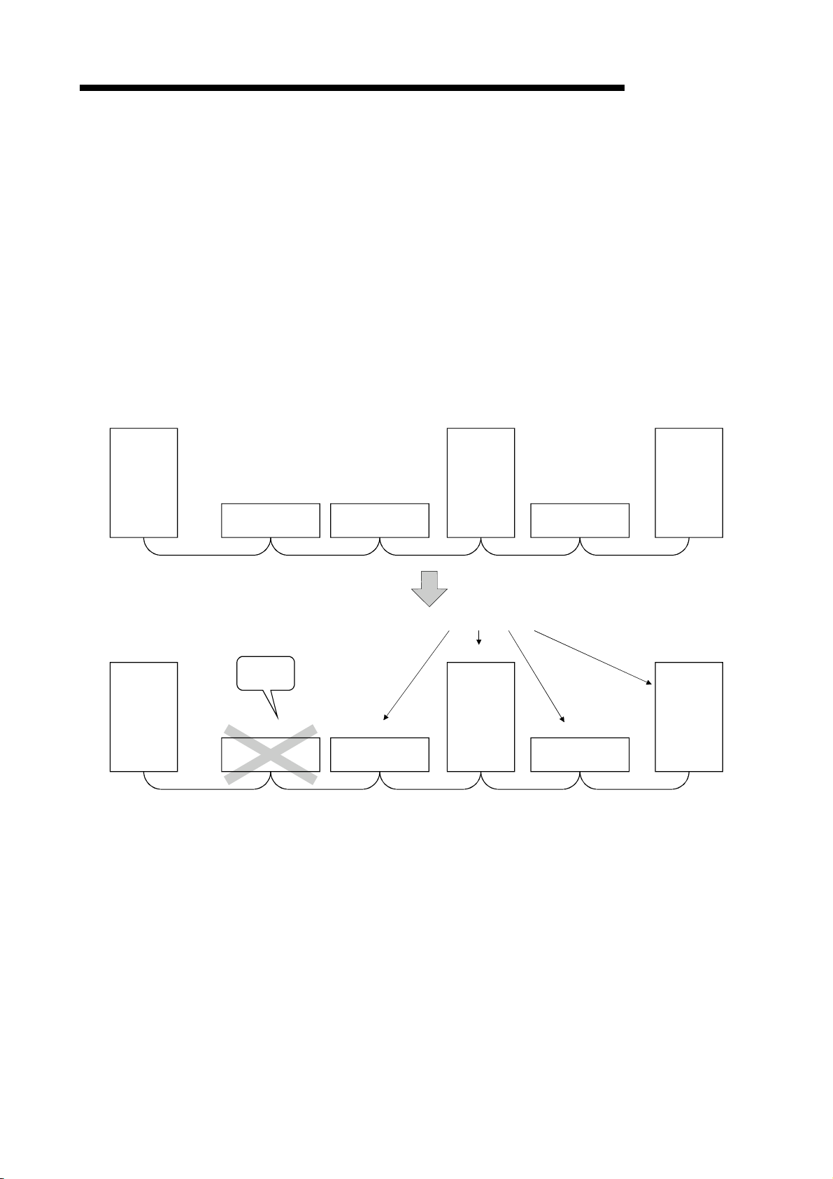
(7) System down prevention (Station cutoff function)
Because the system employs the bus method, even if there is a remote station or
local station which goes down due to power off, etc., it won't affect the
communication with other functioning remote/local stations.
Also, for the module using with the 2-piece terminal block, the module can be
replaced during data link.
Station No.4
Station No.7
Master
station
Master
station
Station No.1
Remote station
(occupies 2 stations)
Faulty
station
Station No.1
Remote station
(occupies 2 stations)
Station No.3
Remote station
(occupies 1 station)
Station No.3
Remote station
(occupies 1 station)
Local station
(occupies 1
station)
Data link continues
Station No.4
Local station
(occupies 1
station)
Station No.5
Remote station
(occupies 2 stations)
Station No.5
Remote station
(occupies 2 stations)
Local station
(occupies 4
stations)
Station No.7
Local station
(occupies 4
stations)
1 - 6
Page 23
1 OVERVIEW
MELSEC-QnA
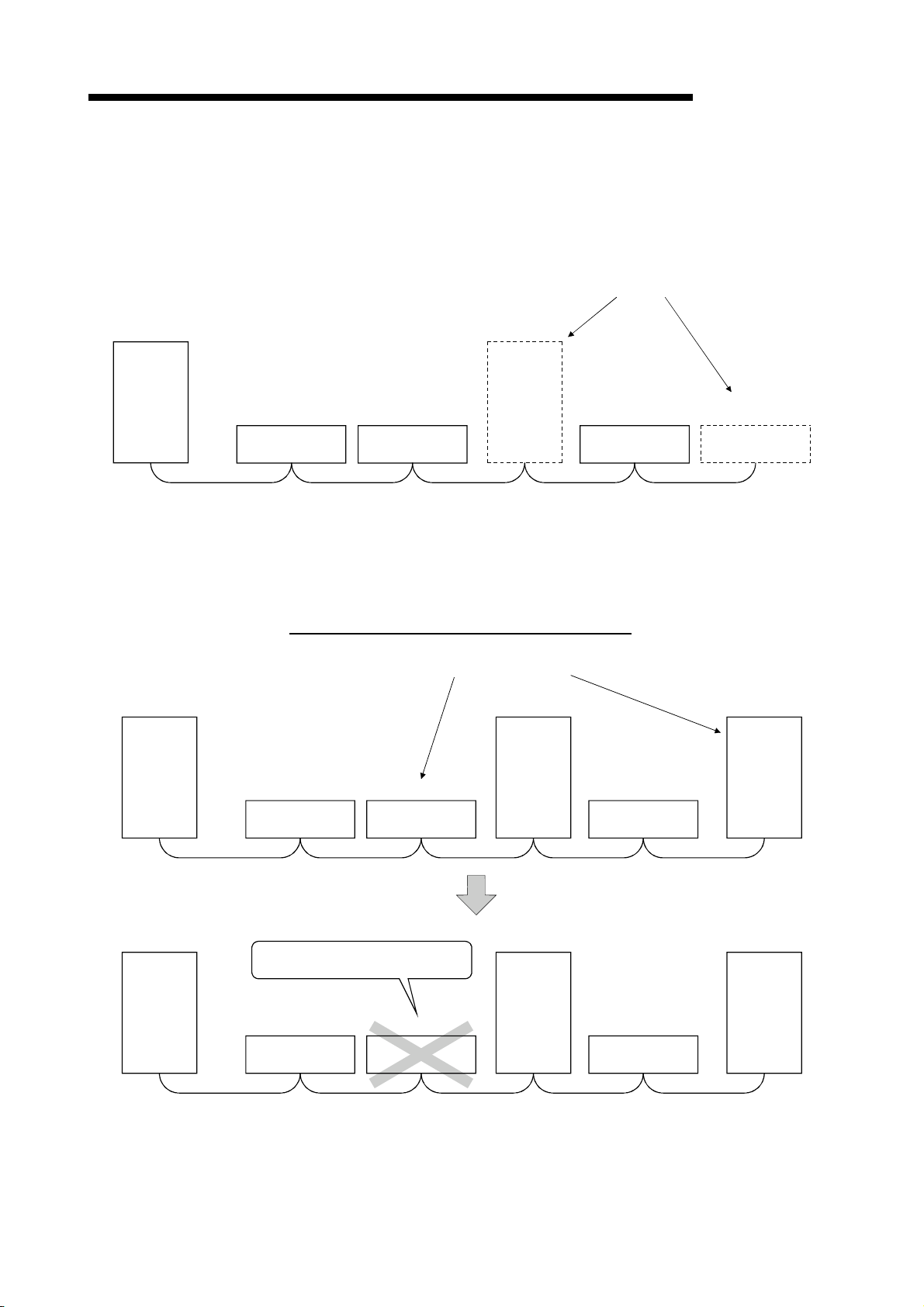
(8) Reserved station function
By setting the station which is not actually connected (station planned for
connection in the future) as a reserved station, the station will not be handled as
a faulty station.
Station planned for
connection in the future
(Reserved station)
Station No.4
Master
station
Station No.1
Remote station
(occupies 2 stations)
Station No.3
Remote station
(occupies 1 station)
Local station
(occupies 4
stations)
Station No.8
Remote station
(occupies 1 station)
(Reserved station)
Station No.9
Remote station
(occupies 1 station)
(9) Error invalid station function
A station that cannot perform data links because the power is turned off, etc., can
be handled as other than a "data-link faulty station" on the master station and the
local station.
Be careful, however, for errors will not be detected.
Stations to be set as error invalid stations
Station No.4
Master
station
Station No.1
Remote station
(occupies 2 stations)
Station No.3
Remote station
(occupies 1 station)
Local station
(occupies 1
station)
Station No.5
Remote station
(occupies 2 stations)
Station No.7
Local station
(occupies 4
stations)
Master
station
Does not result as a data-link faulty
station.
Station No.1
Remote station
(occupies 2 stations)
Station No.3
Remote station
(occupies 1 station)
1 - 7
Station No.4
Local station
(occupies 1
station)
Station No.5
Remote station
(occupies 2 stations)
Station No.7
Local station
(occupies 4
stations)
Page 24
1 OVERVIEW
Programmable controller CPU Master station
MELSEC-QnA
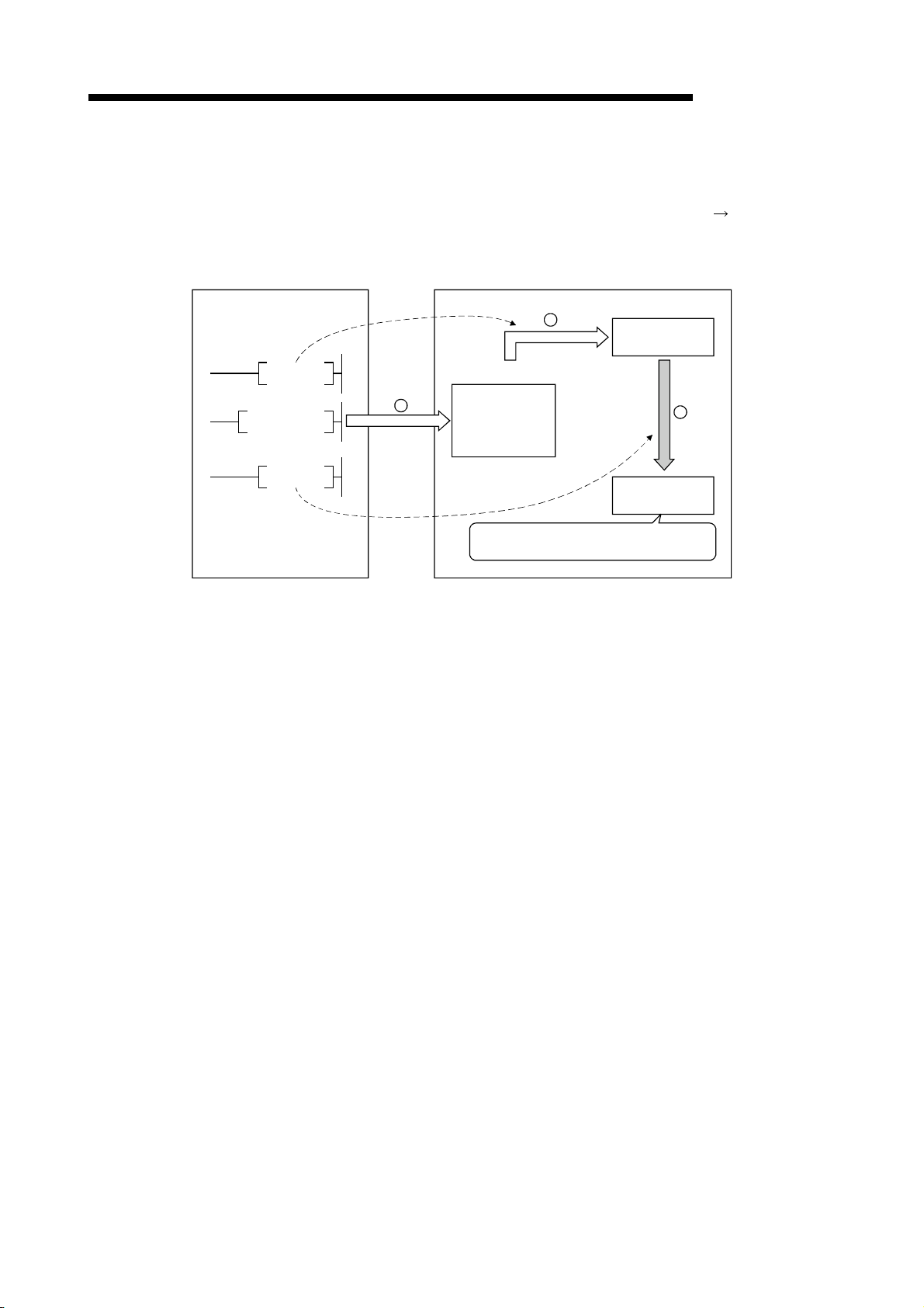
(10) Parameter registration to the E2PROM
By registering the parameters to the E2PROM, the parameter settings do not
have to be performed at each master station startup (power off
Because this is the E
is turned off.
2
PROM, parameters are stored even if the module's power
on).
2
SET YnA
1
TO
SET Yn8
Buffer memory
Parameter
information area
The data link is executed using the parameters
registered in the internal memory.
2
EPROM
3
Internal memory
(11) Data-link status setting for when a master station programmable
controller CPU error occurs
The data-link status can be set (stop/continue) to either stop or continue for when
a "operation stop error" occurs at the master station's programmable controller
CPU, such as SP. UNIT ERROR.
The data link between local stations can be continued.
"Operation continue errors" such as a BATTERY ERROR continue the data link
regardless of the setting.
(12) Input data from data-link faulty station status setting
The data input (received) from the data-link faulty station can be cleared or kept
(status right before an error is caused).
(13) Module reset function from the sequence program
When the switch setting is changed or an error occurs in the module, the module
can be reset from the sequence program without resetting the programmable
controller CPU.
(This excludes when the module has a module faulty (Xn0 is on).)
(14) RAS function
(a) Automatic return function
When a station is disconnected from the link due to power off, etc., and
returns to the normal status, the station can join the data link again
automatically.
(b) Link status check
Using the link special relay (SB) and link special register (SW) in the buffer
memory, the current data-link status can be checked.
(c) Diagnosis function
Using the switch setting, the hardware and cable conditions can be
checked.
1 - 8
Page 25
1 OVERVIEW
1.3 Communication Overview
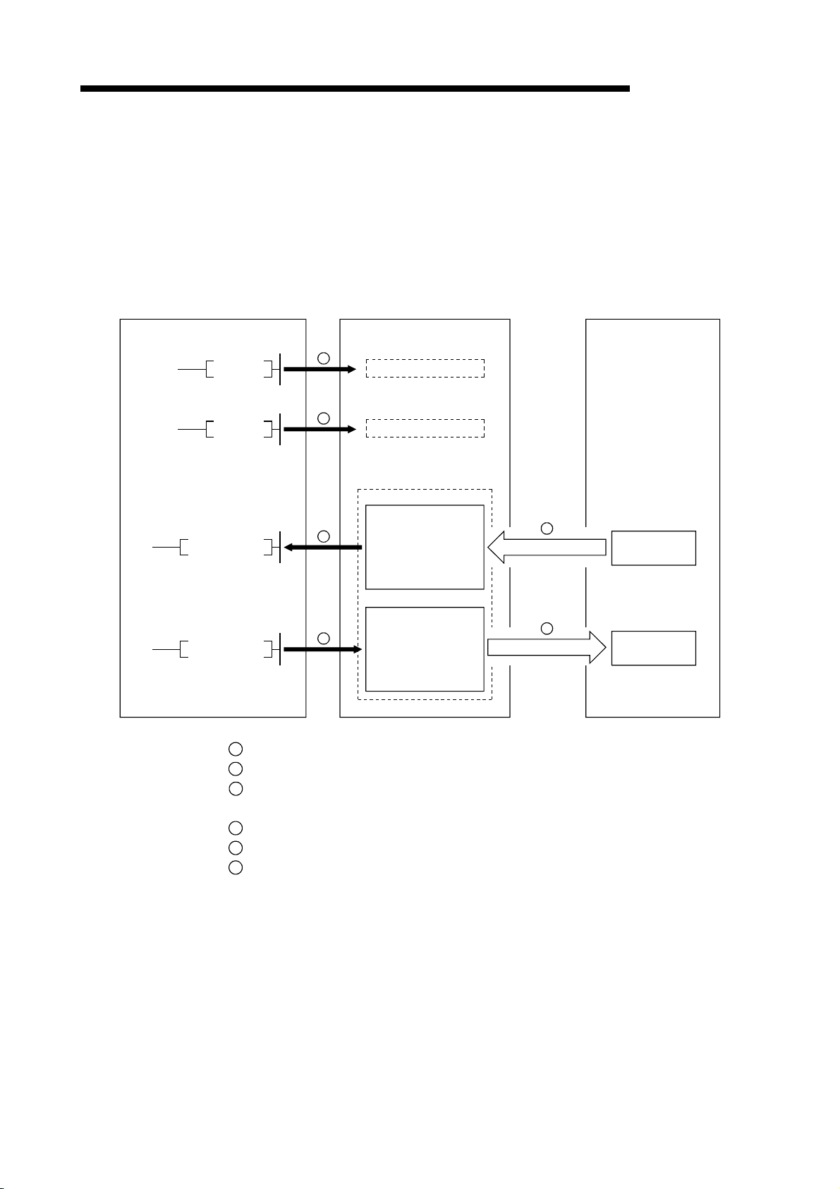
1.3.1 Communication between the master station and remote I/O station
The overview of the communication between the master station and remote I/O station
is described below.
Refer to Section 4.2 for details.
Programmable controller CPU
Master station
MELSEC-QnA
Remote I/O station
FROM
TO
SET Yn0
SET Yn6
1
2
4
5
Refresh instruction
Data link startup
Buffer memory
Remote input
(RX)
Remote output
(RY)
3
Link scan
6
Link scan
Input
Output
1
Turn on the refresh instruction.
2
Startup the data link.
3
By the link scan, the remote I/O station's input information is stored in the master
station's remote input (RX).
4
By the FROM instruction, read from the remote input (RX).
5
By the TO instruction, write the on/off data to the remote output (RY).
6
By the link scan, the remote I/O station's output is turned on/off.
1 - 9
Page 26
1 OVERVIEW
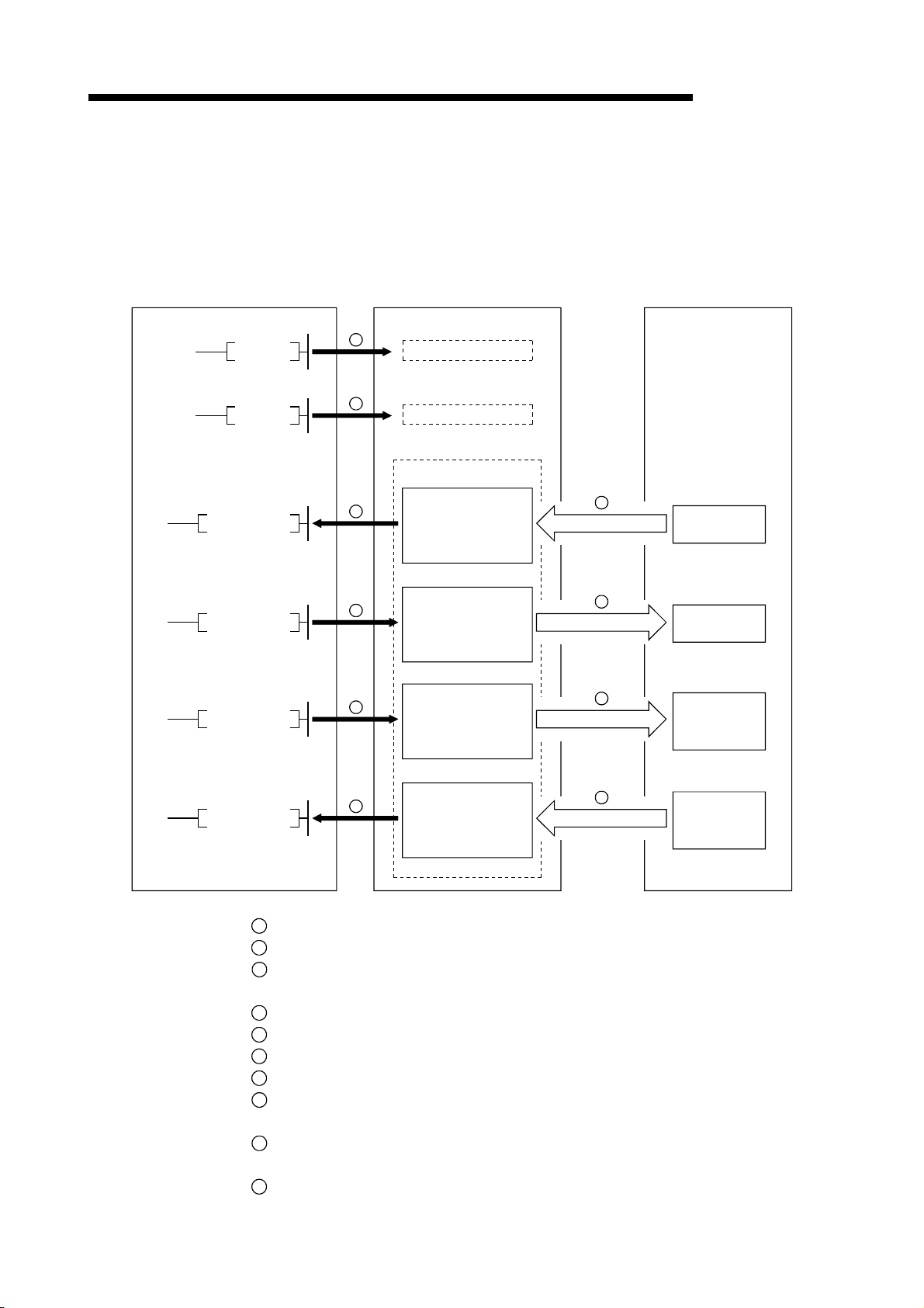
1.3.2 Communication between the master station and remote device station
The overview of the communication between the master station and remote device
station is described below.
Refer to Section 4.3 for details.
Programmable controller CPU
Master station
Remote device station
MELSEC-QnA
FROM
TO
TO
SET Yn0
SET Yn6
1
2
4
5
7
Refresh instruction
Data-link startup
Buffer memory
Remote input
(RX)
Remote output
(RY)
Remote register
(RWw)
3
Link scan
6
Link scan
8
Link scan
Remote input
(RX)
Remote output
(RY)
Remote register
(RWw)
9
Link scan
Remote register
(RWr)
FROM
10
Remote register
(RWr)
1
Turn on the refresh instruction.
2
Startup the data link.
3
By the link scan, the remote device station's remote input (RX) is stored in the
master station's remote input (RX).
4
By the FROM instruction, read data from the remote input (RX).
5
By the TO instruction, write data to the remote output (RY).
6
By the link scan, the remote device station's remote output (RY) is turned on/off.
7
By the TO instruction, write data to the remote register (RWw).
8
By the link scan, the data is sent to the remote device station's remote register
(RWw).
9
By the link scan, the remote device station's remote register (RWr) is sent to the
master station's remote register (RWr).
10
By the TO instruction, read data from the remote register (RWr).
1 - 10
Page 27
1 OVERVIEW
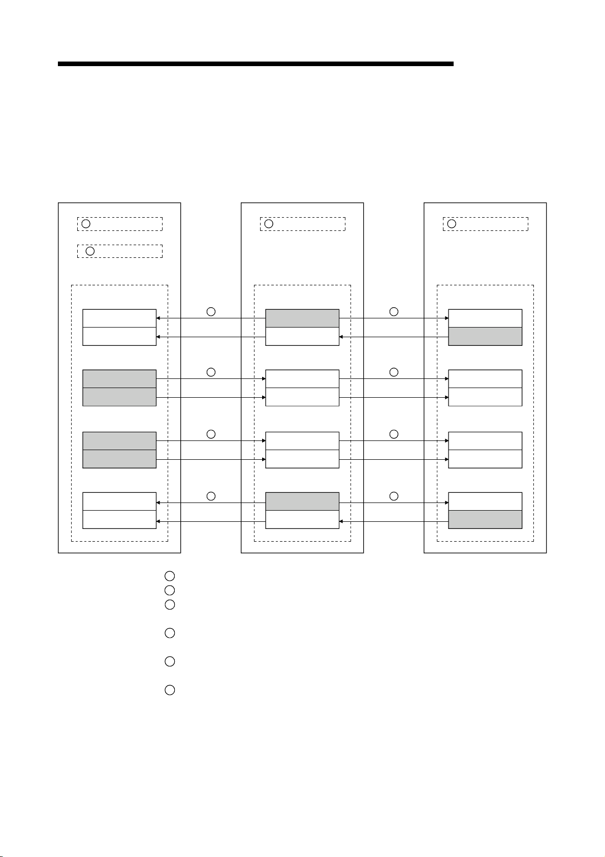
1.3.3 Communication between the master station and local station
The overview of the communication between the master station and local station is
described below.
Refer to Section 4.4 for details.
Master station
Local station
MELSEC-QnA
Local station
1
Refresh instruction
2
Data link startup
Buffer memory
Remote input (RX)
Remote output (RY)
Remote register (RWw)
Remote register (RWr)
3
Link scan
4
Link scan
5
Link scan
6
Link scan
1
Refresh instruction
Buffer memory
Remote output (RY)
Remote input (RX)
Remote register (RWr)
Remote register (RWw)
3
Link scan
4
Link scan
5
Link scan
6
Link scan
1
Refresh instruction
Buffer memory
Remote output (RY)
Remote input (RX)
Remote register (RWr)
Remote register (RWw)
1
Turn on the refresh instruction.
2
Startup the data link.
3
By the link scan, the data in the local station's remote output (RY) is sent to the
master station's remote input (RX) and other local stations' remote output (RY).
4
By the link scan, the data in the master station's remote output (RY) is sent to all
local station's remote input (RY).
5
By the link scan, the data in the master station's remote register (RWw) is sent to all
local stations' remote register (RWr).
6
By the link scan, the data in the local station's remote register (RWw) is sent to the
master station's remote register (RWr) and other local stations' remote register
(RWw).
1 - 11
Page 28
1 OVERVIEW
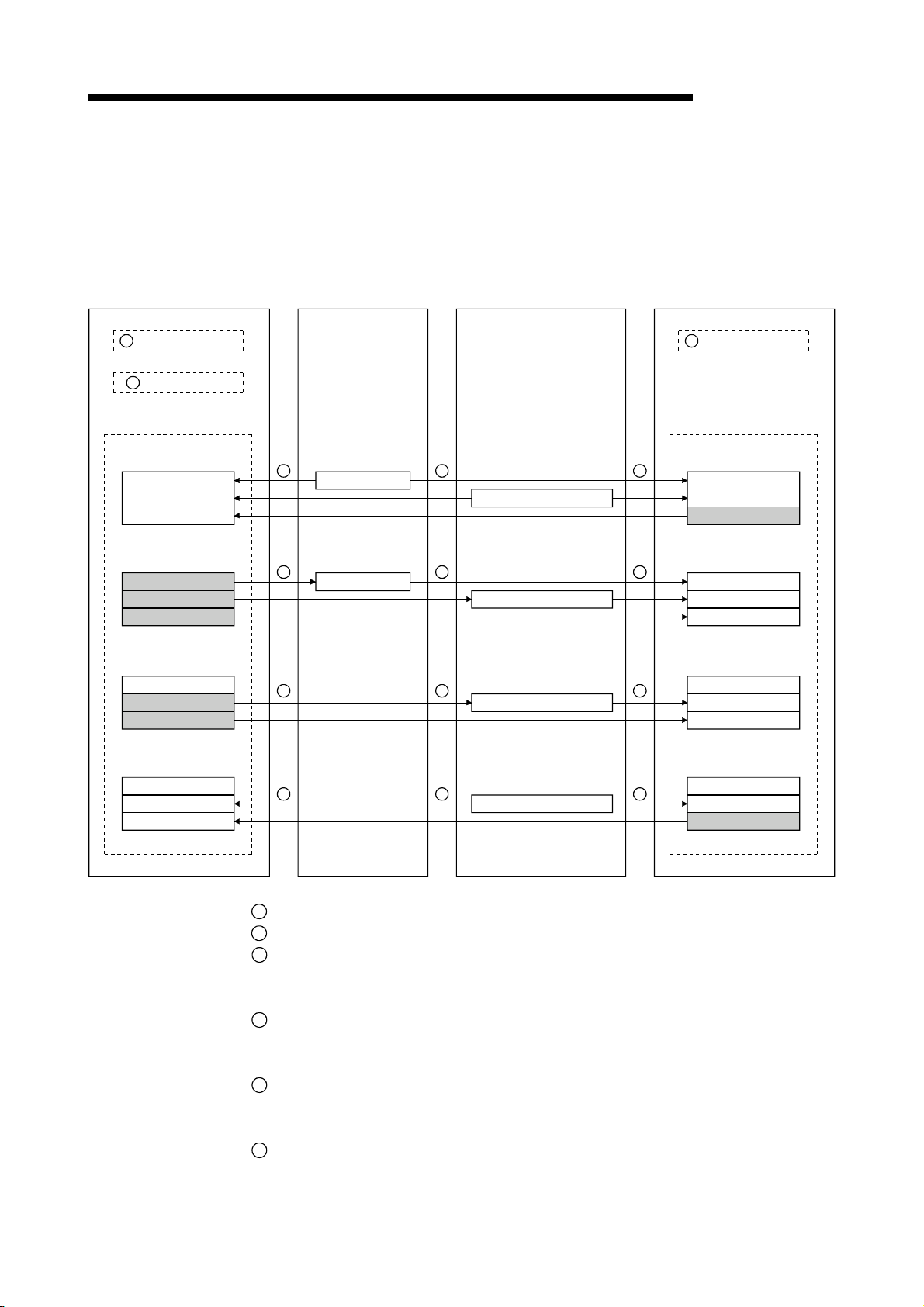
1.3.4 Compound system communication
The overview of compound system communication with remote I/O stations, remote
device stations, and local stations is described below.
Refer to Section 4.5 for details.
Master station
Remote I/O station
Remote device station
MELSEC-QnA
Local station
1
Refresh instruction
2
Data link startup
Buffer memory
Remote input (RX)
Remote output (RY)
Remote register (RWw)
Remote register (RWr)
3 3 3
4 4 4
5 5 5
6 6 6
Input
Remote input (RX)
Output
Remote output (RY)
Remote register (RWw)
Remote register (RWr)
1
Refresh instruction
Buffer memory
Remote output (RY)
Remote input (RX)
Remote register (RWr)
Remote register (RWw)
1
Turn on the refresh instruction.
2
Startup the data link.
3
By the link scan, data in the remote I/O station's and remote device station's remote
input (RX) and local station's remote output (RY) is sent to the master station's
remote input (RX) and local station's remote output (RY).
4
By the link scan, data in the master station's remote output (RY) is sent to the
remote I/O station's and remote device station's remote output (RY) and local
station's remote input (RX).
5
By the link scan, data in the master station's remote register (RWw) is sent to the
remote device station's remote register (RWw) and local station's remote register
(RWr).
6
By the link scan, data in the remote device station's remote register (RWr) and local
station's remote register (RWw) is sent to the master station's remote register (RWr)
and local station's remote register (RWw).
1 - 12
Page 29
1 OVERVIEW
MELSEC-QnA
1.4 Number of Occupied Stations and Station Number, Number of Modules and Number of Stations
The relationship between number of occupied station and station number, and
between number of modules and number of stations is described below.
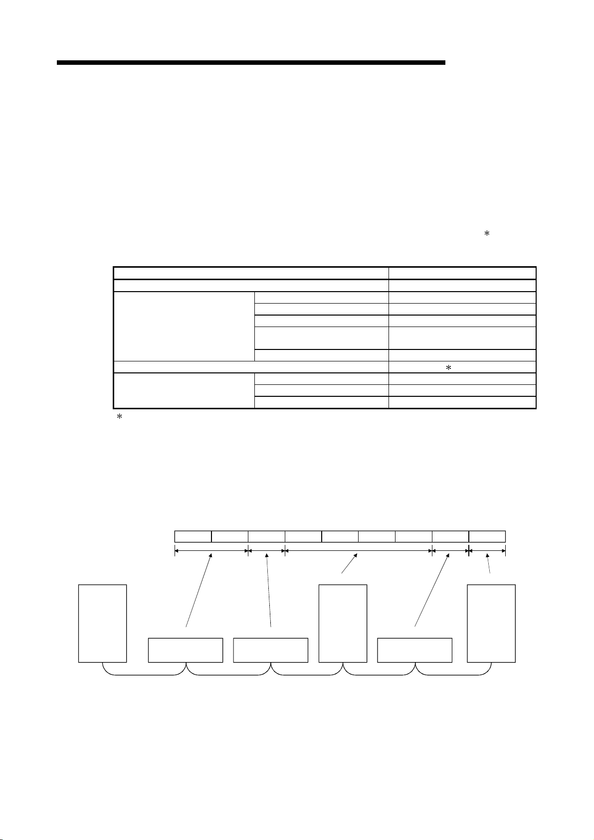
(1) Number of occupied stations
The number of occupied stations is fixed for each module (remote I/O station,
remote device station, and local station).
However, the number of occupied stations can be set (1 to 4 stations
) for local
stations.
Module Number of occupied stations
Remote I/O station (16 points and 32 points module) 1 station
AJ65BT-64AD 2 stations
AJ65BT-64DAV 2 stations
Remote device station
Local station 1 to 4 stations (changed by switch)
Intelligent device station
The AJ61QBT11 of hardware version F or later and the A1SJ61QBT11 of hardware version G or later are
compatible with this setting. For other than the above, the setting is 1 or 4 stations only.
AJ65BT-64DAI 2 stations
AJ65BT-D62
AJ65BT-D62D (S1)
A852GOT 2 or 4 stations
AJ65BT-R2(N) 1 station
AJ65BT-G4 1 station
AJ65BT-D75P2-S3 4 stations
4 stations
(2) Station number
When the number of occupied station for all connected stations is set to "1
station," the station number is set continuously from 1 (e.g. 1, 2, 3,... ).
However, when a station which occupies more than 2 stations is connected, the
setting must be performed considering the number of occupied stations.
Station No.5 Station No.6Station No.7 Station No.8 Station No.9Station No.4Station No.3Station No.2Station No.1
Master
station
Station No.1
Remote station
(occupies 2 stations)
Station No.3
Remote station
(occupies 1 station)
Station No.4
Local station
(occupies 4
stations)
Station No.8
Remote station
(occupies 1 station)
Station No.9
Local station
(occupies 1
station)
(3) Number of modules and number of stations
Number of modules is a physical module count.
Number of stations is a number of occupied stations for each module as stated in
(1).
In the system configuration example in (2), the number of modules is 5 and
number of stations is 9.
1 - 13
Page 30

1 OVERVIEW
MELSEC-QnA
1.5 Generic Terms and Abbreviations
Generic terms and abbreviations used in this manual are shown below.
Generic Term/Abbreviation
AJ61QBT11 Abbreviation for the AJ61QBT11 CC-Link System Master/Local Module.
A1SJ61QBT11 Abbreviation for the A1SJ61QBT11 CC-Link System Master/Local Module.
Master station
Local station
Remote I/O station
Remote device station
Remote station Generic term for remote I/O station and remote device station. (Controlled by a master station)
Intelligent device station Station that can perform transient transmission, such as the AJ65BT-R2(N) (Including local station).
Standby master station
Slave station
Master/local module Generic term for the AJ61QBT11, and A1SJ61QBT11.
Master module Generic term for the AJ61QBT11, and A1SJ61QBT11 when they are used as master station.
Local module Generic term for the AJ61QBT11, and A1SJ61QBT11 when they are used as local station.
Remote module
AJ65BT-R2(N) Generic term for AJ65BT-R2 and AJ65BT-R2N.
Intelligent device module Module that can perform transient transmission, such as AJ65BT-R2(N) (including local module).
Remote I/O net mode Dedicated mode for sending and receiving data to and from the remote I/O station at high speed.
Remote net mode
Cycric transmission
Transient transmission
AnSCPU
AnCPU Generic term for the A1CPU, A2CPU, A2CPUS1, and A3CPU.
AnNCPU Generic term for the A1NCPU, A2NCPU, A2NCPUS1, and A3NCPU.
AnACPU Generic term for the A2ACPU, A2ACPUS1, and A3ACPU.
A2USCPU Generic term for the A2USCPU and A2USCPUS1.
AnUCPU Generic term for the A2UCPU, A2UCPUS1, A3UPU, and A4UCPU.
Q2ASCPU Generic term for the Q2ASCPU, Q2ASCPUS1, Q2ASHCPU, and Q2ASHCPUS1.
QnACPU Generic term for the Q2ACPU, Q2ACPUS1, Q3ACPU, and Q4ACPU.
SB
SW
RX
RY
Station that controls the data link system.
One master station is required for each system.
Station having a programmable controller CPU and the ability to communicate with the master and other
local stations.
Remote station that handles bit unit data only. (Performs input and output with external devices.)
(AJ65BTB1-16D, AJ65SBTB1-16D)
Remote station that handles bit unit and word unit data only. (Performs input and output with external
devices, and analog data conversion.)
(AJ65BT-64AD, AJ65BT-64DAV, AJ65BT-64DAI)
Backup station for data link control when the link to the master station is disconnected due to a
programmable controller CPU or power supply problem.
Generic term for the remote I/O station, remote device station, local station, intelligent device station and
standby master station.
Generic term for the AJ65BTB1-16D, AJ65SBTB1-16D, AJ65BT-64AD, AJ65BT-64DAV, AJ65BT-64DAI,
and A852GOT.
Mode that can communicate with all stations used for CC-Link (remote I/O station, remote device station,
local station, intelligent device station, and standby master station)
Transmission method by which to periodically communicate the contents of remote I/O, and remote
registers.
Transmission method with which the counterpart is specified and 1:1 communication is used at an
arbitrary timing.
Generic term for the A1SCPU, A1SCPU-S1, A1SJCPU, A1SJCPU-S3, A2SCPU, A2SCPU-S1, and
A1SCPUC24-R2.
Link special relay (for CC-Link)
Bit unit information that indicates the module operating status and data link status of the master
station/local station.
Link special register (for CC-Link)
16-bit unit information that indicates the module operating status and data link status of the master
station/local station.
Remote input (for CC-Link)
Information entered in bit units from the slave stations to the master station.
Remote output (for CC-Link)
Information output in bit units from the master station to the slave station
Description
1 - 14
Page 31

1 OVERVIEW
Generic Term/Abbreviation
RWw
RWr
Description
Remote register (Write area for CC-Link)
Information output in 16-bit units from the master station to the slave station.
Remote register (Read area for CC-Link)
Information entered in 16-bit units from the slave station to the master station.
MELSEC-QnA
1 - 15
Page 32

2 SYSTEM CONFIGURATION
2. SYSTEM CONFIGURATION
MELSEC-QnA
2.1 Total Configuration
2
Master station
The system configuration for the CC-Link is described in this chapter.
A total of 64 remote I/O stations, remote device stations, or local stations can be
connected for one master station.
However, the following conditions must be satisfied:
(1) {(1×a)+(2×b)+(3×c)+(4×d)} 64
a : Number of modules occupying 1 station c : Number of modules occupying 3 stations
b : Number of modules occupying 2 stations d : Number of modules occupying 4 stations
(2) {(16×A)+(54×B)+(88×C)} 2304
A : Number of remote I/O stations 64
B : Number of remote device stations 42
C : Number of local stations, standby master stations, intelligent device stations 26
Maximum 26
Local station Local station
A1SJ61QBT11
AJ61QBT11
A1SJ61BT11
AJ61BT11
A1SJ61QBT11
AJ61QBT11
Terminating resistor
(mandatory)
Maximum 42Maximum 26
CC-Link dedicated cable
Maximum 64
Remote I/O stationRemote device stationIntelligent device station
RS-232C
Interface module
AJ65BT-R2N
Analog-digital
conversion module
AJ65BT-64AD
Remote I/O module
AJ65BTB -
AJ65BTC -
Terminating resistor
(mandatory)
CC-Link dedicated cable
Total 64
2 - 1
Page 33

2 SYSTEM CONFIGURATION
2.2 Applicable System
The applicable CPU modules and the precautions for system configuration are
described below.
2.2.1 Applicable CPU and number of modules that can be installed
The applicable programmable controller CPU, data link system/network system, and
the number of modules that can be installed are shown in Table 2.1.
However, intelligent mode cannot be used for future plan.
Programmable
controller CPU
Data link and
network
Table 2.1 Number of modules that can be installed
Installation area A1SJ61QBT11 AJ61QBT11
A0J2CPU
A0J2HCPU
A1SCPU (S1)
A1SHCPU
A1SJCPU (S3)
A1SJHCPU (S8)
A1SCPUC24-R2
A2SCPU (S1)
A2SHCPU (S1)
A2ASCPU (S1/S30)
A2USHCPU-S1
Q2ASCPU (S1)
Q2ASHCPU (S1)
A1CPU
A2CPU (S1)
A3CPU
A1NCPU
A2NCPU (S1)
A3NCPU
A3MCPU
A3HCPU
A2ACPU (S1)
A3ACPU
A2UCPU (S1)
A3UCPU
A4UCPU
Q2ACPU (S1)
Q3ACPU
Q4ACPU
Q4ARCPU
MELSECNET remote I/O station Unusable Unusable
MELSECNET/B remote I/O station Unusable Unusable
AJ72LP25
AJ72LP15
MELSECNET/10
remote I/O station
AJ72QLP25
AJ72QBR15
A1SJ72QLP25
A1SJ72QBR15
Unusable Unusable
No restrictions No restrictions
Unusable
Unusable Unusable
Unusable No restrictions
No restrictions No restrictions
MELSEC-QnA
Unusable
No restrictions
2 - 2
Page 34

2 SYSTEM CONFIGURATION
2.2.2 Precautions when configuring a system
Design the system with the following considerations to prevent mis-input from the
remote I/O module:
(1) During power on and power off
Start the data link after turning on the power for the remote I/O module.
Turn off power for the remote I/O module after stopping the data link.
During
Master module
(Data-link status)
Remote I/O module
(Power supply status)
operation
During stop
(2) During momentary power failure of the remote I/O module
When momentary power failure occurs with the power (24VDC) supplied to the
remote I/O module, mis-input may occur.
(a) Cause for mis-input due to a momentary power failure
The remote I/O module hardware uses the power after internally converting
the module power (24VDC) in to 5VDC.
When momentary power failure occurs with the remote I/O module, the
following condition occurs:
(Time for the 5VDC in the internal remote I/O module to turn off) > (input
module on
Therefore, mis-input is caused when a refresh is performed within the time
indicated by
Remote I/O module
(Module power supply
and input external-power
supply)
off response time)
1
) in the diagram below.
ON
OFF
MELSEC-QnA
Data link start Data link stop
1
Remote I/O module
(Internal 5VDC)
Input (Xn)
Because the input external-power supply is turned off,
the input (Xn) turns off after the response time of input
module is turned off.
2 - 3
Page 35

2 SYSTEM CONFIGURATION
(b) Countermeasure for mis-input
Wire the power supply cable for the power supply module, stabilized power,
and input/external-supply power of the AC input from the same power
source.
Programmable
controller CPU
MELSEC-QnA
For DC input
For AC input
Power supply module
Stabilized
power supply
Programmable
controller CPU
Power supply module
Stabilized
power supply
24VDC
24VDC
Master module
Module power supply
Master module
Module power supply
Remote I/O module
Input
external-supply
power
Remote I/O module
Input
external-supply
power
REMARK
When supplying power from one power source to multiple remote I/O modules, select the cable
and perform the wiring with considerations to the voltage decline from the cables.
Connections can be established if the remote I/O module's receiving port voltage is within the
specification range of the used remote I/O module.
Stabilized
power supply
Remote module
2 - 4
Remote module
Page 36
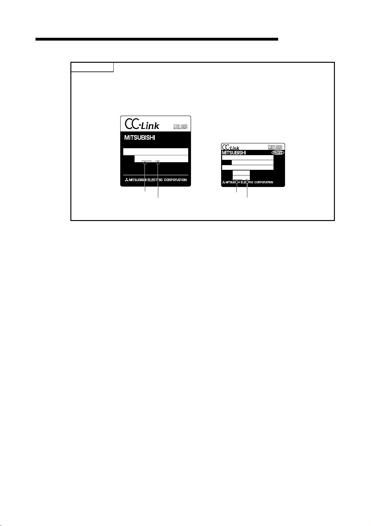
2 SYSTEM CONFIGURATION
POINT
To utilize the functions described in Chapter 14 or later, use a module with "9707B*" or later is
shown as a DATE code on the rating plate.
* "9707B" indicates that the module was manufactured in July 1997 and its function version is
B.
PROGRAMMABLE CONTROLLER
DATE
MADE IN JAPAN
Manufactured
date
(3) Access to station No.64
(a) To a local station of No. 64, other station access from GX Developer or
GOT is not allowed.
If the station No. is changed to other than 64, other station access is
executable.
(b) The CC-Link board is not allowed to access a local station or intelligent
device station whose station No. is 64.
If the station No. is changed to other than 64, other station access is
executable.
(4) Precautions for use on remote I/O stations
Transient transmissions using dedicated instructions are not allowed to local
stations and intelligent device stations.
0512 B
Function
version
BD992C103H06
MODEL
POWER
DATE
0512 B
MADE IN JAPAN BD992C154H06
Manufactured
date
Function
version
MELSEC-QnA
2 - 5
Page 37
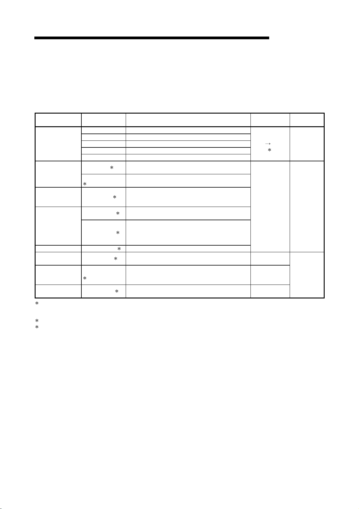
2 SYSTEM CONFIGURATION
MELSEC-QnA
2.2.3 List of system equipment restricted by master/local module versions
Table 2.2 lists the CC-Link system equipment restricted by the function, hardware and
software versions of the master/local modules.
Product name Model Description
A1SJ61BT11 Master/local module for AnS/A2US series
AJ61BT11 Master/local module for A series
Master/local module
High-speed counter
module
Thermocouple
temperature input
module
Platinum
temperature
measuring resistor
Pt100
temperature input
module
ID interface module AJ65BT-D32ID2 2 Number of readers/writers that can be connected is 2
RS-232C interface
module
Positioning module
Peripheral device
connection module
1 Supported by the hardware version F and later of the AJ61BT11 and AJ61QBT11, the hardware version G and later of the
A1SJ61BT11 and A1SJ61QBT11, and the function version B and later of the QJ61BT11.
For other than the above, the setting is one station or four stations only.
2: Can be used with function version B or later.
3: Can be used with software version J (manufactured in Jan., 1998) or later.
A1SJ61QBT11 Master/local module for Q2AS series
AJ61QBT11 Master/local module for QnA series
QJ61BT11 Master/local module for Q series
AJ65BT-D62 2
AJ65BT-D62D(S1)
2
AJ65BT-68TD
AJ65BT-64RD3 2
AJ65BT-64RD4
AJ65BT-R2(N)
AJ65BT-D75P2-S3
2
AJ65BT-G4-S3
2
2
3
For a list of products by partner manufacturers, refer to the following CC-Link Partner
Association website.
http://www.cc-link.org/
Table 2.2 System equipment list
24 bit binary, 5/12/24VDC input type,
200kPPS, 2 channels
24 bit binary, differential input type,
400kPPS, 2 channels
For connecting thermocouple
Temperature input 8 channels
For connecting Pt 100 (3 wire type)
Temperature input 4 channels
For connecting Pt 100 (4 wire type)
2
Temperature input 4 channels
Computer link function
RS-232C, 1 channel
For positioning control, Pulse chain output 2 axes
(independent, simultaneous 2 axial, 2 axial linear
interpolation and 2 axial circular interpolation)
For peripheral device connection
RS-422, 1 channel
Number of
occupied stations
When local
station 1 to 4
stations
1
4 stations
1 station
4 stations
1 station
Station type
Master or local
station
Remote device
staion
Intelligent
device station
2 - 6
Page 38

2 SYSTEM CONFIGURATION
2.2.4 About Ver. 1.10
The module of which the station to station cable length is uniformly 20cm or more by
improving the conventional limit of the station to station cable length is defined as Ver.
1.10.
The conventional modules are defined as Ver. 1.00.
Refer to Section 3.2.2 for the maximum overall cable distance of Ver. 1.10.
The conditions for setting the station to station cable length uniformly to 20cm or more
are indicated below.
1) All modules configuring the CC-Link system must use
2) All data link cables trust be Version 1.10 compatible CC-
POINT
In a system where the modules of Ver. 1.00 and Ver. 1.10 are used together, the
maximum overall cable distance and station to station cable length are as specified
for Ver. 1.00.
Refer to Section 3.2.1 for the maximum overall cable distance and station to station
cable length of Ver. 1.00.
(1) Checking Version 1.10
The "CC-Link" logo is printed on the front of the module or on the "rating plate"
for the Version 1.10 modules.
(a) Front of the AJ61QBT11
Version 1.10.
Link dedicated cable.
MELSEC-QnA
(b) Rating plate of AJ61QBT11
PROGRAMMABLE CONTROLLER
DATE
Relevant regulation
MADE IN JAPAN
BD992C103H06
2 - 7
standards
Page 39

2 SYSTEM CONFIGURATION
(c) Front of the A1SJ61QBT11
MELSEC-QnA
NC
(FG)
A1SJ61QBT11
8
9
10
(d) Rating plate of A1SJ61QBT11
MODEL
POWER
DATE
MADE IN JAPAN BD992C154H06
Relevant regulation
standards
2 - 8
Page 40

3 SPECIFICATION
3. SPECIFICATION
3.1 General Specification
MELSEC-QnA
3
For general specifications, refer to the user's manual for the CPU module used.
3 - 1
Page 41

3 SPECIFICATION
MELSEC-QnA
3.2 Performance Specifications
The performance specifications of the CC-Link is shown in Table 3.2.
Item AJ61QBT11 A1SJ61QBT11
Transmission speed Can select from 156 kbps/ 625 kbps/ 2.5 Mbps/ 5 Mbps/ 10 Mbps
Maximum overall cable distance
(Maximum transmission distance)
Maximum number of connected modules
(when master station)
Number of occupied stations
(when local station)
Maximum link points for one system
Link points for one remote/local station
Communication method Broadcast polling method
Synchronous method Frame synchronous method
Encoding method NRZI method
Transmission path Bus (RS-485)
Transmission format HDLC standard
Error control system
Connection cable
RAS function
Number of parameter registration to E2PROM
I/O occupied points 32 points (I/O allocation: 32 special points)
Internal current consumption (5VDC) 0.45 A 0.4 A
Weight 0.4 kg 0.25 kg
1: The AJ61QBT11 of hardware version F or later and the A1SJ61QBT11 of hardware version G or later are compatible with this setting.
For other than the above, the setting is 1 or 4 stations only.
2: Each of Ver.1.10 compatible CC-Link cables, CC-Link dedicated cables (Ver.1.00), and CC-Link dedicated high performance cables
must not be used together with other cable types.
If different cable types are used together, normal data transmission is not guaranteed.
Also attach the terminating resistor which matches the kind of the cable. (Refer to section 7.5)
2
Table 3.2 Performance specifications
Different from the transmission speed: (Refer to Section 3.2.1, 3.2.2)
64 modules
However, the following conditions must be satisfied:
{(1×a) + (2×b) + (3×c) + (4×d)}
a: number of modules occupying 1 station
b: number of modules occupying 2 stations
c: number of modules occupying 3 stations
d: number of modules occupying 4 stations
{(16×A) + (54×B) + (88×C)} 2304
A: Number of remote I/O stations
B: Number of remote device stations
C: Number of local stations,
standby master stations,
intelligent device stations
1 to 4 stations
Remote I/O (RX, RY) : 2048 points
Remote register (RWw) : 256 points (master station
Remote register (RWr) : 256 points (remote/local station
Remote I/O (RX, RY) : 32 points (local station: 30 points)
Remote register (RWw) : 4 points (master station
Remote register (RWr) : 4 points (remote/local station
CRC (X
CC-Link dedicated cable (Ver.1.00)/CC-Link dedicated high performance cable/Version
1.10 compatible CC-Link dedicated cable
• Automatic return function
• Slave station cutoff function
• Error detection by the link special relay/register
10,000 times
1 (switched using DIP switch)
16
+ X12 + X5 + 1)
64
26
64
42
remote/local station)
remote/local station)
master station)
master station)
3 - 2
Page 42

3 SPECIFICATION
3.2.1 Maximum overall cable distance (for Ver. 1.00)
The relationship between the transmission speed and the maximum overall cable
distance is described below:
(1) For a system consisting of only remote I/O stations and remote
device stations
MELSEC-QnA
Remote I/O station
or remote
device station
Master station
2
Remote I/O station
or remote
device station
2 1 1
Maximum overall cable distance
Remote I/O station
or remote
device station
Remote I/O station
or remote
device station
1 Cable length between remote I/O stations or remote device stations.
2 Cable length between the master station and the adjacent stations.
Transmission rate
156 kbps 1200 m (3937.2 ft.)
625 kbps 600 m (1968.6 ft.)
2.5 Mbps
5 Mbps
10 Mbps
CC-Link dedicated cable (terminating resistor 110 Ω)
Station-to-station cable length
1
30 cm (11.81 in.) or more
30 cm (11.81 in.) to
59 cm (23.23 in.)
60 cm (23.62 in.) or more 150 m (492.15 ft.)
30 cm (11.81 in.) to
59 cm (23.23 in.)
60 cm (23.62 in.) to
99 cm (38.98 in.)
1 m (3.28 ft.) or more
1 m (3.28 ft.) or more
2
Maximum overall cable distance
200 m (656.2 ft.)
110 m (360.9 ft.)
50 m (164.1 ft.)
80 m (262.5 ft.)
100 m (328.1 ft.)
Transmission rate
156 kbps 1200 m (3937.2 ft.)
625 kbps 900 m (2952.9 ft.)
2.5 Mbps 400 m (1312.4 ft.)
5 Mbps 160 m (524.96 ft.)
Number of connected
stations: 1 to 32
Number of connected
stations: 33 to 48
10 Mbps
Number of connected
stations: 49 to 64
The cable length between remote I/O stations or remote device stations is within this range and if even one location is wired, the
maximum overall cable distance will be as indicated above.
CC-Link dedicated high performance cable (terminating resistor 130 Ω)
Station-to-station cable length
1
30 cm (11.81 in.) or more
30 cm (11.81 in.) to
39 cm (15.35 in.)
40 cm (15.75 in.) or more 100 m (328.1 ft.)
30 cm (11.81 in.) to
39 cm (15.35 in.)
40 cm (15.75 in.) to
69 cm (27.17 in.)
70 cm (27.56 in.) or more
1 m (3.28 ft.) or more
2
Maximum overall cable distance
100 m (328.1 ft.)
80 m (262.5 ft.)
20 m (65.52 ft.)
30 m (98.43 ft.)
100 m (328.1 ft.)
3 - 3
Page 43

3 SPECIFICATION
First Second Third 4th 43th
Master station
Remote I/O station
MELSEC-QnA
(Example) When the transmission rate is 10 Mbps, and 43 remote I/O stations and
remote device stations are connected using the CC-Link dedicated high
performance cable, because the cable connecting the second and third
stations is "35 cm (13.78 in.)", the maximum overall cable distance will be
"80 cm (31.5 in.)".
Remote device
station
Remote I/O station Remote I/O station
Remote device
station
1 m (3.28 ft.) 50 cm (19.69 in.) 35 cm (13.78 in.) 50 cm (19.69 in.)
(2) For a system consisting of remote I/O stations, remote device
stations, local stations and intelligent device stations
Master station
Remote I/O station
or remote
device station
Remote I/O station
or remote
device station
1 222
Maximum overall cable distance
Local station
or Intelligent
device station
1 Cable length between remote I/O stations or remote device stations
2 Cable length between the master, local or, intelligent device station and the
Transmission rate
156 kbps 1200 m (3937.2 ft.)
625 kbps 600 m (1968.6 ft.)
2.5 Mbps
5 Mbps
10 Mbps
adjacent stations
CC-Link dedicated cable (terminating resistor 110 Ω)
Station-to-station cable length
1
30 cm (11.81 in.) or more
30 cm (11.81 in.) to
59 cm (23.23 in.)
60 cm (23.62 in.) or more 150 m (492.15 ft.)
30 cm (11.81 in.) to
59 cm (23.23 in.)
60 cm (23.62 in.) to
99 cm (38.98 in.)
1 m (3.28 ft.) or more
2 m (6.56 ft.) or more
2
Transmission rate
156 kbps 1200 m (3937.2 ft.)
625 kbps 600 m (1968.6 ft.)
2.5 Mbps
5 Mbps
10 Mbps
The cable length between remote I/O stations or remote device stations is within this range and if even one location is wired, the
maximum overall cable distance will be as indicated above.
CC-Link dedicated high performance cable (terminating resistor 130 Ω)
Station-to-station cable length
1
30 cm (11.81 in.) or more
30 cm (11.81 in.) to
59 cm (23.23 in.)
60 cm (23.62 in.) or more 150 m (492.15 ft.)
70 cm (27.56 in.) to
99 cm (38.98 in.)
1 m (3.28 ft.) or more
2 m (6.56 ft.) or more
2
Local station
or Intelligent
device station
Maximum overall cable distance
200 m (656.2 ft.)
110 m (360.9 ft.)
50 m (164.1 ft.)
80 m (262.5 ft.)
100 m (328.1 ft.)
Maximum overall cable distance
200 m (656.2 ft.)
110 m (360.9 ft.)
50 m (164.1 ft.)
80 m (262.5 ft.)
3 - 4
Page 44

3 SPECIFICATION
MELSEC-QnA
3.2.2 Maximum overall cable distance (for Ver. 1.10)
The relation of the transmission speed and maximum overall cable distance when
configuring the entire system with Version 1.10 modules and cable is shown below.
Master station
Remote I/O station
or remote
device station
Station to station
cable length
Remote I/O station
or remote
device station
Maximum overall cable distance
Local station or
intelligent device
station
Local station or
intelligent device
station
Version 1.10 compatible CC-Link dedicated cable (terminating resistor 110Ω)
Transmission speed Station to station cable length Maximum overall cable distance
156kbps 1200m
625kbps 900m
2.5Mbps 400m
5Mbps 160m
10Mbps
20cm or longer
100m
3 - 5
Page 45

3 SPECIFICATION
3.3 CC-Link Dedicated Cable
Use the CC-Link dedicated cables for the CC-Link system. If a cable other than the
CC-Link dedicated cable is used, the performance of the CC-Link system cannot be
guaranteed.
For the specifications of the CC-Link dedicated cables or any other inquiries, visit the
following website:
CC-Link Partner Association: http://www.cc-link.org/
REMARK
For details, refer to the CC-Link cable wiring manual issued by CC-Link Partner
Association.
MELSEC-QnA
3 - 6
Page 46

3 SPECIFICATION
MELSEC-QnA
3.4 I/O Signals to the Programmable Controller CPU
The I/O signals for the master/local module's programmable controller CPU is
described.
3.4.1 I/O signal list
The list of I/O signals is described in Table 3.3.
The "n" in the table indicates the master/local module's first I/O number, and it is
determined by the installation position and the module installed before the master/local
module.
<Example> When the master/local module's first I/O number is "X/Y30":
Xn0 to X(n+1)F
Yn0 to Y(n+1)F
Signal direction: programmable controller CPU master/local module Signal direction: programmable controller CPU master/local module
Input
number
Xn0 Module error
Xn1 Data link status at host station
Xn2 Parameter setting status
Xn3 Data link status at other stations
Xn4 Module reset acceptance complete
Xn5 (Prohibited to use) – – Yn5 (Prohibited to use) – –
Data link startup by buffer memory
Xn6
parameter normal completion
Data link startup by buffer memory
Xn7
parameter error completion
Data link startup by E
Xn8
parameter normal completion
Data link startup by E
Xn9
parameter error completion
Parameter registration to E
XnA
normal completion
Parameter registration to E
XnB
error completion
XnC (Prohibited to use) – – YnC
XnD
XnE
XnF Module ready
2
E
PROM erasure normal completion
2
E
PROM erasure abnormal
completion
Signal name
2
PROM
2
PROM
2
PROM
2
PROM
X30 to X4F
Y30 to Y4F
Table 3.3 I/O signal list
Availability Availability
Master
station
Local
station
Output
number
Yn0 Refresh instruction
Yn1
Yn2
Yn3
Yn4 Module reset request
Data link startup request from buffer
Yn6
memory parameters
Yn7 (Prohibited to use) – –
Data link startup request from the
Yn8
Yn9 (Prohibited to use) – –
YnA
YnB
YnD
YnE
YnF
2
PROM parameters
E
Parameter registration request to
2
PROM
E
2
E
PROM erasure request
Signal name
(Prohibited to use) – –
(Prohibited to use) – –
(Prohibited to use) –
: Usable : Prohibited to use
Master
station
Local
station
–
3 - 7
Page 47

3 SPECIFICATION
MELSEC-QnA
Signal direction: programmable controller CPU master/local module Signal direction: programmable controller CPU master/local module
Input
number
X(n+1)0 Y(n+1)0
X(n+1)1 Y(n+1)1
X(n+1)2 Y(n+1)2
X(n+1)3 Y(n+1)3
X(n+1)4 Y(n+1)4
X(n+1)5 Y(n+1)5
X(n+1)6 Y(n+1)6
X(n+1)7 Y(n+1)7
X(n+1)8 Y(n+1)8
X(n+1)9 Y(n+1)9
X(n+1)A Y(n+1)A
X(n+1)B Y(n+1)B
X(n+1)C Y(n+1)C
X(n+1)D Y(n+1)D
X(n+1)E Y(n+1)E
X(n+1)F
Signal name
(Prohibited to use) –
Table 3.3 I/O signal list
Availability Availability
Master
station
Local
station
Output
number
–
Y(n+1)F
Signal name
(Prohibited to use) – –
: Usable : Prohibited to use
Master
station
Local
station
Important
The output signals that are prohibited to use as shown in Table 3.3 are used by the system, so
users may not use them. When a user does use (on/off) these signals, a normal operation
cannot be guaranteed.
3 - 8
Page 48

3 SPECIFICATION
3.4.2 I/O signal details
The on/off timing, conditions, etc. of I/O signals shown in Table 3.3 are described.
(1) Module error: Xn0
MELSEC-QnA
Indicates if the module is normal or not.
Turns ON when a watchdog timer error occurs due to a hardware fault or the like.
When making a reset, reset the programmable controller CPU.
OFF : module normal
ON : module error
Module error
(Xn0)
Module ready
(XnF)
3 - 9
Page 49
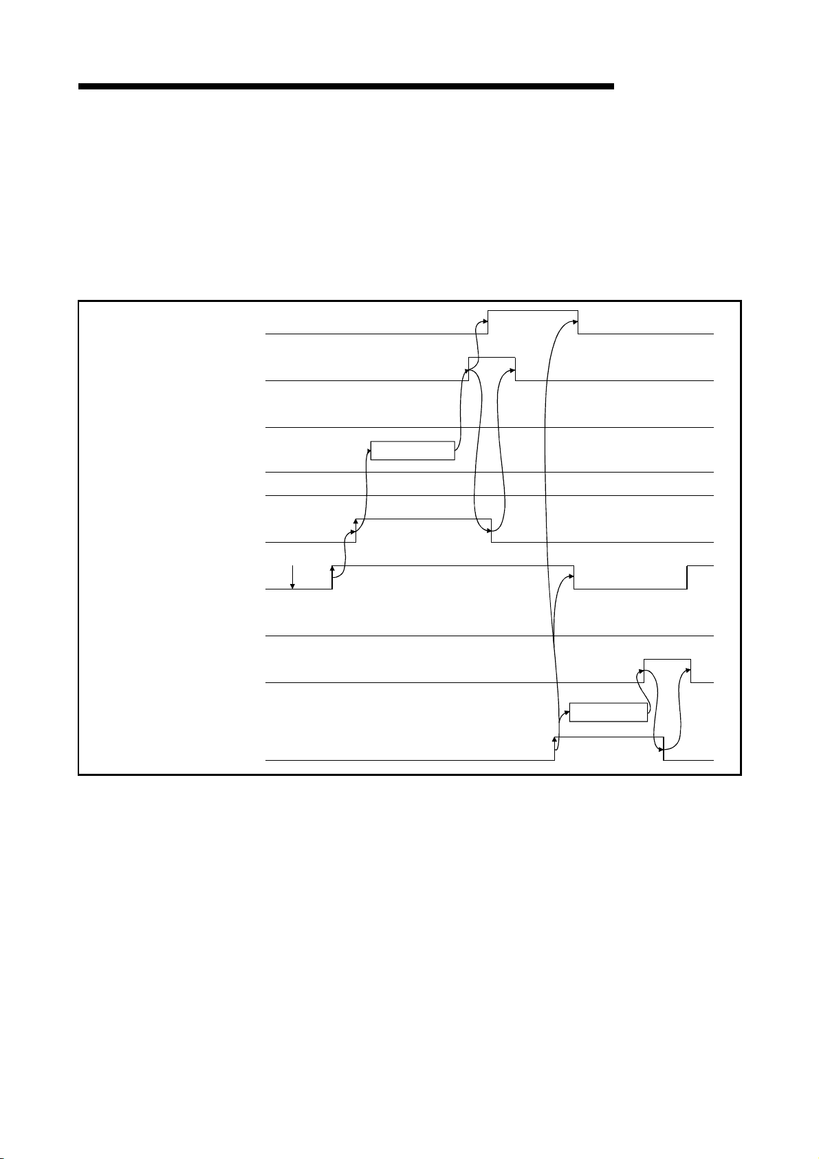
r
3 SPECIFICATION
Data link status at host station
(Xn1)
Data link startup by buffer
memory/E PROM parameter
normal completion (Xn6/Xn8)
Parameter setting status
(Xn2)
2
MELSEC-QnA
(2) Data link status at host station: Xn1
Indicates data link status at the host station.
SB006E represents the same meaning. For programming, use either Xn1 or
SB006E.
Note that the ON/OFF condition for Xn1 is opposite to that for SB006E.
When Xn1 is used, the condition is as follows:
OFF : data link stopped
ON : data link in progress
OFF
Start processing
Host parameter status
(SW0068)
Data link startup request from
buffer memory/E PROM
Parameter (Yn6/Yn8)
Module ready
(XnF)
Module erro
(Xn0)
Module reset acceptance
complete (Xn4)
Module reset request
(Yn4)
2
0
Power ON
OFF
Initialization
(3) Parameter setting status: Xn2
Indicates parameter setting status at host station.
SB006D represents the same meaning. For programming, use either Xn2 or
SB006D.
OFF : normal
ON : error in setting (An error code is stored in SW0068.)
Turns off when Yn6 or Yn8 is executed in the status that error does not
occur.
3 - 10
Page 50

3 SPECIFICATION
MELSEC-QnA
(4) Data link status at other stations: Xn3
Indicates data link status at other stations (remote/local stations).
SB0080 represents the same meaning. For programming, use either Xn3 or
SB0080.
OFF : all stations normal
ON : error station exists (An error station status is stored in SW0080 to 83.)
(5) Module reset acceptance complete: Xn4
Indicates the acceptance status of reset request by the module reset request
(Yn4).
Reset cannot be performed when module error (Xn0 on).
(a) When module reset request (Yn4) is turned on, module ready (XnF) turns off
and initialization is executed.
When the initialization is completed normally, module ready (XnF) turns on.
Module reset request (Yn4) is turned off by turning on the module reset
acceptance complete (Xn4).
To make a data link, set the data link startup request (Yn6/Yn8) again.
(Normal startup after reset)
odule reset acceptance
omplete (Xn4)
Initialization
odule ready (XnF)
odule reset request
Yn4)
3 - 11
Page 51
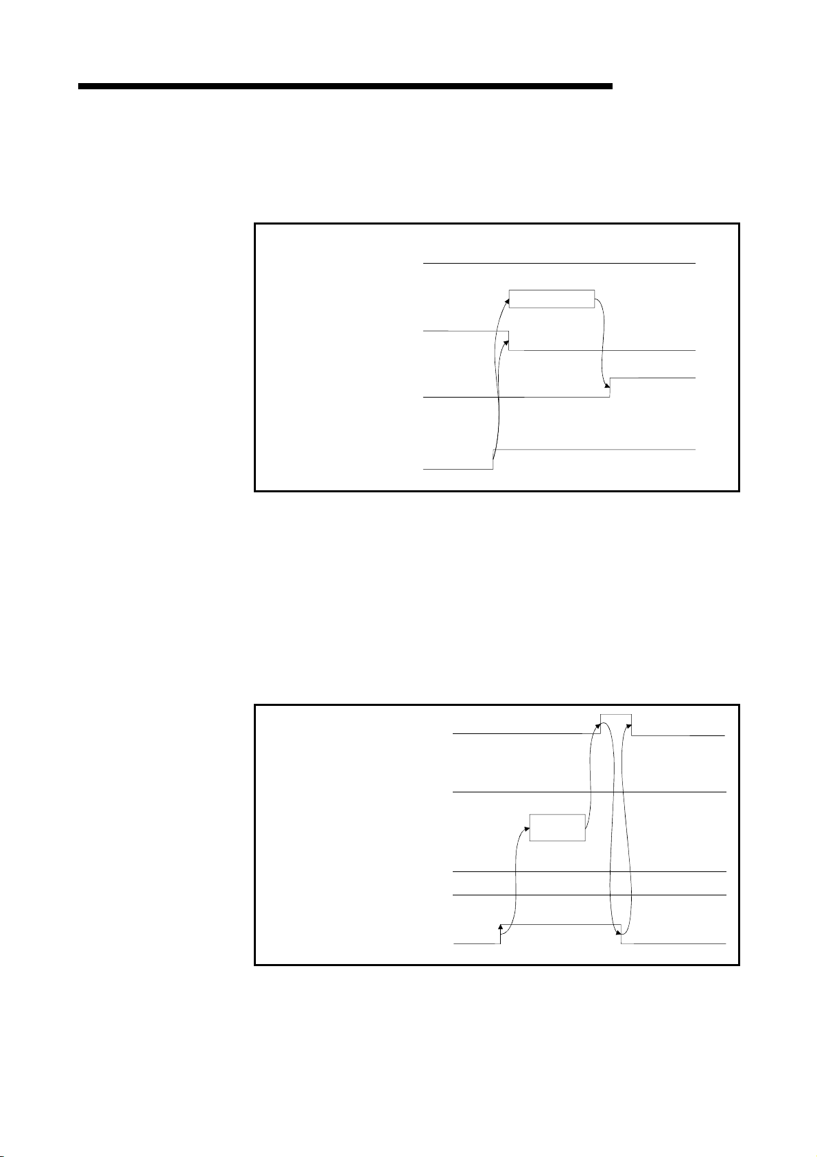
3 SPECIFICATION
MELSEC-QnA
(b) When module reset request (Yn4) is turned on, module ready (XnF) turns off
and initialization is executed.
When the initialization is completed abnormally, module ready (XnF) does not
turn on, but module error (Xn0) turns on.
(Error startup after reset)
Module reset acceptance
complete (Xn4)
Module ready (XnF)
Module error (Xn0)
OFF
Initialization
Module reset request
(Yn4)
(6) Data link startup by buffer memory parameter normal completion: Xn6
Indicates normal completion in data link startup requested by the buffer-memory
parameter data link startup request (Yn6).
(a) When (Yn6) is turned on, the parameter contents at the (address 0
H to 5FH)
in buffer memory are checked. If the check result is normal data link is started
automatically.
(b) When data link is normally started, the signal for "data link startup by buffer-
memory parameter normal completion" (Xn6) is turned on.
(c) (Xn6) is turned off by turning off (Yn6).
Data link startup by buffer-memory
parameter normal completion (Xn6)
Parameter setting status (Xn2)
OFF
Start
processing
Host station parameter status
(SW0068)
Buffer-memory parameter
data link startup request (Yn6)
0
3 - 12
Page 52
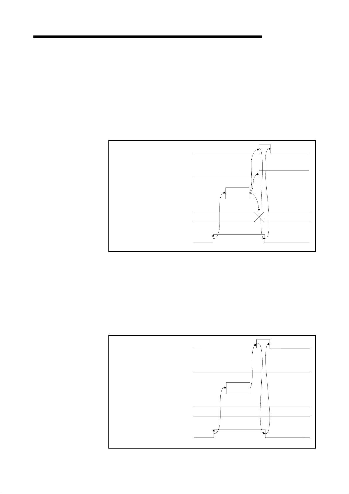
p
3 SPECIFICATION
MELSEC-QnA
(7) Data link startup by buffer memory parameter error completion: Xn7
Indicates abnormal completion in data link startup requested by the buffermemory parameter data link startup request (Yn6).
(a) When (Yn6) is turned on, the parameter contents at the (address 0
in buffer memory are checked. If error is detected the signal for "data link
startup by buffer-memory parameter abnormal completion" (Xn7) is turned on.
(b) Parameter setting status (Xn2) is turned on and the error code is stored in the
host station parameter status in buffer memory (SW0068).
(c) (Xn7) is turned off by turning off (Yn6).
Data link startup by buffer-memory
parameter error completion (Xn7)
Parameter setting status (Xn2)
Start
processing
H to 5FH)
Host station parameter status
(SW0068)
Buffer-memory parameter
data link startu
request (Yn6)
0
Error code
(8) Data link startup by E2PROM parameter normal completion: Xn8
Indicates normal completion in data link startup requested by the E2PROM
parameter data link startup request (Yn8).
(a) When (Yn8) is turned on, the E
2
PROM parameter contents are checked. If
the check result is normal data link is started automatically.
(b) When data link is normally started, the signal for "data link startup by
2
PROM parameter normal completion" (Xn8) is turned on.
E
(c) (Xn8) is turned off by turning off (Yn8).
Data link startup by E2PROM
parameter normal completion (Xn8)
Parameter setting status (Xn2)
OFF
Start
processing
Host station parameter status
(SW0068)
2
E
startup request (Yn8)
PROM parameter data link
0
3 - 13
Page 53

3 SPECIFICATION
MELSEC-QnA
(9) Data link startup by E2PROM parameter error completion: Xn9
Indicates abnormal completion in data link startup requested by the E2PROM
parameter data link startup request (Yn8).
2
(a) When (Yn8) is turned on, the E
error is detected the signal for "data link startup by E
abnormal completion" (Xn9) is turned on.
(b) Parameter setting status (Xn2) is turned on and the error code is stored in the
host station parameter status in buffer memory (SW0068).
(c) (Xn9) is turned off by turning off (Yn8).
Data link startup by E2PROM
parameter error completion (Xn9)
Parameter setting status (Xn2)
PROM parameter contents are checked. If
2
PROM parameter
Start
processing
Host station parameter status
(SW0068)
2
PROM parameter data link
E
startup request (Yn8)
0
Error code
(10) Parameter registration to E2PROM normal completion: XnA
Indicates normal completion in registering parameters at (buffer-memory address
0
H to 5FH) to E
2
E
PROM (YnA).
(a) When (YnA) is turned on, the parameter contents stored in the parameter
information area buffer memory (address 0
parameters are registered to E
(b) When registration is normally completed, the signal for "parameter registration
to E
2
(c) (XnA) is turned off by turning off (YnA).
Parameter registration to E2PROM
normal completion (XnA)
2
PROM requested by the parameter registration request to
2
PROM.
H to 5FH) are checked. If the
PROM normal completion" (XnA) is turned on.
Registration
processing
2
Registration to E
(SW00B9)
Parameter registration request to
2
E
PROM (YnA).
PROM status
0
3 - 14
Page 54
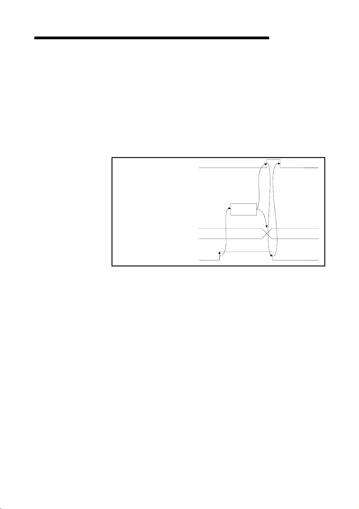
3 SPECIFICATION
MELSEC-QnA
(11) Parameter registration to E2PROM error completion: XnB
Indicates abnormal completion in registering parameters at (buffer-memory
address 0
to E
H to 5FH) to E
2
PROM (YnA).
(a) When the parameter registration request (YnA) to the E
the parameters stored in the buffer-memory "parameter information area
(address 0
H to 5FH)" are written to the E
(b) When the registration ends error, the E
(XnB) turns on and the error code is stored in the buffer memory E
registration status (SW00B9).
(c) (XnB) is turned off by turning off (YnA).
Parameter registration to E2PROM
error completion (XnB)
2
PROM requested by the parameter registration request
2
PROM is turned on,
2
PROM.
2
PROM parameter registration error
2
PROM
Registration
processing
Registration to E
(SW00B9)
Parameter registration request to
2
PROM (YnA).
E
2
PROM status
0
Error code
3 - 15
Page 55

)
)
3 SPECIFICATION
MELSEC-QnA
(12) E2PROM erasure normal completion: XnD
This signal indicates the normal completion of erasing the parameters in the
2
E
PROM in response to the E2PROM erasure request (YnD).
(a) When the E
2
E
PROM are erased.
(b) On normal completion of erasure, the E
(XnD) turns on.
(c) By turning off the E
normal completion (XnD) turns off.
2
E2PROM erasure normal completion
(XnD)
2
PROM erasure request (YnD) turns on, the parameters in the
2
PROM erasure normal completion
2
PROM erasure request (YnD), the E2PROM erasure
Erasure
processing
2
2
PROM erasure result
E
(SW00BA)
2
E2PROM erasure request
YnD
0
(13) E2PROM erasure abnormal completion: XnE
This signal indicates the abnormal completion of erasing the parameters in the
2
PROM in response to the E2PROM erasure request (YnD).
E
(a) When the E
2
PROM are erased.
E
(b) On abnormal completion of erasure, the E
completion (XnE) turns on and the error code is stored into the E
erasure result (SW00BA) of the buffer memory.
(c) By turning off the E
abnormal completion (XnE) turns off.
2
E2PROM erasure abnormal completion
(XnE)
2
PROM erasure request (YnD) turns on, the parameters in the
2
PROM erasure abnormal
2
PROM erasure request (YnD), the E2PROM erasure
2
PROM
Erasure
processing
2
2
PROM erasure result
E
(SW00BA)
2
E2PROM erasure request
YnD
0
Error code
3 - 16
Page 56

3 SPECIFICATION
MELSEC-QnA
(14) Module ready: XnF
Indicates if the module is ready for operation.
(a) Turns on automatically when the module becomes ready for operation
Used as an interlock signal when a sequence program is used to make
access to the master/local module.
(b) Turns off when one of the following conditions occur:
• There is an error in the module switch settings.
• The module reset request signal (Yn4) is turned on.
• The module error signal (Xn0) is turned on.
Power supply ON
Module ready
(XnF)
Module error
(Xn0)
Module reset request
Yn4)
(15) Refresh instruction: Yn0
Indicates if the content of remote output RY (address 160H to 1DFH) in the buffer
memory is effective or not. Same meaning for local stations.
For remote input RX and remote register RWr/RWw except remote output RY,
refresh is continued independently of this signal.
OFF : Not effective (Sends all-off data.)
ON : Effective (Sends data in "remote output (address 160
Master station Remote I/O station
Remote input (RX)
Remote output (RY)
buffer memory.)
Input
Output
Remote device station
Remote input (RX)
Remote output (RY)
H to 1DFH)" in the
Local station
Remote output (RY)
Remote input (RX)
POINT
(1) Yn0 is set (on) before the data link start up.
(2) Yn0 is turned off when the programmable controller CPU is in the STOP status.
3 - 17
Page 57

3 SPECIFICATION
MELSEC-QnA
(16) Module reset request: Yn4
Signal used to reset the module for debugging.
The module can be reset individually without resetting the programmable
controller CPU.
If you cannot start the remote station earlier than starting the system in any
method, resetting the module after the start of the remote station allows the
system to start from the initial status securely.
Refer to (5) for signal timing.
(17) Data link startup request from buffer memory parameter: Yn6
Starts data link according to the parameter (address 0H to 5FH) contents in buffer
memory.
Do not turn on this signal during RUN of the programmable controller CPU and
during a data link.
If you are going to change any parameter data during RUN of the programmable
controller CPU and during a data link, always turn on SB0002 (data link stop) to
stop the data link, change the parameter data, and then turn on this signal to
restart the data link.
Refer to (6) and (7) for signal timing.
(18) Data link startup request from E2PROM parameter: Yn8
Starts data link according to the parameter contents registered in E2PROM.
Do not turn on this signal during RUN of the programmable controller CPU and
during a data link.
If you are going to change any parameter data during RUN of the programmable
controller CPU and during a data link, always turn on SB0002 (data link stop) to
stop the data link, change the parameter data, and then turn on this signal to
restart the data link.
Refer to (8) and (9) for signal timing.
POINT
The factory-set E2PROM values are inconsistent.
Before executing a data link start with the Yn8 signal, always execute parameter
registration with the YnA signal at least once.
(19) Parameter registration request to E2PROM: YnA
The signal for registering parameter (address 0H to 5FH) in buffer memory to
2
E
PROM.
Refer to (10) and (11) for signal timing.
Since parameter registration to E
parameter registration with the YnA signal a minimum required number of times.
2
PROM is limited to 10,000 times, execute
(20) E2PROM erasure request: YnD
The signal for erasing the parameters in the E2PROM.
Refer to (12) and (13) for the signal timing.
3 - 18
Page 58

3 SPECIFICATION
3.5 Buffer Memory
The buffer memory is used to swap data between the master/local module and the
programmable controller CPU.
In the programmable controller CPU, the FROM/TO instructions are used to read/write
data.
The contents of the buffer memory return to the default values when the power is
turned off and the programmable controller CPU is reset.
3.5.1 Buffer memory list
The buffer memory list is shown in Table 3.4.
When using a master/local module as a standby master station, refer to the respective
columns under "Availability" in the table as explained below.
x When a standby master station is operating as a master station: "Master station"
column
x When a standby master station is operating as a standby master station: "Local
station" column
Address Availability
Hex. Dec.
0H to
5F
H
60H to
7F
H
80H to
CD
H
CEH to
DF
H
E0H to
15F
H
160H
to
1DF
H
1E0H
to
2DF
H
* Do not write to areas that are prohibited to use. An error may occur.
Parameter information
0 to 95
area
96 to
127
128 to
Parameter information
205
area
206 to
223
224 to
Remote input (RX)
351
352 to
Remote output (RY)
479
Remote register (RWw)
(Master station:
480 to
for sending
735
Local station:
for sending/receiving)
Item Details
(Prohibited to use)
(Prohibited to use)
– – – – –
– – – – –
Table 3.4 Buffer memory list (1/2)
Stores the information (parameters)
to execute the data link.
Stores the information (parameters)
to execute the data link.
When master station: Stores the
input status from the remote/local
station.
When local station: stores the input
status from the master station.
When master station: Stores the
output status of the output to the
remote/local station.
When local station: Stores the output
status of the output to the master
station.
When master station: Stores the
transmission data to the remote/all
local stations.
When local station: Stores the
transmission data to the
master/other local stations. Also,
stores the received data from the
remote/other local stations.
Read/write
possibility
Read/write
enabled
Read/write
enabled
Read only
Write only
Read/write
enabled
Write only
Read/write
enabled
Master station
(Not available when a
standby master station is
controlling the system)
(Not available when a
standby master station is
controlling the system)
MELSEC-QnA
Local
station
–
–
–
: Usable : Prohibited to use
–
–
–
Reference
Section
3.5.2 (1)
Section
15.2.1
Section
3.5.2 (2)
Section
3.5.2 (3)
3 - 19
Page 59

3 SPECIFICATION
Address Availability
Hex. Dec.
Remote register (RWr)
2E0H
to
3DF
H
736 to
991
(Master station:
for receiving
Local station:
for receiving)
3E0H
992 to
to
1503
5DF
H
5E0H
1504
to
to
Link special relay (SB) Stores the data-link status.
5FF
H
1535
600H
1536
to
7FF
800H
to
9FF
A00H
to
FFF
1000H
to
1FFF
2000H
to
2FFF
H
H
H
H
H
Link special register
to
(SW)
2047
2048
to
2559
2560
Random access buffer
to
4095
4096
Transmission and
to
receiving buffer
8191
8192
Automatic updating
to
buffer
12287
Do not write to areas that are prohibited to use. An error may occur.
Item Details
(Prohibited to use)
(Prohibited to use)
– – – – –
– – – – –
Table 3.4 Buffer memory list (2/2)
When master station: Stores the
received data from the remote/local
station.
When local station: Stores the
received data from the master
station.
Stores the data-link status.
Uses for dedicated instruction of
RIRD, RIWT, etc.
Stores the transmission and received
data and the control data when a
transient transmission
(communication using the
transmission and receiving buffer) is
made with the intelligent device
stations.
The area for each intelligent device
station is set with the network
parameters.
Stores the automatic updating data
when a transient transmission
(communication using the automatic
updating buffer) is made with the
intelligent device stations.
The area for each intelligent device
station is set with the network
parameters.
Read/write
possibility
Read only
Read/write
enabled
(write
disabled
depending
on the
device)
Read/write
enabled
Read/write
enabled
Read/write
enabled
Master station
MELSEC-QnA
Reference
Local
station
–
Section
3.5.2 (3)
Section
3.5.2 (4)
Section
3.5.2 (5)
–
Section
15.6
Section
15.2.1
Section
15.2.1
: Usable : Prohibited to use
3 - 20
Page 60

3 SPECIFICATION
MELSEC-QnA
3.5.2 Buffer memory details
The details of each item shown in Table 3.4 of Section 3.5.1 is described.
(1) Parameter information area
The conditions to perform data link is set.
Also, these can be registered in the E
Address
Hex. Dec.
0H 0 (Prohibited to use) – –
1H 1
2H 2 Number of retries Set the number of retries to the communication faulty station. 3
3H 3
4H 4 (Prohibited to use) – –
5H 5 (Prohibited to use) – –
6H 6
7H to FH 7 to 15 (Prohibited to use) – –
10H to 13H 16 to 19
14H to 17H 20 to 23
18H to 1FH 24 to 31 (Prohibited to use) – –
20H to 5FH 32 to 95 Station information Set the connected remote/local station type.
Do not write to areas that are prohibited to use. An error may occur.
Number of connected
modules
Number of automatic
return modules
Operation specification
when CPU is down
Reserved station
specification
Invalid station
specification
Item Description Default
Table 3.5 Parameter information area list
Set the number of connected remote/local station modules.
(including reserved stations)
Set the number of remote/local stations modules that can
return with 1 link scan.
Specify the data-link status when there is a master station
programmable controller CPU error.
Set a reserved station. 0 (No specification)
Specify an invalid station. 0 (No specification)
2
PROM.
64
1
0 (Stop)
Station type: Remote I/O
station
Number of occupied
stations: 1
Station numbers: 1 to 64
(a) Number of connected modules
This sets the number of remote/local station modules connected to the
master station (including reserved stations).
This is not a station count.
The setting range is "1 to 64 (modules)."
POINT
The station information (address 20H to 5FH) for the specified "number of connected" stations
becomes valid.
(b) Number of retries
This sets the number of retries to the remote/local station with a data link
error.
The setting range is "1 to 7 (times)."
If the remote/local station cannot recover a normal data link after
performing specified number of retries, the station becomes a "data-link
faulty station."
3 - 21
Page 61

3 SPECIFICATION
MELSEC-QnA
(c) Number of automatic return modules
This sets the number of remote/local stations that can return to the system
during 1 link scan.
The range is "1 to 10 (modules)."
(d) Operation specification when CPU is down
This specifies the data-link status when the master station programmable
controller CPU has an error which "stops the error operation".
"0" is stop and "1" is continue.
(e) Reserved station specification
This is set to include the remote/local stations that are not actually
connected in the number of connected modules, so that a data link error
does not occur.
1
When a connected remote/local station is set as a reserved station, the
station cannot perform any data link at all.
2
Turn on the bit corresponding to the station number to be set as
reserved.
However, for the remote/local station that occupies more than 2 stations,
turn on the only bit for the station numbers set by the module's station
number setting switch.
Address b15 b14 b13 b12 b11 b10 b9 b8 b7 b6 b5 b4 b3 b2 b1 b0
10
H 16 15 14 13 12 11 10 9 8 7 6 5 4 3 2 1
11H 32 31 30 29 28 27 26 25 24 23 22 21 20 19 18 17
12H 48 47 46 45 44 43 42 41 40 39 38 37 36 35 34 33
13H 64 63 62 61 60 59 58 57 56 55 54 53 52 51 50 49
1 to 64 in the table below indicate the station numbers.
<Setting example>
When setting a local station with station number 4 and a remote station
with station number 9 as reserved in the system configuration below:
Stations to be connected in the future
Station No.4
Master
station
Station No.1
Remote station
(occupies 2 stations)
Station No.3
Remote station
(occupies 1 station)
Local station
(occupies 4
stations)
Station No.8
Remote station
(occupies 1 station)
Station No.9
Remote station
(occupies 1 station)
Address b15 b14 b13 b12 b11 b10 b9 b8 b7 b6 b5 b4 b3 b2 b1 b0
H 0 0 0 0 0 0 0 1 0 0 0 0 1 0 0 0
10
11H 0 0 0 0 0 0 0 0 0 0 0 0 0 0 0 0
12H 0 0 0 0 0 0 0 0 0 0 0 0 0 0 0 0
13H 0 0 0 0 0 0 0 0 0 0 0 0 0 0 0 0
3 - 22
Page 62

3 SPECIFICATION
MELSEC-QnA
(f) Error invalid station specification
This is set so that the remote/local station that can no longer perform data
link due to power off, etc. will not be treated as a "data-link faulty station" on
the master station and the local station.
Be careful, however, for errors will not be detected.
1
When the same station number is specified as a reserved station, the
reserved station specification has the priority.
2
Turn on the bit corresponding to the station number of the invalid station.
However, for remote/local stations that occupy more than 2 stations, turn
on the only bit for the station numbers set by the module's station
number setting switch.
Address b15 b14 b13 b12 b11 b10 b9 b8 b7 b6 b5 b4 b3 b2 b1 b0
14
H 16 15 14 13 12 11 10 9 8 7 6 5 4 3 2 1
15H 32 31 30 29 28 27 26 25 24 23 22 21 20 19 18 17
16H 48 47 46 45 44 43 42 41 40 39 38 37 36 35 34 33
17H 64 63 62 61 60 59 58 57 56 55 54 53 52 51 50 49
1 to 64 in the table below indicate the station numbers.
<Setting example>
When setting a local station with station number 4 and a remote station
with station number 9 as invalid in the system configuration below:
Set as invalid stations
Station No.4
Master
station
Station No.1
Remote station
(occupies 2 stations)
Station No.3
Remote station
(occupies 1 station)
Local station
(occupies 4
stations)
Station No.8
Remote station
(occupies 1 station)
Station No.9
Remote station
(occupies 1 station)
Address b15 b14 b13 b12 b11 b10 b9 b8 b7 b6 b5 b4 b3 b2 b1 b0
H 0 0 0 0 0 0 0 1 0 0 0 0 1 0 0 0
10
11H 0 0 0 0 0 0 0 0 0 0 0 0 0 0 0 0
12H 0 0 0 0 0 0 0 0 0 0 0 0 0 0 0 0
13H 0 0 0 0 0 0 0 0 0 0 0 0 0 0 0 0
3 - 23
Page 63

3 SPECIFICATION
MELSEC-QnA
(g) Station information
This sets the remote/local station type for connected remote/local stations
and reserved stations.
1
The data configuration to be set is shown below.
b15 b12tob11 b8tob7 b0
to
Station type
Number of
occupied stations
Station number
1: occupies 1 station
2: occupies 2 stations
3: occupies 3 stations
4: occupies 4 stations
0: Remote I/O station
1: Remote device station
2
The buffer memory address for each module is shown in the table
2: Intelligent device station (including local station)
1 to 64
(01
H to 40H)
below.
For example, when setting for the 25th module, write to the buffer
Module Address Module Address Module Address Module Address
1st module 20H 17th module 30H 33rd module 40H 49th module 50H
2nd module 21H 18th module 31H 34th module 41H 50th module 51H
3rd module 22H 19th module 32H 35th module 42H 51st module 52H
4th module 23H 20th module 33H 36th module 43H 52nd module 53H
5th module 24H 21st module 34H 37th module 44H 53rd module 54H
6th module 25H 22nd module 35H 38th module 45H 54th module 55H
7th module 26H 23rd module 36H 39th module 46H 55th module 56H
8th module 27H 24th module 37H 40th module 47H 56th module 57H
9th module 28H 25th module 38H 41st module 48H 57th module 58H
10th module 29H 26th module 39H 42nd module 49H 58th module 59H
11th module 2AH 27th module 3AH 43rd module 4AH 59th module 5AH
12th module 2BH 28th module 3BH 44th module 4BH 60th module 5BH
13th module 2CH 29th module 3CH 45th module 4CH 61st module 5CH
14th module 2DH 30th module 3DH 46th module 4DH 62nd module 5DH
15th module 2EH 31st module 3EH 47th module 4EH 63rd module 5EH
16th module 2FH 32nd module 3FH 48th module 4FH 64th module 5FH
memory address "38
H."
<Setting example>
When connecting a remote I/O station, a remote device station and a
station
local station:
3rd module
Local station
Station No.4
(occupies 4
stations)
Address
20
21H
22H
type
0
1H
2H
H
Number of
occupied
stations
1
H
2H
4H
Station number
01
H
02H
04H
Station
H
<<System configuration example>> <<Station information setting>>
Master
station
1st module
Remote I/O
station
Station No.1
(occupies 1 station)
2nd module
Remote device
Station No.2
(occupies 2 stations)
3 - 24
Page 64

3 SPECIFICATION
Master station
MELSEC-QnA
(2) Remote input (RX) and remote output (RY)
(a) Master station Remote I/O station/remote device station/
local station
1
Master station
• Input status from remote I/O station, remote device station (RX) and
local station (RY) are stored.
• Two words are used per station.
Remote I/O station
(station No.1: occupies 1 station)
Remote device station
(station No.2: occupies 2 stations)
For station No.1
For station No.2
For station No.3
For station No.4
For station No.5
For station No.6
For station No.7
For station No.8
For station No.9
For station No.63
For station No.64
Address
E0
E1H
E2H
E3H
E4H
E5H
E6H
E7H
E8H
E9H
EAH
EB
ECH
ED
EEH
EF
F0
F1
F2H
to
15BH
15CH
15DH
15EH
15FH
Remote input (RX)
H
RX F to RX 0
RX 1F to RX 10
RX 2F to RX 20
RX 3F to RX 30
RX 4F to RX 40
RX 5F to RX 50
RX 6F to RX 60
RX 7D to RX 70
RX 8F to RX 80
RX 9F to RX 90
RX AF to RX A0
H
RX BF to RX B0
RX CF to RX C0
H
RX DF to RX D0
RX EF to RX E0
H
RX FD to RX F0
H
RX10F to RX100
H
RX11F to RX110
RX7CF to RX7C0
RX7DF to RX7D0
RX7EF to RX7E0
RX7FF to RX7F0
X0F to X00
X1F to X10
to
Remote input (RX)
RX0F to RX00
RX1F to RX10
Station
number
Buffer memory
1 E0H to E1H 14 FAH to FBH 27 114H to 115H 40 12EH to 12FH 53 148H to 149H
2 E2H to E3H 15 FCH to FDH 28 116H to 117H 41 130H to 131H 54 14AH to 14BH
3 E4H to E5H 16 FEH to FFH 29 118H to 119H 42 132H to 133H 55 14CH to 14DH
4 E6H to E7H 17 100H to 101H 30 11AH to 11BH 43 134H to 135H 56 14EH to 14FH
5 E8H to E9H 18 102H to 103H 31 11CH to 11DH 44 136H to 137H 57 150H to 151H
6 EAH to EBH 19 104H to 105H 32 11EH to 11FH 45 138H to 139H 58 152H to 153H
7 ECH to EDH 20 106H to 107H 33 120H to 121H 46 13AH to 13BH 59 154H to 155H
8 EEH to EFH 21 108H to 109H 34 122H to 123H 47 13CH to 13DH 60 156H to 157H
9 F0H to F1H 22 10AH to 10BH 35 124H to 125H 48 13EH to 13FH 61 158H to 159H
10 F2H to F3H 23 10CH to 10DH 36 126H to 127H 49 140H to 141H 62 15AH to 15BH
11 F4H to F5H 24 10EH to 10FH 37 128H to 129H 50 142H to 143H 63 15CH to 15DH
12 F6H to F7H 25 110H to 111H 38 12AH to 12BH 51 144H to 145H 64 15EH to 15FH
13 F8H to F9H 26 112H to 113H 39 12CH to 12DH 52 146H to 147H – –
Master station's buffer memory and station number correspondence table
address
Station
number
Buffer memory
address
Station
number
Buffer memory
address
Station
number
Buffer memory
address
Station
number
Buffer memory
address
3 - 25
Page 65
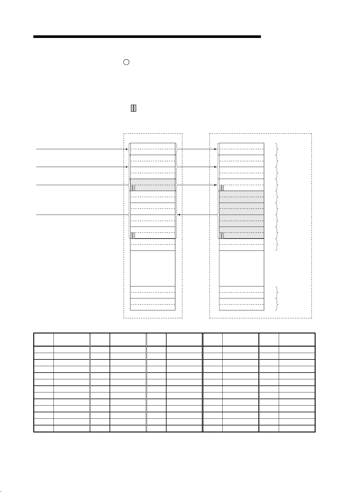
3 SPECIFICATION
MELSEC-QnA
2
Local station
• Data to be sent to master station is stored in the remote output (RY)
corresponding to the host station.
• Input status from remote I/O station, remote device station (RX) and
other local station are stored.
• Two words are used per station.
... The last 2 bits cannot be used when the master station and the
local station are communicating.
(station No.4: occupies 1 station)
Local station
RY F to RY 0
RY 1F to RY 10
RY 2F to RY 20
RY 3F to RY 30
RY 4F to RY 40
RY 5F to RY 50
RY 6F to RY 60
RY 7D to RY 70
RY 8F to RY 80
RY 9F to RY 90
RY AF to RY A0
RY BF to RY B0
RY CF to RY C0
RY DF to RY D0
RY EF to RY E0
RY FD to RY F0
RY10F to RY100
RY11F to RY110
(station No.5: occupies 4 stations)
Remote output (RY) AddressRemote output (RY)
RY F to RY 0
RY 1F to RY 10
RY 2F to RY 20
RY 3F to RY 30
RY 4F to RY 40
RY 5F to RY 50
RY 6F to RY 60
RY 7D to RY 70
RY 8F to RY 80
RY 9F to RY 90
RY AF to RY A0
RY BF to RY B0
RY CF to RY C0
RY DF to RY D0
RY EF to RY E0
RY FD to RY F0
RY10F to RY100
RY11F to RY110
Local station
160
161H
162H
163H
164
165H
166H
167H
168
169
16AH
16BH
16C
16D
16EH
16F
170
171H
172H
H
For station No.1
For station No.2
H
For station No.3
For station No.4
H
For station No.5
H
For station No.6
H
For station No.7
H
For station No.8
H
H
For station No.9
to
RY7CF to RY7C0
RY7DF to RY7D0
RY7EF to RY7E0
RY7FF to RY7F0
to to
RY7CF to RY7C0
RY7DF to RY7D0
RY7EF to RY7E0
RY7FF to RY7F0
1DB
1DCH
1DDH
1DEH
1DF
H
H
For station No.63
For station No.64
Station
number
1 160H to 161H 14 17AH to 17BH 27 194H to 195H 40 1AEH to 1AFH 53 1C8H to 1C9H
2 162H to 163H 15 17CH to 17DH 28 196H to 197H 41 1B0H to 1B1H 54 1CAH to 1CBH
3 164H to 165H 16 17EH to 17FH 29 198H to 199H 42 1B2H to 1B3H 55 1CCH to 1CDH
4 166H to 167H 17 180H to 181H 30 19AH to 19BH 43 1B4H to 1B5H 56 1CEH to 1CFH
5 168H to 169H 18 182H to 183H 31 19CH to 19DH 44 1B6H to 1B7H 57 1D0H to 1D1H
6 16AH to 16BH 19 184H to 185H 32 19EH to 19FH 45 1B8H to 1B9H 58 1D2H to 1D3H
7 16CH to 16DH 20 186H to 187H 33 1A0H to 1A1H 46 1BAH to 1BBH 59 1D4H to 1D5H
8 16EH to 16FH 21 188H to 189H 34 1A2H to 1A3H 47 1BCH to 1BDH 60 1D6H to 1D7H
9 170H to 171H 22 18AH to 18BH 35 1A4H to 1A5H 48 1BEH to 1BFH 61 1D8H to 1D9H
10 172H to 173H 23 18CH to 18DH 36 1A6H to 1A7H 49 1C0H to 1C1H 62 1DAH to 1DBH
11 174H to 175H 24 18EH to 18FH 37 1A8H to 1A9H 50 1C2H to 1C3H 63 1DCH to 1DDH
12 176H to 177H 25 190H to 191H 38 1AAH to 1ABH 51 1C4H to 1C5H 64 1DEH to 1DFH
13 178H to 179H 26 192H to 193H 39 1ACH to 1ADH 52 1C6H to 1C7H – –
Local station's buffer memory address and station number correspondence table
Buffer memory
address
Station
number
Buffer memory
address
Station
number
Buffer memory
address
Station
number
Buffer memory
address
Station
number
Buffer memory
address
3 - 26
Page 66

3 SPECIFICATION
Master station
Address
For station No.1
For station No.2
For station No.3
For station No.4
For station No.5
For station No.6
For station No.7
For station No.8
For station No.9
Remote output (RY) Remote output (RY)
160H
RY F
161
H
162H
163
H
164H
RY 4F
165
H
166
H
RY 6F
167
H
RY 7D
168
H
RY 8F
169
H
16A
H
RY AF
16BH
RY BF
16C
H
RY CF
16DH
16E
H
16FH
RY FD
170
H
171H
172
H
MELSEC-QnA
(b) Master station remote I/O station/remote device station/local
station
1
Master station
• Output status to remote I/O station, remote device station (RY) and all
local stations (RX) are stored.
• Two words are used per station.
10F RY
to
RY 0
to RY 1F RY 10
to RY 2F RY 20
to RY 3F RY 30
to
RY 40
RY 50
to RY 5F
to
RY 60
to
RY 70
to
RY 80
to RY 9F RY 90
to
RY A0
to
RY B0
to
RY C0
to RY DF RY D0
to RY EF RY E0
to
RY F0
to
RY 100
toRY11F 110RY
Remote I/O station
(station No.1: occupies 1 station)
to Y0F Y00
Y1F Y10
to
Remote device station
(station No.2: occupies 2 stations)
to RY0F RY00
toRY1F RY10
toto
1DB
H
RY7CF RY7C0to
For station No.63
For station No.64
1DCH
1DDH
1DE
1DFH
H
RY7DF
to
RY7EF RY7E0
RY7FF
RY7D0
to
RY7F0to
Station
number
Buffer memory
1 160H to 161H 14 17AH to 17BH 27 194H to 195H 40 1AEH to 1AFH 53 1C8H to 1C9H
2 162H to 163H 15 17CH to 17DH 28 196H to 197H 41 1B0H to 1B1H 54 1CAH to 1CBH
3 164H to 165H 16 17EH to 17FH 29 198H to 199H 42 1B2H to 1B3H 55 1CCH to 1CDH
4 166H to 167H 17 180H to 181H 30 19AH to 19BH 43 1B4H to 1B5H 56 1CEH to 1CFH
5 168H to 169H 18 182H to 183H 31 19CH to 19DH 44 1B6H to 1B7H 57 1D0H to 1D1H
6 16AH to 16BH 19 184H to 185H 32 19EH to 19FH 45 1B8H to 1B9H 58 1D2H to 1D3H
7 16CH to 16DH 20 186H to 187H 33 1A0H to 1A1H 46 1BAH to 1BBH 59 1D4H to 1D5H
8 16EH to 16FH 21 188H to 189H 34 1A2H to 1A3H 47 1BCH to 1BDH 60 1D6H to 1D7H
9 170H to 171H 22 18AH to 18BH 35 1A4H to 1A5H 48 1BEH to 1BFH 61 1D8H to 1D9H
10 172H to 173H 23 18CH to 18DH 36 1A6H to 1A7H 49 1C0H to 1C1H 62 1DAH to 1DBH
11 174H to 175H 24 18EH to 18FH 37 1A8H to 1A9H 50 1C2H to 1C3H 63 1DCH to 1DDH
12 176H to 177H 25 190H to 191H 38 1AAH to 1ABH 51 1C4H to 1C5H 64 1DEH to 1DFH
13 178H to 179H 26 192H to 193H 39 1ACH to 1ADH 52 1C6H to 1C7H – –
Master station's buffer memory and station number correspondence table
address
Station
number
Buffer memory
address
Station
number
Buffer memory
address
Station
number
Buffer memory
address
Station
number
Buffer memory
address
3 - 27
Page 67

3 SPECIFICATION
MELSEC-QnA
2
Local station
• Data received from remote I/O station, remote device station (RY) and
master station (RY) are stored.
• Two words are used per station.
... The last 2 bits cannot be used when the master station and the
local station are communicating.
Local station
(station No.4: occupies 1 station)
Remote input (RX)
to RX F RX 0
to RX 1F RX 10
to RX 2F RX 20
to RX 3F RX 30
to
RX 4F
RX 6F
RX 7D
RX 9F
RX AF
RX BF
RX 40
to RX 5F RX 50
to
RX 60
to
RX 70
to RX 8F RX 80
to
RX 90
to
RX A0
to
RX B0
to RX CF RX C0
to RX DF RX D0
RX E0
to RX EF
to RX FD RX F0
to 10F RX RX 100
110RX
toRX11F
(station No.5: occupies 4 stations)
Remote input (RX) Address
RX 4F
RX 6F
RX 7D
RX 9F
RX AF
RX BF
RX11F
Local station
RX 40
RX 60
RX 70
RX 90
RX A0
RX B0
RX E0
110RX
E0H
E1H
E2H
E3
E4
E5
E6
E7H
E8H
E9
EA
EB
EC
EDH
EEH
EFH
F0H
F1H
F2
to RX F RX 0
to RX 1F RX 10
to RX 2F RX 20
to RX 3F RX 30
to
to RX 5F RX 50
to
to
to RX 8F RX 80
to
to
to
to RX CF RX C0
to RX DF RX D0
to RX EF
to RX FD RX F0
to 10F RX RX 100
to
For station No.1
For station No.2
H
H
For station No.3
H
H
For station No.4
For station No.5
H
H
For station No.6
H
H
For station No.7
For station No.8
For station No.9
H
to
RX7CF
RX7DF RX7D0to
RX7EF RX7E0to
RX7FF RX7F0to
to
RX7C0
to
RX7CF
RX7DF RX7D0to
RX7EF RX7E0to
RX7FF RX7F0to
to
RX7C0
to
15B
15C
For station No.63
15D
15E
For station No.64
15F
Station
number
1 E0H to E1H 14 FAH to FBH 27 114H to 115H 40 12EH to 12FH 53 148H to 149H
2 E2H to E3H 15 FCH to FDH 28 116H to 117H 41 130H to 131H 54 14AH to 14BH
3 E4H to E5H 16 FEH to FFH 29 118H to 119H 42 132H to 133H 55 14CH to 14DH
4 E6H to E7H 17 100H to 101H 30 11AH to 11BH 43 134H to 135H 56 14EH to 14FH
5 E8H to E9H 18 102H to 103H 31 11CH to 11DH 44 136H to 137H 57 150H to 151H
6 EAH to EBH 19 104H to 105H 32 11EH to 11FH 45 138H to 139H 58 152H to 153H
7 ECH to EDH 20 106H to 107H 33 120H to 121H 46 13AH to 13BH 59 154H to 155H
8 EEH to EFH 21 108H to 109H 34 122H to 123H 47 13CH to 13DH 60 156H to 157H
9 F0H to F1H 22 10AH to 10BH 35 124H to 125H 48 13EH to 13FH 61 158H to 159H
10 F2H to F3H 23 10CH to 10DH 36 126H to 127H 49 140H to 141H 62 15AH to 15BH
11 F4H to F5H 24 10EH to 10FH 37 128H to 129H 50 142H to 143H 63 15CH to 15DH
12 F6H to F7H 25 110H to 111H 38 12AH to 12BH 51 144H to 145H 64 15EH to 15FH
13 F8H to F9H 26 112H to 113H 39 12CH to 12DH 52 146H to 147H – –
Local station's buffer memory address and station number correspondence table
Buffer memory
address
Station
number
Buffer memory
address
Station
number
Buffer memory
address
Station
number
Buffer memory
address
Station
number
Buffer memory
address
3 - 28
Page 68
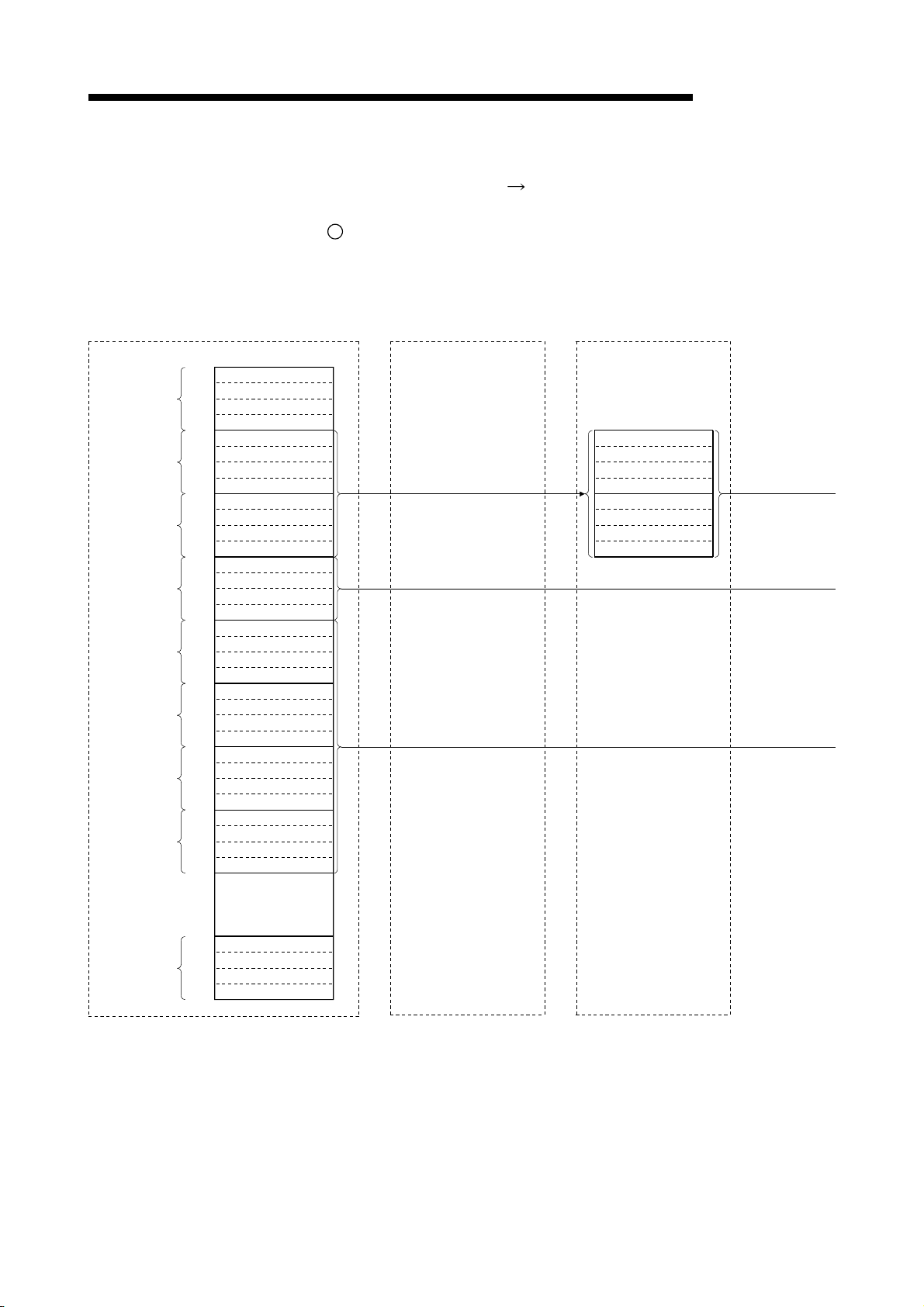
3 SPECIFICATION
Master station
Remote register (RWw)
1E0H
1E1
H
H
1E2
1E3
H
1E4H
1E5
H
1E6H
1E7H
1E8H
1E9H
1EAH
1EBH
1EC
H
1EDH
1EE
H
1EFH
1F0
H
1F1
H
1F2
H
1F3
H
1F4
H
1F5
H
1F6H
1F7
H
1F8H
1F9
H
1FAH
1FBH
1FCH
1FDH
1FEH
1FFH
200
H
to
H
2DB
2DC
H
2DDH
2DE
H
2DFH
For station No.1
For station No.2
For station No.3
For station No.4
For station No.5
For station No.6
For station No.7
For station No.8
For station No.64
Address
(3) Remote register (RWw) and remote register (RWr)
(a) Master station (RWw) Remote device station (RWw)/
local station (RWr)
1
Master station
• Data to be sent to remote register at remote device station (RWw) and
remote registers of all local stations (RWr) are stored.
• Four words are used per station.
RWw 0
RWw 1
RWw 2
RWw 3
RWw 4
RWw 5
RWw 6
RWw 7
RWw 8
RWw 9
RWw A
RWw B
RWw C
RWw D
RWw E
RWw F
RWw 10
RWw 11
RWw 12
RWw 13
RWw 14
RWw 15
RWw 16
RWw 17
RWw 18
RWw 19
RWw 1A
RWw 1B
RWw 1C
RWw 1D
RWw 1E
RWw 1F
to
RWw FC
RWw FD
RWw FE
RWw FF
Remote I/O station
(station No.1: occupies 1 station)
Remote device station
(station No.2: occupies 2 stations)
Remote register (RWw)
RWw0
RWw1
RWw2
RWw3
RWw4
RWw5
RWw6
RWw7
MELSEC-QnA
3 - 29
Page 69
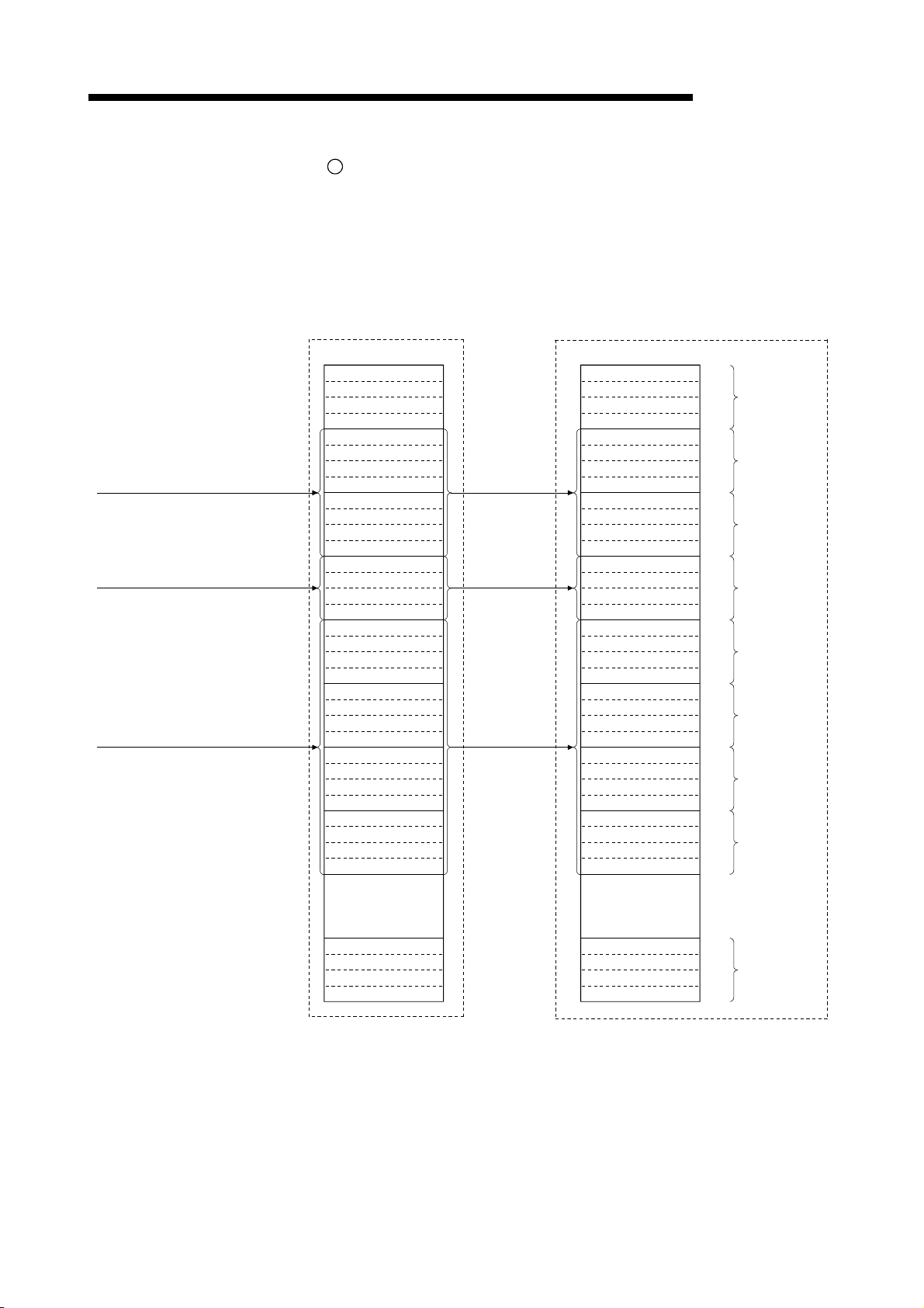
3 SPECIFICATION
MELSEC-QnA
2
Local station
• Data sent to the remote register (RWw) of remote device station can
also be received.
• Four words are used per station.
(station No.4: occupies 1 station)
Local station
RWr 0
RWr 1
RWr 2
RWr 3
RWr 4
RWr 5
RWr 6
RWr 7
RWr 8
RWr 9
RWr A
RWr B
RWr C
RWr D
RWr E
RWr F
RWr 10
RWr 11
RWr 12
RWr 13
RWr 14
RWr 15
RWr 16
RWr 17
RWr 18
RWr 19
RWr 1A
RWr 1B
RWr 1C
RWr 1D
RWr 1E
RWr 1F
to
RWr FC
RWr FD
RWr FE
RWr FF
(station No.5: occupies 4 stations)
Local station
RWr 0
RWr 1
RWr 2
RWr 3
RWr 4
RWr 5
RWr 6
RWr 7
RWr 8
RWr 9
RWr A
RWr B
RWr C
RWr D
RWr E
RWr F
RWr 10
RWr 11
RWr 12
RWr 13
RWr 14
RWr 15
RWr 16
RWr 17
RWr 18
RWr 19
RWr 1A
RWr 1B
RWr 1C
RWr 1D
RWr 1E
RWr 1F
to to
RWr FC
RWr FD
RWr FE
RWr FF
AddressRemote register (RWr) Remote register (RWr)
2E0H
2E1H
2E2H
2E3H
2E4H
2E5
2E6H
2E7
2E8H
2E9
2EA
2EBH
2EC
2EDH
2EEH
2EFH
2F0H
2F1
2F2
2F3
2F4
2F5H
2F6
2F7H
2F8
2F9H
2FAH
2FBH
2FCH
2FDH
2FEH
2FFH
300
3DBH
3DC
3DDH
3DEH
3DFH
H
H
H
H
H
H
H
H
H
H
H
H
H
For station No.1
For station No.2
For station No.3
For station No.4
For station No.5
For station No.6
For station No.7
For station No.8
For station No.64
3 - 30
Page 70

3 SPECIFICATION
MELSEC-QnA
Following tables show the relationship between station numbers and buffer memory
addresses used.
[Master station]
Station number Buffer memory address Station number Buffer memory address
1 1E0H to 1E3H 33 260H to 263H
2 1E4H to 1E7H 34 264H to 267H
3 1E8H to 1EBH 35 268H to 26BH
4 1ECH to 1EFH 36 26CH to 26FH
5 1F0H to 1F3H 37 270H to 273H
6 1F4H to 1F7H 38 274H to 277H
7 1F8H to 1FBH 39 278H to 27BH
8 1FCH to 1FFH 40 27CH to 27FH
9 200H to 203H 41 280H to 283H
10 204H to 207H 42 284H to 287H
11 208H to 20BH 43 288H to 28BH
12 20CH to 20FH 44 28CH to 28FH
13 210H to 213H 45 290H to 293H
14 214H to 217H 46 294H to 297H
15 218H to 21BH 47 298H to 29BH
16 21CH to 21FH 48 29CH to 29FH
17 220H to 223H 49 2A0H to 2A3H
18 224H to 227H 50 2A4H to 2A7H
19 228H to 22BH 51 2A8H to 2ABH
20 22CH to 22FH 52 2ACH to 2AFH
21 230H to 233H 53 2B0H to 2B3H
22 234H to 237H 54 2B4H to 2B7H
23 238H to 23BH 55 2B8H to 2BBH
24 23CH to 23FH 56 2BCH to 2BFH
25 240H to 243H 57 2C0H to 2C3H
26 244H to 247H 58 2C4H to 2C7H
27 248H to 24BH 59 2C8H to 2CBH
28 24CH to 24FH 60 2CCH to 2CFH
29 250H to 253H 61 2D0H to 2D3H
30 254H to 257H 62 2D4H to 2D7H
31 258H to 25BH 63 2D8H to 2DBH
32 25CH to 25FH 64 2DCH to 2DFH
Station number and buffer memory correspondence table
3 - 31
Page 71

3 SPECIFICATION
MELSEC-QnA
[Local station]
Station number Buffer memory address Station number Buffer memory address
1 2E0H to 2E3H 33 360H to 363H
2 2E4H to 2E7H 34 364H to 367H
3 2E8H to 2EBH 35 368H to 36BH
4 2ECH to 2EFH 36 36CH to 36FH
5 2F0H to 2F3H 37 370H to 373H
6 2F4H to 2F7H 38 374H to 377H
7 2F8H to 2FBH 39 378H to 37BH
8 2FCH to 2FFH 40 37CH to 37FH
9 300H to 303H 41 380H to 383H
10 304H to 307H 42 384H to 387H
11 308H to 30BH 43 388H to 38BH
12 30CH to 30FH 44 38CH to 38FH
13 310H to 313H 45 390H to 393H
14 314H to 317H 46 394H to 397H
15 318H to 31BH 47 398H to 39BH
16 31CH to 31FH 48 39CH to 39FH
17 320H to 323H 49 3A0H to 3A3H
18 324H to 327H 50 3A4H to 3A7H
19 328H to 32BH 51 3A8H to 3ABH
20 32CH to 32FH 52 3ACH to 3AFH
21 330H to 333H 53 3B0H to 3B3H
22 334H to 337H 54 3B4H to 3B7H
23 338H to 33BH 55 3B8H to 3BBH
24 33CH to 33FH 56 3BCH to 3BFH
25 340H to 343H 57 3C0H to 3C3H
26 344H to 347H 58 3C4H to 3C7H
27 348H to 34BH 59 3C8H to 3CBH
28 34CH to 34FH 60 3CCH to 3CFH
29 350H to 353H 61 3D0H to 3D3H
30 354H to 357H 62 3D4H to 3D7H
31 358H to 35BH 63 3D8H to 3DBH
32 35CH to 35FH 64 3DCH to 3DFH
Station number and buffer memory correspondence table
3 - 32
Page 72
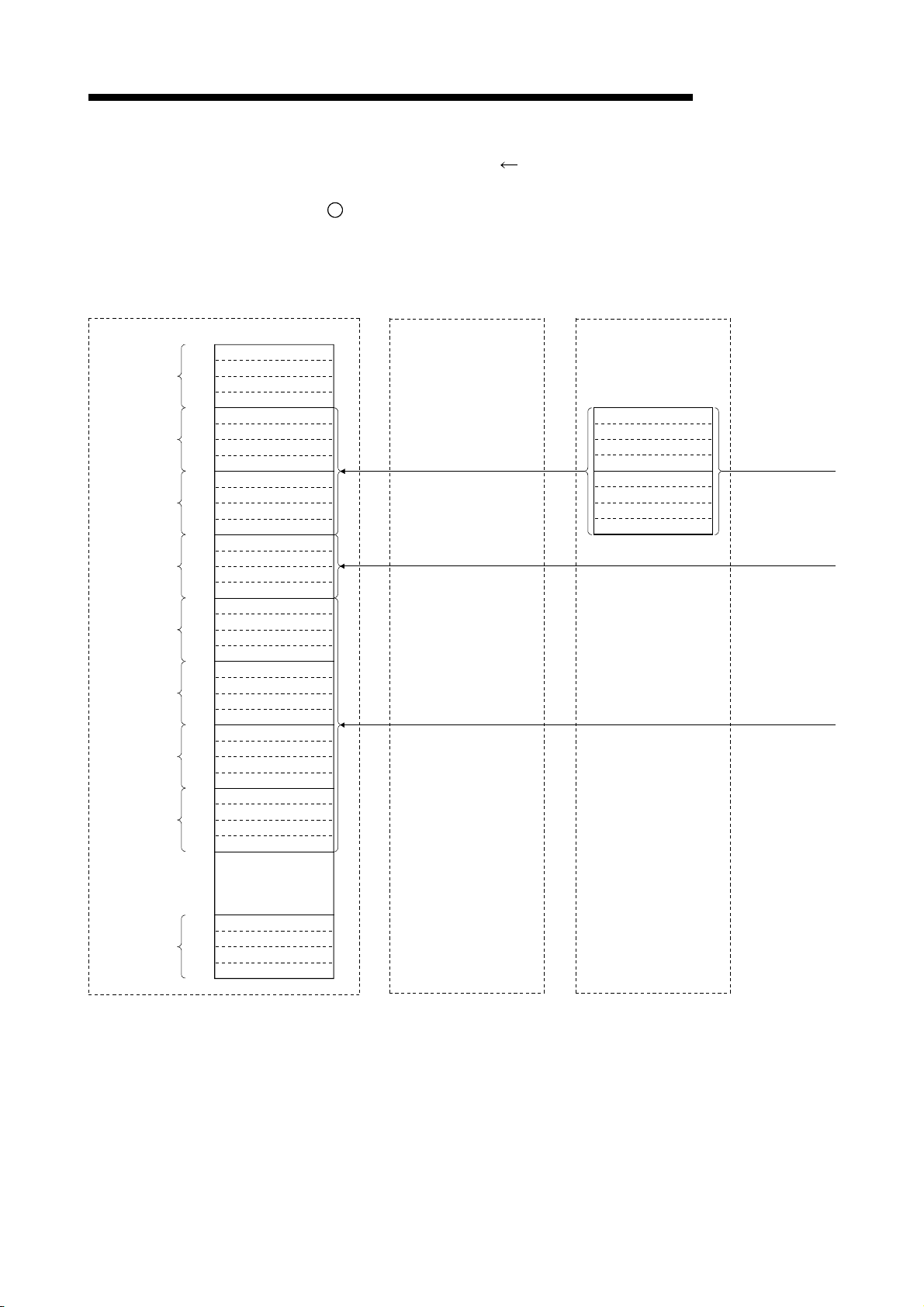
3 SPECIFICATION
Master station
Address Remote register (RWr)
H
2E0
2E1
For station No.1
For station No.2
For station No.3
For station No.4
For station No.5
For station No.6
For station No.7
For station No.8
For station No.64
2E2H
2E3H
2E4H
2E5H
2E6H
2E7
2E8H
2E9H
2EAH
2EBH
2ECH
2ED
2EEH
2EF
2F0
2F1H
2F2H
2F3
2F4
2F5
2F6
2F7H
2F8
2F9
2FAH
2FBH
2FC
2FDH
2FE
2FF
300H
to
3DBH
3DCH
3DD
3DEH
3DF
H
H
H
H
H
H
H
H
H
H
H
H
H
H
H
H
(b) Master station (RWr)
local station (RWw)
1
Master station
• Data to be sent to remote register (RWr) of remote device station and
remote register (RWw) of local station are stored.
• Four words are used per station.
(station No.1: occupies 1 station)
RWr 0
RWr 1
RWr 2
RWr 3
RWr 4
RWr 5
RWr 6
RWr 7
RWr 8
RWr 9
RWr A
RWr B
RWr C
RWr D
RWr E
RWr F
RWr 10
RWr 11
RWr 12
RWr 13
RWr 14
RWr 15
RWr 16
RWr 17
RWr 18
RWr 19
RWr 1A
RWr 1B
RWr 1C
RWr 1D
RWr 1E
RWr 1F
to
RWr FC
RWr FD
RWr FE
RWr FF
Remote I/O station
MELSEC-QnA
Remote device station (RWr)/
Remote device station
(station No.2: occupies 2 stations)
Remote register (RWr)
RWr0
RWr1
RWr2
RWr3
RWr4
RWr5
RWr6
RWr7
3 - 33
Page 73
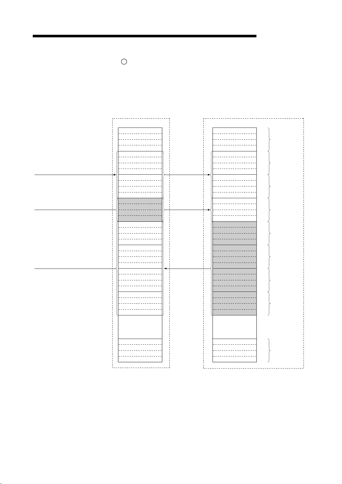
3 SPECIFICATION
MELSEC-QnA
2
Local station
• Data is sent to the master station and other local stations by storing in
the address corresponding to the host station number.
• Data in the remote register (RWr) of remote device station can also be
received.
RWw 0
RWw 1
RWw 2
RWw 3
RWw 4
RWw 5
RWw 6
RWw 7
RWw 8
RWw 9
RWw A
RWw B
RWw C
RWw D
RWw E
RWw F
RWw 10
RWw 11
RWw 12
RWw 13
RWw 14
RWw 15
RWw 16
RWw 17
RWw 18
RWw 19
RWw 1A
RWw 1B
RWw 1C
RWw 1D
RWw 1E
RWw 1F
to
RWw FC
RWw FD
RWw FE
RWw FF
Local station
1EAH
1EB
1ECH
1ED
1EE
1EF
1FAH
1FBH
1FCH
1FDH
1FEH
2DBH
2DC
2DDH
2DE
2DFH
Address
1E0
H
1E1H
1E2H
1E3H
1E4H
1E5H
1E6H
1E7H
1E8H
1E9
H
H
H
H
H
1F0
H
1F1
H
1F2
H
1F3H
1F4
H
1F5H
1F6
H
1F7H
1F8
H
1F9H
1FFH
200H
to
H
H
(station No.4: occupies 1 station)
Local station
Remote register (RWw) Remote register (RWw)
RWw 0
RWw 1
RWw 2
RWw 3
RWw 4
RWw 5
RWw 6
RWw 7
RWw 8
RWw 9
RWw A
RWw B
RWw C
RWw D
RWw E
RWw F
RWw 10
RWw 11
RWw 12
RWw 13
RWw 14
RWw 15
RWw 16
RWw 17
RWw 18
RWw 19
RWw 1A
RWw 1B
RWw 1C
RWw 1D
RWw 1E
RWw 1F
to
RWw FC
RWw FD
RWw FE
RWw FF
(station No.5: occupies 4 stations)
For station No.1
For station No.2
For station No.3
For station No.4
For station No.5
For station No.6
For station No.7
For station No.8
For station No.64
3 - 34
Page 74

3 SPECIFICATION
MELSEC-QnA
Following tables show the relationship between station numbers and buffer memory
addresses used.
[Master station]
Station
number
Buffer memory
address
1 2E0H to 2E3H 14 314H to 317H 27 348H to 34BH 40 37CH to 37FH 53 3B0H to 3B3H
2 2E4H to 2E7H 15 318H to 31BH 28 34CH to 34FH 41 380H to 383H 54 3B4H to 3B7H
3 2E8H to 2EBH 16 31CH to 31FH 29 350H to 353H 42 384H to 387H 55 3B8H to 3BBH
4 2ECH to 2EFH 17 320H to 323H 30 354H to 357H 43 388H to 38BH 56 3BCH to 3BFH
5 2F0H to 2F3H 18 324H to 327H 31 358H to 35BH 44 38CH to 38FH 57 3C0H to 3C3H
6 2F4H to 2F7H 19 328H to 32BH 32 35CH to 35FH 45 390H to 393H 58 3C4H to 3C7H
7 2F8H to 2FBH 20 32CH to 32FH 33 360H to 363H 46 394H to 397H 59 3C8H to 3CBH
8 2FCH to 2FFH 21 330H to 333H 34 364H to 367H 47 398H to 39BH 60 3CCH to 3CFH
9 300H to 303H 22 334H to 337H 35 368H to 36BH 48 39CH to 39FH 61 3D0H to 3D3H
10 304H to 307H 23 338H to 33BH 36 36CH to 36FH 49 3A0H to 3A3H 62 3D4H to 3D7H
11 308H to 30BH 24 33CH to 33FH 37 370H to 373H 50 3A4H to 3A7H 63 3D8H to 3DBH
12 30CH to 30FH 25 340H to 343H 38 374H to 377H 51 3A8H to 3ABH 64 3DCH to 3DFH
13 310H to 313H 26 344H to 347H 39 378H to 37BH 52 3ACH to 3AFH – –
Station number and buffer memory correspondence table
Station
number
Buffer memory
address
Station
number
Buffer memory
address
Station
number
Buffer memory
address
Station
number
Buffer memory
address
[Local station]
Station
number
Buffer memory
address
1 1E0H to 1E3H 14 214H to 217H 27 248H to 24BH 40 27CH to 27FH 53 2B0H to 2B3H
2 1E4H to 1E7H 15 218H to 21BH 28 24CH to 24FH 41 280H to 283H 54 2B4H to 2B7H
3 1E8H to 1EBH 16 21CH to 21FH 29 250H to 253H 42 284H to 287H 55 2B8H to 2BBH
4 1ECH to 1EFH 17 220H to 223H 30 254H to 257H 43 288H to 28BH 56 2BCH to 2BFH
5 1F0H to 1F3H 18 224H to 227H 31 258H to 25BH 44 28CH to 28FH 57 2C0H to 2C3H
6 1F4H to 1F7H 19 228H to 22BH 32 25CH to 25FH 45 290H to 293H 58 2C4H to 2C7H
7 1F8H to 1FBH 20 22CH to 22FH 33 260H to 263H 46 294H to 297H 59 2C8H to 2CBH
8 1FCH to 1FFH 21 230H to 233H 34 264H to 267H 47 298H to 29BH 60 2CCH to 2CFH
9 200H to 203H 22 234H to 237H 35 268H to 26BH 48 29CH to 29FH 61 2D0H to 2D3H
10 204H to 207H 23 238H to 23BH 36 26CH to 26FH 49 2A0H to 2A3H 62 2D4H to 2D7H
11 208H to 20BH 24 23CH to 23FH 37 270H to 273H 50 2A4H to 2A7H 63 2D8H to 2DBH
12 20CH to 20FH 25 240H to 243H 38 274H to 277H 51 2A8H to 2ABH 64 2DCH to 2DFH
13 210H to 213H 26 244H to 247H 39 278H to 27BH 52 2ACH to 2AFH – –
Station number and buffer memory correspondence table
Station
number
Buffer memory
address
Station
number
Buffer memory
address
Station
number
Buffer memory
address
Station
number
Buffer memory
address
3 - 35
Page 75

3 SPECIFICATION
MELSEC-QnA
(4) Link special relay (SB)
Data link status is stored in the form of bit on/off information.
Buffer memory address 5E0
H to 5FFH corresponds to SB0000 to SB01FF.
Refer to Section 8.4.1 for details of link special relay (SB0000 to SB01FF).
Following table shows the relationship between buffer memory address 5E0
5FF
Address b15 b14 b13 b12 b11 b10 b9 b8 b7 b6 b5 b4 b3 b2 b1 b0
H
5E0
5E1H
5E2H
5E3H
5E4H
5E5H
5E6H
5E7H
5E8H
5E9H
5EAH
5EBH
5ECH
5EDH
5EEH
5EFH
5F0H
5F1H
5F2H
5F3H
5F4H
5F5H
5F6H
5F7H
5F8H
5F9H
5FAH
5FBH
5FCH
5FDH
5FEH
5FFH
F E D C B A 9 8 7 6 5 4 3 2 1 0
1F 1E 1D 1C 1B 1A 19 18 17 16 15 14 13 12 11 10
2F 2E 2D 2C 2B 2A 29 28 27 26 25 24 23 22 21 20
3F 3E 3D 3C 3B 3A 39 38 37 36 35 34 33 32 31 30
4F 4E 4D 4C 4B 4A 49 48 47 46 45 44 43 42 41 40
5F 5E 5D 5C 5B 5A 59 58 57 56 55 54 53 52 51 50
6F 6E 6D 6C 6B 6A 69 68 67 66 65 64 63 62 61 60
7F 7E 7D 7C 7B 7A 79 78 77 76 75 74 73 72 71 70
8F 8E 8D 8C 8B 8A 89 88 87 86 85 84 83 82 81 80
9F 9E 9D 9C 9B 9A 99 98 97 96 95 94 93 92 91 90
AF AE AD 9AC AB AA A9 A8 A7 A6 A5 A4 A3 A2 A1 A0
BF BE BD BC BB BA B9 B8 B7 B6 B5 B4 B3 B2 B1 B0
CF CE CD CC CB CA C9 C8 C7 C6 C5 C4 C3 C2 C1 C0
DF DE DD DC DB DA D9 D8 D7 D6 D5 D4 D3 D2 D1 D0
EF EE ED EC EB EA E9 E8 E7 E6 E5 E4 E3 E2 E1 E0
FF FE FD FC FB FA F9 F8 F7 F6 F5 F4 F3 F2 F1 F0
10F 10E 10D 10C 10B 10A 109 108 107 106 105 104 103 102 101 100
11F 11E 11D 11C 11B 11A 119 118 117 116 115 114 113 112 111 110
12F 12E 12D 12C 12B 12A 129 128 127 126 125 124 123 122 121 120
13F 13E 13D 13C 13B 13A 139 138 137 136 135 134 133 132 131 130
14F 14E 14D 14C 14B 14A 149 148 147 146 145 144 143 142 141 140
15F 15E 15D 15C 15B 15A 159 158 157 156 155 154 153 152 151 150
16F 16E 16D 16C 16B 16A 169 168 167 166 165 164 163 162 161 160
17F 17E 17D 17C 17B 17A 179 178 177 176 175 174 173 172 171 170
18F 18E 18D 18C 18B 18A 189 188 187 186 185 184 183 182 181 180
19F 19E 19D 19C 19B 19A 199 198 197 196 195 194 193 192 191 190
1AF 1AE 1AD 1AC 1AB 1AA 1A9 1A8 1A7 1A6 1A5 1A4 1A3 1A2 1A1 1A0
1BF 1BE 1BD 1BC 1BB 1BA 1B9 1B8 1B7 1B6 1B5 1B4 1B3 1B2 1B1 1B0
1CF 1CE 1CD 1CC 1CB 1CA 1C9 1C8 1C7 1C6 1C5 1C4 1C3 1C2 1C1 1C0
1DF 1DE 1DD 1DC 1DB 1DA 1D9 1D8 1D7 1D6 1D5 1D4 1D3 1D2 1D1 1D0
1EF 1EE 1ED 1EC 1EB 1EA 1E9 1E8 1E7 1E6 1E5 1E4 1E3 1E2 1E1 1E0
1FF 1FE 1FD 1FC 1FB 1FA 1F9 1F8 1F7 1F6 1F5 1F4 1F3 1F2 1F1 1F0
H and SB0000 to SB01FF.
(5) Link special register (SW)
Data link status is stored in the form of word information.
Buffer memory address 600
Refer to Section 8.4.2 for details of link special register (SW0000 to 01FF).
H to 7FFH corresponds to SW0000 to SW01FF.
H to
3 - 36
Page 76

3 SPECIFICATION
MEMO
MELSEC-QnA
3 - 37
Page 77

4 FUNCTIONS
4. FUNCTIONS
MELSEC-QnA
This chapter describes the functions.
4.1 Function List
The function list is shown in Table 4.1.
Item Function summary Reference
Communication between master and
remote I/O stations
Communication between master and
remote device stations
Communication between master and local
stations
Communication with compound system
Reserved station function
Error invalid station function
Data-link status setting when a master
station programmable controller CPU error
occurs
Parameter registration to E2PROM
Input data from a data-link faulty station
status setting
Module reset function from a sequence
program
Data link stop/restart
Automatic return function
Slave station cutoff function
Data link status check
(SB/SW)
RAS function
Offline test
Online test*
Monitor/diagnosis
Table 4.1 Function list
Performs on/off data communication with remote I/O station. Section 4.2
Performs on/off data and numeric data communication with
remote device station.
Performs on/off data and numeric data communication with
local station.
Performs communication with remote I/O, remote device and
local stations.
By setting the remote and local stations planned to be
connected in the future as reserved stations, these stations will
not be treated as error. When specified to an already connected
module, data link cannot be performed at all.
Remote and local stations that can no longer perform data link
due to power off, etc., will not be treated as data-link faulty
stations.
Data-link status can be set when an operation-stop error occurs
with the master station programmable controller CPU.
By registering the parameters in the master module's E
the parameters do not have to be written every time the master
module is started up.
The status (clear/store) of the input (received) data from the
data-link faulty station caused by power off, etc. can be set.
When the switch setting is changed or an error occurred with
the module, the module can be reset from the sequence
program instead of resetting the programmable controller CPU.
When executing the data link from Yn6 or Yn8, the data link can
be stopped or restarted.
When the module removed from the data link due to power off,
etc. recovers to normal status, the module automatically joins
the data link.
The module which no longer can continue the data link due to
power off, etc. is removed from the data link, and the data link is
continued with only the normal modules.
The data link status can be checked. Can be used for sequence
program interlocking, etc.
The following tests can be conducted:
• Hardware test........................... Operation check for the
individual module
• Line test....................................Module connection condition
check
• Parameter verification test........ Verify the set parameter
contents
Line tests and link control, such as start and stop are available
from peripheral devices.
Monitoring and diagnosing are available from peripheral
devices.
2
PROM,
Section 4.3
Section 4.4
Section 4.5
Section 4.6
Section 4.7
Section 4.8
Section 6.1
Section 4.9
Section 4.10
Section 4.11
Section
4.12.1
Section
4.12.2
Section 8.3
Section 7.4
Section 7.7
Section 7.8
Section
15.10
Section
15.11
Function
availability
Master
station
Local
station
4
4 - 1
Page 78

4 FUNCTIONS
MELSEC-QnA
The functions indicated with * are available only when the CPU and software package
versions are any of the following:
• Q2ASCPU(S1) of the software version Q or later
• Q2ASHCPU(S1) of the software version Q or later
• Q2ACPU(S1) of the software version E or later
• Q3ACPU of the software version E or later
• Q4ACPU of the software version E or later
• SW21VD-GPPQ/SW2NX-GPPQ or later
4 - 2
Page 79

4 FUNCTIONS
4.2 Communication Between the Master Station and Remote I/O Station
The overview of the communication between the master station and remote I/O station
Programmable controller CPU
is described.
Master station
MELSEC-QnA
Remote I/O station
SET Yn0
1
2
SET Yn8
4
FROM
5
TO
Refresh instruction
Data link startup
2
by E
PROM
parameters
Buffer memory
Remote input
(RX)
Remote output
(RY)
3
Link scan
6
Link scan
Input
Output
[Data link startup]
1
Turn on the refresh instruction (Yn0) and make the remote output (RY) data valid.
When the refresh instruction (Yn0) is off, all the remote output (RY) data is treated
as 0 (off).
2
Turn on the data link startup by the E2PROM parameters (Yn8), and start the data
link.
2
However, the parameters must be set in E
PROM beforehand.
When the data link is started normally, the host data link status (Xn1) turns on.
POINT
The data link can be started from the parameters written in the "parameter information area" in
the buffer memory. (Refer to Chapter 6.)
4 - 3
Page 80
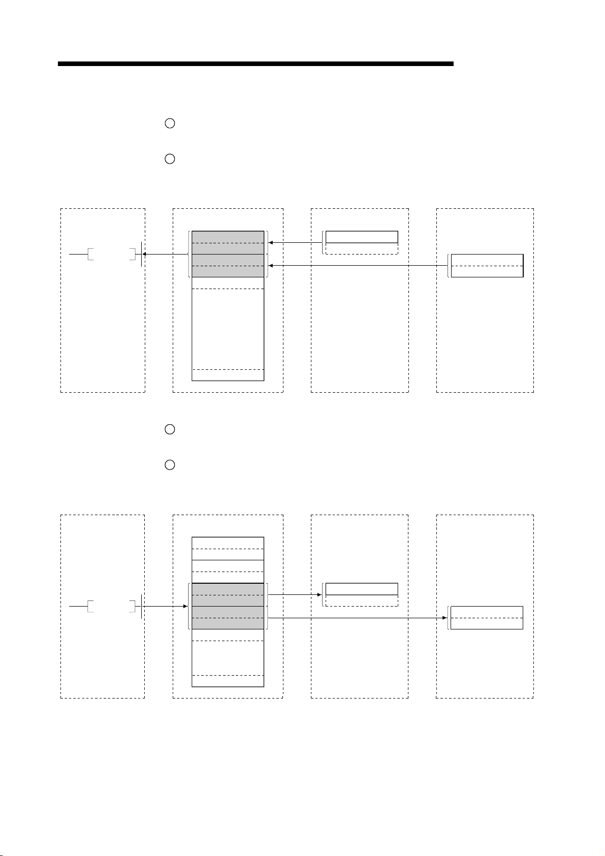
4 FUNCTIONS
Programmable controller
CPU
FROM
MELSEC-QnA
[Remote input]
3
The remote I/O station's input status is automatically (for each link scan) stored in
the master station's "remote input (RX)" in the buffer memory.
4
The input status stored in the "remote input (RX)" in the buffer memory is received
to the programmable controller CPU with the FROM instruction.
Master station
Remote input (RX)
RX0F
to
RX00
toRX1F RX10
RX2F
RX3F RX30
RX4F RX40
RX20to
to
to
to
Remote I/O station
(station No. 1: occupies 1 station)
toX0F
X00
Remote I/O station
(station No. 2: occupies 1 station)
to
X0F X00
toX1F
X10
Programmable controller
CPU
TO
RX7FF RX7F0to
32 points module16 points module
[Remote output]
5
With the TO instruction, the on/off data output from the remote I/O station is written
to the "remote output (RY)" in the buffer memory.
6
The output status stored in the "remote output (RY)" in the buffer memory is
automatically output (for each link scan) from the remote I/O station.
Master station
Remote input (RY)
toRY0F RY00
toRY1F RY10
RY2F
to
RY20
to
RY3F RY30
RY4F
to
RY40
RY5F
to
RY50
RY6F
to
RY60
RY7F
to
RY70
to
RY8F RY80
to
Remote I/O station
(station No. 3: occupies 1 station)
to
Y0F Y00
Remote I/O station
(station No. 4: occupies 1 station)
toY0F Y00
toY1F
Y10
RY7FF
RY7F0to
16 points module 32 points module
4 - 4
Page 81

4 FUNCTIONS
MELSEC-QnA
4.3 Communication Between the Master Station and Remote Device Station
The overview of the communication between the master station and remote device
Programmable controller CPU Master station
station is described.
Remote device station
FROM
TO
SET Yn0
SET Yn8
1
2
4
5
Refresh instruction
Data link startup
by EEPROM
parameters
Buffer memory
Remote input
(RX)
Remote output
(RY)
3
Link scan
6
Link scan
Remote input
(RX)
Remote output
(RY)
TO
FROM
7
10
Remote register
(RWw)
Remote register
(RWr)
8
Link scan
9
Link scan
Remote register
(RWw)
Remote register
(RWr)
4 - 5
Page 82
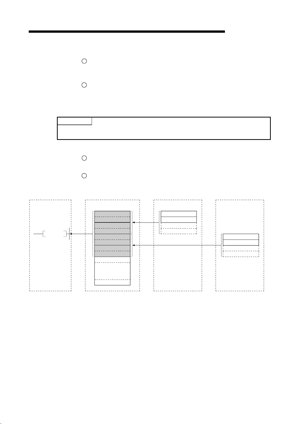
4 FUNCTIONS
POINT
The data link can be started from the parameters written in the "parameter information area" in
the buffer memory. (Refer to Chapter 6.)
Programmable controller
CPU
MELSEC-QnA
[Data link startup]
1
Turn on the refresh instruction (Yn0) and make the remote output (RY) data valid.
When the refresh instruction (Yn0) is off, all the remote output (RY) data is treated
as 0 (off).
2
Turn on the data link startup by the E2PROM parameters (Yn8), and start the data
link.
2
However, the parameters must be set in E
PROM beforehand.
When the data link is started normally, the host data link status (Xn1) turns on.
[Remote input]
3
The remote device station's remote input (RX) is automatically (for each link scan)
stored in the master station's "remote input (RX)" in the buffer memory.
4
The input status stored in the "remote input (RX)" in the buffer memory is received
to the programmable controller CPU with the FROM instruction.
Master station
Remote device station
(station No. 1: occupies 2 stations)
Remote device station
(station No. 3: occupies 2 stations)
FROM
Remote input (RX)
toRX0F RX00
toRX1F
RX10
RX2F RX20to
RX3F
to
RX30
RX4F RX40to
RX5F RX50to
RX6F RX60to
RX7F RX70to
RX8F RX80to
to
RX7FF
to
RX7F0
Remote input (RX)
toRX0F
RX00
RX1F
to
RX10
Remote input (RX)
RX0F
RX1F
RX00to
RX10to
4 - 6
Page 83
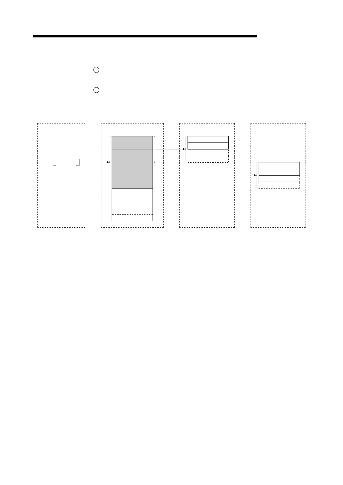
4 FUNCTIONS
Programmable controller
CPU Master station
MELSEC-QnA
[Remote output]
5
With the TO instruction, the on/off data in the remote device station's remote output
(RY) is written to the "remote output (RY)" in the buffer memory.
6
Depending on the output status stored in the "remote output (RY)" in the buffer
memory, the remote device station's remote output (RY) is turned on/off.
Remote device station
(station No. 1:
occupies 2 stations)
Remote device station
(station No. 3:
occupies 2 stations)
TO
Remote output (RY)
RY0F to RY00
RY1F to RY10
RY2F to RY20
RY3F to RY30
RY4F to RY40
RY5F to RY50
RY6F to RY60
RY7F to RY70
RY8F to RY80
to
RY7FF to RY7F0
Remote output (RY)
RY0F to RY00
RY1F to RY10
Remote output (RY)
RY0F to RY00
RY1F to RY10
4 - 7
Page 84
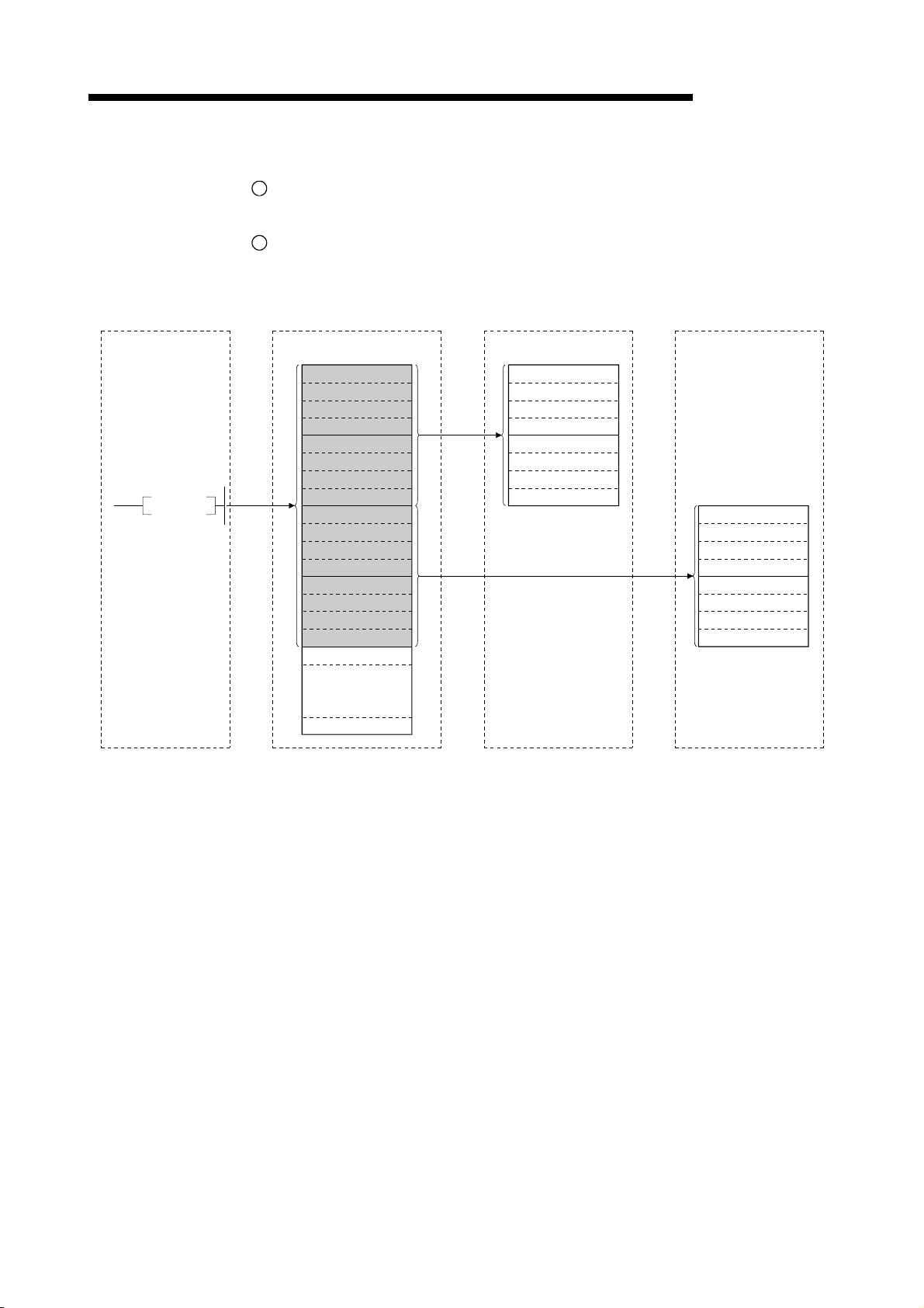
4 FUNCTIONS
Programmable controller
CPU
MELSEC-QnA
[Written to the remote register (RWw)]
7
With the TO instruction, the transmission data is written to the "remote register
(RWw)" in the buffer memory.
8
The data stored in the "remote register (RWw)" in the buffer memory is sent to the
remote device station's remote register (RWw).
Master station
Remote device station
(station No. 1:
occupies 2 stations)
Remote device station
(station No. 3:
occupies 2 stations)
TO
Remote register (RWw)
RWw0
RWw1
RWw2
RWw3
RWw4
RWw5
RWw6
RWw7
RWw8
RWw9
RWwA
RWwB
RWwC
RWwD
RWwE
RWwF
RWw10
to
RWwFF
Remote register (RWw)
RWw0
RWw1
RWw2
RWw3
RWw4
RWw5
RWw6
RWw7
Remote register (RWw)
RWw0
RWw1
RWw2
RWw3
RWw4
RWw5
RWw6
RWw7
4 - 8
Page 85
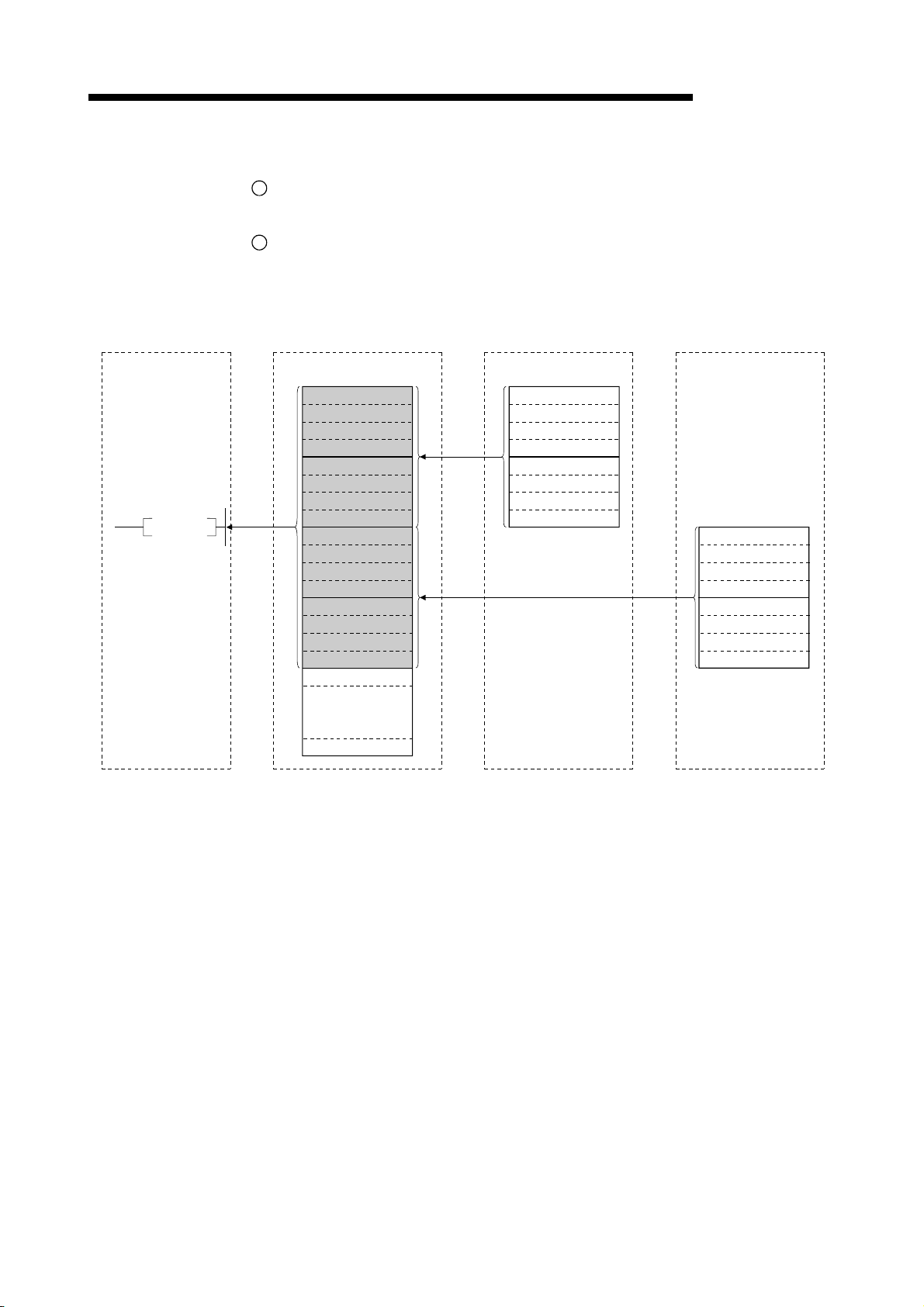
4 FUNCTIONS
Programmable controller
CPU
MELSEC-QnA
[Reading from the remote register (RWr)]
9
The data in the remote device station's remote register (RWr) is automatically
stored in the master station's "remote register (RWr)" in the buffer memory
10
The remote device station's remote register (RWr) data stored in the "remote
register (RWr)" in the buffer memory is received to the programmable controller
CPU with the FROM instruction.
Remote device station
(station No. 3:
occupies 2 stations)
Master station
Remote device station
(station No. 1:
occupies 2 stations)
FROM
Remote register (RWr)
RWr0
RWr1
RWr2
RWr3
RWr4
RWr5
RWr6
RWr7
RWr8
RWr9
RWrA
RWrB
RWrC
RWrD
RWrE
RWrF
RWr10
to
RWrFF
Remote register (RWr)
RWr0
RWr1
RWr2
RWr3
RWr4
RWr5
RWr6
RWr7
Remote register (RWr)
RWr0
RWr1
RWr2
RWr3
RWr4
RWr5
RWr6
RWr7
4 - 9
Page 86
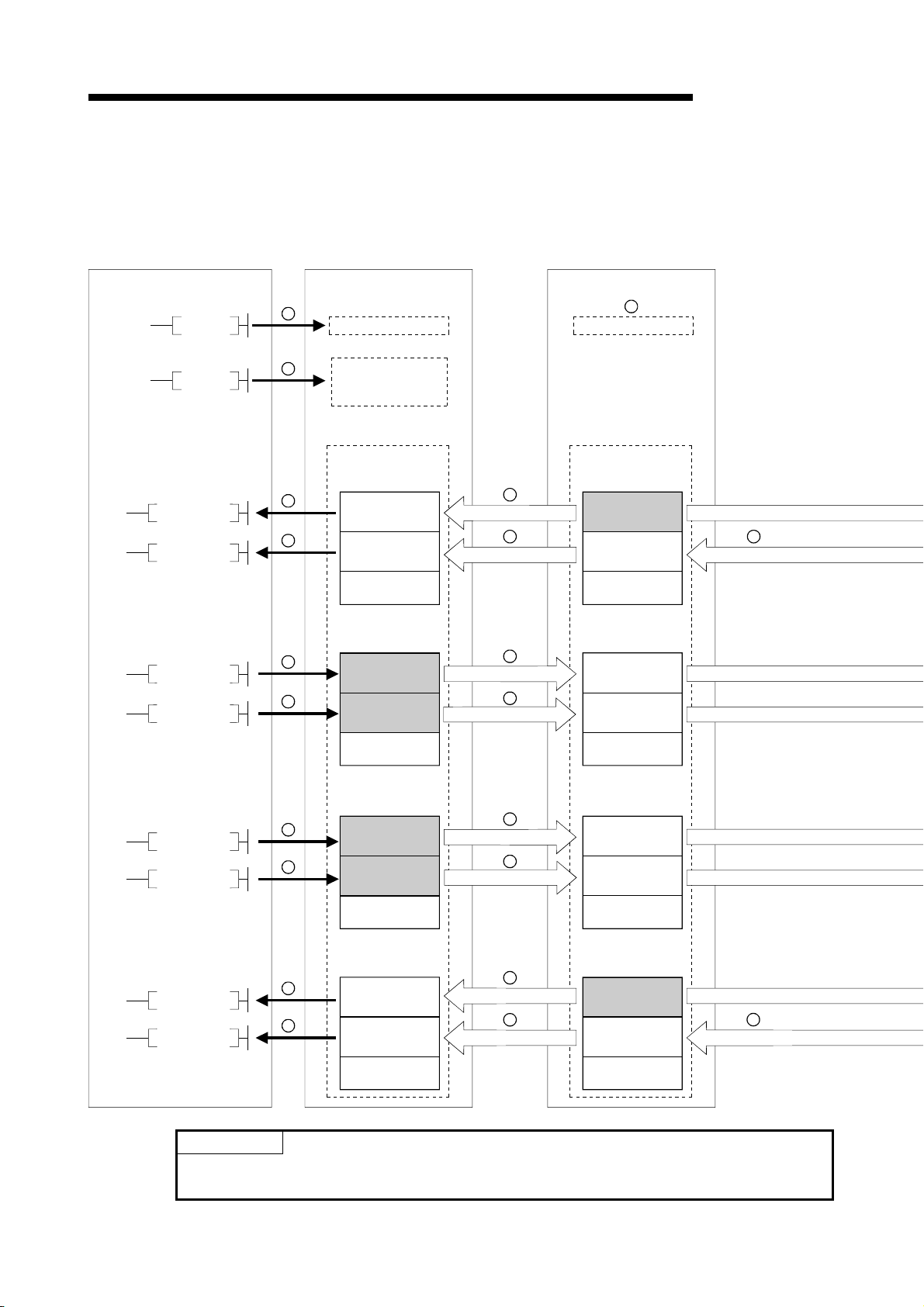
4 FUNCTIONS
4.4 Communication Between the Master Station and Local Station
The overview of the communication between the master and local stations is
described.
Master stationProgrammable controller CPU
Local station (station No. 1)
MELSEC-QnA
SET Yn0
SET Yn8
FROM
FROM
TO
TO
1
2
5
5
7
7
Refresh instruction
Data link startup
by EEPROM
parameters
Buffer memory
Remote input (RX)
Receive area from
local station No. 1
Receive area from
local station No. 2
to
Remote output (RY)
Send area to
local station No. 1
Send area to
local station No. 2
to
4
Link scan
4 4
Link scan
8
Link scan
8
Link scan
Refresh instruction
Remote output (RY)
Remote input (RX)
1
Buffer memory
Host (station No. 1)
send area
Receive area from
local station No. 2
to
Receive area from
master station
Receive area from
master station
to
Link scan
Link scan
Link scan
Link scan
TO
TO
FROM
FROM
Remote register
(RWw)
10
10
15
15
Send area to
local station No. 1
Send area to
local station No. 2
to
Remote register
(RWr)
Receive area from
local station No. 1
Receive area from
local station No. 2
to
11
Link scan
11
Link scan
14
Link scan
14
Link scan
Remote register
(RWr)
Receive area from
master station
Receive area from
master station
to
Remote register
(RWw)
Host (station No. 1)
send area
Receive area from
local station No. 2
to
POINT
The master station sends only the data for the stations that have started the data link.
The data for the stations that have not started the data link are not sent.
4 - 10
Link scan
Link scan
Link scan
14
Link scan
Page 87
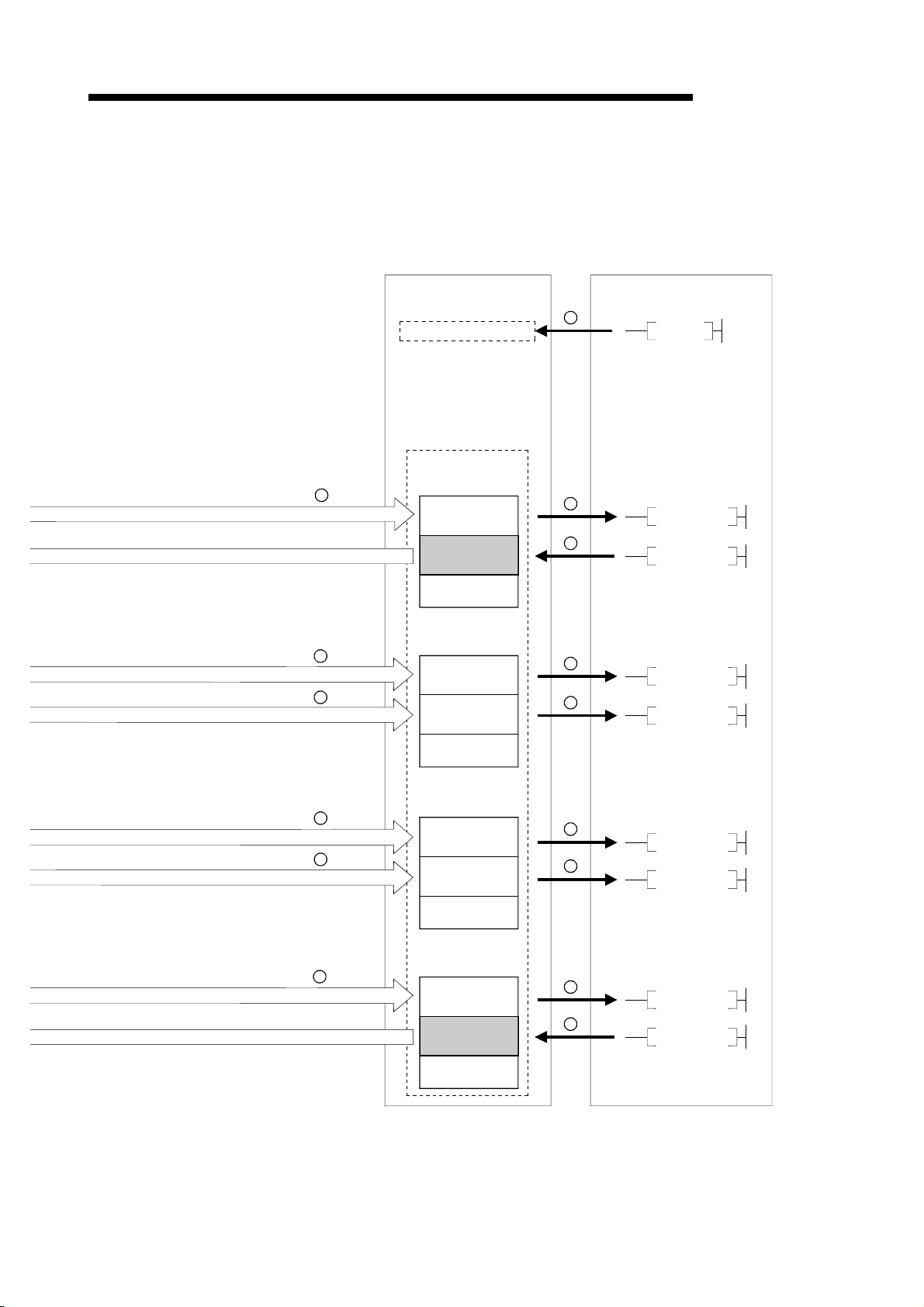
4 FUNCTIONS
MELSEC-QnA
Local station (station No. 2)
Programmable controller CPU
4
Link scan
Link scan
8
Link scan
8
Link scan
Refresh instruction
Buffer memory
Remote output (RY)
Receive area
from local
station No. 1
Send area
for host
(station No. 2)
to
Remote input (RX)
Receive area
from master
station
Receive area
from master
station
to
1
SET Yn0
6
FROM
3
TO
9
FROM
9
FROM
11
Link scan
11
Link scan
14
Link scan
Link scan
Remote register
(RWr)
Receive area
from master
station
Receive area
from master
station
to
Remote register
(RWw)
Receive area
from local
station No. 1
Send area
for host
(station No. 2)
to
4 - 11
12
FROM
12
FROM
16
FROM
13
TO
Page 88
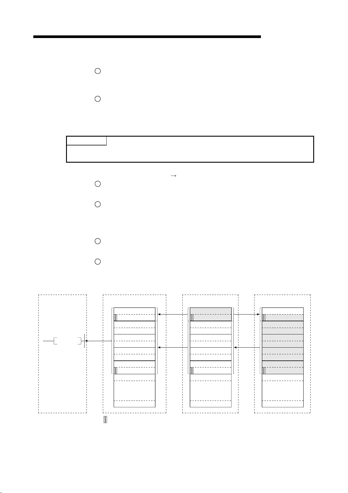
4 FUNCTIONS
POINT
The data link can also be started from the parameters written in the "parameter data area" in
the buffer memory. (Refer to chapter 6.)
Programmable controller
CPU
MELSEC-QnA
[Data link startup]
1
Turn on the refresh instruction (Yn0) and make the remote output (RY) data valid.
When the refresh instruction (Yn0) is off, all the remote output (RY) data is treated
as 0 (off).
2
Turn on the data link startup by the E2PROM parameters (Yn8) and start the data
link.
2
However, the parameters must be set in the E
PROM beforehand.
When the data link is started normally, the host data link status (Xn1) turns on.
[On/off data from local station
3
With the TO instruction, write the on/off data to be sent to the master and other local
master and other local stations]
stations to the local station's "remote output (RY)" in the buffer memory.
4
The data in local station's "remote output (RY)" in the buffer memory is
automatically (for each link scan) stored in the master station's "remote input (RX)"
in the buffer memory and other local station's "remote output (RY)" in the buffer
memory.
5
The input status stored in the "remote input (RX)" in the buffer memory is received
to the programmable controller CPU with the FROM instruction.
6
The input status stored in the "remote output (RY)" in the buffer memory is received
to the programmable controller CPU with the FROM instruction.
Master station
Local station
(station No. 1:
occupies 1 station)
Local station
(station No. 2:
occupies 4 stations)
FROM
Remote input (RX) Remote output (RY)
RX0F to RX00
RX1D to RX10
RX2F to RX20
RX3F to RX30
RX4F to RX40
RX5F to RX50
RX6F to RX60
RX7F to RX70
RX8F to RX80
RX9D to RX90
RXAF to RXA0
to
RX7FF to RX7F0
...The last 2 bits cannot be used when the master station and the local station are communicating.
RY0F to RY00
RY1D to RY10
RY2F to RY20
RY3F to RY30
RY4F to RY40
RY5F to RY50
RY6F to RY60
RY7F to RY70
RY8F to RY80
RY9D to RY90
RYAF to RYA0
to
RY7FF to RY7F0
Remote output (RY)
RY0F to RY00
RY1D to RY10
RY2F to RY20
RY3F to RY30
RY4F to RY40
RY5F to RY50
RY6F to RY60
RY7F to RY70
RY8F to RY80
RY9D to RY90
RYAF to RYA0
to
RY7FF to RY7F0
4 - 12
Page 89

4 FUNCTIONS
Programmable controller
CPU
TO
MELSEC-QnA
[On/off data from the master station
7
With the TO instruction, the on/off data to be sent to the local station is written to the
the local station]
master station's "remote output (RY)" in the buffer memory.
8
The data in the "remote output (RY)" in the buffer memory is automatically (for each
link scan) stored in the local station's remote input (RX) in the buffer memory.
9
The input status stored in the "remote input (RX)" in the buffer memory is received
to the programmable controller CPU with the FROM instruction.
Local station
Master station
Remote output (RY) Remote input (RX) Remote input (RX)
RY0F to RY00
RY1D to RY10
RY2F to RY20
RY3F to RY30
RY4F to RY40
RY5F to RY50
RY6F to RY60
RY7F to RY70
RY8F to RY80
RY9D to RY90
RYAF to RYA0
(station No. 1:
occupies 1 station)
RX0F to RX00
RX1D to RX10
RX2F to RX20
RX3F to RX30
RX4F to RX40
RX5F to RX50
RX6F to RX60
RX7F to RX70
RX8F to RX80
RX9D to RX90
RXAF to RXA0
Local station
(station No. 2:
occupies 4 stations)
RX0F to RX00
RX1D to RX10
RX2F to RX20
RX3F to RX30
RX4F to RX40
RX5F to RX50
RX6F to RX60
RX7F to RX70
RX8F to RX80
RX9D to RX90
RXAF to RXA0
to
RY7FF to RY7F0
...The last 2 bits cannot be used when the master station and the local station are communicating.
to
RX7FF to RX7F0
to
RX7FF to RX7F0
4 - 13
Page 90

r
4 FUNCTIONS
Programmable controlle
CPU
TO
MELSEC-QnA
[Word data from the master station to all local stations]
10
With the TO instruction, the word data to be sent to all local station is written to the
master station's "remote register (RWw)" in the buffer memory.
11
The data in the "remote register (RWw)" in the buffer memory is automatically (for
each link scan) stored to all local station's "remote registers (RWr)".
12
The word data stored in the "remote register (RWr)" in the buffer memory is
received to the programmable controller CPU with the FROM instruction.
Local station
(station No. 1:
Master station
Remote register (RWw) Remote register (RWr) Remote register (RWr)
RWw0
RWw1
RWw2
RWw3
RWw4
RWw5
RWw6
RWw7
RWw8
RWw9
RWwA
RWwB
RWwC
RWwD
RWwE
RWwF
RWw10
RWw11
RWw12
RWw13
RWw14
occupies 1 station)
RWr0
RWr1
RWr2
RWr3
RWr4
RWr5
RWr6
RWr7
RWr8
RWr9
RWrA
RWrB
RWrC
RWrD
RWrE
RWrF
RWr10
RWr11
RWr12
RWr13
RWr14
Local station
(station No. 2:
occupies 4 stations)
RWr0
RWr1
RWr2
RWr3
RWr4
RWr5
RWr6
RWr7
RWr8
RWr9
RWrA
RWrB
RWrC
RWrD
RWrE
RWrF
RWr10
RWr11
RWr12
RWr13
RWr14
to
RWwFF
4 - 14
to
RWrFF
to
RWrFF
Page 91

4 FUNCTIONS
Programmable controller
CPU
MELSEC-QnA
[Word data from the local station
13
With the TO instruction, the word data to be sent to the master station or other local
the master station/other local stations]
stations is written to the local station's "remote register (RWw)" in the buffer
memory.
However, only writing can be performed to the area corresponding to the host
station number.
14
The data in the "remote register (RWw)" in the buffer memory is automatically (for
each link scan) stored in the master station's "remote register (RWr)" and other local
station's "remote register (RWw)".
15
The word data stored in the "remote register (RWr)" in the buffer memory is
received to the programmable controller CPU with the FROM instruction.
16
The word data stored in the "remote register (RWw)" in the buffer memory is
received to the programmable controller CPU with the FROM instruction.
Master station
Local station
(station No. 1:
occupies 1 station)
Local station
(station No. 2:
occupies 4 stations)
FROM
Remote register (RWr) Remote register (RWw) Remote register (RWw)
RWr0
RWr1
RWr2
RWr3
RWr4
RWr5
RWr6
RWr7
RWr8
RWr9
RWrA
RWrB
RWrC
RWrD
RWrE
RWrF
RWr10
RWr11
RWr12
RWr13
RWr14
to
RWrFF
RWw0
RWw1
RWw2
RWw3
RWw4
RWw5
RWw6
RWw7
RWw8
RWw9
RWwA
RWwB
RWwC
RWwD
RWwE
RWwF
RWw10
RWw11
RWw12
RWw13
RWw14
to
RWwFF
RWw0
RWw1
RWw2
RWw3
RWw4
RWw5
RWw6
RWw7
RWw8
RWw9
RWwA
RWwB
RWwC
RWwD
RWwE
RWwF
RWw10
RWw11
RWw12
RWw13
RWw14
to
RWwFF
4 - 15
Page 92

4 FUNCTIONS
4.5 Communication in Compound Systems
The overview of the communication where the remote I/O station, remote device
Programmable controller CPU
station and local station coexist in the system.
Master station
MELSEC-QnA
Remote I/O station (station No. 1)
FROM
FROM
FROM
FROM
TO
TO
TO
TO
SET Yn0
SET Yn8
1
2
Refresh instruction
Data link startup
by EEPROM
parameters
Buffer memory
5
5
5
5
Remote input (RX)
Receive area
from remote
I/O station No. 1
Receive area
from remote
device station No. 2
Receive area from
local station No. 3
Receive area from
local station No. 4
Remote output (RY)
6
6
6
6
Send area to remote
I/O station No. 1
Send area to remote
device station No. 2
Send area to
local station No. 3
Send area to
local station No. 4
3
Input
3
3
3
7
Output
TO
TO
TO
FROM
FROM
FROM
Remote register
(RWw)
Unusable
8
8
8
(station No. 1)
Send area to remote
device station No. 2
Send area to
local station No. 3
Send area to
local station No. 4
Remote register
(RWr)
Unusable
13
13
13
(station No. 1)
Receive area
from remote
device station No. 2
Receive area from
local station No. 3
Receive area from
local station No. 4
11
12
12
4 - 16
Page 93

4 FUNCTIONS
Remote device station (station No. 2)
Local station (station No. 3)
MELSEC-QnA
Local station (station No. 4)
1
Refresh instruction
Buffer memory
Remote output (RY)
Remote input (RX)
3
3
Receive area
from remote I/O
station No. 1
Receive area
from remote device
station No . 2
Host (station No. 3)
send area
Receive area from
local station No. 4
3
3
4
4
Remote output (RY)
Remote input (RX)
7
7
Remote output (RY)
7
7
7
Receive area from
master station
(station No. 1)
Receive area from
master station
(station No. 2)
Receive area from
master station
(station No. 3)
Receive area from
master station
(station No. 4)
7
7
7
7
Remote register
(RWr)
Unusable
9
Remote register
(RWw)
10
9
9
(station No. 1)
Receive area from
master station
Receive area from
master station
Receive area from
master station
10
9
9
Remote register
(RWw)
Unusable
Remote register
(RWr)
11
(station No. 1)
Receive area
from remote device
station No . 2
Host (station No. 3)
send area
Receive area from
local station No. 4
11
12
12
1
Refresh instruction
Buffer memory
Receive area
from remote I/O
station No. 1
Receive area
from remote device
station No. 2
Receive area from
local station No. 3
Host (station No. 4)
send area
Remote input (RX)
Receive area from
master station
(station No. 1)
Receive area from
master station
(station No. 2)
Receive area from
master station
(station No. 3)
Receive area from
master station
(station No. 4)
Remote register
(RWr)
Unusable
(station No. 1)
Receive area from
master station
Receive area from
master station
Receive area from
master station
Remote register
(RWw)
Unusable
(station No. 1)
Receive area
from remote device
station No. 2
Receive area from
local station No. 3
Host (station No. 4)
send area
4 - 17
Page 94

4 FUNCTIONS
POINT
The data link can also be started from the parameters written in the "parameter data area" in
the buffer memory. (Refer to chapter 6.)
Master station
MELSEC-QnA
[Data link startup]
1
Turn on the refresh instruction (Yn0) and make the remote output (RY) data valid.
When the refresh instruction (Yn0) is off, all the remote output (RY) data is treated
as 0 (off).
2
Turn on the data link startup by the E2PROM parameters (Yn8) and start the data
link.
2
However, the parameters must be set in the E
PROM beforehand.
When the data link is started normally, the host data link status (Xn1) turns on.
[On/off data from remote I/O station/remote device station/local station
the master
station]
3
The input of remote I/O station, remote input (RX) of the remote device station and
the remote output (RY) of the local station are automatically (for each link scan)
stored in the master station's "remote input (RX)" in the buffer memory and local
station's "remote output (RY)" in the buffer memory.
4
The data in local station's "remote output (RY)" is also stored in other local station's
"remote output (RY)".
5
The input status stored in the "remote input (RY)" in the buffer memory is written to
the programmable controller CPU with the FROM instruction.
Remote I/O station
(station No. 1:
occupies 1 station)
Remote device station
(station No. 2:
occupies 2 stations)
Local station
(station No.4:
occupies 1 station)
Local station
(station No.5:
occupies 4 stations)
Remote input (RX)
RX0F to RX00
RX1F to RX10
RX2F to RX20
RX3F to RX30
RX4F to RX40
RX5F to RX50
RX6F to RX60
RX7D to RX70
RX8F to RX80
RX9F to RX90
RXAF to RXA0
RXBF to RXB0
RXCF to RXC0
RXDF to RXD0
RXEF to RXE0
RXFD to RXF0
RX10F to RX100
to
RX7FF to RX7F0
X0F to X00
X1F to X10
...The last 2 bits cannot be used when the master station and the local station are communicating.
Remote input (RX)
RX0F to RX00
RX1F to RX10
Remote output (RY)
RY0F to RY00
RY1F to RY10
RY2F to RY20
RY3F to RY30
RY4F to RY40
RY5F to RY50
RY6F to RY60
RY7D to RY70
RY8F to RY80
RY9F to RY90
RYAF to RYA0
RYBF to RYB0
RYCF to RYC0
RYDF to RYD0
RYEF to RYE0
RYFD to RYF0
RYAF to RYA0
to
RY7FF to RY7F0
Remote output (RY)
RY0F to RY00
RY1F to RY10
RY2F to RY20
RY3F to RY30
RY4F to RY40
RY5F to RY50
RY6F to RY60
RY7D to RY70
RY8F to RY80
RY9F to RY90
RYAF to RYA0
RYBF to RYB0
RYCF to RYC0
RYDF to RYD0
RYEF to RYE0
RYFD to RYF0
RYAF to RYA0
to
RY7FF to RY7F0
4 - 18
Page 95

4 FUNCTIONS
Master station
MELSEC-QnA
[On/off data from the master station
the remote I/O station/remote device station/
local station]
6
With the TO instruction, the on/off data to be sent to the remote I/O station, remote
device station and local station is written to the master station's "remote output
(RY)" in the buffer memory.
7
The output status in the master station's "remote output (RY)" in the buffer memory
is automatically (for each link scan) stored in the remote I/O station and remote
device station's "remote output (RX)" and local station's remote input (RY).
Remote I/O station
(station No. 1:
occupies 1 station)
Remote device station
(station No. 2:
occupies 2 stations)
Local station
(station No.4:
occupies 1 station)
Local station
(station No.5:
occupies 4 stations)
Remote output (RY)
RY0F to RY00
RY1F to RY10
RY2F to RY20
RY3F to RY30
RY4F to RY40
RY5F to RY50
RY6F to RY60
RY7D to RY70
RY8F to RY80
RY9F to RY90
RYAF to RYA0
RYBF to RYB0
RYCF to RYC0
RYDF to RYD0
RYEF to RYE0
RYFD to RYF0
RYAF to RYA0
to
RY7FF to RY7F0
Y0F to Y00
Y1F to Y10
...The last 2 bits cannot be used when the master station and the local station are communicating.
Remote output (RY)
RY0F to RY00
RY1F to RY10
Remote input (RX)
RX0F to RX00
RX1F to RX10
RX2F to RX20
RX3F to RX30
RX4F to RX40
RX5F to RX50
RX6F to RX60
RX7D to RX70
RX8F to RX80
RX9F to RX90
RXAF to RXA0
RXBF to RXB0
RXCF to RXC0
RXDF to RXD0
RXEF to RXE0
RXFD to RXF0
RX10F to RX100
to
RX7FF to RX7F0
Remote input (RX)
RX0F to RX00
RX1F to RX10
RX2F to RX20
RX3F to RX30
RX4F to RX40
RX5F to RX50
RX6F to RX60
RX7D to RX70
RX8F to RX80
RX9F to RX90
RXAF to RXA0
RXBF to RXB0
RXCF to RXC0
RXDF to RXD0
RXEF to RXE0
RXFD to RXF0
RX10F to RX100
to
RX7FF to RX7F0
4 - 19
Page 96
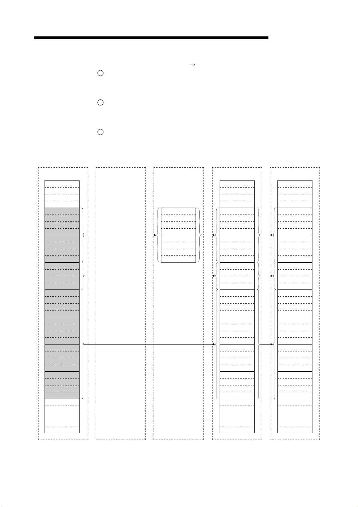
4 FUNCTIONS
Master station
Remote register
(RWw)
RWw0
RWw1
RWw2
RWw3
RWw4
RWw5
RWw6
RWw7
RWw8
RWw9
RWwA
RWwB
RWwC
RWwD
RWwE
RWwF
RWw10
RWw11
RWw12
RWw13
RWw14
RWw15
RWw16
RWw17
RWw18
RWw19
RWw1A
RWw1B
RWw1C
RWw1D
RWw1E
RWw1F
RWw20
MELSEC-QnA
[Word data from the master station
8
With the TO instruction, the word data to be sent to remote device station and all
remote device station/all local stations]
local station is written to the master station's "remote register (RWw)" in the buffer
memory.
9
The data in the "remote register (RWw)" in the buffer memory is automatically (for
each link scan) stored to remote device station's remote register (RWw) and all
local stations' remote registers (RWr).
10
The transmission data to the remote device station's remote register (RWw) is also
sent to the local stations.
Remote I/O station
(station No. 1:
occupies 1 station)
Remote device station
(station No. 2:
occupies 2 stations)
Remote register
(RWw)
RWw0
RWw1
RWw2
RWw3
RWw4
RWw5
RWw6
RWw7
Local station
(station No.4:
occupies 1 stations)
Remote register
(RWr)
RWr0
RWr1
RWr2
RWr3
RWr4
RWr5
RWr6
RWr7
RWr8
RWr9
RWrA
RWrB
RWrC
RWrD
RWrE
RWrF
RWr10
RWr11
RWr12
RWr13
RWr14
RWr15
RWr16
RWr17
RWr18
RWr19
RWr1A
RWr1B
RWr1C
RWr1D
RWr1E
RWr1F
RWr20
Local station
(station No.5:
occupies 4 stations)
Remote register
(RWr)
RWr0
RWr1
RWr2
RWr3
RWr4
RWr5
RWr6
RWr7
RWr8
RWr9
RWrA
RWrB
RWrC
RWrD
RWrE
RWrF
RWr10
RWr11
RWr12
RWr13
RWr14
RWr15
RWr16
RWr17
RWr18
RWr19
RWr1A
RWr1B
RWr1C
RWr1D
RWr1E
RWr1F
RWr20
to
RWwFF
4 - 20
to
RWrFF
to
RWrFF
Page 97
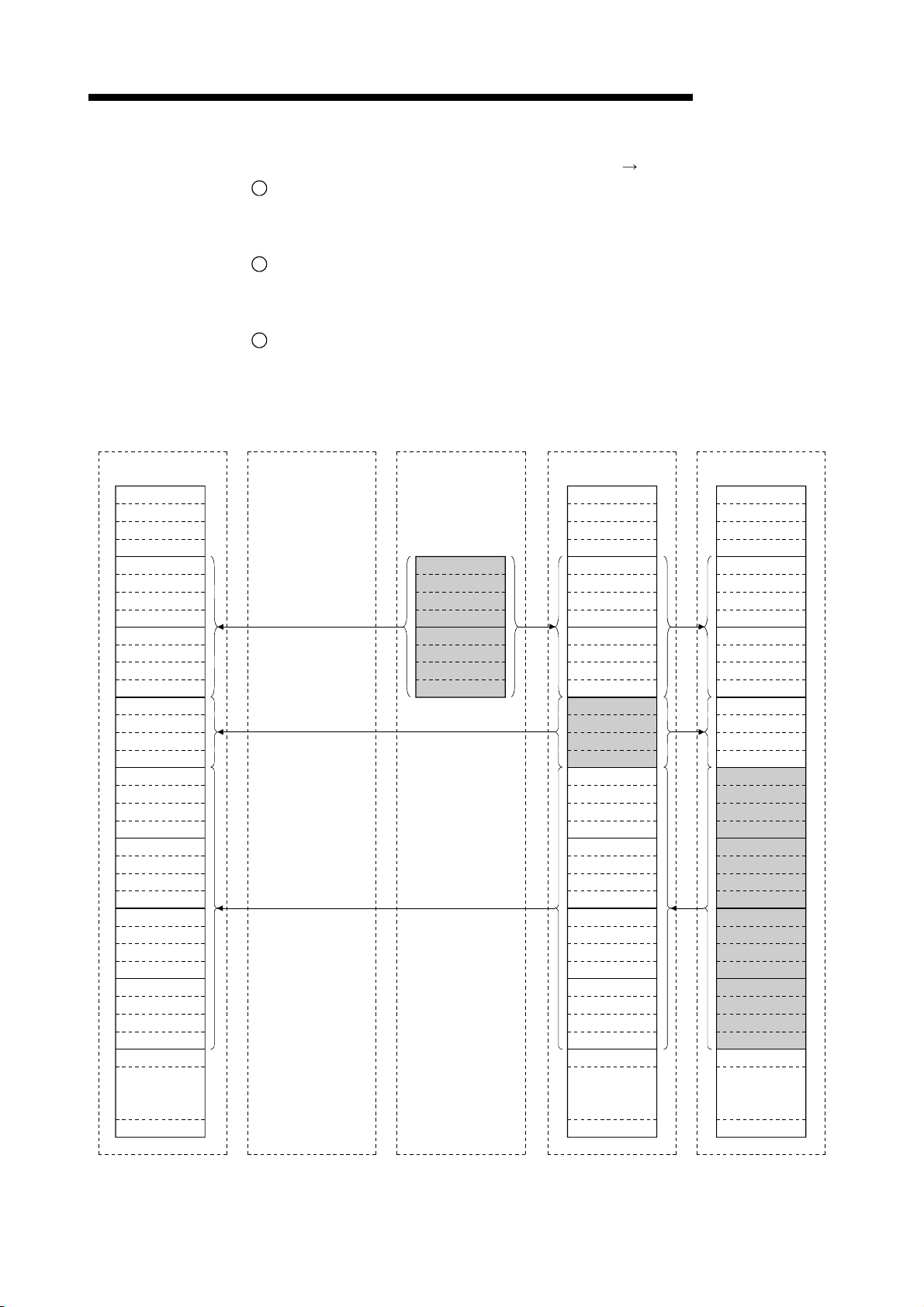
4 FUNCTIONS
Master station
Remote register
(RWr)
RWr0
RWr1
RWr2
RWr3
RWr4
RWr5
RWr6
RWr7
RWr8
RWr9
RWrA
RWrB
RWrC
RWrD
RWrE
RWrF
RWr10
RWr11
RWr12
RWr13
RWr14
RWr15
RWr16
RWr17
RWr18
RWr19
RWr1A
RWr1B
RWr1C
RWr1D
RWr1E
RWr1F
RWr20
MELSEC-QnA
[Word data from the remote device station/local station
11
The data in the remote device station's remote register (RWr) is automatically (for
the master station]
each link scan) stored in the master station's remote register (RWr) and all local
stations' remote registers (RWw).
12
The data in the local station's "remote register (RWw)" in the buffer memory is
automatically (for each link scan) stored in the master station's remote register
(RWr) and other local station's remote register (RWr).
13
The data of the remote device and local stations stored in the "remote register
(RWr)" in the buffer memory is written to the programmable controller CPU with the
FROM instruction.
Remote I/O station
(station No. 1:
occupies 1 station)
Remote device station
(station No. 2:
occupies 2 stations)
Remote register
(RWr)
RWr0
RWr1
RWr2
RWr3
RWr4
RWr5
RWr6
RWr7
Local station
(station No.4:
occupies 1 stations)
Remote register
(RWw)
RWw0
RWw1
RWw2
RWw3
RWw4
RWw5
RWw6
RWw7
RWw8
RWw9
RWwA
RWwB
RWwC
RWwD
RWwE
RWwF
RWw10
RWw11
RWw12
RWw13
RWw14
RWw15
RWw16
RWw17
RWw18
RWw19
RWw1A
RWw1B
RWw1C
RWw1D
RWw1E
RWw1F
RWw20
Local station
(station No.5:
occupies 4 stations)
Remote register
(RWw)
RWw0
RWw1
RWw2
RWw3
RWw4
RWw5
RWw6
RWw7
RWw8
RWw9
RWwA
RWwB
RWwC
RWwD
RWwE
RWwF
RWw10
RWw11
RWw12
RWw13
RWw14
RWw15
RWw16
RWw17
RWw18
RWw19
RWw1A
RWw1B
RWw1C
RWw1D
RWw1E
RWw1F
RWw20
to
RWrFF
4 - 21
to
RWwFF
to
RWwFF
Page 98
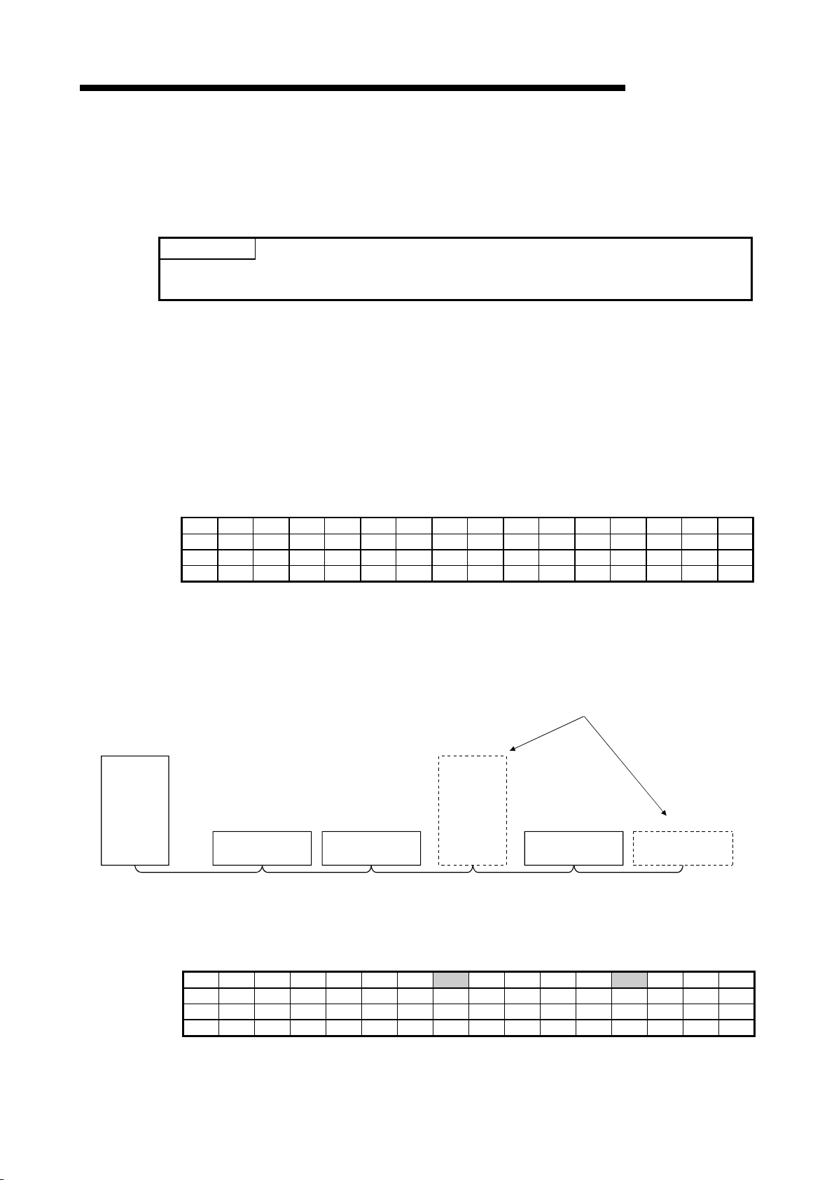
4 FUNCTIONS
MELSEC-QnA
4.6 Reserved Station Function
This is a function to treat the remote and local stations that are not actually connected
(but planned for connection in the future) not as "data-link faulty stations".
POINT
If already connected remote and local stations are set as reserved station, the specified
remote and local stations cannot perform data link at all.
(1) Setting method
The reserved station specification is performed with parameters (buffer memory
address 10
H to 13H).
Turn on the bit corresponding to the station number of the station to be reserved.
However, for remote/local stations that occupy more than 2 stations, turn on the
only bit corresponding to the station number set in the module's station number
setting switch.
The buffer memory configuration is shown below. (1 to 64 indicates station
Address b15 b14 b13 b12 b11 b10 b9 b8 b7 b6 b5 b4 b3 b2 b1 b0
10
H 16 15 14 13 12 11 10 9 8 7 6 5 4 3 2 1
11H 32 31 30 29 28 27 26 25 24 23 22 21 20 19 18 17
12H 48 47 46 45 44 43 42 41 40 39 38 37 36 35 34 33
13H 64 63 62 61 60 59 58 57 56 55 54 53 52 51 50 49
numbers.)
(2) Setting example
(a) System configuration example
When one local station and one remote station are to be connected in the
future to the system with three remote stations:
Modules to be connected in the future
Station No. 4
Master
station
Station No. 1
Remote station
(occupies 2 stations)
Station No. 3
Remote station
(occupies 1 station)
Local station
(occupies 4
stations)
Station No. 8
Remote station
(occupies 1 station)
Station No. 9
Remote station
(occupies 1 station)
(b) Buffer memory setting example
Turn on the 3rd bit, corresponding to station No. 4, and 8th bit,
Address b15 b14 b13 b12 b11 b10 b9 b8 b7 b6 b5 b4 b3 b2 b1 b0
10
H 0 0 0 0 0 0 0 1 0 0 0 0 1 0 0 0
11H 0 0 0 0 0 0 0 0 0 0 0 0 0 0 0 0
12H 0 0 0 0 0 0 0 0 0 0 0 0 0 0 0 0
13H 0 0 0 0 0 0 0 0 0 0 0 0 0 0 0 0
corresponding to station No. 9. (Set "264" for address 10
4 - 22
H.)
Page 99
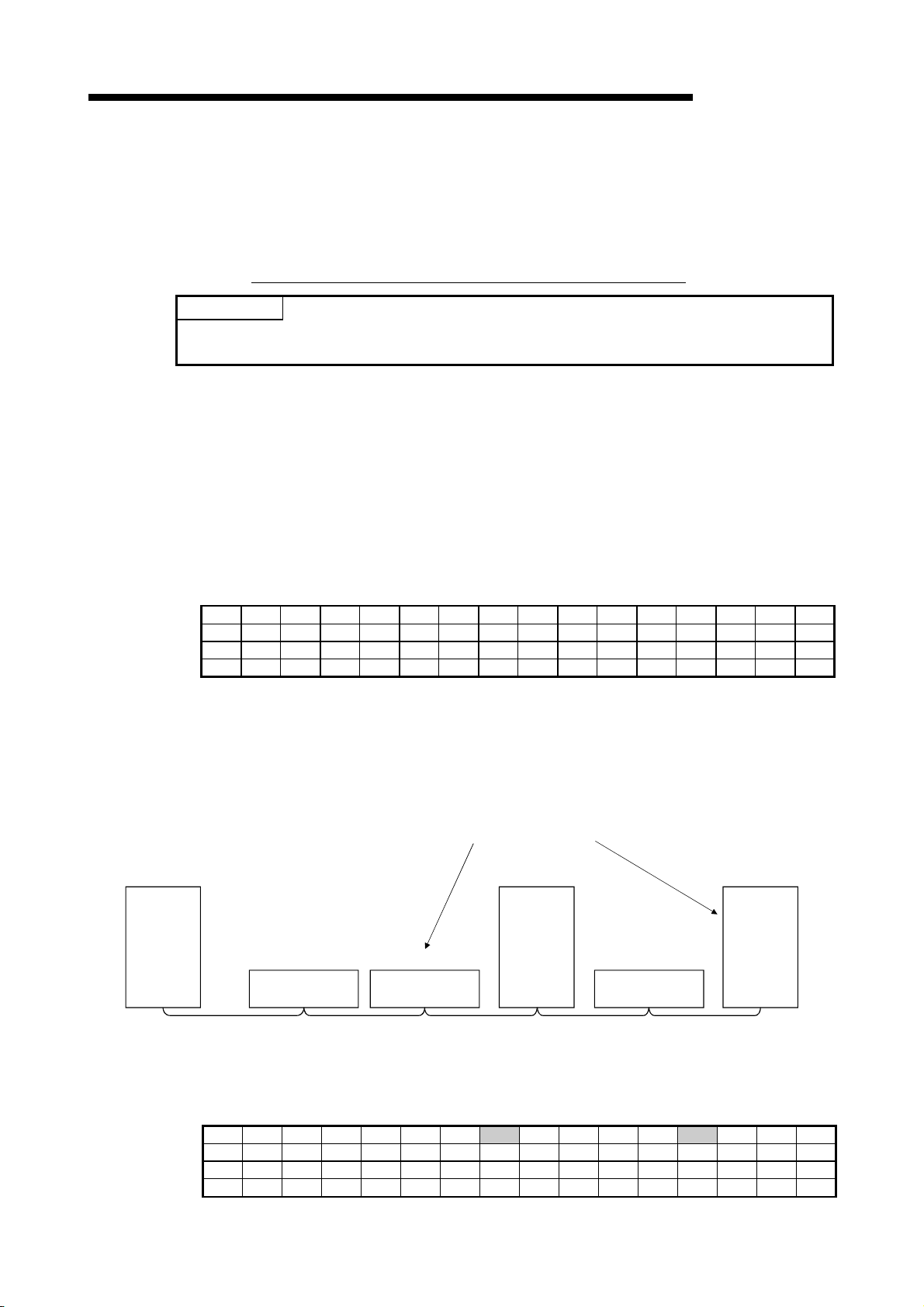
4 FUNCTIONS
MELSEC-QnA
4.7 Error Invalid Station Function
This is a function to treat the remote and local stations that cannot perform data links
due to power off, etc. not as "data-link faulty stations" on the master station and the
local station.
POINT
Be careful, however, for errors will not be detected at all if set so.
If the remote or local station set as the invalid station and also "specified as a reserved
station", the reserved station function has priority.
(1) Setting method
The invalid station specification is performed with parameters (buffer memory
address 14
H to 17H).
Turn on the bit corresponding to the station number to be set as invalid.
However, for the remote/local station which occupies more than 2 stations, turn
on the only bit corresponding to the station number set with the module's station
number setting switch.
The buffer memory configuration is shown below. (1 to 64 indicates station
Address b15 b14 b13 b12 b11 b10 b9 b8 b7 b6 b5 b4 b3 b2 b1 b0
14
H 16 15 14 13 12 11 10 9 8 7 6 5 4 3 2 1
15H 32 31 30 29 28 27 26 25 24 23 22 21 20 19 18 17
16H 48 47 46 45 44 43 42 41 40 39 38 37 36 35 34 33
17H 64 63 62 61 60 59 58 57 56 55 54 53 52 51 50 49
numbers.)
(2) Setting example
(a) System configuration example
When specifying the remote station No.3 and local station No.7 as invalid
stations in a system where three remote and two local stations are
connected:
Modules to be set as error invalid
Station No. 7
Local station
(occupies 4
stations)
Master
station
Station No. 1
Remote station
(occupies 2 stations)
Station No. 3
Remote station
(occupies 1 station)
Station No. 4
Local station
(occupies 1
station)
Station No. 5
Remote station
(occupies 2 stations)
(b) Buffer memory setting example
Turn on the 2nd bit, corresponding to station No. 3, and 6th bit,
Address b15 b14 b13 b12 b11 b10 b9 b8 b7 b6 b5 b4 b3 b2 b1 b0
H 0 0 0 0 0 0 0 1 0 0 0 0 1 0 0 0
14
15H 0 0 0 0 0 0 0 0 0 0 0 0 0 0 0 0
16H 0 0 0 0 0 0 0 0 0 0 0 0 0 0 0 0
17H 0 0 0 0 0 0 0 0 0 0 0 0 0 0 0 0
corresponding to station No. 7. (Set "68" for address 14
4 - 23
H.)
Page 100

4 FUNCTIONS
MELSEC-QnA
4.8 Data Link Status Setting When the Master Station Programmable Controller CPU Has an Error
The data link status for when the master station's programmable controller CPU has
an "operation-stop error" can be set.
The data link between local stations can be continued.
POINT
Even if the master station programmable controller CPU has an "operation-stop error", the
data link continues.
[Setting method]
Set to the "operation specification when the CPU is down (address 6
parameter information area of the master station's buffer memory
0......Stop (default)
1......Continue
H)" in the
4 - 24
 Loading...