

Page 1
Contents
1. Safety precautions ..............................................................4
1-1. General precautions ...................................................................4
1-2. Precautions for relocating or repairing the unit ...........................5
1-3. Additional precautions .................................................................5
2. Introduction .........................................................................6
2-1. Terms used in this manual ..........................................................6
2-2. Required licenses .......................................................................6
2-3. About this manual .......................................................................6
3. Basic operations .................................................................7
3-1. Monitor/Operation .......................................................................7
3-2. Energy Management ................................................................21
3-3. Schedule ...................................................................................24
3-4. Status List .................................................................................44
3-5. Malfunction Log ........................................................................48
4. Practical operations ..........................................................50
4-1. Cleaning the touch panel ..........................................................50
5. Initial startup settings ........................................................51
5-1. Initial startup setting procedures ...............................................51
5-2. Initial Settings ...........................................................................56
5-3. Environment settings for Integrated Centralized
Control Web ..............................................................................80
6. Maintenance .....................................................................84
6-1. Backing up settings data ...........................................................84
6-2. Importing settings data .............................................................85
6-3. Software Update .......................................................................86
6-4. Software information .................................................................88
7. Specifications ....................................................................89
Air Conditioning Control System
Centralized Controller
AE-200A/AE-50A
AE-200E/AE-50E
Instruction Book
Before using the controller, please read this Instruction Book carefully to ensure proper operation.
Retain this manual for future reference.
Page 2

2
WT07982X03
Contents
1. Safety precautions ..............................................................................................4
1-1. General precautions ................................................................................................ 4
1-2. Precautions for relocating or repairing the unit ....................................................... 5
1-3. Additional precautions ............................................................................................. 5
2. Introduction .........................................................................................................6
2-1. Terms used in this manual ......................................................................................6
2-2. Required licenses ................................................................................................... 6
2-3. About this manual ................................................................................................... 6
3. Basic operations ..................................................................................................7
3-1. Monitor/Operation ................................................................................................... 7
3-1-1. Screen sequence.......................................................................................... 7
3-1-2. Group icons .................................................................................................. 9
3-1-3. Checking the operation conditions ............................................................... 9
3-1-4. Selecting the icons of the groups to be operated ....................................... 13
3-1-5. Operation settings screen........................................................................... 19
3-2. Energy Management ............................................................................................. 21
3-2-1. Energy Use Status...................................................................................... 21
3-2-2. Ranking ...................................................................................................... 22
3-2-3. Target value ................................................................................................ 23
3-3. Schedule ............................................................................................................... 24
3-3-1. Weekly Schedule ........................................................................................ 26
3-3-2. Annual Schedule......................................................................................... 36
3-3-3. Today’s Schedule ....................................................................................... 42
3-4. Status List ............................................................................................................. 44
3-4-1. Malfunction List........................................................................................... 44
3-4-2. Filter Sign List ............................................................................................. 46
3-5. Malfunction Log ..................................................................................................... 48
3-5-1. Unit Error/Communication Error ................................................................. 48
4. Practical operations ...........................................................................................50
4-1. Cleaning the touch panel ...................................................................................... 50
5. Initial startup settings ........................................................................................51
5-1. Initial startup setting procedures ........................................................................... 51
5-1-1. AE-200 initial start-up for a system without connection to an
AE-50/EW-50 controller .............................................................................. 52
5-1-2. AE-200 initial start up for a system with connection to one or more
AE-50/EW-50 controllers ............................................................................ 53
5-2. Initial Settings ........................................................................................................ 56
5-2-1. Logging in to the Initial Settings menu ....................................................... 56
5-2-2. Locking the screen ..................................................................................... 58
5-2-3. Date and time ............................................................................................. 59
5-2-4. License registration for optional functions .................................................. 61
Page 3

3
WT07982X03
5-2-5. Unit Information .......................................................................................... 62
5-2-6. Network ...................................................................................................... 66
5-2-7. Groups ........................................................................................................ 70
5-2-8. Blocks ......................................................................................................... 72
5-2-9. Floor Layout................................................................................................ 73
5-2-10. System View ............................................................................................. 78
5-2-11. Floor Layout settings on the Integrated Centralized Control Web ............ 79
5-3. Environment settings for Integrated Centralized Control Web .............................. 80
5-3-1. Operating environment ............................................................................... 80
5-3-2. System Settings.......................................................................................... 81
5-3-3. Setting the IP address of the PC ................................................................ 82
5-3-4. Logging in to the Integrated Centralized Control Web ................................ 83
6. Maintenance ......................................................................................................84
6-1. Backing up settings data ....................................................................................... 84
6-2. Importing settings data .......................................................................................... 85
6-3. Software Update ................................................................................................... 86
6-3-1. Preparation ................................................................................................. 86
6-3-2. Update procedures ..................................................................................... 87
6-4. Software information ............................................................................................. 88
7. Specifications .................................................................................................... 89
Page 4
4
WT07982X03
1. Safety precautions
►Observe these precautions carefully to ensure safety.
►After reading this manual, pass the manual on to the end user to retain for future
reference.
►The user should keep this manual for future reference and refer to it as necessary. This
manual should be made available to those who repair or relocate the units. Make sure
that the manual is passed on to any future air conditioning system user.
: indicates a hazardous situation which, if not avoided, could result in
death or serious injury.
: indicates a hazardous situation which, if not avoided, could result in
minor or moderate injury.
: addresses practices not related to personal injury, such as product
and/or property damage.
1-1. General precautions
Do not install the controller in areas where large amounts of oil, steam, organic solvents,
or corrosive gases (such as ammonia, sulfuric compounds, or acids), or areas where
acidic/alkaline solutions or special chemical sprays are used frequently. These substances
may significantly reduce the performance and corrode the internal parts, resulting in
electric shock, malfunction, smoke, or fire.
To reduce the risk of short circuits, current leakage, electric shock, malfunction, smoke, or
fire, do not wash the controller with water or any other liquid.
To reduce the risk of electric shock, malfunction, smoke, or fire, do not touch the electrical
parts, USB memory, or touch panel with wet fingers.
To reduce the risk of injury or electric shock, before spraying a chemical around the
controller, stop the operation and cover the controller.
To reduce the risk of injury, keep children away while installing, inspecting, or repairing the
controller.
If you notice any abnormality (e.g., burning smell), stop the operation, turn off the
controller, and consult your dealer. Continuing the operation may result in electric shock,
malfunction, or fire.
Properly install all required covers to keep moisture and dust out of the controller. Dust
accumulation and the presence of water may result in electric shock, smoke, or fire.
To reduce the risk of fire or explosion, do not place flammable materials or use flammable
sprays around the controller.
To reduce the risk of electric shock or malfunction, do not touch the touch panel, switches,
or buttons with a sharp object.
To avoid injury from broken glass, do not apply excessive force to the glass parts.
To reduce the risk of injury, electric shock, or malfunction, avoid contact with the sharp
edges of certain parts.
Page 5
5
WT07982X03
Consult your dealer for the proper disposal of the controller. Improper disposal will pose a
risk of environmental pollution.
1-2. Precautions for relocating or repairing the unit
The controller must be repaired or moved only by qualified personnel. Do not disassemble
or modify the controller. Improper installation or repair may result in injury, electric shock,
or fire.
1-3. Additional precautions
To avoid discoloration, do not use benzene, thinner, or chemical rag to clean the controller.
When the controller is heavily soiled, wipe the controller with a well-wrung cloth that has
been soaked in water with mild detergent, and then wipe off with a dry cloth.
This appliance is not intended for use by persons (including children) with reduced
physical, sensory or mental capabilities, or lack of experience and knowledge, unless they
have been given supervision or instruction concerning use of the appliance by a person
responsible for their safety. Children should be supervised to ensure that they do not play
with the appliance.
Page 6

6
WT07982X03
2. Introduction
AE-200A/AE-50A/AE-200E/AE-50E is a centralized controller.
EW-50A/EW-50E is an LCD-less total management system.
Any connected air conditioning systems can be operated or monitored on the AE-200A/AE-50A/AE-200E/AE-50E’s
LCD or the Integrated Centralized Control Web.
By using a PI controller that is built-in on the AE-200A/AE-50A/EW-50A/AE-200E/AE-50E/EW-50E, the energycontrol-related status can be displayed and Peak Cut control can be performed without a use of a PI controller
(PAC-YG60MCA).
Each AE-200A/AE-50A/AE-200E/AE-50E can control up to a total of 50 indoor units and other equipment. By
connecting AE-200A/AE-200E (main controller) and AE-50A/AE-50E/EW-50A/EW-50E (sub controllers), up to 200
indoor units and other equipment can be controlled.
2-1. Terms used in this manual
- “Centralized Controller AE-200A/AE-200E” is referred to as “AE-200.”
- “Centralized Controller AE-50A/AE-50E” is referred to as “AE-50.”
- “Centralized Controller EW-50A/EW-50E” is referred to as “EW-50.”
2-2. Required licenses
The required licenses vary, depending on the functions to be used. Refer to the License Classification List for
details. Purchase the required licenses from your dealer. Refer to section 5-2-4 for license registration.
2-3. About this manual
This manual explains how to make basic operations of the LCD and the Integrated Centralized Control Web, and
also how to make settings required when the controller is installed. For settings methods when the controller is
installed, refer to section 5 “Initial startup settings”. For further information of operation methods and function
settings such as how to monitor and operate the units other than air conditioning units, refer to the following
Instruction Books. Ask your dealer for how to obtain these Instruction Books.
AE-200A/AE-50A/EW-50A AE-200E/AE-50E/EW-50E Instruction Book (Initial Settings)
AE-200A/AE-50A AE-200E/AE-50E Instruction Book (Detailed operations)
AE-200A/AE-50A/EW-50A AE-200E/AE-50E/EW-50E Instruction Book (Integrated Centralized Control Web)
Page 7
7
WT07982X03
3. Basic operations
3-1. Monitor/Operation
Unit groups can be monitored and operated on the AE-200/AE-50’s LCD or the Integrated Centralized Control Web.
This section explains how to monitor and operate the unit groups.
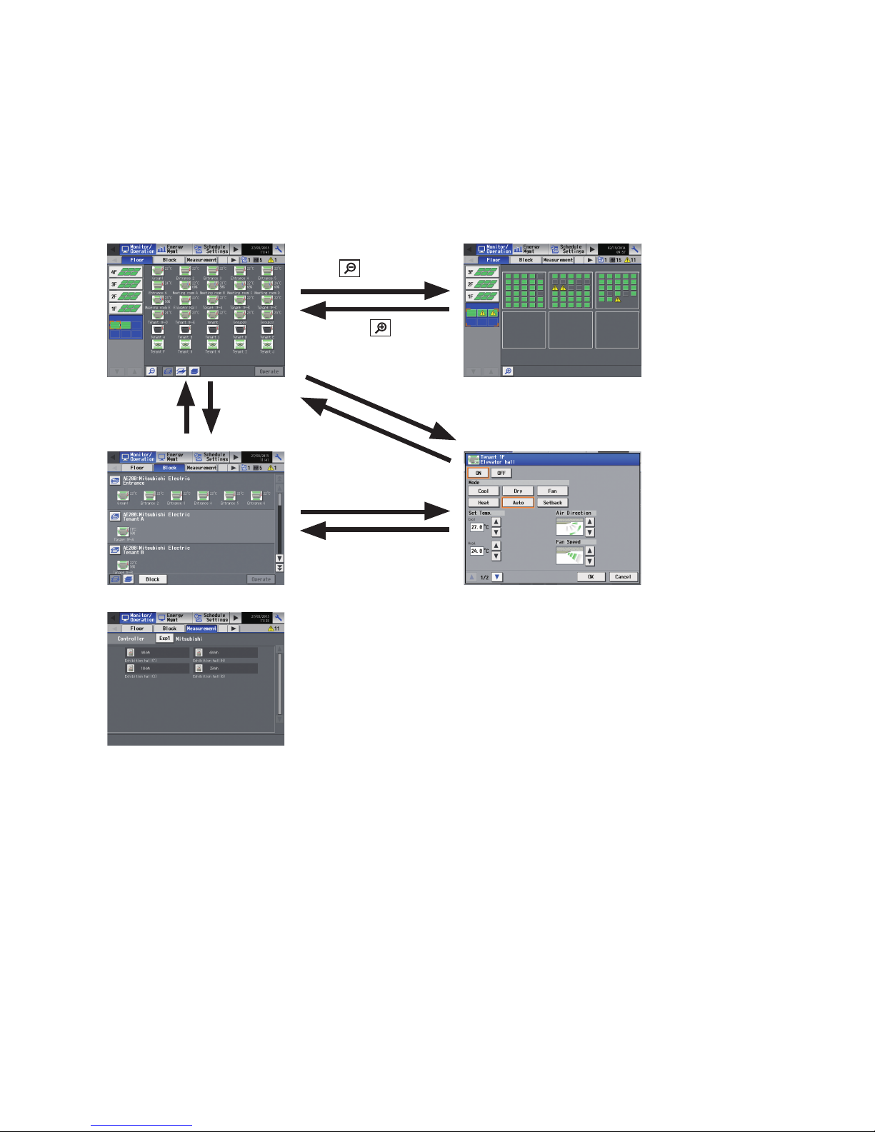
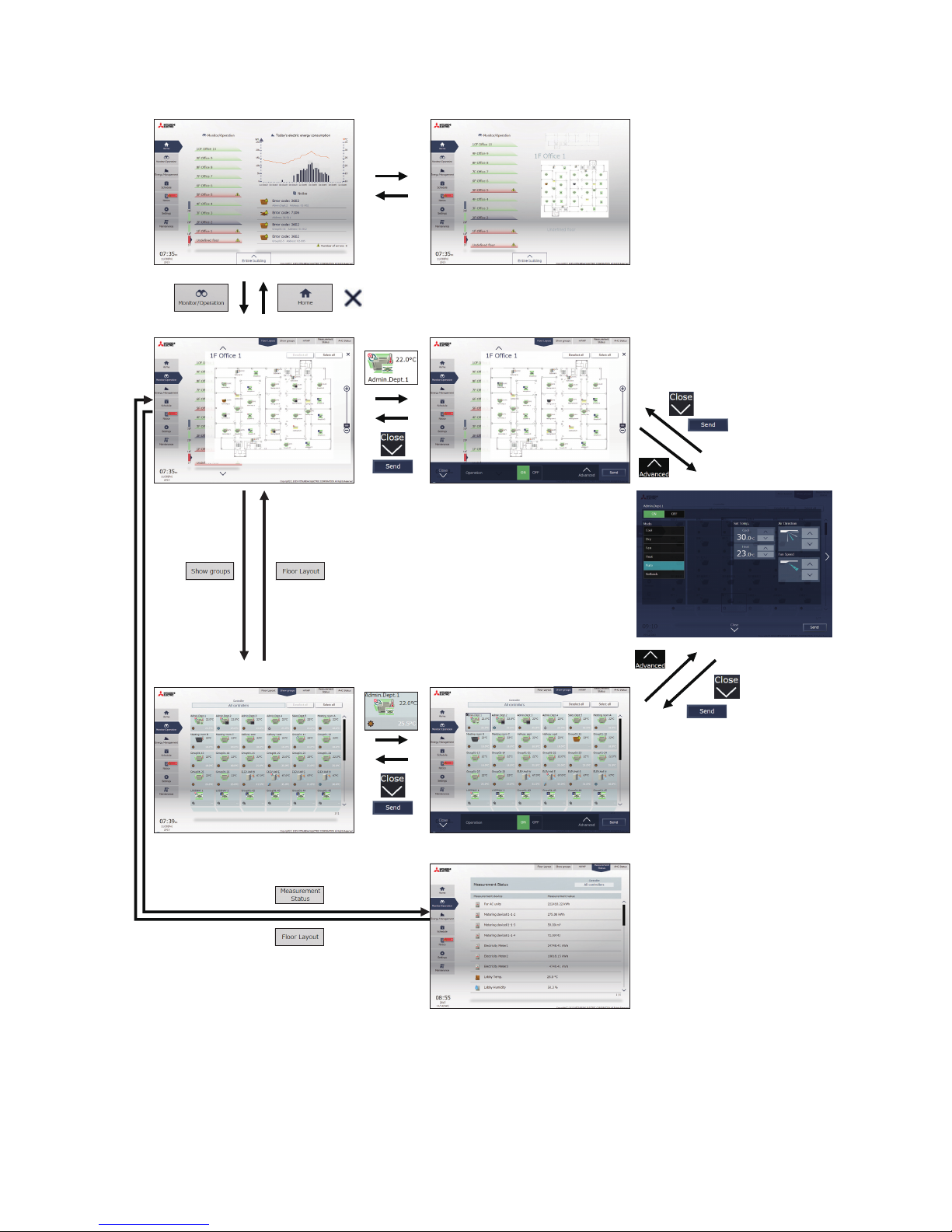
3-1-1. Screen sequence
3-1-1-1. LCD
[Floor] display (zoomed-in) [Floor] display (zoomed-out)
[Block] display Operation settings screen
[Measurement] display
For further information of operation methods for each function, refer to the Instruction Book (Detailed operations).
Touch [ ].
Touch [
].
Select a group and
touch [Operate].
Touch [Block].
Touch [OK] or
[Cancel].
Touch [Floor].
Select a group and
touch [Operate].
Touch [OK] or [Cancel].
* The [Measurement] tab will appear only when an AI or PI controller is connected or when the AE-200 built-in PI controller is enabled.
Page 8
8
WT07982X03
3-1-1-2. Integrated Centralized Control Web
Home Home (preview)
Floor Layout
Floor Layout (simple operation)
Advanced settings
Group list Group list (simple operation)
Measurement status
Page 9
9
WT07982X03
3-1-2. Group icons
Each group icon indicates the operation condition of the group. Touch the icon, and then touch [Operate] to bring up
the operation settings screen.
Air conditioning unit group
ON OFF Error Schedule set
Note: Refer to the Instruction Book (Detailed operations) or Instruction Book (Integrated Centralized Control Web) for details and
other icons.
3-1-3. Checking the operation conditions
This section explains how to display the operation conditions of units.
3-1-3-1. LCD
[1] [Floor] display
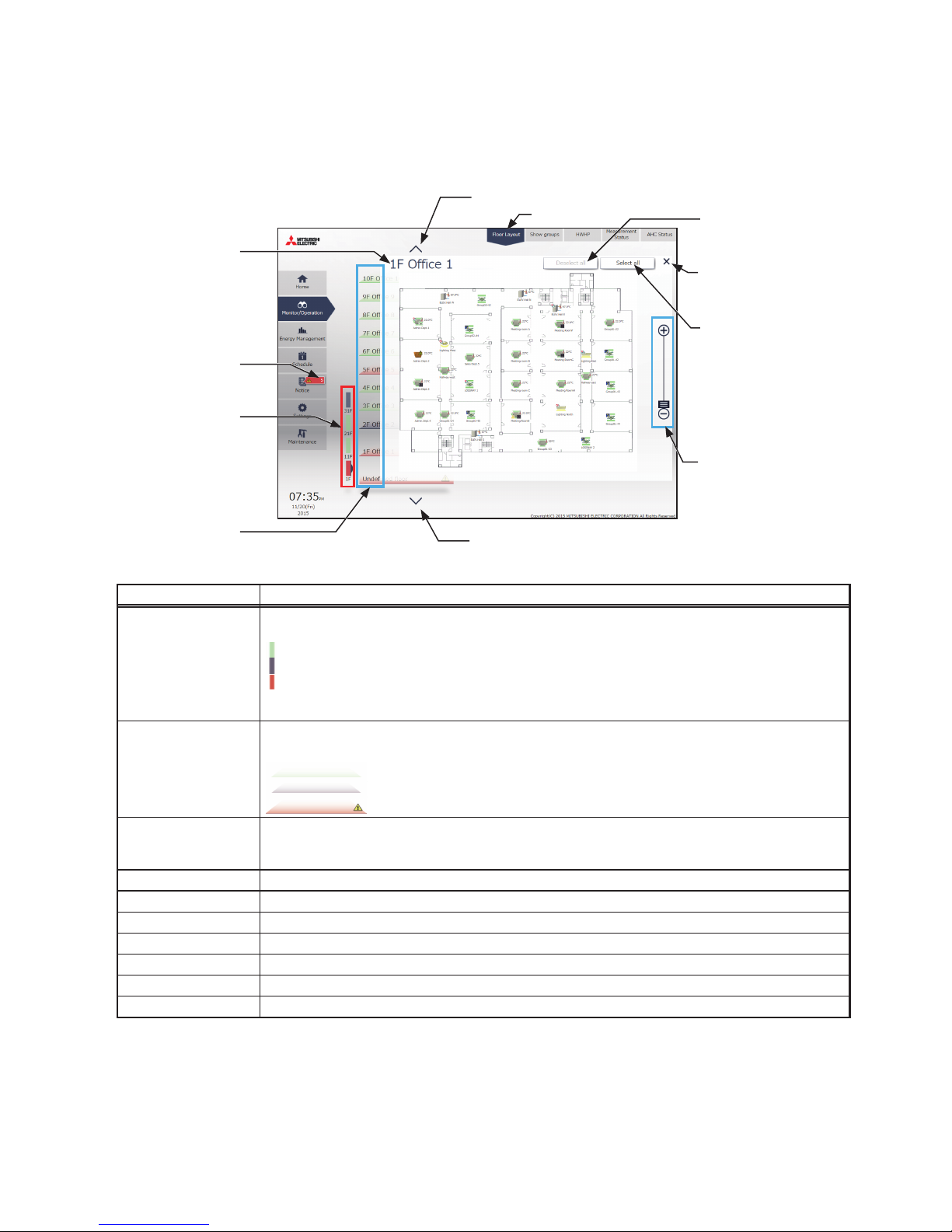
Touch [Monitor/Operation] in the menu bar, and then touch [Floor].
Note: The unit groups that are under the control of AE-200, AE-50, and EW-50 can be displayed.
Floor selection
Area selection
Group icons
The icon indicates the
operation condition of the
group.
Zoom-out/Zoom-in
Deselect-all
Select-all-groups-on-the-
floor
Select-all-groups
Weekly schedule number
Number of units in error
Number of units whose
filter sign is turned on
Group name
Room temperature
Operate
Touch to display the
operation settings screen of
the selected group.
Room humidity
Page 10
10
WT07982X03
Item Description
Floor selection Select a floor you want to monitor.
Area selection Select an area of the selected floor you want to monitor.
Group name The name of the group will appear.
Room temperature Indoor unit return air temperature will appear.
Room humidity The room humidity will appear.
Weekly schedule number The weekly schedule number that is currently effective will appear.
Number of units whose filter
sign is turned on
*1
The number of units whose filter sign is currently turned on will appear. Touching “ ” will
bring up the [Filter Sign] screen. (See section 3-4-2 “Filter Sign List”.)
Number of units in error
*1
The number of units that are currently in error will appear. Touching “ ” will bring up the
[Malfunction] screen. (See section 3-4-1 “Malfunction List”.)
Deselect-all Touch to cancel all group selections.
Select-all-groups-on-the-floor Touch to select all groups on the currently selected floor.
Select-all-groups Touch to select all groups.
Zoom-out Touch to display the status of the whole floor.
Zoom-in Touch to go to the zoomed-in screen.
*1 The item will not appear if the number of units is “0.”
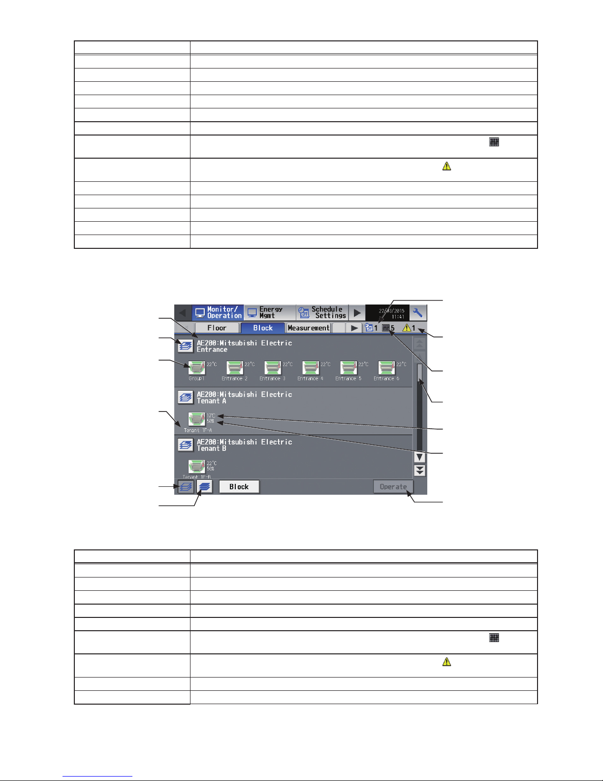
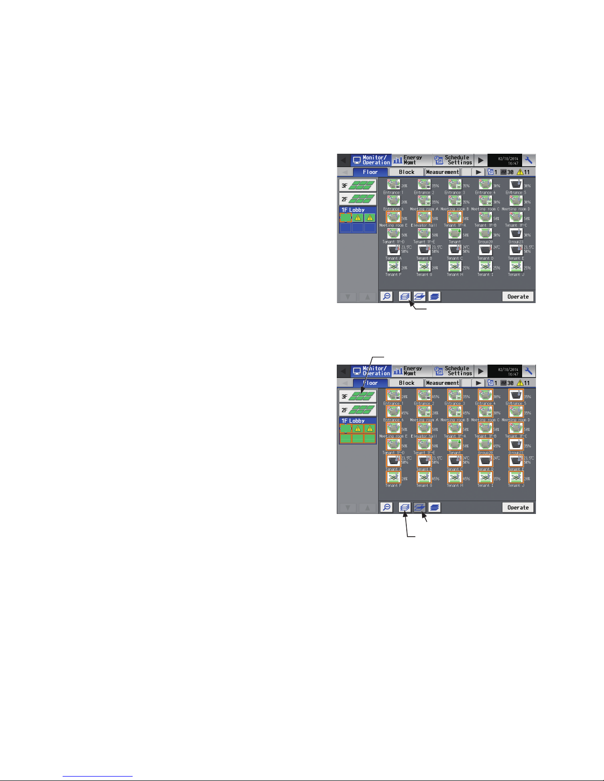
[2] [Block] display
Touch [Monitor/Operation] in the menu bar, and then touch [Block].
Item Description
Block selection Select a block you want to monitor.
Group name The name of the group will appear.
Room temperature Indoor unit return air temperature will appear.
Room humidity The room humidity will appear.
Weekly schedule number The weekly schedule number that is currently effective will appear.
Number of units whose filter
sign is turned on
*1
The number of units whose filter sign is currently turned on will appear. Touching “ ” will
bring up the [Filter Sign] screen. (See section 3-4-2 “Filter Sign List”.)
Number of units in error
*1
The number of units that are currently in error will appear. Touching “ ” will bring up the
[Malfunction] screen. (See section 3-4-1 “Malfunction List”.)
Deselect-all Touch to cancel all group selections.
Select-all-groups Touch to select all groups.
*1 The item will not appear if the number of units is “0.”
Block name
Group icons
The icon indicates the
operation condition of the
group.
Weekly schedule number
Number of units in error
Number of units whose
filter sign is turned on
Group name
Deselect-all
Select-all-groups
Scroll bar
Room temperature
Room humidity
Operate
Touch to display the
operation settings screen of
the selected block or group.
Block selection
Page 11
11
WT07982X03
3-1-3-2. Integrated Centralized Control Web
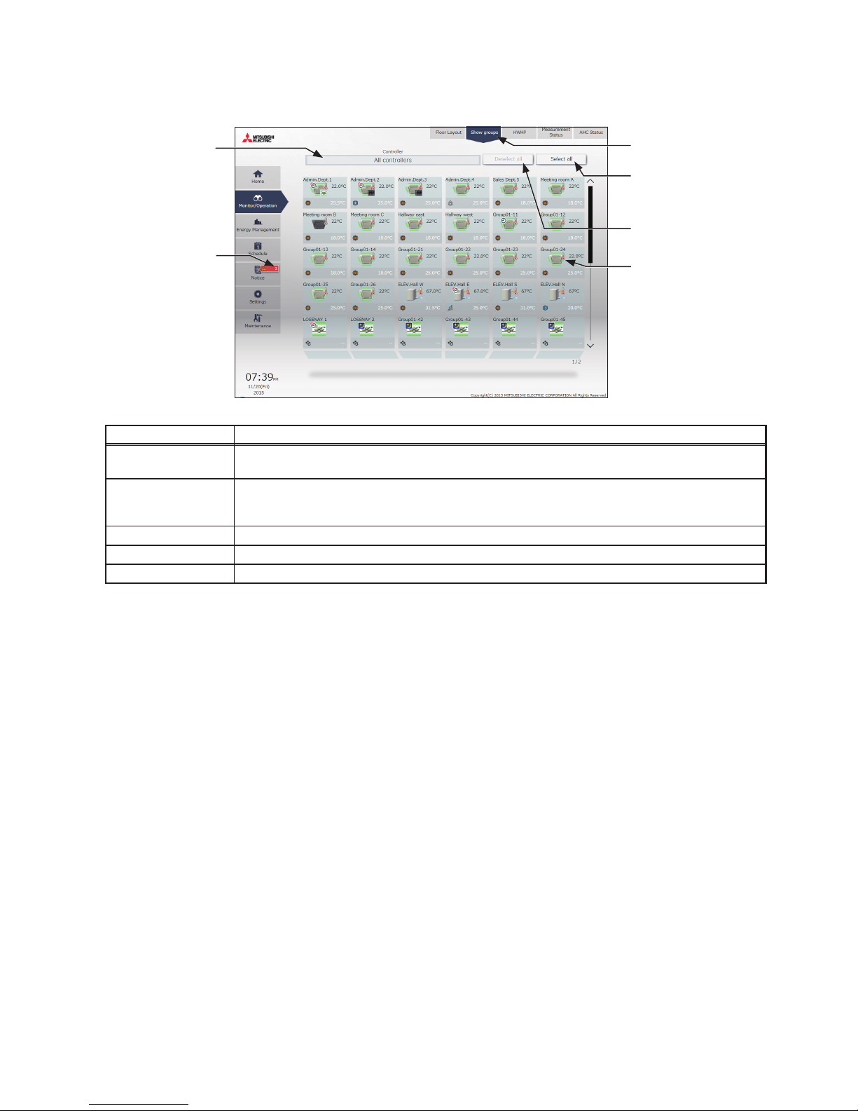
[1] Group display
Click [Monitor/Operation] in the menu, and then click [Show groups] to display the operation status of unit groups.
Item Description
Controller
Click to narrow down the unit groups to display into “Centralized controller units,” “Block units,” and
“Energy management block units.”
Number of units
currently in error
The number of units that are under the control of AE-200/AE-50/EW-50 and currently in error
will appear. Clicking [Notice] > [Error List] will bring up the Error List screen. (See section 3-4-1
“Malfunction List”.)
Select all Click to select all unit groups that are displayed.
Deselect all Click to cancel all selections at once.
Group icon Type and status of units that belong to the group will appear.
Controller
Select all
Deselect all
Group icon
Show groups
Number of units
currently in error
Page 12
12
WT07982X03
[2] Floor Layout display
Click [Monitor/Operation] in the menu, and then click [Floor Layout] or “Floor display area” to display the operation
status of unit groups on the floor layout. The floor layout to be displayed can be changed by clicking “Floor display
area” and “Displayed floor switching area” while the floor layout is displayed.
Note: If you click “Floor display area” in the Home screen, the menu changes to [Monitor/Operation] and the floor layout of the
clicked floor is displayed.
Note: If a floor layout is not registered, a floor layout will not be displayed.
Item Description
Displayed floor
switching area
Switches the floors displayed in the floor display area in units of 10 floors.
It simply displays the status of the air conditioning units registered to the floors.
(Green): One or more units on the floor are in operation.
(Gray): All units on the floor are stopped.
(Red): One or more units on the floor are in error.
Note: The number of buttons for switching displayed floors that are shown differs depending on the
settings configured in “Floor settings” of Initial Setting Tool.
Floor display area
Displays the operation status of the air conditioning units for 10 floors.
It simply displays the status of the air conditioning units registered to the floors.
: One or more units on the floor are in operation.
: All units on the floor are stopped.
: One or more units on the floor are in error.
Number of units
currently in error
The number of units that are under the control of AE-200/AE-50/EW-50 and currently in error
will appear. Clicking [Notice] > [Error List] will bring up the Error List screen. (See section 3-4-1
“Malfunction List”.)
Floor name The name of the floor shown is displayed.
Upper floor Click to move to the upper floor.
Lower floor Click to move to the lower floor.
Select all Click to select all unit groups that are displayed.
Deselect all Click to cancel all selections at once.
Close Click to close the Floor Layout screen.
Zoom bar Click to zoom in/out the floor layout.
Floor name
Number of units
currently in error
Displayed floor
switching area
Floor display area
Upper floor
Lower floor
Deselect all
Close
Select all
Zoom bar
Floor Layout
Gray
Green
Red
Page 13
13
WT07982X03
3-1-4. Selecting the icons of the groups to be operated
On the [Floor] or [Block] display under the [Monitor/Operation] menu, select the icon(s) of the group(s) to be
operated as explained below, and then touch [Operate] (click [Advanced] on the Integrated Centralized Control
Web) to bring up the operation settings screen.
3-1-4-1. LCD
[1] Selecting group icons
(1) Selecting a group
On the [Floor] or [Block] display, touch the icon(s) of the
group(s) you want to operate. The selected group icon(s)
will appear with an orange frame.
Touch again to deselect.
To cancel all group selections, touch the “Deselect-all”
button.
(2) Selecting all groups on the selected floor
On the [Floor] display, touch the floor(s) you want to
operate, and then touch the “Select-all-groups-on-thefloor” button. The selected floor and group icons will
appear with an orange frame.
To cancel all group selections, touch the “Deselect-all”
button.
Deselect-all
Select-all-groups-on-the-floor
Deselect-all
Floor selection
Page 14
14
WT07982X03
(3) Selecting all groups on all floors
On the [Floor] or [Block] display, touch the “Select-allgroups” button. All floor and group icons will appear with
an orange frame.
To cancel all group selections, touch the “Deselect-all”
button.
(4) Selecting all groups in the selected block
On the [Block] display, touch the block(s) you want to
operate. The selected block and group icons will appear
with an orange frame.
Touch again to deselect.
To cancel all group selections, touch the “Deselect-all”
button.
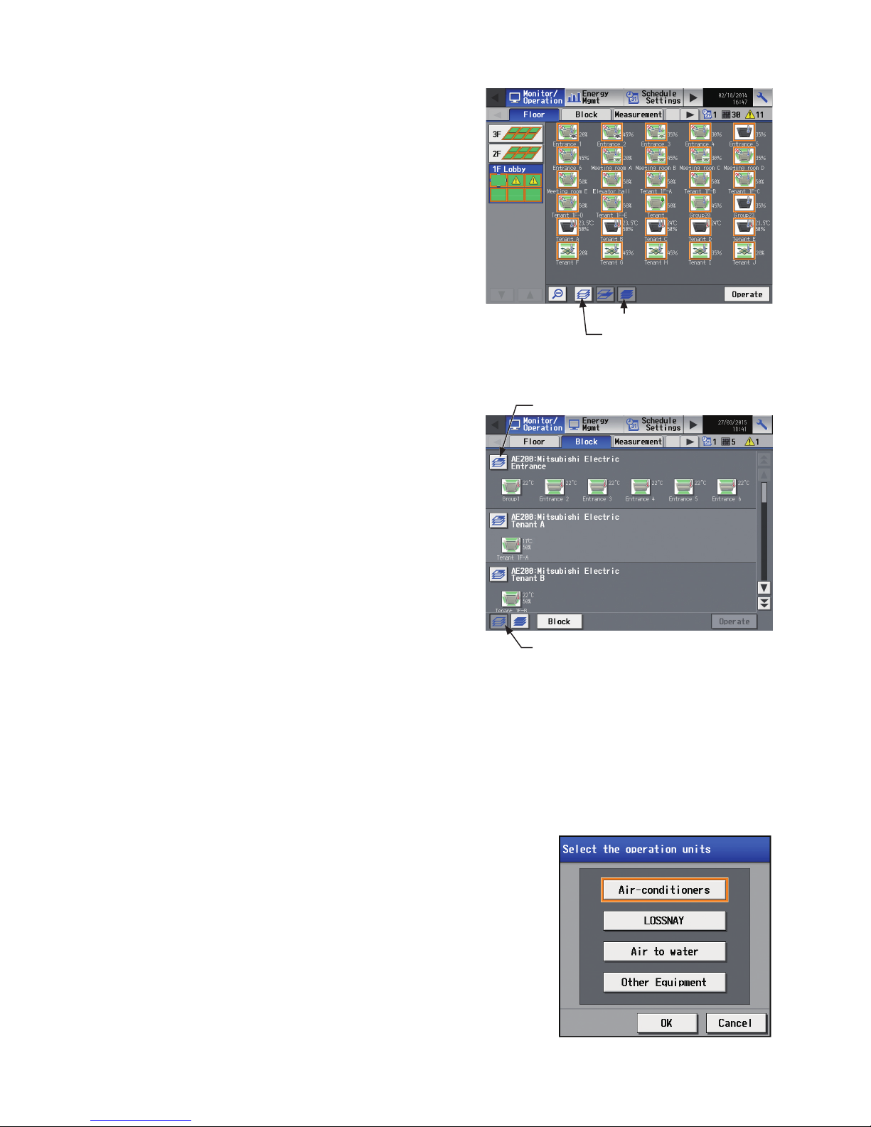
[2] Selecting equipment type
(1) When the equipment types of all selected groups are the same
Selecting the group icons and touching [Operate] will bring up the operation settings screen for the selected
groups.
Refer to section 3-1-5 “Operation settings screen” for details about the operation settings.
(2) When the equipment types of the selected groups are different
Selecting the group icons and touching [Operate] will bring up the
equipment type selection screen.
Touch the equipment type(s) you want to operate, and then touch [OK]
to bring up the operation settings screen for the selected equipment
groups.
Refer to section 3-1-5 “Operation settings screen” for details about
the operation settings.
Note: When two or more equipment types are selected, only the [ON/OFF],
[Schedule], and [Hold] settings will appear on the operation settings
screen.
Deselect-all
Select-all-groups
Deselect-all
Block icon
Page 15
15
WT07982X03
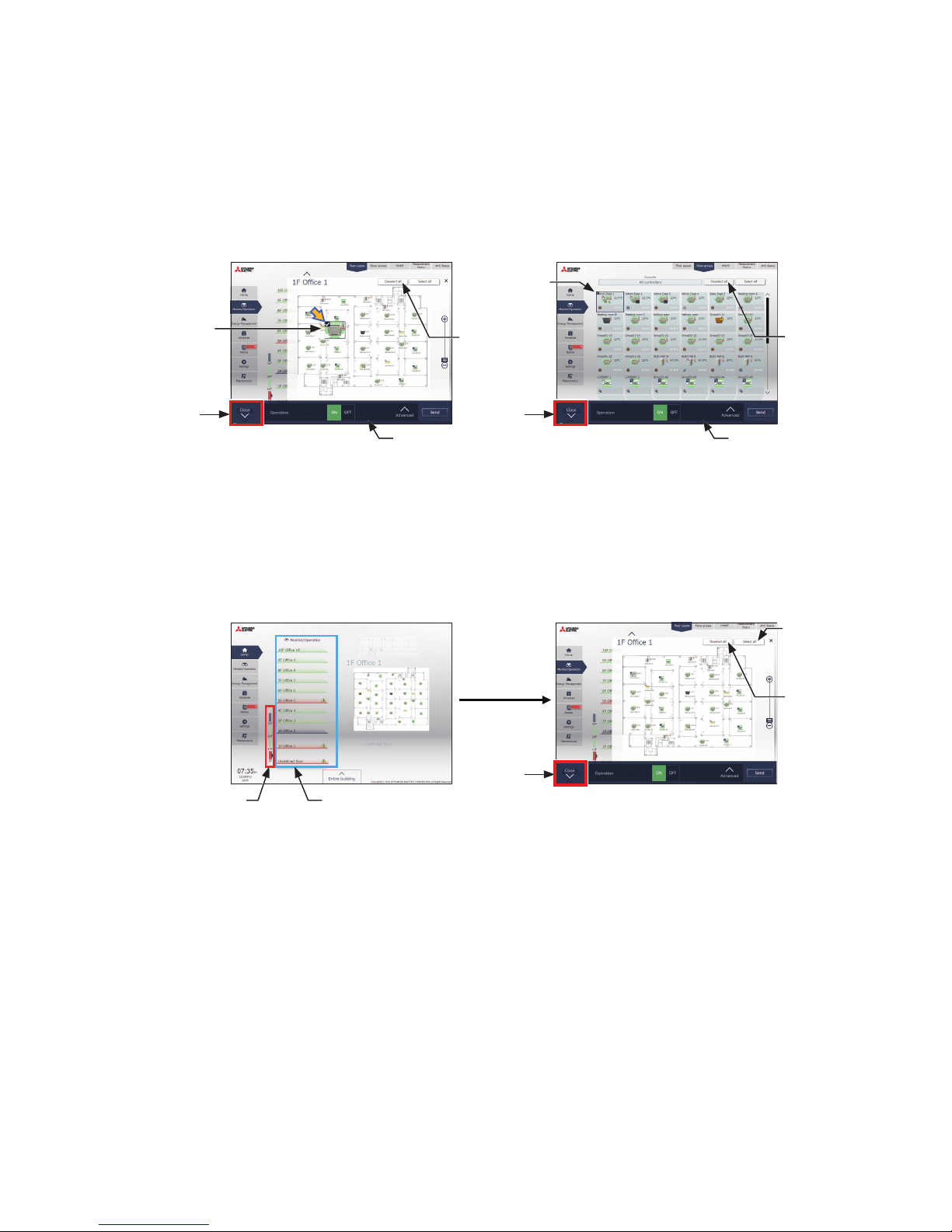
3-1-4-2. Integrated Centralized Control Web
[1] Selecting group icons
(1) Selecting unit group(s)
(1) In the Floor Layout screen or group list, click the icon(s) of the group(s) you want to operate.
The selected group icon(s) will appear with a checkmark and a dark blue frame.
Click again to deselect.
To cancel all group selections, click [Deselect all] or [Close] in the taskbar.
(2) Selecting all unit groups on the selected floor
(1) Select the floor for which you wish to perform operation by making a selection in “Displayed floor switching
area” and then “Floor display area” on the Home (Preview) screen, and then click [Select all] on the [Floor
Layout] screen.
All icon(s) on the selected floor will appear with a checkmark and a dark blue frame.
To cancel all group selections, click [Deselect all] or [Close] in the taskbar.
Floor Layout
Deselect
all
Group
selection
Close
Group
selection
Deselect all
Close
Group list
Taskbar Taskbar
Home (Preview)
Deselect
all
①Displayed floor
switching area
Select the unit of floors
that includes the floor for
which you wish to perform
operation.
Close
Floor Layout
② Floor display area
Select the floor for which
you wish to perform
operation.
Select all
Page 16
16
WT07982X03
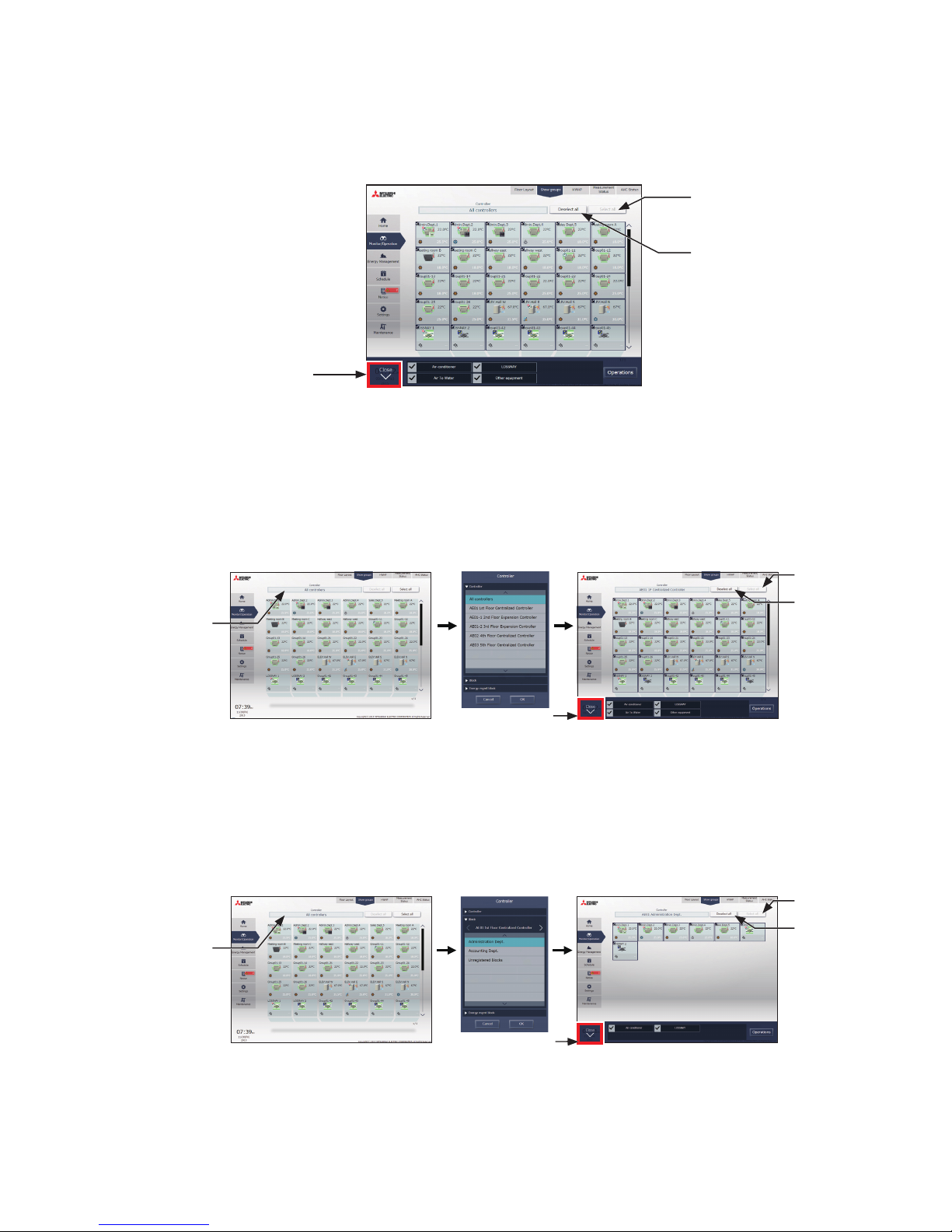
(3) Selecting all groups
(1) In the group list, click [Select all].
The all icon(s) will appear with a checkmark and a dark blue frame.
To cancel all group selections, click [Deselect all] or [Close] in the taskbar.
(4) Selecting all groups of a given centralized controller
(1) In the group list, click [Controller]. In the controller selection screen, select a centralized controller.
The unit groups that are under the control of the selected centralized controller will appear.
In the group list (centralized controller units), click [Select all]. All icons will appear with a checkmark and a
dark blue frame.
To cancel all group selections, click [Deselect all] or [Close] in the taskbar.
(5) Selecting all groups in a given block
(1) In the group list, click [Controller]. In the block selection screen, select a block.
The unit groups that belong to the selected block will appear.
In the group list (block units), click [Select all]. All icons will appear with a checkmark and a dark blue frame.
To cancel all group selections, click [Deselect all] or [Close] in the taskbar.
Group list
Deselect all
Close
Select all
Select all
Close
Group list
Deselect
all
Controller
Controller selection
Groups of the selected controller
Select all
Close
Group list
Deselect
all
Controller
Block
selection
Groups of the selected block
Page 17
17
WT07982X03
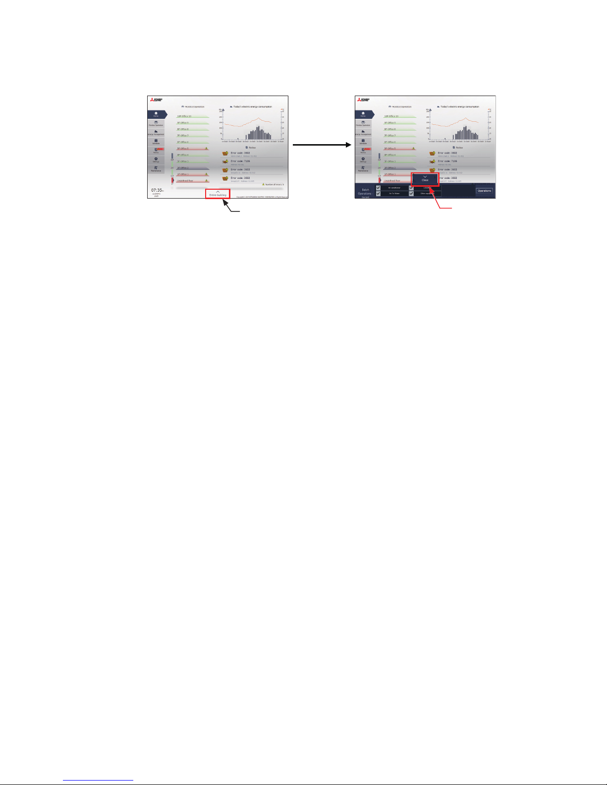
(6) Selecting all groups in the entire building
(1) In the Home screen, click [Entire building].
To cancel all group selections, click [Close] in the taskbar.
Close
Entire building
Page 18
18
WT07982X03
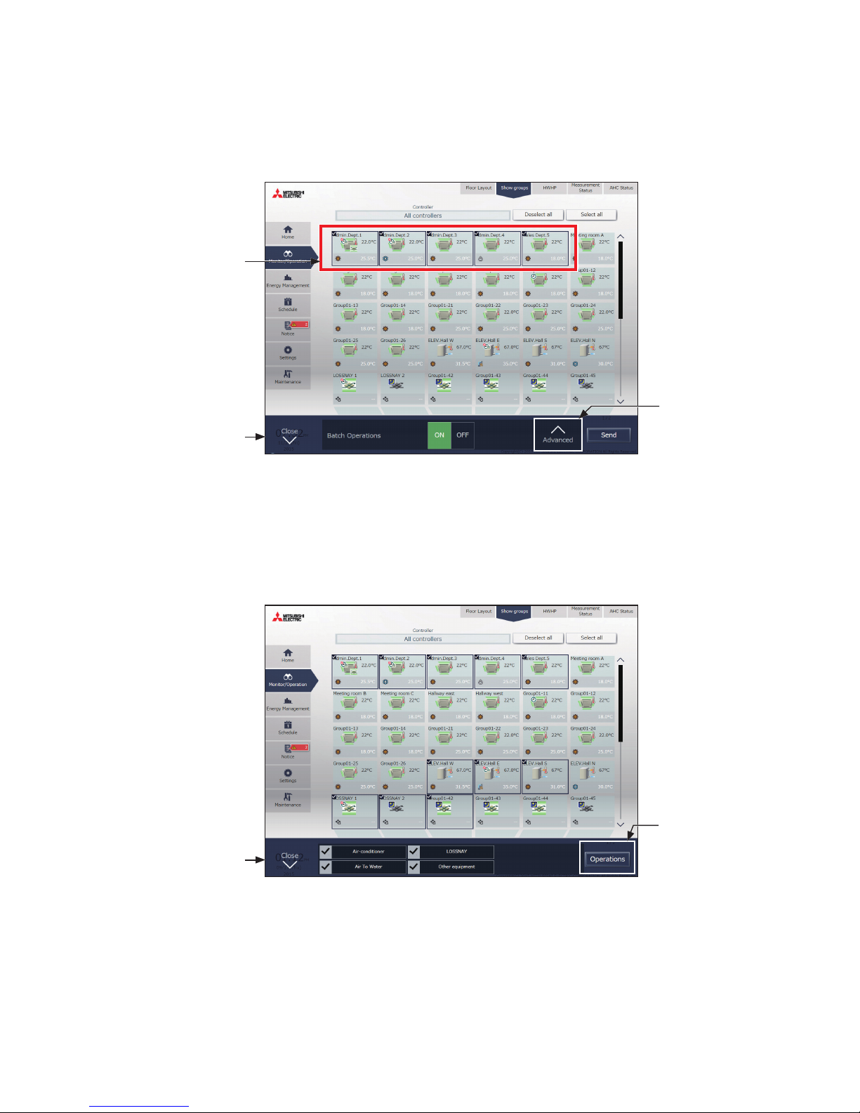
[2] Selecting equipment type
(1) When the equipment types of all selected groups are the same
Selecting the group icons to operate and clicking [Advanced] in the taskbar will bring up the operation settings
screen for the selected groups.
Refer to section 3-1-5 “Operation settings screen” for details about the advanced settings.
Note: [ON] and [OFF] operations can be performed on the taskbar for the selected unit groups.
(2) When the equipment types of the selected groups are different
Selecting the group icons to operate will bring up the equipment type selection options in the taskbar.
Select an equipment type, and click [Operations] to display the operation settings screen.
Refer to section 3-1-5 “Operation settings screen” for details about the advanced settings.
Note: When two or more equipment types are selected, only the [ON/OFF] and [Schedule] settings can be configured.
Note: [Other equipment] in the taskbar indicates general equipment.
Taskbar
Selecting groups of
the same equipment
type
Advanced settings
Taskbar
Operations
Click to operate all
groups of the selected
equipment type at
once.
Page 19
19
WT07982X03
3-1-5. Operation settings screen
On the screen under the [Monitor/Operation] menu, selecting the group icon and touching [Operate] (click [Advanced]
on the Integrated Centralized Control Web) will bring up the operation settings screen for the selected group. The
current operation conditions will appear.
Change necessary operation settings, and then touch [OK] (click [Send] on the Integrated Centralized Control
Web) to save the settings. Touch [Cancel] (click [Close] on the Integrated Centralized Control Web) to return to the
previous screen without making any changes.
Note: When the setting is changed from other controllers, the operation conditions shown on the screen will not be updated while
the screen is open.
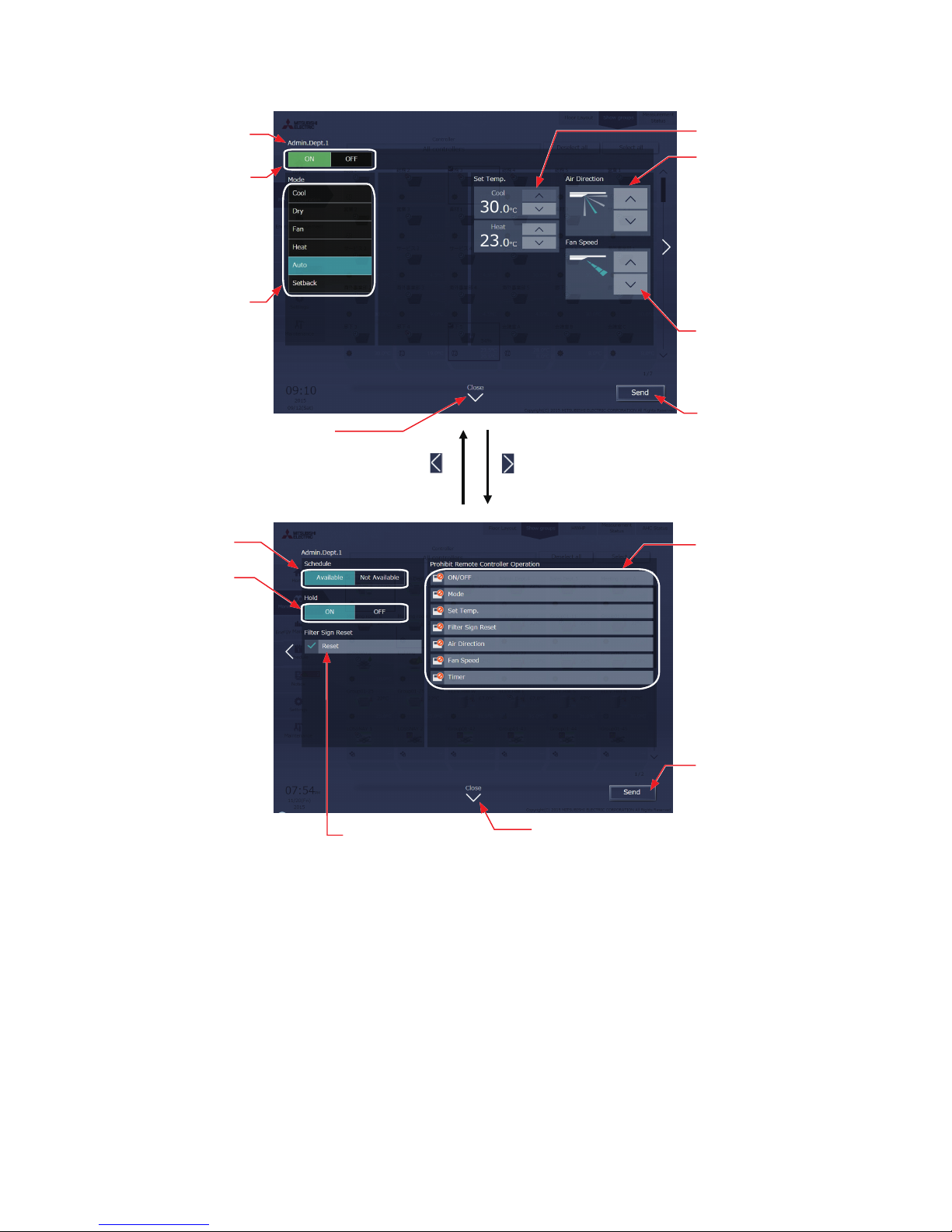
3-1-5-1. LCD
1st page
2nd page
Note: The Setback mode can be selected on the AE-200A/AE-50A, but not on the AE-200E/AE-50E.
Note: The Hold function can be used on the AE-200A/AE-50A, but not on the AE-200E/AE-50E.
Group icon
Group name
ON/OFF
Operation mode
Set temperature
Touch to go to the next
page.
Floor name or block name
Cancel
Touch to return to the
previous screen without
making any changes.
OK
Touch to reflect the changes
made.
Air Direction
Fan Speed
Prohibit Remote Controller
Schedule
Touch to go to the previous
page.
Hold
Filter Sign
Page 20
20
WT07982X03
3-1-5-2. Integrated Centralized Control Web
Note: The Setback mode can be selected on the AE-200A/AE-50A, but not on the AE-200E/AE-50E.
Note: The Hold function can be used on the AE-200A/AE-50A, but not on the AE-200E/AE-50E.
Set temperature
Close
Click to close the settings
screen without making any
changes.
Send
Click to reflect the
changes made.
Close
Click to close the settings
screen without making any
changes.
Filter Sign Reset
Click to reset the
filter sign.
Group name
ON/OFF
Operation mode
Hold
Schedule
Prohibit Remote
Controller Operation
Air Direction
Fan Speed
Send
Click to reflect the changes
made.
Page 21
21
WT07982X03
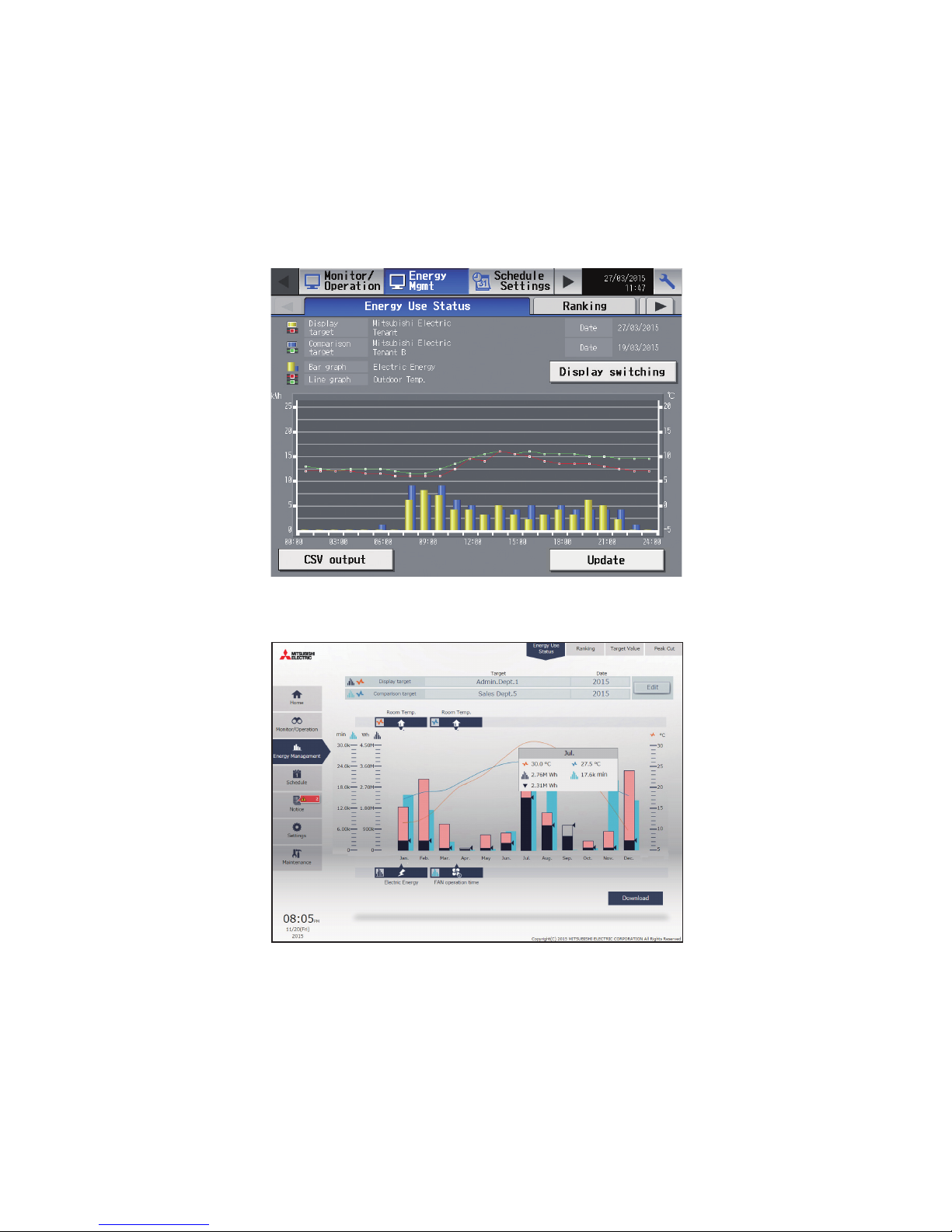
3-2. Energy Management
Only the outline of energy management function is given in this manual. For details on how to use the function, refer
to the AE-200/AE-50 Instruction Book (Detailed operations) or the AE-200/AE-50/EW-50 Instruction Book (Integrated
Centralized Control Web).
3-2-1. Energy Use Status
On the [Energy Use Status] screen, the energy-control-related status, such as electric energy consumption,
operation time, and outdoor temperature, can be displayed in a graph.
3-2-1-1. LCD
3-2-1-2. Integrated Centralized Control Web
Page 22
22
WT07982X03
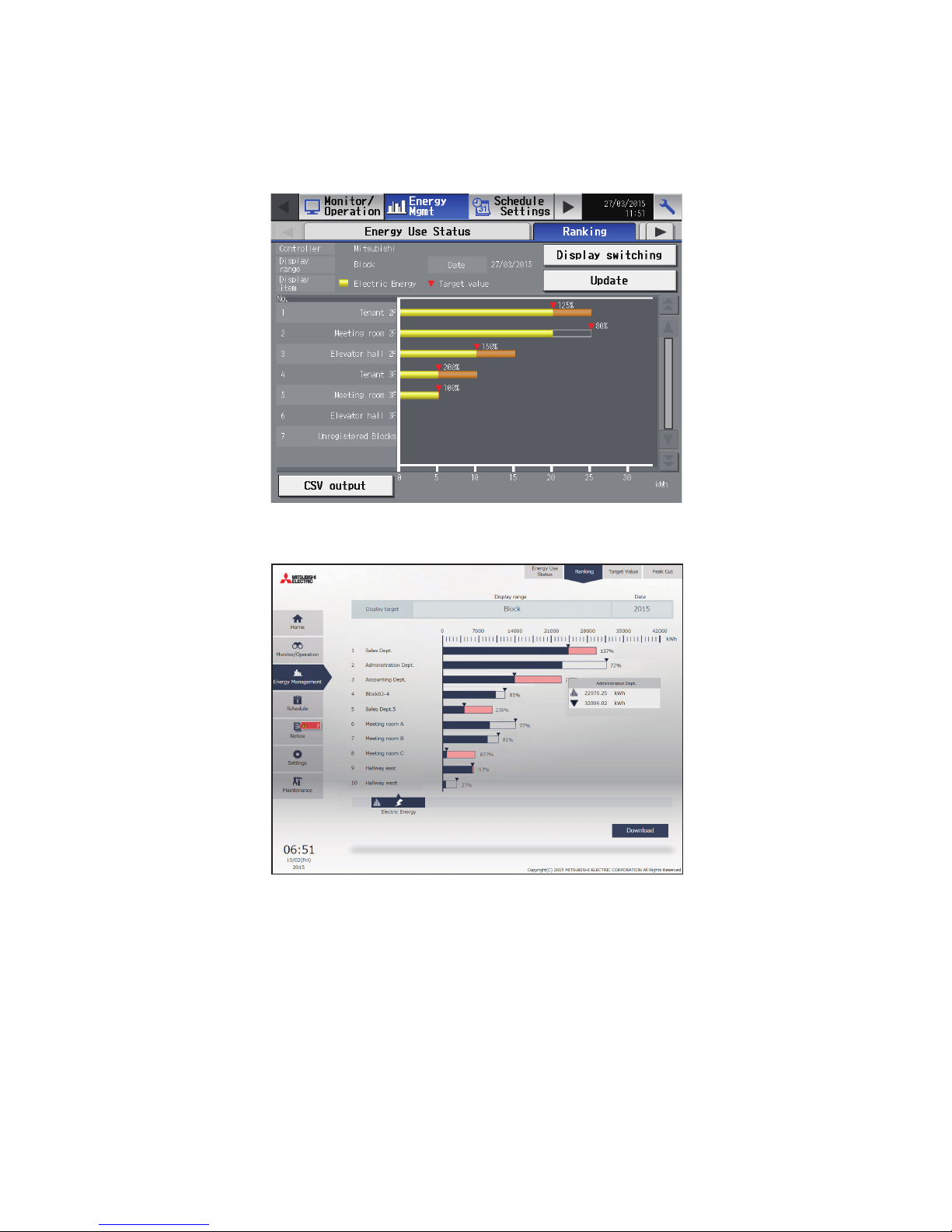
3-2-2. Ranking
On the Ranking screen, the rankings in electric energy consumption, fan operation time, and Thermo-ON time (Total/
Cool/Heat) of given indoor units can be displayed per block, group, and unit address in descending order in the bar
graph.
3-2-2-1. LCD
3-2-2-2. Integrated Centralized Control Web
Page 23
23
WT07982X03
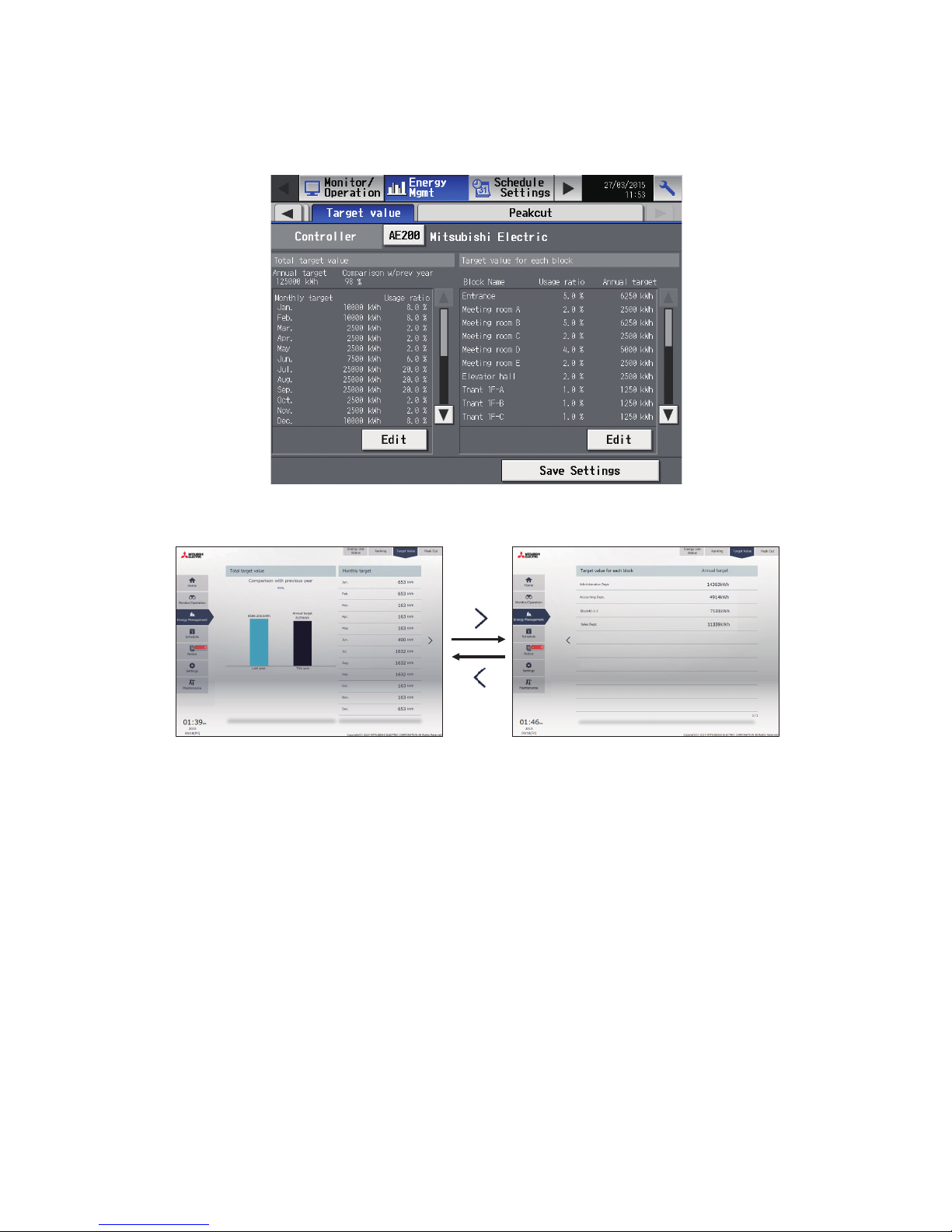
3-2-3. Target value
This section explains how to set the target electric energy consumption values for the entire system for the current
year, each month, each day of the week, and each block.
3-2-3-1. LCD
3-2-3-2. Integrated Centralized Control Web
Note: Target values can only be displayed on the Integrated Centralized Control Web.
Page 24
24
WT07982X03
3-3. Schedule
Weekly (5 types), annual (5 types), and current day scheduling are available. Schedules can be set for each group,
each floor, each block, or all groups.
Important
● When one or more AE-50/EW-50 controllers are connected, the schedule settings must be made with the AE-50/EW-50
properly connected to ensure proper settings.
● Set the [Schedule] setting on the operation settings screen to [Available] to enable the scheduled events. (Refer to section
3-1-5 “Operation settings screen” for details.)
Schedule setting example
3
10
17
24
31
4
11
18
25
5
12
19
26
6
13
20
27
7
14
21
28
1
8
15
22
29
2
9
16
23
30
3
10
17
24
4
11
18
25
5
12
19
26
6
13
20
27
7
14
21
28
1
8
15
22
29
2
9
16
23
30
31
3
10
17
24
31
2
9
16
23
30
4
11
18
25
5
12
19
26
6
13
20
27
7
14
21
28
1
8
15
22
29
Days that Weekly Schedule runs
Days that Annual Schedule runs
Days that Today's Schedule runs
Jan Feb Mar Apr May Jun Jul Aug Sep Oct Nov Dec
Weekly
schedule 1
(special)
Note: The figure above shows the setting example of weekly schedules where the date period for each Weekly Schedule is set to
the followings.
Weekly Schedule 1: Aug 1 - Aug 20
Weekly Schedule 2: Jun 16 - Sep 15
Weekly Schedule 3: Sep 16 - Nov 15
Weekly Schedule 4: Nov 16 - Mar 15
Weekly Schedule 5: Mar 16 - Jun 15
Note: When any of the Weekly Schedules 1, 2, 3, 4, and 5 overlap, the schedule with the lower number takes priority. For example,
Weekly Schedule 1 takes precedence over Weekly Schedule 2.
SUN MON TUE WED THU FRI SAT
FRI SAT
FRI SAT
Aug
Group 1
Aug
Group 2
Aug
Group 3
Weekly schedule 2
(summer)
Weekly
schedule 4
(winter)
Weekly
schedule 4
(winter)
Weekly schedule 5
(spring)
Weekly schedule 3
(autumn)
Page 25

25
WT07982X03
Note: When the schedules overlap, schedule with the highest priority will run as shown below.
Priority High
Today’s schedule
Schedules can be set for the current day without modifying the
weekly or annual schedules.
Annual schedule
Different schedules can be set for public holidays or summer
vacation.
Weekly schedule 1
Schedules can be set for each day of the week.
Weekly schedule 2
Schedules can be set for each day of the week.
Weekly schedule 3
Schedules can be set for each day of the week.
Weekly schedule 4
Schedules can be set for each day of the week.
Weekly schedule 5
Schedules can be set for each day of the week.
Low
Page 26
26
WT07982X03
3-3-1. Weekly Schedule
Schedules can be set for each day of the week.
Note: When today’s schedule and weekly schedule are set for the same day, today’s schedule settings take precedence over
weekly schedule settings.
Note: When the “Schedule: Season setting” setting is set to [Available] (default setting), weekly schedule date range settings can
be configured. Be sure to set the “Schedule: Season setting” setting ([Available] or [Not Available]) with the AE-200. (Do not
set with the expansion controller (AE-50/EW-50).) For the “Schedule: Season setting” setting, refer to the Instruction Book
(Initial Settings).
3-3-1-1. LCD
Touch [Schedule Settings] in the menu bar, and then touch [Weekly1], [Weekly2], [Weekly3], [Weekly4], or [Weekly5].
On the Weekly Schedule settings screen, schedules can be set for each day of the week.
[1] Setting the date periods
(1) Touch the “Season Settings” button on the [Floor] or
[Block] display.
Note: For the Integrated Centralized Control Web, the setting
is made on the “Date range setting” screen.
(2) Enter the date periods in which each weekly schedule
will be effective.
Touch the “Enabled/Disabled” buttons on the left side to
enable or disable each weekly schedule.
: Enabled
: Disabled (default)
Note: When any of the Weekly Schedules 1, 2, 3, 4, and 5
overlap, the schedule with the lower number takes
priority. For example, Weekly Schedule 1 takes
precedence over Weekly Schedule 2.
Note: The date period over the next year (such as 11/01 -
03/31) can be set.
Note: The settings made on this screen on the AE-200 will be
reflected to the AE-50/EW-50.
[2] Selecting a target to which the schedule will be applied
(1) On the [Floor] or [Block] display, select a group(s),
block(s), or floor(s) to which the schedule will be applied.
(Refer to 3-1-4 “Selecting the icons of the groups to be
operated” for details.)
Season Settings
Enabled/Disabled
Next page
Previous page
Page 27
27
WT07982X03
(2) If different equipment types exist together, a screen to
select an equipment type will appear.
Touch one of the equipment types to set the schedule.
(3) A [Schedule Settings] screen will appear.
To create a schedule for the given block from scratch,
touch [New settings] and touch [OK].
To create a schedule based on the existing setting of
another group, touch [Based on the following group
settings], select the name of the group whose schedule
is to be based on, and touch [OK]. The contents of the
schedule that have been set for the selected group will
appear in the “Contents of Schedule” section on the
screen that will appear next.
[3] Selecting a day of the week
(1) Touch the day to set the schedule.
The icons of the events that have been set for the
selected group will appear in the “Contents of Schedule”
section.
Icons in the simplified display area
: ON
: OFF
: Other scheduled events
Note: To delete each scheduled events, touch the “Delete”
button in the row of the schedule to be deleted.
Simplified display area
Day-of-the-week selection
Contents of Schedule
Delete
Simplified display area
Page 28
28
WT07982X03
[4] Setting the contents of the schedule
(1) Touch the row of the schedule to be set in the “Contents of Schedule” section to display the schedule settings
screen.
Set the start time to apply to the schedule, set the operations to be scheduled, and then touch [OK].
Note: If [Optimized Start] is selected, the operation mode and the set temperature need to be set as well.
To copy the schedule settings between groups, see [7] below.
To copy the schedule settings between days of the week, see [5] below.
Note: About Optimized Start function
9:00
8:45
9:00
8:40
26ºC
24ºC
• If [Optimized Start] is selected, the operation mode and the set temperature need to be set as well. The Optimized Start
function will start the units 5 to 60 minutes prior to the scheduled start time to reach the set temperature at the scheduled
start time, based on the operation data in the past. (When the units start the first time after a power reset, the units will
start operation 30 minutes before the scheduled start time.)
• [Optimized Start] can be selected only for the air conditioning unit groups.
• If the room temperature is measured by the return air temperature sensor on the air conditioning unit, the measured value
may not be an accurate representation of the temperature in the room. The temperature shown may be higher than the
actual temperature especially when the unit is stopped during the Heat mode. When this is the case, use an external
temperature sensor (PAC-SE40TSA) or remote controller sensor to measure the room temperature.
• If [Optimized Start] is selected and the [Prohibit Remote Controller] setting is set to Prohibit or Permit at the same time,
the operations from the remote controllers will be prohibited or permitted at the scheduled start time.
1st page (Air conditioning unit group)
Scheduled start time
Schedule settings
OK
2nd page (Air conditioning unit group)
Scheduled start time
Schedule settings
OK
Cool ON
Operation mode: Cool
Start time: 9:00
Set temperature: 26ºC
Room
temperature
Heat ON
Operation mode: Heat
Start time: 9:00
Set temperature: 24ºC
Room
temperature
Page 29

29
WT07982X03
[5] Copying a schedule to another day of the week
(1) To copy the schedule settings of a day to the schedule
settings for another day of the week, select the day
whose schedule settings are to be copied, touch [Copy],
select the day to which the copied schedule settings are
to be pasted, and touch [Paste].
Note: To delete each scheduled events, touch the “Delete”
button in the row of the schedule to be deleted.
[6] Saving the schedules
(1) To undo the changes made, touch [Cancel] before
saving the schedules.
After completing the settings, touch [OK] to save the
schedules.
Note: To delete each scheduled events, touch the “Delete”
button in the row of the schedule to be deleted.
[7] Copying a schedule to another group
(1) To copy the schedule settings of a group to the schedule
settings for another group, select the group whose
schedule settings are to be copied, touch [Copy], select
the group to which the copied schedule settings are to
be pasted, and touch [Paste].
Note: Schedules of a group cannot be copied to a different
type of group. For example, the schedules of an
air conditioning unit group cannot be copied to the
schedules for a LOSSNAY unit group.
Note: The operation mode and set temperature may not
be copied because the available operation modes or
operable set temperature range differ among the units.
Copy
Paste
Delete
Day of the week selection
OK
Delete
Cancel
Copy
Paste
Page 30

30
WT07982X03
3-3-1-2. Integrated Centralized Control Web
[1] Selecting a target to which the schedule will be applied
In the Floor Layout screen or group list, select a group icon(s) to which the schedule will be applied, and click
[Schedule settings]. A screen to set a schedule for the selected group(s) will appear.
Refer to section 3-1-4 “Selecting the icons of the groups to be operated” for how to select group icons.
(1) Select [HWHP] to set the schedule for HWHP (CAHV, CRHV) units, or select [Show groups] to set the
schedule for other equipment.
(2) Select a group icon(s) to which the schedule will be
applied, and click [Schedule settings] in the taskbar.
(3) If different equipment types exist together, a screen
to select an equipment type will appear.
Select one of the equipment types to set the
schedule.
(4) Select a setting method.
(A) To create a new schedule or to edit an existing schedule, click [Edit schedule contents] and click [OK].
(B) To create a schedule based on the existing setting of other group, select [Create based on other group],
select the group whose schedule is to be based on, and click [OK]. The contents of the schedule that
have been set for the selected group will appear on the screen that will appear next.
Note: If the group whose schedule is to be based on has no schedule settings, no contents of the schedule will appear on the
screen that will appear next.
Schedule (Floor Layout)
Schedule (Group list)
Schedule
settings
Schedule settings
(A) Creating newly or editing (B) Creating based on the setting of other group
Edit schedule contents
Create based on other
group
Select the group whose
schedule is to be based
on.
Page 31

31
WT07982X03
[2] Setting the date range for each schedule
Five types of weekly schedules can be set. (One year is divided into the maximum of five periods.)
Note: This setting is “Season Settings” on the LCD.
Note: The weekly schedule date ranges are set for each centralized controller (AE-200/AE-50/EW-50). When the weekly schedule
date ranges are set with Integrated Centralized Control Web, the same settings will be sent to all the centralized controllers
that are control targets of Integrated Centralized Control Web.
(1) In the Schedule settings screen (Month or Week display), click [Weekly schedule].
(2) In the Weekly schedule settings screen, click [Date range].
(3) In the date range settings screen, enter the date ranges in which each weekly schedule (Weekly 1 to 5) will
be effective.
Note: On the date range setting screen, check the checkbox ( ) to disable the date range setting of the checked weekly schedule.
Note: If the “Schedule: Season setting” setting is set to “Not Available” in the initial settings, the date range settings cannot be used.
For initial settings, refer to the Instruction Book (Initial Settings).
Weekly schedule
Schedule settings (Month)
Weekly schedule settings
Display switching
Switches between
Month and Week.
Date range
Schedule settings (Week)
Display switching
Switches between
Month and Week.
Date range setting
disabled
Weekly schedule
Date range setting
Page 32

32
WT07982X03
[3] Selecting a day of the week
Schedules can be set for each day of the week for each weekly schedule (Weekly 1 to 5).
(1) In the Schedule settings screen, select one of the weekly schedule (Weekly 1 to 5).
(2) Click the day to set the schedule.
A screen to edit the schedules of the selected weekly schedule and the selected day of the week will
appear.
[4] Creating or changing the schedule contents
(1) In the Edit schedule settings screen, click [Add] to create a new schedule, or click [Edit] to change an
existing schedule. A schedule contents settings screen will appear.
Weekly schedule
Edit schedule settings
Weekly 1–5
Select the weekly
schedule to set the
schedule.
Day-of-the-week
selection
Select the day to
set the schedule.
Simplified display
The simple schedule contents for
each day of the week will appear.
Day of the week
The selected day
of the week will
appear.
Schedule contents
Simplified display
The simple schedule contents will
appear.
Weekly 1–5
The
selected
weekly
schedule
will appear.
Edit
Click to change an existing schedule
contents.
Add
Click to create a new schedule.
Edit schedule settings
Page 33

33
WT07982X03
(2) In the schedule contents settings screen, set the start time to apply to the schedule, set the operations to
be scheduled, and then click [OK].
If [Optimized Start] is selected, the operation mode and the set temperature need to be set as well.
(3) After all schedule settings are completed, click [OK] on the Edit schedule settings screen.
Note: When setting a schedule for a block or all groups collectively, all operation modes are available for selection, but the available
operation modes depend on the unit model. The units will not operate in the selected mode not supported by the units.
Note: No need to set schedules for all operations. Set one or more necessary operations.
Note: The operation items that will appear on the screen vary, depending on the equipment type.
Note: For details about settings of each operation, refer to section 3-1-5 “Operation settings screen”.
Schedule contents settings (2/2)
Scheduled
start time
Cancel
Click to undo the changes made
and close the settings screen.
OK
Click to confirm
the settings.
Cancel
Click to cancel the settings
and close the settings screen.
Scheduled
start time
OK
Click to
confirm the
settings.
Delete
Click to
delete the
settings.
Delete
Click to delete
the settings.
Schedule contents settings (1/2)
Cancel
Click to undo the changes
made and close the Edit
schedule settings screen.
OK
Click to confirm the settings.
Schedule settings
Page 34

34
WT07982X03
[5] Saving the schedules
(1) After the schedule settings are completed, click [Send] on the Schedule settings screen to send and save
the settings to the centralized controllers.
To undo the changes made, click [Cancel].
Note: Clicking [Send] will send the schedule settings to the centralized controllers (AE-200/AE-50/EW-50). It may take a few minutes
to complete the transmission, depending on the volume of the schedule contents.
[6] Copying existing settings of other group
The schedule settings can be copied among groups.
(1) In the Floor Layout screen or group list, select the group whose schedule settings are to be copied, and
then click [Copy] in the taskbar.
(2) The schedule contents of the selected group will be copied, and the group icon will appear with an orange
frame.
(3) Select the group to which the copied schedule settings are to be pasted, and click [Paste].
The name of the group whose schedule settings have been copied appears under the [Copy] button.
Cancel
Click to undo the changes
made and close the Schedule
settings screen.
Send
Click to save the settings.
Schedule settings
Copy
Click to copy the
schedule contents of
the selected group.
Group icon
Select the group
whose schedule
settings are to be
copied.
Procedure (1)
Procedure (2)
Copied
The group icon
will appear
with an orange
frame.
Name of the group
whose schedule
settings are copied
Paste
Click to paste the
copied settings.
Procedure (3)
Group icon
Select the group
to which the
copied schedule
settings are to be
pasted
•Floor Layout screen
Page 35

35
WT07982X03
Note: Schedules of a group cannot be copied to a different type of group.
[7] Creating a schedule based on existing settings of other day of the week
When setting schedules for each day of the week for weekly schedule, the schedule settings can be created based
on existing settings of other day of the week.
(1) In the Edit schedule settings screen, click [Based on...].
(2) In the [Based on...] screen, select the pattern or the day of the week whose schedule is to be based on.
(3) The contents of the schedule that have been set for the selected pattern or the day of the week will appear
in the Edit schedule settings screen.
(4) Add or change the schedule contents, if necessary.
Copy
Click to copy the
schedule contents of
the selected group.
Group icon
Select the group
whose schedule
settings are to be
copied.
Procedure (1)
Procedure (2)
Copied
The group icon
will appear
with an orange
frame.
Name of the group
whose schedule
settings are copied
Paste
Click to paste the
copied settings.
Procedure (3)
Group icon
Select the group
to which the
copied schedule
settings are to be
pasted
•Group list
•Weekly schedule
Day of
the week
to set the
schedule
Day of the week
Select the day of the
week whose schedule is
to be based on.
Day-of-the-week selection
Schedule contents
The contents of the
schedule that have
been set for the
selected day of the
week will appear.
Edit
Click to edit the
schedule contents.
Edit schedule settings (weekly schedule settings)
Based on existing settings
of other day of the week
Edit schedule settings (weekly schedule settings)
Add
Click to add the schedule
contents.
Page 36

36
WT07982X03
3-3-2. Annual Schedule
On the Annual Schedule settings screen, schedules can be set for public holidays or summer vacation.
Up to five operation patterns (Pattern A through E) can be set for the 24 months including the current month, and
total of 50 days can be allocated to the patterns.
Note: When today’s schedule and annual schedule are set for the same day, today’s schedule settings take precedence over
annual schedule settings.
3-3-2-1. LCD
Touch [Schedule Settings] in the menu bar, and then touch [Annual].
[1] Selecting a target to which the schedule will be applied
(1) On the [Floor] or [Block] display, select a group(s),
block(s), or floor(s) to which the schedule will be applied.
(Refer to 3-1-4 “Selecting the icons of the groups to be
operated” for details.)
[2] Selecting a schedule pattern
(1) Touch a pattern or [Edit] to display the pattern settings
screen.
(2) Touch a pattern tab to set the schedule.
Note: To delete each scheduled events, touch the “Delete”
button in the row of the schedule to be deleted.
Edit
Pattern (A–E)
Pattern
Contents of Schedule
Delete
Page 37

37
WT07982X03
[3] Setting the contents of the schedule
(1) Touch the row of the schedule to be set in the “Contents of Schedule” section to display the schedule settings
screen.
Set the start time to apply to the schedule, set the operations to be scheduled, and then touch [OK]. (Refer to
section 3-3-1-1 [4] “Setting the contents of the schedule” for details.)
[4] Copying a schedule to another pattern
(1) To copy the schedule settings of a pattern to the
schedule settings for another pattern, select the pattern
whose schedule settings are to be copied, touch [Copy],
select the pattern to which the copied schedule settings
are to be pasted, and touch [Paste].
Note: To delete each scheduled events, touch the “Delete”
button in the row of the schedule to be deleted.
[5] Assigning schedule patterns to special dates
(1) Each schedule pattern can be assigned to the specified
dates.
The date buttons will appear with the alphabet of the
pattern that has been assigned.
Touching the date buttons toggles through the following
options: A, B, C, D, E, and blank.
To cancel the pattern assignment, select blank.
Copy
Paste
Delete
Date button
Page 38

38
WT07982X03
[6] Saving the schedules
(1) To undo the changes made, touch [Cancel] before
saving the schedules.
After completing the settings, touch [OK] to save the
schedules.
[7] Copying a schedule to another group
(1) Refer to 3-3-1-1 [7] “Copying a schedule to another group” for details.
OK
Cancel
Page 39

39
WT07982X03
3-3-2-2. Integrated Centralized Control Web
[1] Selecting a target to which the schedule will be applied
(1) In the Floor Layout screen or group list, select a group icon(s) to which the schedule will be applied.
Refer to 3-3-1-2 [1] “Selecting a target to which the schedule will be applied” for details.
[2] Selecting a schedule pattern
Up to five operation patterns can be set.
(1) In the Schedule settings screen (Month or Week display), click [Annual schedule pattern].
(2) In the pattern settings screen, select a schedule pattern to set the schedule.
(3) An Edit schedule settings screen will appear.
[3] Creating or changing the schedule contents
(1) In the Edit schedule settings screen, set the start time to apply to the schedule, set the operations to be
scheduled, and then click [OK].
Refer to 3-3-1-2 [4] “Creating or changing the schedule contents” for details.
Schedule settings (Month)
Pattern settings
Edit schedule settings (Pattern)
Annual schedule pattern
Display switching
Switches between
Month and Week.
Pattern selection
Select a pattern to
set the schedule.
Schedule
contents
Pattern to set the schedule
Simplified display
The simple schedule
contents for each
pattern will appear.
Simplified display
The simple schedule contents
for each pattern will appear.
Page 40

40
WT07982X03
[4] Allocating schedule patterns to special dates
Each schedule pattern can be allocated to the specified dates such as public holidays and summer vacation.
(1) In the Schedule settings screen (Month or Week display), click the date to set a pattern.
(2) Select the pattern to be allocated to the selected date.
[5] Saving the schedules
(1) After the schedule settings are completed, click [Send] on the Schedule settings screen to send and save
the settings to the centralized controllers.
To undo the changes made, click [Cancel].
Note: Clicking [Send] will send the schedule settings to the centralized controllers (AE-200/AE-50/EW-50). It may take a few minutes
to complete the transmission, depending on the volume of the schedule contents.
[6] Copying existing settings of other group
(1) The annual schedule settings can be copied among groups.
Refer to 3-3-1-2 [6] “Copying existing settings of other group” for details.
Schedule settings (Month)
Date
Click the date to
set a pattern.
Number of allocated
patterns
Pattern
selection
Select a pattern
to set the
schedule.
Display switching
Switches between
Month and Week.
Cancel
Click to undo the changes
made and close the Schedule
settings screen.
Send
Click to save the settings.
Schedule settings
Page 41

41
WT07982X03
[7] Creating a schedule based on existing settings of other pattern
When setting annual schedule patterns, the schedule settings can be created based on existing settings of other
pattern.
(1) In the Edit schedule settings screen, click [Based on...].
(2) In the [Based on...] screen, select the pattern or the day of the week whose schedule is to be based on.
(3) The contents of the schedule that have been set for the selected pattern or the day of the week will appear
in the Edit schedule settings screen.
(4) Add or change the schedule contents, if necessary.
•Annual schedule
Pattern
to set the
schedule
Pattern
Select the pattern
whose schedule is to be
based on.
Pattern selection
Schedule contents
The contents of the
schedule that have
been set for the
selected pattern will
appear.
Edit
Click to edit the
schedule contents.
Edit schedule settings (pattern settings)
Based on existing
settings of other pattern
Edit schedule settings (pattern settings)
Add
Click to add the schedule
contents.
Page 42

42
WT07982X03
3-3-3. Today’s Schedule
On the Today’s Schedule settings screen, schedules can be set for the current day without modifying the weekly or
annual schedules.
Note: Be sure to set the contents of schedule in a way that will not impact on the next day’s operation. For example, if Prohibit
setting of remote controller operation is made for any time such as 17: 00, Permit setting needs to be made for any time
before the date changes such as 23: 59.
3-3-3-1. LCD
Touch [Schedule Settings] in the menu bar, and then touch [Today].
[1] Selecting a target to which the schedule will be applied
(1) On the [Floor] or [Block] display, select a group(s),
block(s), or floor(s) to which the schedule will be applied.
(Refer to 3-1-4 “Selecting the icons of the groups to be
operated” for details.)
[2] Setting the contents of the schedule
(1) Touch the row of the schedule to be set in the “Contents of Schedule” section to display the schedule settings
screen.
Set the start time to apply to the schedule, set the operations to be scheduled, and then touch [OK]. (Refer to
section 3-3-1-1 [4] “Setting the contents of the schedule” for details.)
[3] Saving the schedules
To undo the changes made, touch [Cancel] before
saving the schedules.
After completing the settings, touch [OK] to save the
schedules.
Note: To delete each scheduled events, touch the “Delete”
button in the row of the schedule to be deleted.
Note: If no schedule setting is made and [OK] is touched, the
weekly or annual schedules for the same day will not be
performed.
[4] Copying a schedule to another group
(1) Refer to 3-3-1-1 [7] “Copying a schedule to another group” for details.
OK
Delete
Cancel
Page 43

43
WT07982X03
3-3-3-2. Integrated Centralized Control Web
[1] Selecting a target to which the schedule will be applied
(1) In the Floor Layout screen or group list, select a group icon(s) to which the schedule will be applied.
Refer to 3-3-1-2 [1] “Selecting a target to which the schedule will be applied” for details.
[2] Setting or changing the contents of the schedule
(1) In the Schedule settings screen (Month or Week display), click the date of the current day.
The current day is displayed with a blue frame.
(2) Click [Today’s schedule settings].
(3) In the Edit schedule settings screen, set the start time to apply to the schedule, set the operations to be
scheduled, and then click [OK].
Refer to 3-3-1-2 [4] “Creating or changing the schedule contents” for details.
Note: In the Schedule settings screen, “Today” ( ) is displayed on the date of the current day to which Today’s
schedule is set.
[3] Saving the schedules
(1) After the schedule settings are completed, click [Send] on the Schedule settings screen to send and save
the settings to the centralized controllers.
To undo the changes made, click [Cancel].
Note: Clicking [Send] will send the schedule settings to the centralized controllers (AE-200/AE-50/EW-50). It may take a few minutes
to complete the transmission, depending on the volume of the schedule contents.
[4] Copying existing settings of other group
(1) The today’s schedule settings can be copied among groups.
Refer to 3-3-1-2 [6] “Copying existing settings of other group” for details.
Schedule settings (Month) Edit schedule settings (Today)
Current day
Click the current day.
Display switching
Switches between
Month and Week.
Today’s schedule settings
Cancel
Click to undo the changes
made and close the Schedule
settings screen.
Send
Click to save the settings.
Schedule settings
Today’s schedule set
Page 44

44
WT07982X03
3-4. Status List
3-4-1. Malfunction List
3-4-1-1. LCD
Touch [Status List] in the menu bar, and then touch [Malfunction].
A list of units that are currently malfunctioning will appear.
Note: The [Controller] setting will appear (only on the AE-200’s LCD) when the [System Exp] setting on the [Unit Info.] screen is set
to [Expand]. Switch the [Controller] setting between [AE200] and [Exp1] through [Exp4] to display the list for each AE-200,
AE-50, and EW-50 individually.
Note: When an error occurs, check the address of the unit in error, error code and its definition, and then contact your dealer.
Item Description
Floor name or block name
The name of the floor or the block that the unit in error belongs to will appear.
Note: This area will be blank if the unit in error is a unit such as an outdoor unit or a system
controller.
Note: This area will be blank if the unit in error is a unit that does not belong to any block or
floor.
Group name
The name of the group that the unit in error belongs to will appear.
Note: This area will be blank if the unit in error is a unit such as an outdoor unit or a system
controller.
Unit address
The address of the unit in error will appear.
Note: When [1], [2], [3], or [4] is selected as [Controller], AE-50/EW-50 No. and unit address
will appear. (When the AE-50/EW-50 No. is 1 and the unit address is 012, “1-012” will
appear.)
Number of units in error The number of malfunctioning units will appear.
Error code
The error code that corresponds to the error will appear.
Touch the error code to display the definition.
All Reset
Touch to reset all errors at once.
Note: The units whose error has been reset will stop.
Note: When the errors are reset, the units that are not in error may stop. Refer to the
Instruction Book (Detailed operations) for details.
Controller
Select [AE] to display the list
for AE-200, and select [1],
[2], [3], or [4] to display the
list for each AE-50/EW-50.
Floor name or block name
Group name
Unit address
Number of units in error
Error code
All Reset
Touch to reset all errors at
once.
Number of units whose
filter sign is turned on
Page 45

45
WT07982X03
3-4-1-2. Integrated Centralized Control Web
Click [Notice] in the menu, and then click [Error List] to access the Error List screen.
A list of units that are currently malfunctioning will appear.
Note: When an error occurs, check the address of the unit in error, error code and its definition, and then contact your dealer.
Item Description
Controller Display target units can be narrowed down by selecting a centralized controller.
Group name
The name of the group that the unit in error belongs to will appear.
Note: The group name will not be displayed if the unit in error is a unit such as an outdoor
unit or a system controller.
Unit address The centralized controller No. and address of the unit in error will appear.
Error code
The error code that corresponds to the error will appear.
Click the error code to display the definition.
Reset All
Click to reset the errors at once.
Note: The units whose error has been reset will stop.
Note: Only the errors of the centralized controller selected in [Controller] will be reset.
* The units that are not in error may stop when errors are reset. Refer to the AE-200/AE-50 Instruction Book (Detailed operations) for details.
Group name
Unit address
Reset All
Controller
Error code
Page 46

46
WT07982X03
3-4-2. Filter Sign List
3-4-2-1. LCD
A list of units whose filter sign is turned on can be displayed.
Touch [Status List] in the menu bar, and then touch [Filter Sign].
Note: The [Controller] setting will appear (only on the AE-200’s LCD) when the [System Exp] setting on the [Unit Info.] screen is set
to [Expand]. Switch the [Controller] setting between [AE200] and [Exp1] through [Exp4] to display the list for each AE-200,
AE-50, and EW-50 individually.
Item Description
Number of units whose filter sign
is turned on
The number of units whose filter sign is currently turned on will appear.
Floor name or block name
The name of the floor or the block that the unit whose filter sign is turned on belongs to will
appear.
Note: This area will be blank if the unit whose filter sign is turned on does not belong to any
floor or block.
Group name The name of the group that the unit belongs to will appear.
Unit address
The address of the unit whose filter sign is turned on will appear.
Note: When [1], [2], [3], or [4] is selected as [Controller], AE-50/EW-50 No. and unit address
will appear. (Example: 1-012)
Reset
Touch to reset each filter sign.
Note: Reset the filter sign after cleaning the filter.
Note: After the filter sign is reset, it takes up to an hour to clear the filter sign display on
the local remote controllers. (When the filter sign is reset from the local remote
controllers, it takes up to an hour to clear the filter sign display on the AE-200/AE-50’s
LCD.)
All Reset
Touch to reset all filter signs at once.
Note: Reset the filter signs after cleaning the filters.
Note: After the filter signs are reset, it takes up to an hour to clear the filter sign display on
the local remote controllers. (When the filter signs are reset from the local remote
controllers, it takes up to an hour to clear the filter sign display on the AE-200/AE-50’s
LCD.)
Controller
Select [AE] to display the list
for AE-200, and select [1],
[2], [3], or [4] to display the
list for each AE-50/EW-50.
Floor name or block name
Group Name
Unit address
Number of units whose
filter sign is turned on
Reset
Touch to reset the filter sign.
All Reset
Touch to reset all filter signs
at once.
Page 47

47
WT07982X03
3-4-2-2. Integrated Centralized Control Web
A list of units whose filter sign is turned on can be displayed.
Click [Notice] in the menu, and then click [Filter sign] to access the Filter sign screen.
Item Description
Controller Display target unit groups can be narrowed down by selecting a centralized controller.
Group name The name of the group that the unit whose filter sign is turned on belongs to will appear.
Unit address
The centralized controller No. and address of the unit whose filter sign is turned on will
appear.
Reset
Click to reset the filter sign of the group that the unit whose filter sign is turned on belongs
to.
Note: Reset the filter sign after cleaning the filter.
Reset All
Click to reset all filter signs of the centralized controller selected in [Controller] at once.
Note: Reset the filter sign after cleaning the filter.
Note: After the filter signs are reset, it takes up to an hour to clear the filter sign display on
the local remote controllers.
When the filter signs are reset from the local remote controllers, it takes up to an hour
to clear the filter sign display on this screen.
Group name
Unit address
Reset All
Controller
Reset
Page 48

48
WT07982X03
3-5. Malfunction Log
3-5-1. Unit Error/Communication Error
3-5-1-1. LCD
Touch [Log] in the menu bar, and then touch [Unit Error] to display unit errors, or touch [Communication Error] to
display M-NET communication errors.
Note: The [Controller] setting will appear (only on the AE-200’s LCD) when the [System Exp] setting on the [Unit Info.] screen is set
to [Expand]. Switch the [Controller] setting between [AE200] and [Exp1] through [Exp4] to display the log for each AE-200,
AE-50, and EW-50 individually.
Note: If there is no error occurred, no error log will appear.
Item Description
Unit Error
Touch to display the unit error log.
Note: The latest 64 unit errors will appear for each AE-200/AE-50/EW-50.
Communication Error
Touch to display the M-NET communication error log.
Note: The latest 64 communication errors will appear for each AE-200/AE-50/EW-50.
Clear Log Touch to clear the error log.
Error occurrence date and time The date and time when the error occurred will appear.
Error source unit address
The address of the unit in error will appear.
Note: When [1], [2], [3], or [4] is selected as [Controller], AE-50/EW-50 No. and unit address
will appear. (Example: 1-012)
Error detection unit address
The address of the unit that detected the error will appear.
Note: When [1], [2], [3], or [4] is selected as [Controller], AE-50/EW-50 No. and unit address
will appear. (Example: 1-012)
Error recovery date and time The date and time when the error recovered will appear.
Error code
The error code that corresponds to the error will appear.
Touch the error code to display the definition.
Controller
Select [AE] to display the log
for AE-200, and select [1],
[2], [3], or [4] to display the
log for each AE-50/EW-50.
Unit Error
Touch to display the unit
error log.
Error occurrence date and
time
Error source unit address
Error detection unit
address
Communication Error
Touch to display the M-NET
communication error log.
Error recovery date and
time
Error code
Clear Log
Touch to clear the error log.
Page 49

49
WT07982X03
3-5-1-2. Integrated Centralized Control Web
Click [Notice] in the menu, and then click [Unit error log] to access the Unit error log screen.
Note: The latest 64 unit errors will appear for each AE-200/AE-50/EW-50.
Note: Unit errors of all AE-200/AE-50/EW-50 controllers will appear in a list.
Item Description
Controller Display target error log can be narrowed down by selecting a centralized controller.
Error occurrence date and
time
The date and time when the error occurred will appear.
Error recovery date and time
The date and time when the error was resolved will appear.
Error code
The error code that corresponds to the error will appear.
Click the error code to display the definition.
Error source unit address The centralized controller No. and address of the unit in error will appear.
Error detection unit address The address of the unit that detected the error will appear.
Clear log Click to clear the displayed unit error log of the centralized controller selected in [Controller].
Group name
Error source unit address
Clear log
Controller
Error code
Error detection unit
address
Error occurrence date and
time
Error recovery date and
time
Page 50

50
WT07982X03
4. Practical operations
4-1. Cleaning the touch panel
(1)
Touch [ ] to display the login window.
(2) On the Login window, touch the “Touch-panel-cleaning”
button.
(3) Clean the touch panel with a soft dry cloth, a well-wrung
cloth that has been soaked in water with mild detergent,
or a cloth dampened with ethanol.
Note: Do not use acidic, alkaline, or organic solvents.
(4) After cleaning, touch the squares with numbers from 1 to 4. The screen will return to the previous screen.
Note: The squares will change to gray when touched.
Touch-panel-cleaning
Page 51

51
WT07982X03
5. Initial startup settings
5-1. Initial startup setting procedures
5-1-1. AE-200 initial start-up for a system without connection to an AE-50/EW-50
controller
(1) After the power is turned on, a language selection screen will
appear.
Select the language to be used for display, and then touch [OK].
Note: It will take approximately one minute for the display to appear
after the power is turned on.
Note: Do not touch the LCD before any settings screen appears.
Note: Once the initial settings have been made, [Monitor/Operation]
screen will appear after the power is turned on.
(2) The [Date and time] screen will appear.
Referring to section 5-2-3, set the current date, current time,
and daylight saving time, and then touch [Save Settings].
(3) Touch the [Unit Info.] and [Unit Info. 2] tabs.
Referring to section 5-2-5, make necessary basic settings, and
then touch [Save Settings].
Note: Make sure to set the [System Exp] setting for the AE-200 to [Do
not expand].
Note: Make sure to set the [AE-200 M-NET] setting to [Use].
Unit Info.
Unit Info. 2
Page 52

52
WT07982X03
(4) Touch the right triangle button to display the [Groups] tab, and
touch it.
Referring to section 5-2-7, make group settings, and then
touch [Save Settings].
(5) Make the following settings, as required.
● Block settings (See section 5-2-8 “Blocks”.)
● Floor layout settings (See section 5-2-9 “Floor Layout”.)
(6) Touch the right triangle button to display the [Network] tab, and
touch it.
Referring to section 5-2-6, make necessary settings, and then
touch [Save Settings].
Note: When the LAN settings are changed, AE-200 will reboot, and
the step (7) below will be skipped.
(7)
Touch [ ] at the right top of the screen.
A message “Are you sure you want to return to the Monitor
/ Operation screen?” will appear. Touch [Yes] to move to the
[Monitor/Operation] screen.
Percentages of startup process completion will appear.
The initial settings are completed.
Note: When no communication errors occur, the startup process will
take about two or three minutes after the message appears.
When an error is occurring, it may take about five minutes.
(8) Open the [Date and time] screen, and touch [Save Settings] to
reflect the current date and time to each unit.
Page 53

53
WT07982X03
5-1-2. AE-200 initial start up for a system with connection to one or more
AE-50/EW-50 controllers
Note: When connecting one or more AE-50/EW-50 controllers, make sure to make network settings for the AE-50/EW-50 first, and
then make network settings for the AE-200.
[1] Settings on the AE-50
(1) After the power is turned on to the AE-50, a language selection
screen will appear.
Select the language to be used for display, and then touch [OK].
Note: It will take approximately one minute for the display to appear
after the power is turned on.
Note: Once the initial settings have been made, [Monitor/Operation]
screen will appear after the power is turned on.
(2) The [Date and time] screen will appear.
(3) Touch the right triangle button to display the [Network] tab, and
touch it.
Referring to section 5-2-6, set the AE-50’s IP address, and
then touch [Save Settings].
The AE-50 will reboot.
Note: When multiple AE-50 controllers are connected, set the IP
addresses on all AE-50.
Note: The AE-200 and AE-50’s IP addresses must have the same
network address.
<Reference: Default IP address)
AE-200 192.168.1.1
AE-50 192.168.1.211
[2] Settings on the EW-50
(1) Refer to the Instruction Book (Initial Settings) or the EW-50 Installation Manual.
[3] Settings on the AE-200
(1) After the power is turned on to the AE-200, a language
selection screen will appear.
Select the language to be used for display, and then touch [OK].
Note: It will take approximately one minute for the display to appear
after the power is turned on.
Note: Do not touch the LCD before any settings screen appears.
Note: Once the initial settings have been made, [Monitor/Operation]
screen will appear after the power is turned on.
Page 54

54
WT07982X03
(2) Touch the [Unit Info.] and [Unit Info. 2] tabs.
Referring to section 5-2-5, make necessary basic settings, and
then touch [Save Settings].
Note: Make sure to set the [System Exp] setting for the AE-200 to
[Expand].
Note: The [AE-200 Apportion] setting will appear only when the
“Charge” license has been registered.
Note: When “AE-200 M-NET” is set to [Use], “Controller” can be
switched to [AE200], [Exp1], [Exp2], or [Exp3] ([AE], [1], [2], or
[3]).
When “AE-200 M-NET” is set to [Do not use], “Controller” can
be switched to [AE200], [Exp1], [Exp2], [Exp3], or [Exp4] ([AE],
[1], [2], [3], or [4]).
Unit Info.
Unit Info. 2
(3) Touch the right triangle button to display the [Network] tab, and
touch it.
Referring to section 5-2-6, make sure that [AE200] is selected
as [Controller], set the AE-200’s IP address and subnet mask,
and then touch [Save Settings].
The AE-200 will reboot.
When the reboot process is complete, log in to the Initial
Settings menu.
Note: Refer to section 5-2-1 “Logging in to the Initial Settings menu”
for how to log in.
Note: Do not touch the LCD during the reboot.
(4) In the [Controller] section, select [1], [2], [3], or [4] to make
settings for each AE-50/EW-50.
Referring to section 5-2-6, set the IP address of each
AE-50/EW-50 that is connected to the AE-200, and M-NET
address, and then touch [Save Settings].
Page 55

55
WT07982X03
(5) Touch the [Groups] tab.
Referring to section 5-2-7, select [AE], [1], [2], [3], or [4]
in the [Controller] section, make group settings for each
AE-200/AE-50/EW-50, and then touch [Save Settings] on each
settings screen.
A message “Collecting connected equipment status data.
Please wait...” will appear.
(6) Make the following settings, as required.
● Block settings (See section 5-2-8 “Blocks”.)
● Floor layout settings (See section 5-2-9 “Floor Layout”.)
(7) Touch the [Date and time] tab.
Referring to section 5-2-3, set the current date, current time,
and daylight saving time, and then touch [Save Settings].
Note: The AE-200’s current date and time will be synchronized to
each AE-50/EW-50 and remote controllers.
(8)
Touch [ ] at the right top of the screen to move to the
[Monitor/Operation] screen.
Percentages of startup process completion will appear.
The initial settings are completed.
Note: When no communication errors occur, the startup process will
take about two or three minutes after the message appears.
When an error is occurring, it may take about five minutes.
Page 56

56
WT07982X03
5-2. Initial Settings
5-2-1. Logging in to the Initial Settings menu
(1)
Touch [ ] to display the login window.
(2) Enter the user name and the password on the keyboard
screen (See [1] “Keyboard screen”), and touch [Login].
[Initial Settings] menu screen will appear.
The table below shows the default user names,
passwords, and functions that are available for
maintenance users and building managers.
User
Default
user name
Default
password
Available functions
Maintenance user initial init All functions
Building manager administrator admin
The items to which access rights have been given on the [User
Info] screen are available.
*1 A maintenance user can specify the functions to be made available for building managers. Refer to the Instruction Book (Initial Settings)
for details.
*2 It is recommended to change the default user name and password so that the users other than the maintenance users and building
managers will not be able to change the settings.
Page 57

57
WT07982X03
[1] Keyboard screen
The entered characters will
appear here.
Touch to display the
keyboard for entering capital
alphabetic characters.
Touch to display the
keyboard for entering lower-
case alphabetic characters.
Touch to display the keyboard for
entering numeric characters and
symbols.
Arrow
Touch to move the cursor.
Delete
Touch to delete one
character to the left of the
cursor.
Cancel
Touch to undo the changes
made and return to the
previous screen.
OK
Touch to save the entered
characters and return to the
previous screen.
Page 58

58
WT07982X03
5-2-2. Locking the screen
Locking the screen prevents unauthorized users from accessing.
(1) To activate the screen lock function, set the [Screen
lock] setting to [Use] on the [Unit Info.] screen under the
[Initial Settings] menu.
If the screen lock function is activated, the screen locks
when the backlight turns off (after three minutes of not
touching the screen).
Note: The default setting is [Do not use].
Note: The screen lock function will not be activated when any
screen under the [Initial Settings] menu is open.
(2)
Touch [ ] on the login screen to lock the screen
immediately.
To unlock the screen, enter the same user name and
password used to log in.
Page 59

59
WT07982X03
5-2-3. Date and time
Touch [Initial Settings] in the menu bar, and then touch [Date and time].
Set the current date and time, and then touch [Save Settings].
Note: The date and time settings may not be accessible if logged in as a building manager.
Note: The date and time settings made on this screen will be reflected on all the units in the M-NET system, all connected
AE-50/EW-50 units, and the AE-200 units whose [Time Master/Sub] setting is set to [Sub].
Note: The date and time cannot be set on this screen if the [Time Master/Sub] setting is set to [Sub].
Note: The daylight saving time setting is required only on the AE-200.
Note: The date and time settings made on the AE-50/EW-50 unit whose [Time Master/Sub] setting is set to [Sub] will not be sent to
the other AE-50/EW-50 units.
Note: If the current time is moved forward while the scheduled operation is performed, the operation that was scheduled to take
place during the time that was skipped will not be performed.
Note: Changing the date and/or time when the charging function is in use can affect the calculation of the charges.
Note: If the system is connected to a TG-2000A, make or change the settings from the TG-2000A.
Note: When AE-50/EW-50 controller, DIDO controller (PAC-YG66DCA), AI controller (PAC-YG63MCA), or PI controller (PAC-
YG60MCA) is added to the system, set the current date and time on this screen to synchronize the date and time on the
added controller.
Note: Although date and time settings can be made on each AE-50/EW-50, the date and time synchronization from AE-200 is
performed once a day. Make the date and time settings on the AE-50/EW-50 only after the AE-50/EW-50 is replaced.
Important
● When one or more AE-50/EW-50 controllers are connected, the date and time settings must be made with the AE-50/EW-50
properly connected to ensure proper settings.
(1) Set the current date and time.
(2) To automatically adjust the daylight saving time, touch the “Daylight saving time” button. Touch the applicable
country, and then touch [OK].
Note: When not using the daylight saving time function, touch “----.”
Note: If the applicable country is not found, touch [Custom settings] at the bottom, and touch [OK]. Then, touch [Edit] to open
the screen below, and manually configure the daylight saving time setting.
Current date and time
Set the current date and
time.
Daylight saving time
Touch to set the country
to automatically adjust the
daylight saving time.
Edit
Touch to manually configure
the daylight saving time
setting.
Save Settings
Touch to save the changes
made.
Page 60

60
WT07982X03
Note
● Message that will appear when the date and time have been reset
If the power supply is cut off for a long time due to power failure or other reasons, the date and time will be reset, and the
following popup message will appear when the power is turned on next. If this message appears, set the date and time
again.
* This message will appear periodically until the date and time setting is made.
* If the controller is used without the date and time being set, the Schedule function or the Night Setback Control will not work properly.
* If the [Time Master/Sub] setting for the given controller is set to [Sub], temporarily change the setting to [Master], set the current date and
time, and then set the setting back to [Sub].
Page 61

61
WT07982X03
5-2-4. License registration for optional functions
Touch [Initial Settings] in the menu bar, and then touch [License].
Please ask your dealer for more details on the optional functions and how to purchase a license number.
Note: The current date and time settings are required for license registration. Refer to section 5-2-3 “Date and time” for date and
time settings.
Note: The license registration is required for each AE-200/AE-50/EW-50.
Note: The [Controller] setting will appear (only on the AE-200’s LCD) when the [System Exp] setting on the [Unit Info.] screen is set
to [Expand]. Switch the [Controller] setting between [AE200] and [Exp1] through [Exp4] to register licenses for each AE-200,
AE-50, and EW-50 individually.
Important
● When one or more AE-50/EW-50 controllers are connected, licenses for the AE-50/EW-50 must be registered with the
AE-50/EW-50 properly connected to ensure proper settings.
(1) In the [Selecting Optional Function] section, select the optional function to be registered. The current
availability will appear in the [Current Status] section.
(2) In the “License number entry field” button, enter the license number and touch [Register the license].
In the [Current Status] section, a word [Available] will appear.
If the registration is unsuccessful, verify that the selected optional function and the license number are correct.
Note: Alphabet “O” and “I” are not used for license number.
Controller
Select [AE] to register
licenses for AE-200, and
select [1], [2], [3], or [4] to
register licenses for each
AE-50/EW-50.
Selecting Optional
Function
Select the optional function
to be registered.
Current status
This indicates whether the
optional function is available
for use.
Serial No.
License number entry field
Register the license
Touch to register the license.
Page 62

62
WT07982X03
5-2-5. Unit Information
Touch [Initial Settings] in the menu bar, and then touch [Unit Info.] or [Unit Info. 2].
Make necessary basic system settings such as unit settings, display format, sound/brightness settings, use or nonuse of test run, and display or non-display of room temperature/humidity, and then touch [Save Settings].
Note: The Unit Information settings may not be accessible if logged in as a building manager.
Unit Info.
Unit Info. 2
[1] Unit Information
Follow the instructions below to set the unit name, unit ID, and System Expansion setting.
(1) Touch the [Name] button to display the keyboard. Enter the unit name in 40 alphanumeric or symbol characters
or less. The name entered here will be used on the screen of the software that controls multiple AE-200 units
and will also be used as a sender name in the error notification e-mail and e-mail alarm.
Note: The following characters cannot be used: <, >, &, “, or ‘
Unit Information
Set the unit name and unit
ID.
Sound and brightness
Set the sound and
brightness levels.
Display Format
Set the screen display items.
Save Settings
Touch to save the changes
made.
Air-conditioner Settings
Set the test run setting
and display option of room
temperature/humidity.
Save Settings
Touch to save the changes
made.
Page 63

63
WT07982X03
(2) Touch the [Unit ID] button to display the keyboard. Enter the unit ID in 6 figures. Use this setting to manage
the multiple unit IDs. The unit ID entered here will be used on the screen of the software that controls multiple
AE-200 units and will also be used as a sender ID in the error notification e-mail and e-mail alarm.
(3) When connecting one or more AE-50/EW-50 controllers, set the [System Exp] setting to [Expand].
Note: The [System Exp] section does not appear on this screen on the AE-50.
Note: When the [System Exp] setting is set to [Expand], make sure to make network settings for the AE-50/EW-50 controllers
on the [Network] screen. (Refer to section 5-2-6 “Network” for details.)
(4) When using an AE-200 apportioned electricity billing function or when not using an AE-200 M-NET, set the
[AE-200 M-NET] setting to [Do not use].
Note: When [Do not use] is selected, up to four AE-50/EW-50 controllers can be connected.
Note: The [AE-200 M-NET] section does not appear on this screen on the AE-50.
Note: The [AE-200 Apportion] section appears when “Charge” license is registered. To use an electricity charge apportioning
function of TG-2000A, set the [AE-200 Apportion] setting to [Do not use].
[2] Sound and brightness
(1) In the [Sound] section, select the volume (Level 0–3) of the buzzer that sounds when the screen is touched.
(Level 0: No sound)
Note: Although the change will be reflected right away, it will not be saved until [Save Settings] is touched.
(2) In the [Brightness] section, select the brightness (70%, 80%, 90%, 100%) of the screen. (The greater the
value, the brighter the brightness.)
Note: Although the change will be reflected right away, it will not be saved until [Save Settings] is touched.
[3] Display Format
(1) In the [Date] section, select the desired display format for year, month, and date.
(2) In the [Time] section, select the desired display of time format.
(3) In the [Temperature] section, select the desired temperature unit [ºC] or [ºF].
(4) In the [Language] section, select the desired display language.
(5) In the [Pressure unit] section, select [MPa], [PSI], or [kgf/cm
2
].
(6) In the [Screen lock] section, select [Use] or [Do not use]. Select [Use] to activate the screen lock function. (Refer
to section 5-2-2 “Locking the screen” for details.)
(7) In the [Occupancy] section, make the Show/Hide setting for the occupancy/vacancy status that is detected
by the built-in occupancy sensor on the ME remote controller (North America: PAR-U01MEDU, Europe: PARU02MEDA).
Select [Hide] not to display the occupancy/vacancy status on the [Floor] or [Block] display.
Select [
] (blue) to display the occupancy icon when the sensor on the remote controller detects occupancy.
Select [
] (gray) to display the vacancy icon when the sensor on the remote controller detects vacancy.
Select [
] (blue/gray) to display the occupancy or vacancy icon according to the occupancy status of
the room.
Note: If the ME remote controller has no built-in occupancy sensor, the occupancy/vacancy icons will not be displayed on the
[Floor] or [Block] display.
Page 64

64
WT07982X03
(8) In the [Brightness] section, make the Show/Hide setting for the brightness/darkness status that is detected
by the built-in brightness sensor on the ME remote controller (North America: PAR-U01MEDU, Europe: PARU02MEDA).
Select [Hide] not to display the brightness/darkness icons on the [Floor] or [Block] display.
Select [ ] (yellow) to display the brightness icon when the brightness level in the room reaches the
predetermined brightness level.
Select [ ] (gray) to display the darkness icon when the darkness level in the room reaches the
predetermined darkness level.
Select [
] (yellow/gray) to display the brightness or darkness icon according to the brightness/
darkness level of the room.
Note: If the ME remote controller has no built-in brightness sensor, the brightness/darkness icons will not be displayed on the
[Floor] or [Block] display.
Note: The brightness/darkness detection thresholds are set on the ME remote controller (North America: PAR-U01MEDU,
Europe: PAR-U02MEDA)
[4] Air-conditioner Settings
(1) In the [Test run] section, select [Use] or [Do not use]. Select [Use] when performing a test run from the
operation settings screen, or when editing the electricity meter reading value on the [Measurement] display.
Editing measurement values
1. Touch the “Measurement value edit” button to open the screen below.
Note: The “Measurement value edit” button will appear only when the [Test run] setting is set to [Use].
2. Touch the “Edit the adjusted measurement value” button. Enter the current electricity meter reading value,
and then touch [OK].
Note: Set the setting back to [Do not use] after completing a test run.
Note: The setting will go back to [Do not use] when the time on the AE-200/AE-50 reaches 0: 00 in the morning.
Note: Only the electric energy values on the [Measurement] display will change. This setting will not affect the energy-
control-related screens.
Note: To reset the adjusted measurement value to the original cumulative value, touch the “Edit the offset value” button
and set to “0”.
Measurement value edit
Edit the adjusted
measurement value
Edit the offset value
Page 65

65
WT07982X03
(2) In the [Room temperature] section, select the desired temperature display option to be used on the [Floor] or
[Block] display.
Select [Always show] to display the temperature at all times, [Show during operation] to display the
temperature only during operation, and [Hide] not to display the temperature.
Note: This setting is effective only on the LCD and will not be reflected to the Web browser.
Note: Selecting [Show during operation] is recommended because the temperature shown may be higher than the actual
temperature especially when the unit is stopped during the Heat mode.
(3) In the [Humidity] section, make the Show/Hide setting for the humidity reading of the built-in humidity sensor
on the ME remote controller (North America: PAR-U01MEDU, Europe: PAR-U02MEDA).
Select [ON] to display the humidity reading on the [Floor] or [Block] display.
Page 66

66
WT07982X03
5-2-6. Network
Touch [Initial Settings] in the menu bar, and then touch [Network].
Make necessary basic system settings such as LAN settings, M-NET settings, and external input settings for each
AE-200, AE-50, and EW-50, and then touch [Save Settings]. A message will appear asking whether or not to restart
the controller. Touch [OK] to restart the AE-200/AE-50 to reflect the changes.
Note: The Network settings may not be accessible if logged in as a building manager.
Note: The [Controller] setting will appear (only on the AE-200’s LCD) when the [System Exp] setting on the [Unit Info.] screen is set
to [Expand]. Switch the [Controller] setting between [AE200] and [Exp1] through [Exp4] to make settings for each AE-200,
AE-50, and EW-50 individually.
Important
● Network settings for the AE-50/EW-50 must be made with the AE-50/EW-50 properly connected to ensure proper settings.
Those settings made without the connection of AE-50/EW-50 will not be reflected.
1st page
2nd page
* BACnet® is a registered trademark of ASHRAE (American Society of Heating, Refrigerating and Air-Conditioning Engineers, INC.).
Controller
Select [AE] to make
settings for AE-200, and
select [1], [2], [3], or [4]
to make settings for each
AE-50/EW-50.
LAN1 Settings
Set the IP address and
subnet mask.
Touch to go to the next
page.
M-NET Settings
Set the M-NET address
and range of prohibited
controllers.
External Input Setting
Set the external signal input
mode.
Save Settings
Touch to save the changes
made.
LAN common settings
Set the gateway address.
Touch to go to the previous
page.
LAN2 Settings
(Used for BACnet
®
function
only).
Page 67

67
WT07982X03
Only when an AE-50/EW-50 is connected
By using a communication error detection function, communication errors between AE-200/AE-50/EW-50 can be
displayed on the AE-50’s LCD via AE-200.
[1] LAN1 Settings
LAN1 settings vary depending on whether the AE-200/AE-50 is connected to a dedicated LAN or an existing LAN.
See the sections below for how to set the AE-200/AE-50 IP addresses, subnet mask, and gateway addresses.
Before making the settings, make sure that the LAN is connected to LAN1 port.
(1) LAN1 settings for connecting the AE-200/AE-50/EW-50 to a dedicated LAN
Settings for an AE-200
Note: See the procedures below when making LAN1 settings on the AE-50.
(1) Make sure that [AE200] is selected in the [Controller] section.
(2) Enter the AE-200’s IP address in the [IP Address] field. If the LAN has been newly set up, allocate IP
addresses to the AE-200 units in a sequential order starting with [192.168.1.1]. For example, the first
AE-200 unit will have an IP address of [192.168.1.1], the second AE-200 unit will have an IP address of
[192.168.1.2] and so on. (The same IP addresses cannot be used.)
Allocate IP addresses to the AE-50/EW-50 units in a sequential order starting with [192.168.1.211].
Note: The recommended IP address ranges are as follows.
AE-200: Between [192.168.1.1] and [192.168.1.40]
AE-50/EW-50: Between [192.168.1.211] and [192.168.1.249]
PC: Between [192.168.1.101] and [192.168.1.150]
Note: After the AE-200 IP address is changed, the AE-50/EW-50 power will be reset.
(3) Enter [255.255.255.0] in the [Subnet Mask] field (only when the IP address is [192.168.1.*]).
Note: If [255.255.255.0] is entered, set the IP addresses of all AE-50 units to [192.168.1.*].
Touch to go to the previous
page.
Detect communication
error
Select whether “Detect”
or “Do not detect”
communication error for
each IP address.
Save Settings
Touch to save the changes
made.
IP address of AE-200
Page 68

68
WT07982X03
(4) When monitoring the system remotely or using e-mail function via a dial-up router, enter the router IP
address in the [Gateway] field.
Leave the [Gateway] field blank when not connecting a dial-up router.
[192.168.1.254] is recommended for use as the IP address of the dial-up router. Refer to the dial-up router
instruction manual for details of how to set the IP address.
Note: [192.168.1.254] is recommended for use as the IP address of the dial-up router. Refer to the dial-up router
instruction manual for details of how to set the IP address.
Note: The use of a dial-up router with no modem requires a modem (for analog or ISDN) to be connected between the
router and the public phone line.
Settings for when connecting one or more AE-50/EW-50 controllers
(1) Select [1], [2], [3], or [4] in the [Controller] section to make settings for each AE-50/EW-50.
(2) Enter the IP address of the AE-50/EW-50 that is connected to the AE-200 in the [Dstn IP address] field.
A message that indicates that the connection information of the AE-50/EW-50 is being collected will appear
for a few minutes.
Note: AE-50/EW-50 will not operate properly and the AE-50/EW-50 software version will not appear if the entered address
does not match the ones that have been set on the AE-50/EW-50.
(2) LAN1 settings for connecting the AE-200/AE-50 to an existing LAN
(1) When connecting the AE-200/AE-50 to an existing LAN, consult the system administrator to decide the IP
addresses, subnet mask, and gateway addresses.
[2] LAN2 Settings
LAN2 is used only for BACnet® function. Do not use LAN2 for other functions.
For how to make BACnet® function settings, refer to the Instruction Book (BACnet® function).
Note: IP addresses of LAN1 and LAN2 must not duplicate.
Page 69

69
WT07982X03
[3] M-NET Settings
Note: Make the M-NET settings only on the AE-200.
(1) Switch the [Controller] setting between [AE200] and [Exp1] through [Exp4] to make settings for each AE-200,
AE-50, and EW-50 individually.
(2) Enter [0] in the [M-NET Address] field (unless otherwise specified).
(3) Select [SC/RC] to prohibit the operation from both the sub system controllers and the remote controllers.
Select [RC Only] to prohibit the operation only from the remote controllers.
Page 70

70
WT07982X03
5-2-7. Groups
Touch [Initial Settings] in the menu bar, and then touch [Groups].
Register the groups of air conditioning units to be connected to the AE-200/AE-50/EW-50, and then touch [Save
Settings].
Note: Some settings may not be accessible if logged in as a building manager.
Note: If the system is connected to a TG-2000A, make or change the settings from the TG-2000A.
Note: The [Controller] setting will appear (only on the AE-200’s LCD) when the [System Exp] setting on the [Unit Info.] screen is set
to [Expand]. Switch the [Controller] setting between [AE200] and [Exp1] through [Exp4] to make settings for each AE-200,
AE-50, and EW-50 individually.
Important
● Group settings for the AE-50/EW-50 must be made with the AE-50/EW-50 properly connected to ensure proper settings.
Those settings made without the connection of AE-50/EW-50 will not be reflected.
● The units connected to AE-200 cannot be grouped together with the units connected to AE-50/EW-50.
[1] Setting group names
(1) Touch the “Group name” button to display the keyboard. Enter the group name in 20 alphanumeric or symbol
characters or less.
Note: The following characters cannot be used: <, >, &, “, or ‘
Group No.
Group name
AHC registration
Remote controller
registration
System controller
registration
Save Settings
Touch to save the changes
made.
Controller
Select [AE] to make
settings for AE-200, and
select [1], [2], [3], or [4]
to make settings for each
AE-50/EW-50.
Unit selection
Page 71

71
WT07982X03
[2] Registering air conditioners to a group
(1) To register air conditioners to each group, touch the “Unit
selection” button under the target group name. A screen to
select the units will appear.
Select the group type in the [Model] section, and select
the address numbers of the units to be registered.
The selected unit addresses will appear with an orange
frame. Touch again to deselect.
Note: Each group can contain up to 16 air conditioners.
Note: The addresses of the units that have been registered
to other groups will appear with a gray background and
cannot be selected.
(2) To change the unit icon to be used, touch the icon. A
screen to select an icon will appear. Select an icon to be
used, and touch [OK].
Page 72

72
WT07982X03
5-2-8. Blocks
By making block settings, multiple groups in a given block can be collectively monitored or operated.
Touch [Initial Settings] in the menu bar, and then touch [Blocks]. Register the groups to each block, and then touch
[Save Settings].
Note: Some settings may not be accessible if logged in as a building manager.
Note: If the system is connected to a TG-2000A, make or change the settings from the TG-2000A.
Note: The [Controller] setting will appear (only on the AE-200’s LCD) when the [System Exp] setting on the [Unit Info.] screen is set
to [Expand]. Switch the [Controller] setting between [AE200] and [Exp1] through [Exp4] to make settings for each AE-200,
AE-50, and EW-50 individually.
Important
● Block settings for the AE-50/EW-50 must be made with the AE-50/EW-50 properly connected to ensure proper settings.
Those settings made without the connection of AE-50/EW-50 will not be reflected.
(1) Touch the “Block name” button to display the keyboard. Enter the group name in 20 alphanumeric or symbol
characters or less.
Note: The following characters cannot be used: <, >, &, “, or ‘
(2) Touch the “Group registration” button of the target block. A
screen to select the groups will appear.
Touch the group numbers to be registered. (The name of
the group that was touched last will appear.)
The selected group numbers will appear with an orange
frame. Touch again to deselect.
Block name
Group registration
Block No.
Group name
Save Settings
Touch to save the changes
made.
Controller
Select [AE] to make
settings for AE-200, and
select [1], [2], [3], or [4]
to make settings for each
AE-50/EW-50.
Group No.
“AE-50 No. - Group No.”
will appear if one or more
AE-50/EW-50 controllers are
connected.
Page 73

73
WT07982X03
5-2-9. Floor Layout
The floor layout on the [Floor] display under the [Monitor/Operation] menu can be changed, and the display position
of the groups on the floor can be changed.
Touch [Initial Settings] in the menu bar, and then touch [Floor Layout]. All unit groups that are under the control of
both AE-200 and AE-50 can be displayed on the Floor Layout screen of the AE-200.
Note: Some settings may not be accessible if logged in as a building manager.
Note: Up to 30 groups can be assigned to each area.
Important
● Although the Floor Layout settings can also be made on the AE-50’s LCD, only the unit groups that are under the control of
AE-50 controllers can be set on the AE-50’s LCD.
● Floor Layout cannot be used on the EW-50 Web browser.
[1] Basic floor settings
(1) Touch the “Basic floor settings” button to display the
basic floor settings screen.
(2)
Touch to set the total number of floors, and select
the floor layout to be used.
Note: If the total number of floors is set to “--,” none of the
floor layouts can be selected.
Note: Up to ten floors can be registerted.
Save Settings
Touch to save the changes
made.
Floor selection
Area selection
Unassigned groups
Touch to display the groups
that have not been assigned
to an area.
Basic floor settings
Cut
Paste
Page 74

74
WT07982X03
The display range of the area on the [Floor Layout] screen vary, depending on the selected floor layout.
Floor layout Display area Floor layout Display area
(3) Touch the “Floor level name” button to display the
keyboard. Enter the floor level name in 3 alphanumeric
or symbol characters or less.
Then, touch the “Floor name” button to display the
keyboard. Enter the floor name in 20 alphanumeric or
symbol characters or less.
(4) To read floor plan files from the USB memory, touch
[Read from USB Memory]. Refer to [2] below for the
restrictions on the floor plan files to be read.
[2] Restrictions on the floor plan files to be read
File size
900 (height) × 1890 (width) dots for each floor plan
Note: The file size must be 900 (height) × 1890 (width) dots regardless of the display range of the area. (Even
when the floor layout shows only one display area, the file size must be 900 (height) × 1890 (width)
dots. In this case, create a file plan only in the left top area.)
File format
gif
Note: Files that contain extension data (metadata such as XMP, transparent GIF, interlace GIF, animated GIF)
cannot be read.
File name
Floor
*1
File name Floor
*1
File name
1 floor_01.gif 6 floor_06.gif
2 floor_02.gif 7 floor_07.gif
3 floor_03.gif 8 floor_08.gif
4 floor_04.gif 9 floor_09.gif
5 floor_05.gif 10 floor_10.gif
*1 The floor numbers in the table are not the actual floor level name, but the number counted from the bottom on the [Floor
Layout] screen. Even if the floor level name is set to “15F,” the file name will be “floor_01.gif” when the floor is the first
floor in the setting.
File location In the root folder of the USB memory
Floor level name
Floor name
630 dots
450 dots
1890 dots
900 dots
Page 75

75
WT07982X03
Available colors
(RGB) to be
used in the file
R G B R G B R G B R G B
224 71 72 101 112 150 130 150 153 176 255 185
221 151 152 126 137 176 105 134 135 238 255 240
81 66 81 142 149 175 37 96 86 154 255 163
105 89 105 175 180 199 204 214 2 11 198 255 203
17 16 17 33 77 225 48 64 59 106 255 116
51 42 52 37 83 234 250 255 253 137 255 144
27 23 30 39 86 240 227 255 243 226 252 227
165 145 185 41 89 245 241 255 248 124 233 125
33 37 57 42 92 249 237 249 243 250 255 250
2 17 85 46 93 246 67 97 79 167 229 166
6 35 160 23 47 124 59 78 66 107 145 104
6 28 122 63 104 238 61 11 6 80 182 2 11 180
9 40 168 77 116 241 85 128 100 23 95 15
12 45 176 99 137 255 154 177 162 149 211 141
154 162 194 126 146 214 14 45 24 128 140 126
211 214 227 149 170 235 59 93 70 95 202 74
15 49 182 70 79 108 178 187 181 194 231 186
17 53 188 179 189 222 46 181 88 147 169 142
20 57 195 191 202 230 59 157 90 41 177 3
24 64 205 192 210 241 90 213 129 166 203 154
17 46 149 163 170 180 214 255 225 208 224 202
21 52 163 236 242 250 224 239 228 219 235 211
28 70 215 159 185 210 129 155 135 172 187 164
32 64 178 144 154 162 178 194 182 203 211 197
45 80 204 204 228 245 115 255 143 241 244 238
44 75 190 112 183 219 99 193 11 7 199 201 195
55 90 213 126 139 145 182 201 185 11 0 114 98
69 99 205 214 241 251 59 255 88 127 129 119
99 122 202 159 240 253 19 255 48 210 211 196
R G B R G B R G B R G B
255 253 185 179 159 1 225 148 50 195 195 195
193 193 150 172 169 147 214 159 89 193 193 193
255 255 221 187 185 169 77 76 75 191 191 191
121 121 106 179 177 162 230 211 206 189 189 189
162 162 147 205 203 187 207 203 202 185 185 185
142 142 129 224 222 206 225 197 192 179 179 179
94 94 89 212 201 139 225 8 8 173 173 173
212 212 203 136 134 122 221 179 179 171 171 171
235 235 227 158 156 143 152 151 151 169 169 169
213 213 207 217 215 202 255 255 255 166 166 166
203 203 198 230 228 216 250 250 250 161 161 161
137 137 134 142 128 71 249 249 249 154 154 154
116 116 11 4 254 246 220 246 246 246 148 148 148
245 245 242 244 237 215 243 243 243 143 143 143
85 85 84 33 25 2 241 241 241 133 133 133
121 121 120 111 110 107 239 239 239 129 129 129
253 253 252 63 43 4 236 236 236 103 103 103
119 117 23 106 104 100 232 232 232 82 82 82
255 253 143 133 132 130 228 228 228 70 70 70
253 241 7 116 79 14 225 225 225 64 64 64
174 173 157 254 251 246 220 220 220 58 58 58
208 195 0 255 151 0 217 217 217 51 51 51
220 210 64 93 61 13 215 215 215 44 44 44
156 153 113 254 221 171 211 2 11 211 41 41 41
201 199 175 157 97 18 209 209 209 34 34 34
151 150 136 211 205 197 207 207 207 4 4 4
187 175 71 205 128 31 205 205 205 0 0 0
195 193 175 187 11 6 28 202 202 202 255 170 63
198 197 187 219 138 35 198 198 198 255 203 131
* Use the colors in the table above, otherwise the floor plan will appear in different colors.
* The default background color is RGB [103, 103, 103].
Page 76

76
WT07982X03
[3] Moving a group to other areas
(1) On the [Floor Layout] screen, touch the group icon to
be moved. The selected group icon will appear with an
orange frame.
Note: When the “Unassigned groups” button is touched,
groups that have not been assigned to any area will
appear in the order of their group numbers. (Up to 30
groups will appear in an area.)
(2) Touch [Cut].
The orange frame will change to a pale orange frame.
(3) With the pale orange frame being displayed, select the
area to move the group to, and touch [Paste] to move
the selected group to the selected area.
Note: A popup message will appear when you touch the item
in the menu bar or sub menu bar to see other screens
without the changes being saved. Note that the changes
will NOT be saved unless the [Save Settings] button is
pressed.
Unassigned groups
Cut
Area selection
Paste
Menu bar
Sub menu bar
Page 77

77
WT07982X03
(4) Touch [Save Settings].
Note: To move the pasted group icon within the area, refer to [4]
“Moving a group within the area” below.
[4] Moving a group within the area
Note: It is recommended to use a commercially available touch pen.
(1) On the [Floor Layout] screen, touch the group icon to
be moved. The selected group icon will appear with an
orange frame.
(2) Touch and hold the group icon for one second. The
orange frame will change to an yellow-green frame.
Note: The group icons cannot be moved on the screen that
appears when the “Unassigned groups” button.
(3) Drug and drop the icon to move anywhere within the
area.
(4) Touch [Save Settings].
Drug and drop the icon.
Page 78

78
WT07982X03
5-2-10. System View
Refrigerant system information (connection information of outdoor and indoor units) can be checked for each AE-200,
AE-50, and EW-50.
Touch [Initial Settings] in the menu bar, and then touch [System View].
Note: This screen shows the information of the units that have been registered to a group and have started up successfully.
Note: The [Controller] setting will appear (only on the AE-200’s LCD) when the [System Exp] setting on the [Unit Info.] screen is set
to [Expand]. Switch the [Controller] setting between [AE200] and [Exp1] through [Exp4] to display the information for each
AE-200, AE-50, and EW-50 individually.
(1) Switch the [Controller] setting between [AE200] and [Exp1] through [Exp4] to check the system information for
each AE-200, AE-50, and EW-50 individually. (Only on the AE-200’s LCD)
Controller
Select [AE] to display the
information for AE-200, and
select [1], [2], [3], or [4] to
display the information for
each AE-50/EW-50.
Outdoor unit address
“Unit address of the main
unit (Unit address of the sub
unit)” will appear.
Indoor unit address
Unit address of the indoor
units that are connected to
the outdoor unit will appear.
Page 79

79
WT07982X03
5-2-11. Floor Layout settings on the Integrated Centralized Control Web
[1] Matching the floor layout on the AE-200’s LCD and the Integrated Centralized Control Web
On the Integrated Centralized Control Web, a setting can be made to use the same layout as the one used on the
LCD.
Note: On the LCD, the floor layout image is divided for display, however on the Integrated Centralized Control Web, it is not divided
for display.
(1) Configure the floor layout settings for LCD for a target centralized controller. (Refer to 5-2-9 “Floor Layout” for
details.)
(2) Using an AE-200/AE-50/EW-50 Initial Setting Tool, configure the floor layout settings for the Integrated
Centralized Control Web. For details on how to use Initial Setting Tool, refer to the AE-200/AE-50/EW-50
Instruction Book (Initial Settings).
Click [Floor Settings] > [Floor for Integrated Centralized Control Web] and select a centralized controller set in
in (1).
(3) Click [Copy floor settings] and select [Floor and floor layout settings].
(4) Click [OK].
The setting contents of the floor layout settings for LCD for the centralized controller set in (1) will be copied to
the floor layout for the Integrated Centralized Control Web.
LCD
Integrated Centralized Control Web
Select a centralized
controller set in the floor
layout settings for LCD.
Copy floor settings
Page 80

80
WT07982X03
5-3. Environment settings for Integrated Centralized Control Web
5-3-1. Operating environment
The following table shows the supported operating systems and browsers for using this Integrated Centralized
Control Web with PCs.
Item Requirement
PC
CPU 1 GHz or faster (2 GHz or faster recommended)
Memory 2 GB or more
Screen resolution 1024 x 768 or higher
OS
•Microsoft
®
Windows8.1 or Windows7
•MacOS X10.9
Browser
•Microsoft
®
InternetExplorer11
•Google Chrome
®
Ver. 45
•Safari 7
Note: The operating environments were verified at the time of development, but use may not be possible depending on the actual
environment in which used.
Page 81

81
WT07982X03
5-3-2. System Settings
To use Integrated Centralized Control Web, you need to configure the settings using Initial Setting Tool.
Refer to the AE-200/AE-50/EW-50 Instruction Book (Initial Settings) for details.
Important
● When using Initial Setting Tool, be sure to configure the settings as described in the procedures of Instruction Book (Initial
Settings).
[1] Settings of the centralized controllers to be managed with Integrated Centralized Control Web
Use Initial Setting Tool to configure the settings of the centralized controllers to be managed with Integrated
Centralized Control Web.
(1) In [Basic Settings] > [System Configuration] of Initial Setting Tool, specify the IP address of each centralized
controller to be managed with Integrated Centralized Control Web.
(2) In [Floor Settings] > [Floor for Integrated Centralized Control Web], set the login destination centralized
controller (target centralized controller) of Integrated Centralized Control Web and the management target
centralized controllers (managed centralized controllers).
Note: When connecting an AE-200/AE-50/EW-50 to an existing LAN, consult the system administrator to decide the IP addresses.
Note: When using an AE-200/AE-50/EW-50-dedicated LAN, it is recommended that the AE-200 unit be assigned an IP address
between the range [192.168.1.1] and [192.168.1.40], and the AE-50/EW-50 unit be assigned an IP address between the range
[192.168.1.211] and [192.168.1.249].
[2] Floor settings
Configure the floor layout settings, referring to 5-2-11 “Floor Layout settings on the Integrated Centralized Control
Web” or the Instruction Book (Initial Settings).
Page 82

82
WT07982X03
5-3-3. Setting the IP address of the PC
Follow the instructions below to set the PC’s IP address to connect the Integrated Centralized Control Web and
multiple centralized controllers.
The PC’s IP address must have the same network address as the AE-200/AE-50/EW-50’s IP address.
(1) Click [Control Panel] in the Start menu.
(2) Click [Network and Sharing Center]>[Local Area Setting].
In the [Local Area Connection Status] window, click [Properties].
(3) Click [Internet Protocol Version 4 (TCP/IPv4)] to select it, and click
[Properties].
(4) In the [Internet Protocol Version 4 (TCP/IPv4) Properties] window,
check the radio button next to [Use the following IP address].
Enter the PC’s IP address (e.g., [192.168.1.101]) in the [IP address]
field, and enter the subnet mask [255.255.255.0] (unless otherwise
specified) in the [Subnet mask] field.
In the [Default gateway] field, enter the gateway address as necessary.
Note: Consult the system administrator to decide the IP, subnet mask, and
gateway addresses.
Note: Take a note of the IP address, subnet mask, and default gateway
before making changes.
(5) Keep clicking [OK] or [Close] to close all windows.
Page 83

83
WT07982X03
5-3-4. Logging in to the Integrated Centralized Control Web
(1) Enter the web page address in the address field of the Web browser as follows:
http://[IP address of AE-200/EW-50]/control/index.html
(2) A login screen will appear.
Note: If the IP address of the AE-200/EW-50 is [192.168.1.1], the web page address is [http: //192.168.1.1/control/index.html].
Note: Default IP address of AE-200/EW-50 is [192.168.1.1].
The recommended IP address range of AE-200/EW-50 is between [192.168.1.1] and [192.168.1.40].
Note: The web page will be displayed in the same language as the operating system on the PC.
The web page can be displayed in other languages by entering the web page address as follows:
Chinese http://[IP address of AE-200/EW-50]/control/index.html?zh
English http://[IP address of AE-200/EW-50]/control/index.html?en
French http://[IP address of AE-200/EW-50]/control/index.html?fr
German http://[IP address of AE-200/EW-50]/control/index.html?de
Italian http://[IP address of AE-200/EW-50]/control/index.html?it
Japanese http://[IP address of AE-200/EW-50]/control/index.html?ja
Portuguese http://[IP address of AE-200/EW-50]/control/index.html?pt
Russian http://[IP address of AE-200/EW-50]/control/index.html?ru
Spanish http://[IP address of AE-200/EW-50]/control/index.html?es
Note: You can add the web page address to your Favorites on the login screen for easy access in the future.
Page 84

84
WT07982X03
6. Maintenance
6-1. Backing up settings data
The settings data can be exported to a USB memory as a backup.
Touch [Maintenance] in the menu bar, and then touch [Backup].
Note: Use the USB memory device that meets the requirements described in 7 “Specifications”.
Note: IP address settings will not be backed up. Make sure to write them down.
Important
● The USB memory device may not be recognized if you insert and remove it within a short time. If this happens, reset the
AE-200/AE-50.
● The AE-50/EW-50 data can be output from the AE-200.
(1) Remove the controller cover, and insert a USB memory device to the USB port.
(2)
Touch [All settings], then touch [Copy to USB Memory].
The settings data file will be created in the root folder of the USB memory.
■File output destination, folder name, and file name
[Root folder of the USB memory]\[Serial No.]\“SettingData”\“AE”
*1
*1 “AE1,” “AE2,” “AE3,” or “AE4” when one or more AE-50/EW-50 controllers are connected
<Example>
Root folder of the USB memory
12345-123 (AE-200 serial No.)
SettingData
AE AE-200 settings file
AE1 AE-50_1 settings file
AE2 AE-50_2 settings file
AE3 AE-50_3 settings file
AE4 AE-50_4 settings file
Note: It will take a few minutes to create the settings data.
Note: Do not remove the USB memory device while the data is being output.
All settings
Copy to USB Memory
Touch to back up the
settings data.
Page 85

85
WT07982X03
6-2. Importing settings data
The exported data can be imported back to the AE-200/AE-50/EW-50 to restore the previous settings after the
controller replacement.
Touch [Maintenance] in the menu bar, and then touch [Import].
Important
● The USB memory device may not be recognized if you insert and remove it within a short time. If this happens, reset the
AE-200/AE-50/EW-50.
(1) Have the settings data to be imported ready in the root folder of the USB memory as shown below.
■File location, folder name, and file name
[Root folder of the USB memory]\“SetupData”_[IP address]\“AE”
*1
*1 “AE1,” “AE2,” “AE3,” or “AE4” when one or more AE-50/EW-50 controllers are connected
<Example (When AE-200 LAN1 IP address is [192.168.1.1]>
Root folder of the USB memory
SetupData_192_168_1_1
*2
AE AE-200 settings file
AE1 AE-50_1 settings file
AE2 AE-50_2 settings file
AE3 AE-50_3 settings file
AE4 AE-50_4 settings file
*2 The folder name will not be [SetupData_192_168_001_001].
Note: Only the data that have been backed up from the AE-200 can be imported to the AE-200. The data that have been
backed up from the AE-50 must be imported to the AE-50.
Note: Do not change the file name from that of when backup was performed. If the folder name or file name is different from
the given name, no data can be read.
(2) Remove the controller cover, and insert a USB memory device to the USB port.
(3) Touch [All settings], then touch [Read from USB Memory].
Note: It will take a few minutes to import the settings data.
Note: Do not remove the USB memory device while the data is being imported.
Note: If the data is not read, check the folder name and the file name.
Note: If the data is not read, check if the USB memory device is inserted correctly.
All settings
Read from USB Memory
Touch to import the settings
data.
Page 86

86
WT07982X03
6-3. Software Update
The AE-200/AE-50/EW-50 software can be updated by either directly reading the update file in a USB memory
device or by using a Web browser.
①
Directly reading the update file in a USB
memory device
②
Using a Web browser
This manual explains how to update the software by directly reading the update file in a USB memory device (①).
For how to update the software using a Web browser (②), refer to the Instruction Book (Initial Settings).
6-3-1. Preparation
Store the update file (AExx_FW####_****.dat)*1 in the root folder of a USB memory device.
*1 “xx”: “200” (AE-200) or “50” (AE-50); “####_****”: software version
Caution:
Obtain an approval from the client for the following precautions as necessary.
1. The communication between AE-200/AE-50/EW-50 and the air conditioning units will stop while
the software is being updated. Although the unit in operation may detect a communication error
and an error sign may appear on the local remote controllers, the unit will continue its operation
and be operable from the local remote controllers.
* Note that Mr. Slim indoor units or systems with no local remote controllers may detect a communication error and come
to an abnormal stop.
2. Record the operation status of the air conditioning units immediately before updating the
software. After the software update completes, check the operation status of the units, and
manually operate the units as necessary.
3. Some operations and functions, such as scheduled operations, billing function, Peak Cut control,
energy management function, will be disabled while the software is being updated. Check the
setting details of these functions beforehand, and update the software when it does not affect
these functions.
4. If the functions in the table below are used on the TG-2000A, avoid updating the software during
the time period indicated in the right column.
TG-2000A function in use Time period in which the update is prohibited
Electricity charge apportioning function AM 4:05 – 4:35
Malfunction log backup AM 0:05 – 0:15
Peak Cut data backup AM 2:00 – 2:10
Measurement trend data backup AM 1:05 – 1:15
5. CSV output data (e.g., energy management data) will lose up to 60-minute worth of data.
6. When a built-in PI controller is used, pulse signals cannot be input while the software is being
updated.
USB
USB
CD
PC for update
HUB
LAN
Page 87

87
WT07982X03
6-3-2. Update procedures
Note: The software cannot be downgraded to an earlier version.
(1) Remove the controller cover, and insert a USB memory device in which the update file is stored to the USB
port.
Note: Do not remove the USB memory device while the software is being updated.
Note: The USB memory device may not be recognized if you insert and remove it within a short time. If this happens, reset
the AE-200/AE-50.
(2)
Touch [ ] to display the login window.
(3) Enter the maintenance user name and the password in the login
window, and touch [Login]. (Default user name: initial, Default
password: init)
(4) Touch [Maintenance] in the menu bar, and then touch [Update].
Touch [Software Update] to read the update file.
(5) Touch [OK]. A software update process starts.
Note: It takes about four minutes to complete the update.
Note: The Status LED will blink in blue while the software is being updated.
Note: Do not turn off the power to the AE-200/AE-50 while the software is
being updated.
(6) The AE-200/AE-50 will reboot after the update is complete.
Disconnect the USB memory device.
Page 88

88
WT07982X03
(7)
Touch [ ] to display the login window.
Check that the version on the login window is the same as the version
of the update file (AExx_FW####_****.dat).
6-4. Software information
Detailed information about the open source software of the AE-200/AE-50/EW-50 can be checked by accessing the
following address:
https://[IP address of each AE-200, AE-50, or EW-50]/license/
* Accessible only if logged in as a maintenance user.
Page 89

89
WT07982X03
7. Specifications
Item Specifications
Power supply Rated input 100–240 VAC ± 10%; 0.3–0.2 A 50/60 Hz Single-phase
M-NET power feeding coefficient
No specifications
* Only an MN converter can be connected.
Ambient
conditions
Temperature
Operating temperature
range
0°C – +40°C (+32°F – +104°F)
Storage temperature
range
-20°C – +60°C (-4°F – +140°F)
Humidity 30%–90% RH (Non-condensing)
Dimensions (W × H × D)
284 × 200 × 65 mm
(11-5/32 × 7-55/64 × 2-17/32 in)
* When installed, AE-200/AE-50 will protrude 25.0 mm (31/32 in) from the
wall or the metal control box.
Weight 2.3 kg (5-5/64 lbs)
About USB memory device
● Use a USB memory device that meets the following conditions.
- Supports USB 2.0
- Formatted with FAT32 or FAT (FAT16)
- Security function is not provided or not required to be set.
● Test the USB memory device several times before use and verify that the device functions properly. Reading data from or writing
data to a USB memory device that has not been confirmed to work may cause unexpected problems. (If the data cannot be
output to the USB memory device after a writing error occurs and the device is replaced, reboot the AE-200/AE-50 (turn off the
power and restart). Do not use the USB memory device that has experienced writing error once.)
Page 90

90
WT07982X03
This equipment has been tested and found to comply with the limits for a Class B digital device, pursuant to Part 15 of
the FCC Rules. These limits are designed to provide reasonable protection against harmful interference in a residential
installation. This equipment generates, uses and can radiate radio frequency energy and, if not installed and used in
accordance with the instructions, may cause harmful interference to radio communications.
However, there is no guarantee that interference will not occur in a particular installation.
If this equipment does cause harmful interference to radio or television reception, which can be determined by turning the
equipment off and on, the user is encouraged to try to correct the interference by one or more of the following measures:
- Reorient or relocate the receiving antenna.
- Increase the separation between the equipment and receiver.
- Connect the equipment into an outlet on a circuit different from that to which the receiver is connected.
- Consult the dealer or an experienced radio/TV technician for help.
Page 91

91
WT07982X03
Page 92

This product is designed and intended for use in the residential,
commercial and light-industrial environment.
The product at hand is based on the following EU regulations:
•Low Voltage Directive 2006/95/EC
•Electromagnetic Compatibility Directive 2004/108/EC
•Restriction of Hazardous Substances 2011/65/EU
Please be sure to put the contact address/telephone number
on this manual before handing it to the customer.
HEAD OFFICE: TOKYO BLDG., 2-7-3, MARUNOUCHI, CHIYODA-KU, TOKYO 100-8310, JAPAN
WT07982X03
872C593A70
 Loading...