

Page 1
Contents
Safety precautions ..............................................................................2
1. Parts to be used ...........................................................................4
1-1. Required parts .......................................................................4
1-2. Separately sold parts ............................................................4
1-3. Commercially available parts ................................................4
2. Before use ....................................................................................5
2-1. Introduction ...........................................................................5
2-2. License ..................................................................................5
2-3. Models of units that can be controlled with BACnet
®
............6
2-4. Restrictions and cautions ......................................................6
3. Usage (System configurations) ....................................................7
3-1. Sample system configurations ..............................................7
3-2. Group configurations ...........................................................10
4. Usage (Communication specifications) ...................................... 11
4-1. BACnet
®
specifications ........................................................ 11
4-2. Communication protocol specifications ............................... 11
4-3. Objects ................................................................................12
4-4. Services ..............................................................................14
4-5. Services for each object ......................................................16
5. Usage (Function specifications) .................................................17
5-1. Controller functions and BACnet
®
functions ........................17
5-2. Basic functions ....................................................................19
5-3. Set temperature objects ......................................................25
5-4. “System Forced Off” forced-reset function ..........................25
5-5. Apportioned electricity billing function .................................26
5-6. Alarm Signal ........................................................................ 30
5-7. Event service specifications ................................................31
5-8.
BACnet® information and storage timing/cycle in nonvolatile
memory within the AE-200/AE-50/EW-50
.............................33
6.
Usage (AE-200/AE-50/EW-50 BACnet® connection mode)
.........34
6-1.
AE-200/AE-50/EW-50
BACnet® connection mode ...............34
7. Checking installation operations and performing trial run ..........35
7-1. Flow of initial settings ..........................................................35
7-2. Preparatory items for initial settings ....................................37
7-3. Step-1 Initial settings for the air conditioning system ..........38
7-4. Step-2 Trial run of the air conditioning system ....................40
7-5. Step-3 Initial settings for the BACnet
®
related items ...........41
7-6. Step-4 Trial run of BACnet
®
function ...................................42
7-7. When changing settings or reconfiguring AE-200/AE-50/
EW-50 .................................................................................55
Appendix: Added functions ............................................................... 57
Air Conditioning Control System
Centralized Controller
AE-200A/AE-50A/EW-50A
AE-200E/AE-50E/EW-50E
Before using the controller,
please read this Instruction
Book carefully to ensure proper
operation.
Retain this manual for future
reference.
BACnet
®
is a registered
trademark of ASHRAE (American
Society of Heating, Refrigerating
and Air-Conditioning Engineers,
INC.).
Instruction Book
–BACnet® function–
<ORIGINAL>
Page 2
2
WT07919X04
Safety precautions
►Observe these precautions carefully to ensure safety.
►After reading this manual, pass the manual on to the end user to retain for future
reference.
►The user should keep this manual for future reference and refer to it as necessary. This
manual should be made available to those who repair or relocate the units. Make sure
that the manual is passed on to any future air conditioning system user.
: indicates a hazardous situation which, if not avoided, could result in
death or serious injury.
: indicates a hazardous situation which, if not avoided, could result in
minor or moderate injury.
: addresses practices not related to personal injury, such as product
and/or property damage.
General precautions
Do not install the controller in areas where large amounts of oil, steam, organic solvents,
or corrosive gases (such as ammonia, sulfuric compounds, or acids), or areas where
acidic/alkaline solutions or special chemical sprays are used frequently. These substances
may significantly reduce the performance and corrode the internal parts, resulting in
electric shock, malfunction, smoke, or fire.
To reduce the risk of short circuits, current leakage, electric shock, malfunction, smoke, or
fire, do not wash the controller with water or any other liquid.
To reduce the risk of electric shock, malfunction, smoke, or fire, do not touch the electrical
parts, USB memory, or touch panel with wet fingers.
To reduce the risk of injury or electric shock, before spraying a chemical around the
controller, stop the operation and cover the controller.
To reduce the risk of injury, keep children away while installing, inspecting, or repairing the
controller.
If you notice any abnormality (e.g., burning smell), stop the operation, turn off the
controller, and consult your dealer. Continuing the operation may result in electric shock,
malfunction, or fire.
Properly install all required covers to keep moisture and dust out of the controller. Dust
accumulation and the presence of water may result in electric shock, smoke, or fire.
To reduce the risk of fire or explosion, do not place flammable materials or use flammable
sprays around the controller.
To reduce the risk of electric shock or malfunction, do not touch the touch panel, switches,
or buttons with a sharp object.
To avoid injury from broken glass, do not apply excessive force to the glass parts.
Page 3

3
WT07919X04
To reduce the risk of injury, electric shock, or malfunction, avoid contact with the sharp
edges of certain parts.
Consult your dealer for the proper disposal of the controller. Improper disposal will pose a
risk of environmental pollution.
Precautions for relocating or repairing the unit
The controller must be repaired or moved only by qualified personnel. Do not disassemble
or modify the controller. Improper installation or repair may result in injury, electric shock,
or fire.
Additional precautions
To avoid discoloration, do not use benzene, thinner, or chemical rag to clean the controller.
When the controller is heavily soiled, wipe the controller with a well-wrung cloth that has
been soaked in water with mild detergent, and then wipe off with a dry cloth.
This appliance is not intended for use by persons (including children) with reduced
physical, sensory or mental capabilities, or lack of experience and knowledge, unless they
have been given supervision or instruction concerning use of the appliance by a person
responsible for their safety. Children should be supervised to ensure that they do not play
with the appliance.
Terms used in this manual
- “Centralized Controller AE-200A/AE-200E” is referred to as “AE-200”.
- “Centralized Controller AE-50A/AE-50E” is referred to as “AE-50”.
- “Centralized Controller EW-50A/EW-50E” is referred to as “EW-50”.
- “PI controller (PAC-YG60MCA)” is referred to as “PI controller”.
- “AI controller (PAC-YG63MCA)” is referred to as “AI controller”.
- “OA Processing Unit (LOSSNAY with heater and humidifier)” is referred to as “OA Processing Unit”.
- “e-Series chiller unit (EAHV, EACV)” is referred to as “Chiller unit”.
Page 4

4
WT07919X04
1. Parts to be used
1-1. Required parts
Obtain the items listed below from your dealer before using this function.
No. Item Remarks
1
AE-200/AE-50/EW-50 Instruction
Book (BACnet
®
function)
This manual
2
“BACnet connection” license for
AE-200/AE-50/EW-50
Required for each AE-200/AE-50/EW-50 that connects to
BACnet
®
.
3 BACnet
®
Setting Tool Used for configuring BACnet® function for AE-200/AE-50/EW-50.
4
Software update file Used for updating the AE-200/AE-50/EW-50 to the latest version.
The versions of all AE-200/AE-50/EW-50 that connect to BACnet
®
must be the same.
The items listed above are essential to use the BACnet
®
function. For equipment that are required for initial
settings and trial runs of the BACnet® function, refer to section 7-2 “Preparatory items for initial settings”.
When using the apportioned electricity billing function with the BACnet® function, the parts that are used for the
apportioned electricity billing function are also required. For details, refer to the AE-200/AE-50/EW-50 Instruction
Book (Apportioned Electricity Billing Function).
1-2. Separately sold parts
None.
When using the apportioned electricity billing function with the BACnet® function, the parts that are used for the
apportioned electricity billing function are also required. For details, refer to the AE-200/AE-50/EW-50 Instruction
Book (Apportioned Electricity Billing Function).
1-3. Commercially available parts
Where necessary, prepare the commercially available parts listed below.
Item Qty Remarks
Communication
item
LAN cable As appropriate
Category 5 or above straight cable
(Max. 100 m (328 ft))
*1
Switching HUB Required number 100 BASE-TX-compatible
*1 If the LAN cable is to be longer than 100 m, pass this through a switching HUB.
When using the apportioned electricity billing function with the BACnet® function, the parts that are used for the
apportioned electricity billing function are also required. For details, refer to the AE-200/AE-50/EW-50 Instruction
Book (Apportioned Electricity Billing Function).
Page 5

5
WT07919X04
2. Before use
This manual explains how to use the AE-200/AE-50/EW-50 BACnet® function.
For how to install AE-200/AE-50/EW-50 or how to use the functions other than the BACnet® function, refer to the
AE-200/AE-50/EW-50 Installation Manual and Instruction Book.
For how to use the BACnet® Setting Tool, refer to the AE-200/AE-50/EW-50 Instruction Book (BACnet® Setting
Tool).
When using the apportioned electricity billing function with the BACnet® function, refer to the
AE-200/AE-50/EW-50 Instruction Book (Apportioned Electricity Billing Function) and the AE-200/AE-50/EW-50
Instruction Book (BACnet® Apportioned Electricity Billing Function Trial Run).
2-1. Introduction
The AE-200/AE-50/EW-50 BACnet® function can be used when connecting AE-200/AE-50/EW-50 to the open
network BACnet® that is used for the building management system.
The air conditioning units connected to AE-200/AE-50/EW-50 can be monitored and operated not only from the
existing web browser or the AE-200/AE-50’s LCD, but also from the building management system using the
BACnet® communication protocol.
Note
The explanation of the BACnet® function in this manual is based on the specification of AE-200/AE-50/
EW-50 software version 7.50.
2-2. License
The licenses related to the AE-200/AE-50/EW-50 BACnet® function are as follows.
License name Requirement condition Required number and remarks
“BACnet connection”
Required when using the BACnet
®
function
One license is required for each
AE-200/AE-50/EW-50 that connects to
BACnet®.
“Charge”
Required when using the apportioned
electricity billing function
One license is required for the AE-200 that
is used for electricity apportioning and each
AE-50/EW-50 that connects to the AE-200.
Page 6
6
WT07919X04
2-3. Models of units that can be controlled with BACnet
®
The table below shows models that can connect to AE-200/AE-50/EW-50, and models that can be controlled
with the BACnet® function.
V: Connectable/Controllable
—: Not connectable/Not controllable
Model
Connectable/Not connectable
to AE-200/AE-50/EW-50
Controllable/Not controllable
with BACnet
®
CITY MULTI
S series V V
Y series V V
HP series V V
R2 series V V
WY series V V
WR2 series V V
HVRF series V V
LOSSNAY V
V
(Only when groups are configured.)
OA Processing Unit V
V
(Only when groups are configured.)
Air To Water Booster unit/Air To Water (PWFY) V V
A-control unit (Mr. Slim) An adapter is required. V
K-control unit — —
Room air conditioner (RAC) An interface is required. V
Hot Water Heat Pump unit
(CAHV, CRHV, QAHV)
V —
Chiller unit V —
DIDO controller (PAC-YG66DCA) V —
PI controller (PAC-YG60MCA) V V
AI controller (PAC-YG63MCA) V —
2-4. Restrictions and cautions
Restrictions and cautions for AE-200/AE-50/EW-50 BACnet® functions are as follows.
(1) Action to take when an error occurs
Immediately carry out repairs to the problem area when an error related to air conditioning units is detected
on the building management system.
(2) Functions
Due to continuing improvement, specifications are subject to change without notice.
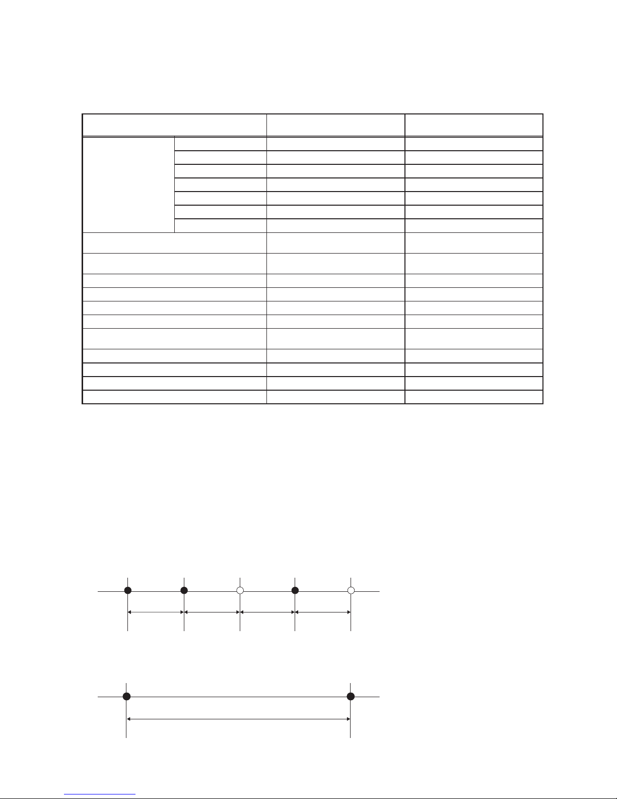
(3) Request interval
When sending “ReadProperty” or “WriteProperty” from the building management system to the
AE-200/AE-50/EW-50, set the interval to 200 (ms/property) or above.
When sending 10 properties using “ReadPropertyMultiple”, wait for at least 2000 ms (= 200 ms × 10
properties) before sending another request to the AE-200/AE-50/EW-50.
ReadPropertyReadProperty WriteProperty
200 ms
ReadProperty WriteProperty
200 ms 200 ms200 ms
ReadProperty
ReadPropertyMultiple (10 properties)
2000 ms (200 ms × 10 properties)
Page 7
7
WT07919X04
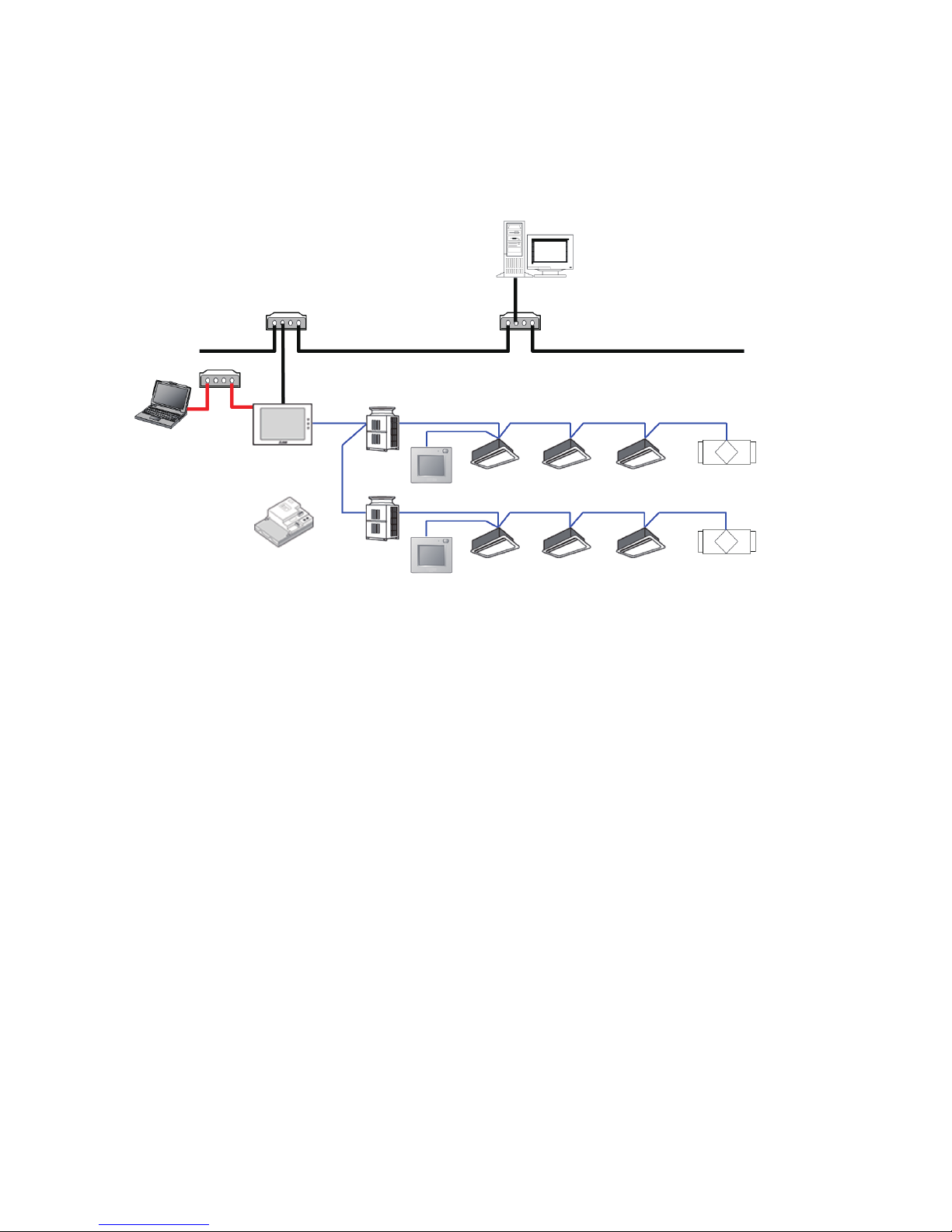
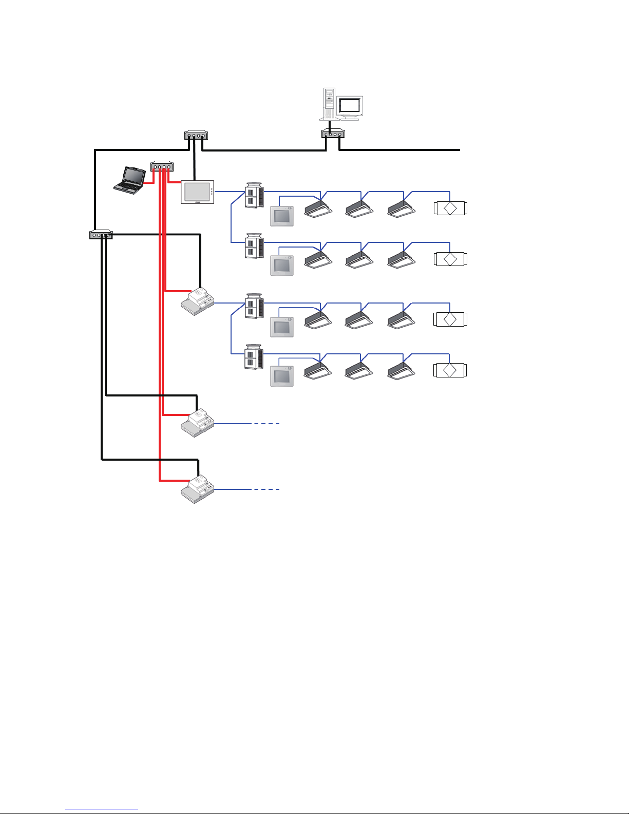
3. Usage (System configurations)
3-1. Sample system configurations
(1) When controlling 50 or fewer units of equipment and not using an apportioned electricity
billing function
*1 Use a switching HUB to connect to LAN1 and LAN2 (BACnet®). Do not connect LAN1 and LAN2 (BACnet®) to the same HUB.
*2 A PC (hereafter referred to as Setting PC) is required to make settings for the AE-200/EW-50 BACnet
®
functions. After making settings,
disconnect the Setting PC as well as LAN cables and HUBs used to connect to the Setting PC from the AE-200/EW-50. Refer to section
7 “Checking installation operations and performing trial run” for details.
Setting PC
*2
Outdoor unit
HUB
*1
Outdoor unit
ME remote controller
ME remote controller
Indoor unit
LAN1
Indoor unit
M-NET
LOSSNAY
M-NET
LOSSNAY
BACnet
®
HUB
*1
EW-50
M-NET
HUB
*1
AE-200
or
Building management system
LAN2
Page 8
8
WT07919X04
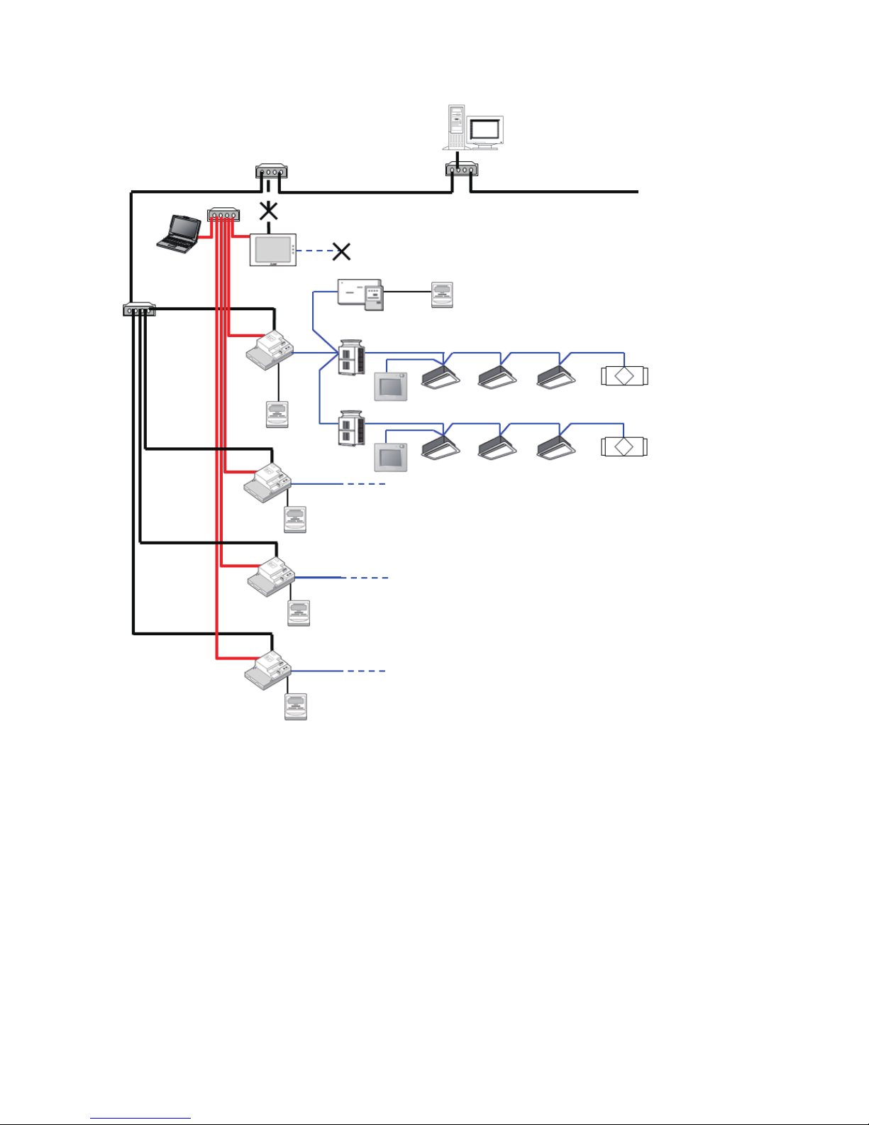
(2) When controlling more than 50 units of equipment *3 and not using an apportioned
electricity billing function
*1 Use a switching HUB to connect to LAN1 and LAN2 (BACnet®). Do not connect LAN1 and LAN2 (BACnet®) to the same HUB.
*2 A PC (hereafter referred to as Setting PC) is required to make settings for the AE-200/AE-50/EW-50 BACnet
®
functions. After making
settings, disconnect the Setting PC from the AE-200/AE-50/EW-50. Refer to section 7 “Checking installation operations and performing
trial run” for details.
*3 Up to 50 units of equipment can be connected to and controlled by each AE-200/AE-50/EW-50. If performing centralized control with an
AE-200, up to 3 AE-50/EW-50 can be connected to a single AE-200 (if not using AE-200 M-NET, up to 4 can be connected).
*4 If performing centralized control with an AE-200, because time synchronization from the building management system comes through
the AE-200, then for systems including those that do not have BACnet
®
control functions, configure so that AE-200 is connected to the
BACnet®, by connecting devices to control with BACnet® to the AE-200.
Setting PC
*2
HUB
*1
LAN1
M-NET
BACnet
®
HUB
*1
AE-50/EW-50
HUB
*1
Building management system
HUB
*1
AE-200
*4
/EW-50
Outdoor
unit
LAN2
LAN1
ME remote controller
Outdoor
unit
M-NET
ME remote controller
M-NET
Outdoor
unit
M-NET
Indoor unit
ME remote controller
Outdoor
unit
Indoor unit
M-NET
LAN2
LAN1
ME remote controller
M-NET
M-NET
Indoor unit
AE-50/EW-50
LOSSNAY
Outdoor unit/indoor unit etc.
LAN2
Indoor unit
LAN1
LOSSNAY
M-NET
AE-50/EW-50
LOSSNAY
Outdoor unit/indoor unit etc.
LOSSNAY
LAN2
Page 9
9
WT07919X04
(3) When using an apportioned electricity billing function
*4
*1 Use a switching HUB to connect to LAN1 and LAN2 (BACnet®). Do not connect LAN1 and LAN2 (BACnet®) to the same HUB.
*2 A PC (hereafter referred to as Setting PC) is required to make settings for the AE-50/EW-50 BACnet
®
functions. After making settings,
disconnect the Setting PC from the AE-50/EW-50. Refer to section 7 “Checking installation operations and performing trial run” for
details.
*3 If using the apportioned electricity billing function, we recommend that instead of using the AE-50/EW-50 built-in Pulse Input (PI), the PI
controller be used for measurement of electric energy.
(If AE-50/EW-50 built-in Pulse Input (PI) is used, pulse input will not be possible when the AE-50/EW-50 is stopped, during power
outages or during software updates. This could result in discrepancies between the measurements and the actual electric energy
consumed.)
When using the AE-50/EW-50 built-in Pulse Input (PI), approve the above-mentioned restrictions for the customer and then use.
*4 Up to 50 units of equipment can be connected to and controlled by each AE-50/EW-50. Up to 4 AE-50/EW-50 controllers can be
connected to each AE-200 for billing function.
*5 To use an apportioned electricity billing function and perform date and time synchronization from the building management system, set
the “Time Master/Sub” setting to “Sub” on the AE-200 for billing function and synchronize the time from AE-50/EW-50 connected to
BACnet
®
. The “Time Master/Sub” setting can be made on the Initial Setting Tool, Web Browser for Initial Settings, or AE-200/AE-50’s
LCD. (Refer to the AE-200/AE-50/EW-50 Instruction Book (Initial Settings) for settings methods.)
*6 If using the apportioned electricity billing function, connection of M-NET and Pulse Input (PI) to the AE-200 for billing function is
prohibited. Accordingly, the AE-200 for billing functions does not have any BACnet
®
control devices, and BACnet® connection is not
necessary. As a result, BACnet® settings and "BACnet connection" license are not required for the AE-200 for billing function.
*7 If using the apportioned electricity billing function, connection of LAN1 for transfer of power apportioning information is required.
Setting PC
*2
HUB
*1
LAN1
*7
M-NET
BACnet
®
HUB
*1
AE-50/
EW-50
HUB
*1
Building management system
HUB
*1
AE-200
*5 *6
LAN2
LAN1
*7
PI controller
Outdoor
unit
M-NET
ME remote controller
Outdoor
unit
M-NET
ME remote controller
Indoor unit
M-NET
LAN2
LAN1
*7
M-NET
Indoor unit
AE-50/EW-50
Outdoor unit/indoor unit etc.
LAN2
LAN1
*7
LOSSNAY
M-NET
AE-50/EW-50
LOSSNAY
Outdoor unit/indoor unit etc.
LAN2
LAN1 needs to be connected to the AE-200 for billing function.
LAN2 (BACnet
®
), M-NET, and Pulse Input (PI) cannot be connected to the AE-200 for
billing function.
Electricity meter
*3
Electricity meter
LAN1
*7
LAN2
AE-50/
EW-50
M-NET
Pulse signal
Electricity meter
*3
Outdoor unit/indoor unit etc.
Pulse signal
Electricity meter
*3
Pulse signal
Electricity meter
*3
Pulse
signal
Pulse
signal
Page 10
10
WT07919X04
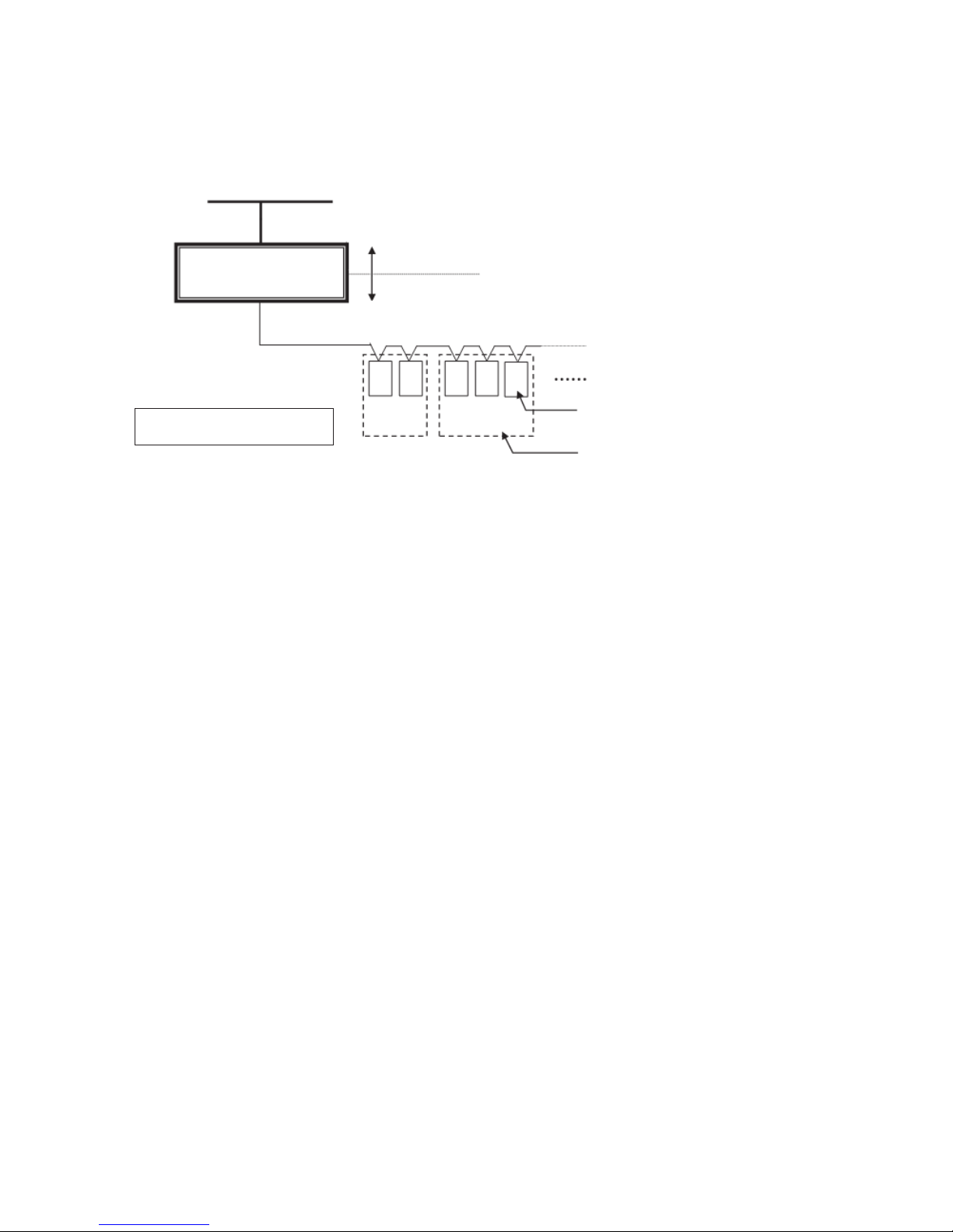
3-2. Group configurations
The basic functions of the BACnet® function can be performed for each unit group.
Multiple indoor units (ICs) in a group can collectively be controlled.
The group number is a range of 1 to 50.
Building management system
BACnet
®
AE-200/AE-50/EW-50
LAN2
M-NET
* Outdoor units and remote
controllers are omitted in this figure.
Air conditioning equipment
IC
01
Group
No. 1
IC
02
IC
03
IC (Indoor unit)
IC
04
Group
No. 2
IC
05
Unit address
Group number
Page 11

11
WT07919X04
4. Usage (Communication specifications)
4-1. BACnet® specifications
BACnet® communication specifications are based on ANSI/ASHRAE Standard 135-2010.
4-2. Communication protocol specifications
(1) Overview of protocol
• Use BACnet®/IP based on ANSI/ASHRAE Standard 135-2010 on UDP/IP of Ethernet®*.
• LAN2 is used to connect BACnet
®
.
Ether header IP header UDP header BVLL header NPCI header APDU
* Ethernet
®
is a registered trademark of Fuji Xerox Co., Ltd.
(2) Ether header
The physical layer is Ethernet® and the specifications are 100BASE-TX.
(3) IP header
A Class C private address is recommended *1. The sub-net mask is 255. 255. 255. 0.
*1 Recommended values (range): [192.168.2.1] to [192.168.254.254]
[192.168.0.0] and [192.168.255.255] should not be used for a LAN2 IP address.
An IP address set using LAN1 should not be used as a LAN2 IP address.
LAN1 and LAN2 network addresses must not be the same.
(4) UDP header
47808 (0xBAC0) is recommended for the default UDP port for unicast and broadcast.
(5) BVLL header
BVLC type (1 octet): 0x81 fixed (BVLL for BACnet®/IP)
BVLC function (1 octet): 0x0A for unicast
0x0B for broadcast
BVLC length (2 octets): Variable (BVLL header (4) + APDU data length)
(The above is a typical example. For details, refer to ANSI/ASHRAE Standard 135-2010.)
(6) BACnet® NETWORK NPCI header
Version (1 octet): 0x01 fixed
Control (1 octet): 0x04 with response message
0x00 without response message
(The above is a typical example. For details, refer to ANSI/ASHRAE Standard 135-2010.)
(7) APDU for BACnet
®
Data of 1,024 octets and under.
(Refer to ANSI/ASHRAE Standard 135-2010 for details.)
Page 12

12
WT07919X04
4-3. Objects
Support status for objects and for BACnet® functions are listed below.
V: Supported
—: Not supported
Object type
*1
Abbreviation
Supported/
Not supported
Object
Access Credential (32) — —
Access Door (30) — —
Access Point (33) — —
Access Rights (34) — —
Access User (35) — —
Access Zone (36) — —
Accumulator (23) AC V
Group Apportioned Electric Energy
Interlocked Units Apportioned Electric Energy
PIcontroller Electric Energy 1–4
Pulse Input Electric Energy 1–4
Group Apportionment Parameter
Interlocked Units Apportionment Parameter
Analog Input (0) AI V
Room Temp [Water Temp]
Error Code Detail
Analog Output (1) — —
Analog Value (2) AV V
Set Temp [Set Water Temp]
Set Temp Cool
Set Temp Heat
Set Temp Auto
Set High Limit Setback Temp
Set Low Limit Setback Temp
Averaging (18) — —
Binary Input (3) BI V
On Off State
Alarm Signal
*2
Filter Sign [Circulating Water Exchange Sign]
M-NET Communication State
Night Purge State
Thermo On Off State
System Alarm Signal
*2
External Heat Source State
PIcontroller Alarm Signal
*2
Binary Output (4) BO V On Off Setup
*3
Binary Value (5) BV V
Filter Sign Reset [Circulating Water Exchange Sign Reset]
Prohibition On Off
*3
Prohibition Mode
Prohibition Filter Sign Reset [Prohibition Circulating Water
Exchange Sign Reset]
Prohibition Set Temperature
Prohibition Fan Speed
System Forced Off (individual)/(collective)
*4
BitString Value (39) — —
Calendar (6) — —
CharacterString
Value
(40) — —
Command (7) — —
Credential Data Input (37) — —
Date Pattern Value (41) — —
Date Value (42) — —
DateTime Pattern
Value
(43) — —
DateTime Value (44) — —
Device (8) DEV V Device object of AE-200/AE-50/EW-50
Event Enrollment (9) — —
Event Log (25) — —
Page 13

13
WT07919X04
Object type
*1
Abbreviation
Supported/
Not supported
Object
File (10) — —
Global Group (26) — —
Group (11) — —
Integer Value (45) — —
Large Analog Value (46) — —
Life Safety Point (21) — —
Life Safety Zone (22) — —
Load Control (28) — —
Loop (12) — —
Multi-state Input (13) MI V
Error Code
Operational Mode State
Fan Speed State
Air Direction State
Ventilation Mode State
Air To Water Mode State
Multi-state Output (14) MO V
Operational Mode Setup
Fan Speed Setup
Air Direction Setup
Ventilation Mode Setup
Air To Water Mode Setup
Multi-state Value (19) — —
Network Security (38) — —
Notification Class (15) CLS V Notification Class
OctetString Value (47) — —
Positive Integer
Value
(48) — —
Program (16) — —
Pulse Converter (24) — —
Schedule (17) — —
Structured View (29) — —
Time Pattern Value (49) — —
Time Value (50) — —
Trend Log (20) LOG V
Trend Log Room Temp
Trend Log Group Apportioned Electric Energy
Trend Log Interlocked Units Apportioned Electric Energy
Trend Log PIcontroller Electric Energy 1–4
Trend Log Pulse Input Electric Energy 1–4
Trend Log Group Apportionment parameter
Trend Log Interlocked Units Apportionment parameter
Trend Log Multiple (27) — —
*1 Values within parentheses are “Object_Type” property values.
*2 Outputs an error code (4-digit) in Description and Message Text of event notification.
*3 Do not use this when “External Input Setting” for AE-200/AE-50/EW-50 is set to “ON/OFF (Level signal)”. “External Input Setting” can
be configured on the Initial Setting Tool, Web Browser for Initial Settings, or AE-200/AE-50’s LCD. (Refer to the AE-200/AE-50/EW-50
Instruction Book (Initial Settings) for settings methods.)
*4 Executes the stop command and remote controller operation prohibition (run/stop) command for air conditioning units.
Page 14

14
WT07919X04
4-4. Services
The BACnet® service support status is shown below.
V: Supported
—: Not supported
Initiate request: Provides services
Execute request: Receives and uses services
Service Initiate request Execute request
1. Alarm and Event Services
(1) Acknowledge Alarm Service — —
(2) ConfirmedCOVNotification Service V —
(3) ConfirmedEventNotification Service V —
(4) GetAlarmSummary Service — —
(5) GetEnrollmentSummary service — —
(6) GetEventInformation Service — V
(7) LifeSafetyOperation Service — —
(8) SubscribeCOV Service
*1
— V
(9) SubscribeCOVProperty Service — —
2. File Access Services
(1) AtomicReadFile Service — —
(2) AtomicWriteFile Service — —
3. Object Access Services
(1) AddListElement Service — V
(2) RemoveListElement Service — V
(3) CreateObject Service — —
(4) DeleteObject Service — —
(5) ReadProperty Service — V
(6) ReadPropertyConditional Service — —
(7) ReadPropertyMultiple Service — V
(8) ReadRange Service — V
(9) WriteProperty Service — V
(10) WritePropertyMultiple Service — V
4. Remote Device Management Services
(1) DeviceCommunicationControl Service — —
(2) ConfirmedPrivateTransfer Service — —
(3) ConfirmedTextMessage Service — —
(4) ReinitializeDevice Service — —
5. Virtual Terminal Services
(1) VT-Open Service — —
(2) VT-Close Service — —
(3) VT-Data Service — —
6. Security Services
(1) Authenticate Service — —
(2) Request Key Service — —
7. Unconfirmed Services
(1) I-Am V V
Page 15

15
WT07919X04
Service Initiate request Execute request
(2) I-Have V —
(3) UnconfirmedCOVNotification Service V —
(4) UnconfirmedEventNotification Service V —
(5) UnconfirmedPrivateTransfer Service — —
(6) UnconfirmedTextMessage Service — —
(7) TimeSynchronization Service — V
(8) UTCTimeSynchronization Service — —
(9) Who-Has — V
(10) Who-Is V V
*1 The maximum number of COV notifications which can be registered is 3,150. However, 5 is the maximum number of COV notifications
which can be registered in which Lifetime is not = 0.
Page 16

16
WT07919X04
4-5. Services for each object
The table below lists the supported services for each object.
○
: Supported
△
: Settings can be changed on the BACnet
®
Setting Tool.
INIT: Provides services (Initiate)
EXEC: Receives and executes services (Execute)
Device
Analog Input
Analog Value
Binary Input
Binary Output
Binary Value
Multi-State Input
Multi-State Output
Notification Class
Accumulator
Trend Log
ConfirmedCOVNotification
INIT
△ △ △ △ △ △ △
EXEC
ConfirmedEventNotification
INIT
△ △ △ △
EXEC
GetEventInformation
INIT
EXEC
○
SubscribeCOV
INIT
EXEC
○
AddListElement
INIT
EXEC
○
RemoveListElement
INIT
EXEC
○
ReadProperty
INIT
EXEC
○ ○ ○ ○ ○ ○ ○ ○ ○ ○ ○
ReadPropertyMultiple
INIT
EXEC
○ ○ ○ ○ ○ ○ ○ ○ ○ ○ ○
ReadRange
INIT
EXEC
○ ○ ○
WriteProperty
INIT
EXEC
○ ○ ○ ○ ○ ○ ○ ○ ○
WritePropertyMultiple
INIT
EXEC
○ ○ ○ ○ ○ ○ ○ ○ ○
I-Am
INIT
○
EXEC
○
I-Have
INIT
○
EXEC
UnconfirmedCOVNotification
INIT
△ △ △ △ △ △ △
EXEC
UnconfirmedEventNotification
INIT
△ △ △ △
EXEC
TimeSynchronization
INIT
EXEC
△
Who-Has
INIT
EXEC
○
Who-Is
INIT
○
EXEC
○
Object
Service
Page 17

17
WT07919X04
5. Usage (Function specifications)
The AE-200/AE-50/EW-50 BACnet® function mutually converts communications for air conditioning equipment
connected to the AE-200/AE-50/EW-50 and for BACnet® communications.
5-1. Controller functions and BACnet® functions
The table below lists the supported controller functions which can monitor/operate from the web browser or the
AE-200/AE-50’s LCD and the BACnet® functions.
V: Supported
—: Not supported
Classification Item Controller function BACnet® function Remarks
Monitor/
Operation
On Off Setup V V
On Off State V V
Operational Mode Setup V V
Operational Mode State V V
Fan Speed Setup V V
Fan Speed State V V
Air Direction Setup V V
BACnet
®
does not support
“Downblow 20%” and “Auto”
settings.
Air Direction State V V
BACnet
®
does not support
“Downblow 20%” and “Auto”
settings.
Room Temp
[Water Temp]
V V
Set Temp
[Set Water Temp]
V V
Set Temp Cool V V
Set Temp Heat V V
Set Temp Auto V V
Set High Limit Setback Temp V V
Only
AE-200A/AE-50A/EW-50A
Set Low Limit Setback Temp V V
Only
AE-200A/AE-50A/EW-50A
Ventilation Mode Setup V V
Ventilation Mode State V V
Air To Water Mode Setup V V
Air To Water Mode State V V
Night Purge Setup V —
Night Purge State V V
Prohibition On Off V V
Prohibition Mode V V
Prohibition Filter Sign Reset
[Prohibition Circulating Water
Exchange Sign Reset]
V V
Prohibition Set Temperature V V
Prohibition Timer V —
Prohibition Air Direction V —
Prohibition Fan Speed V V
System Forced Off
(individual)
V V
System Forced Off
(collective)
V V
Thermo On Off State V
*1
V
*2
External Heat Source State — V
Output status of indoor unit
CN24
Page 18

18
WT07919X04
Classification Item Controller function BACnet® function Remarks
Alarm monitor
Alarm Signal (Air conditioning
unit/PI controller)
V V
Error Code V V
Controllers support 4-digit error
codes, and BACnet
®
supports
1- and 4-digit error codes.
System Alarm Signal V V
M-NET Communication State V V
Filter Sign
[Circulating Water Exchange
Sign]
V V
Filter Sign Reset
[Circulating Water Exchange
Sign Reset]
V V
Control
functions
Command Failure — V
High Limit/Low Limit Alarm V
*3
V
Night Setback control V —
Schedule control V —
Interlock control V —
Data
management
functions
Energy management data/
Trend log
V V
These are collected individually
in the body/BACnet
®
, so
sometimes the values of these
do not coincide.
Group Apportioned Electric
Energy
V V
Interlocked Units Apportioned
Electric Energy
V V
Group Apportionment
Parameter
V V
BACnet
®
function has only
parameters for outdoor units.
Interlocked Units
Apportionment Parameter
V V
BACnet
®
function has only
parameters for outdoor units.
PIcontroller Electric Energy
(Ch 1–4)
V V
Pulse Input Electric Energy
(Metering device 1–4)
V V
Other
functions
Unit of temperature setting V V
This setting on the
AE-200/AE-50/EW-50 and
the one on the BACnet
®
are
different. On the BACnet
®
,
only the unit of temperature
that is used for BACnet
®
communication can be set.
Cumulative operation time/
FAN operation time
V —
Time management V V
BACnet
®
router — V
LCD lock V —
*1 Supports only Thermo-ON time, Thermo-ON/OFF count.
Thermo-ON/OFF count cannot be monitored from the AE-200/AE-50’s LCD or web browser, but can be checked with the CSV output
function.
*2 Supports only Thermo-ON/OFF state.
*3 Alarms can occur when the upper and lower limit values are exceeded due to the AI controller (option).
Page 19

19
WT07919X04
5-2. Basic functions
Sends commands from the building management system to air conditioning equipment. Additionally, sends the
air conditioning equipment status to the building management system.
5-2-1. Instance number for basic functions
The instance number is configured of the object type + fixed value “1” + group number + member number.
Instance number (6 digits in decimal notation): 0 1 xx xx
Objects that can be used with the AE-200/AE-50/EW-50 are shown in the table below.
Object
Object
type
Instance
number
Units
RemarksInactive(0)
*23
Active(1)
Text-1(1)
*23
Text-2(2) Text-3(3) Text-4(4) Text-5(5)
On Off Setup BO 01xx01 Stop Run
*20
On Off State BI 01xx02 Stop Run
*20
Alarm Signal BI 01xx03 Normal Error
Error Code MI 01xx04
01: Normal
02: Other errors
03: Refrigeration system
fault
04: Water system error
05: Air system error
06: Electronic system error
07: Sensor fault
08: Communication error
09: System error
Operational Mode
Setup
MO 01xx05
01: Cool
02: Heat
03: Fan
04: Auto
05: Dry
06: Setback
*1 *16 *18
*22
Operational Mode
State
MI 01xx06
01: Cool
02: Heat
03: Fan
04: Auto
05: Dry
06: Setback
*1 *3 *16
*18 *22
Fan Speed Setup MO 01xx07
01: Low
02: High
03: Mid 2
04: Mid 1
05: Auto
*4 *5 *18
Fan Speed State MI 01xx08
01: Low
02: High
03: Mid 2
04: Mid 1
05 Auto
*4 *5 *18
*21
Room Temp
[Water Temp]
AI 01xx09 ºF/ºC
*16
Set Temp
[Set Water Temp]
AV 01xx10 ºF/ºC
*16
Filter Sign
[Circulating Water
Exchange Sign]
BI 01xx11 OFF ON
Filter Sign Reset
[Circulating Water
Exchange Sign
Reset]
BV 01xx12 Reset Void
Prohibition On Off BV 01xx13 Permit Prohibit
*20
Prohibition Mode BV 01xx14 Permit Prohibit
*16
Prohibition Filter Sign
Reset
[Prohibition
Circulating Water
Exchange Sign
Reset]
BV 01xx15 Permit Prohibit
Member number (01–99)
Group number (01–50), Collective (99), Others
“1” fixed
Object class
(by group: (0), by PI controller (4), by interlocked unit (6))
Page 20

20
WT07919X04
Object
Object
type
Instance
number
Units
RemarksInactive(0)
*23
Active(1)
Text-1(1)
*23
Text-2(2) Text-3(3) Text-4(4) Text-5(5)
Prohibition Set
Temperature
BV 01xx16 Permit Prohibit
*16
Prohibition Fan
Speed
BV 01xx17 Permit Prohibit
M-NET
Communication
State
BI 01xx20 Normal Error
System
Forced
Off
individual
BV
01xx21
Reset Execute
*10 *11
collective 019921
Air Direction Setup MO 01xx22 Horizontal
Downblow
60%
Downblow
80%
Downblow
100%
Swing
*14 *16
*18
Air Direction State MI 01xx23 Horizontal
Downblow
60%
Downblow
80%
Downblow
100%
Swing
*8 *14 *16
*18
Set Temp Cool AV 01xx24 ºF/ºC
*16 *18
Set Temp Heat AV 01xx25 ºF/ºC
*16 *18
Set Temp Auto AV 01xx26 ºF/ºC
*16 *18
Set High Limit
Setback Temp
AV 01xx27 ºF/ºC
*16 *18
*19
Set Low Limit
Setback Temp
AV 01xx28 ºF/ºC
*16 *18
*19
Ventilation Mode
Setup
MO 01xx35
Heat
Recovery
Bypass Auto
*15 *18
Ventilation Mode
State
MI 01xx36
Heat
Recovery
Bypass Auto
*15 *18
*21
Air To Water Mode
Setup
MO 01xx37 Heating
Heating
ECO
Hot Water
Anti-
freeze
Cooling
*15 *16
*17
Air To Water Mode
State
MI 01xx38 Heating
Heating
ECO
Hot Water
Anti-
freeze
Cooling
*15 *16
*17
Group Apportioned
Electric Energy
AC 01xx39 0.1 [kWh]
*2
Interlocked Units
Apportioned Electric
Energy
AC 61aa39 0.1 [kWh]
*2 *7
PIcontroller Electric
Energy 1–4
AC 41mm40–43 0.1 [kWh]
*2 *6 *13
*15 *16
*17 *18
Pulse Input Electric
Energy 1–4
AC 410040–43 0.1 [kWh]
*2 *12 *13
*15 *16
*17 *18
Group Apportionment
Parameter
AC 01xx44 No Units
*2
Interlocked Units
Apportionment
Parameter
AC 61aa44 No Units
*2 *7
Night Purge State BI 01xx46 OFF ON
*15 *18
Thermo On Off State BI 01xx47 OFF ON
*16
System Alarm Signal BI 010048 Normal Error
Error Code Detail AI 01xx49 No Units
External Heat Source
State
BI 01xx50 OFF ON
PIcontroller Alarm
Signal
BI 41mm03 Normal Error
*6
Trend Log Room
Temp
LOG 01xx80
*9 *16 *24
Page 21

21
WT07919X04
Object
Object
type
Instance
number
Units
RemarksInactive(0)
*23
Active(1)
Text-1(1)
*23
Text-2(2) Text-3(3) Text-4(4) Text-5(5)
Trend Log Group
Apportioned Electric
Energy
LOG 01xx83
*2 *24
Trend Log
Interlocked Units
Apportioned Electric
Energy
LOG 61aa83
*2 *7 *24
Trend Log
PIcontroller Electric
Energy 1–4
LOG 41mm84–87
*2 *6 *13
*15 *16 *17
*18 *24
Trend Log Pulse
Input Electric Energy
1–4
LOG 410084–87
*2 *13 *15
*16 *17
*18 *24
Trend Log Group
Apportionment
Parameter
LOG 01xx88
*2 *24
Trend Log
Interlocked Units
Apportionment
Parameter
LOG 61aa88
*2 *7 *24
*1 “Dry” can be used only when the “Use Dry Mode” setting is enabled (checked) on the BACnet® Setting Tool. (The default setting is
disabled (unchecked).)
*2 “Charge” license is required for AE-200/AE-50/EW-50.
*3 When the “Operational Mode State” received from the indoor unit is “Auto Cool”, “Cool” can be selected; when it is “Auto Heat”, “Heat”
can be selected, or “Auto” can be selected for both.
*4 “Use Fan Speed Mid1/Mid2” setting of the BACnet
®
Setting Tool, and effective fan speeds from indoor unit, LOSSNAY, and OA
Processing Unit fan speed switching steps are shown in the table below. (The default setting of “Use Fan Speed Mid1/Mid2” of the
BACnet® Setting Tool is disabled (unchecked).)
(In the automatic wind velocity compatible model, “Auto” is valid in addition to the fan speed in this table.)
V: Available
Unit type “Use Fan Speed Mid1/Mid2” setting
Number of available
fan speeds
Available fan speed
Low Mid 2 Mid 1 High
Indoor unit
Enabled
2 V V
3 V V V
4 V V V V
Disabled 2–4
V
V
LOSSNAY and OA
Processing Unit
Enabled
1 V
2
V
V
3
V V
V
4
V V V
V
Disabled
1 V
2–4 V V
*5 Low < Mid 2 < Mid 1 < High
*6 mm: PI controller address (01–50)
*7 Can be used only for the interlocked units.
aa: Interlocked unit address (01–50)
*8 When the air direction received from the indoor unit is “Downblow 20%” or “Auto”, “Horizontal” will be output to BACnet
®
.
*9 The value of the “Present_Value” in the “Room Temp” (AI_01xx09) object is logged in as the log record.
*10 Batch commands are made for the “System Forced Off” instance number (019921) for all groups.
*11 When the “System Forced Off” (individual/collective) from BACnet
®
communication is used, do not set the “External Input Setting” for
AE-200/AE-50/EW-50 to “ON/OFF (Level signal)”. “External Input Setting” can be configured on the Initial Setting Tool, Web Browser for
Initial Settings, or AE-200/AE-50’s LCD. (Refer to the AE-200/AE-50/EW-50 Instruction Book (Initial Settings) for settings methods.)
*12 Electric energy for the electricity meter connected to the Pulse Input (PI) of AE-50/EW-50
*13 Electric energy 1 to 4 correspond to signal lines Ch1 to 4 on the PI controller or metering devices 1 to 4 connected to Pulse Input (PI) of
AE-50/EW-50.
Page 22

22
WT07919X04
*14 It may differ from the actual air direction depending on the type of indoor unit (Ceiling-concealed Ducted, Wall-mounted, Floor-standing).
An example of a Floor standing PFFY-P VKM-E is as follows.
Setting/Status
Air direction on the
BACnet
®
Horizontal Downblow 60% Downblow 80% Downblow 100% Swing
Actual air direction Upblow 100% Upblow 80% Upblow 60% Horizontal Swing
*15 Cannot be used with an indoor unit model.
Differences in supported/not supported objects depending on whether it is an indoor unit, LOSSNAY or the Air To Water model are
indicated on the following page.
*16 Cannot be used with a LOSSNAY which is not interlocked with an indoor unit.
Differences in supported/not supported objects depending on whether it is an indoor unit, LOSSNAY or the Air To Water model are
indicated on the following page.
*17 Cannot be used with an OA Processing Unit which is not interlocked with an indoor unit.
Differences in supported/not supported objects depending on whether it is an indoor unit, LOSSNAY or the Air To Water model are
indicated on the following page.
*18 Cannot be used with an Air To Water model.
Differences in supported/not supported objects depending on whether it is an indoor unit, LOSSNAY or the Air To Water model are
indicated on the following page.
*19 It can only be used if the system controller is AE-200A/AE-50A/EW-50A and the indoor unit is a Setback mode supported model.
*20 Do not use this when “External Input Setting” for AE-200/AE-50/EW-50 is set to “ON/OFF (Level signal)”. “External Input Setting” can
be configured on the Initial Setting Tool, Web Browser for Initial Settings, or AE-200/AE-50’s LCD. (Refer to the AE-200/AE-50/EW-50
Instruction Book (Initial Settings) for settings methods.)
*21 During Night Purge state, this operates using a specific fan speed and ventilation mode, but these are not reflected in the status display.
As a result, the read status from BACnet
®
communications may differ from actual fan speeds and ventilation modes. Additionally,
carrying out fan speed and ventilation mode settings during Night Purge state will not change actual operation, and these will only be
reflected in the status display.
*22 “Setback” is available only when the “Old model compatibility mode” is set to “OFF” on the Initial Setting Tool, Web Browser for Initial
Settings, or AE-200/AE-50’s LCD.
*23 “Inactive(0),Active(1)” is applied when the object type is BO/BI/BV, and “Text-1(1),Text-2(2),···” is applied when the object type is MO/MI.
*24 Use the BACnet
®
Trial Run Tool to check or set the “Log_Interval” property. (Refer to the AE-200/AE-50/EW-50 Instruction Book (BACnet®
Trial Run Tool) for settings methods.)
Page 23

23
WT07919X04
Whether or not the object can be supported by the unit type is indicated in the following table.
The AE-200/AE-50/EW-50 only creates objects supported by each group.
V: Supported
—: Not supported
Object
Object
type
Instance
number
Unit type
Remarks
Indoor unit
and
OA Processing
Unit that is not
interlocked with
indoor units
LOSSNAY unit that
is not interlocked
with indoor units
Air To Water
On Off Setup BO 01xx01 V V V
*5
On Off State BI 01xx02 V V V
Alarm Signal BI 01xx03 V V V
Error Code MI 01xx04 V V V
Operational Mode Setup MO 01xx05 V — —
Operational Mode State MI 01xx06 V — —
Fan Speed Setup MO 01xx07 V V —
Fan Speed State MI 01xx08 V V —
Room Temp
[Water Temp]
AI 01xx09 V — V
Set Temp
[Set Water Temp]
AV 01xx10 V — V
*2
Filter Sign
[Circulating Water Exchange
Sign]
BI 01xx11 V V V
Filter Sign Reset
[Circulating Water Exchange
Sign Reset]
BV 01xx12 V V V
Prohibition On Off BV 01xx13 V V V
*5
Prohibition Mode BV 01xx14 V — V
Prohibition Filter Sign Reset
[Prohibition Circulating Water
Exchange Sign Reset]
BV 01xx15 V V V
Prohibition Set Temperature BV 01xx16 V — V
Prohibition Fan Speed BV 01xx17 V — —
*1 *6
M-NET Communication State BI 01xx20 V V V
System
Forced Off
individual
BV
01xx21
V V V
collective 019921
Air Direction Setup MO 01xx22 V — —
*1
Air Direction State MI 01xx23 V — —
*1
Set Temp Cool AV 01xx24 V — —
*2
Set Temp Heat AV 01xx25 V — —
*2
Set Temp Auto AV 01xx26 V — —
*2
Set High Limit Setback Temp AV 01xx27 V — —
Set Low Limit Setback Temp AV 01xx28 V — —
Ventilation Mode Setup MO 01xx35 V V —
*3
Ventilation Mode State MI 01xx36 V V —
*3
Air To Water Mode Setup MO 01xx37 — — V
Air To Water Mode State MI 01xx38 — — V
Group Apportioned Electric
Energy
AC 01xx39 V V V
Interlocked Units Apportioned
Electric Energy
AC 61aa39 — — —
*4
Page 24

24
WT07919X04
Object
Object
type
Instance
number
Unit type
Remarks
Indoor unit
and
OA Processing
Unit that is not
interlocked with
indoor units
LOSSNAY unit that
is not interlocked
with indoor units
Air To Water
PIcontroller Electric Energy
1–4
AC 41mm40–43 — — —
Pulse Input Electric Energy
1–4
AC 410040–43 — — —
Group Apportionment
Parameter
AC 01xx44 V — V
Interlocked Units
Apportionment Parameter
AC 61aa44 — — —
*4
Night Purge State BI 01xx46 V V —
*3
Thermo On Off State BI 01xx47 V — V
Error Code Detail AI 01xx49 V V V
External Heat Source State BI 01xx50 V — —
*7
PIcontroller Alarm Signal BI 41mm03 — — —
Trend Log Room Temp LOG 01xx80 V — V
Trend Log Group Apportioned
Electric Energy
LOG 01xx83 V V V
Trend Log Interlocked Units
Apportioned Electric Energy
LOG 61aa83 — — —
*4
Trend Log PIcontroller
Electric Energy 1–4
LOG 41mm84–87 — — —
Trend Log Pulse Input Electric
Energy 1–4
LOG 410084–87 — — —
Trend Log Group
Apportionment Parameter
LOG 01xx88 V — V
Trend Log Interlocked Units
Apportionment Parameter
LOG 61aa88 — — —
*4
*1 An OA Processing Unit which is not interlocked with an indoor unit is not supported.
*2 An example of the temperature setting range for the indoor unit/Air To Water is shown in the following table. (Indicates the setting
temperature range of a typical model. May differ depending on the model).
Indoor unit
Operational mode Cool Heat Auto Dry
Standard
model
Auto (Single-set-point)
mode
19–30ºC 17–28ºC 19–28ºC 19–30ºC
Auto (Dual-set-points)
mode
19–35ºC 4.5–28ºC
Cool: 19–35ºC
Heat: 4.5–28ºC
19–35ºC
Air To Water
Operational mode Heating Heating ECO Hot Water Anti-freeze Cooling
Booster unit (BU) 30–50ºC 30–45ºC 30–70ºC 10–45ºC Invalid
HEX unit (AU) 30–45ºC 30–45ºC Invalid 10–45ºC 10–30ºC
(Conversion for communication of the air conditioning equipment and BACnet
®
is carried out within a range of 0 to 99°C.)
*3 Supported only by LOSSNAY and OA Processing Unit that are not interlocked with indoor units.
*4 Supported by OA Processing Unit that is interlocked with indoor units.
*5 Do not use this when “External Input Setting” for AE-200/AE-50/EW-50 is set to “ON/OFF (Level signal)”. “External Input Setting” can
be configured on the Initial Setting Tool, Web Browser for Initial Settings, or AE-200/AE-50’s LCD. (Refer to the AE-200/AE-50/EW-50
Instruction Book (Initial Settings) for settings methods.)
*6 Can be used when the indoor unit supports “Prohibition Fan Speed”.
*7 Can be used on the unit models produced in April 2012 or later.
Page 25

25
WT07919X04
5-3. Set temperature objects
Select the set temperature objects below according to the indoor unit group configuration in a given air
conditioning system.
V: Selectable
—: Not selectable
Object
Object
type
Instance
number
Models that support the Auto (Dual-set-points) mode
*3
Models that do not
support the Auto
(Dual-set-points)
mode
*3
Auto (Single-set-
point) mode
*1
Auto (Dual-set-
points) mode
*1
Old model
compatibility mode
*2
Set Temp AV 01xx10 — — V V
Set Temp Cool AV 01xx24 V V — —
Set Temp Heat AV 01xx25 V V — —
Set Temp Auto AV 01xx26 V — — —
Set High Limit
Setback Temp
AV 01xx27 V
*4
V
*4
— —
Set Low Limit
Setback Temp
AV 01xx28 V
*4
V
*4
— —
*1 Auto (Single-set-point) mode or Auto (Dual-set-points) mode can be set on the local remote controller for each indoor unit. Refer to the
indoor unit Instruction Book for details about these modes.
*2 Old model compatibility mode can be collectively set for the M-NET system on the Initial Setting Tool, Web Browser for Initial Settings, or
AE-200/AE-50’s LCD. (Refer to the AE-200/AE-50/EW-50 Instruction Book (Initial Settings) for settings methods.)
*3 Selectable/Not selectable of Auto (Dual-set-points) mode is determined automatically for each group. (Group is treated as Auto (Dual-
set-points) mode selectable only if all indoor units, all remote controllers, and all system controllers are Auto (Dual-set-points) mode
selectable.)
*4 It can only be used if the system controller is AE-200A/AE-50A/EW-50A and the indoor unit is a Setback mode supported model.
(1) When the building management system supports two temperature setting (for cooling and
heating individually)
Use temperature setting object for “Set Temp” (AV_01xx10) in a group which includes an Auto (Dual-set-points)
mode unsupported model.
When operating an Auto (Single-set-point) mode indoor unit in the operation mode “Auto”, use the
temperature setting object for “Set Temp Auto” (AV_01xx26).
When operating an Auto (Dual-set-points) mode indoor unit in the operation mode “Auto”, use the
temperature setting object for “Set Temp Cool” (AV_01xx24) and “Set Temp Heat” (AV_01xx25).
(2) When the building management system supports only one temperature setting (common for
cooling and heating)
Set the “Old model compatibility mode” setting to “ON” on the Initial Setting Tool, Web Browser for Initial
Settings, or AE-200/AE-50’s LCD. Use the temperature setting object for “Set Temp” (AV_01xx10).
5-4. “System Forced Off” forced-reset function
“System Forced Off (individual/collective)” can be forcibly reset from the BACnet® Setting Tool when it cannot be
reset from the building management system due to a problem such as a communication error.
5-4-1. “System Forced Off” forced-reset function specifications
When forced-reset of “System Forced Off” is performed, the unit status will be as follows.
Unit Status
AE-200/AE-50/EW-50 “System Forced Off (individual/collective)” will all be set to “Reset (Inactive)”.
Air conditioning unit
Return the prohibition of remote controller operation (ON/OFF) to the state before “System
Forced Off” occurs.
Page 26

26
WT07919X04
5-5. Apportioned electricity billing function
The AE-200/AE-50/EW-50 apportioned electricity billing function calculates the “electric energy for the
electricity meter” and the “apportioned electric energy for the electricity meter per group/interlocked unit” or the
“apportionment parameters for apportioning the electric energy per group/interlocked unit,” and stores this in the
accumulator. Additionally, the accumulator is stored in “Log_Buffer” of the trend log.
The cumulative value and trend log data can be read by BACnet® communication.
BACnet® communications cannot read billing information.
When using the apportioned electricity billing function, a “Charge” license is required for each
AE-200/AE-50/EW-50. Refer to the AE-200/AE-50/EW-50 Instruction Book (Apportioned Electricity Billing
Function) for details on the apportioned electricity billing function.
When using the apportioned electricity billing function, refer to (3) “When using an apportioned electricity billing
function” in section 3-1 “Sample system configurations” for system configuration.
5-5-1. Apportioned electricity billing function specifications
The apportioned electricity billing function in the BACnet® function is configured of an accumulator object which
stores the electric energy and other cumulative value/apportioned results cumulative value and the trend log
object which reads the accumulator for each fixed time and accumulates the value. When using the apportioned
electricity billing function, a “Charge” license is required.
Note
An interlocked unit is an OA Processing Unit (FU attribute) linked to an indoor unit, and covers those
affiliated OA Processing Units that can be registered in the energy management block settings of the Initial
Setting Tool.
This does not refer to an OA Processing Unit (IC attribute) that is not linked to an indoor unit that can have
group settings performed through the centralized controller.
Accumulator specifications
Data type Apportioning type Contents
*3
Electric energy
*1 *4
Apportionment
source
Cumulative electric energy from electricity meter read from PI controller
Cumulative electric energy from electricity meter read from built-in Pulse
Input (PI) of AE-50/EW-50
Apportioned results
Electric energy for each group (indoor unit + outdoor unit)
*5
Electric energy for each interlocked unit (indoor unit + outdoor unit)
*5
Apportionment
parameter
*2 *4 *6
Apportionment
parameter
Apportionment parameters for each group (for outdoor units)
*5
Apportionment parameters for each interlocked unit (for outdoor units)
*5
*1 Electricity meter must be connected to obtain the electric energy. Also, apportionment calculation is carried out using AE-200 for
dedicated electricity apportionment.
*2 The electricity meter need not be connected to obtain the apportionment parameters. Select when carrying out apportionment
calculations in a building management system.
*3 Cumulative data for 30 minute cycles. (Data for until XX:00 and XX:30 minutes is updated at XX:15 and XX:45 respectively)
*4 The value can be compensated by writing the value in the “Value_Set” of the accumulator object.
*5 Stores apportionment results by the apportionment method set in the billing function settings for the apportioned electricity billing function.
*6 The apportionment parameter is a value that is proportionate to the electric energy consumption calculated based on the operation status
and operation time of each air conditioning unit, and will be the reference value for separately-calculating the electric energy (or electricity
charge) using the ratio of this value and the total value of apportionment parameters for all units.
• PIcontroller Electric Energy
• Pulse Input Electric Energy
Operating state of air
conditioning unit
Electric energy in
electricity meter
Apportioned
calculation
Accumulator object
• Group Apportioned Electric
Energy
• Interlocked Units Apportioned
Electric Energy
• Group Apportionment parameter
• Interlocked Units Apportionment
parameter
Accumulation
• Trend Log PIcontroller Electric Energy
• Trend Log Pulse Input Electric Energy
• Trend Log Group Apportioned Electric Energy
• Trend Log Interlocked Units Apportioned Electric
Energy
• Trend Log Group Apportionment parameter
• Trend Log Interlocked Units Apportionment
parameter
Trend Log object
Page 27

27
WT07919X04
Trend log specifications (only for portions related to the apportioned electricity billing function)
Item Setting contents Setting method
Collection cycle
30 minutes to 1440 minutes (1 day)
Can be set in 30-minute increments.
(“Log_Interval” property)
Initial value: 30 minutes
Settings on the building
management system
Collection period
4 days
*1
to 192 days
*2
(retain the value for the most recent 192 items)
Collection timing
Carry out collection for each collection cycle using 1970/1/1
00:00:00 as a starting point.
Collection starts After participation sequence completed (Status = Operational)
Log deleted When “0” is written to the “Record_Count” property
*1 When the collection cycle is 30 minutes
*2 When the collection cycle is 1 day
5-5-2. Accumulator object
The instance number of the accumulator object which stores the cumulative value is as follows.
Object
Object
type
Instance
number
Apportioning
type
Metering
device
Contents
Group Apportioned
Electric Energy
AC 01xx39
Apportioned
results
Required
Stores the cumulative value of the electric
energy (indoor unit + outdoor unit) for each
group.
Interlocked Units
Apportioned Electric
Energy
AC 61aa39
Stores the cumulative value of the electric
energy (indoor unit + outdoor unit) for each
interlocked unit (OA Processing Unit).
PIcontroller Electric
Energy 1–4
AC 41mm40–43
Apportionment
source data
Cumulative value (for 4 channels) of
electric energy accumulated in PI controller
Pulse Input Electric
Energy 1–4
AC 410040–43
Cumulative value (for 4 channels) of
electric energy accumulated in a built-in
Pulse Input (PI) of AE-50/EW-50
Group Apportionment
Parameter
AC 01xx44
Apportionment
parameter
Not
required
Stores electric energy apportionment
parameters (for outdoor units) for each
group.
Interlocked Units
Apportionment
Parameter
AC 61aa44
Stores electric energy apportionment
parameters (for outdoor units) for each
interlocked unit (OA Processing Unit).
* xx: Group number (01–50)
* mm: PI controller address (01–50)
* aa: Interlocked unit address (01–50)
Page 28

28
WT07919X04
5-5-3. Trend log object
Instance number of the trend log object (only the portion related to the apportioned electricity billing function)
which stores the accumulator log is as follows.
Object
Object
type
Instance
number
Apportioning
type
Metering
device
Contents
Trend Log Group
Apportioned Electric
Energy
LOG 01xx83
Apportioned
results
Required
Accumulates “Present_Value” of
accumulator (Group Apportioned Electric
Energy) for each collection cycle.
Trend Log Interlocked
Units Apportioned
Electric Energy
LOG 61aa83
Accumulates “Present_Value” of
accumulator (Interlocked Units Apportioned
Electric Energy) for each collection cycle.
Trend Log PIcontroller
Electric Energy 1–4
LOG 41mm84–87
Apportionment
source data
Accumulates “Present_Value” of
accumulator (PIcontroller Electric Energy
1–4) for each collection cycle.
Trend Log Pulse Input
Electric Energy 1–4
LOG 410084–87
Accumulates “Present_Value” of
accumulator (Pulse Input Electric Energy
1–4) for each collection cycle.
Trend Log Group
Apportionment
parameter
LOG 01xx88
Apportionment
parameter
Not
required
Accumulates “Present_Value” of
accumulator (Group Apportionment
parameter) for each collection cycle.
Trend Log Interlocked
Units Apportionment
Parameter
LOG 61aa88
Accumulates “Present_Value” of
accumulator (Interlocked Units
Apportionment Parameter) for each
collection cycle.
* xx: Group number (01–50)
* mm: PI controller address (01–50)
* aa: Interlocked unit address (01–50)
Note
If the apportioned electricity billing function is enabled and the power to the AE-200/AE-50/EW-50 is turned
on between 10 and 15, or between 40 and 45 minutes every hour, then when accumulator objects and trend
log objects are first collected, the object “Reliability” property may be other than “0” (indicating no reliability).
5-5-4. System restrictions for apportioned electricity billing function
• “Charge” license is required for each AE-200/AE-50/EW-50.
• Combinations of AE-200 and AE-50/EW-50 units are required.
• M-NET of AE-200 for billing function cannot be used.
• Built-in Pulse Input (PI) of AE-200 for billing function cannot be used.
• Electric energy measurement using a PI controller is recommended.
(If AE-50/EW-50 with built-in Pulse Input (PI) is used, pulse input will not be possible when the
AE-50/EW-50 is stopped, during power outages or during software updates. This could result in
discrepancies between the measurements and the actual electric energy consumed.)
• Ensure that the same software versions are used on AE-200/AE-50/EW-50 units.
• The apportioned electricity billing function (AE-200 Apportion) and apportioned electricity billing function
(TG-2000A Apportion) cannot be used together.
• When the apportioned electricity billing function (AE-200 Apportion) is being used and you intend to use
the TG-2000A integration software, check that the TG-2000A version is 6.60 or later.
• An electricity meter is required for each AE-200 and for each AE-200 system comprising expansion
controller AE-50/EW-50. You cannot make settings (apportionment settings) that span multiple AE-200
systems.
Page 29

29
WT07919X04
5-5-5. Notes on using the apportioned electricity billing function
• This function is our original electric energy apportionment system that apportions electric energy using
input from electricity meters with a pulse generator function. Rather than directly measuring the electric
energy consumed by each air conditioner, pulses are input based on the air conditioner usage by
determining the air conditioner operating status from the content of its communication with the indoor and
outdoor units.
To all users (user license agreement)
The information provided here constitutes an agreement between Mitsubishi Electric and the
customer.
If this “apportioned electricity billing function for the AE-200 air conditioning control system” is used,
this agreement assumes that the customer is using the aforementioned system having agreed to the
terms listed below.
• Mitsubishi Electric and its sales companies accept no liability whatsoever for any incidental,
consequential or special damages incurred by the customer, even where the sales company has
received notification of the potential for damages of that kind.
Nor is any liability accepted for any allegations regarding the rights of a third party.
Important
Any individual agreement between the building owner and a tenant regarding the use of this product
should incorporate the parties’ agreement to or accord with the fact that “charges for the use of air
conditioning will be collected in the form of apportioned totals based on the operating status of air
conditioners (including temporary measures to deal with faults)”.
• This is a system for estimating the operating electric energy consumed for air conditioning. As
such it cannot be used as a proof of transaction.
Also, amounts metered using electricity meters are also counted using pulse conversion and
cannot be used as a proof of transaction.
• This is not a system (or its equivalent) in which the operating electric energy consumed by each air
conditioner is directly measured at the location where the electricity is supplied.
• Because this is an apportionment method that uses the operating status of air conditioner indoor units,
even where the operating time for indoor units is the same, the amount of operating electric energy
consumed may differ depending on the model configuration and operating status of the outdoor units.
(The apportioned electric energy may be different when compared with a situation where an electricity
meter is assigned to each air conditioner.)
• Air conditioners still receive current even when stopped, and electric energy is apportioned to idle air
conditioners as standby electric energy.
• While the amounts of electric energy, water and gas consumed are obtained through pulse
conversion, factors such as performance and accuracy are dependent on the metering devices and
Mitsubishi Electric is in no way responsible for such factors.
• If electric power to the AE-200/AE-50/EW-50 and PI controller is interrupted due to a power outage but the
air conditioner is still running, electric energy cannot be apportioned correctly.
• Because the unit price digits for each tenant (energy management block) are rounded off in the charge
calculation process, the figures may differ from the total electric energy charges.
• Adjust the time in the following method as there are discrepancies in the results of apportionment
processing when there is a time lag.
When there is no connection to BACnet
®
or when time synchronization is not carried out from the building
management system, perform periodic time adjustment on the AE-200’s LCD. (Even if time is adjusted
with AE-50/EW-50, it is overwritten with the time of AE-200.)
To perform date and time synchronization from the building management system with connection to
BACnet®, set the “Time Master/Sub” setting to “Sub” on the AE-200 for billing function. The “Time Master/
Sub” setting can be made on the Initial Setting Tool, Web Browser for Initial Settings, or AE-200/AE-50’s
LCD. (Refer to the AE-200/AE-50/EW-50 Instruction Book (Initial Settings) for settings methods.)
• Mitsubishi Electric accepts no liability for the incorrect apportionment of electric energy due to problems
such as power outages or equipment faults.
Page 30

30
WT07919X04
5-6. Alarm Signal
Error status of the AE-200/AE-50/EW-50 and of air conditioning units connected to the AE-200/AE-50/EW-50 can
be read from the building management system.
Error causes and corresponding alarm objects are shown below.
V: Supported
Error cause
Supported object
Alarm Signal
(BI_01xx03)
Error Code
(MI_01xx04)
Error Code
Detail
(AI_01xx49)
M-NET
Communication
State
(BI_01xx20)
System
Alarm Signal
(BI_010048)
PIcontroller
Alarm Signal
(BI_41mm03)
Equipment
error
AE-200/AE-50/EW-50
error
V
Air conditioning unit error V V V
PI controller error
ME remote controller or
system controller error
M-NET
communication
error
AE-200/AE-50/EW-50
communication error,
M-NET address overlap
(Error code: 6600–6603)
V
*1
V V V V V
Communication error with
air conditioning unit
(Error code: 6606–6608)
V
*1
V V V
Communication error with
PI controller
(Error code: 6606–6608)
V
*2
Communication error with
ME remote controller or
system controller
(Error code: 6606–6608)
LAN
communication
error
LAN1 communication
error of AE-200/AE-50/
EW-50
(Communication error
between AE-200 and
expansion controller)
V
LAN2 (BACnet
®
)
communication error of
AE-200/AE-50/EW-50
* xx: Group number (01–50)
* mm: PI controller address (01–50)
*1 Only when “Not reflect communication error to alarm signal” setting on the BACnet
®
Setting Tool is unchecked
*2 The PI controller is not subject to group settings, therefore this is not included in the Alarm Signal (BI_01xx03).
Page 31

31
WT07919X04
5-7. Event service specifications
The table below shows the supported notifications for each object.
Notification settings can be made on the BACnet® Setting Tool.
5-7-1. Event service of objects
The availability of the notification setting in BACnet® Setting Tool for each object is shown in the following table.
V: Notification can be set on the BACnet® Setting Tool.
—: Notification cannot be set.
Object Object ID Event Notification COV Notification Remarks
On Off Setup BO_01xx01 V V
*4
On Off State BI_01xx02 V V
Alarm Signal BI_01xx03 V
*1
V
Error Code MI_01xx04 — V
Operational Mode Setup MO_01xx05 — V
Operational Mode State MI_01xx06 — V
Fan Speed Setup MO_01xx07 — V
Fan Speed State MI_01xx08 — V
Room Temp
[Water Temp]
AI_01xx09 V V
Set Temp
[Set Water Temp]
AV_01xx10 — V
Filter Sign
[Circulating Water Exchange Sign]
BI_01xx11 V V
Filter Sign Reset
[Circulating Water Exchange Sign
Reset]
BV_01xx12 — V
Prohibition On Off BV_01xx13 — V
*4
Prohibition Mode BV_01xx14 — V
Prohibition Filter Sign Reset
[Prohibition Circulating Water
Exchange Sign Reset]
BV_01xx15 — V
Prohibition Set Temperature BV_01xx16 — V
Prohibition Fan Speed BV_01xx17 — V
M-NET Communication State BI_01xx20 V V
System Forced
Off
individual BV_01xx21
— V
collective BV_019921
Air Direction Setup MO_01xx22 — V
Air Direction State MI_01xx23 — V
Set Temp Cool AV_01xx24 — V
Set Temp Heat AV_01xx25 — V
Set Temp Auto AV_01xx26 — V
Set High Limit Setback Temp AV_01xx27 — V
Set Low Limit Setback Temp AV_01xx28 — V
Ventilation Mode Setup MO_01xx35 — V
Ventilation Mode State MI_01xx36 — V
Air To Water Mode Setup MO_01xx37 — V
Air To Water Mode State MI_01xx38 — V
Group Apportioned Electric Energy AC_01xx39 V —
Interlocked Units Apportioned
Electric Energy
AC_61aa39 V —
PIcontroller Electric Energy 1–4 AC_41mm40–43 V —
Pulse Input Electric Energy 1–4 AC_410040–43 V —
Group Apportionment Parameter AC_01xx44 V —
Page 32

32
WT07919X04
Object Object ID Event Notification COV Notification Remarks
Interlocked Units Apportionment
Parameter
AC_61aa44 V —
Night Purge State BI_01xx46 V V
Thermo On Off State BI_01xx47 V V
System Alarm Signal BI_010048 V
*2
V
Error Code Detail AI_01xx49 — V
External Heat Source State BI_01xx50 V V
PIcontroller Alarm Signal BI_41mm03 V
*3
V
Trend Log Room Temp LOG_01xx80 — —
Trend Log Group Apportioned
Electric Energy
LOG_01xx83 — —
Trend Log Interlocked Units
Apportioned Electric Energy
LOG_61aa83 — —
Trend Log PIcontroller Electric
Energy 1–4
LOG_41mm84–87 — —
Trend Log Pulse Input Electric
Energy 1–4
LOG_410084–87 — —
Trend Log Group Apportionment
Parameter
LOG_01xx88 — —
Trend Log Interlocked Units
Apportionment Parameter
LOG_61aa88 — —
Notification Class CLS_xxxxxx — —
xxxxxx: Notification
class ID
Device DEV_xxxxxx — — xxxxxx: Device No.
* xx: Group number (01–50)
* mm: PI controller address (01–50)
* aa: Interlocked unit address (01–50)
*1 Air conditioning unit error code (4 digits) will be output to “MessageText”.
*2 Error code (4 digits) will be output to “MessageText”.
*3 PI controller error code (4 digits) will be output to “MessageText”.
*4 Do not use this when “External Input Setting” for AE-200/AE-50/EW-50 is set to “ON/OFF (Level signal)”. “External Input Setting” can
be configured on the Initial Setting Tool, Web Browser for Initial Settings, or AE-200/AE-50’s LCD. (Refer to the AE-200/AE-50/EW-50
Instruction Book (Initial Settings) for settings methods.)
Page 33

33
WT07919X04
5-8. BACnet® information and storage timing/cycle in nonvolatile memory
within the AE-200/AE-50/EW-50
The following BACnet® information (object property value) is stored in nonvolatile memory inside
AE-200/AE-50/EW-50 for each storage timing or cycle in the table below.
After the property value has been updated, if the power source for AE-200/AE-50/EW-50 is cut within the storage
cycle and when restart is carried out, it may return to the property value before updating.
Object Object ID Property
Storage timing or
cycle
On Off State
Thermo On Off State
External Heat Source State
BI_01xx02
BI_01xx47
BI_01xx50
Present_Value 60 minutes
*1
Room Temp AI_01xx09
High_Limit When updated
*3
Low_Limit When updated
*3
Deadband When updated
*3
Limit_Enable When updated
*3
Group Apportioned Electric Energy
Interlocked Units Apportioned Electric Energy
PIcontroller Electric Energy 1–4
Pulse Input Electric Energy 1–4
Group Apportionment Parameter
Interlocked Units Apportionment Parameter
AC_01xx39
AC_61aa39
AC_41mm40–43
AC_410040–43
AC_01xx44
AC_61aa44
Present_Value 30 minutes
*2
Value_Change_
Time
When updated
*3
Value_Before_
Change
When updated
*3
Value_Set When updated
*3
Pulse_Rate 30 minutes
*2
High_Limit When updated
*3
Low_Limit When updated
*3
Limit_Enable When updated
*3
Trend Log Room Temp LOG_01xx80
Enable When updated
*3
Start_Time When updated
*3
Stop_Time When updated
*3
Log_Interval When updated
*3
Trend Log Group Apportioned Electric Energy
Trend Log Interlocked Units Apportioned Electric Energy
Trend Log PIcontroller Electric Energy 1–4
Trend Log Pulse Input Electric Energy 1–4
Trend Log Group Apportionment Parameter
Trend Log Interlocked Units Apportionment Parameter
LOG_01xx83
LOG_61aa83
LOG_41mm84–87
LOG_410084–87
LOG_01xx88
LOG_61aa88
Enable When updated
*3
Start_Time When updated
*3
Stop_Time When updated
*3
Log_Interval When updated
*3
Record_Count When updated
*3
Total_Record_
Count
When updated
*3
Log_Buffer When updated
*3
Device DEV_xxxxxx
Active_COV_
Subscriptions
When updated
*3
Notification Class CLS_xxxxxx Recipient_List When updated
*3
*1 At XX:05 minutes every hour
*2 At XX:15 minutes and XX:45 minutes every hour
*3 Will be saved within 1 minute after the property value is updated.
Page 34

34
WT07919X04
6. Usage (AE-200/AE-50/EW-50 BACnet® connection
mode)
6-1. AE-200/AE-50/EW-50 BACnet® connection mode
The AE-200/AE-50/EW-50 BACnet® function operates in the following two connection modes.
Mode name Details
“ONLINE” mode This is a mode while operating which carries out BACnet
®
communication.
“OFFLINE” mode This is a mode while maintenance and settings in which BACnet
®
communication does not occur.
Transition of “ONLINE” and “OFFLINE” mode is as follows.
The current mode can be checked using the BACnet® Setting Tool.
*1 Does not switch to the “ONLINE” mode in the following cases:
• When a valid “BACnet connection” license is not registered
• When inconsistency occurs in BACnet
®
settings information, or before reflecting the initial BACnet® settings
• When the metering device is registered in the AE-200/AE-50/EW-50 “Measurement” settings or “PI Controller” settings, and the
corresponding BACnet
®
accumulator object (PIcontroller Electric Energy 1–4, Pulse Input Electric Energy 1–4) is not enabled
(Even if the target accumulator object is not required, enable it. “Measurement” settings can be configured on the Web Browser
for Initial Settings or AE-200/AE-50’s LCD, and “PI Controller” settings can be configured on the Initial Setting Tool. Refer to the
AE-200/AE-50/EW-50 Instruction Book (Initial Settings) for settings methods.)
*2 When there are many setting groups, the time to migration to “ONLINE” mode gets longer. (maximum of approximately 10 minutes)
Activation when power
source is turned on
or restart
“OFFLINE” mode
Transits automatically
*1 *2
When performing “ONLINE”
setting from the BACnet® Setting
Tool
*1 *2
“ONLINE” mode
“OFFLINE” mode
When performing “OFFLINE”
setting from the BACnet®
Setting Tool, or changing the
group/interlocked LOSSNAY/PI
controller settings from the Initial
Setting Tool and performing
“Send settings”,
or changing the group/
interlocked LOSSNAY/
measurement settings from
AE-200/AE-50's LCD and
performing “Save Settings”
Page 35

35
WT07919X04
7. Checking installation operations and performing
trial run
For air conditioning system designs before initial settings, consult your dealer.
7-1. Flow of initial settings
In general, the initial settings are largely divided into 4 steps as follows.
By making initial settings along these 4 steps, the cause classification in case of trouble is clarified in each step
and the initial settings can be advanced efficiently.
Make the initial settings according to the following procedures.
Step-1 Initial settings for the air conditioning system
Make the system setting of AE-200/AE-50/EW-50 and unit setting of the air conditioning system, and register
the required licenses. This is also a step to make initial settings other than for the apportioned electricity
billing function and BACnet
®
functions.
(Refer to the AE-200/AE-50/EW-50 Instruction Book (Initial Setting) for making the system setting of
AE-200/AE-50/EW-50 and the unit setting of the air conditioning system, and registering the licenses.)
Step-2 Trial run of the air conditioning system
Check to see that the air conditioning unit and controller, etc. have the correct system configuration or to see
that the air conditioning unit is operating normally. (Refer to AE-200/AE-50/EW-50 Installation Manual for the
method of trial run.)
Initial settings for apportioned electricity billing function
Make initial settings for the apportioned electricity billing function.
(Refer to the AE-200/AE-50/EW-50 Instruction Book (Apportioned
Electricity Billing Function) for initial settings procedures for apportioned
electricity billing function.)
Step-3 Initial settings for the BACnet® related items
Using the BACnet
®
Setting Tool, make settings related to BACnet® of AE-200/AE-50/EW-50.
(For BACnet® related settings, refer to the AE-200/AE-50/EW-50 Instruction Book (BACnet® Setting Tool).)
Trial run of apportioned electricity billing function
Carry out a trial run of an apportioned electricity billing function.
(Refer to the AE-200/AE-50/EW-50 Instruction Book (Apportioned
Electricity Billing Function) and the AE-200/AE-50/EW-50 Instruction
Book (BACnet
®
Apportioned Electricity Billing Function Trial Run) for
trial run procedures.)
Step-4 Trial run of BACnet® function
Check that the operational status and alarms for air conditioning units are being displayed and reported
correctly in the BACnet
®
Trial Run Tool; that the air conditioning units are operating in accordance with
operation or settings from the BACnet® Trial Run Tool.
When not using
an apportioned
electricity billing
function
When using an apportioned
electricity billing function
When not using
an apportioned
electricity billing
function
When using an apportioned
electricity billing function
These steps (excluding the BACnet® apportioned
electricity billing function trial run for accumulator
objects and their trend log objects) can be reversed.
Page 36

36
WT07919X04
Connection image after completion of initial settings and work scope of each step
*1 AE-50 is used only for monitoring multiple M-NET systems from a single AE-200 or for using the apportioned electricity billing function.
BACnet
®
AE-200/
AE-50*1/EW-50
LAN2
M-NET
Step-4
Step-2
HUB
Step-1
Step-3
Outdoor
unit
ME remote controller
Outdoor
unit
Building management system
HUB
ME remote controller
Indoor unit
Indoor unit
LOSSNAY
LOSSNAY
M-NET
M-NET
Page 37

37
WT07919X04
7-2. Preparatory items for initial settings
Prepare the following equipment and materials to make initial settings and trial run.
Item Contents Q'ty Remarks
Required
material
Diagram of air conditioning control
system for building
1 Group configuration and IP address etc.
Others
*2
-
BACnet
®
devices list, notification items, documents related
to notification destination and notification methods
Manual
AE-200/AE-50/EW-50 Instruction
Book (BACnet
®
function)
1 (This manual)
AE-200/AE-50/EW-50 Instruction
Book (Initial Settings)
1
AE-200/AE-50/EW-50 Instruction
Book (BACnet
®
Setting Tool)
1
AE-200/AE-50/EW-50 Installation
Manual
1 Included with AE-200/AE-50/EW-50
AE-200/AE-50/EW-50 Instruction
Book (Apportioned Electricity Billing
Function)
1
Used only when the apportioned electricity billing function is
used.
Instruction Book and Installation
Manual of each air conditioning unit
and controller
1
Device/
equipment
PC
*1
1
Used for operating Web browser/Initial Setting Tool/BACnet
®
Setting Tool
BACnet
®
Setting Tool
*3
1
BACnet
®
Trial Run Tool 1
Used for BACnet
®
trial run and log interval setting of the
trend log.
“BACnet connection” license 1 Consult your dealer for details.
“Charge” license 1
Used only when the apportioned electricity billing function is
used. Consult your dealer for details.
Switching HUB 2 Used for connecting Initial Setting Tool/BACnet
®
Setting Tool
LAN cable (Category 5 or above
straight cable)
2 Used for connecting Initial Setting Tool/BACnet
®
Setting Tool
General tools such as a screwdriver 1
Tester 1 Used for checking wiring and voltage
*1 Refer to the AE-200/AE-50/EW-50 Instruction Book (Initial Settings) and the AE-200/AE-50/EW-50 Instruction Book (BACnet® Setting
Tool) for required specs, etc.
*2 When using the apportioned electricity billing function, materials and machine parts are required to configure the apportioned electricity
billing function. Refer to the AE-200/AE-50/EW-50 Instruction Book (Apportioned Electricity Billing Function) for details.
*3 BACnet
®
Setting Tool installer includes BACnet® Setting Tool and Initial Setting Tool.
Page 38

38
WT07919X04
7-3. Step-1 Initial settings for the air conditioning system
Make initial settings for the AE-200/AE-50/EW-50 using the Initial Setting Tool. Refer to the AE-200/AE-50/EW-50
Instruction Book (Initial Settings) for details.
(1) Setting Tool installation
Install the Initial Setting Tool and BACnet® Setting Tool on the Setting PC, and set the IP address for the
Setting PC.
(Refer to the AE-200/AE-50/EW-50 Instruction Book (Initial Settings) and the AE-200/AE-50/EW-50
Instruction Book (BACnet® Setting Tool) for details.)
(2) Connecting the Setting PC
Before connecting the Setting PC to AE-200/AE-50/EW-50, remove the LAN cable connected to BACnet®
from LAN2 of AE-200/AE-50/EW-50.
AE-200/AE-50/EW-50 (LAN1) and the Setting PC are connected via a HUB.
(3) Setting IP address and expansion controller
Make settings related to the IP address of LAN1 of AE-200/AE-50/EW-50 and the expansion controller on
the AE-200/AE-50’s LCD. (Refer to the AE-200/AE-50/EW-50 Instruction Book (Initial Settings) for the setting
method.)
The settings can also be made using Web Browser for Initial Settings (AE-200/AE-50/EW-50, IP address
only) or the Quick IP address setting switch (EW-50 only, IP address only).
The settings that can be made on the AE-200/AE-50’s LCD are as follows.
No. Main tab Sub tab
1
Initial Settings
Network
2 Unit information
HUB
LAN1
Step-1
BACnet
®
HUB
Other
AE-200/AE-50/EW-50
*1
HUB
Building management system
Setting PC
(Obtain on-site)
AE-200/
AE-50/EW-50
Outdoor
unit
ME remote controller
Outdoor
unit
M-NET
ME remote controller
M-NET
Indoor unit
Indoor unit
LOSSNAY
LOSSNAY
②
Connect LAN1 and the
Setting PC.
①
Remove the LAN cable
from LAN2 port.
M-NET
LAN2
*1 If the LAN1 connection between AE-200/AE-50/EW-50 is disconnected, then a communication error (6920) may be detected.
In this process, ignore the communication error (6920).
Page 39

39
WT07919X04
(4) Time settings, software version upgrades, license registration
Set the AE-200/AE-50/EW-50 time.
Upgrade the software versions to unify the software versions of all connected AE-200/AE-50/EW-50.
Register the license to use with the AE-200/AE-50/EW-50.
(Refer to the AE-200/AE-50/EW-50 Instruction Book (Initial Settings) for settings methods.)
(5) Basic settings, unit settings, and floor settings
Configure settings related to the air conditioning system using the Initial Setting Tool which has been installed
on the Setting PC.
Items to be set are as follows.
(For the setting method, refer to the AE-200/AE-50/EW-50 Instruction Book (Initial Settings).)
No. Main tab Sub tab
1
Basic Settings
System Configuration
2 Basic System
3
Unit Settings
Groups
4 Refrigerant System
5 Interlocked LOSSNAY
6 Blocks
7 Energy Management Block
*1
8 PI Controller
9 AI Controller
10
Floor Settings
Floor
11 Floor Layout
12 Floor for Integrated Centralized Control Web
13 Floor Layout for Integrated Centralized Control Web
*1 The setting is required when an apportioned electricity billing function is used.
Page 40

40
WT07919X04
7-4. Step-2 Trial run of the air conditioning system
Carry out trial run only for the air conditioning system (within the dotted line in the diagram below). For details,
refer to the Installation Manual of the AE-200/AE-50/EW-50.
* A trial run of the air conditioning single unit should be completed beforehand and the following should be performed when it is in an
operational state.
(1) Trial run of the air conditioning units
Perform trial run operations from the AE-200/AE-50/EW-50 and check the operating state of each unit.
* For the method of carrying out the trial run, refer to the Installation Manual for the air conditioning unit, local remote controller and
AE-200/AE-50/EW-50.
HUB
LAN1
Step-2
BACnet
®
HUB
Other
AE-200/
AE-50/EW-50
HUB
Building management system
Setting PC
AE-200/
AE-50/EW-50
Outdoor
unit
ME remote controller
Outdoor
unit
M-NET
ME remote controller
M-NET
Indoor unit
Indoor unit
LOSSNAY
LOSSNAY
M-NET
Page 41

41
WT07919X04
7-5. Step-3 Initial settings for the BACnet® related items
Make the initial settings related to BACnet® using the BACnet® Setting Tool.
(1) Data setting
LAN2 (BACnet®) settings and BACnet® related settings are made using the BACnet® Setting Tool which
has been installed on the Setting PC. Because the BACnet® Setting Tool can only configure single
AE-200/AE-50/EW-50 at one time, even when the system is configured with multiple AE-200/AE-50/EW-50
units, it is necessary to configure each AE-200/AE-50/EW-50 unit.
The setting items are as follows. (Refer to the AE-200/AE-50/EW-50 Instruction Book (BACnet® Setting Tool)
for details for each of the items.)
①
LAN2 (BACnet
®
) settings
Settings are made for the IP address, subnet mask, and default gateway of LAN2 (BACnet®) of the
AE-200/AE-50/EW-50.
No. Main tab Sub tab
1 System Settings Basic Settings
Important
When the IP address of AE-200/AE-50/EW-50 overlaps the IP address of another unit inside the network,
not only can AE-200/AE-50/EW-50 not carry out BACnet® communication normally but other devices also
cannot carry out BACnet® communication normally. Before connecting AE-200/AE-50/EW-50 to BACnet®,
check the IP address used on AE-200/AE-50/EW-50 and make settings.
②
BACnet
®
related settings
Settings are made for the device No. of AE-200/AE-50/EW-50, the notification destination and whether or
not an object is used.
No. Main tab Sub tab
1
BACnet Settings
BACnet
2 Network and Device
3 COV Notification
4 Event Notification
5 Object
6 Other
HUB
LAN1
Step-3
BACnet
®
HUB
Other
AE-200/AE-50/EW-50
HUB
Building management system
Setting PC
AE-200/
AE-50/EW-50
Outdoor
unit
ME remote controller
Outdoor
unit
M-NET
ME remote controller
M-NET
Indoor unit
Indoor unit
LOSSNAY
LOSSNAY
M-NET
Page 42

42
WT07919X04
7-6. Step-4 Trial run of BACnet® function
Connect the building management system and carry out a trial run.
(1) ONLINE setting
A setting is made to “ONLINE” from the BACnet® Setting Tool. AE-200/AE-50/EW-50 restarts automatically.
(approximately 10 minutes for maximum time required)
When AE-200/AE-50/EW-50 restarts, a group device with no remote controller may stop.
When a valid “BACnet connection” license is not registered, the setting will not change to “ONLINE”.
(2) Removal of Setting PC
Remove the LAN cable from the Setting PC.
(3) BACnet® connection
Connect the LAN2 port of AE-200/AE-50/EW-50 and BACnet® using a LAN cable.
(4) Trial run item and trial run method
Refer to the following pages for trial run items and trial run methods.
Note that an air conditioning unit and building management system are required for the trial run.
HUB
LAN1
Step-4
BACnet
®
HUB
Other
AE-200/AE-50/EW-50
HUB
Building management system
Setting PC
AE-200/
AE-50/EW-50
Outdoor
unit
ME remote controller
Outdoor
unit
M-NET
ME remote controller
M-NET
Indoor unit
Indoor unit
LOSSNAY
LOSSNAY
③
Connect LAN2 to the
BACnet
®
HUB.
①
Set to “ONLINE” from the
BACnet
®
Setting Tool.
M-NET
LAN2
②
Disconnect the HUB
and Setting PC.
Page 43

43
WT07919X04
Method of carrying out trial runs for air conditioning control system (AE-200/AE-50/EW-50)
BACnet
®
function
Check the objects used in the system.
Refer to the table in section 5-2-1 “Instance number for basic functions” as to whether or not objects can be
supported by different unit types.
Object Object ID Status Checking procedures
On Off Setup
*1
BO_01xx01
INACTIVE(0): OFF
ACTIVE(1): ON
(1) From the building management system,
operate run/stop for a specific group.
(2) Using AE-200/AE-50/EW-50 or the remote
controller, check to see that the run/stop
state of the relevant group is updated to an
operating state.
On Off State BI_01xx02
INACTIVE(0): OFF
ACTIVE(1): ON
(1) Using AE-200/AE-50/EW-50 or the remote
controller, operate run/stop of a specific
group.
(2) In the building management system, check
to see that the state of run/stop of the
relevant group is updated to the operating
state.
Alarm Signal BI_01xx03
INACTIVE(0): Normal
ACTIVE(1): Error
(1) Cause air conditioning unit of a specific
group to generate an error.
(2) In the building management system,
check to see that the alarm signal of the
relevant group has been updated to “Error”
(ACTIVE).
*2
(3) Return from an error in an air conditioning
unit of a specific group.
(4) In the building management system, check
to see that the alarm signal of the relevant
group has been updated to “Normal”
(INACTIVE).
Error Code MI_01xx04
01: Normal
02: Other errors
03: Refrigeration system
fault
04: Water system error
05: Air system error
06: Electronic system
error
07: Sensor fault
08: Communication error
09: System error
(1) Remove the M-NET transmission line which
is connected to the AE-200/AE-50/EW-50.
*3
(2) In the building management system, check
to see that error codes for all groups have
been updated to “Communication error”
(08).
(3) Connect the M-NET transmission line to the
AE-200/AE-50/EW-50.
(4) In the building management system, check
to see that error codes for all groups have
been updated to “Normal” (01).
(Perform this when no other errors have
occurred.
In addition, other errors may occur when
there is a communication error, however,
in this checking step, attention should be
focused on error codes).
Operational Mode Setup MO_01xx05
01: Cool
02: Heat
03: Fan
04: Auto
05: Dry
*4
06: Setback
*5
(1) From the building management system,
change the operational mode for a specific
group.
(2) Using AE-200/AE-50/EW-50 or the remote
controller, check to see that the operational
mode for the relevant group is updated to
the operating mode.
Page 44

44
WT07919X04
Object Object ID Status Checking procedures
Operational Mode State MI_01xx06
01: Cool
02: Heat
03: Fan
04: Auto
05: Dry
*4
06: Setback
*5
(1) Using AE-200/AE-50/EW-50 or the remote
controller, change the operational mode for
a specific group.
(2) In the building management system, check
to see that the operational mode for the
relevant group has been updated to the
operating mode.
Fan Speed Setup MO_01xx07
01: Low
02: High
03: Mid 2
*6
04: Mid 1
*6
05: Auto
(1) From the building management system,
change the fan speed for a specific group.
(2) Using AE-200/AE-50/EW-50 or the remote
controller, check to see that the fan speed
for the relevant group is updated to the
operating fan speed.
Fan Speed State MI_01xx08
01: Low
02: High
03: Mid 2
*6
04: Mid 1
*6
05: Auto
(1) Using AE-200/AE-50/EW-50 or the remote
controller, change the fan speed for a
specific group.
(2) In the building management system, check
to see that the fan speed for the relevant
group is updated to the operating fan
speed.
Room Temp
[Water Temp]
AI_01xx09
ºF/ºC
(32ºF–199ºF/0.0ºC–
99.0ºC)
*7
(1) Change the intake air temperature for a
specific group by cooling or heating.
(2) Check to see that the display on the
building management system coincides with
the display on the AE-200/AE-50/EW-50 or
the remote controller.
*17
Set Temp
[Set Water Temp]
*8
AV_01xx10
ºF/ºC
(32ºF–199ºF/0.0ºC–
99.0ºC)
*7
(1) From the building management system, set
the set temperature for a specific group.
(2) Using AE-200/AE-50/EW-50 or the
remote controller, check to see that the
set temperature for the relevant group has
been updated to an operating value.
(3) Using AE-200/AE-50/EW-50 or the remote
controller, change the set temperature for a
specific group.
(4) In the building management system, check
to see that the set temperature for the
relevant group has been updated to the
operating value.
Set Temp Cool
*8
AV_01xx24
ºF/ºC
(32ºF–199ºF/0.0ºC–
99.0ºC)
*7
(1) From the building management system, set
the cooling set temperature for a specific
group.
(2) Using AE-200/AE-50/EW-50 or the remote
controller, check to see that the cooling
set temperature for the relevant group has
been updated to an operating value.
(3) Using AE-200/AE-50/EW-50 or the
remote controller, change the cooling set
temperature for a specific group.
(4) In the building management system, check
to see that the cooling set temperature for
the relevant group has been updated to the
operating value.
Page 45

45
WT07919X04
Object Object ID Status Checking procedures
Set Temp Heat
*8
AV_01xx25
ºF/ºC
(32ºF–199ºF/0.0ºC–
99.0ºC)
*7
(1) From the building management system, set
the heating set temperature for a specific
group.
(2) Using AE-200/AE-50/EW-50 or the remote
controller, check to see that the heating
set temperature for the relevant group has
been updated to an operating value.
(3) Using AE-200/AE-50/EW-50 or the
remote controller, change the heating set
temperature for a specific group.
(4) In the building management system, check
to see that the heating set temperature for
the relevant group has been updated to the
operating value.
Set Temp Auto
*8
AV_01xx26
ºF/ºC
(32ºF–199ºF/0.0ºC–
99.0ºC)
*7
(1) From the building management system, set
the set temperature (single-set-point in the
Auto mode) for a specific group.
(2) Using AE-200/AE-50/EW-50 or the remote
controller, check to see that the set
temperature (single-set-point in the Auto
mode) for the relevant group has been
updated to an operating value.
(3) Using AE-200/AE-50/EW-50 or the remote
controller, change the set temperature
(single-set-point in the Auto mode) for a
specific group.
(4) In the building management system, check
to see that the set temperature (single-setpoint in the Auto mode) for the relevant
group has been updated to the operating
value.
Set High Limit Setback
Temp
*5
AV_01xx27
ºF/ºC
(32ºF–199ºF/0.0ºC–
99.0ºC)
*7
(1) From the building management system,
set the set temperature (upper limit in the
Setback mode) for a specific group.
(2) Using AE-200/AE-50/EW-50 or the remote
controller, check to see that the set
temperature (upper limit in the Setback
mode) for the relevant group has been
updated to an operating value.
(3) Using AE-200/AE-50/EW-50 or the remote
controller, change the set temperature
(upper limit in the Setback mode) for a
specific group.
(4) In the building management system, check
to see that the set temperature (upper limit
in the Setback mode) for the relevant group
has been updated to the operating value.
Set Low Limit Setback
Temp
*5
AV_01xx28
ºF/ºC
(32ºF–199ºF/0.0ºC–
99.0ºC)
*7
(1) From the building management system,
set the set temperature (lower limit in the
Setback mode) for a specific group.
(2) Using AE-200/AE-50/EW-50 or the
remote controller, check to see that the
set temperature (lower limit in the Setback
mode) for the relevant group has been
updated to an operating value.
(3) Using AE-200/AE-50/EW-50 or the remote
controller, change the set temperature
(lower limit in the Setback mode) for a
specific group.
(4) In the building management system, check
to see that the set temperature (lower limit
in the Setback mode) for the relevant group
has been updated to the operating value.
Page 46

46
WT07919X04
Object Object ID Status Checking procedures
Filter Sign
[Circulating Water
Exchange Sign]
BI_01xx11
INACTIVE(0): OFF
ACTIVE(1): ON
(1) Issue the filter sign (circulating water
exchange sign) for a specific group.
(2) In the building management system, check
to see that the filter sign (circulating water
exchange sign) for the relevant group has
been updated to “ON” (ACTIVE).
Filter Sign Reset
[Circulating Water
Exchange Sign Reset]
BV_01xx12
INACTIVE(0): Reset
ACTIVE(1): Void
(1) From the building management system,
carry out operations for filter sign reset
(circulating water exchange sign reset)
for the group which has detected (“ON”
(ACTIVE)) filter sign (circulating water
exchange sign).
(2) In the building management system, check
to see that filter sign (circulating water
exchange sign) of the relevant group has
been updated to “OFF” (INACTIVE).
Prohibition On Off
*1
BV_01xx13
INACTIVE(0): Permit
ACTIVE(1): Prohibit
(1) From the building management system,
carry out prohibition operation for remote
controller operation (run/stop) for a specific
group.
(2) Check to see that run/stop operations have
been prohibited by the remote controller in
the relevant group.
(3) From the building management system,
carry out permission operation for remote
controller operation (run/stop) for a specific
group.
(4) Check to see that run/stop operations have
been permitted by the remote controller in
the relevant group.
Prohibition Mode BV_01xx14
INACTIVE(0): Permit
ACTIVE(1): Prohibit
• Although the operating target is an
operational mode, the checking method is
the same as “Prohibition On Off” above.
Prohibition Filter Sign
Reset
[Prohibition Circulating
Water Exchange Sign
Reset]
BV_01xx15
INACTIVE(0): Permit
ACTIVE(1): Prohibit
• Although the operating target is resetting filter
sign (circulating water exchange sign), the
checking method is the same as “Prohibition
On Off” above.
Prohibition Set
Temperature
BV_01xx16
INACTIVE(0): Permit
ACTIVE(1): Prohibit
• Although the operating target is a set
temperature, the checking method is the
same as “Prohibition On Off” above.
Prohibition Fan Speed BV_01xx17
INACTIVE(0): Permit
ACTIVE(1): Prohibit
• Although the operating target is a fan
speed, the checking method is the same as
“Prohibition On Off” above.
M-NET Communication
State
BI_01xx20
INACTIVE(0): Normal
ACTIVE(1): Error
(1) Remove the M-NET transmission line which
is connected to the AE-200/AE-50/EW-50.
*3
(2) In the building management system, check
to see that the M-NET communication
status of all groups has been updated to
“Error” (ACTIVE).
(3) Connect the M-NET transmission line to the
AE-200/AE-50/EW-50.
(4) In the building management system, check
to see that the M-NET communication state
for all groups has been updated to “Normal”
(INACTIVE).
(Other errors occur when there is a
communication error, however, in this
checking step, attention should be focused
on the M-NET communication state).
Page 47

47
WT07919X04
Object Object ID Status Checking procedures
System Forced Off
(individual)
BV_01xx21
INACTIVE(0): Reset
ACTIVE(1): Execute
(1) Set “External Input Setting” of the
AE-200/AE-50/EW-50 to “Demand
(Level signal)/Not in use”
*9
and operate
emergency stop for a specific group from
the building management system.
(2) In the building management system, check
to see that the air conditioning units of the
relevant group are stopped. Also, check
to see that run/stop operations have been
prohibited by the remote controller in the
relevant group.
(3) From the building management system,
carry out emergency stop release for a
specific group.
(4) Check to see that run/stop operations have
been permitted by the remote controller in
the relevant group.
System Forced Off
(collective)
BV_019921
INACTIVE(0): Reset
ACTIVE(1): Execute
(1) Set “External Input Setting” of the
AE-200/AE-50/EW-50 to “Demand
(Level signal)/Not in use”
*9
and carry out
batch emergency stop from the building
management system.
(2) In the building management system, check
to see that all air conditioning units have
been stopped. Also, check to see that run/
stop operations have been prohibited by all
remote controllers.
(3) From the building management system,
carry out batch emergency stop release.
(4) Check to see that run/stop operations have
been permitted by all remote controllers.
Air Direction Setup MO_01xx22
01: Horizontal
02: Downblow 60%
03: Downblow 80%
04: Downblow 100%
05: Swing
(1) From the building management system,
change the air direction for a specific group.
(2) Using AE-200/AE-50/EW-50 or the remote
controller, check to see that the air direction
for the relevant group is updated to the
operating air direction.
Air Direction State MI_01xx23
01: Horizontal
02: Downblow 60%
03: Downblow 80%
04: Downblow 100%
05: Swing
(1) Using AE-200/AE-50/EW-50 or the remote
controller, change the air direction for a
specific group.
(2) In the building management system, check
to see that the air direction for the relevant
group is updated to the operating air
direction.
Ventilation Mode Setup MO_01xx35
01: Heat Recovery
02: Bypass
03: Auto
(1) From the building management system,
change the ventilation mode for a specific
group.
(2) Using AE-200/AE-50/EW-50 or the remote
controller, check to see that the ventilation
mode for the relevant group is updated to
the operating mode.
Ventilation Mode State MI_01xx36
01: Heat Recovery
02: Bypass
03: Auto
(1) Using AE-200/AE-50/EW-50 or the remote
controller, change the ventilation mode for a
specific group.
(2) In the building management system, check
to see that the ventilation mode for the
relevant group is updated to the operating
mode.
Air To Water Mode Setup MO_01xx37
01: Heating
02: Heating ECO
03: Hot Water
04: Anti-freeze
05: Cooling
(1) From the building management system,
change the Air To Water mode for a specific
group.
(2) Using AE-200/AE-50/EW-50 or the remote
controller, check to see that the Air To Water
mode for the relevant group is updated to
the operating mode.
Page 48

48
WT07919X04
Object Object ID Status Checking procedures
Air To Water Mode State MI_01xx38
01: Heating
02: Heating ECO
03: Hot Water
04: Anti-freeze
05: Cooling
(1) Using AE-200/AE-50/EW-50 or the remote
controller, change the Air To Water mode for
a specific group.
(2) In the building management system, check
to see that the Air To Water mode for the
relevant group is updated to the operating
mode.
System Alarm Signal BI_010048
INACTIVE(0): Normal
ACTIVE(1): Error
(1) Remove the M-NET transmission line which
is connected to the AE-200/AE-50/EW-50.
*3
(2) In the building management system, check
to see that system alarm signal has been
updated to “Error” (ACTIVE).
*10
(3) Connect the M-NET transmission line to the
AE-200/AE-50/EW-50.
(4) In the building management system, check
to see that the system alarm signal has
been updated to “Normal” (INACTIVE).
(Other errors occur when there is a
communication error, however, in this
checking step, attention should be focused
on the system alarm signal).
Error Code Detail AI_01xx49
Normal: 8000
Error:
Error code (4 digits)
(1) Remove the M-NET transmission line which
is connected to the AE-200/AE-50/EW-50.
*3
(2) In the building management system,
check to see that Error Code Detail for
all groups have been updated to “M-NET
communication error” (660*).
(3) Connect the M-NET transmission line to the
AE-200/AE-50/EW-50.
(4) In the building management system, check
to see that Error Code Detail for all groups
have been updated to “Normal” (8000).
(Perform this when no other errors have
occurred.
In addition, other errors may occur when
there is a communication error, however,
in this checking step, attention should be
focused on Error Code Detail).
PIcontroller Alarm Signal BI_41mm03
INACTIVE(0): Normal
ACTIVE(1): Error
(1) Remove the M-NET transmission line which
is connected to a specific PI controller.
(2) In the building management system, check
to see that PI controller alarm signal for the
relevant PI controller has been updated to
“Error” (ACTIVE).
*11
(3) Connect the M-NET transmission line to a
specific PI controller.
(4) In the building management system, check
to see that PI controller alarm signal for the
relevant PI controller has been updated to
“Normal” (INACTIVE).
Page 49

49
WT07919X04
Object Object ID Status Checking procedures
Group Apportioned
Electric Energy
*12 *13 *14
AC_01xx39
0–999,999,999
[0.1 kWh]
(1) From the building management system, set
the current values for electric energy (indoor
unit + outdoor unit) for each group in a
specific group in the “Value_Set” property.
Alternatively, in the building management
system, record the current values for
electric energy (indoor unit + outdoor unit)
for each specific group.
(2) Operate the air conditioning units in the
relevant group continuously for at least two
hours.
(3) In the building management system, obtain
electric energy (indoor unit + outdoor
unit) for each group in the relevant group,
total the difference with the value set in
the “Value_Set” property (or the electric
energy recorded in (1)) for each energy
management block, and check (using a
CSV file) to see that this coincides with the
energy management block apportioned
electric energy.
Interlocked Units
Apportioned Electric
Energy
*12 *13 *14
AC_61aa39
0–999,999,999
[0.1 kWh]
(1) From the building management system,
without registering this in a group, set
the current values for electric energy
(indoor unit + outdoor unit) for specific OA
Processing Unit which has been set as an
interlocked unit in the “Value_Set” property.
Alternatively, in the building management
system, without registering this in a group,
record the current values for electric energy
(indoor unit + outdoor unit) for specific OA
Processing Unit which has been set as an
interlocked unit.
(2) Operate the relevant interlocked units
continuously for at least two hours.
(3) In the building management system, obtain
electric energy (indoor unit + outdoor
unit) for the relevant interlocked unit,
total the difference with the value set in
the “Value_Set” property (or the electric
energy recorded in (1)) for each energy
management block, and check (using a
CSV file) to see that this coincides with the
energy management block apportioned
electric energy.
PIcontroller Electric
Energy 1–4
*12 *13 *14
AC_41mm40–43
0–999,999,999
[0.1 kWh]
(1) From the building management system,
set the current value for electric energy for
the electricity meter (1 to 4) connected to
the PI controller pulse input in the “Value_
Set” property. Alternatively, in the building
management system, record the current
value for electric energy for the electricity
meter (1 to 4) connected to the PI controller
pulse input.
(2) Operate devices connected to the electricity
meter (1 to 4) connected to pulse input of
the PI controller continuously for at least
two hours.
(3) In the building management system, check
(using a CSV file) to see that the electric
energy (or difference between the current
electric energy and that recorded in (1))
coincides with the reading of the metering
device of AE-200/AE-50/EW-50.
Page 50

50
WT07919X04
Object Object ID Status Checking procedures
Pulse Input Electric
Energy 1–4
*12 *13 *14
AC_410040–43
0–999,999,999
[0.1 kWh]
(1) From the building management system,
set the current value for electric energy for
the electricity meter (1 to 4) connected to
the AE-50/EW-50 built-in Pulse Input (PI)
in the “Value_Set” property. Alternatively, in
the building management system, record
the current value for electric energy for the
electricity meter (1 to 4) connected to the
AE-50/EW-50 built-in Pulse Input (PI).
(2) Operate devices connected to the electricity
meter (1 to 4) connected to the built-in pulse
input (PI) of the AE-50/EW-50 continuously
for at least two hours.
(3) In the building management system, check
(using a CSV file) to see that the electric
energy (or difference between the current
electric energy and that recorded in (1))
coincides with the reading of the metering
device of AE-200/AE-50/EW-50.
Group Apportionment
Parameter
*12 *13 *15
AC_01xx44
0–999,999,999
[0.1 (No Units)]
(1) From the building management system,
set the current values for apportionment
parameter (outdoor unit) for each group in a
specific group in the “Value_Set” property.
Alternatively, in the building management
system, record the current values for
apportionment parameter (outdoor unit) for
each specific group.
(2) Operate the air conditioning units in the
relevant group for at least two hours
continuously.
(3) In the building management system,
obtain apportionment parameter (outdoor
unit) for each group in the relevant group,
total the difference with the value set in
the “Value_Set” property (or the electric
energy recorded in (1)) for each energy
management block, and check (using a
CSV file) to see that this coincides with the
outdoor unit apportionment parameter of
the energy management block.
Interlocked Units
Apportionment Parameter
*12 *13 *15
AC_61aa44
0–999,999,999
[0.1 (No Units)]
(1) From the building management system,
without registering this in a group, set
the current values for apportionment
parameter (outdoor unit) for specific OA
Processing Unit which has been set as an
interlocked unit in the “Value_Set” property.
Alternatively, in the building management
system, without registering this in a group,
record the current values for apportionment
parameter (outdoor unit) for the specific OA
Processing Unit which has been set as an
interlocked unit.
(2) Operate the relevant interlocked units
continuously for at least two hours.
(3) In the building management system,
obtain apportionment parameter (outdoor
unit) for the relevant interlocked unit, total
the difference with the value set in the
“Value_Set” property (or the apportionment
parameter recorded in (1)) for each energy
management block, and check (using a
CSV file) to see that this coincides with the
outdoor unit apportionment parameter of
the energy management block.
Page 51

51
WT07919X04
Object Object ID Status Checking procedures
Night Purge State BI_01xx46
INACTIVE(0): OFF
ACTIVE(1): ON
(1) Using AE-200/AE-50/EW-50 or the remote
controller, run Night Purge for LOSSNAY of
a specific group.
(2) In the building management system, check
to see that the status of Night Purge of the
relevant group has been updated to “ON”.
(3) Using AE-200/AE-50/EW-50 or the remote
controller, stop Night Purge for LOSSNAY
of a specific group.
(4) In the building management system, check
to see that the status of Night Purge of the
relevant group has been updated to “OFF”.
Thermo On Off State BI_01xx47
INACTIVE(0): Thermo
OFF
ACTIVE(1): Thermo ON
(1) Using AE-200/AE-50/EW-50 or the remote
controller, have a specific group perform fan
operation.
(2) In the building management system, check
to see that the thermo ON/OFF status of
the relevant group has been updated to
“Thermo OFF”.
(3) Using AE-200/AE-50/EW-50 or the remote
controller, cool a specific group using a low
temperature setting of at least 2°C lower
than the room temperature or heat at a high
temperature setting of at least 2°C higher
than the room temperature.
(4) In the building management system, check
to see that the thermo ON/OFF status of
the relevant group has been updated to
“Thermo ON”.
External Heat Source
State
BI_01xx50
INACTIVE(0): OFF
ACTIVE(1): ON
(1) Change the ON/OFF conditions of the
external heat source that is connected to
the indoor unit CN24 of the specific group.
(2) In the building management system, check
to see that the state of External heat source
for the relevant group is updated to the
changed value.
Trend Log Room Temp
*16
LOG_01xx80
(1) Record the “Room Temp” value and check
the log record of the “LogBuffer” property
and check that the “Room Temp” data has
been logged in after the time longer than
collection cycle that is set from the building
management system has been elapsed.
Trend Log Group
Apportioned Electric
Energy
*12 *14 *16
LOG_01xx83
(1) Record the “Group Apportioned Electric
Energy” value and check the log record of
the “LogBuffer” property and check that the
“Group Apportioned Electric Energy” data
has been logged in after the time longer
than collection cycle that is set from the
building management system has been
elapsed.
Trend Log Interlocked
Units Apportioned Electric
Energy
*12 *14 *16
LOG_61aa83
(1) Record the “Interlocked Units Apportioned
Electric Energy” value and check the
log record of the “LogBuffer” property
and check that the “Interlocked Units
Apportioned Electric Energy” data has
been logged in after the time longer than
collection cycle that is set from the building
management system has been elapsed.
Trend Log PIcontroller
Electric Energy 1–4
*12
*14 *16
LOG_41mm84~87
(1) Record the “PIcontroller Electric Energy
1–4” value and check the log record of the
“LogBuffer” property and check that the
“PIcontroller Electric Energy 1–4” data has
been logged in after the time longer than
collection cycle that is set from the building
management system has been elapsed.
Page 52

52
WT07919X04
Object Object ID Status Checking procedures
Trend Log Pulse Input
Electric Energy 1–4
*12
*14 *16
LOG_410084~87
(1) Record the “Pulse Input Electric Energy
1–4” value and check the log record of the
“LogBuffer” property and check that the
“Pulse Input Electric Energy 1–4” data has
been logged in after the time longer than
collection cycle that is set from the building
management system has been elapsed.
Trend Log Group
Apportionment Parameter
*12 *15 *16
LOG_01xx88
(1) Record the “Group Apportionment
parameter” value and check the log record
of the “LogBuffer” property and check that
the “Group Apportionment parameter” data
has been logged in after the time longer
than collection cycle that is set from the
building management system has been
elapsed.
Trend Log Interlocked
Units Apportionment
Parameter
*12 *15 *16
LOG_61aa88
(1) Record the “Interlocked Units Apportionment
Parameter” value and check the log record
of the “LogBuffer” property and check
that the “Interlocked Units Apportionment
Parameter” data has been logged in after
the time longer than collection cycle that is
set from the building management system
has been elapsed.
* xx: Group number (01–50)
* mm: PI controller address (01–50)
* aa: Interlocked unit address (01–50)
*1 Do not use this when “External Input Setting” for AE-200/AE-50/EW-50 is set to “ON/OFF (Level signal)”. “External Input Setting” can
be configured on the Initial Setting Tool, Web Browser for Initial Settings, or AE-200/AE-50’s LCD. (Refer to the AE-200/AE-50/EW-50
Instruction Book (Initial Settings) for settings methods.)
*2 The air conditioning unit error code (4 digits) is output to the Description and the Message Text of event notification. When an error
occurs, check to see that it coincides with the error code (4 digits) detected by AE-200/AE-50/EW-50 or the remote controller.
*3 When the M-NET transmission line has been removed, units in a group with no remote controller stop.
*4 “Dry” can be used only when the “Use Dry Mode” setting is enabled (checked) on the BACnet
®
Setting Tool. (The default setting is
disabled (unchecked).)
*5 It can only be used if the system controller is AE-200A/AE-50A/EW-50A and the indoor unit is a Setback mode supported model.
*6 “Mid 1” and “Mid 2” can be used only when the “Use Fan Speed Mid1/Mid2” setting is enabled (checked) on the BACnet
®
Setting Tool. (The
default setting is disabled (unchecked).)
*7 Accuracy and value ranges in BACnet
®
. Accuracy and value ranges that can be actually set or measured will differ depending on the
model of the connected air conditioning units and remote controllers.
*8 The objects that can be used for the temperature setting differ depending on the model and the setting. Refer to section 5-3 “Set
temperature objects” for details.
*9 For details of the setting method, refer to the item in “External Input Setting” in the AE-200/AE-50/EW-50 Instruction Book (Initial
Settings).
*10 The error code (4 digits) is output to the Description and the Message Text of event notification. When an error occurs, check to see that
it coincides with the error code (4 digits) detected by AE-200/AE-50/EW-50.
*11 Outputs the PI controller error code (4 digits) to the Description and EVENT Notification Message Text. Check that when an error occurs,
this matches the error code (4 digits) detected with the AE-200/AE-50/EW-50.
*12 When “Charge” license is not registered, the correct value is not stored.
*13 Results until XX:00 and XX:30 minutes every hour are reflected at XX:15 and XX:45 respectively.
*14 Can be used only if there is a metering device.
*15 Can be used only when there is no metering device.
*16 The initial value of the log interval of the trend log is 1 minute (Room Temp) or 30 minutes (other than Room Temp). To change the log
interval, it is necessary to write (WriteProperty) in the “Log_Interval” property from BACnet
®
Trial Run Tool before trial run.
*17 When the display temperature of the building management system is updated by COV notification, the difference of a maximum of
[COV_Increment setting value + 0.1]ºC can be generated between the temperatures displayed on the building management system and
on the AE-200/AE-50/EW-50. If the difference of the display temperature is within this value, assume that there is no difference.
Page 53

53
WT07919X04
Air conditioning control system (AE-200/AE-50/EW-50) BACnet® function trial run check list
example
Object Object ID Results
On Off Setup BO_01xx01
On Off State BI_01xx02
Alarm Signal (4-digit error code) BI_01xx03
Error Code MI_01xx04
Operational Mode Setup MO_01xx05
Operational Mode State MI_01xx06
Fan Speed Setup MO_01xx07
Fan Speed State MI_01xx08
Room Temp [Water Temp] AI_01xx09
Set Temp [Set Water Temp] AV_01xx10
Set Temp Cool AV_01xx24
Set Temp Heat AV_01xx25
Set Temp Auto AV_01xx26
Filter Sign [Circulating Water Exchange Sign] BI_01xx11
Filter Sign Reset [Circulating Water Exchange Sign Reset] BV_01xx12
Prohibition On Off BV_01xx13
Prohibition Mode BV_01xx14
Prohibition Filter Sign Reset [Prohibition Circulating Water Exchange Sign Reset] BV_01xx15
Prohibition Set Temperature BV_01xx16
Prohibition Fan Speed BV_01xx17
M-NET Communication State BI_01xx20
System Forced Off
individual BV_01xx21
collective BV_019921
Air Direction Setup MO_01xx22
Air Direction State MI_01xx23
Set High Limit Setback Temp AV_01xx27
Set Low Limit Setback Temp AV_01xx28
Ventilation Mode Setup MO_01xx35
Ventilation Mode State MI_01xx36
Air To Water Mode Setup MO_01xx37
Air To Water Mode State MI_01xx38
System Alarm Signal (4-digit error code) BI_010048
Error Code Detail AI_01xx49
PIcontroller Alarm Signal (4-digit error code) BI_41mm03
Group Apportioned Electric Energy AC_01xx39
Interlocked Units Apportioned Electric Energy AC_61aa39
PIcontroller Electric Energy 1–4 AC_41mm40–43
Pulse Input Electric Energy 1–4 AC_410040–43
Group Apportionment Parameter AC_01xx44
Interlocked Units Apportionment Parameter AC_61aa44
Night Purge State BI_01xx46
Thermo On Off State BI_01xx47
External Heat Source State BI_01xx50
Trend Log Room Temp LOG_01xx80
Trend Log Group Apportioned Electric Energy LOG_01xx83
Trend Log Interlocked Units Apportioned Electric Energy LOG_61aa83
Trend Log PIcontroller Electric Energy 1–4 LOG_41mm84–87
Trend Log Pulse Input Electric Energy 1–4 LOG_410084–87
Page 54

54
WT07919X04
Object Object ID Results
Trend Log Group Apportionment Parameter LOG_01xx88
Trend Log Interlocked Units Apportionment Parameter LOG_61aa88
* xx: Group number (01–50), mm: PI controller address (01–50), aa: Interlocked unit address (01–50)
Page 55

55
WT07919X04
7-7. When changing settings or reconfiguring AE-200/AE-50/EW-50
The procedures for changing settings or reconfiguring AE-200/AE-50/EW-50 using stored settings data are as
follows.
Important
When AE-200/AE-50/EW-50 is reconfigured, communication with the building management system is
temporarily cut off and the building management system may detect a communication error. Carry out
operations after receiving approval from the building manager beforehand.
(1) Connecting Setting PC
Before the Setting PC is connected to AE-200/AE-50/EW-50, remove the LAN cable of LAN2 of
AE-200/AE-50/EW-50 connected to BACnet®.
Connect the LAN 1 of AE-200/AE-50/EW-50 and the Setting PC using a LAN cable via a HUB.
(2) Data setting
Setting changes are made on the Setting PC or the setting data stored is read to reconfigure
AE-200/AE-50/EW-50.
Settings are performed for initial settings in the air conditioning system, the apportioned electricity billing
function settings (only when used) and the BACnet® related settings, in that order.
(For details on setting items and settings in each procedure, refer to section 7-3 “Step-1 Initial settings for
the air conditioning system”, AE-200/AE-50/EW-50 Instruction Book (Apportioned Electricity Billing Function),
section 7-5 “Step-3 Initial settings for the BACnet® related items”, and AE-200/AE-50/EW-50 Instruction Book
(BACnet® Setting Tool).)
Before configuring the BACnet® related items, it is required to set the BACnet® connection mode to
“OFFLINE” from the BACnet® Setting Tool.
(3) Air-conditioning system and apportioned electricity billing function trial run
Carry out a trial run for the air conditioning system and a trial run for the apportioned electricity billing
function. Refer to the respective unit Installation Manual for the method of carrying out a trial run of the air
conditioning system and the AE-200/AE-50/EW-50 Instruction Book (Apportioned Electricity Billing Function)
for the method of carrying out a trial run of the apportioned electricity billing function.
(4) ONLINE setting
A setting is made to “ONLINE” from the BACnet® Setting Tool. AE-200/AE-50/EW-50 restarts automatically.
(approximately 10 minutes for maximum time required)
When AE-200/AE-50/EW-50 restarts, a group device with no remote controller may stop.
HUB
LAN1
BACnet
®
HUB
Other
AE-200/AE-50/EW-50
*1
HUB
Building management system
Setting PC
AE-200/
AE-50/EW-50
Outdoor
unit
ME remote controller
Outdoor
unit
M-NET
ME remote controller
M-NET
Indoor unit
Indoor unit
LOSSNAY
LOSSNAY
②
Connect LAN1 and the
Setting PC via a HUB.
①
Remove the LAN
cable from LAN2.
M-NET
LAN2
*1 If the LAN1 connection between AE-200/AE-50/EW-50 is disconnected, then a communication error (6920) may be detected.
In this process, ignore the communication error (6920).
Page 56

56
WT07919X04
(5) Removing Setting PC
Remove the Setting PC from LAN1 of AE-200/AE-50/EW-50.
(6) Connecting BACnet
®
Connect LAN2 of AE-200/AE-50/EW-50 and BACnet®.
(7) BACnet® trial run
By performing a trial run of the BACnet® function, check the operation. Refer to section 7-6 “Step-4 Trial run
of BACnet® function” for the trial run method.
Page 57

57
WT07919X04
Appendix: Added functions
The added functions are as follows.
Version Added item Description Reference
Ver. 7.30
BACnet
®
function The air conditioning units can be
monitored and operated from the
building management system
using the BACnet® communication
protocol.
All items other than the items
below
Ver. 7.45
Specification change of the
apportioned electricity billing
function
The trend log collection cycle is
changed to 30 minutes.
Section 5-5-1 “Apportioned
electricity billing function
specifications”
Ver. 7.50
Objects added The following three objects were
added.
• Prohibition Fan Speed
• Error Code Detail
• External Heat Source State
Section 4-3 “Objects”
Section 5-1 “Controller
functions and BACnet
®
functions”
Section 5-2-1 “Instance
number for basic functions”
Section 5-6 “Alarm Signal”
Section 5-7-1 “Event service
of objects”
Section 5-8 “BACnet®
information and storage
timing/cycle in nonvolatile
memory within the
AE-200/AE-50/EW-50”
Section 7-6 “Step-4 Trial run
of BACnet® function”
Page 58

58
WT07919X04
Page 59

59
WT07919X04
Page 60

This product is designed and intended for use in the residential,
commercial and light-industrial environment.
The product at hand is based on the following EU regulations:
• Low Voltage Directive 2014/35/EU
• Electromagnetic Compatibility Directive 2014/30/EU
• Restriction of Hazardous Substances 2011/65/EU
Please be sure to put the contact address/telephone number
on this manual before handing it to the customer.
HEAD OFFICE: TOKYO BLDG., 2-7-3, MARUNOUCHI, CHIYODA-KU, TOKYO 100-8310, JAPAN
MANUFACTURER: MITSUBISHI ELECTRIC CORPORATION Air-conditioning & Refrigeration Systems Works
5-66, Tebira 6 Chome, Wakayama-city, 640-8686, Japan
WT07919X04
 Loading...