

Page 1
PROGRAMMABLE
CONTROLLER
User
Positioning
'8
Manual
module
CATALOG
$
15.00
#
UMPM
type
MlTSUBlSHl
A
ELECTRIC
AD71
Page 2
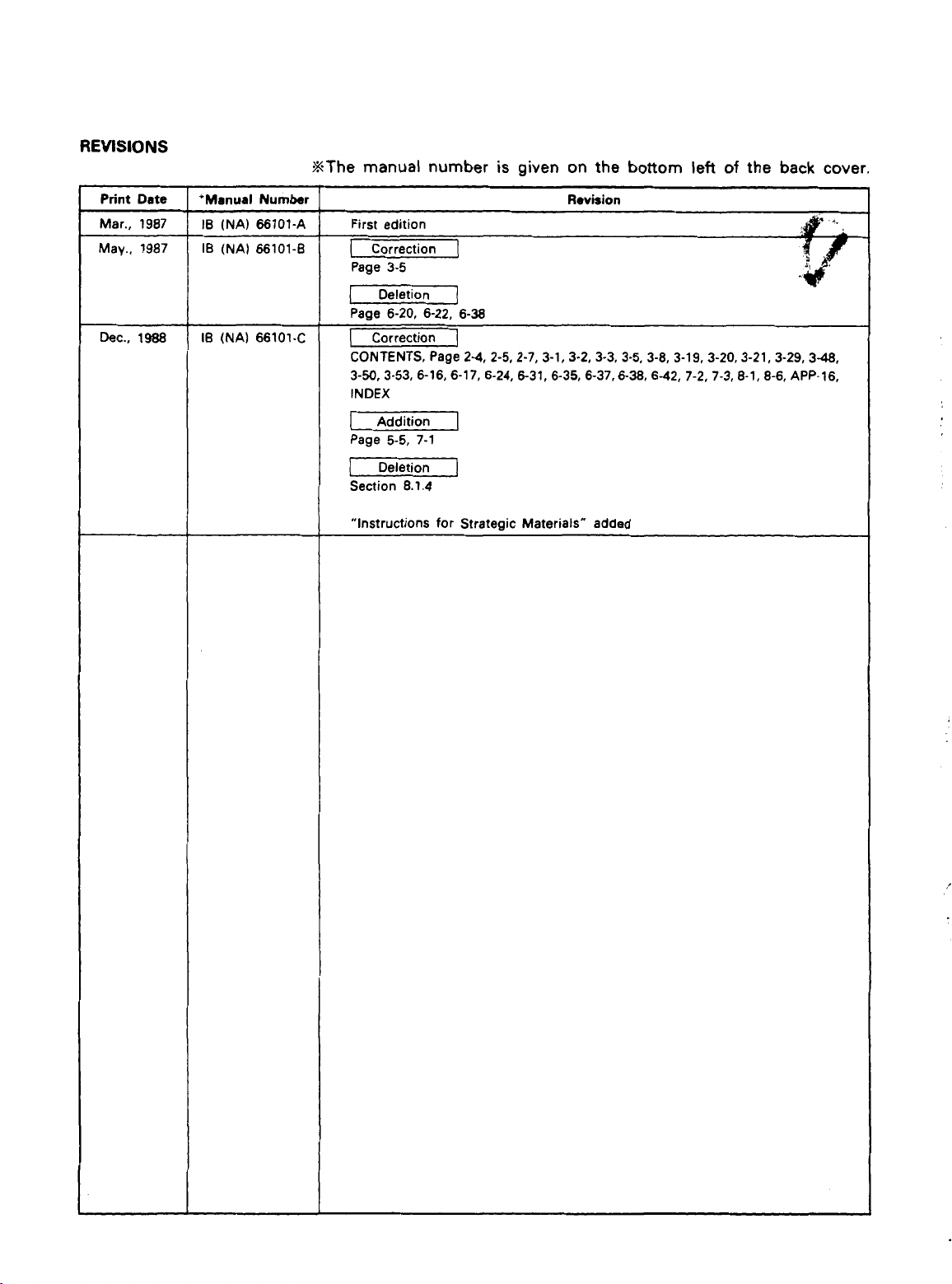
REVISIONS
%The manual number
is
given on the bottom
left of
the back
cover.
Deletion
Section
“Instructions for Strategic Materials”
I
8.1.4
]
added
Page 3

INTRODUCTION
Thank you for choosing the Mitsubishi MELSEC-A Series of General Purpose Programmable
Controllers. Please read this manual carefully
A
copy of this manual should be forwarded to the end User.
so
that the equipment is used to its optimum.
Page 4
2 .
SYSTEM CONFIGURATION
CONTENTS
............................................
2-1 2-7
2.1 Introduction to
2.2 MELSEC-A Series Equipment
2.3 AD71 Programming Equipment
3.1
General Specifications
Performance Specifications and Functions
3.2
3.2.1 AD71 performance specifications.
3.2.2 Functions
3.3
Positioning System Operation
3.3.1 AD71 interfaces
3.3.2 AD71 operation
3.4
Format and Functions of Operating Data
3.4.1 Parameters
3.4.2 Zeroing data
3.4.3 Positioning data
BufferMemory
3.5
3.5.1 Positioning
3.5.2 Error reset (Address 201
3.5.3
3.5.4 Positioning data area
3.5.5 Parameter area
3.5.6 Zeroing data area
1/0 Signals
3.6
3.7
1/0
3.7.1 AD71 electrical specifications
3.7.2 1/0 interface electrical details
Battery Specifications
3.8
OS
(X
(X
(X
Interface with External Equipment
the
AD71
.................................................
....................................................
........................................................
...................................................
...................................................
.......................................................
.....................................................
..................................................
.........................................................
start
data
data (Address 512 to 767)
axis: address 3872 to 5871. Y axis: address 5872 to 7871
axis: address 7872 to 7887. Y axis: address 7892 to 7907)
axis: address 791 2 to 7918. Y axis: address 7922 to 7928)
To
and From
PC
...................................................
2.1
..............................................
.............................................
.....................................
.....................................
..............................................
......................................
..............................................
)
...........................................
.......................................
1
...............
...............
...............
CPU
...........................................
......................................
.......................................
........................................
24
2.7
3.1
3.2
3.2
3-3
3.5
3.5
3.6
3.8
3.8
3-18
3-22
3.29
3-31
3-43
3-43
3-44
3-45
3-46
3-47
3.53
3-53
3-54
3.55
4
.
HANDLING
4.1 Handling Instructions
4.2 Nomenclature
4.3 Preparation
4.3.1 Battery connection
.........................................................
...........................................................
............................................................
4-1 -4-3
.....................................................
.................................................
4-1
4-2
-4-3
4.3
I6
fNA1
56101
C
Page 5
5
.
LOADING AND INSTALLATION
........................................
5-1 %5-6
5.1 Installation Environments
5.2 System Design Precautions
5.3 Installation and Removal
5.4 Wiring
5.4.1 Wiring precautions
5.4.2 Drive unit connector
6
.
PROGRAMMING
6.1 Writing Programs
6.1.1 Program structure
6.1.2 Notes on programming
6.2 Notes on Use
6.3 ACPU Programming
6.3.1 Data
6.3.2 Data communication with
6.3.3
6.3.4
6.3.5 Inching
6.3.6 Position address teaching
6.3.7 Zeroing
6.3.8 Present value change
6.3.9 Positioning stop
6.4 ACPU Remote
6.4.1 Notes on programming
6.4.2 Reading and writing data
6.4.3 Program example
.................................................................
....................................................
........................................................
of
the A6GPP and AD71TU
......................................................
read
and write precautions
Start
positioning
Jog
operation program
.........................................................
.........................................................
1/0
Station Programming
.................................................
.................................................
..................................................
.................................................
...............................................
6-1 5 6-54
..................................................
..............................................
.....................................
.......................................
PC
program
..................................
..................................................
.............................................
............................................
...............................................
..................................................
.....................................
.............................................
...........................................
.................................................
5.1
5-2
5.3
5-5
5.5
5-6
6.1
6.1
6-3
6.5
6.6
6-6
6.7
6-15
6-23
6.25
6.29
6-37
6-39
6.41
6.46
6-46
6-48
6-51
7
.
CHECK
7.1
7.2 Tests and Adjustments
LISTS
General Check List
.......................................................
.......................................................
...................................................
7.2.1 Sequence check
7.2.2 Checking positioning operation
7-1
z7-3
7-1
-7-2
...................................................
.......................................
7.2
7-3
IB
INAI
ffi101.A
Page 6
8
.
TROUBLESHOOTING
................................................
8-1
'v
8-15
8.1 Error Detected by AD71
8.1.1 Data range errors
8.1.2 "HOLD" LED
8.1.3 Buffer memory write errors
8.1.4 AD71 BUSY (positioning) stop errors
8.2 Troubleshooting
8.2.1 General troubleshooting
8.2.2 Drive inoperative
8.2.3 Incorrect positioning.,
8.2.4 Speed wrong
8.2.5 Corrupted positioning data
8.2.6 Unrequested stop
8.2.7 Zeroing fault
9
.
MAINTENANCE
9.1 Unit Storage
9.2 Battery Change
9.2.1 Battery change frequency
9.2.2 Changing the battery
APPENDICES
....................................................
.........................................................
......................................................
............................................................
..........................................................
...................................................
...................................................
.....................................................
...................................................
.....................................................
.................................................
.....................................................
8.1
8.2
8.5
...........................................
...................................
.............................................
.............................................
..........................................
............................................
...............................................
.AP
P.l
8-5
8-6
8.7
8.7
8.8
8.10
8.11
8.12
8.13
8.14
91 9-4
9.1
9.2
9.2
9.4
APP-24
APPENDIX 1 Format Sheets
APPENDIX 2 AD71 Processing Times
APPENDIX 3 System Design Considerations
APPENDIX 4 Connection with Servo Motors
4.1 Connection with Mitsubishi MELSERVO-A
4.2 Connection with Oriental's Pulse Motor
4.3
Connection with Toei Electric's VELCONIC
4.4 Connection with Nikki Denso's DIGITAL S-PACK NDS-300
4.5
Connection with Yaskawa Electric's POSITION PACK-1OA and 10B.APP-15
APPENDIX 5 Dimensions
APPENDIX
INDEX
6
Positioning Data Number
...............................................
........................................
.................................................
and
...................................
...................................
Buffer
...................
......................
..................
Memory Address
......
Conversion Table . .AP P.17
.AP P.10
.AP
.AP P.13
.AP P.14
.AP P.16
.AP
P.1
.AP P.6
.AP
P.7
.AP P.9
P.l
1
IB
INAI
E6101C
Page 7
1.
INTRODUCTION
1.
INTRODUCTION
/MELSEC=A
The AD71
series of programmable controllers. The operation of the position
controller
system by using the extensive MELSEC-A series software features.
This manual covers both hardware and software and contains all the
information required to install and operate the unit to
The manual
Chapter 2 System Configuration
Chapter 3 Specifications
Chapter 4 Handling
is
a
position controller module for use with
may
be
adapted to suit the individual requirements of the
is
arranged
Explains the AD71 operating principles together with
glossary of terms and describes the MELSEC-A series
system configurations suitable for use with the AD71.
Gives the AD71 specifications, functions, a description of
the data required for operation,
external equipment, etc.
AD7 1 nomenclature,
as
follows:
1/0
etc.
the
MELSEC-A
its
optimum.
specifications with
a
Chapter 5 Loading and Installation
Gives AD71 installation and wiring instructions, etc.
Chapter 6 Programming
Explains the
AD71.
Chapter 7 Check Lists
Gives
pre-start-up
Chapter 8 Troubleshooting
Hardware and software fault finding
Chapter 9 Maintenance
Appendices
Gives AD71 dimensions, connection examples with
various servo motors, etc.
PC
programming required to control the
test
procedures.
1-1
IS
INA)
M101-A
Page 8
Refer also to the following manuals:
SWO-AD71P Operating Manual
AGGPP User's Manual
Al, A2, A3CPU
Relevant drive unit instruction manual
In
this
manual,
assume
Packing list:
that the
User's
AD71
AD71
Manual
I/O
numben
is
loaded
assigned
in
slot
0
from
of
the main
the PC CPU
base.
I
40-pin connector
Description
AD71
positioning unit
for
external wiring
I
Quantity
1
1
1
-3
Page 9
2.
SYSTEM
2.
SYSTEM
2.1
Introduction
CONFIGURATKlN
CONFIGURATION
to
the
PC
'C
ACPUl AI
thing unit
'1
AD71
~lse train,
/MELSEC--
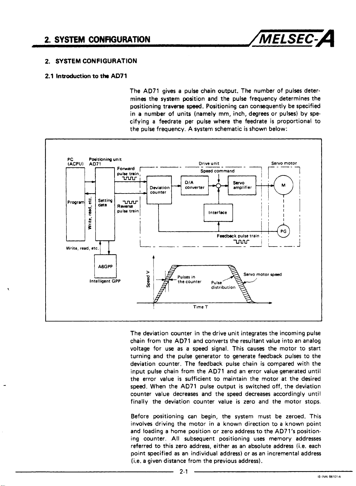
The AD71 gives a pulse chain output. The number of pulses deter-
mines the system position and the pulse frequency determines the
positioning traverse
in a number of units (namely mm, inch, degrees or pulses) by specifying a feedrate per pulse where the feedrate
the pulse frequency. A system schematic
Deviation
'
-
-1unter
r
-
speed.
DIA
converter
Positioning can consequently be specified
is
shown below:
Drive unit Servo motor
Speed command
is
proportional to
1
i
e
AGGPP
Intelligent GPP
i
'I
t
Feedback
>
2
n
ln
it
The deviation counter in the drive unit integrates the incoming pulse
chain from the AD71 and converts the resultant value into an analog
voltage for use
turning and the pulse generator to generate feedback pulses to the
deviation counter. The feedback pulse chain
input pulse chain from the AD71 and an error value generated until
the error value
sped.
counter value decreases and the speed decreases accordingly until
finally the deviation counter value
When the AD71 pulse output
the counter pulse
Time
T
as a speed signal. This causes the motor to
is
sufficient to maintain the motor
pulse train
otor
is
is
switched off, the deviation
is
zero and the motor stops.
I
!
I
I
rpwd
start
compared with the
at
the desired
Before positioning can begin, the system must be zeroed. This
involves driving the motor in a known direction to a known point
and loading a home position or zero address to the AD7l's position-
ing counter.
referred to this zero address, either
point specified
(i.e.
a
given distance from the previous address).
All
subsequent positioning uses memory addresses
as
an absolute address
as
an individual address) or
2-1
as
an incremental address
(Le.
each
I8
(NAI
661014
Page 10
2
SYSTEM
CONFIGURATION
/MELSEC-A
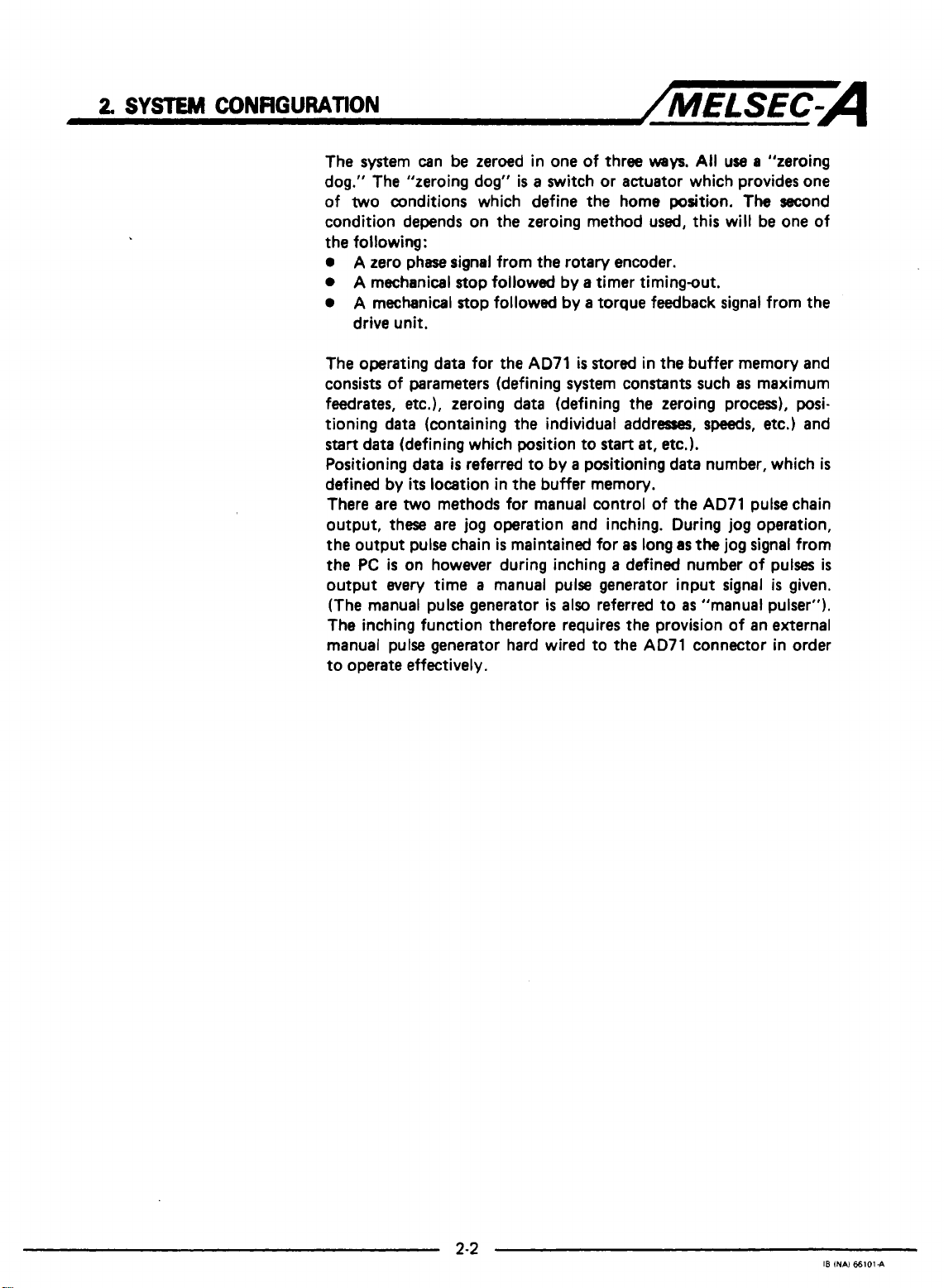
The system can be zeroed in one of three
dog." The "zeroing dog"
of
two
conditions which define the home position.
condition depends on the zeroing method used, this will be one of
the following:
0
A
zero phase signal from the rotary encoder.
0
A
mechanical stop followed by a timer timingout.
0
A
mechanical stop followed by a torque feedback signal from the
drive unit.
The operating data for the
consists
feedrates,
tioning data (containing the individual addresses,
start
Positioning data
defined by
There are
output, these are jog operation and inching. During jog operation,
the output pulse chain
the
output every time a manual pulse generator input signal
(The manual pulse generator
The inching function therefore requires the provision of an external
manual pulse generator hard wired to the
to operate effectively.
of
parameters (defining system constants such
etc.),
zeroing data (defining the zeroing process), posi-
data (defining which position to
is
referred to by a positioning data number, which
its
location in the buffer memory.
two
methods for manual control of the
PC
is
on however during inching a defined number of pulses
is
a
switch
AD71
is
is
maintained for
is
also referred to
stored in the buffer memory and
weys.
All
use a "zeroing
or
actuator which provides one
The
as
maximum
speeds,
start
at,
etc.).
AD71
pulse chain
as
long
as
the
jog signal from
as
"manual pulser").
AD71
connector in order
second
etc.) and
is
given.
is
is
Page 11
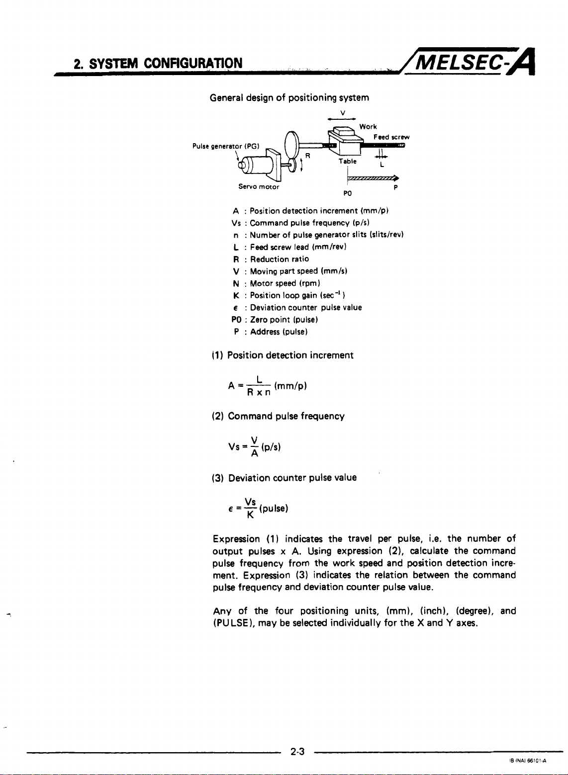
General design of positioning system
Pulse
generator
(PGI
Servo motor
A
:
Position detection increment (mm/p)
Vs : Command pulse frequency (p/s)
:
Number
n
L
:
Feed
R
:
Reduction ratio
V
:
Moving part speed (mm/s)
N
:
Motor speed (rpm)
K
:
Position
E
:
Deviation counter pulse value
PO
:
Zero point (pulse)
:
Address (pulse)
P
(1
)
Position detection increment
(2)
Command pulse frequency
of
pulse generator slits (slitshev)
screw lead (mm/rev)
loop
gain
(sec-'
W
1
P
(3)
Deviation counter pulse value
VS
E
=
-
(pulse)
K
Expression
output pulses
(1)
indicates the travel per pulse,
x
A.
Using expression
i.e.
(2).
calculate the command
the number of
pulse frequency from the work speed and position detection incre-
ment. Expression
(3)
indicates
the
relation between the command
pulse frequency and deviation counter pulse value.
Any of the four positioning units, (mm), (inch), (degree), and
(PULSE), may be selected individually for the X and
Y
axes.
Page 12
2,
SYSTEM
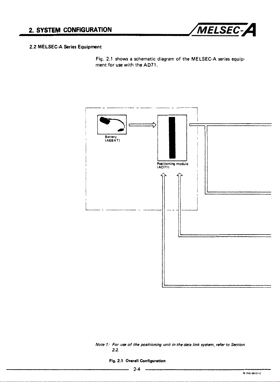
2.2
MELSEC-A Series Equipment
CONFIGURATION
Fig.
ment
2.1
shows a schematic diagram
for
use
with the AD71.
/MELSEC-A
of
the MELSEC-A series equip-
I-
1
Battery
(AGBAT)
I
Positioning
(AD71)
J
module
I
iL
Note
I:
Fig.
For
2.2.
use
2.1
of the
positioning unit in
Overall
Configuration
2-4
the data
link
system,
refer
to
Section
18
INAI
66101C
Page 13
2.
SYSTEM
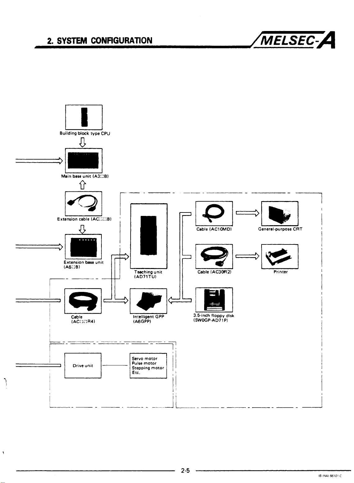
Building
CONFIGURATION
block
type CPU
U
/MELSEC-A
I
Main base unit (A3::B)
I
Extension cable (AC:;::B)
V
-lml&
Extension
(A6;:B)
--I
r-
r--=====-----
d
I
___---
I
Drive unit
n
I
I
'
I
I
I
I
bare
unit
L
Tesching unit
(AD71Tl.J)
1
1
L
I
Intelligent
4qArnI
(A6GPP) (SWOGP.AD71 P)
-
Servo motor
Pulse motor
Pulse motor
Stepping motor
Etc.
u
GPP 3.5inch floppy disk
-7
"
il
-
Printer
L"
I8
INAl
€6101
C
Page 14
.2
SYSTEM
CONFlGURATlON
The
AD71
can
/MELSEC-A
be
used with the following independent
CPUs:
Applicable model
Do
not use the
a
power supply (i.e.
The following
CPU
A1 (E)CPU P21/R21
A2(E)CPU P21/R21
A3(E)CPU P21/R21
A1 (EICPU
A2(E)CPU
A3(E)CPU
AD71
on any extension base which does not include
A5C:B).
types are required for a data link system.
c."
IB
INA)
66101.A
Page 15
2.
SYSTEM
2.3
AD71
CONFIGURATION
Programming Equipment
..
hit
Division
'rogramming
unit
Description
Intelligent
GPP
Plasma handy
programmer
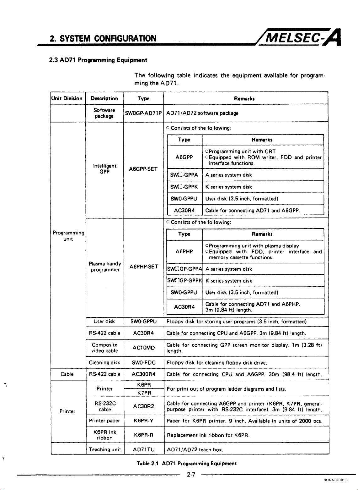
The following table indicates the equipment available
ming the
SWOGP-AD71
AGGPP-SET
AGPHP-SET
AD71.
Remarks
AD7 1 /AD72 software package
P
0
Consists of the following:
OProgramming unit with CRT
1
AGGPP
SWLI-GPPA
SWL2-GPPK
I
WO-GPPU I User disk (3.5 inch, formatted)
I
AC30R4 I Cable for connecting AD71 and AGGPP.
0
Consists of the following:
TYW
AGPHP OEquipped with FDD, printer interface and
SWXP-GPPA A series system disk
OEquipped with
1
interface functions.
A series system disk
K series system disk
OProgramming unit with plasma display
memory
ROM
cassette
writer, FDD and printer
Remarks
functions.
for
program-
I
User disk
RS-422 cable
Composite
video cable
Cleaning disk
Cable RS-422 cable
Printer
RS232C
Printer
cable
Printer paper
KGPR ink
ribbon
Teaching unit
SWO-GPPU
AC30R4
AClOMD
SWO-FDC
AC300R4
KGPR
K7PR
AC30R2
KGPR-Y
KGPR-R
ISW:lGP-GPPKI K series system disk
I
Sk-GPPU 1 User disk (3.5 inch, formatted)
1
AC30R4
1
Floppy disk for storing user programs (3.5 inch, formatted)
~~~~ ~~
Cable for connecting CPU and AGGPP. 3m (9.84 ft) length.
Cable for connecting GPP screen monitor display. lm (3.28 ft)
length.
Floppy disk for cleaning floppy disk drive.
Cable for connecting CPU and AGGPP. 30m (98.4
For print out of program ladder diagrams and lists.
Cable for connecting AGGPP and printer (KGPR, K7PR, generalpurpose printer with RS-232C interface). 3m (9.84 ft) length.
Paper for KGPR printer.
Replacement ink ribbon for KGPR.
AD7 1 /AD72 teach box.
~ ~~
Cable for connecting AD71 and AGPHP.
I
3m (9.84
I
~~~~~~~
ft)
length.
9
inch. Available in units of 2000 pcs.
ft)
length.
I
1
I
Table
2.1 AD71 Programming Equipment
L.
'B
INAi
66101
C
Page 16
3.
SPECIFICATIONS
3.
SPECIFICATIONS
3.1
General
Specifications
/MELSEC-A
I
1-m
Operating amblent
I
temperature
Storage ambient
Operating ambient
hurnidlty
Storage ambient
humidity
resistance
Noise durability
I
wit~~~~~~tqeI
Insulation
resistance
Operating
ambience
Cooling method
I
I
Conforms
JIscosll
SOOV
Frequency
to
10
to 55Hz
55 to
Conforms to JIS C 0912 (109
By noise simulator
IN
noise width and 25 to
AC for 1 rnlnute across DC external terrnlnals and ground
5MR or larger by
Free of corrosive gases. Dust should be rnlnimal.
0
to
55O
c
-20
to 758c
90%RH,
10 to
90%RH,
10 to
Acceleration
150Hz
~ ~~~ ~ ~~~
500V
AC external terrnlnels and ground
noncondensing
non-condensing
~ ~~
Amplitude
0
-
lg
of 15OOVpp noise voltage,
DC lnsulatlon resostance tester across
Self-cooling
075mrn
10
0031nchl 10
-
x
3
times
in
MHz
noise frequency
3
-
Sweep Count
tarn&
'(1 octaveIminuteJ
directions) Shock resinance
I
I
I
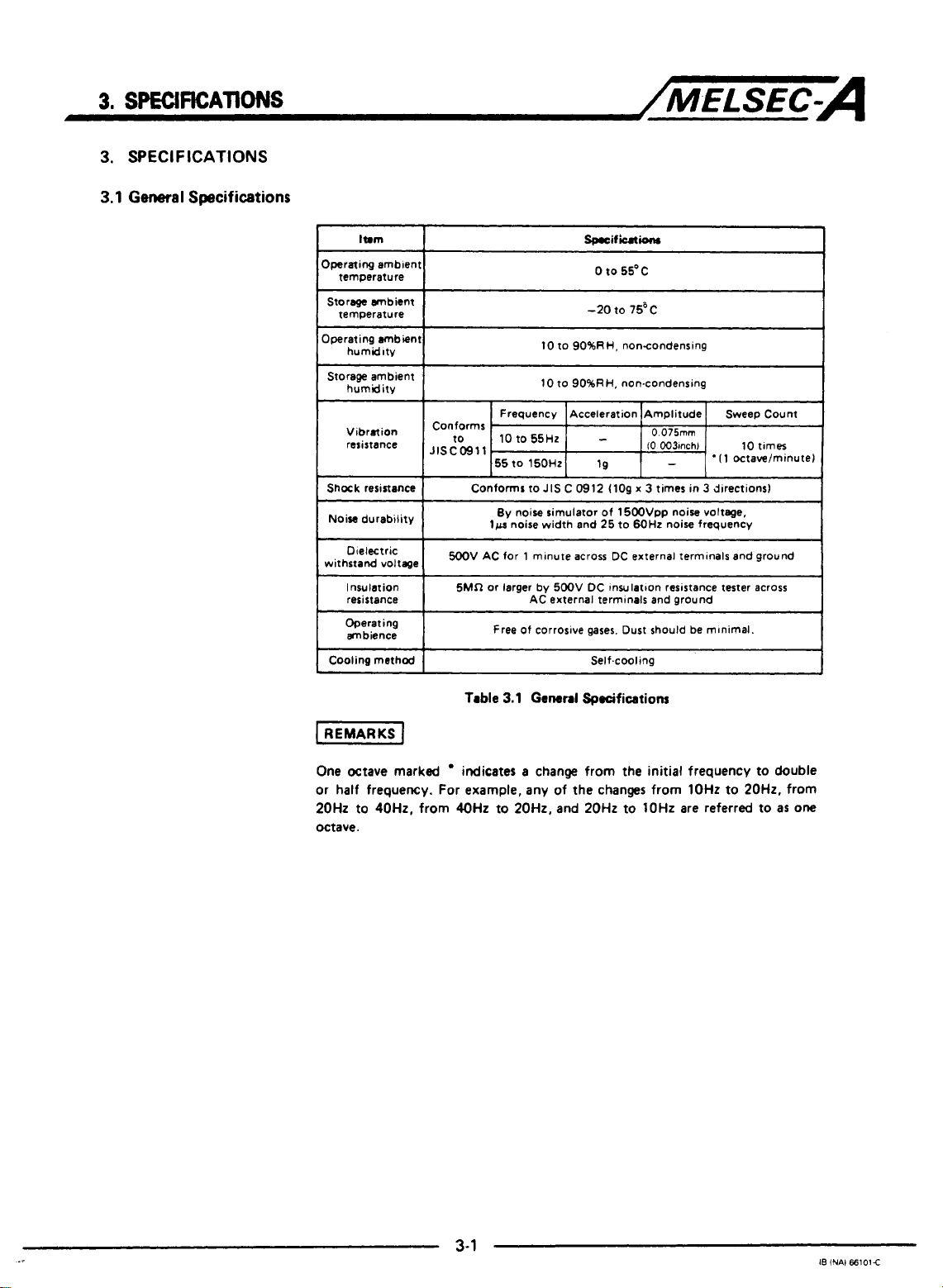
Table
3.1
General
One Octave marked
or half frequency. For example, any
20Hz to 40Hz, from 40Hz to 20H2, and 20Hz to lOHz are referred to as
octave.
indicates a change from the initial frequency
Specifications
to
of
the changes from lOHz to 20H2, from
double
one
3-1
I8
iNAl
66101E
Page 17
3.
SfEClflCAllONS
3.2
Performance Specifications and Functions
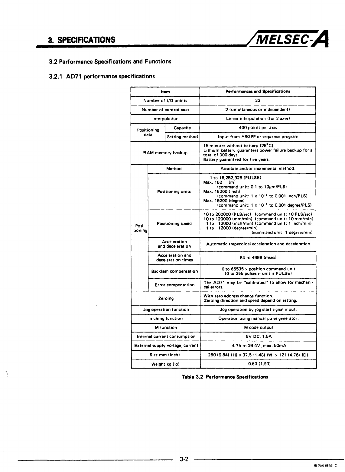
3.2.1
AD71
performance specifications
/MELSEC-A
ltrm
1/0
Number of
Number of control axes
Interpolation
RAM memory backup
-
Posi-
,ionin
deceleration times
Backlash compensation
Error compensation
Jog
operation function
Inching function Operation using manual pulse generator.
M
Internal current consumption
External supply voltage, current
Size
Weight kg (Ib)
points
Method
Positioning units
Positioning speed
Acceleration
and deceleration
Acceleration and
Zeroing
function
mm (inch)
15 minutes without battery 125OC)
Lithum battew guarantees power failure backup for
total of 300 days.
Battery guaranteed for five years.
Max. 162 Im)
Max. 16200 (inch)
Max. 16200 (degree)
10
10 to 12oooO Immlmin) (command unit: 10mm/min)
1 to 12000 (inch/minl (command unit: 1 inch/minl
1 to 12000 (degree/min)
Automatic trapezoidal acceleration and deceleration
The AD71 may
cal
With zero eddrerc change function.
Zeroing direction and speed depand on setting.
Podormanerr
2 (simultaneous or independent)
Linear interpolation (for 2
Input from A6GPP or seguence program
Absolute and/or incremental method.
1 to 16,252,928 (PULSE)
(command unit: 0.1 to 10um/PLS)
(command unit:
(command unit: 1
to
200000
(PLS/sec) (command unit: 10 PLS/sec)
0
to 65535 x position command unit
(0
to
255
errors.
Jog operation by jog start signal input.
4.75 to 26.4V, max. 50mA
and
Specifications
32
~~ ~
400 points per
1
x
lo-'
x
lo-'
(command unit: 1 degreelmin)
64 to 4999 (msec)
pulses if unit
be
"calibrated" to allow for mechani-
M
code
output
DC,
1.5A
5V
0.63 (1.93)
axes)
axis
to 0.001 inch/PLS)
to 0.001 degreelPLS)
is
PULSE)
a
Table
3-2
3.2
Performance Specifications
IS
(NAI
66101C
Page 18
3.
SPECIFKAT1ONS
3.2.2
Functions
~/MELSEC-A
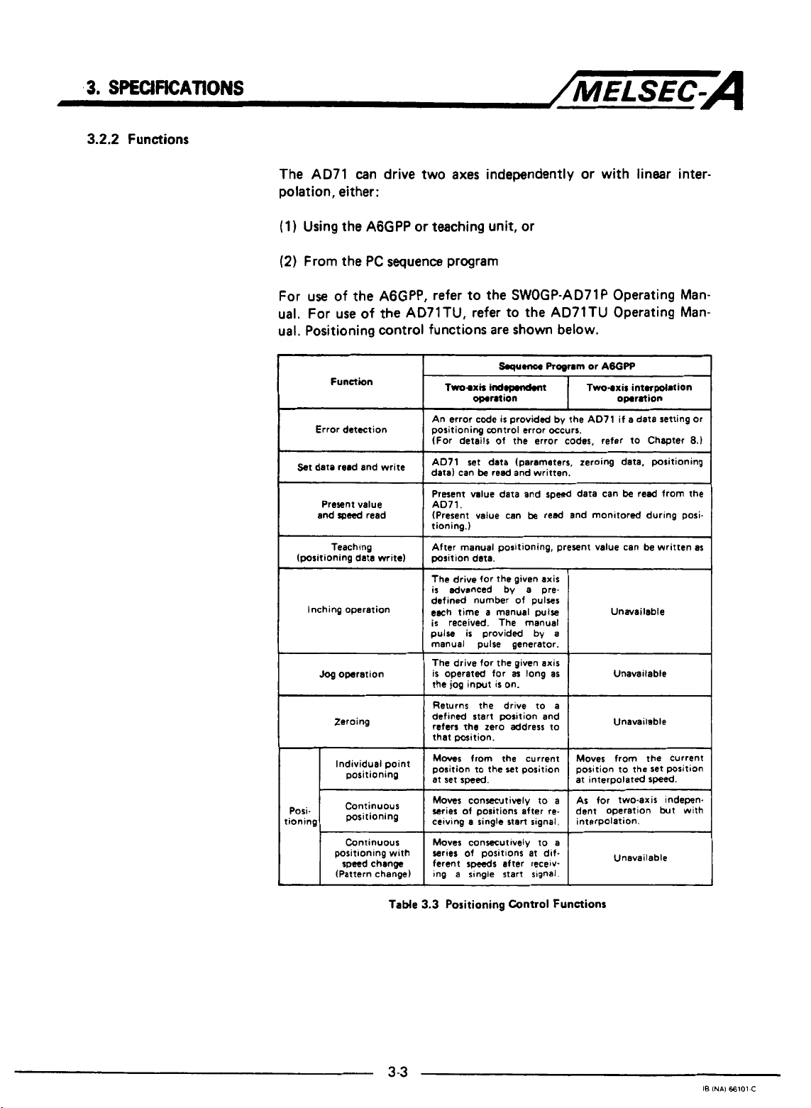
The AD71 can drive two axes independently or with linear interpolation, either:
(1)
Using the AGGPP
(2)
From the PC sequence program
For
use
of the AGGPP, refer to the SWOGP-AD71P Operating Manual. For use of
ual. Positioning control functions are
Function
Error detection
st
date
and
(positioning data mite)
Inching operation
and
Present value
speed
read
Teaching
Jog
operation
Zeroing
positioning
or
teaching unit, or
the
AD71TU, refer to the AD71TU Operating Man-
write
point
shown
~~
Squmce
Trm-axir
An error code
positioning control error occurs.
(For details of the error codes, refer to Chapter
I
AD71 set data (parameters, zeroing data, positioning
data) can
Present value data and
AD71.
(Present value can
tioning.)
After manual positioning, present value can be written as
position data.
The
is
defined number
each time a manual pulse
is
pulse
manual pulse generator.
The drive for the given axis
is
operated for
the
1
Returns the drive to a
defined start position and
refers the zero address to
I
that position.
Moves
position to the set position
set
at
indopmndmt
omntion
is
provided by the AD71 if a data setting or
be
read and written.
drive for the given axis
advanced by a pre-
received. The manual
is
provided by
from
is
on.
the
a~
jog
input
speed.
below.
Progrm
or
ABOPP
Two-axir intorpolation
omration
~~
~~~ ~~
speed
data can
be
reed and monitored during posi.
of
pulses
a
long
as
be
Unavailable
Unavailable
I
I
current
Unavailable
Moves from the current
position to the set position
at interDolated
read from
8.)
the
speed.
Posi-
tioning
Continuous
positioning
Continuous
positionlng with
speed change
(Pattern change)
TaMe
3
-3
series of positions
speeds
ferent
Ing
a single start slgnal.
3.3
Positioning
at
dif-
after recetv-
Control
Functions
Unavailable
I8
INAI
66101-C
Page 19
3.
SPECIFICATIONS
Note
I.
1:
Error compensation and backlash compenmtion functions are valid
for all the functions shown in Table
2:
An indexed code may
amciated processes during positioning. This
code.
3:
The
A071
present value can be rewritten before positioning
using the sequence program or AGGPP.
4:
Positioning
writing positioning start data to the buffer memory
39,
Y
axis:
may
300
to
be
used
be
executed continuously for up to
339).
/MELSEC-A
3.3.
as a digital signal for the control of
is
known as an
is
20
points by
(X
axis: 0 to
"M"
s?a,-ted
3-4
IB
INAJ
66101-A
Page 20
3.
SPECWICATIONS
3.3
Positioning
3.3.1
AD71
System Operation
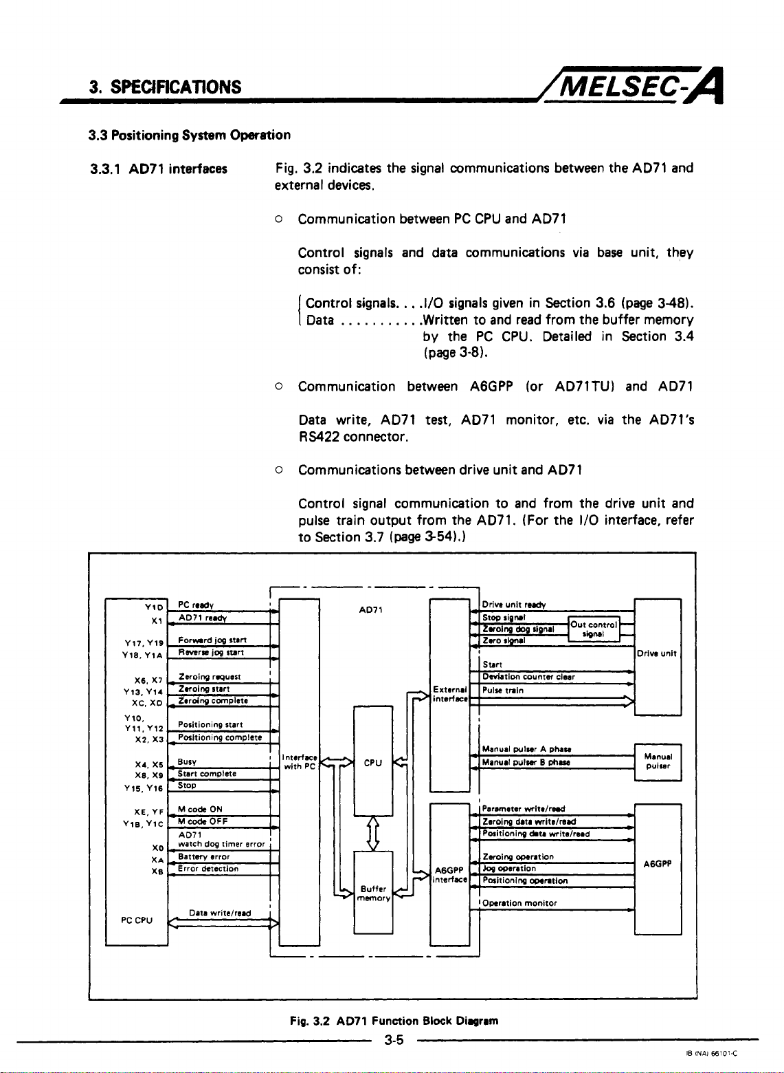
interfaces Fig, 3.2 indicates the signal communications between
external devices.
o
Communication between
PC
CPU and AD71
/MELSEC-A
the
AD71
and
Control signals and data communications
consist of:
Control signals.
Data
I
0
Communication between A6GPP (or AD71TU) and AD71
Data write, AD71
RS422
o
Communications between drive unit and AD71
Control signal communication to and from the drive unit and
pulse train output from the AD71. (For the
to Section 3.7
. . .
connector.
. . .
.
,
.I/O signals given in Section 3.6
.
.
. .
.Written to and read from the buffer memory
by the
(page
test,
(page
3-54).]
PC
CPU. Detailed in Section 3.4
3-81.
AD71 monitor,
via
base unit, they
(page
etc. via
the AD7l's
1/0
interface, refer
348).
PC
I
CPU
Data writelread
II-
Fig.
3.2
AD71
Function
3-5
-1
Block Diagram
IB
INAl
€6101-C
Page 21
3.
SPECIFICATIONS
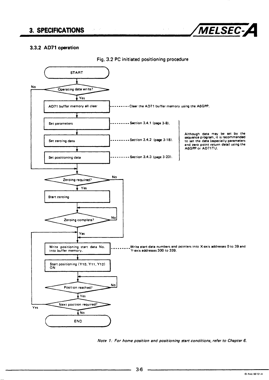
3.3.2
AD71
operation
START
u
AD71 buffer memory all clear
+
Yes
Fig.
3.2
-
PC
initiated positioning procedure
-
- - - - -
--Clear
the
AD7 1 buffer memory using the AGGW.
/MELSEC-A
Set
parameters
Set
zeroing data
Set
positioning data
I
Start zeroing
*
I
I
I
Write positioning start
into buffer memory.
Start positioning (Ylo, Yll,Y121
4
+
I
Zeroing required?
Zeroing complete?
L-
data
---------Section 3.4.1 (page3-8).
.
- -
-.
-
--Section 3.4.2
-
- -
-
-
- - -
-
Section 3.4.3 (page 3-231.
1
No.
Write start data numbers and pointers into X-axis addresses 0 to 39 and
Y-axis
addresses
I
(pe
3.1 81.
300 to 339.
Although data
sequence progrm,
to
set
the data (especially parameters
zero
and
AGGPP or AD71TU.
may
it
is
point return datal using the
be
set
bv
recommended
the
Note
I:
For home position and positioning
1-
start
conditions, refer to Chapter
6.
IB
INAI €6101-A
Page 22
3.
SPECIFICATIONS
/MELSEC-A
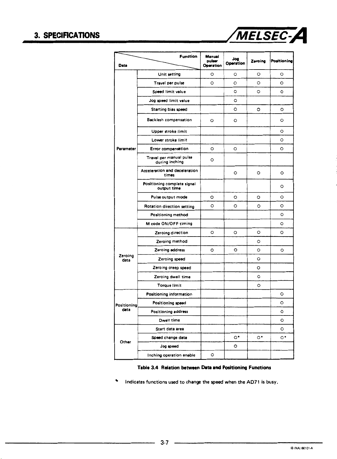
Acceleration
and
deceleration
Table
3.4
Relation
Indicates functions used to change the
between
Data
3-7
md
Positioning
speed
when the
Functions
AD71
is
busy.
18
(NAI
66101-A
Page 23
3.
SPECIFICATIONS
3.4
Format and Functions
!
of
Operating Data
/MELSEC-A
3.4.1
Parameters
The following three blocks of data
the AD71. This data
explained in Section
o
Parameters
o
Zeroing data
o
Positioning data
Operating data
1)
AGGPP or AD71TU.
2)
Sequence program.
It
is
necessary to
This
is
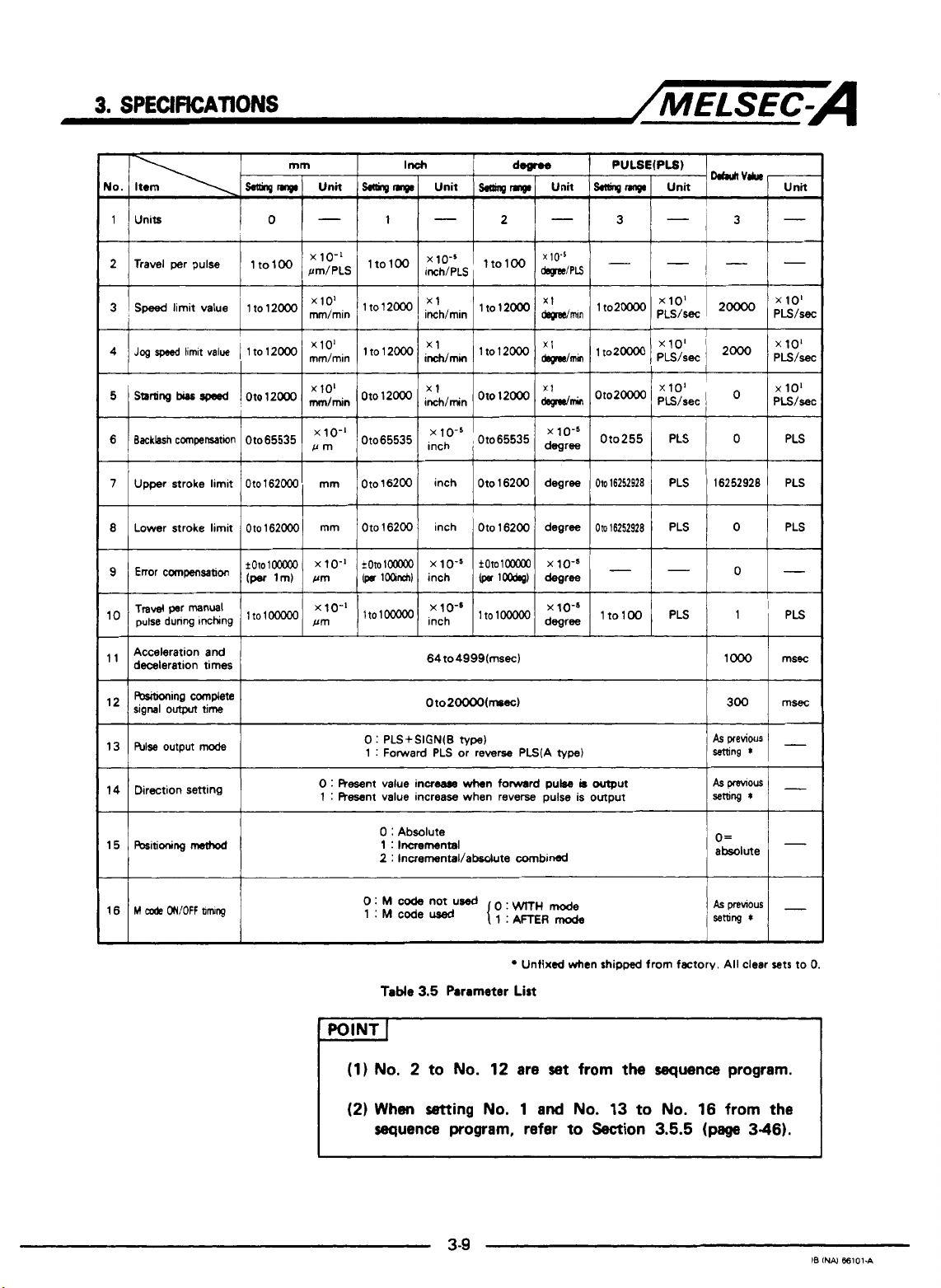
the general information required for positioning. Table
gives
a
list
of all the parameters which must be
Initial parameter values
is
written to the buffer memory which will be
3.5
(page
is
written using:
. .
.
.
set
data for the two
3-30).
.For details, refer to the SWOGP-AD71P
or AD71TU Operating Manual.
.
.For details, refer to Chapter 6.
are
required for positioning using
axes
(X
and
Y
1.
set
for the AD71.
3.5
If parameters are not
is
outside the allowed
shown in Table
the buffer memory.
Parameters are checked when:
1)
the
power
is
2)
parameters are transferred from the A6GPP to the AD71;
3)
"PC
ready signal" from the
"off"
to
"on"; or
4)
(1) zeroing,
been selected in A6GPP
Error code and error detection signal are not given for the "power on"
parameter check.
set
or
setting
3.5
and the faulty
switched on;
(2)
positioning,
an error
range),
PC
(3)
test
mode.
is
found (for example parameter
all
data defaults to the values
set
of parameters will remain in
CPU to
jog operation, or
the
AD71 switches from
(4)
inching has
3-8
IB
INAl
66101-C
Page 24
3.
SPECIFICATIONS
2 Travel per pulse
x
/MELSEC-A
10-5
3
Speed
limit value 1 to 12OOO lt012000
~
I
'
5
starting
bias
rpesd I Oto 12000 oto12MX)
6 Backlashcompenration 01065535
7
Upper stroke limit Oto162000 mm Oto16200 inch Oto16200 degree
~~~ ~ ~ ~
8
Lower stroke limit
Acceleration and
deceleration times
I
R&itioning complete
signal
outpn
hlse
13
output
Oto
time
mode
xlol
mm,min
x 101 x1
,"Ao-'
Oto65535
162ooO mm Oto 16200 inch
0
1 : Forward PLS or rewrse PLS(A
zh,min
ih,min
i::{-5
Oto20000(mssc)
:
PLS+SIGN(B
lto12000
Oto
,
Oto65535
1
Oto
type)
12000
16200 degree
x1
wmin
xlo's
mree
type)
OtoZm
Or0255 PLS
Oto16252928
Om16252928
x 10'
PLS/sec
PLS 16252928
PLS
0
I
0
0
15
bitioning
method
0
:
Resent value increase
:
Resent value increaw when reverse pulse is output
1
0
:
Absolute
1
:
Incremental
2
:
Incrernental/absdute combined
0:
M
code
1:Mcoded
Table
not
3.5
wtmn
forward
used
o:
Parameter
pulse
WrrH
mode
Unfixed when
List
-
POINT
(1)
No,
(2)
When
sequence
I
2 to
No.
setting
program, refer
3-9
12 are
No.
1
set
and
No.
to
b
output
shipped
from
Section
from factory. All clear sets
the
sequence
13
to
No.
16 from
3.5.5
(page
absolute
O=
program.
3-46).
I-
to
0.
the
IB INN
ffi101.A
Page 25
3.
SPECIFICATIONS
/MELSEC-A
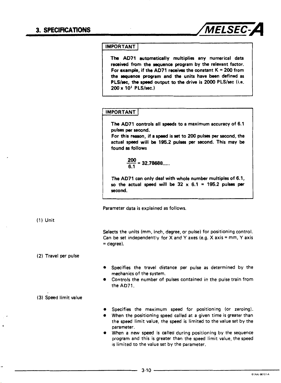
IMPORTANT
The AD71 automatically multiplies any numerical data
received from
For
example,
the
sequence
PLS/sec,
200
x
I
IMPORTANT
The
AD71 controls
pulses
For
this
actual
found
The AD71 can only deal with whole number multiples of 6.1,
so
the
second.
I
the
sequence program
if
the
AD71 receives the constant
program
the
sped
output
10'
PLS/wc.)
I
all
per
second.
rearon,
speed
as
follows
200
-
6.1
actual speed will
if
will
=
32.78688
a
speed
be
and
the
to
speeds
is
set
195.2
pulses
.....
be
by
the
relevant factor.
K
=
units have been defined
the drive
to a maximum accuracy of 6.1
to
32 x 6.1 = 195.2 pulses
is
2000 PLS/sec
200
pulses per second, the
per second. This may
200 from
as
(Le.
be
per
(1)
Unit
(2)
Travel per pulse
(3)
Speed limit value
Parameter data
Selects
Can be
=
0
0
0
0
0
the units (mm, inch, degree, or pulse) for positioning control.
set
degree).
Specifies the travel distance per pulse
mechanics of the system.
Controls the number of pulses contained in the pulse train from
the
AD71.
Specifies the maximum speed for positioning (or zeroing).
When the positioning speed called
the speed limit value, the speed
parameter.
When a new speed
program and this
is
limited to the value
is
explained
independently for X and
as
follows.
is
called during positioning by the sequence
is
greater than the speed limit value, the speed
set
by the parameter.
Y
axes
(e.9. X axis = mm,
as
determined
at
a
given time is greater than
is
limited to the value set by the
Y
by
axis
the
3-1
0
IS
INAI 66101-A
Page 26
(4)
Jog speed limit value
(5)
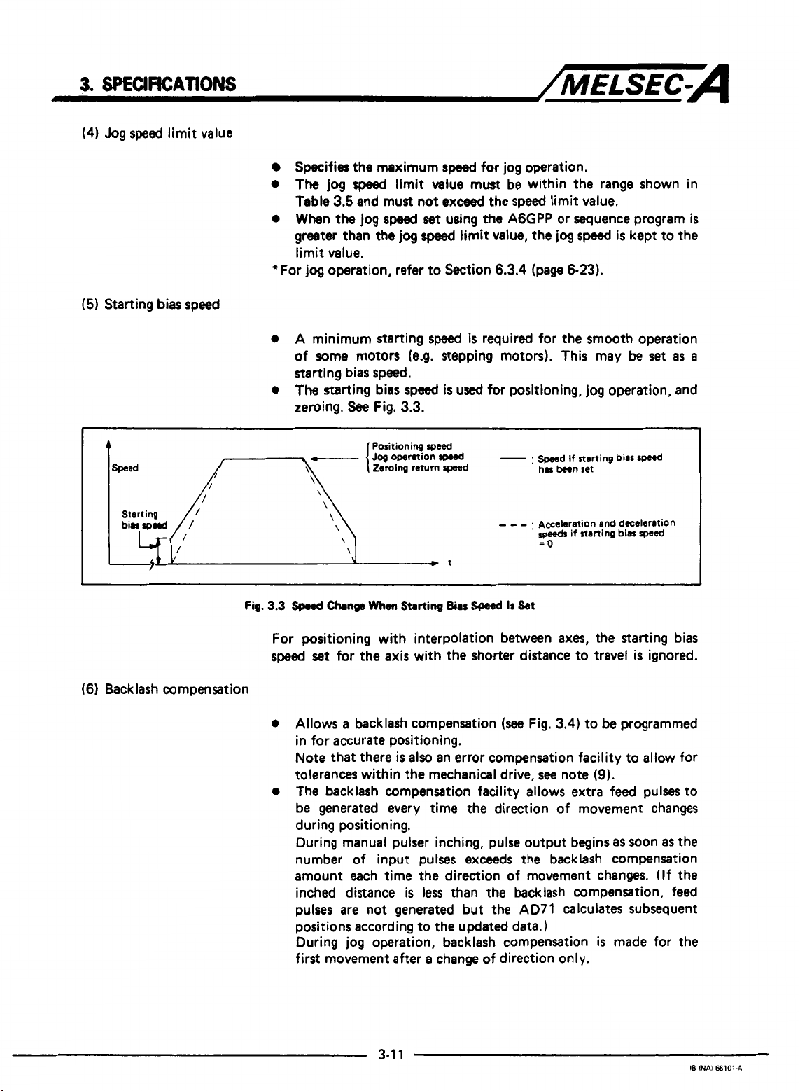
Starting
Starting
bias speed
Sptxifies
0
The
Table
0
When the jog
greater than
the
jog
sped
3.5
and must not
maximum
limit value must
speed
set
the
jog
speed
speed
for jog operation.
exceed
using
the
the
limit value,
be
within the range shown in
speed
limit value.
A6GPP or sequence program
the
jog
limit value.
*For
jog
operation, refer to Section
0
A minimum starting
speed
6.3.4
(page
is
required for the smooth operation
of some motors (e.g. stepping motors). This may be
starting bias speed.
0
The
starting bias speed
zeroing.
See
\
\
\
\
\
\
Fig.
3.3.
Positioning
Zeroing return speed
is
used for positioning,
speed
-.
- - -
t
.
has
been set
Aseleration and dcelrration
speeds
=o
speed
is
6-23).
jog
operation, and
if starting bias
if starting bias
kept to the
set
as
sped
spa&
is
a
I
(6) Backlash compensation
Fig.
3.3
spnd
Change
When
Starting
Bias
W
Is
For positioning with interpolation between axes,
speed
set
for the axis with
0
Allows a backlash compensation
the
shorter distance to travel
(see
in for accurate positioning.
Note that there
tolerances within
0
The backlash compensation facility allows extra feed pulses to
is
also
an error compensation facility to allow for
the
mechanical drive,
be generated every time the direction of movement changes
during positioning.
During manual pulser inching, pulse output begins
number of input pulses exceeds the backlash compensation
amount each time the direction of movement changes.
inched distance
pulses are not generated but
is
less
than the backlash compensation, feed
the
positions according to the updated data.)
During jog operation, backlash compensation
first movement after a change of direction only.
kt
the
starting bias
is
ignored.
Fig.
3.4)
to be programmed
see
note
(9).
as
soon
as
(If
AD71 calculates subsequent
is
made for the
the
the
Page 27
3.
SPECIFEATWNS
'-s,
/MELSEC=A
.
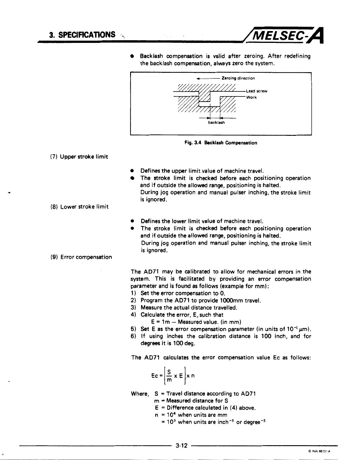
(7)
Upper stroke limit
(8)
Lower stroke limit
(9)
Error compensation
Backlash compensation
the backlash compensation, always zero the system.
I
Fig.
0
Defines
The stroke limit is checked before each positioning operation
and if outside the allowed range, positioning
During jog operation and manual pulser inching, the stroke limit
is
0
Defines the lower limit value of machine travel,
0
The stroke limit
and if outside the allowed range, positioning
During jog operation and manual pulser inching, the stroke limit
is
the
ignored.
ignored.
upper limit value of machine travel.
is
valid after zeroing. After redefining
f--
-+t-+--
3.4
is
checked before each positioning operation
backlash
Backlrsh
Zeroing
direction
Lead rrew
Work
Cornpansation
is
halted.
is
halted.
The AD71 may be calibrated to allow for mechanical errors in the
system. This
parameter and
1
)
Set
the
2)
Program the AD71 to provide lOOOmm travel.
3) Measure the actual distance travelled.
4)
Calculate the error,
E
5)
Set
E
6)
If using inches the calibration distance
degrees
The AD71 calculates the error compensation value Ec
Ec=
Where,
is
facilitated by providing an error compensation
is
found
as
follows (example for
error compensation to
E,
such that
=
lm - Measured value. (in
as
the error compensation parameter (in units of 10-lpm).
it
is
100 deg.
-x€
I:
S
=
Travel distance according to AD71
m = Measured distance for
E
=
Difference calculated in
n
=
lo4
=
10'
xn
I
when units are mm
when units are inch-' or degree-'
0.
mm)
S
(4)
above.
mm):
is
100 inch, and for
as
follows:
3-1
2
IB
INAI
66101-A
Page 28
3.
SPECWICATIONS
/MELSEC-A
Error compensation
positioning applications.
Backlash compensation, Bc, should
expression:
where,
(1
0)
Manual pulser inching travel increment
0
0
0
(1
1 ) Acceleration and deceleration times
0
is
valid for: manual pulser inching, jogging and
be
set according to the following
Bc=BxE
B
=
Actual backlash
E
=
As above
Defines the distance travelled each time a manual pulser inching
command
is
given.
The AD71 counts the number of manual pulser inching commands input and transmits the appropriate number of output
pulses.
During manual pulser inching there
(The
speed
is
fixed
at
2oooO
PLS/sec.)
is
no automatic acceleration/
deceleration.
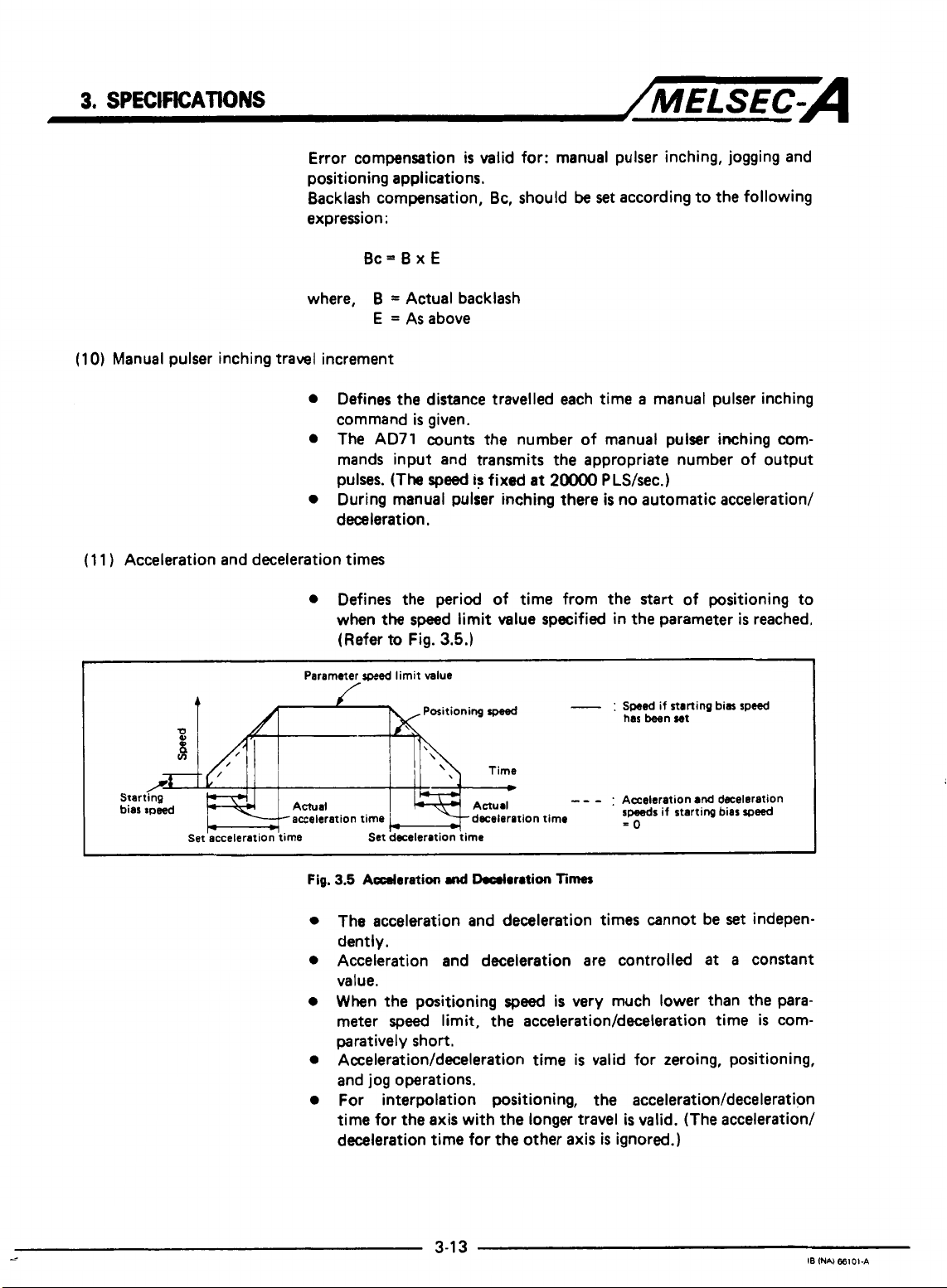
Defines the period of time from the start of positioning to
when
the speed limit value specified in the parameter
(Refer to
Fig.
3.5.)
is
reached.
Parameter
4
0,
8
v)
/*
Starting
bias speed Actual
*
Set acceleration time Set deceleration time
-acceleration
Fig.
speed
limit value
-
:
Swed
if starting bias speed
has been set
Acceleration
speeds
if starting bias
-0
time -deceleration time
3.5
Adoration
Positioning
md
Ikcrlaration
speed
-
Times
- -
The acceleration and deceleration times cannot be
dently.
Acceleration and deceleration are controlled
value.
When the positioning
meter
speed
limit, the
speed
is
very much lower than the para-
acceleration/deceleration
paratively short.
Acceleration/deceleration
time
is
valid for zeroing, positioning,
and jog operations.
For interpolation positioning, the
time for the axis with the longer travel
deceleration time for
the
other
axis
acceleration/deceleration
is
valid. (The acceleration/
is
ignored.)
and
deceleration
set
at
time
speed
indepen-
a
constant
is
com-
3-1
--
3
IB
INN
€6101-A
Page 29
3.
SPECIFICATIONS
(1
2)
Positioning complete signal duration
(1
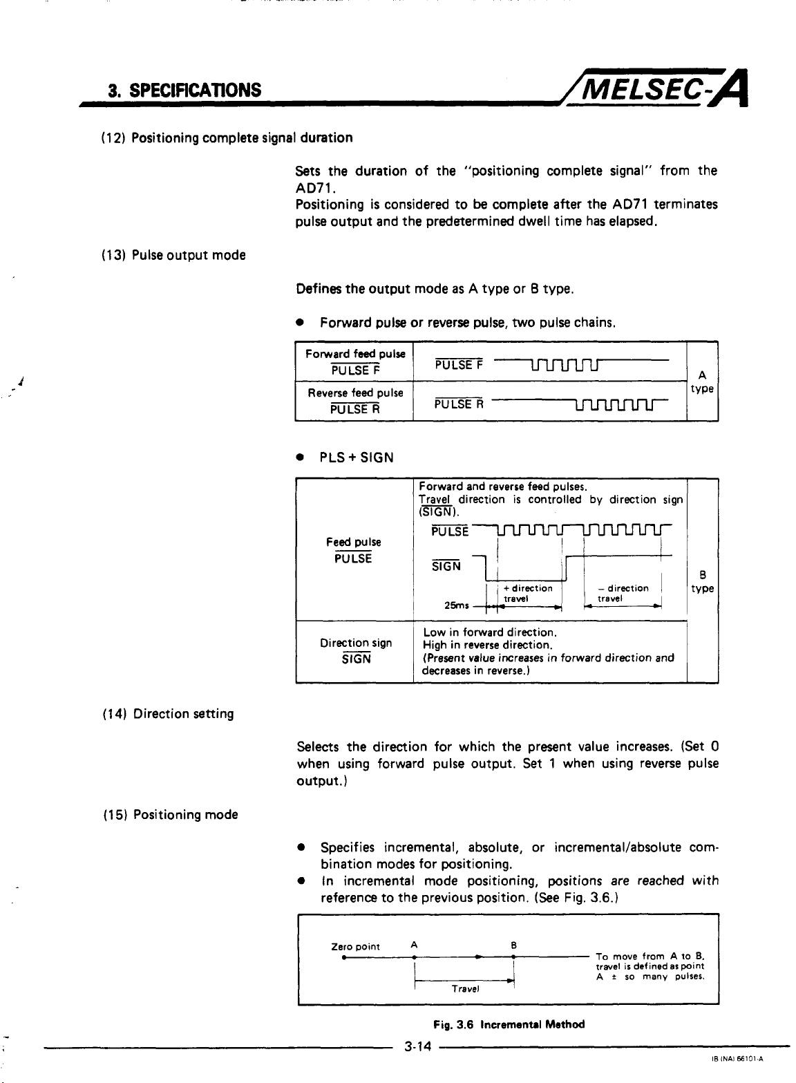
3)
Pulse output mode
/MELSEC-A
Sets the duration of the "positioning complete signal" from the
AD71.
Positioning
pulse output and the predetermined
is
considered to
be
complete after the
dwell
AD71
time has elapsed.
terminates
Defines the output mode
0
Forward pulse or reverse
0
PLS+
SIGN
Forward and reverse feed pulses.
Travel
(SIGN).
I
Direction Sign
slGN
I I
Low
High
(Present
decreases in reverse.)
as A type or 8 type.
pulse,
two
pulse chains.
direction
in forward direction.
in
reverse direction.
value increases
is
controlled
in
forward direction and
by
direction sign
I
(1
4)
Direction setting
(15)
Positioning mode
Selects
when using forward pulse output.
output.
the direction for which the present value increases.
Set
1
when using reverse pulse
)
(Set
0
Specifies incremental, absolute, or incrementaVabsolute combination modes for positioning.
0
In incremental mode positioning, positions
reference to the previous position.
Zero
point
.-
A
3-14
Fig.
-
3.6
Incremental
B
(See
Method
Fig.
are
3.6.)
To
move
travel
A t so
reached with
from
defined
many
A to
as
point
pulses.
is
6.
IB
INAl
66101-A
Page 30
3.
SPECIFKATIOMS
/MELSEC=A
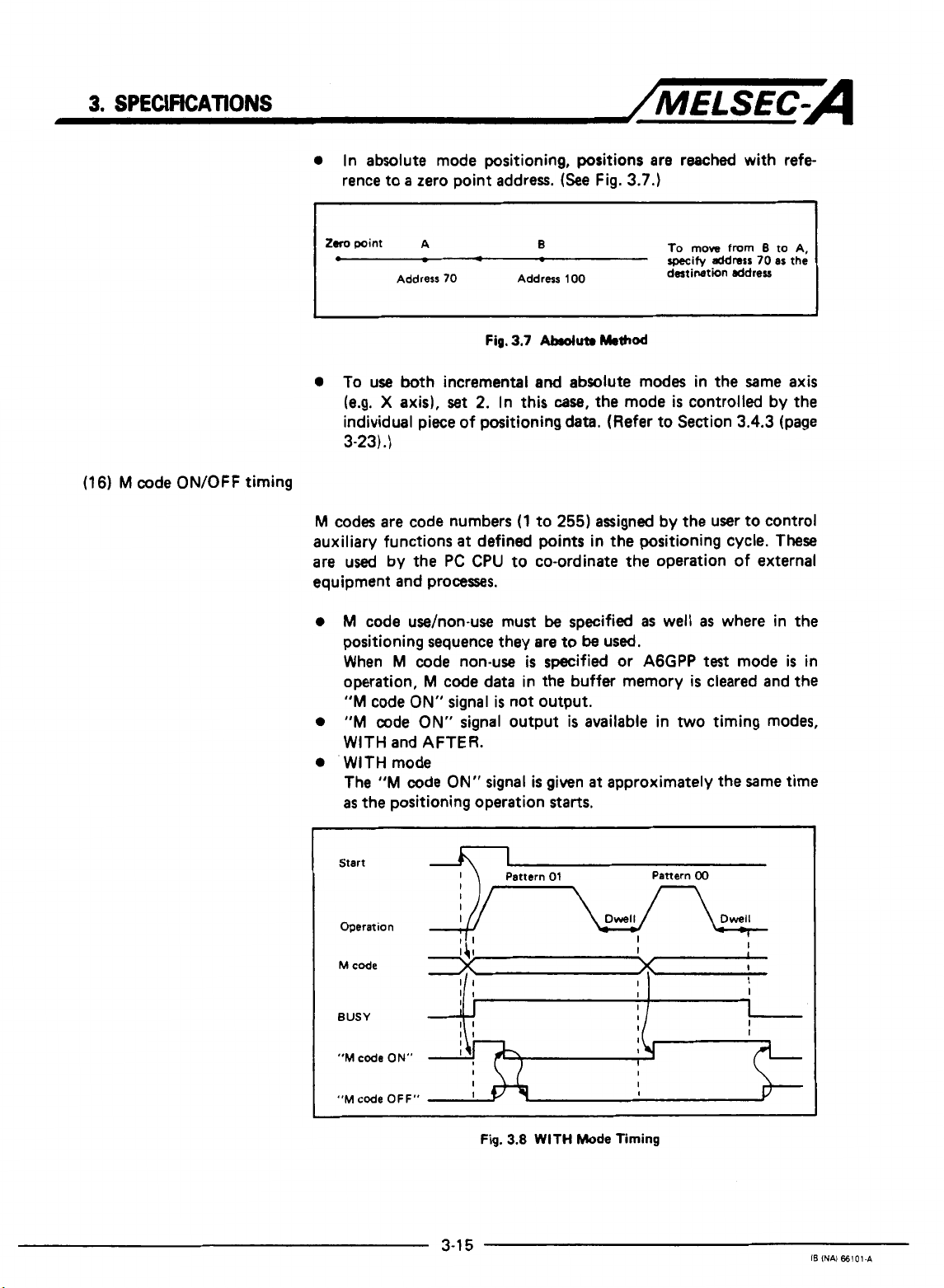
0
In absolute mode positioning, positions are reached with refe
rence to a zero point address.
(See
Fig.
3.7.)
(16) M code ON/OFF timing
1
tom
point A
0
0
To use
(e.g. X axis),
Address
both
-
70
Fig.
incremental
set
2.
individual piece of positioning data. (Refer to Section
3-23)
.)
M
codes are code numbers
auxiliary functions
are used by the
at
defined
PC CPU
equipment and processes.
0
M
code
use/non-use must
positioning sequence they are to
When M code non-use
operation, M code
"M
code
ON"
0
"M
code
ON"
data in the buffer memory
signal is not output.
signal output
WITH and AFTER.
0
WITH mode
The
"M
code
ON"
signal
as
the positioning operation
B
Address
100
3.7
Abduta
and
absolute modes in the Same axis
In
this
case,
(1
to
255)
points
to co-ordinate
be
specified
be
is
specified or
is
is
given
starts.
Method
the mode
assigned by the user to control
in the positioning cycle.
the
operation of external
as
used,
A6GPP
available in
at
approximately the Same time
To
move
specify
destination ddreu
is
from
address
70
controlled by the
3.4.3
well
as
where in the
test
mode
is
cleared and the
two
timing modes,
B
to A,
as
(page
These
the
is
I
in
I
Start
Operation
"M
code
"M
code OFF"
ON"
3-1
I
I
I
I
I
I
5
Fig.
3.8
WITH
Mode
Timing
Pattern
00
IB
INAI
66101.A
Page 31

3.
SPECIFICATIONS
0
AFTER
The
has finished. In this mode, if the operation
complete the
I
Start
"M
mode
code
ON"
"M
signal
code
is
ON"
given
signal
/MELSEC-A
after
the positioning operation
is
is
not given.
stopped before
it
is
Operation
M
code
BUSY
"M
code
ON"
"M
code
OFF"
POINT
I
0
The
"M
in
the
0
The
M
and the
the
positioning pattern, refer to Section
3-23)
.)
The next positioning operation
code ON" signal
An error condition arises if the
at
the rise of the
started. The
I,
II
I
I1
11
Fig.
code
ON"
positioning data
code
is
ignored if the positioning pattern
"M
code
is
"M
01
Pattern
3.9
AFTER
signal
is
is
set
ON" signal
switched
start
code
ON"
Pattern
00
I]
I
x
x
if
I
I
Mode
Timing
not
given
if the
M
code
at
0.
is
not given, (For details of
3.4.3
is
not started until
off.
"M
code
ON" signal
signal and positioning
signal
is
turned
off
I
is
"11"
(page
the
is
is
when:
data
"M
on
not
_.
1.
"M
code
2.
PC
ready signal
3.
Zeroing, positioning,
is
selected
3-1
6
OFF" signal changes from
(Y
1D)
is
off;
or
jog
operation, or inching mode
in
the AGGPP
test
mode.
OFF
to ON;
I6
INAl
€6101-A
Page 32

3.
SPEClFKATlONS
/MELSEC-A
M
code
BUSY
"M
code
(WITH
mode)
"M
code
(AFTER
ON"
ON"
mode)
For a sequence of positions, the first of which are defined
pattern
"00" or
itself
I
I
I
is
"1 1
"01"
given
",
the
pattern data
at
"M
code
ON"
signal is not given until the first
is
reached. In this
case
the M code
the first position. This is illustrated below.
Pattern
00
Dwell
-
I'
1
I]
I
I
\,
I
as
"M
code
OFF"
Fig.
3.10
"M
code
ON"
Simrl
Timing
for
Positioning
haern
"1
1"
Page 33

3.
SPECIFICATIONS
3.4.2
Zeroing
data
/MELSEC=A
1
Zeroing direction
2
Zeroing method
4
I
Zeroing speed
~
1
to 12000
This defines a home position or zero point for
Table
3.6.
Zeroing data
1)
parameters or zeroing data
AD71;
2)
"PC
from
3)
zeroing, positioning, jog operation, or manual pulser inching
selected in
I
x101
I
mm/min
is
checked when:
ready
signal"
OFF
to
AGGPP
0
:
1
:
0
:
1
:
2
:
to
is
transferred from the
output from the
ON;
or
test
mode.
Forward direction(address increases)
Reverse direction(address decreases)
Pulse generator(PG1zero-point signal
Stop and dwell timer time-out
Stop and signal from drive unit
l2Oo0
1
inch/rnin
x1
I
lo
PC
l2OO0
~
deg/min
x1
CPU
the
to the
I
to2m
AD71.
A6GPP
AD71
Refer to
to the
changes
I
PLS/sec
xlol
is
to
2000
inch/rnin
~
x1
Zeroing Data
to
No.
Oto499(
1
7
No.
time
7
Torque limit
TsMe
3.6
I
POINT
J
(1)
NO.
3
(2)
When setting
gram, refer to Section
0
to
can
1
to
l2OoO deg/min
i
x
10'msec)
2
50(%)
be
set
and
No.
3.5.6
(WW
'
I
x1
by
the sequence program.
2
from
to20000
I
the
sequence Pro-
3-47).
PLS/sec
I
xlol
1
3-18
IB
lNAl 66101.A
Page 34

3.
SPECJFtCATlONS
/MELSEC-A
(1
Zeroing direction
(2)
Zeroing methods
Zeroing data
is
explained below:
Specifies the direction for zeroing.
IMPORTANT
Zetoing
speed.
Always
1
is
controlled according
Deceleration
ensure
that
is
the
to
the zeroing direction and
started when an actuator
zeroing
direction
is
correct for
is
drive system used.
Zero the system using one of the following methods,
require a "zeroing dog" or actuator to reduce the
speed
speed.
a)
Zero-phase signal from pulse generator
b)
Stop and dwell timer time-out
c)
Stop and signal from drive unit
(a)
Zero-phase signal from
PG
(PG)
operated.
the
all
methods
to the creep
The sequence of events
0
Zeroing signal received - move in appropriate direction,
0
"Zeroing dog" on
0
"Zeroing dog"
0
Zero phase signal
I
Fig.
3.11
J
I I I\
"Zeroing dog"
Zeroing Using a Zero-Phase Encoder
is
as
follows
-
start
decceleration to creep
off
-
continue
-
stop drive, zeroing complete.
Actuator signal starts deceleration.
Creep
(See
at
creep speed.
apead
Drift (axording to drive unit)
I
u
U
U
'//////////////
Adjust tha actuator
position
zerophme
and
Fig.
3.1
1):
speed.
Zero-phase signal
is
signal.
Torque limit valid range
an
Actuator
near
so
the
(method
that its
center
of
OFF
the
a1
Page 35

3.
SPECIFICATIONS
1
turn
of
~
-
PG
(b) Stop and dwell timer time-out
/MELSEC-A
+
The sequence of events
0
Zeroing signal received - move in appropriate direction.
0
”Zeroing dog“ on
start
dwell timer.
0
Work
is
stopped by mechanical stopper.
0
Dwell timer times out - zeroing complete.
(c)
Stop and signal from drive unit
The sequence
0
Zeroing signal received- move in appropriate direction.
0
“Zeroing dog“ on
0
Work
0
Feedback signal from drive unit (e.g. torque limit exceeded),
of
events
is
stopped by mechanical stopper.
zeroing complete. (The feedback signal
phase signal input).
Zeroing
speed
Actuator signal
is
as
follows (See Fig. 3.13-1
-
start
decceleration to creep speed and
is
as
-
start
follows
decceleration to creep speed.
starts
(See
deceleration.
Creep speed
Mechanical stop
Fig. 3.13-2):
is
fed into the zero-
1:
(3)
Zeroing address
(4) Zeroing speed
1
Fig.
3.13
Home
0
This address
upon completion of zeroing.
0
Set
the zeroing address to either the upper or lower stroke
limit
set
0
Sets the zeroing
is
set
in the parameters.
speed.
3-20
Positioning Using
as
the present value of the home position
Stop
Signal
(Refer to Fig. 3.14.)
IB
INAI
66101-C
Page 36

3.
SPECJRCATlONS
(5)
Creep
speed
0
This
is
the low
Fig.
3.14.)
0
This speed should be
as
well
as
Zeroing
speed
I
speed
used
to approach the home position.
set
with consideration for errors in zeroing
the impact with the end stop.
starts
deceleration.
Drift [according to drive unit)
Zero-phase signal
Adjust the actuator
position is near
zero-phase signal.
P//I////I////R
Torque
/MELSEC-A
(See
1
so
that it5
the
center
limit valid range
of
OFF
the
(6)
Zeroing dwell time
(7)
Torque limit
1
Fig.
3.14
Zeroing and
0
This
is
the period
turned on to when home positioning
0
Set
the
time interval to allow the creep
drive to hit the mechanical stopper.
0
When
the
dwell timer home positioning method
used,
this may
0
Sets
a
limit for the
is reached.
I
POINT
I
I
0
A D/A converter module
0
Any
value
torque limit zeroing method
Torque limit value
I
1-1
Read
of
time starting from when the actuator
be
set to any value within the setting range.
servo
within
the
setting range
PC
71
Creep
Speeds
is
complete.
speed
to stabilize and the
is
not being
motor torque after the creep speed
is
necessary
is
not
I
r:i::
for
torque limiting.
may
be
specified
being used.
Drive unit
if
the
J
is
I
I
Operation
I
by
program
Fig.
3-21
converter unit
3.15
Torque
(Analog amount)
I
Limit
Block
Diagram
IB
INAi
66101-C
Page 37

3.
SPEClFlCATlONS
3.4.3
Positioning data
:
/MELSEC-A
Positioning data
(i.e.
control other than home positioning, inching and jog operation).
Refer to Table
Table
3.7
for the X and Y axes,
The block of data used
in the positioning
Positioning data
b15
F
Positioning
information
I
b8
3.7.
shows
b7
VY
1
is
used in the
one block
respectively.
for
start
area
is
checked when positioning is started.
Setting
bO
?*
L
Positioning pattern
-
Positioning method
Valid only when incrementallabsolute combination
specified in parameter.
Positioning direction (valid in incremental mode only)
Unused (may be
AD71
to execute positioning control
of
positioning data.
positioning
of
the buffer memory.
Data
00
:
Positioning terminated
01
:
Positioning continued
:
Speed cham
11
I
0
:
Absolute
{
1
:
Incremental
0
:
Forward direction (address increase)
{
1
:
Reverse direction (address decrease)
is
dictated by the number
and
positioning then continued
0
or 1)
400
blocks can be
is
set
set
~~
c
Positioning speed
t
Positioning
address
Dwell time
1
rnm
I
'
1
to
12000
!
0
to
,162x107
I
x
10'
mm/min
x'o-'pm
Table
POINT
No.
l2O0O
0
to
162x107
3.7
Positioning Data List
I
2
to
No.
4
-
M
code
(0
M
to 255)
code
'
0
1 62 x 107
=
0
to
O'rnsec)
Sn
inch/min
x
Ot0499( x 1
can be set from
when
M
code
is
dearee
x1 x1
deg/min
x
O-sdeg
the
sequence program.
not mecified
'
to20000
0
to
16252928
PULS inch
x
10'
PLS/sec
PLS
1
I
Page 38

3.
SPECIFICATIONS
/MELSEC-A
(1)
Positioning information
Positioning data
is
explained below.
Separate the information for the X and
Positioning information consists of
following.
hl5
(a)
Positioning pattern
b8
b7
This specifies whether the operation
next
position, or if operation
position has been reached.
Continued operation
is
further divided
Y
axes.
16
bits and includes the
bO
Positioning method
Positioning direction
UnUred
--
is
to be halted after the current
M
code
is
to be continued to
as
follows:
the
1)
Consecutive positions are reached using
2)
The
speed
is
changed
at
the specified address and positioning
then proceeds in the same direction.
This pattern data
is
specified
tioning information.
Bit
1
Bit
0
Positioning pattarn
00
:
Positioning and
01
;
Positioning continued (in any direction)
11
:
Spaed
(in the same direction)
10
:
No
setting
Fig.
3.16
Positioning
the
same speed.
by
the first two bits of the posi-
chanped end positioning then continued
Pattern
*
3-23
IB
INN
66101-A
Page 39

3.
SPECIFICATIONS
0
Positioning end
/MELSEC=A
Drives to the specified address, positioning
is
complete after
the dwell time has elapsed.
Start
(Y
10)
..
Positioning commenced
0
Positioning continued
nmL
(X81
Fig.
3.17
Pattern
0
The positions are reached consecutively in the order specified
by
their data numbers
by
a
single
start
signal. (The
remains on during positioning.)
BUSY
signal
positioning commenced
BUSY
(X41
Positioning complete
P = address Dwell
V=ppeed
t = dwell time
I
Pattern
00
(X8)
should
Fig.
3.18
be
set for the
t,
Pattern
Pattern
,
V,
Dwell
ta
I
01
01
last
--
1
position in a series of
Pattern
continuous operations.
Pattern
caw,
01
may
the
patterns
be
set
for interpolation positioning.
for
the X and Y axes should
be
the same.
The X and Y axis patterns are checked before operation and
any error will stop positioning.
00
In
??
Dwell
tt
+
this
I
3-24
IB
INAI
€6101-A
Page 40

3.
SPECIFICATIONS
/MELSEC-A
0
Positioning continues with
The positions are reached consecutively in the order specified
by
their data numbers by a single
the speed may be changed but the direction remains
(Refer to
Start lYlOl
:ommenced
BUSY
(X14)
M
M
(X
code
code
18)
ON
Fig.
3.19.)
P
V
t
I
speed
=
address
=
speed
-
dwell
change
start
signal. During positioning,
(pulse)
(PIS)
(in
0.01 second increments)
1
the
same.
I
7
I
Fig.
3.19
Pattern
11
Table
3.8
shows
the positioning data for
Fig.
3.19.
conditions apply:
M
code ON/OFF timing
:
AFTER mode
Incremental/absolute method: Incremental and absolute
combined
In
the method column, Ab. indicates absolute
method and Inc. incremental method.
TaMo
3.8
Positioning Data
The following
i
I
1
3-25
I6
INN
€61014
Page 41

3.
SPECIFICATIONS
/MELSEC-A
POINT
I
For continuous positioning, pattern
more than nine times consecutively.
consecutive
down by placing
pattern
timer, pattern
Always set pattern
While pattern
and
the
after pattern
changed after deceleration has started, the new
ignored and,
"M
code
During positioning using pattern
code will
Interpolation positioning cannot
11
is
being used.
11
patterns
01
11
=
9
times, pattern
00
=
11
positioning method should remain unchanged, only
01
or
if
the
ON"
signal
be
ignored.
are
being
pattern data every nine
1
time).
00
in the final data block.
is
continuing,
00
may these
M
code
has
is
not
given.
11
Where
used, they must
01
=
1
the
direction of movement
be
changed. If the
been
set in WITH mode, the
11,
dwell time data and
be
specified when pattern
should not
a
large number of
be
11
patterns.
time, pattern
be
used
broken
(e.g.
11
=
speed
speed
M
9
is
is
(b) Positioning method
Incremental or absolute positioning must be specified assuming
that
it
has not been
Parameter data takes precedence over this data.
POINT
(c)
I
The positioning method cannot
been
specified.
The positioning
01
have been executed.
Positioning direction
For incremental mode positioning, the direction of travel relative
to the previous address must be specified.
increasing address numbers and
address numbers.)
In absolute mode, the positioning direction
set
method
in the parameters (item
be
can
chand
be
changed after patterns
if
(0
1
specifies reverse, decreasing
is
ignored.
15,
pattern
specifies forward,
page
11
00
3-9).
has
or
3-26
IB
1NA)
€61014
Page 42

3.
SPECIFKATIONS
/MELSEC-A
(d) M code
(2)
Positioning speed
Specifies
to 255)
The code should
During interpolation positioning, M codes
for the X and Y axes. (X-axis M code, buffer address
M
code, buffer address
Specifies
POINT
bfore operation, the
the
parameter
Positioning speed for linear interpolation
During linear interpolation positioning, the
with the furthest to travel takes precedence and
other
axis
an
"M"
the
speed
I
positioning
speed
is
derived
code relevant to that position address. (range:
be
set to 0 if
=
at
which the next position
parameter
rpeed
limit value
as
follows.
it
is
not required.
346.)
zpeed
exds
is
the
used.
limit
speed
speed
are
given individually
=
46.
is
to be approached.
is
checked
limit value, the
the
and if
set
for the axis
speed of the
0
Y-axis
(Short travel
-
-
(long
An example of this
data:
Parameter set value
Positioning data set value
To
move from point A (address
X-axis
travel
X-axis positioning
(This speed exceeds
axis
speed)
axis
is
given in
is
less than Y-axis travel
speed
the
speed limit value which
'peed)
:
speed
limit value
:
positioning
=
50 x
(short travel distance)
x
Fig.
0,
(long
travel
distance)
3.20
which
speed
0)
to point B (lwkp, 200kp),
so
Vy
-
=
loo
25KPLS/sec
200
uses
the following
X
Axis
POKPLS/sec
20KPLS/sec
=
50kp/s has precedence.
is
ignored in thiscase.)
50KPLS/sec
50KPLS/sec
Y
4
Axis
Page 43

3.
SPECIFKAlWNS
/MELSEC-A
Fig.
3.20
Linur
Interpolation
Note: For interpolation positioning, the actual positioning speed is
approximately
is extremely
1
WPB.
I
5%
lowr than the
low,
the error will
set
speed.
be
larger, e.g. about
(If
the set speed
10%
at
(3)
Positioning address
(4)
Dwell
time
POINT
The positioning address
incremental value.
The dwell time is the period of time indicated
1
During linear interpolation positioning
speed
of a given axis to
limit value
greatly.
For linear interpolation,
speeds
same value.
Positioning commenced
and
if
the
speed
(X81
exceed
travel
it
limits for
is
set
the set
distance for
is
suggested that
the
X
either
it
is
speed
the
and Y axes are
as
an absolute value or an
possible for
and
the
two
axes varies
the
positioning
set
in
Fig.
3.21 below.
the
speed
to
the
I
For
Speed
graph
Fig.
3.21
Pattern
During interpolation positioning, the longer dwell time value
valid irrespective of the distance travelled
axis
=
1.5
sec,
1.5
sec
is
valid.)
3-28
I
-
Dwell
00
(e.g.
if X axis = 1
pattern
sec
and
00
is
Y
IS
iNAl
66101.4
Page 44

3.
SPECIFICATIONS
3.5
Buffer
Memory
/MELSEC-A
The AD71 has a battery backed buffer memory for communication
of data with the
PC
CPU. The memory map
is
shown in Fig.
3.22.
Data can be read from the buffer memory
0
Reading data using the sequence program
One word (16 bit) or
buffer read application instructions.
0
Reading
For details, refer to the SWOGP-AD71P Operating Manual.
Data can be written to the buffer memory
(The writing of data may
AD71. General
details, refer to Section 3.5.1 to
a
Writing data from the sequence program
One word (16 bit) or two word data can be written by using
the buffer write application instructions.
0
Writing data from the AGGPP
data using the AGGPP
write
conditions are shown in Fig.
two
word data can
be
restricted depending on the status of the
3.5.6.)
as
follows:
as
follows:
be
read by using the
3.22.
For further
Transfers data in blocks from the A6GPP memory to the
buffer memory.
An additional function allows individual pieces of positioning data to
be written to the buffer memory if the AD71
refer to the SWOGP-AD71 P Operating Manual.
I
REMARKS
For
buffer memory access instructions, refer
I
to
is
busy. For details,
Chapter 6 "Programming."
3-29
IE
lNAi
66101.C
Page 45

3.
SPECIFICATIONS
/MELSEC-A
768
Dacription
Area for positlonlng start data
numbers, etc. (For X axlsl
Area tor error reset
UnUd
Area
tor
positlonlng start data
etc.
in
Section
(For Y axlsl
3.4.3
as
follows:
2
bytes
speed:
2
bytes (16
4
bytes
(Maximum
(16
(32
numbers,
U
nu
red
to
387
1
3872
4g,
17
lntorrnatlon
3s
RAM. Writing here
IllOWed.
Unused
X
axis positioning data area der-
cribed
400
positions)
Data format
Posltioning informatlon:
Posltionmg
Dwell time: 2 bytar (16 blts)
Positlonmg address:
is
not
bltsl
bots)
blts)
I
I
1
I
Deoends
Wrlte enabled at any
tme
Depends on data
Wrltedlsabled
Wrlte enabled at any
tlrne
on
-
SSP?
Wrlte enabled when
both
data
axis BUSY signals
are off.
Nrlte enabled
tame
Nrlte enabled when
30th
)xis BUSY signals
we off.
Yrlte dlsabled
3lock
,oslttonlng data
'rom AGGPP to
9071
#bled when PC ready
;Ignal
or
AD71TU
X-axis and Y-
at
any
-
X-axis and Y-
transfer
IS
IS
off.
of
only en.
Y
axis positioning data area des
cribed
in
Section
3.4.3
400
positions)
3.4.1
3.4.1
3.4.2
3.4.2
3.22
as
(X axis)
(Y axis)
(X axis)
(Y
Buffer
Data format
Parameter area explalned
tion
Parameter area explalned
tion
Zeroing data area described
Section
Zeroing data area described
Section
Fig.
(Maximum
for X axis.
In
axis)
The above data may be read at any time.
Addresses are expressed
Memory
3-30
In
Wrlte enabled at any
t
me
Sec.
See-
Wrlte
when PC ready slgnal
IS
in
in
Map
only
enabled
off.
in
decimal (1 address
Wrlte only enabled
when PC ready slgnal
IS
off
=
2
bytes
(16
bits1
IB
IWI
66101-A
Page 46

3.
SPECIFICATIONS
3.5.1
Positioning
start
/MELSEC-A
data
The positioning
of the data
start
is
the same for both X and Y axes,
different.
POINT
Both
I
the
X-axis
this data into the AD71
Xaxis
;
0
1
2
3
4
I
37
38
39
40
41
42
43
44
45
46
47
48
49
I
I
I
,
I
Y-axis
;
address
300
301
302
I
303
304
I
I
I
I
8
337
338
339
340
341
342
343
344
345
346
Manual pulser inching
347
I
1
I
I
I
1
Executing data
M
code comment area
348
349
500
address
200
data area is shown in Fig.
and
Y-axis
Start data
Start
data
BUSY
from
No.
NO.
signals must
the AGGPP.
1
st
point
2nd
point
I
3rd point
I
I
I
20th point
I:
Pointer
dsta (32 bits)
Status
Joe
wed
Error code
M
code
enable
16
bytes
x
19 comments
No,
!
0
Addressus
the AD71
3.23.
Thearrangement
only
addresses are
be
off
Start position
(Up
to 20 can
markod
OS
only.
are written to
to write
be
specified)
by
3-3
Fig.
1
3.23
Positioning
Start
Data
I6
IN&
88101-pI
Page 47

3.
SPEWICATIONS
(1
)
Speed change
area
(X
/MELSEC-A
axis:
address 40, Y axis: address 340)
To change the speed of traverse during positioning, jog operation
or home positioning, write the new speeds to these addresses.
be within the range shown in Table
rides the
in
Fig.
IV
speed
set
3.24 below.
Speed
data
in the positioning data. Speed change
written
to
speed
It
Fig.
3.24
Speed
3.7
change area
Change
page 3-23) This data over-
Example
is
illustrated
V = speed
t
=
time
(To
(2)
Present value change area
POINT
j
Acceleration and deceleration cycles use
speed regardless of any forced
The
speed
cannot
be
speed
force changed under
circumstances:
0
after a deceleration
0
in inching mode;
start
point;
after a stop command or after the
or
0
during interpolation positioning.
(X
axis:
address 41,42, Y axis: address 341, 342)
To change the present value data in the
to these addresses.
POINT
I
The
present value cannot
be
changed while
BUSY.
Present value data
be
written.
is
two
words long, one word
the
change.
jog
AD71,
positioning data
the
following
signal
is
turned
write the new value
the
AD71
data
cannot
off;
is
(3) Jog speed area
(X
axis: address 44, Y axis: address 344)
Specify the
jog
speed by writing speed data to these addresses.
This data may be written
3-32
at
any time.
IB
lNAl
66101-A
Page 48

3.
SPECIFICATIONS
(4)
Inching enable area
(X
axis: address
47,
Y
axis:
address
/MELSEC-A
347)
(5)
M
code comment area
(6)
Status area
(X
axis:
Enable the manual pulser inching function by writing
significant bit in this address. This data may be written
(X
axis: address
address
bltob15maybelorO
by
(ignored
Up to
Comments may be written to M code
and Y axes.
the
16 ASCII
(using the
43,
Is
reserved for the information shown in
Y
axis:
AD71
AGGPP
OS,
OS).
Fig.
3.25
49
to
200, Y axis:
characters may be entered
or sequence program).
address
343)
Inching
349
Inching enable
Inching disable
Enable
to
500)
numbers 1 to
a
1
to the
least
at
any time.
=
1
=
0
as M code comment data
19
for both
Fig.
3.26
and
is
set
by
I
X
b15
-<
-
I
POINT1
I
I
Do
Set
to
0.
Ill
II
____)
-1
not write data to
Fig.
this
I I
Zeroing request
3.26
area.
I
Status
During dwell time
Zeroing complete
Zeroing dog
Drive unit ready signal
Area
ON
ON
I
I
I
I
I
I
I
I
3-33
IB
INAI
66101.A
Page 49

3.
SPECIFICATIONS
(7)
Error code area
(X
..
axis:
address
45, Y axis:
address
345)
I_
/MELSEC-A
(8)
M
code area
(X
axis:
The code number of any error detected by the
these addresses by the
tion signal
POINT
0
0
0
address
46,
The
positioning operation
number can be used to co-ordinate external equipment and processes.
I
(XB).
]
The error code area
must not
The
most
absence of any error
For error codes, refer to Chapter
Y
axis:
address
"M
code" specified in the positioning data for the current
b15 b7
OS.
Use
be
written here.
recent error code
346)
is
written to these addresses. The
in conjunction with the error detec-
is
used
by
the
is
written to
is
indicated
by
8.
bo
AD71
a
"0"
AD71
OS
this
in
this
is
written to
and data
area.
The
address.
M
code
I
I
POINT
I
0
Lower
1
byte
=
M
coda
set
to 0.
Fig.
3.27
M
Coda
M
M
Area
code
code
specified
not
specified
= 1 to
I
Do
not write data to these addresses.
For M code data timing details, refer to Section
(16)
(WW
3-15).
255
=
0
3.4.1
I
I
I
3-34
IB
INAI 66101-A
Page 50

3.
SPECIFICATIONS
(9)
Current data number
(X
axis:
address
48,
Y
axis: address
/MELSEC-A
348)
The number
is
written to
of
these
the
positioning data block currently being processed
addresses by the
OS.
This number
until the next positioning operation begins. (Refer to
11
Pattern
Start
BUSY
Positioning complete
Executing data
POINT
No.
I
/
/
I
I
I
I
f+7-+j-b
I1
II
11
11
I
I
31
I1
Fig.
3.28
Current
1
Data
:\Pattern
I
I
I
I I
I
I
I
I
I
3(
I
No.
Update
11
'attern
I
I
I
I
I
I
Ix
Timing
is
Fig.
00
\Dwell
--
I
retained
3.28.)
I
I
I
I
I
I
I
Do
not
write
data
to
these
addresses.
3-35
IB
(NAJ
681014,
Page 51

3.
SPECIFICATIONS
(1
0)
Start data number area
/MELSEC-A
For continuous positioning, the
numbers starting
maximum of
viding a maximum of
400
positions. These sequences can be called in turn by using the
pointer to specify how many
sequences) are to be processed.
X-axis
:
address
Y-axis
;
address
i
300
at
20
start
-
]Start data
Start data
Start axis
Start data
Start axis
the
data number indicated in
numbers can be specified for each
20
No.
No.
No.
AD71
uses consecutive position data
these
addresses.
positioning sequences from the total of
start
numbers (and hence,
I
1st point
,
2nd point
'
3rd point
----
Start axis for this start data
dipends
Y121.
I
-
For
data
For
3-38
on
start signal
2nd to 20th points, set start
No.
and axis.
start axis details, refer to page
axis,
how
many
(YIO
A
pro-
No.
1
to
I
The
tions.
BUSY
20th point,
,
- - -
-
-
- - -
*
Specifies how many of the start numbers
are
used
be
value
signal
remains on between consecutive
to
be
used.
consecutively.
is
cleared when the power
Start numbers will
The
pointer
posi-
is
3-36
IB
INAI
ffi1OI.A
Page 52

3.
SPECIFICATIONS
(a)
/MELSEC=A
Start
axis
area details
Use
the two least significant bits of these addresses to define the
start
axis.
(See
Fig.
3.30.)
b15
I---=--------=!
.-
b2
to
b15
(ignored
rnav
by
be
OS).
1 or
0
Fig.
3.30
bl
bo
I
I
Start
I
00
01 : X
I
10
11
Axis
:
Interpolation start
axis start
:
Y
axis start
:
Both-axes start
Area
The following occurs if both axes are started and an error
found in one:
1)
both axes stop if the error has occurred between consecutive
positions.
2)
only the axis with the error stops if the error occurred
after both
axes
have started.
(b) Data setting precautions
1) When both axes are to be
setting
00
or independent
axis data matches for both
started
together
setting
X
and Y axes
(Le.
1
1)
ensure that the
Processing will stop if the data does not match. Refer to Fig.
3.31.
(No
interpolation)
interpolation
at
that point.
I
I
is
start
Address
0
[T
In
the
2nd
3rd point
4th point
point
X
axis
Address 300
303
304
305
306
above example.
X
axis
Interpolation start Interpolation start
Both-axes start Both-axes start
X
axis start
Fig.
3.31
Start Data Example
Interpolation start
3-37
Y
axis
-1
Y
axis
t
1st point
c-
c-
1
3
rd
4th
-t
OK
-
OK
-
Error Y axis
point
Doint
stops
IB
INAl
66101-A
Page 53

3.
SPECIFICATIONS
/MELSEC-A
2)
A
start
point
is
ignored if
Fig.
3.32
X
axis points 2 and 3 have been defined
starts
and Y axis point 3 has been defines
These points are therefore ignored and processing proceeds to
the next valid start point.
X
axis
Address
2
X
axis
Start axis
4 Start axis
5
6
Start axis
/I
o
Y
axis
specification
10
0
1
Start data Point update Start data
No.
105
Pattern
"00"
-NO.
-
Dwell Dwell Dwell
-'
its
I
start
300
305 specification
Pattern
"01"
axis
Y
300
is
wrongly defined. In
as
an X axis start.
axis
-
1st point
t
2nd point
*
X
c
4th polnt
JUl
as
axis
Y
axis
Y
.
Start data
axic
No.
-
100
Fig.
Dwell
3.32
110
1
Pattern
I
"00"
Positioning
point but immediately switched
to 4th point because start axis
wt
to X axis.
Start
Data
4
~
I
Dwe!l
t
is
switched to 3rd
Example
"1
1"
2
",
1"
Dwell
is
3-38
IB
INAI
€6101-A
Page 54

3.
SPECIFICATtONS
/MELSEC-A
3)
In a situation where single
two axes operation, the new axis begins operation from
the data number corresponding to the pointer value for
the original
axis.
This
is
working independently until point
starts.
Address
Axis X then
X
01
axis
starts
I
Address 300
axis
operation
illustrated in
Fig.
3
when interpolation
operation from point
Y
axis
1
50
It-lst
3
301
02
1-4
)
is
3.33.
3.
changed to
Axis Y is
point
2nd point
(Y
axis start1
Y
Y
X
axis
axis
axis
bury
J
busy
Start
No.
50
Dwell
Fig.
3.33
~~
Start
X
axis starts
specified
Data
Dwell
by
the pointer
Exampla
1
11
I1
1
I
tl
at the data
3
number
value.
I
I
I
,
-I
3-39
18
INN
€81014
Page 55

3.
SPEClFlCAllONS
4)
Processing will stop if interpolation
(1 1)
operations have been called and the other axis is under
different control (e.g. zeroing jog operation
/MELSEC=A
(00)
or
independent
or
inching).
X
axis
Y
axis
busy
Y-axis zeroing
start
I*-)
Dwell
1
kpp-
st point
Dwell
-.+
c
I
3rd point
-t
-
X
axis is switched to
and processing is stopped
Y axis is zeroing.
3rd
point
buse
Fig.
3-40
3.34
Start
Data
Example
4
IB
INAI
€6101-A
Page 56

3.
SPECIFICATIONS
5)
In a situation where interpolation
(1
1)
start
has been defined
still
positioning, processing will vary
0
An
axis
will wait for the other to finish
Address
process or for
in
Fig.
3.35
X
axis
01
54
its
busy signal to turn
below.
1
/MELSEC=A
(00)
or independent
at
one axis and the other axis
as
described below.
its
off.
This
is
illustrated
Y
axis
302
301
hi)+-
X
axis proceeds to 2nd start
2nd point
num-
is
current
Y
axis
X
axis
busy
Y
axis start
Y
axis busy
The execution
Start data
I
'
I
1
I
54
Start
l-
I
start
No
No.
while waiting for the other
Fig.
1
st
sequence
1
st
sequence
number remains
axis.
3.35
Start
Data
at
Example
:
2nd sequence
"0°"
I
2nd sequence
its previous value
5
I
Dwell
a
,
I
I
I
I
I
I
L
3-4
1
IB
lNAl
66101
A
Page 57

3.
SPECIFICATIONS
X
Y
axis
axis
/MELSEC-A
0
Processing will stop if one axis proceeds ahead of the
other and
X
axis
L
dual
axis processing is called. See Fig.
301
L
1-1
302
2nd point-
-1
3-
3rd
)-
point
2nd
21
"00"
1
3.36.
point
Dwell
Y
axis
switches to 2nd point
X
axis has
Positioning stops.
"1
:
Dual axis start has been specified for the X axis
start
"2:
Y
axis start command
point data number
2
is
is
received
used
reached
for both X and Y axes.
so
commences from start point.
Fig.
3.36
Start
Data
Example
cI.-rL
6
so
but
that
start point 3.
that processing
IB
INAI
66101-A
Page 58

3.
SPECJFtCATlONS
/MELSEC-A
3.5.2 Error reset
3.5.3
OS
data
(Address
(Address
201
1
The error codes for both axes can be reset by writing
significant bit of this address. This also resets the error detection
signal
XB.
The
OS
then acknowledges that error signals have been reset by
writing
512
to
Addresses
The data stored in this
b15
767)
a
0
to this bit.
bl to b15 may
by
OS).
OS
sets
51
2
to
be
1 or 0 (ignored
0.
Fig.
3.37
767
are
area
Error
Reset
used
by the
is
indicated below.
bo
:
Error reset request
1
(ret
by sequence program)
0
:
Error reset processing complete
(ret
by
OS1
Area
Details
OS.
It
can only be read.
a
1
to the
least
Address
512
600 X-axis output
601 Y-axis output
602
-
X axis present value
603
604
-
Y axis prewnt value
605
X-axis torque limit value
606
Y-axis torque limit value
607
1
r
wead
Lower
16 bits
Upper 16 bits
Lower 16 bits
Upper 16 bits
Fig.
---
0
during stop and output speed when
BUSY.
If
0
<
output
tion positioning, -1
speed < 1
-
-
---
Contains the torque limit value (if
use
during zeroing
for
I
1
7
3.38
OS
Data
Area
during interpola-
(FFFFHI
(set
at
250
is
stored.
used)
if unused).
3-43
IB
IW
881014
Page 59

3.
SPEMCATIONS
3.5.4
Positioning
data
area
(X
axis:
address
3872
to
5871,
Y
axis:
address
/hmsEc-A
5872
to
7871)
'
Xaxir
address
Y-axis
!
address
,I#
...
I
I
This area stores the positioning data explained in Section
The positioning data consists of positioning information, positioning
speed,
For the conversion of expressions from a data number to a buffer
memory address, refer to the next page.
As an example, for X axis data number
following areas:
I
dwell time, and positioning address
=
Positioning information : Address = 3873
Positioning
Dwell time
Positioning address
Positioning
information
Positioning speed
Dwell time
speed
Positioning information details
bl6
:
Address = 4273
:
Address = 4673
:
Address = 5074
L
Positioning method
I
Valid only when incremmtal/abrolute
canbination
4
Positioning direction
(Valid only in incrmantal modal
L
~nused:
M
Set M code
5075
00
:
Positioning terminated
:
Positioning continued
01
11
:
Pattern change
0
:
Absolute
1
:
Incremental
0
:
Forward
1
:
Reverse direction (address decrease)
o
code
(0
to 255)
as
shown in
2,
data
is
stored in the
(lower
(upper
or 1
=
0
16
bits),
16
bits)
is
specified in parameter.
direction (address increase)
when
not used.
Fig.
3.4.3.
3.39.
5077 : 7077
I
Data No. =400
Data
No.
=
1
u
Data No. = 2
No.
=
No.
=
3
400
Data
r4
Data
4
Positioning address
Fig.
3.39
Positioning
Data
Area
Page 60

3.
SPEClHCATlONS
/MELSEC-A
Conversion from data number to buffer memory address
Y
I
Positioning
information
Dwell
time
Loww
Positioning or A,=5070+(&ta No.)x2
I1
address
Upper 16 bits
X
Axis
A=4272+(dota No.-l) A=6272+(deta No.-1
or A=4271+(date NO.
A=4672+(datJ NO.-1
or A=4671+(deta No.
16 bits
A2=5072+(data NO.-1 1x2
A, =A, +1
I
or A=5871+(&ta No.)
I
or A=6271+(data No.)
or A=6671+(data No.)
Lower 16 bits
A,-7072+(data No.-1
or A,=7070+(data No.)x2
Upper 16 bits
Axis
A= 872+(&t0 NO.-1
A=6672+(data No.-1)
A, =A, +1
1
)x2
I
I
3.5.5
Parameter
X-axis
'
address
/
I
7872 ! 7892 Parameter data
7073
7074
7075
7876
7877
7878
7979
7080
7802
7083
7884
7085
7806
7007
7888
area
(X
Y-axis
address
7893
7044
7895
7096
7097
7898
7099
7900
7901
7902
7903
7904
7905
7906
7907
7908
Travel per
L
Jog
speed
Acceleration and
deceleration
Backlash compensation
Upper stroke limit
t
Lower stroke limit
Error compensation
manual pulse during
axis:
pulse
limit value
Travel per
inching
A conversion table
is
given in Appendix
5.
addm 7872 to 7887, Y axis: address 7892
Stores the parameters described
0
may
be
by
OS)
sel
tiw
1
1 or
(ignored
161
-
-Pulse output mode
in
Section
10 : degree
:
PULSE
11
Rotating direction
o
:
Forward pulse output = pment value
increase
1
:
Reverse pulse output = present Value
decrease
Positioning method
00
:
Absolute
01
:
Incremental
:
Incrementallabsolute combined
10
M
code usedlnot used
0
:
M
code not
1 : Mcodeused
{
M
code ONlOFF timing
0
:
WITH
1
:
AFTER mode
I
0
:
PLS
+
1
:
Forward or rewrse pulse (A type)
(
to
3.4.1,
used
mode
SIGN
7907)
(E
type)
7891
791
I
1
Unused
(should not
area
be used)
Fig.
3.40
Parameter
3-45
Area
I0
INAl
66101
A
Page 61

3.
SPECIFICATIONS
3.5.6
Zeroing data area
X-axis
;
address
7912
7913
7914
7915
7916
7917 7927
7910
7919
7921 : 7931
Y-axis
;
address
i
7922
7923
7924
7925
7926
7928
7929
I
i
i
:
:
:
:
841
(X
axis: address 7912
Stores
Zero address
Torque limit b15
Zeroing information
Unused area
be
(should not
used)
zeroing
I
to
7918, Y axis: address 7922
data
described
in
Section
b4
bO
L
-Zeroing method
/MELSEC-A
to
7928)
3.4.2,
Return method with mechanical stop
0
:Stop and dwell timer time out
1 :Stop and signal from drive unit
Zeroing direction
0
:
Forward
direction
(address increase1
:
Reverse direction
1
i
(address decrease)
0
:
PG
zero.point signal
{
1
:
Mechanical stop
Fig.
3.41
Zeroing
Data
Area
3-46
IS
INAI
66101-A
Page 62

3.
SPECIFICATIONS
3.6
I/O
Signals
To
and
From
/MELSEC-A
PC
CPU
The AD71 uses 16 inputs and 16 outputs for non-numerical communications with the
are given below.
Table 3.9 shows
base unit.
Device X indicates an input signal from the AD71 to the
Device Y indicates an output signal from the
I
Signal
Dirwion: AD71
DOViCbl
No.
PC
CPU.
1/0
signal assignment and functions
1/0
signals with the AD71 in slot
to
PC CPU
Sinal
Signal
PC
Direion:
No.
0
of the main
PC
CPU to the AD71.
PC
CPU
to AD71
Signal
CPU.
I
x1
X axis
X2
Y axis
X3
X axis
X4
X5
X6
Y
X?
X axis
X8
Y
X9
XA
XB
XC
XD
r
i
XE
XF
Xaxis
Y axis
IMPORTANT
YlE, Y lF,
AD71 ready
Positioning complete
axis
axis
Zeroing request
Positioning commenced
Battery error
Zeroing return complete
M
I
and
BUSY
code
YO
ON
Table
to
YF
3.9
.
I/O
are
for special applications which are detailed
~~
Y axis Positioning stan Y11
Y 12
p$;;[on
Y13 Xaxis
Y axis
Y14
Xaxis Y15 Y axis
Y axis
Y16 X axis
Y 17 X axis
Xaxis
Y18
Y axis
Y19
Y
axis Y1A
Xaxis
Y1B Error detection
Y axis
Y1C Xaxis
Y1D Y axis
Y1E
)
Y1F
Signal
Reserved.
List
reserved for use
later.
Zeroing start
stop
Forward
Reverse
Forward
Reverse
M
code
PC ready
by
the
jog
start
jog
start
jog
start
jog
start
OFF
OS
or
(1)
Watch
dog
timer error
I/O
signal details
(See
Fig.
3.42.)
(XO)
Switches on when the AD71 self-diagnostics detect
timer error.
3-47
a
watch dog
IB
INN
68101-A
Page 63

3.
SPECIFICATIONS
(2)
AD71 ready (X11
’.
/MELSEC-A
(3)
Positioning complete (X2, X3)
(4)
BUSY
(X4, X5)
Changes
state
according to the
PC
ready signal (YlD). Used for
interlocking, etc. in the sequence program.
PCready
Switches on for a period
3-9, item
12)
complete signal output time
Switched off
start,
and power on.
If positioning
(YlD)
set
in the parameters (Table
after
each position
at
positioning
is
stopped midway, the positioning complete signal
is
reached. (Ignored if the positioning
=
0.)
start,
zeroing start, inching
does not switch on.
Switches on
jog
start.
(Refer to
Switches on while the
at
positioning
start,
zeroing start, inching
Switches off after pulse output and dwell time haveelapsed.
Fig.
3.42.) (Remains on during positioning.)
test
function
is
3.5,
page
start,
jog
start,
and
being used on the AGGPP.
(5)
Zeroing request (X6,
(6)
Positioning commenced (X8, X91
X7)
Switches on under the following conditions, Switches
completion of zeroing.
AD7 1 power
is
switched on;
Drive unit ready signal (READY) has turned off in BUSY
PC
ready signal (Y1 D) has turned on;
PC
ready
(Y
1
D)
Zeroing
request
(X6.
X71
Approx.
1.5
rec
Parameters and/or zeroing data has been written from the AGGPP;
Zeroing
1) zeroing,
been selected in AGGPP
Switches
operation. Switches
is
started; or
2)
positioning,
on
to confirm that the AD71 has started the specified
off
when the
test
3)
jog
operation, or
mode.
start
signal turns off.
4)
inching has
off
upon
state;
Start
(YlOl
Positioning
commenced
(X81
Does not switch on in AGGPP
3-48
test
mode.
IB
lNAl
€6101
C
Page 64

3.
SPECFICATIONS
(7) Battery error (XA)
(8)
Error detection (XB)
/MELSEC-A
Switches on when battery voltage drops.
Switched on by any of the errors in Chapter
the error
(9) Zeroing complete (XC, XD)
Switches on to indicate the completion
the
start
(10) M code
ON
(XE, XF)
The
ON
Table 3.5, page 3-9, item 16).
ON"
mode
"M
code OFF" signal. Remains
code
=
(11) Positioningstart (Y10, Y11, Y12)
The leading
shown in Table 3.9.
(12)
Zeroing start (Y13, Y14)
is
reset. For resetting, refer to Section 3.5.2 (page 3-44].
of
the next process.
timing for this
signal
is
given
it
is
given after positioning
0)
or
in test mode using the A6GPP.
edges
of
8.
Switched
of
zeroing. Switched off
signal
depends on
If
set
at
the
start
of
is
off
the pulses cause the operations to
the
parameter setting
in WITH mode, the
positioning, if set in AFTER
complete. Switched
when the M code
is
off
when
"M
off
by the
not used
start as
at
(see
code
(M
(13) Stop (Y15, Y16)
(14) Jog
(15) M code OFF (YlB,
start
(Y17 to Y1A)
y1c)
The leading
shown in Table 3.9.
Terminates the current operation.
code
ON"
For restarting the operation
The motor
it
is
switched off
The leading edge
Off.
edges
of the pulses cause the operations to
signal turns
is
driven for
the
of
off.)
see
Section 6.3.9.
as
long
motor
is
ramped down to a halt.
this signal switches the
(If
the BUSY signal
as
the jog
start
"M
signal
code
is
on, the
is
on. When
ON"
start
signal
as
"M
3-49
IE
(NAI
€6101-A
Page 65

3.
SPECIFICATIONS
(16)
PC
ready (YlD)
/MELSEC=A
Indicates correct
(other than those carried out in AGGPP
be on.
The following control actions occur when the
from off
is
BUSY.)
1)
2)
3)
Switching the
positioning to stop, and the
well
to
Parameter check and initialization;
Zeroing data check; and
Zeroing request ON, AD71 ready signal
PCready
AD71
ready
Zeroing
as
the M code to be cleared. (Not for AGGPP
PC
CPU operation. At the
on. (Also applies for AGGPP
(YlD)
(X1)
request
(X6,
X7)
PC
ready signal
off
while the AD71
“M
code ON” signal to
test
test
ON
start
of
all
operations
mode) this signal must
PC
ready signal switches
mode when neither axis
is
BUSY causes
be
disabled
test
mode)
as
-
--
IB iNAl
66101C
Page 66

3.
SPECIFICATIONS
Jog
Jog
/MELSEC-A
operation
speed
PC ready
AD71
rwdy
Forward jog
Rmrse
jog
Positioning commenced
(YlD)
(Xll
(Y17)
(Y18)
(X81
Positioning operation
Pattern
01
A
Pattern
f-k
1
t
Pattern
11
Pattern
11
Positionins commenced
Start positioning
M
coda
M
code OFF
Nom:
(X5)
BUSY (X41
(Y10)
ON
(X€)
(YlB)
ifpositioning
the
parameter,
'k
operation
Ihe
is
shorter
positioning
ii
I
I
I
I
than
cmplem
I
I
I
\
I
&e
positicning complete
simal may
be
ourput
simal
wrput
continuwsly.
time
in
Page 67

3.
SPECIFICATIONS
Zeroina comDlete IXC)
Positioning complete (X21
Positioning commenced (X81
Zeroing request (X6)
PC reedy (YlD)
AD71 ready (X11
-.
BUSY
(X41
Zeroing start (Y13)
/MELSEC-A
Zeroing
I
I
I
'1
I
/I
I I
I
I
I
I
I
I
PC ready (YlD1
AD71 ready (X1)
Stop (Y
151
BUSY
(X41
j--i
lnchlng start
Inching
speed
Inching
20kpps)
3
I
W
11
I
I
I
I
I
I
I
I
I
I
I
I
I
11
11
II
I'
I
I
ri
at
I
Distance
I
I
I
I
I
I
I
I
I
I
I
I
I
I
I!
depends
on parameter setting
Fig.
3.42
I/O
Signal ON/OFF liming
3-52
IB
INAI
66101-A
Page 68

3.
SPECIFICATIONS
3.7
I/O
interface with External Equipment
3.7.1 AD71 electrical specifications
Signal
/MELSEC-A
~~
Description
Supply power
Drive unit ready (READY)
Stop signal
Zeroing dog
Inching A phase
Inching B phase (PULSER
Zero phase signal
(STOP)
(DOG)
(PULSER
(m)
A)
6)
5 to 24V DC (Prepare a 4.75 to 26.4V stabilized power supply.)
150mA (maximum)
Input voltage
High
(Input current: 0.3mA or
Low
(Input current: 2.5mA or more)
Input voltage
High
Low
Pulse width
Phase difference:
lnuput pulse rise, fall time : 500~s max.
Input voltage
High
(Input current: 0.3mA or
Low
(Input current: 2.5mA or more)
Pulse
width
Pulse
rise time : 3~s or
Pulse fall time : 3~s or
:
4.75 to 26.4V DC
:
(Supply power voltage
:
(Supply power
:
5V DC
:
: 1 .OV or
:
----
B
phase
:
:
:
:
if@
4.5V
or
more, 3mA or more
less,
OmA
2ms or
longer
-
lrnr
or
lonmr
-
I
-
(Duty
rate:
4.75 to 26.4V DC
(Supply power voltage
(Supply power voltage - 3V) or
50p
or more
less
less
-
1
less)
voltage - 3V) or
less)
V) or more
lmr
or
-
1
V) or more
creases
!;::$?
less
longer
less
I
if
A
phase
Start
signal
Error detector clear
Forward feed pulse
Reverse feed pulse
(START)
(CLEAR)
(-1
(m
TaMe
1
3.10
Output form : Open collector
Load voltage
Load current
Output voltage when
Lead current when OFF
Output form : Open collector, output duty ratio
Load voltage : 4.75 to 26.4V DC
Load current
AD71
Electrical Specifications
:
4.75 to 26.4V DC
:
lOmA (maximum)
ON
:
0.6V or
:
~~ ~ ~ ~~
:
20mA (maximum)
Use within
is
less
O.lmA or
the
than 2mA. add a load resistor.
range 2 to 15mA. If load current
less
less
3-53
50%
f
10%
IE
INAl
66101
C
Page 69

3.
SPECIFICATIONS
I/O
interface electrical details
Circuit
Pin Number
x
Y.
I
.XIS
8x1s
?A
lA
3A
.-.-.
38
Signal
Power supply (+)
Inching A phase
PULSER A
/MELSEC-A
Description
5
to 24V DC (externel supply)
servo
(1) Low indicates
12)
AD71 checks
If not reedy. the AD71 outputs a zeroing request.
(3) Arrange for drive unit errors, e.g. control power error
to set
this
14) Switching this signal to high during positioning stops
the operation. Resetting the signal will not restart
omration
(1) Low to stop positioning. Signal duration 20ms or
more.
(2) Input switches start signal (STARTI off (high). Start
signal will not
(1) Switched to low by zero point actuator.
(2) For zeroing information,
Refer to Table 3.10.
signal high.
drive unit
the
drive unit ready signal prior to start.
then
restart.
is
serviceable.
see
Section 3.4.2, page 3-18.
1
n+E
4-
cu
.-
i
I
Select A
..--
1 OA
.
1 08
13R
I
14A
.--.
148
20A
208
1
4A
46
.
-.
Table
I
(+)
(+)
Zero-phase signal
or
Inching 8 phase
PULSER
Error detector
24V power
5
3.1
B
-
PGO
Start
START
clear
CLEAR
to 12v powe
B
type
by
1
AD71
Refer to Table 3.10.
(1) Switched to low by encoders with zero-phase channel.
(21 For zeroing information, see Section 3.4.2, page 3.18.
(1) Low while positioning.
(21 On (low) during feed
a brake release signal for servos with rnffhanical
brakes. Feed pulse output after this signal turns on.
Given before and after zeroing. Resets the deviation in the
servo
unit error detector.
2Oms (1st time)
-
Before feed
5
to 24V DC (external supply)
178 and 208 for
17A and 20A for 24V DC.
8
type
I
I
Direction sign
SlGN
1
parameter
I/O
Interface
setting.
pulse
Output
and dwell. Used as
2Oms
(2nd time)
Dulse
Outout After feed
5
to 12V DC.
Forward and reverse feed pulses
PULSE
m-j
SIGN
7
+
direction travel - direction trave
PULSE F
25ms-
m-
(For
details, refer
~ ~ ~~~~~
to
Dulse
Section
outwt
I
I
1 1
-
J
3.4.1.)
Page 70

3.
SPECIFICATIONS
3.8
Battery
Specifications
/MELSEC-A
AGBAT
Nominal voltage
Guarantee period
I
Total power failure
I
I
Application
Size
(mm)
ti;--
~ ~~~
Table
DC
3.6V
5
days
years
(7200
hours)
~~
1
I
Power failure back-up for buffer memory
I
-~
3.1
2
Battery
300
16 diameter x 30 length
Specifiutions
I
I
3-55
19
INAI
66101-A
Page 71

4.
HANDLING
4.
HANDLING
/MELSEC-A
Handling
4.1
Instructions
(1)
Protect the AD71 from mechanical shock and vibration.
(2)
Keep conductive debris out of
(3)
Switch
unit to or from
(4)
Turn
disconnecting the drive unit.
(5)
Do
off
the
PC
power supply before loading or unloading the
the
base.
off
the
PC
and drive unit powers before connecting or
not connect the AGGPPor AD71TU when the AD71
the
unit.
is
busy.
4-
1
IB
INAI ffi101.A
Page 72

4.
HANDLING
4.2
Nomenclature
READY
Indicates
SERVO-ERR
Indicates
servo
unit
SERVO-ERR
Indicates
servo
unit
X
BUSY
Indicates
Y BUSY
Indicates Y axis
AD71
is
X
READY
is
turned off.
Y
READY
is
turned
X
axis
ready.
signal from X-axis
signal from
off.
is
busy.
is
busy.
Y-axis
-
/MELSEC=A
X
ZERO
Indicates X-axis zeroing requast.
Y
ZERO
Indicates Y-axis zeroing request.
HOLD
Indicates
Refer to Chaptar
BAT ERR
Indicates battery error.
Refer to Chapter
WDT
Indicates watch dog timer error.
Refer to Chapter
AD71
ERR
hardware fault.
8.
9.
8.
RS422 connector
For connecting
40-pin connector
For connecting drive unit
AGGPP
~~
or
AD71TU
I
Fig.
4.1
AD71
v
Nomenclature
Kev
switches
M.PRO
OFF
LOCK
.
,
.Buffer memory protect
on.
, . ,
.Resets buffer memory
protect.
. .
.Disables pulse train out-
put from
Chapter
AD71
7.)
(Refer to
4-2
18
INAl
66101.A
Page 73

4.
HANDLING
4.3
Preparation
4.3.1
Battery
/MELSEC-A
connection
The battery
disconnected before shipment to prevent battery consumption.
Always connect
etc.,
refer
backs
to
Chapter
Negative
up the IC-RAM during power failure. The leads are
the
leads before using the AD71. (For battery life,
9.)
\
lead
(blue)
IMPORTANT
The components
aged
by
static
board
:
1)
ground
2)
do
not
1
electricity.
all
tools,
touch
4-3
on
the
printed
When
work
bench,
conductive
circuit
handling
etc.
areas
board may
the
or electrical components.
be
dam-
printed circuit
IB
INAI
66101-A
Page 74

5.
LOADING
5.
LOADING
5.1
installation Environment
AND
AND
INSTALLATION
INSTALLATION
The
following installation environments are unsuitable for
equipment.
(1
)
Ambient temperature outside the range 0 to 55°C.
(2)
Ambient humidity outside the range
(3)
Excessive condensation
(4)
Corrosive and/or combustible
/MELSEC=A
10
to
90%RH.
(e.g.
due to sudden temperature changes)
gasses.
this
(5) Excessive amounts
filings,
(6)
Direct exposure to sunlight
(7)
In the vicinity of strong power and magnetic fields.
(8)
Excessive vibration and shock transmitted directly to the main
unit.
oil
mist,
of
conductive powder such
salt,
or organic solvent.
as
dust, iron
Page 75

5.
LOADING
5.2
System
AND
Design
INSTALLATION
Precautions
(1)
Do
include a
(2)
Where the temperature inside a panel
forced
not
use
the
AD71
power
supply
ventilation or cooling must
on any extension base which does not
(i.e.
A5XB).
/MELSEC-A
is
be
provided.
likely to exceed
55’C,
5-2
IB
(NAI
86101-A
Page 76

5.
LOADING
5.3
Installation and Removal
AND
INSTALLATION
(1
)
Installation
/MELSEC-A
Base
Screw
(M4
x
0.7
x
12)
POINT
1
I
1.
Take cm not to damage
the
unit wrongly into place.
2.
M4
x
0.7
x
12
screws may
against vibration, etc.
the
connector pins
be
used
by
forcing
to secure the unit
I
5-3
IB
INAI
66101-A
Page 77

5.
LOADING
AND
INSTALLAVON
(2)
Removal
Connector
/MELSEC-A
Press
5-4
IB
INA)
66101
A
Page 78

5.
LOADlNG
5.4
Wiring
5.4.1
Wiring precautions
AND
INSTALLATION
(1
)
Connection cable length
/MELSEC-A
Control
Generally the cable length should be
(2)
1/0
signal wiring
0
Separate
I/O
signal wires from other cables and use separate
conduit where applicable.
0
In excessively noisy environments
screened and the
0
When running
PC
1/0
grounded.
signal
grounded.
Examples (bad example
at
top,
wires
good
less
than
3m.
I/O
signal wires should be
in metal piping, this should
example
at
bottom)
Wiring conduit
be
Control
2
box
5-5
[Relay]
Wiring oconduit
Bring the
amplifiers closer to the
AD71
cables are minimized
in length and separated
from the other wiring
(run outside the wiring
conduit).
AC
servo
50
that their
'!
IB
INAJ
€6'01
C
Page 79

5.4.2
Drive
unit
connector
F
I
See
Section
3.7,
page
Fig.
3-54
for pin details.
5.1
Cable
Connector
ClmD
(1)
Use
(2)
Solder
0.3mm2
wire.
the wires to the pins and finish with insulating tubing.
3-
Pin arrangement seen from top.
Connector
"A20" and
Fig.
"Bl"
5.2
Connector
pins
are "Al" to
to
"820."
5-6
IB
INN
66101.A
Page 80

6.
PROGRAMMING
6. PROGRAMMING
6.1 Writing Programs
6.1.1 Program structure
/MELSEC-A
using
A6GPP
or
AD7 1TU
Positioning operation
1 axis, simultaneous
2 axes
1
axis,
simultaneous
2
axes
1 axis
1
axis
1 axis
1 axis
Simultaneous 2 axes
.....................
...........
I
II
.
.
.
See SWO-AD7
AD71TU Operating
Manual.
Section 6.3.2.
Section 6.3.7.
1
P
or
Operation
using
program
-
Jog operation
-
-
Manual pulser inching operation
-
-
Address write during jog
Address write during inching
Error reset Simultaneous 2 axes
-
'
-
6-
Interpolation
1
1 axis
.
1
axis
1
axis
1
axis
axis
1
1
Section 6.3.3.
........
I
.............
.............
.............
.............
.............
Section 6.3.3.
Section 6.3.4.
Section 6.3.5.
Section 6.3.6.
Section 6.3.6.
Section 6.3.8.
...
.Section 6.3.2 (7)
IB
INAI 66101-A
Page 81

6.
PROGRAMMING
/MELSEC-A
Unless otherwise specified,
AD71
is located
The Al,
at
slot
0
110
slot
No.
Fig.
6.1 AD71
A2,
and A3CPUs are referred
1/0
numbers
of
the main
0’
Location
base.
for
used
the
to
in
this manual assume that the
Following
as
Examples
”ACPU.”
Page 82

6.
PROGRAMMING
6.1.2
Nota on programming
/MELSEC-A
(1
)
Initial
program
The following program steps should be used with the AD71.
sequence
M9038
tb
-4
XA (battery error)
<b
Ii
I
M9006
(ACPU battery error)
(ACPU RUN)
M9039
0
-it
b
xB
‘Resetting the ACPU while the AD71
guard against this use
Interlock
IU
XI
AD71 ready
Provide stan interlock.
Error detection
Usable for stop, etc.
the
Fig.
(2)
PC
ready reset
above
6.2
I
I
sequence.
Initial
is
“bury”
Program
may
n
W
W
cause
‘Resets A071 error
after CPU RUN.
Bettew error
PC resdv
it
to
flag an error, to
1
1
scan
Where necessary, the
(3)
an error
Zeroing
is
detected.
The system should
when a zeroing request
(4)
Zeroing actuator
Ensure that the zeroing actuator
PC
ready signal should be disabled when
be
zeroed before positioning
is
received from the AD71.
is
serviceable and reliable.
is
started and
Failure to receive an input from this switch will allow the zeroing
routine to maintain the drive signal.
(5)
Overrun precautions
The upper and lower stroke limits will only be operable
AD71
is
functioning normally. Upper and lower limit switches
should be hard wired into the system.
if
the
Page 83

(6)
Emergency stop signal
Emergency stop signals must be hard wired into the system.
(7)
Upper and lower stroke limit values should be checked before
operation.
(8)
The speed limit parameter should be checked before operation.
(9)
Set
the
jog
speed
(10)
For interpolation positioning,
same value. This
axis can travel
at.
low
when initially setting up the system.
set
the X and Y axis
will
represent the maximum speed that either
speeds
to the
6-4
18
INA)
861014
Page 84

6.
PROGRAMMING
6.2
Notes
on
Use
of
the
A6GPP
1
2)
3)
/MELSEC=A
and
AD71TU
)
Operation can
AD71 ready signal (X1 ) on or off.
Data cannot be transferred from or to the GPP when the AD71
is "busy" and the GPP (or AD71TU)
The M code is ignored. (Data
memory (X axis:
be
performed with the
46,
Y
axis:
346)
PC
ready signal
is
in
test
mode.
in
the M code area of the buffer
is cleared.)
(Y
1
D) or
--
6-5
I8
INAI 66101.A
Page 85

6.
PROGRAMMtNG
6.3
ACPU Programming
6.3.1
Data read and write precautions
Positioning operation
Data
(1)
Data read from and written to the sequence program should be
kept to a minimum for optimum program scan time. The
majority of the AD71 data must therefore be written to the
buffer memory by the
(2)
The parameters and zeroing data
when the
(3)
Positioning data
PC
ready signal
GPP.
(Y
is
checked immediately before
Any error will cause the error signal
most cases, positioning to stop.
Pattern
00
Pattern
01
0
,
I
I
I
@)
check Data @ check Data @ check
-
0
I
I
I
I
Dwelq
I
1
D)
changes from
Pattern
I
I
I
I
I
I
I
1
/MELSEC-A
is
checked
(XB)
11
at
power on and
OFF
to
ON.
it
is
processed.
to switch on and, in
Pattern
00
Dwell
r
I
I
I
I
I
Fig.
6.3
An error
Positioning
is
Data
Check
flagged if the total distance requested exceeds the
upper (or lower) stroke limit when incremental position address-
ing
is
used.
"V
IB
INA)
66101.A
Page 86

6.
PROGRAMMlNG
6.3.2
Data communication
with
PC
program
(1)
Read and write instructions
(a) Read from AD71
/MELSEC-A
FROM instruction: Also
[Format]
Symbol
Upper 2 digits
AD71
nl
nier heed
D
has been assigned (8.9.
x,
Yo401
He&
number
Number
Example:
Execution
FROMP,
FROMP
of
the
Bdigit head
address
of
stored date
of
devices
to
of
words
to
be
reed n3
Fig.
6.4
To
read one word from buffer memory address
(X
axis output speed) to D2 with the AD71 assigned
nl
hsxiptien
4
when
which
data
Read
Instruction
to X130 to X13F and Y140
FROMP
H13
DFRO, and DFROP.
n2
110
number to which the
the
hem3
will
be
K600
110
written
FROM
to
Y14F.
D2
D
number is
n3
K1
T.
C.
mice
K,
K,
H
D.
H
I
W.
600
R
Fig.
0.5
Rd
Example
Page 87

6.
PROGRAMMING
(b)
Write to AD71
TO
[Format]
n3 Number
instruction:
2
has been
Yo401
a
~~~~ ~~
digits
constant)
of
words to
Upper
AD71
x.
Buffer head address for written data
Head number
also be
Also
TOP, DTO, and DTOP.
written
hed
4
when
of
the 3digit
assigned (e.g.
of
devices from which data will ba written (may
ba
/MELSEC=A
Amilabk
Dwicr
number
head
to which the
110
number is
T.
I
c.
D.
K.H
K.
H
w.
R
110
the
Example:
~~ ~
X-axis data
b15 bO
Execution
Fig.
6.6
Write
Instruction
To
write positioning information to buffer memory
TO
address 3872, with the AD71 assigned to X20 to
X2F and
No.
Positioning pattern
Positioning method
Positioning direction Forward
M
Y30
to 3F.
1
positioning information example
rpssd
chnnge
Positioning direction HD07
M
code
K3072
code 13 13
-
Continue with
Incrmantel
LPositioning method Hexdecimal
TOP K1
H2
HD07
I
J
6-8
18
INN
681014
Page 88

6.
PROGRAMMING
POINT
A
maximum
one
instruction.
Note
however
may
need
(2)
Present value read program
[Example] Indication of X axis present value
to
of
be
2,000
that
reset.
in
words
this
case
may
the
/MELSEC-A
be
read
or written using
watch
dog
timer
(WDT)
[Notes]
[Data
I
(1)
During positioning, the
memory lags behind the actual value
(2)
The present value
ACPU
data register
Written to Dl1 and
12
(32
is
two words long.
bits)
present
value
by
Address
as
stored in the
about
0.1
AD71
buffer memory
X
axis present value
1
AD71
buffer
seconds.
Converts the contents
to Dl2 into BCD
on a seven segment device
for
of
Dl1
display
6-9
I8
WAl
ffi101.A
Page 89

6.
PROGRAMMING
[Example]
~~ ~~ ~
[Data transfer
[Program]
I
spaed
+t
(3)
Speed
Y
axis
speed
read
ACPU data register
El
Stored into
red
Dl4 (16
read while
bits)
FROMP
HO
BUSY
Address
600
601
/MELSEC-A
AD71
buffer
memory
K1 Dl4 K601
6-10
I6
INAI
66101-A
Page 90

6.
PROGRAMMING
(4)
Data number and pointer write
/MELSEC-A
[Exmaple]
[Note]
[Data transfer]
1st
point start data
2nd
point
Pointer:
[Program]
X
axis data number and pointer write
The
relevant axis must not be busy.
ACPU data register
:
No.
1
start data
I
start axis : X
1
:
No.
13
axis
AD71 buffer memory
Address
Stores 1st
No.
into D35.
point
start data
2nd
Stores
No.
Stores
(X
Writes D35 to
buffer memory addresses
to
2.
Writes the constant
buffer memory address 39.
point start data
into DX.
2nd point start axis
axis - 01) into 037.
037
1
to
.
0
to
I
1
6-1
1
18
IW
WlOlA
Page 91

6.
PROGRAMMNG
(5)
Parameter and zeroing data write
/MELSEC-A
[Example]
X
axis parameter write - Assume that the parameters are already in Dl
31
[Note] When writing parameters and zeroing data, the PC ready signal
[Data transfer]
ACPU data register
(Data
already
-
Acceleration and deceleration times
should be
writtun)
Parameter information
Travel
sp.sd
Jog
speed
Backlash compensation
Upper stroke limit
Lwer stroke limit
Error compensation
Trawl par inching input
off.
per pulse
limit
value
limit value
AD71 buffer memory
Dl6
Dl?
Dl8
Dl9
D20
D21
022
D23
Address
151
I
D29
I
6
to
(YlD)
Fj
78 74
178751
-
[Program]
b15
.
PC
RUN write command
b7 bO
Parameter
Rotating direction retting
Positioning method
M
code
uredlnot
M
code
ON/OFF
Pulse output
6-1
used
timing
mode
2
Y1D
1
PCreadv
IB
fNAl
€61014
Page 92

[Example]
(6)
Speed change when
To
change X axis positioning speed to
BUSY
-
2,000
[Note] Speed cannot
[Data transfer]
ACPU data register AD71 buffer
To
write
speed
change data Address
2.000
[
Program1
Y12
(X
axis
BUSY)
be
changed during interpolation.
sy
change
command
mmory
or
Speed chanw Interpolation start
command
+
H
X
X4 Y
axis
12
t++l
BUSY
TOP
HO
6-1
3
K40
K2OOO
K1
18
INAI €6101-A
Page 93

6.
PROGRAMMING
(7)
Error reset
/MELSEC=A
[Example]
[Notes]
[Data transfer]
ACPU data register AD71 buffer memory
[Program]
To
read an error code and then reset
(1
1
The error detection
(2)
The buffer memory error reset (address
Y
axes. Writing a
(XB)
signal should
1
to
this address clears the error.
Address
0
(FROM1
0
(TO
1
it.
be
used.
201)
Error reset
is
used
for both the X and
Error reset XB
+Ht
;-I
1
RE MARKS^
Writing
and
FROMP
XB.
HO
I--
"1"
to
The error reset address is then automatically changed to
K45
the buffer memory error reset address resets the error code
065
K1
Reads X-axis error code to
D65.
"0".
"
..
IB
INA)
bS101.A
Page 94

6.
PROGRAMMING
6.3.3
Start positioning
/MELSEC-A
The start of a positioning operation will
the relevant data has already been written to the buffer memory.
(e.g. from the
Complex progams with long scan times are required if all the operating
data
AGGPP)
must be written from the
be
sequence
greatly simplified if all
program.
6-1
5
I
I0
INA)
66101-A
i
Page 95

6.
PROGRAMMING
(1)
Flow
chart
(2)
Conditions
/MELSEC-A
Positioning
(7
Turn off PC ready signal Y1D
I
Write parameters and zeroing
data to buffer memory.
1
Write positioning data to buffer
memory.
1
Turn on PC ready signal
1
Write start
ry.
No.
to buffer memo-
Y
1D.
.
Write pointer to buffer memory.
.
External
signal
Interface
signal
Other
'In
GPP or AD71TU test mock?, X1 and Y1D may
3)
Timing
Drive unit READY
STOP
AD71 re&
Relevant axis krsy
RelevMt axis positioning
commenced
Relevant exb
PC ready (Y 1 D)
Positioning data
Start data number
Zero address
Monitor presnt value
After signal from the GPP or signal from the AD71TU,
neither axis should be bury.
(X8,
stop
Tab
(X1)
4x4,
X51
X9)
(Y15, Y161
6.1
Start
ON
OFF
ON
ON
1
retting
0
preLent value 4 16,252,928
be
off.
Conditions
is
If positioning speed
than the speed limit value,
positioning
speed
the
limit
is
higher
executed at
value.
+
Turn on positioning start signal
Start
complete
i
YES
Turn off positioning start signal
(Y10,
Y11. Y121.
A
Complete
I
Speed
PC ready (YlD)
AD71 ready(X1)
Stop (Y15)
X axis start (Y
X axis BUSY (X41
K
axis positioning commenced (X81
X
axis positioning complete (x2)-
M
code
M
code
ON
M
code
OFF
(Y1Bl
10)
(XE)
Depends
on
patterr
c
Pattern 01
I
I
-
Dwell
*
time
after stan
6-16
IB
INAI
€6101
C
Page 96

6.
PROGRAMMING
(4)
/MELSEC-A
Program
(a)
Operating data already written from
The following program assumes that parameters, zeroing
data,
and
positioning data have already been written to the
AD71 buffer memory using the
GPP
GPP
or
AD71TU.
[Example] To
start
[Notes] (1 ) For
(2)
Actual positioning operation depends on data
(3) For stop during positioning, refer to Section 6.3.9 (page 6-41
[Data transfer]
To
write start data
ACPU data register AD71 buffer memory
No.
[Program]
at
X
start
axis
data number 1.
conditions,
see
Table 6.1.
Address
No.
1 pattern setting.
).
1
Resets AD71 error 1 scan
after
CPU
RUN.
PC
ready
6-1
7
Specifies start
(No. 1 in
Writes data
memory addreas
Resets
after
this
X
axis start signal
X
axis
X
axis start signal
has started.
data
NO.
example)
NO.
to buff1
0.
IB
INAI
66101
E
Page 97

6.
PROGRAMMING
/MELSEC=A
(b) Setting data specified using sequence program
[Notes] (1 ) For start conditions,
(2)
For stop during positioning, refer to Section 6.3.9 (page 6-41).
(3)
To
write parameters and zeroing data, turn off
[Data transfer]
(X
axis) ACPU data register
1st point start data
point
point
axis)
point
point
start data
[
start axis
start data
[
start axis
start data
start data
[
start axis
start data
[
start axis
2nd
3rd
X
axis pointer
(Y
1st
2nd
3rd point
Y
axis pointer
No.
No.
No.
No.
No.
No,
H
IX
axis)
Positioninp information data
No.
1
Assumes data
page
6- 19.
see
AD71
buffer
mamorv
I
4
a
Table 6.1.
(X
Dwell
(X
Positioning
is
stored in registers
axis)
data
time
axis)
address data
PC
No.Q
No.
as
10
shown in Table 6.2,
~~
ready signal
048
D49
(Y
a
1
D).
(X
axis)
Positioning
speed
data
6-1
8
(Y
axis positioning
data
omitted)
IB
lNAl
66101-A
Page 98

6.
PROGRAWNG
(X
axis parameters)
Parameter information
Travel per pulse
Sped limit
Jog
Acceleration and deceleration times
Backlash compensation
Uppar stroke limit
Lower stroke limit
Error compensation
Travel per inching input
Starting
Positioning complete signal output
duration
(Y
Parameter information
Travel per pulse
Sped
Jog
Acceleration and deceleration times
Backlash cornpensation
Upper stroke limit
Lower stroke limit
Error compensation
Trawl per inching input
Starting bias speed
Positioning complete signal output
duration
IX
Zero address
Zeroing speed
Zeroing creep speed
Zeroing
Torque limit
Zeroing information
(Y
Zero
Zeroing speed
Zeroing creep speed
Zeroing
Torque limit
Zeroing information
value
speed
limit value
bias
speed
axis parameters)
limit
value
speed
limit
value
axis zeroing data)
dwell
time
axis zeroing data)
address
dwell
time
Y
axis start data number
Y
axis pointer
I I
Positioning information
I I
Posi-
data
~~~
Positioning address
Positioning information
Positioning sped
Y,
axis
D~II
Positioning address
X
axis parmaterr ID120 to 135
~~
Y
axis
X
axis zeroing data
Y
axis zeroing data
TaMe
6.2
/MELSEC-A
(3
(2)
(NO.
(NO.
(No.
(No.
time
(No.
(No.
parameters
Data
Register Contents
points) 1 Dl0 to 14
I
1
to 10)
I
D20to
1
to 10)
I
D50to
10)
D70to
D80to
D90to
I
Dl40 to 155
I
Dl60 to 166
Dl7Oto 176
1
to 101
1 to 10)
1
to 10)
1
to
Dl5
29
69
79
99
'19
I
I
I
I
I
I
I
i
!?
6-1
9
IB
iNN
BlOlA
Page 99

[Example
1
]
X
ax
is
start
Battery error
XA
I1
IPC RUN)
M9039
Write command
4t
Wrm
:ommand
i
IL
AI
X1
n
W
Resets AD71 error
CPU
run.
AD71 battery error
PC
ready
Data write
X
axis positioning information
Speed
Dwell time
Address
X
axis parameters
X
axis zeroing data
1
scan
after
<
ayi; start 71
Timlng
is
same as
X8
on
page
X4 X8 XB XE
IY
AI
6-16
IY
PLS
RST
M3
Y10
Write reset
X
axis start data
X
axls pointer
X
axis start
X
axis start reset
No.
6-20
IB
IN41 66101-8
Page 100

6.
PROGRAMMING
lattery error
XA
(PC
RUN1
M9039
Write command
Write
TO
HO
/MELSEC-A
K201 K1 K1
Resets AD71 error 1 scan
CPU run.
AD71 battery error
PC ready
Data write
after
7
positioning
information
Spssd
Dwell time
Address
Positioning
information
Speed
Dwell time
Address
X
axis
Y
axis
X
axis
Y
axis
I
Writes positioning data
to buffer memory
(X
axis)
Write
(Y
Parameter write
Zeroing data write
axis)
6-2
1
(To
$.
be
continued)
Write reset
X
axis start
IS
INAi
56101-A
 Loading...