

Page 1

Water Heating Unit Control Box
ACH1
FOR INSTALLERS
INSTALLATION MANUAL
For safe and correct use, please read this installation manual thoroughly before installing the ACH1 control box.
0
Page 2
2
[Fig. 2.1]
1 2
3
4
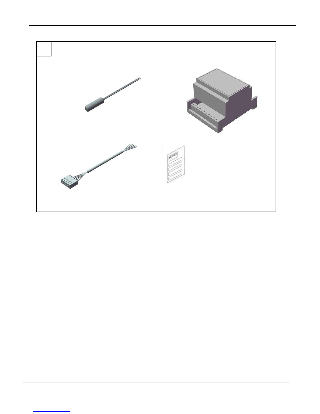
1 Thermistor x 3
2 ACH1 box
3 5 wire adapter
4 Installation manual
1
Page 3
5
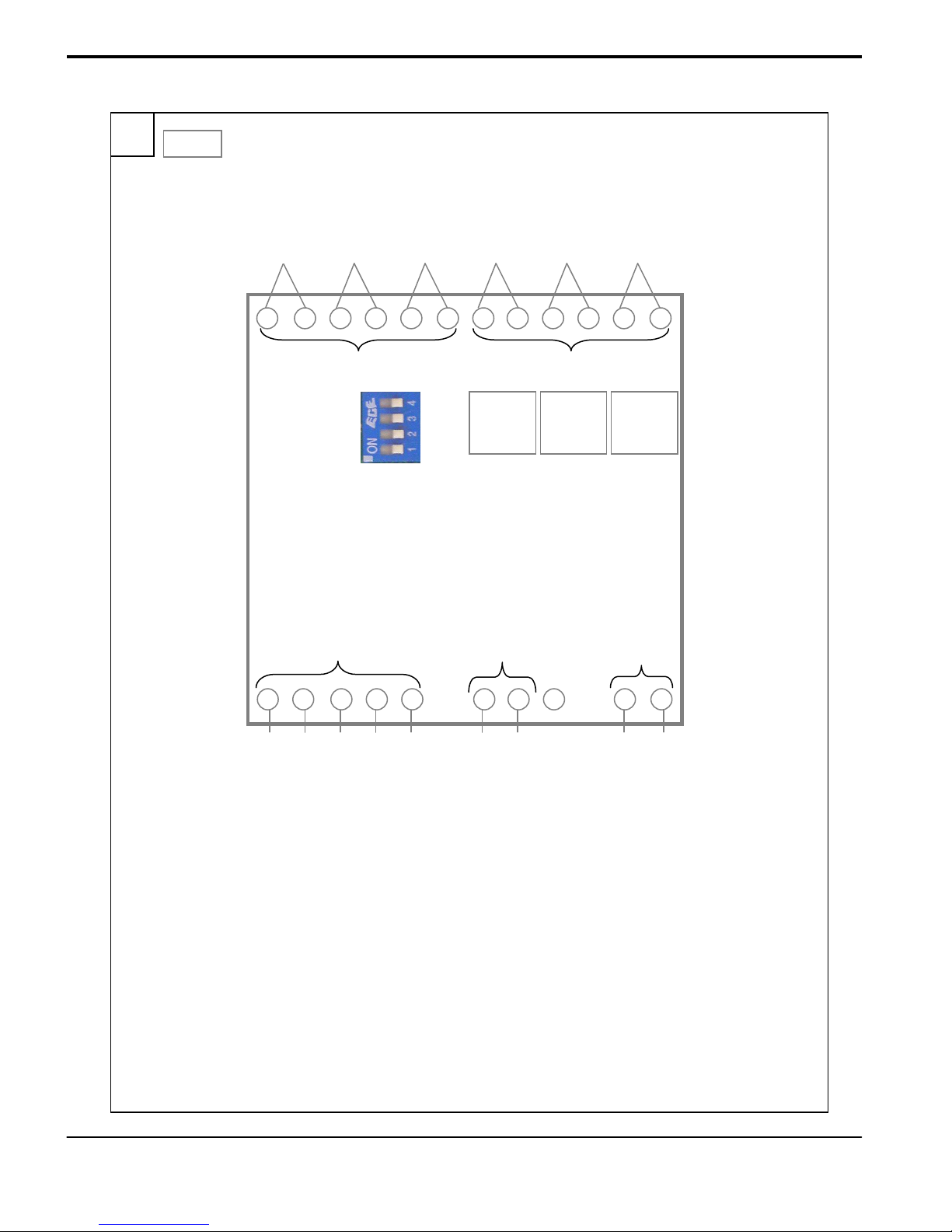
1 2 3 4 5 6 7 8 9 10 11 12
13 14 15 16 17 18 19 20 21 22
T1 (DHW)
T2 (UFH) T3 (UFC) DHW SELECT UFH SELECT UFC SELECT
+ 40°C**
+ 30°C
+ 10°C***
[Fig. 5.1]
A B
Switch ‘ON’
represents
Set Switches
using BCD
encoding*
‘8’
‘4’
‘2’
‘1’
DHW
SET
41-55
Set value =
BCD
setting
UFH
SET
30-45
Set value =
BCD
setting
UFC
SET
10-20
Set value =
BCD
setting
C
1
5
0v +
CN52
* See table 2.1 for more detailed explanation of BCD encoding
** All DHW switches OFF gives 45°C with Immersion Heater Signal
*** UFC settings above 20 are treated as 20
D
E
TH1H
IH Drive
5v 10mA
A Thermistors (5K NTC, R = 5K Beta = 3980 : at 25°C
B Mode select (require volt free inputs)
C 5 wire connector to CN52 on PQFY (1 = black)
D Immersion heater output
E Connection to TH1H on PQFY
2
Page 4
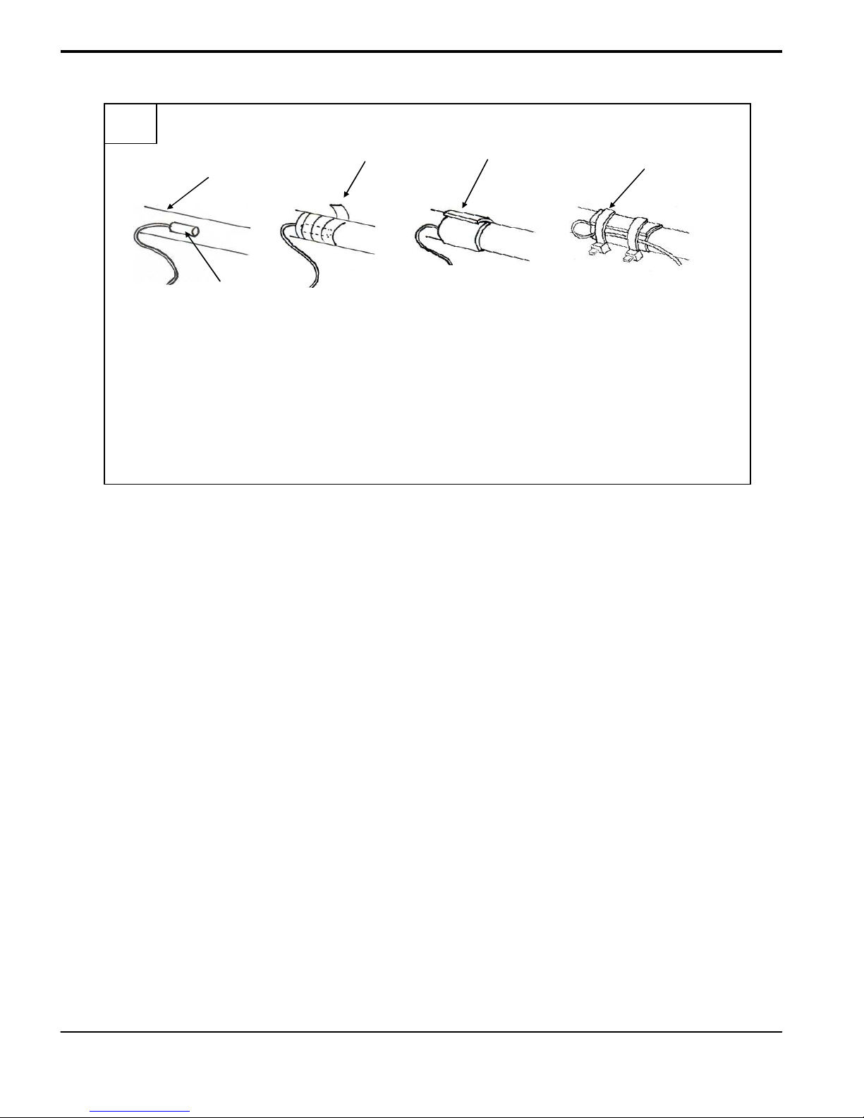
5
[Fig. 5.1.1]
C
A
D
E
B
A Water pipe
B Thermistor
C Aluminium tape (field supply)
D Insulation
E Tie band
3
Page 5
5
5
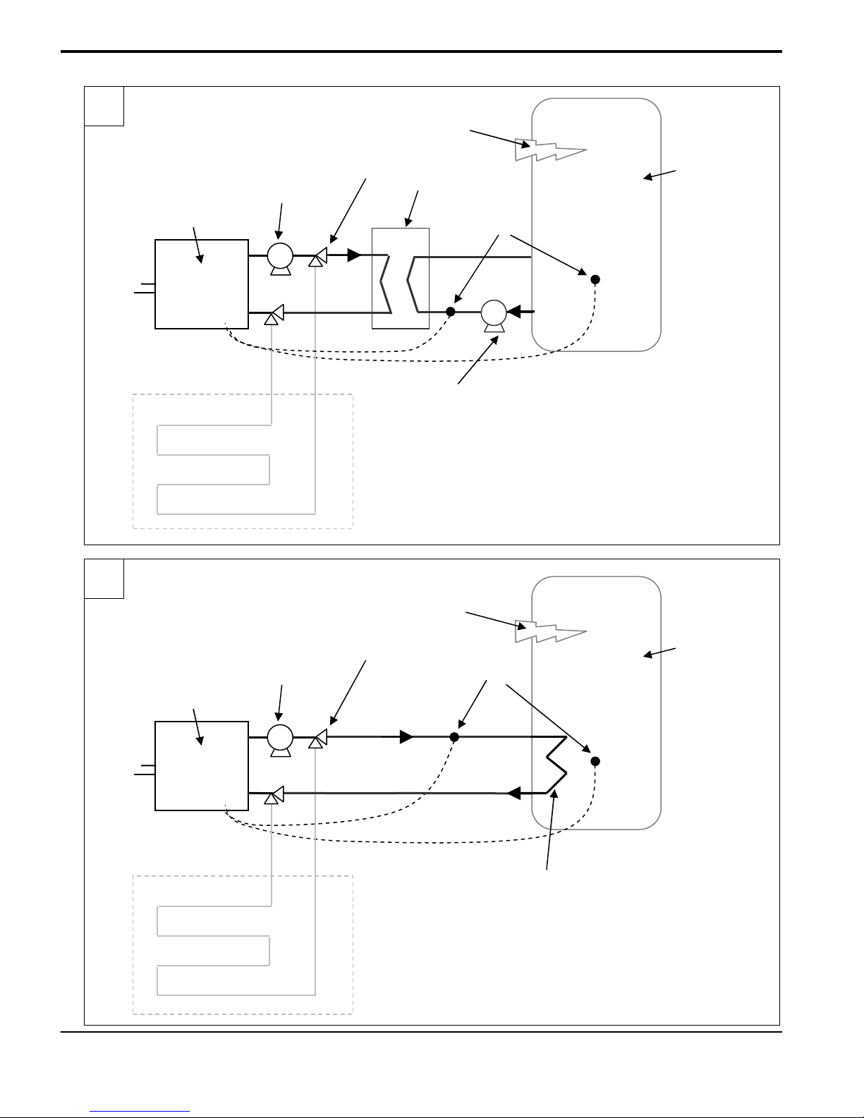
[Fig. 5.1.2.1]
A
B
C
D
E
(b)
B
T1
F
(a)
A PQFY water heater
B Centrifugal pump
C 3 way valve*
D Plate heat exchanger
E Immersion heater
F Water tank (Direct Cylinder)
DHW thermistor [(a) or (b)]
T1
*Only needed if using under floor system
[Fig. 5.1.2.2]
A
B
C
E
(b)
T1
D
F
(a)
A PQFY water heater
B Centrifugal pump
C 3 way valve
D Internal cylinder heat
exchanger (coil)
E Immersion heater
F Water tank (Indirect Cylinder)
DHW thermistor [(a) or (b)]
T1
*Only needed if using under floor system
4
Page 6

5
5
[Fig. 5.1.3]
C
B
A
T2
A PQFY water heater
B Centrifugal pump
C 3 way valve*
D Under floor heating/cooling
D
pipe work
T2 UFH thermistor
[Fig. 5.1.4]
A
B
T3
D
C
*Only needed if using with domestic hot water
A PQFY water heater
B Centrifugal pump
C 3 way valve*
D Under floor heating/cooling
pipe work
T3 UFC thermistor
*Only needed if using with domestic hot water
5
Page 7

5
[Fig. 5.2]
D
A
C
B
G
H
DHW
SET
UFH
SET
UFC
E
SET
F
K
I
J
A Thermistor
B Water pipe/cylinder (see fig 5.3… to see where to attach to)
C Thermistors
D Volt free contacts
E Dip switches (temperature set)
F ACH1 box
G Water pipe/cylinder (see B)
H 5 wire adapter (plug attaches to CN52 on PQFY)
I TH1H connection (attach to ‘inlet air’ TH1H on PQFY)
J PQFY water heater unit
K Immersion heater
L W ater tank
L
6
Page 8

6
1 = ON
0 = OFF
*Note: DHW [0000] (all OFF) causes heat pump boiler to heat to 45°C, followed by signal for immersion heater to 60°C
[Fig. 6.1]
Binary DHW temperature
(°C)
0000 45* 30 10
0001 41 31 11
0010 42 32 12
0011 43 33 13
0100 44 34 14
0101 45 35 15
0110 46 36 16
0111 47 37 17
1000 48 38 18
1001 49 39 19
1010 50 40 20
1011 51 41 20
1100 52 42 20
1101 53 43 20
1110 54 44 20
1111 55 45 20
UFH temperature
(°C)
UFC temperature
(°C)
7
Page 9

Contents
1. Safety precautions.............................................................................................................................................................................8
1.1. Before installation and electric work.................................................................................................................................................8
1.3. Before installation ...........................................................................................................................................................................9
2. Accessories............................................................................................................................................................................................9
3. System components........................................................................................................................................................................10
4. Selecting an installation site ............................................................................................................................................................10
5. Electrical wiring ...............................................................................................................................................................................10
5.1. Connecting the thermistor cables....................................................................................................................................................10
5.1.2 Connecting the Domestic Hot Water (DHW) thermistor T1......................................................................................................11
5.3.3 Connecting the Under Floor Heating (UFH) thermistor T2.......................................................................................................11
5.3.4 Connecting the Under Floor Cooling (UFC) thermistor T3.......................................................................................................11
5.2. Connecting to the PQFY unit.........................................................................................................................................................12
5.3. Connecting the Immersion Signal..................................................................................................................................................12
5.4. Connecting the Mode Select .........................................................................................................................................................12
6. Setting up the Unit and Unit Logic ........................................................................................................................................................13
7. Initial setting and test run......................................................................................................................................................................14
1. Safety precautions
1.1. Before installation and electric work
Before installing the unit, make sure you read all the “Safety
precautions”.
The “Safety precautions” provide very important points regarding
safety. Make sure you follow them.
Symbols used in the text
Warning:
De scr ibe s p rec au t ion s t hat sh oul d b e o b se r ve d t o p r eve nt da n ge r of in jur y o r de a t h t o the u ser .
Caution:
De s cr i b es pre c aut i ons tha t s h o ul d be o bs e r ve d to prevent d a mag e to the uni t.
Warning:
Carefully read the labels affixed to the main unit.
Warning:
• As k t h e d e ale r or an authorised technician to install the controller.
- Improper installation by the user may result in water leakage, electric shock, or fire.
• Us e t he spe ci f ie d cables fo r wi rin g. Mak e t he con nec tio ns sec urel y s o tha t t he o ut s id e f o rce of t h e c ab le i s n ot ap pli e d to th e
terminals.
- Inadequate connecti on and faste ning may generat e heat and c ause a fire.
• Never repair the unit. If the controller must be repaired, consult the dealer.
- If the unit is repaired improperl y, elect ric shock, o r fire may result .
• Inst al l t he co nt r ol le r a cc ord in g t o thi s Ins ta ll a ti on Ma nua l.
- If the unit is installed improperly, electric shock, or fire may result.
• Ha ve all e l ec t ri c w o rk don e b y a li cen sed el ect ric ian ac cor din g t o " E lec tri c F ac i li t y E ng ine e rin g S tan da r d" and " I nte rio r W ire
Re gul at i ons " a nd the i n str uct ion s g i ve n i n t his ma n ua l a n d alw a ys us e a sp eci al cir cui t .
- If the power source capacity is inadequate or electric work is performed improperly, electric shock or fire may res ult.
• Ke ep t h e elect ric p ar ts aw a y fr om wa t er ( w as hi n g water etc. ).
- It might result in electric s hock, fire or smoke.
• When moving and reinstalling the ACH1 unit, consult the dealer or an a uth or is e d tec hn ici an .
- If the controller is installed improperly, elect ric shock, or fire may result.
• To di s pos e o f th i s p r odu c t, c ons u lt you r dealer.
8
Page 10

1.3. Before installation
Caution:
• Do no t i nst al l t h e u ni t wh er e c o mbu sti bl e gas ma y leak.
- If the gas leaks and accumulates around the unit, an explosion may result.
• Do not use the control box where food, pets, plants, precision instrum ents, o r a rtw ork ar e k ept .
• Do no t u se th e co ntr ol box i n sp eci al env ir o nm e nts .
- Oil, steam, sulphuric smoke, etc. can significantly reduce the performance of the air conditioner or damage its pa rts.
1.3.1. Before installation - electrical work
Caution:
• Do not wash the c o ntr o l b ox.
- Washing t hem may caus e an electri c sh ock.
• Be ver y c are ful ab out pr o du ct t ra n sp o rta ti o n.
• Safely dispose of th e p a ck ing ma t er i al s .
- Packing materials, such as nails and other metal or wooden parts, may cause stabs or other inj uries.
- Tear ap art and throw away plastic packaging bags so that childre n will not play with them - If children play with a plastic bag which has not
been torn apa rt, t hey face the risk of suffocation.
1.3.2. Before starting the test run
Caution:
• Do not to u c h t he s wit c hes wi t h we t f i nge r s.
- Touching a switch with wet fingers can cause electric shock.
• Do no t op erat e th e c ont r ol b ox w ith the panels and guards removed.
• Do n ot t u r n off the p ower imm ediat el y a ft er st opp in g o pe rat io n.
- Always wait at least five minutes before tur ning off the power. Otherwise problems may occur.
.
2. Accessories
The unit is provided with the following accessories:
[Fig. 2.1]
No Accessories No supplied
1 Thermistor 3
2 5 wire adapter 1
3 ACH1 1
9
Page 11

3. System components
• ACH1 Control box
• PQFY water heating unit
• Outdoor unit (any type)
• DHW thermistor
• UFH thermistor
• UFC thermistor
• 5 wire adapter
4. Selecting an installation site
• Avoid locations in direct sunlight.
• Avoid locations exposed to stream or oil vapour.
• Avoid locations where combustible gas may leak, settle or be generated.
• Avoid installation near machines emitting high-frequency waves.
• Avoid places where acidic solu tions are frequently handled.
• Avoid places where sulphur-based or other sprays are frequently used.
5. Electrical wiring
Precautions on electrical wiring
Warning:
El ect ric al wor k s hou ld be don e b y q u al i fi ed ele c tr i ca l e ngi nee r s i n a cc ord a nc e w i th "En gin eer ing
St and ar d s f or Ele ctr ica l I nst all at i on" an d s upp li e d i ns t all ati on man ual s. Spe cia l c irc uit s s hou ld a ls o b e
us ed . I f t h e p ow e r c irc uit l a ck s ca pa c it y or ha s a n i ns t al l ati on fai lur e, it m ay ca use a ris k o f e lec t r ic
sh o c k o r f ire.
• Install the unit to prevent any of the control ci rcui t cabl es (remote contr oller, transm ission cables) from direct c ontact with the power cable
outside the unit.
• Ensure that there i s no sla ck on all wi re connections.
• Some cables (p ower, remote co ntroll er, transmission cables) above the ceiling may be prone to be bitten by mice. Insert the cables into
metal pip es for protection.
• Never connect the power cable to leads for the transmission cables. Otherwise the cables could be broken.
Types of control cables
Wiring transmission cables
• Types of transmission cables
Design wiring in accordance with the following table
• Cable diamete r
More than 1.2 5 mm2
5.1. Connecting the thermistor cables
The ACH1 control box is required for the Heat Pump Boiler (PQFY) to switch between domestic hot water and under floor piping heating and
cooling modes. The extra interface, i.e., the ACH1 control box is necessary because when operating in heating, a different temperature must be
monitored often from a different position than when the s ystem is operating in cooling. Thermistor cables (T1, T2, and T3) are attached to ‘A’
terminals [See figure 5.1]. Thermistors are attached to pipe/cylinder [see figure 5.1.1]. For further details on setting up the unit and the unit logic,
see section 6.
Caution:
Do not route the thermistor cables together with power cables.
Caution:
When the lead wire is too long, cut it to the appropriate length. Do not bind it in the box.
Caution:
Take proper measures not to miswire.
10
Page 12

5.1.2 Connecting the Domestic Hot Water (DHW) thermistor T1
Direct cylinder with plate heat exchanger
[Fig 5.1.2.1]
The thermistor can be attached to different parts of the system depending on the set up and the availability of connection points.
Note1: Thermistor (T1) attached to terminals 1 & 2 on ACH1 unit [Fig 5.1].
Note2: If the water heated from the HPB at 45°C is in a separate tank to the immersion heater taking the water temperature up to 60°C, the 45°C
water must be kept circulating to maintain legionella control.
• Type (a) – T1 attached to cylinder
• Type (b) - T1 attached to inlet to the plate heat exchanger (cylinder water outlet)
Indirect Cylinder
[Fig 5.1.2.2]
The thermistor can be attached to different parts of the system depending on the set up and the availability of connection points.
Note: Thermistor (T1) attached to terminals 1 & 2 on ACH1 unit [Fig 5.1].
• Type (a) – T1 attached to cylinder
• Type (b) - T1 attached to inlet to cylinder pipe (PQFY water outlet)
o Set temperature to no more than 45°C (0101).
o Immersion function available – set temperature to 45°C (0000 – all OFF).
o When 44°C is achieved on T1, the immersion signal comes on and heats to 60°C. For more information see Unit Logic [section 6]*.
o Set temperature to no more than 45°C (0101).
o No immersion heater function available.
o Set temperature to no more than 45°C (0101).
o Immersion function available – set temperature to 45°C (0000 – all OFF).
o *See as above.
o Set temperature to 53°C (1101) on ACH1.
o ONLY USE WHEN TANK SURFACE IS INACCESSABLE.
o No immersion heater function available.
In order to increase the output temperature of the water it is necessary to increase the condensing temperature of the
Heat Pump. This is achieved by setting a Dip Switch as follows.
• PUMY-P100/125/140YMH, PUMY-P100/125/140VMH, SW 6-6 to the ON position.
• All City Multi P200 and above, SW3-7 to the ON position.
5.3.3 Connecting the Under Floor Heating (UFH) thermistor T2
[Fig 5.1.3]
Note: thermistor (T2) attached to terminals 3 and 4 on ACH1 unit [Fig 5.1].
• T2 attached to water inlet to PQFY (return from under floor system)
o Set temperature to desired return temperature from under floor system.
o i.e. 35°C (0101) return temperature would typically mean an outlet temperature to under floor system of 45°C, giving at temperature
difference of 10°C.
5.3.4 Connecting the Under Floor Cooling (UFC) thermistor T3
[Fig 5.1.4]
Note: thermistor (T3) attached to terminals 5 and 6 on ACH1 unit [Fig 5.1].
• T3 attached to water outlet from PQFY (outlet to under floor s ystem)
o Set temperature to desired outlet temperature from under floor system, typically minimum allowable to avoid condensation on the
floor surface.
o i.e. no less than 18°C (1000) for laminate flooring.
11
Page 13

5.2. Connecting to the PQFY unit
5.2.1. Five Wire Adapter
[Fig 5.1 [C] and 5.2]
Attach the 5 wires on the adapter to ACH1 (CN52) starting with black to terminal 13, followed by red (14), white (15), yellow (16) and green (17). Insert plug
end to CN52 on the PQFY water heating unit PCB. Please note power to the ACH1 box is provided through the 5 wire adapter.
No te :
Ensure that the w iri n g is no t pi n c he d wh e n f i tti n g t he t erm i n al box cov er. P in c hin g the wi r ing may cu t it .
Caution:
Install wiring so that it is not tight and under tension. Wiring under tension may br eak , o r o ver hea t a n d bur n.
• After wiring is complete, make sure again that the re i s no slack on the co nnections, a nd attach the cov er onto the control box in the reverse or der
removal.
5.2.1. TH1H
[Fig. 5.2 [E] & 5.3]
Attach 2 core Non-polarised 1.25mm shielded wire to both terminals 21 and 22, and then feed back to PQFY TH1H terminals ‘inlet air’ on PCB (see PQFY
manual).
No te :
Ensure that the w iri n g is no t pi n c he d wh e n f i tti n g t he t erm i n al box cov er. P in c hin g the wi r ing may cu t it .
Caution:
Install wiring so that it is not tight and under tension. Wiring under tension may br eak , o r o ver hea t a n d bur n.
• After wiring is complete, make sure again that the re i s no slack on the co nnections, a nd attach the cov er onto the control box in the reverse or der
removal.
5.3. Connecting the Immersion Signal
If immersion heating is required (check set up [Section 5.1.2]), then a connection has to be made between the ACH1 unit and the immersion
heater. When water has reached 44°C, the IH drive will become energised, and send a signal to the immersion heater to start.
Attach 2 core 1.25mm shielded wire to both terminals 18 and 19 on the ACH1 [Fig 5.1 [D]] and then to immersion heater, noting polarity.
No te :
Ensure that the w iri n g is no t pi n c he d wh e n f i tti n g t he t erm i n al box cov er. P in c hin g the wi r ing may cu t it .
Caution:
Install wiring so that it is not tight and under tension. Wiring under tension may br eak , o r o ver hea t a n d bur n.
• After wiring is complete, make sure again that the re i s no slack on the co nnections, a nd attach the cov er onto the control box in the reverse or der
removal.
5.4. Connecting the Mode Select
Attach 2 core 1.25mm shielded wire on the following terminal blocks on ACH1 [Fig 5.1 [B]].
When a volt free connection is made, the mode will become selected and the unit will operate accordingly.
No te :
Ensure that the w iri n g is no t pi n c he d wh e n f i tti n g t he t erm i n al box cov er. P in c hin g the wi r ing may cu t it .
Caution:
Install wiring so that it is not tight and under tension. Wiring under tension may br eak , o r o ver hea t a n d bur n.
• After wiring is complete, make sure again that the re i s no slack on the co nnections, a nd attach the cov er onto the control box in the reverse or der
removal.
Notes:
• Ch e c k t h a t th e bun c h of w ires d o n o t co m e off ev en if they are pulled strongly.
o For DHW select, connect wires between terminals 7 and 8.
o For UFH select, connect wires between terminals 9 and 10.
o For UFC select, connect wires between terminals 11 and 12.
12
Page 14

6. Setting up the Unit and Unit Logic
The ACH1 box can be used for different solutions. The unit can run all modes (DHW, UFH and UFC) on one PQFY system, but follows logic to
enable the best performance possible from the system. There can be any combination of modes. The next section details different scenarios and
explains how the unit responds.
Note: a PAR21 controller is needed along side the ACH1 and set to Auto mode
28°C. To see how this applies and is implemented please see the PQFY
manual.
6.1. DHW no Immersion Heater (IH)
Used when standalone immersion control is available.
• Volt free connection is made between terminals 7 and 8 [Fig 5.3]
• Unit will sense temperature from T1 thermistor (connected on terminals 1 and 2)
• Desired temperature can be set on dipswitch (DHW) whereby ON = 1, OFF = 0 (see table 6.1 for binary coding and corresponding temperatures in each
mode)
• Unit will switch off when T1 senses the set temperature.
• Thermistors work to a diversity of ±1°C.
6.2. DHW with Immersion Heater
Immersion can only be used when T1 is attached to the tank as in [5.3.2. type (a)] and when the immersion is submerged in the same tank as the
water heated from the PQFY.
• Volt free connection is made between terminals 7 and 8 [Fig 5.3]
• Unit will sense from T1 thermistor (connected terminals 1 and 2)
• Temperature set to 45°C (0000) all OFF on DHW dipswitch.
• When T1 reaches 44°C, a signal will be sent to the IH to come on and stay on until 60°C is sensed on T1 even if the DHW signal is lost on terminals 7
and 8.
• If T1 drops below 45°C, the PQFY will come on and the immersion will switch off. IH will then come on again at 44°C until T1 has achieved 60°C.
• If DHW signal is lost and T1 is below 45°C and 60°C hasn’t been achieved within one DHW cycle (i.e. signal is not renewed), immersion will come on and
heat the water to 60°C.
• Once 60°C is reached on T1 (legionella is controlled) in any case within one cycle (signal is not renewed), the immersion will not come on again. The
immersion will only be re-started if the DHW signal is lost, then renewed.
6.3. UFH
Used when under floor heating only is required.
• Volt free connection is made between terminals 9 and 10 [Fig 5.3]
• Unit will sense from T2 thermistor (connected terminals 3 and 4)
• Desired temperature can be set on dipswitch (DHW) whereby ON = 1, OFF = 0 (see table 2.1 for binary coding and corresponding temperatures in each
mode)
• Unit will switch off when T2 senses the set temperature.
6.4. UFC
Used when under floor cooling only is required.
• Volt free connection is made between terminals 11 and 12 [Fig 5.3]
• Unit will sense from T3 thermistor (connected terminals 5 and 6)
• Desired temperature can be set on dipswitch (DHW) whereby ON = 1, OFF = 0 (see table 2.1 for binary coding and corresponding temperatures in each
mode)
• Unit will switch off when T3 senses the set temperature.
o Unit can be set from 41°C (0001) up to 55°C (1111)
o Unit can be set from 30°C (0000) up to 45°C (1111)
o Unit can be set from 10°C (0000) up to 20°C (1011). Note anything above 1011 will equal a set temperature of 20°C.
13
Page 15

6.5. DHW and UFH
In this case the DHW takes priority over the under floor heating. It is more important to have DHW than space heating, so until the water is up to
temperature (45°C), the system will control to the DHW set point. This may mean that water slightly hotter than 45°C being applied to the under
floor heating system for a period of time.
• The system will operate as in 6.2, with the system being controlled from T1 until the set point has been achieved.
• After which point the UFH signal (T2) will take control as in 6.3.
• If using DHW with IH signal output; once DHW is heated to 45°C, IH will come on and stay on until 60°C at the same time UFH signal (T2) will take over.
6.6. DHW and UFC
The same priority takes place with DHW and UFC, DHW is more important than UFC.
• The system will operate as in 6.2, with the system being controlled from T1 until the set point has been achieved.
• After which point the UFC signal (T3) will take control as in 6.4.
• If using DHW with IH signal output; once DHW is heated to 45°C, IH will come on and stay on until 60°C at the same time UFC signal (T3) will take over.
6.7. UFH and UFC
Both w ill w ork w hen i nde pende ntly requi red. If both modes ar e req ueste d sim ult aneousl y t her e will be NO operation.
7. Initial setting and test run
See P QFY manual for commissioning and testing.
14
Page 16

This product is designed and intended for use in the residential, commercial
and light-industrial environment.
The product at hand is based on the following EU regulations:
• Low Voltage Directive 73/23/EEC
• Electromagnetic Compatibility Directive 89/336/EEC
Please be sure to put the contact address/telephone number on
this manual before handing it to the customer.
MITSUBISHI ELECTRIC UK
MITSUBISHI ELECTRIC UK, TRAVELLERS LANE, HATFIELD, HERTDFORSHIRE, AL10 8XB
15
 Loading...