

Page 1
il
v
0
n
MtTSUBrSfril
MOTORS
Worlrshop
Mqnuql
chossis
SUPPLEMENT
,,v
L
SOOOGiT'gg
ffi
-:
---
:----:E--+=::-
###
Page 2

IvIITSUBISHI
General
Fuel
.
@
Iil
'!,
3Ct00GT
WORKSHOP
SUPPLEMENT
FOREWORD
Workshop
This
moval, disassembly,
sembly
Use the
combination
All information,
tions
time
to
obligation.
and
manuals
conlained
publication.
of
make changes
Manual
installation,
with this
illustrations
in
contains
inspection,
indicated
manual
manual
this
We,
at any
MANUAL
procedures
adjustment,
service
for
etc.
on the
however,
time
following
required.
as
product
and
are current
reserve
without
prior
mechanics.
page
descrip-
as at
the
notice or
for
reas-
the
right
re-
in
Engine
Heater,
Ventilation
and
Electrical
Air conditioner
IT
E
@
Mitsubishi
J.
t t lroroRs
Motors corporation
MITSUBISHI
coRFoRATrol{
(.,
Page 3
RELATED
PUBLICATIONS
TECHNICAL
WORKSHOP
Chassis
Engine
ELECTRICAL
PARTS
INFORMATION
<Europe>
<General
Australia>
<Europe>
<General
Australia>
<Europe>
<General
<Australia>
MANUAL
Group
Export,
Group
WIRING
Export,
CATALOGUE
Export,
MANUAL
GCC and
GCC
and
GCC>
PYUE92O1
PWUE9119
PWUE9119-E
PWUE9119-F
PWUE9119
PWUE92O3
PWUE9203-1
PWUE92O3-2
PWUE92O3.3
PWUE92O3-4
PWEEIf,
PHUE9201
PHU
E920
PHUE9201
PHUE9201
PHUE9406
PHUE9406-1
PH
UE9406-2 (Supplement)
8608K4O8Atr
8808K408An
BFASK4OSAN
(Loose-leaf
Supplement)
Supplement)
Loose-leaf
Basic)
Supplement)
Supplement)
Supplement)
Supplement)
nn (Loose-leaf
(Loose-leaf
-D
(Supplement)
1
-E
(Supplement)
-F
(Supplement)
(Basic)
(Supplement)
edition)
edition)
edition)
edition)
WARNINGS
(sRS)
WARNING!
(1)
lmproper
can.lead
bag)
(2)
at it
.-. 9r
(3)
Service
only
(4)
MITSUBISHI
5?B
of any
EQUTPPED
or to
possible
is
in.drying
or
at an
-
Supplemental
component
REGARDING
service
personal
to
the driver (from
after
maintenance_of
authorized
dealer
VEHTCLES
or maintenance
iniury
that
the SRS
painting,_remove
MITSUBISHI
personnel
Restraint
of
the SRS
or death
rendering
components
SRs
-qny
must
System
or
OF
SUPPLEMENTAL
of any
the
component
to se_rvice
the
SRS inoperative).-
are
SRS compon6nts
componeni
dealer.
thoroughly
(SRS),
any SRS-related
personnel
subjected
or SRS-relateJ
review
before
of the
(air
this manual,
beginning
component.-
RESTRAINT
SRS,
or any
(from
to heat
bag
module,
component
SRS-related
inidvertent
over
93"C
SRS-LCU)
and
especially
any
service
SYSTEM
component,
firing
(200.F)
must
be
or maintenance
'the
of
in
beforehandl
performed
its
GROUP
air
baking
Page 4
v
GENERAL
GENERAL OO
-
Vehicle ldentification
00-1
GENERAL
I
VEHICLE IDENTIFICATION
J
MODEL
VEHICLES FOR EUROPE
Model code Engine
Zl6AMJGFL6 6G72
Zl6AMJGFR6
VEHICLES FOR GENERAL
EXPORT
model
(2,972
m(
Transmission
)
W6MG1
model Fuel
MPI
supply system
v
Model code Engine
Zl6AMNGFL
Zl6AMNGFR
VEHICLES FOR GCC
Model code
6G72
Engine model
model
(2,972
m(
)
Transmission model Fuel supply system
WsMG1
Transmission model Fuel
MPI
supply system
Zl6AMNGFLW
VEHICLES
Modelcode
Zl6AMNGFRs
6G72
FOR AUSTRALIA
Engine
6G72
(2,972
model
(2,972
m(
)
m(
)
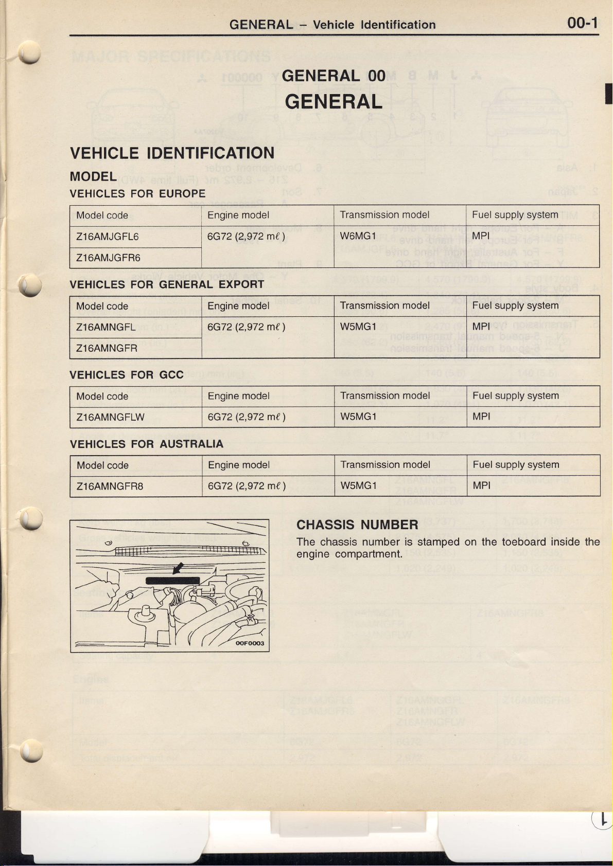
CHASSIS
The chassis number is stamped on the toeboard inside the
engine compartment.
WsMG1 MPI
Transmission model Fuel supply system
WsMG1 MPI
NUMBER
Page 5
00-2
GENERAL
-
Vehicle ldentification
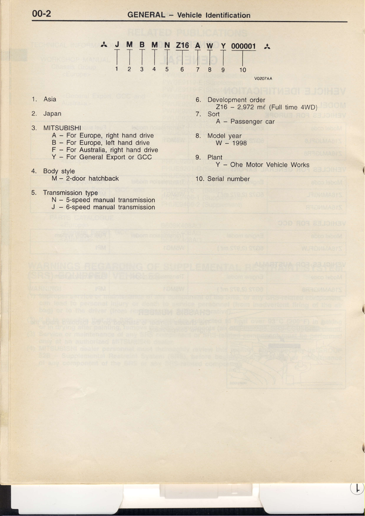
1. Asia
2.
Japan
MITSUBISHI
3.
4.
5.
-
A
-
B
F - For
Y - For
Body style
M - 2-door
Transmission
-
N
-
J
AJMBMN216AWY
TTTTT_I-TTT
ttttttltl
123456789
For Europe, right hand
For
Europe, left hand drive
Australia, right hand
General Export
hatchback
type
S-speed manual
6-speed manual
or GCC
transmission
transmission
drive
drive
000001
--r-
I
10
6. Development
216 - 2,972
7.
Sort
-
A
Passenger
Model
L
9. Plant
10.
Serial number
year
w - 1998
-
Y
Ohe Motor Vehicle
order
A
VO2OTAA
(Full
md
car
time 4WD)
Works
Page 6
GENERAL - Major
Specification
00-3
ty
v
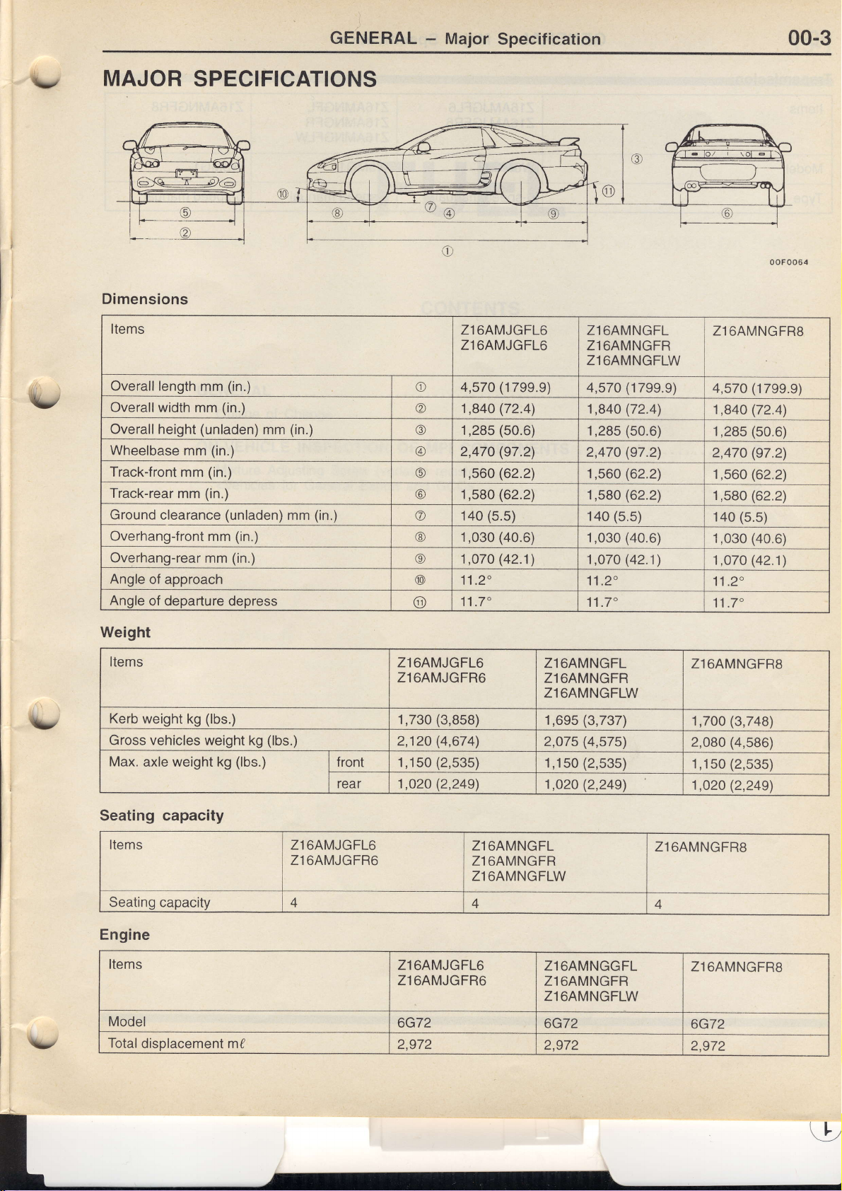
MAJOR
SPECIFICATIONS
Dimensions
Items
Overalllength
Overallwidth
Overallheight
Wheelbase
Track-front
Track-rear
Ground
Overhang-front
Overhang-rear
Angle
of approach
Angle
of
mm
mm
mm
mm
clearance
departure depress (,
(in.)
mm
(in.)
(unladen)
(in.)
(in.)
(in.)
mm
mm
mm
(unladen)
(in.)
(in.)
(in.)
mm
(in.)
Zl6AMJGFL6
Zl6AMJGFL6
o 4,570
@ 1,84O
@ 1,285
@ 2,470
@ 1,560
@ 1,580
O 140
@ 1,030
o 1,O7O
@ 11 .2"
(1799.9)
(72.4)
(50.6)
(97.2)
(62.2)
(62.2)
(5.s)
(40.6)
(42.1)
1'1 .7'
Zl6AMNGFL
Zl6AMNGFR
Zl64MNGFLW
(',t799.9)
4,570
(72.41
1,84O
(50.6)
1,28s
(97.21
2,470
(62.2)
1,560
(62.2)
1,580
(5.5)
140
(40.6)
1,030
(42.1)
1,070
'l.1
.2"
11 .7"
oo
Foo64
Z1
6AMNGFRs
(17e9.9)
4,570
(72.4)
1,840
(50.6)
1,285
(97.2)
2,470
(62.2)
1,560
(62.2)
1,580
(5.s)
140
(40.6)
1,030
(42.1)
1,07O
11 .2"
11 .7"
\/
v
Weight
Items
Kerb
weight kg
Gross vehicles weight
Max.
axle weight kg
(lbs.)
Seating capacaty
Items
Seating
Engine
Items
Model
Total
capacity 4
disolacement mf
kg
(lbs.)
(lbs.)
Zl6AMJGFL6
Zl6AMJGFR6
Zl6AMJGFL6
Zl6AMJGFR6
't,730
2,120
front
rear 1,O20
1,150
Zl6AMJGFL6
Zl6AMJGFR6
6G72
2,972
(3,858)
(4,674',)
(2,53s)
(2,249)
Zl6AMNGFL
Zl64MNGFR
Zl64MNGFLW
A
Zl6AMNGFL
Zl6AMNGFR
Zl6AMNGFLW
(3,737)
1,6e5
(4,s751
2,075
(2,535)
1,150
(2,249)
1,020
Zl6AMNGGFL
Zl6AMNGFR
Zl6AMNGFLW
6G72
2,972
Zl6AMNGFRs
(3,748)
1,700
(4,s86)
2,080
(2,535)
r
,150
(2,249)
1,020
Zl6AMNGFRs
4
Zl6AMNGFRS
6G72
2,972
Page 7
00-4
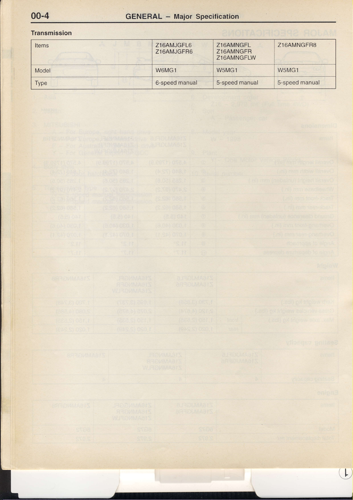
Transmission
GENERAL
-
Major
Specification
Items
Model
Type
Zl6AMJGFL6
Zl6AMJGFR6
W6MGl WsMG1
6-speed
manual 5-soeed manual 5-speed
Zl6AMNGFL
Zl6AMNGFR
Zl6AMNGFLW
Zl64MNGFRs
W5MG1
manual
[,
Page 8
v
13-1
FUEL
CONTENTS
GENERAL
Outline
ON.VEHICLE INSPECTION
Mixture
<Vehicles
of Change
Adjusting
for
Screw
General Export
OF MPI
(variable
COMPONENTS
resistor)
and GCC> .
.......
..
2
.. 2
2
Page 9
13-2 FUEL
GENERAL
CHANGE
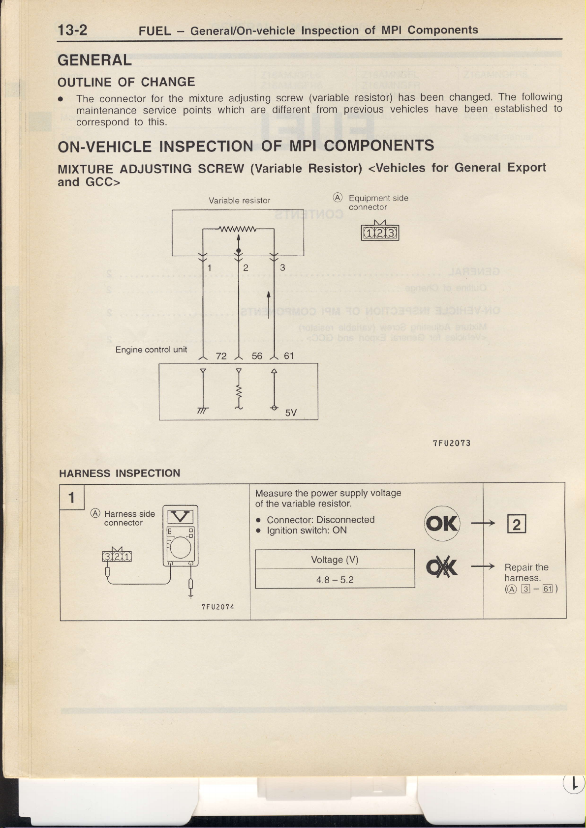
OUTLINE
.
The connector
maintenance
correspond
ON-VEHICLE
OF
for the
service
to this.
INSPECTION
-
General/On-vehicle
mixture
points
adjusting screw
which are different
OF
MPI
Inspection
(variable resistor) has been
from
of
prevtous
Components
vehicles
have been
MPI COMPONENTS
changed.
established
The
following
to
MIXTURE
and Gcc>
ADJUSTING
Engine control
SCREW
Variable
resrstor
TTI
t*l
+
L
(Variable
Resistor)
tuu
<Vehicles
Equipment side
@
connector
ltir2ml
for
General
?FU2O?3
Export
HARNESS
INSPECTION
Measure the
of the variable
o
Connector:
o
lgnition switch:
power
Disconnected
Voltage
4.8 - 5.2
supply
resistor.
ON
(V)
voltage
@
OK
Repair
harness.
the
@tr-m)
o
Page 10
FUEL
-
General/On-vehicle
Inspection
of
MPI
Components
13-3
[sz-l
L-f-_J
t-o]
I
t"\-
?FU2O?5
Engine control
harness
unrt
side connector
?FU2O?6
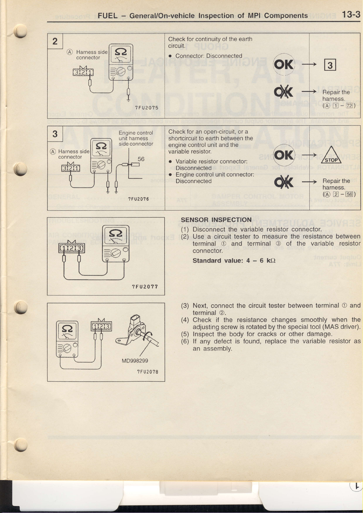
Check
circuit.
o
Check for an open-circuit,
shortcircuit
engine control unit
variable resistor.
for continuity of the earth
Connector:
o
Variable resistor connector:
Disconnected
o
Engine control
Disconnected
Disconnected
to earth between the
and
the
unit connector:
or a
Repair
narness.
the
@tr-E)
Repair the
harness.
-@)
(@
tr
t-CI-t
LJRJ
7 F U2077
fr
|vl
p.b.
W@L
@--f ,/
-:Jr
MD998299
r'a\
,/ \r
?FU2O?8
SENSOR
(1)
Disconnect
(2)
Use
terminal O and terminal
connector.
Standardvalue:4-6kO
(3)
Next, connect the circuit tester between
terminal @.
(4)
Check if the
adjusting screw
(5)
lnspect
(6)
lf
an
INSPECTION
variable
the
a circuit tester to
resistance changes smoothly
is rotated by the special tool
the body
defect
any
assembly.
is
resistor
measure the resistance between
@ of the
for cracks or other damage.
found,
replace the
connector.
variable resistor
terminal O and
when the
(MAS
variable resistor as
driveQ.
Page 11
16-1
ENGINE
ELECTRICAL
-
General/Specifications/Service
Adiustment
Procedure
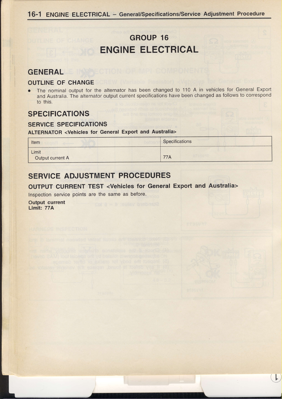
GENERAL
CHANGE
OUTLINE
o
The
and
to this.
OF
nominal output
Australia.
The alternator
for the
SPECIFICATIONS
SERVICE
ALTERNATOR
Item
Limit
Output
SPECIFICATIONS
<Vehicles
current
A
for General
GROUP
ENGINE
allernator
output
current
Export and
ELECTRICAL
has been
specifications
16
changed
have been changed
Australia>
Specifications
774
110 A in
to
vehicles
follows to correspond
as
for General
Export
SERVICE
OUTPUT
Inspection
Output
Limit: 77A
current
ADJUSTMENT
CURRENT
service
points
TEST
the same
are
PROCEDURES
<Vehicles
for General
as before'
Export
Australia>
and
(L)
Page 12
55-1
\/
HEATER,
CONDITIONER
AND
GENERAL
Outline of Changes
TROUBLESHOOTING
AIR
CONDITIONER
PANEL AND ECU ASSEMBLY
CONTROL
VENTILATION
CONTENTS
.........2
. . .. . . .. 2
.....
.......27
DAMPER CONTROL
ASSEMBLY
COMPRESSOR
2
CONDENSER
MOTOR
AIR
MOTOR
.
AND CONDENSER
.......28
...29
FAN
..... 29
\,
Page 13
55-2 HEATER.
AIR CONDITTONER
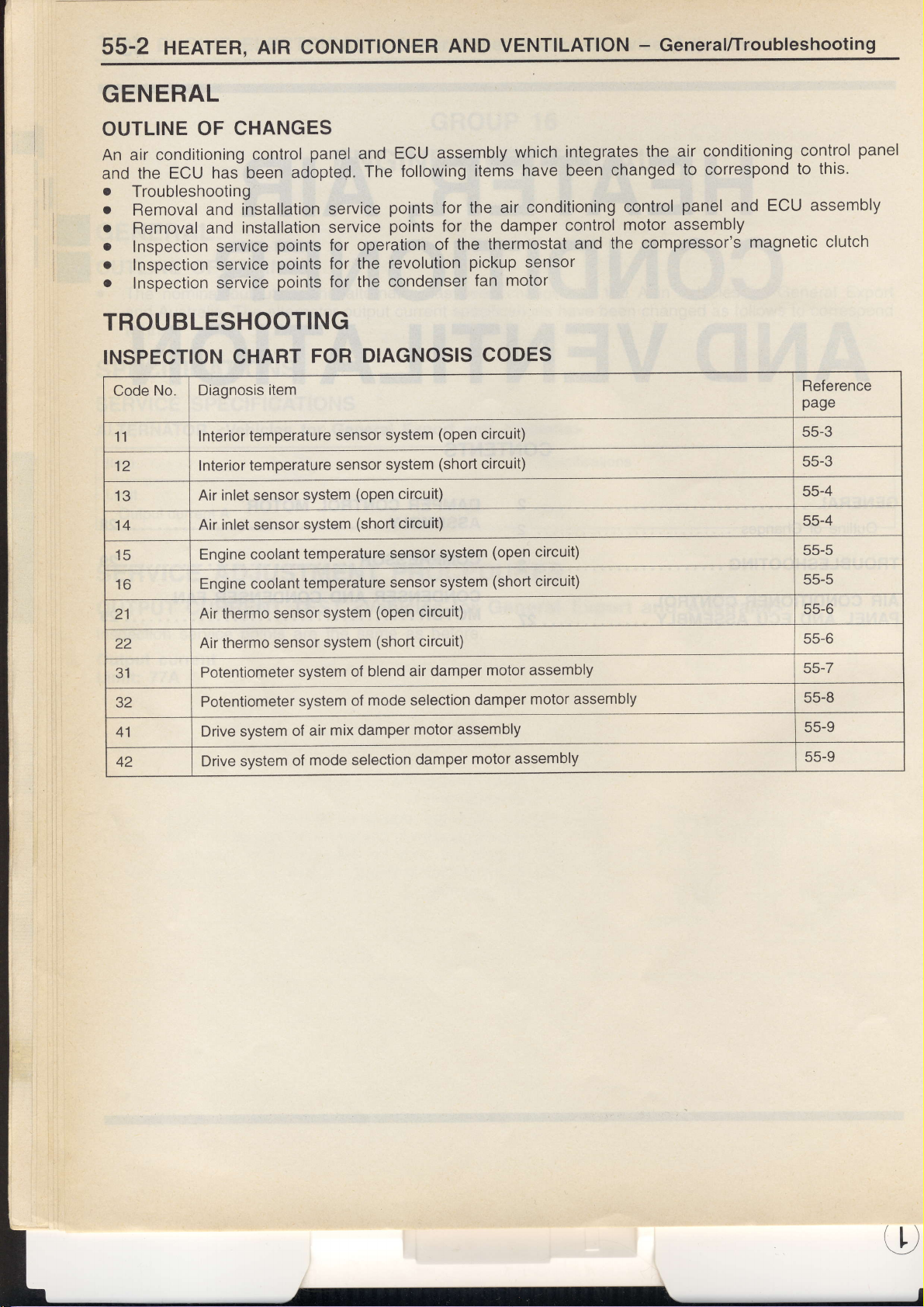
GENERAL
CHANGES
OUTLINE
An air conditioning
the ECU
and
o
Troubleshooting
o
Removal
o
Removal
o
Inspection
o
Inspection
o
Inspection
OF
control
hal been
installation
and
installation
and
service
service
service
panel
adopted.
service
service
points
points
points
for operation
for
for
and
The
the
the condenser
TROUBLESHOOTING
AND
VENTILATION
ECU assembly
following
points
points
revolution
items
the air
for
for the
of
damper
the thermostat
pickup
fan motor
which
integrates the
been
have
conditioning
control
and
sensor
-
General/Troubleshooting
air conditioning
changed
control
to correspond
panel
motor assembly
compressor's
the
ECU
and
magnetic
control
to this.
assembly
clutch
panel
INSPECTION
No. Diagnosis
Code
11
12
13
14
15
16
21
22
31
32
41
42
CHART
lnterior temperature
Interior temperature
inlet sensor
Air
inlet sensor
Air
Engine coolant
Engine
Air thermo
Air thermo
Potentiometer
Potentiometer
Drive system
Drive system
item
coolant
sensor
sensor
system
system
of air
of
FOR
system
system
temperature
temperature
mode selection
DIAGNOSIS
sensor
sensor
system
system
mix damper
system
system
(open
(short
(open
(shott
blend air
ol
mode
of
circuit)
circuit)
sensor
sensor
CODES
(open
circuit)
(short circuit)
system
system
circuit)
circuit)
damper
selection
motor assembly
damper
(open
(short
motor
damper
motor
circuit)
circuit)
assembly
motor assembly
assembly
Reference
page
55-3
55-3
55-4
55-4
55-5
55-5
55-6
55-6
55-7
55-8
55-9
55-9
U
Page 14

HEATER,
INSPECTION PROCEDURES
AIR
CONDITIONER
FOR
AND
VENTILATION - Troubleshooting
DIAGNOSIS CODES
55-3
Code
ff ir
Measure at
o
.
Measure at the A/C-ECU connector
o
.
No.11
Oirg
Disconnect the connecl
harness
Voltage between terminal
OK: 5V
Connect the connector.
Voltage between
OK:
lhe
side connector
2.3 - 2.9V
12 lnterior temperature
or
lor<
V rrn
interior lemperature
the connector, and
(2)
terminal
(15)
and body earth
and
sensor connector
measure at the
C-97
body earth
sensor
F-01
system
Probable cause
i
.
Malfunction of
r
Malfunction ol harness
r
Malfunction of interior lemperalure sensor
.
Malfunction of the
Replace
the harness between the
Check
A/C-ECU.
the
Check the
F-01 , F-32
F-01 , F-32,
following connectors:
C-62
<L.H.
drive
<R.H.
drive vehicles>
connector
A/C-ECU
OK
V
iNG
V
interior
lo^
I
vehicles>
Repair
temperalure
Renair
iNo
I
sensor and
l*o
t-
Check the
the A/C-ECU, and if necessary.
Replace the
I
harness between
A/C-ECU.
the
interior temperature sensor and
I
i
Page 15

55-4 HEATER.
AtR
CONDTTTONER
AND
VENTILATION
-
Troubleshooting
No.13
Code
This diagnosis
is an oDen
there
Measure
.
.
Measure
.
.
at the
Disconnect
side conneclor.
between
Voltage
OK:5V
at the
Connect
Voltage
OK:
the connector.
between
-
2.3
inlet sensor
Air
is output
code
circuit
air lemperature
outside
connector,
the
terminal
A,/C-ECU
terminal
2.9 V
system
is a defective
if
there
harness.
in the
OK
V rrn
sensor
measure at
and
(2)
body
and
(7)
C-97.
and
body earth
connector
(open circuit)
connector
harness
the
earth
connector
C-19.
connection,
++
if
or
Replace
Check the
Check
Check
Probable
.
Malfunction
.
Malfunction
.
Malfunction
o
Malfunction
harness
following connectors:
the
the trouble
cause
of
oI harness
of the air
of the
between
symptom.
connector
inlet sensor
A/C-ECU
OK
l
V
inlet sensor
the air
C-05
and the
A/C-ECU
No.l4
Code
This diagnosis
input circuit.
Measure at
.
Connect
.
Voltage between
OK: 2.3
Reolace the
the
the
-
A/C-ECU
inlet
Air
is
code
A/C-ECU
connector.
terminal
V
2.9
sensor
if there
output
connector
(7)
and
system
is a short
C-97.
body
earth
(short
circuit
circuit)
in the air
inlet sensor
Check the
and
Reolace the
harness
repair
Probable
r
.
.
.
the
Check
repair
and
between
i{ necessary.
A,rC-ECU.
cause
Malfunction
Malfunction
Mal{unction
Malfunction
between the
harness
necessary.
if
the air inlet
harness
of
of connector
of the
of the
inlet sensor
air
A'IC-ECU
air inlet sensor and
sensor
and the
the
A/C-ECU'
A/C-ECU'
('
Page 16

HEATER,
AIR CONDITIONER
AND
VENTILATION
-
Troubleshooting
55-5
Gode
(open
This diagnosis
there
Engine
M""*,*"rrh"";gin".ootffiillG-
.
.
t
Measure at the
o
.
No.15
circuit)
is an open
coolant temperature
Disconnecl
connector
side
Voltage between
5V
OK:
Connect
Voltage
2.3
OK:
Engine
code
circuil
the connector.
terminal
fuC-ECU connector
connector.
the
-
terminal
2.9 V
between
coolant
is output
in the
sensor
(1)
(14)
if there
harness.
check
measure at
and
and body
T;,-
and
temperature
is a defective
the
eanh
-*
C-97.
earth
body
connector
harness
sensor
connection,
]
| -r
system
or il
-[cr*"r,t"
-
Check the trouble
Check
Probable
.
Malfunction
.
Malfunction of
o
Malfunction of
sensor
.
Malfunction
t"lr"*lgl""":1?r'
following connector:
the
cause
of connector
of the
-- -Ioi---
-
symptom.
harness
the engine
A/C-ECU
"-tt
;
C-35
coolant
-----
temperature
-
I
Repair
---
i
r
the following
Check
Code
(short
This diagnosis
lemperature sensor
Reolace the
No.l6
circuit)
code is output
tuC-ECU.
connector:
C-97
Engine coolant
is a short
input circuit.
if there
toK
I
temperature
in the engine
circuit
Reolace the
sensor system
coolant
Check
and the
A/C-ECU.
Probable
.
Malfunction
.
Malfunction
.
Malfunction
sensor
.
Malfunction
the harness
A/C-ECU,
cause
harness
of
connector
of
of the engine
of the
between
and repair
the
coolant
A/C-ECU
water temperature
heater
if necessary.
temperature
sensor
Page 17

5s-6
HEATER,
AIR
CONDITIONER
AND
VENTILATION
-
Troubleshooting
Code
This diagnosis
there
Air thermo
Measure
.
.
Measure
.
.
No.21
-un
is
sensor
at the
Disconnect
side connector.
Voltage
OK:5V
at the
Connecl
Voltage
2.3
OK:
belween
Air thermo
is
code
circuit
op"n
check
air thermo
conneclor,
the
terminal
fuC-ECU
conneclor.
the
between
-
terminal
2.9 V
output
in
the
t
sensor
and
(2)
connector
(8)
sensor
is a defective
if there
harness.
lox
connector
measure
and body
C-97.
and body
system
C-34.
harness
at the
earth
earth
(open circuit)
connector
connection,
'NG
-f+
or if
| : Y"llr"9li9l
I
Replace
Check
Replace
Check
Probable
.
Malfunction
o
Malfunction
r
Malfunction
the following
A/C-ECU.
the
following
the
cause
of connector
harness,
ol
air thermo
of the
A/C-ECU
of the
connector:
V
connector:
14
sensor
C-97
t{
C-34
the following
Check
Code
This diagnosis
Air thermo
No.22
inout circuit.
sensor
connector:
Air thermo
is output
code
check
C-97
sensor
if
there
system
short circuit
is a
(short circuit)
in the air
lhermo sensor
Probable
o
o
.
.
Checkthe
repair
and
cause
Malfunction
Malfunction
Malfunction
Malfunction
harness between
necessary.
i{
of harness
connector
of
of the
of the
the
air thermo
fuC-ECU
airthermo
sensorand
sensor
A/C-ECU,
the
Page 18

HEATER, AIR CONDITIONER
AND VENTILATION
-
Troubleshooting
55'7
Code
No.31 Potentiometer
motor assembly
This diagnosis code is output
potentiometer
earth circuit.
input circuit, or
if
there
if
there
is
tr,"19-1g;mft6;ad
lor
I rrn
Measure at the blend air damper
.
Disconnecl the connector. and measure at the
sroe conneclor.
.
Voltage belween terminal
OK:5V
Measure
.
Connect the conneclor.
o
Blend air damper
.
Voltage
OK: 4.7 - 5.0 V
A/C-ECU connector C-97.
at the
between terminal
position:
potentiometer
(4)
body earth
and
MAX.HOT
(5)
and body earlh
system of blend air
is an open or short
an open
circuit in the
connector C-14.
harness
circuit in the
power
damper
circuit or
Probable cause
r
Malfunction of the blend air damper motor
assembly
o
Malfunction of conneclor
o
Malfunction of harness
o
Malfunction
of the
Reprace
Check the following connector: C-97
.ry!!'.
t th"9!lh"
Check the
and the
t'"fqE
harness between the blend air damper
A/C-ECU.
A/C-ECU
OK
I
Y
NG
Repair
polentiometer
NG
Page 19

55-8
HEATER,
AIR
coNDlTloNER
AND
VENTILATION
-
Troubteshooting
Code
No.32 Potentiometer
damper
This
diagnosis
potentiometer
earth circuit.
1.. ,
Mode
selection
I
.
Voltage
OK:5V
Measure
.
r
.
at the A/C-ECU
Connect
Mode selection
Voltage
OK: 4.8 - 5.2 V
motor assembly
code is
input
circuit, or
damper
if
outpul
if
potentiometer
v ^,^
between
the connector.
between
terminal
damper
terminal
(4)
connector C-97.
position:
(6)
system of
there is an
there is
OK
and body earth
and
an open circuit in
check
DEF
body earth
open or short
mode
circuit in the
the
selection
power
,NG
--+
l
Probable
.
circuit or
.
.
.
Replace
Check the following
Check the following
cause
Malfunction
assembly
Malfunction
Malfunction
Malfunction
of the mode
of connector
of the A/C-ECU
of
connector:
connector:
harness
selection damper
C-97
C-15
motor
-l*
Checkthe harness
ler and
the A/C-ECU,
nepair
belweenthe
and
repair
mode
selection damDerpolentiome-
if necessary.
I
Page 20

HEATER,
AIR
CONDITIONER
AND VENTILATION
-
Troubleshooting
55-9
Code No.41
assembly
This diagnosis code
.
'
j
the lollowing
Check
C-14, C-98
the trouble symptom
Check
Code No.42
assembly
This diaonosis code
Drive system
is output
connectors:
i{
the
10K
v ^,^
Drive system
is output if the
of blend
motor drive circuit
of mode
motor drive
selection
circuit
air damper
is defective.
damper motor
is
defective.
motor
Probable cause
o
Malfunction of the blend air damper
assembly
o
Malfunction of connector
.
Malfunction
r
Malfunction of the
harness
oJ
A/C-ECU
Probable cause
o
Malfunction of the
assembly
o
Malfunction of connector
o
Malfunction of
r
Malfunction of the
mode
harness
A/C-ECU
selection
motor
damDer
motor
Check the following
c-t5, c-98
lox
V n,^
connectors:
Reptace
the harness belween the
Check
motor and the
F"pl"*
rh" A/C+CU
A/C-ECU.
mode selection damper
$t
Page 21

55.10
HEATER, AIR
CONDITIONER AND VENTILATION
-
Troubleshooting
INSPECTION
Trouble
Communication
Air conditioner
A/C
Temoerature
A/C
A/C
Blower
Blower
Air
Inside/outside
Defroster function
Radiator
symptom
graphic
outlet air temoerature
outlet
air temperature does not decrease. o
does not ooerale.
air amount cannot be chanqed.
port
outlet
fan
CHART
with the MUT-ll is not
does not
display on control
cannot be set. +
cannot be changed.
air selection
does not
does not operate. 12
FOR
operate.
does
is
not oossible. 10
operate. 11
TROUBLE
oossible.
panel
is blank. J
not increase
SYMPTOMS
Inspection
dure No.
I
I
z
5
8
proce-
Reference
55-1 1
55-1 2
55-13
55-13
55-1 3
55-1 3
55-1 4
55-1 5
55-1 5
55-1 6
55-17
55-1 8
page
Condenser
A/C-ECU
A/C
compressor control
fan does not operate. 13
power
supply
circuit
circuit
check
check 15
14
55-20
55-22
55-23
Page 22

HEATER,
AIR
CONDITIONER
AND VENTILATION
-
Troubteshooting
55-11
,lt
INSPECTION
Inspection
PROCEDURE
procedure
Communication
lf communication
that there
is not
A,/C
A/c-Ecu
of the
ls
communication
other system
@
c-70.
.
Voltage between terminal
and body earth
OK: lndication
-lNG
Measure at the
c-97.
.
.
tween 0 V and
Connect the
Voltage between
and body earth
Indication fluctuates be-
OK:
tween 0
with all other systems
is a malfunction
possible,
the
power
between
possible?
is
YES
I
I
fluctuates be-
A,/C-ECU connector
connector.
terminal
V and 12 V.
OK
with the
of the diagnosis
cause is
supply
MUT-ll and
12 V.
MUT-ll is not
probably
system
(11)
(17)
1
(eadh).
OK
NG
FOR
TROUBLE SYMPTOMS
possible
possible,
is not
lf
line.
communication
malfunction of the diagnosis
a
Measure at the
c-97.
,
.
.
Check
is a high
there
MUT-Il diagnosis line, and
the
if necessary.
Disconnect the
measure at the harness side
conneclor.
Voltage between
and body earth
OK: Battery
the trouble symptom.
Probable cause
possibilitr
with
only the
line
A/C-ECU connector
connector, and
terminal
voltage - 2
NG
o
r
or
(18)
V
Malfunction of connector or
Malfunction of
A/C-ECU
Cfre"f. tfre
tof lo;i''tg
c-70
OK
E!""!q!.gqg
Check the
sis connector and the
repair if
harness between the diagno-
necessary.
harness
Repair
sylqqt
ING
Y
"o"*"1..
]NG
V
A/C-ECU, and
i
Checkthe
sis connector
Check
c-70, c-97
Check the trouble symptom
Measure at the
c-98.
.
.
Measure at the
c-98.
r
o
harness between
and the
the following connectors:
Disconnect
measure
conneclor.
Voltage between
and body earth
OK:
Disconnect
measure at the
conneclor.
Continuity
(27), (35)
OK: Continuity
at the
Battery
and body
A/C-ECU.
NG
OK
NG
A/C-ECU connector
the connector,
harness side
terminal
voltage
A/C-ECU
the connector,
harness side
between
terminales
earth
the diagno-
and
(28)
connector
and
NG
NG
NG
the trouble
Check
Check the
symptom.
trouble symptom
Checkthe
block
necessary.
Check the
A,/C-ECU
if necessary.
harness
and the
and
between the
A/C-ECU,
harness
the
body earth, and
junction
and repair
between the
repair
if
Page 23

55-12
HEATER, AIR
CONDITIONER
AND VENTILATION - TTOUbICShOOtiNg
Inspection
Air
conditioner
lf
tf*
setting
ol the
procedure
2
does not operate.
is at 17'C, the cause is
blower or of the magnet clutch
probably
insufficient re{rigerant, or a
power
supply.
lo^
Is
any of the
I
o
Magnetic
.
Magnetic clutch relay check
o
Dual
Measure at the magnetic clutch relay connector A-46X.
.
Disconnect the conneclor, and measure at the
side conneclor.
(1)
Continuity between terminal
OK: Continuity
(2)
Voltage between terminal
OK: Battery voltage
r
A-46X, A-50. B-18
codes'11,21
clutch check
pressure
switch check
22 output?
and
(5)
and body earth
(4)
and body earth
t'tc
{ttl
harness
".,
I
|
Probable cause
r
Mallunction of blower
Replace
nepair
o
Insufficient
.
Mallunction of magnetic
o
Malfunction
o
Malfunction
o
Malfunction
.
Malfunction
o
Malfunction
.
Malfunction
r
Malfunction
refrigerant
of air
magnetic
of
refrigerant
of
of dual oressure switch
of connector or harness
of engine-ECU
of A/C-ECU
clutch
thermo sensor
clutch relay
temperature
switch
NG
malfunction
[lsercrror.rcHARTFoRD|AGNoS|ScoDES(RefertoP.55.2.)l
Check the
relay,
clutch
harness
belween the
and repair if
ttc
I
V
maonetic clutch
necessiry.
and the
maonetic
Check the harness
relay,
repair if necessary.
and
between the
ING
V
fusible link
and the magnetic clutch
Page 24

HEATER,
AIR
CONDITIONER
AND VENTILATION
-
Troubleshooting
55-13
Inspection
graphic
A/C
The cause
(earth).
Does
the A/C operate?
Inspection
procedure
probably
is
procedure
Temperature
The
cause is
system
Inspection
Inspection
A/C
lf the
increased,
operation
diagnosis
sysrem.
probably
or output
procedure
procedure
outlet air
outlet air temperature
the
cause is
of the
codes in order
3
display
cannot
system.
temperature
blend air damper. The
on
a malfunction
4
be set.
malfunction
a
'14
(Refer
to
5
does not
probably
to check the
control
of the A/C-ECU
of lhe temperature setting
P.55-22.)
does not increase.
a sensor malfunction
panel
increase when
MUT-ll
cause of the
can be used to check
is
blank.
power
supply
signal input
the temperature
problem
or a
problem
for each
system
setting is
with
the
separate
Probable
a
a
lnspection
Probable
.
.
Probable
.
.
.
o
.
.
cause
Malfunction
Malfunction
procedure
14
cause
Malfunction
Malfunction
cause
Malfunction
Malfunction
Malfunction
Malfunction
Malfunction
Malfunction
of connector
of A/C-ECU
(Refer
lo P.55-22.1
of connector
A/C-ECU
of
of
blend air damper
of
blend air damper
of blend
of
connector
interior
of
of A/C-ECU
or harness
air damper
or
temperature sensor
or harness
potentiometer
motor
harness
MUT.II
DIAGNOSIS
ls
any of
the codes 11, 12,
Inspection
A/C
outlet
lf
the
outlet air temperature
decreased,
sensor error, or
can be used
problem
MUT-II DIAGNOSIS
ls
any ol the
Replace
procedure
aar temperature
the
cause is
a
to check
for
each separate
codes 11, 12,13,
A/C-ECU.
the
CODE
probably
problem
the diagnosis
CODE
31 and 41
6
does not
a
with
operation
svstem.
14,21,22,31
output?
does
not decrease.
decrease when
problem
codes in
in A,/C system
of the blend
order to check
and 41
the temperature
operation
air damper. The
the cause
output?
INSPECTIONCHART
Probable
setting is
due to a
MUT-ll
of the
.
o
o
.
.
o
INSPECTION
P.55-2.)
FOR
cause
Malfunction
Malfunction
Malfunction
Malfunction
Malfunction
Malfunction
CHART FOR
DIAGNOSIS
of blend
of blend
of air
of connector
oI blend
of A/C-ECU
air damper
air damDer motor
thermo sensor
air damper
DIAGNOSIS
CODES
potentiometer
or harness
CODES
(Referto
(Refer
P.55-2.)
ro
Page 25

55.14
HEATER, AIR
CONDITIONER
AND VENTILATION - Troubleshooting
lnspection
Blower
lf no air comes out of the blower even though
cause is
a
Blower
a
Blower
Measure
.
Disconnect
side connector.
(1)
Continuity
OK: Continuity
(2)
Voltage
swilch: ON)
OK: Battery voltage
(3)
Voltage
OK: Battery voltage
Measure
.
Disconnect
side connector.
.
Voltage
switch: ON)
OK: Battery voltage
procedure
7
does not operate.
probably
motor
motor check
at the blower
at the blower
a malfunction of the blower motor relay circuit.
YES
V
relay
check
OK
I
the connector, and measure at
between terminal
between terminal
between terminal
the connector,
between lerminal
molor relay
(2)
(4)
(1)
motor
connector C-31.
and measure
(1)
and body earth
connector C-71.
and body earth
and body earth
and body earth
at the harness
the blower switch
harness
the
(lgnition
(lgnition
is
on, the
Probable
I
r
Malfunction of blower motor relay
I
o
Malfunction
]
I .
Malfunction
I
.
Malfunction
Inspection
*
Replace
Check the
earth, and
Check the
switch, and repair if necessary.
Check the harness between the blower motor relay
link No.6,
procedure
harness
repair
harness
and
cause
of blower motor
of connector or harness
A/C-ECtJ
oi
(Refer
14
between
if necessary.
between the blower motor relay and the ignition
repair if necessary.
P.55-22.)
to
blower motor relay and the
the
and the
body
fusible
Check the harness between
repair if necessary.
and
the blower
molor and
A/C-ECU.
the
t'
Page 26

HEATER,
AIR CONDITIONER
AND
VENTILATION
-
Troubleshooting
55-15
Inspection
procedure
Blower air amount
lf
blower does
the
probably
Measure at the
.
r
(1)
(2)
(3)
Measure at the
o
.
(1)
(2)
a
Blower switch
Connect
Continuity
Continuity
OK:
Voltage between terminal
ON)
switch:
Baltery
OK:
Voltage between
ON)
switch:
Approx.
OK:
switch
Blower
Connect
Voltage between
ON)
switch:
Approx.
OK:
Voltage belween
ON)
switch:
Approx. 1.3 V
OK:
not operate
malfunction of
power
transistor
posttion:
the conneclor.
between terminal
voltage - 2
terminal
1.3 V
A/C-ECU connector
position:
connector.
the
terminal
7 V
terminal
I
cannot
in any
power
the
connector C-18.
LO
(1)
and
(2)
and body
V
(4)
and body
(3)
LO
(1)
and body
(2)
and body
lo*
changed.
be
mode other than
transistor
NG
C-97.
system.
body earth
eanh
earth
earth
earth
(lgnition
(lgnition
(lgnition
(lgnition
Hl setting,
(2)
the cause
is
c-18
I
lch-""kthe trouble
n"pr"il in"
I
Check the
earth, and
NG
Check
motor, and
Check the
Replar
[-n"pU""
I
RePair
symptom
p"*"r
tri"iitt".
I"C+CU
cause
power
of
A/C-ECU
necessary.
Probable
.
Malfunction
o
Malfunction of connector
o
Malfunction of
harness between
repair if necessary.
the harness between
repair if
trouble svmptom.
tf,r"
the
the
ING
lNG
Y
transistor
or
oK
power
transistor and
power
transislor
harness
ilo
I
Repair
-
the body
and the blower
NG
I
lnspection
Air outlet
The cause
input system
codes
MUT-II DIAGNOSIS
ls either
Reolace the
procedure
port
probably
is
or output system.
in order to
code 32 or
A/C-ECU.
9
cannot
malfunclion
a
check the
CODE
code 42 output?
cause of
l*o
V
be changed.
of the air outlet
the
can
problem
The MUT-ll
OK
be
for
port
used to
each
changeover
check the diagnosis
separale
signal
system.
ra-===*
Probable
o
Malfunction
ootentiometer
.
Malfunction
.
Malfunction
o
Malfunction of connector
.
Malfunction of
INSPECTION CHART
n"P'i'
cause
mode selection damper
of
harness
or
damper
damper
ol mode selection
of mode selection
A/C-ECU
FOR DIAGNOSIS CODES
motor
(Referto
P.55-2.)
Page 27

55.16
HEATER,
AIR
coNDITIoNER
AND
VENTILATIoN
-
Troubleshooting
Inspection
procedure
lnside/outside
lf
inside/outside
changeover
'
Air
selection
o
Disconnecl
srde
o
Outside
.
.
Inside
.
switch is
damper
at the
connector.
air
YgLtage
OK:
10 V
air
select
YgLtage
OK: 10
air
the
select
between
between
V
air
selection
air
seleclion
on, lhe
motor
selection
connector,
button:
terminat
button:
terminal (2)
10
is
not
cause
V
check
lox
V
damper
and
ON
(1)
ON
is not
possible
probabry
is
motor
measure
and
body
and
body
possible.
even
when
a marfunction
.
connector
at the
harness
earth
earth
the
C-20
inside/outside
of the
NIN
NG
tl:_
air
serection
air
I
Replace
Check
Check
the A/C-ECU,
a
Malfunction
a
Malfunction
a
Malfunction
a
Malfunction
lnspection procedure
Check
the
foltowing
the
trouble
symptom.
the harness
between
and repair
of air
selection
of
air selection
of
connector
of A/C-ECU
14 (Refer
connector:
the air
if
necessarv.
damper
motor
damoer
or narness
p.5S-22.)
to
_____t
lruc
I
Repair
selection
damper
motor
I
and
Check
.v^r^
selection
lAir
Replace
I
the
trouble
damoer
the A/C-ECU.
symptom.
check
lrue
Y
_|.I>
Replace
the A/C-ECU
Repair
I
['
Page 28

HEATER, AIR
CONDTTIONER
AND VENTILATION - Troubleshooting
55'17
Inspection
procedure
Defroster function does
lf the defroster function does
the cause
changeover circuit.
lc1ni"
uoes tne
Can the air outlet
@
probably
is
op"*ting sound be
A'ru
o'eralet
malfunction of the A/C
a
port
be changed
heard when
11
not
operate
{ves
ir=,
loo
not
operate.
the
over?
when
the defroster switch
oi the air outlet
or
defroster switch is
--
t--
*o
No
li--]
is
turned on,
port
-l
Probable cause
I
e
I
o
I
i
o
o
Inspecrion
Inspection
Inspection
nep"it
Malfunction
Malfunction
system
Maliunction
Malfunction
procedure
procedure
procedure
14
2
9
of air conditioner drive svstem
of mode selection damper
of conneclor or harness
A/C-ECL
of
(Refer
lo P.55-22.)
(Reter
(Refer
P.55-12.)
to
P55-15.)
to
drive
I
iO/
Page 29

55.18
HEATER,
AIR
CONDITIONER AND
VENTILATION
-
Troubleshooting
Inspection
Radiator
lf the radiator
the cause is
such a case,
r^.
Radiator
i
Radiator
Measure
.
Disconnect
connector.
(1)
Continuity
(40)
OK: Continuity
(2)
Voltage
OK: Battery
(3)
Continuity
OK: Continuity
fan motor
fan motor
fan motor
at the
between terminal
between
procedure
12
does not
fan
does not
probably
the cooling
check
relay
radjator
lhe connector, and measure
terminal
voltage
between
operate even though
malfunction
a
performance
(LO.
fan motor relay
terminal
of
the
will
OK
t
Hl) check
lox
t ,., ^,^
(3)
and C-44 conneclor
(1)
and body
(5)
and 4-66
operate.
the air conditioner is
radiator
drop when the vehicle
(LO)
at the harness
earth
fan motor
A-04X
terminal
side
terminal
(4)
operating circuit.
F-+
operating,
is not moving
NG
Ntn
Replace
Replace
Check the
A-04X,
A-04X, A-80,
Check
Check the harness
conlrol
Check
A-04X.
Probable
o
Malfunction
o
In
Malfunction
o
Malfunction
following
C-24, C-21 . C-44
C-44
the trouble symptom,
unit, and repair if
the following
C-66. C-78
cause
of radiator fan
radiator
of
of connector or harness
connectors:
<L.H.
<R.H.
drive vehicles>
between
necessary.
connectors:
fan motor
drive vehicles>
the radiator fan
molor
relay
motor
(LO,
Hl)
and enoine
Check the harness
ignition
switch,
and if necessary.
Check the harness
fusible
link
5. and repair if
Check the harness
radiator fan
motor,
between
between
belween the radiator fan
and repair if necessary.
radiator
the
V
the radiator fan
necessary.
I
fan motor
ttc
relay
motor relav
motor relay
(LO)
(LO)
(LO)
and
and
and
t'
Page 30

Measure
.
Disconnect
connector.
(1)
Continuity
(3e)
OK:
(2)
Voltage
OK:
(3)
Continuity
HEATER,
radiator
at the
Continuity
Battery
connector,
the
belween
between
voltage
between
terminal
AtR CONDTTTONER
(Hl) A-O7X
relay
motor
fan
and
terminal
(.1
terminal
measure
(3)
and
and
)
(5)
and
C-44
body
4-66 terminal
harness
the
at
connector
earth
side
termlnal
(4)
AND
VENTILATION
trorot"
t*
[Cn""t<
'-
unit, and
control
I
I
-
,ym[tot*
repair
Troubleshooting
55-19
I
--]
V
if necessary.
Measure
o
Disconnect
Voltage
at the
the
between
radiator
connector,
terminal
fan
(2)
motor
and
and
Repair
4-66
measure
earth
body
at the
harness
side'
@
n-ozx, c-66,
I
L__--
harness
the
Check
switch,
ignition
Check the
fusible
Check
Check
radiator
harness
link 5, and
the
harness
the
fan motor,
-
c-78
between
repair
and
between
repair
following
between
and
radiator
the
if necessary.
radiator
the
if necessary.
connector:
radiator
the
if necessary.
repair
fan
A-07X
motor
{an molor
fan motor
relay
relay
relay
I
(Hl)
(Hl)
(Hl)
I
and
and
and
(.'
Page 31

55-20
HEATER,
AtR
coNDtnoNER
AND vENTtLATtoN
-
Troubleshooting
Inspection
Condenser
lf
the condenser
operating,
operating
vehicle
Condenser
I
Condenser
I
Measure
.
(1)
(2)
(3)
the cause is
circuit. In
is nol
fan
fan motor
al the condenser
Disconnect
connector
Continuity
(34)
OK:
Continuity
Voltage
between
OK: Battery
Continuily
OK: Continuitv
procedure
fan
motor
fan
does not
probably
such
moving.
motor
the conneclor,
between
voltage
between
a case, the
check
relay-(LO,
terminal
terminal
terminal
13
does not
operate
a malfunction
(Refer
to P.55-29)
loK
v
Hl) check
loK
v ,., .,^
fan
motor relay
and measure
(3)
and C-98
(5)
and
(4)
and A-59
operate
even
though the
cooling
(LO)
at the harness
conneclor
body earth
terminal
of the condenser fan
performance
air conditioner is
will
]-+
A-47X
sroe
terminal
(2)
motor
drop when
f-::+
n.tc
Probable
.
.
the
Reptace
Check
and A/C-ECU,
Check
A-47X, A-50
.
.
Replace
the harness
the following
cause
Maliunction
Malfunction
Dedicated
Malfunction
and repair
of
of condenser
fuse
of connector
between
connectors:
condenser
No.
the
if necessarv.
fan motor
fan
5
blown
or harness
condenser
molor
relay
fan motor
(LO,
relay
Hl)
(LO)
Measure
.
Voltage
OK: Battery voltage
Continued on
at
Disconnect
the condenser
between
next
the
connector,
lerminal
page
Check the following
A-47X, A-59
fan motor
(2)
A-59
and measure
and body
iox
V
earth
at the
connectors:
harness
side
Check
the harness
and fusible
Check
the harness
condenser
Check the
Check
the harness
wtre.
between
link
5, and repair
between
fan motor,
following
between
the
if
the
and
repair if
connector:
Y
the
condenser fan
condenser
necessary.
condenser
necessary.
A-59
NG
fan motor
fan
motor
motor
(LO)
relay
(LO)
and
and. earth
('
Page 32

HEATER,
AIR
CONDITIONER
AND
VENTILATION - Troubleshooting 55-21
Measure
r
(1)
(2)
(3)
at the condenser fan motor relay
Disconnect
connector.
Continuity between terminal
(3e)
OK: Continuity
Voltage
OK:
Voltage
lhe connector,
between
Battery voltage
between terminal
ery
OK
terminal
voltage
measure
and
(3)
and C-44 connector terminal
(1)
and body earth
(5)
and body
Check the following
A-44X, A-50
(Hl)
at the
earth
NG
A-44X
harness
connectors:
side
[bh""k
I
tt* f"il.*i"g
A-44X, A-50,
LA:11I, Luq.4-rg.g1tl
Check
the trouble symptom
Check the harness
and Engine control
Check the following connectors:
A-44X. A-50.
Check
Check
and ignition switch,
Check
Check the harness
fusible link
and
C-66. C-78
the trouble symptom.
harness
the
trouble
the
*"*"t.rt
C-24,
C-21 , C-44
"
between the condenser fan motor
unit, and
between the condenser fan motor relay
and
symptom.
between the condenser fan motor relay
5, and repair if necessary.
repair
repair if necessary.
<L.H.
drive
y9!fLe_s'
tryn
oK
if necessary.
vehictes>
Repair
lxc
I
relav
NG
l
(Hl)
(Hl)
(Hl)
Measure at the condenser fan motor A-59
ture above 105'C)
.
Disconnect
Voltage
OK: Battery voltage
the connector,
between
terminal
measure
and
(1)
and body earth
(engine
at the
coolant tempera-
harness
side.
the
Check
Check the harness
wire.
lollowing
connector:
between the condenser fan motor
A-59
and. earth
Page 33

55.22
HEATER"
AIR
coNDITIoNER
AND VENTILATION
-
Troubleshooting
Inspection
A/C-ECU
Measure
.
Disconnect
side
.
Vollage
OK: Battery voltage
Measure
o
Disconnecl
side
.
Voltage
switch: ON)
OK: Battery
procedure
power
at the A/C-ECU
the
connector.
between
at the fuC-ECU
the
connector.
between terminal
supply
connector,
terminal
connector,
voltage
14
circuit check
connector
and measure
(3)
and
connector
and measure
(28)
and
C-97.
al the harness
body earth
C-98.
at the harness
body earth
(lgnition
Check the trouble
Check the following
c-79, C-78
symptom
foK
connectors:
l*o
Repair
(
Measure
.
.
.
at
Disconnect
side
connector.
Continuity
OK:
Continuity
Continuity
OK: Continuity
A"/C-ECU
the
the connector,
between
between
terminal
terminal
conneclor C-98.
and measure
and body
127)
(35)
and body
al
the harness
earth
earth
Check
repair
and
the harness
if necessary.
between
the A/C-ECU
and the bodv
earth.
|lxl
(I,
'd
Page 34

HEATER,
AIR CONDITIONER
AND
VENTILATION
-
Troubleshooting
55-23
Inspection
compressor
A/C
Measure at the
.
Blower switch
o
Setting
.
Connecl the
.
Voltage between
switch: ON)
OK:
Measure at the magnetic
.
Blower switch and
r
Disconnect the
side connector.
.
Voltage between
OK:
Measure at the
.
Disconnect the
side
<Vehicles with immobilizer system>
.
Voltage between
<Vehicles without immobilizer
.
Voltage between terminal
OK:
procedure
A/C-ECU connector
and
temperature:
conneclor.
terminal
voltage
Battery
connector, and
lerminal
voltage
Battery
engine-ECU
connector.
Battery voltage
connector,
terminal
A,/C switch:
A/C switch:
15
control
17'C
(34)
clutch
(3)
connector
and
(22)
system>
(8)
'f
circuit
C-98.
ON
and
relay connector
ON
measure
and
measure at the
and body
and body eanh
check
body earth
at the
body earth
C-43
earth
o^
(lgnilion
A-46X.
harness
harness
the following
Check
c-98
E:e".
Check the
A-50. C-O'l . C-98
Check
A-80.
Check
engine-EOU,
following connectors:
the lollowing
A-50. A-46X
the harness
and
connector:
connectors:
between
if necessary.
repair
Repair
the magnetic clutch
lruc
V
relay and
the
Page 35

55.24
HEATER,
AIR
coNDITIoNER
AND
VENTILATIoN
-
Troubleshooting
DATA
Item
No.
11
15
21
25
31
32
LIST
Check
Interior
IUTE
Engine
temperature
sensor
Air
Photo
Blend
motor
ter
Mode
damper
eter
REFERENCE
item
tempera-
SENSOT
coolant
thermo
sensor
sensor
air damper
potentiome-
selection
potentiom-
TABLE
lgnition
lgnition
lgnition
lgnition
lgnition
Check
lgnition
condition
switch:
switch:
switch:
switch:
switch:
switch:
ON
ON
ON
ON
ON Damper
MAX.
HOT
MAX.
COOL
ON
Damper
FACE
position
position
Normalcondition
Inside
air
perature
are identical.
Heater
and
the
Evaporator
and
the
Amount
proportional
on the
Opening
Approx.100
Approx.
Opening
Approx.
temperature
displayed
core
surface
temperature
MUT-ll
MUT-ll
are
identical.
surface
temperature
are identical.
of
incident
voltage
to
MUT-Il.
degree
0
degree
0
(%)
and
on
the MUT-ll
temperature
displayed
temperature
displayed
light
displayed
(%)
tem-
on
on
is
CHECK
Terminal
No.
1
2
AT
THE
Check item
Air
conditioner
collector
Air
conditioning
A/C-ECU
power
transistor
power
transistor
TERMINALS
20POO31
Check
When
When
When
base
When
FOOT
FOOT/DEF.
DEF.
condition
blower
blower
blower
blower
switch
switch
switch is
switch is
is
at OFF
is
at LO
at Hl
at
Approx.
Approx.
Approx.
20POO30
00006895
OFF
50
75
100
Normalcondition
System
Approx.
Almost
OV
voltage
9 V
no voltage
(0
V)
When
blower
When
blower
3
A/C-ECU
backup
power
supply
At
alltimes
switch is
switch is
at LO
at Hl
Approx.
Approx.
System
2.5 V
voltage
1.3 V
Page 36

HEATER, AIR
CONDITIONER AND VENTILATION
-
Troubleshooting 55-25
Terminal
No.
4 Engine
o
a
8 Air thermo sensor inout
I Photo
10
15 Interior
17
Check
inout
Blend
rnpur
Mode selection damper
inout
Air inlet
Sensor
Diagnosis date output When
item
coolant temperature sensor
air damper motor
sensor
sensor
power
temperature sensor When
inout
(-)
supply At
potentiometer
potentiometer
Check condition
When
sensor section temoerature
(4
25'C
When
oosition
When damper is moved
position
When
25'C
When
25'C
At luminous
more
At luminous
25'C
kQ)
damoer is moved
sensor section temoerature is
(4
kf2)
sensor section temoerature is
(4
kO)
intensity of 100,000 lux
intensity of 0 lux
alltimes
sensor section temperature is
(4
kfi)
ignition switch is ON
MAX.
to
is
HOT
to DEF.
or
Normalcondition
2.3 - 2.9 V
-
4.7
4.8
2.3 - 2.9 V
2.3
-0.1 -
OV
4.8 - 5.2V
2.3 - 2.9 V
V <->
0
V
5.0
-
5.2 V
-
2.9 V
0.2 v
System voltage
18
19 Photo
20 Blend air damper motor and mode
21 Mode selection damper motor
22 Blend air damper motor
23 Air selection damper motor
z4
Diagnosis control input When ionition
sensor
selection damper
Mode
selection damper
(+)
potentiometers
(-)
motor
(+)
(-)
(-)
switch is ON
At
alltimes
At
alltimes
Set to FACE
seconds of
Set to DEF.
seconds
Set the
and set to MAX.
after 40 seconds of output)
Set the setting temperature to 32"C
and set to MAX. HOT
after 40 seconds of output)
Set
inside
to
seconds of output)
Set to outside
40 seconds of
Set to FACE
seconds of output)
position
output)
position (OFF
output)
of
setting
temperature
position (OFF
air
air
output)
position
(OFF
COOL
position
(OFF
atter 4O
after 40
17'C
to
position
position (OFF
after
(OFF
after 40
(OFF
40
after
Batteryvoltage-2V
OV
OV
10v
0.5 v
10v
0.5 v
0.5 v
10v
0.5 v
Set to DEF.
seconds of output)
position
(OFF
after 40
10v
Page 37

55.26
HEATER,
AIR
CONDITIONER
AND VENTILATION
-
TTOUbICShOOtiNg
Terminal
No.
ZJ
26
27
28
29
30 ILL
33 Engine-ECU
Check item
Blend air
Air
Earth
A/C-ECU
ILL
damper motor
selection damper
power
(rheostat)
earth
power
supply
output
motor
supply
(+)
(+)
Check condition
Set the setting temperature
and set to MAX.
40
after
Set the setting
and
after 40
Set to
seconds
Set to outside air
40 seconds
At alltimes
When ignition
At
When lighting
When
COOL
seconds
set to MAX. HOT
seconds
inside
of output)
alltimes
air mix
position
COOL
temperature
position
air
of output)
switch is
switch
damper is
position
of output)
position (OFF
of output)
(OFF
position
ON
is at ON
(OFF
at
17'C
to
(OFF
to 32'C
after 40
after
MAX.
Normalcondition
0.5 v
10v
10v
0.5 v
Continuity
System voltage
Continuity
System
OV
voltage
t4
@
34 A/C
35 Earth
output
When
air mix damper is
position
When
A/C is
When
A/C is
At alltimes
OFF
ON
at MAX. HOT
System voltage
OV
System
Continuity
voltage
@
u
Page 38

HEATER,
AND
VENTILATION
AIR
CONDITIONER
Air
Conditioner
ECU
Assembly
Control
Panel
and
55-27
AIR
CONDITIONER
REMOVAL
Pre-removal
o
Floor
Console Removal
af<
CONTROL
AND INSTALLATION
and Post-installation
and Installation
Operation
PANEL
AND
CAUTION:
When
don't
SRS-ECU.
SRS
installing
allow
any impact
ECU
or removing
ASSEMBLY
the ftoor
or
shock to the
console,
<A>
Removal
1.
Center
2.
Air
conditioning
NOTE
For
service
steps
air outlet
point,
refer
assembly
to
panel
Basic
control
and ECU
Manual.
420FO185
assembly
Page 39

55-28
HEATER.
AND VENTILATION
AIR CONDITIONER
-
Damper Control Motor
Assembly
DAMPER
REMOVAL
CAUTION:
When installing
don'l
SRS-ECU.
\
CONTROL MOTOR ASSEMBLY
AND INSTALLATION
SBS
allow any impact
removing
or
m-
\./
the floor console,
or shock to
the
11
10
"w
\\
:N>tr
Air
selection damper motor
assembly
1. Stopper
2. Glove
Air
3.
selection damper motor
blv
Blend air
removal steps
4. Floor
NOTE
For
seruice
Manual.
removal
box outer case
damper motor assembly
console
point,
steps
assem-
refer to Basic
7
1
,.t1
I
6
tr=-
<A>
5. Center outlet assembly
6. Air
7. Blend
Mode selection
assembly
8. Knee
9.
10.
11. Mode selection damper motor
conditioning
ECU assembly
air damper motor
removal steps
protector
Side console cover
Shower
sembly
duct and
control
damper motor
A 20 FOl
panel
lap
cooler duct
A4
and
assembly
as-
INSPECTION
Refer to Basic
Manual.
Page 40

HEATER,
AND
VENTILATION
AIR
CONDITIONER
Compressor
Condenser Fan
/ Condenser
Motor 55-29
COMPRESSOR
and
zt6Yil90
000071 34
ffir
ILiJI
220H0033
vo2oeAA
INSPECTION
THERMOSTAT
MAGNETIC
(1)
Dip
the
(2)
Check for
body
earth when
Standard
Continuity
No
(3)
While
compressor
and
earth
compressor.
The
condition
be considered
sound)
check is
REVOLUTION
Measure
connector.
Normal
lf
the measurement
resistance,
the resistance
resistance:
405
t 35 O when
CHECK
CLUTCH
thermostat in
continuity
value:
continuity
the
thermostat is
side
the
of the magnetic
made.
PICK
replace
AND
COMPRESSOR'S
OPERATION
engine
across
the
at approx.
at approx.
to the
negative (-)
of the
satisfactory if
UP
between
ambient
deviates
the revolution
terminals
engine oil is
on,
positive
terminal
compressor's
clutch
SENSOR
CHECK
oil.
(3)
heated:
110'C
connect
the
terminals
temperature
or
155'C
greatly
pick
or more
terminal
(+)
terminal
of
magnetic
operation
can
be heard
CHECK
up sensor
less
the battery
(1)
from
and compressor
point
at A
point
at B
(1)
at the
of
the battery
to the
clutch
sound
when
and
is
20.C
the
assembly.
(a
(2)
can
"click"
this
of the
above
RJST706022-040
A 20FO187
CONDENSER
AND
MOTOR
INSPECTION
CONDENSER
(1)
Apply
terminal
motor
(2)
Apply
terminal
motor
FAN MOTOR
battery voltage (+)
(3);
at this time,
turns.
battery voltage
(3);
at this
turns.
CONDENSER
CHECK
to
terminat
check
(+)
to terminal
time, check
that
that
(1)
and
the
condenser
(2)
and
the
condenser
FAN
ground
ground
(-)
fan
(-)
fan
Page 41

Pub. No.
ENGLISH
EUROPE AND
PWUE9I l9-G
Pub. No.
PWUEg203-5
EXPORT
{
A
mnsuBrsHr
MoroRS
coRpoRATroN
Jun. 1997
Printed
in Japan
(
{
L
 Loading...