

Page 1
0
^^,
MITSUBISHI
MOIORS
Workshop
Mqnuql
chossis
SUPPTEMENT
3ClCloGiT'97
\/
v
v
:--E-_-------=--:
--
Pub. No.
PWUE9I
l9-F
:
:
Page 2
v
,r ,
\/
MITSUBISHI
3000GiT
WORKSHOP
SUPPLEMENT
FOREWORD
This Workshop Manual contains
removal,disassembly,
reassembly and installation, etc.
mechanics.
Use the
manual
TECHNICAL INFORMATION MANUAL
following manuals
required.
as
MANUAL
procedures
inspection,adjustment,
for
in
combination
PYUE92O1
for
service
with this
General
Fuel
Service Brakes
Supplemental
System
(SRS)
Restraint
E
IE
E
E
v
WORKSHOP
CHASSIS GROUP
ENGINE
ELECTRICAL
PARTS CATALOGUE
All information,
tions contained
time of
to
obligation.
publication.
make
MANUAL
GROUP
WIRING
illustrations
in this manual are current as at the
changes
at any
We,
PWUE9119
(Loose-leaf
PWUE9119-E
(Supplement)
PWEEN!trN
(Loose-leaf
PHUE92O1
(Loose-leaf
PHUE92O1-D
(Supplement)
PHUE92O1.E
(Supplement)
8608K4onAn
8608K454Atr
8608K406An
8608K407An
product
and
however, reserve the right
time without
edition)
edition)
edition)
prior
descrip-
notice
or
v
o Mitsubishi Motors Corporation
July 1996
Page 3
WARNINGS
(sRs)
WARNING!
(1)
(2)
(3)
(4)
EQUTPPED
lmproper
can lead
or
to the driver
lt it is
drying after
Service
only
MITSUBISHI
528
any component
possible
or
at an authorized
-
Supplemental Restraint
REGARDING
service
personal
to
(from
that
painting,
maintenance
dealer
of the
OF
VEHTCLES
or maintenance
iniury
rendering
the
remove
MITSUBISHI
personnel
or death_to_service
SRS components
oJ any
SRS or
oJ
the
the
SRS components
SRS component
dealer.
must
System
any SRS-related
SUPPLEMENTAL
any component
SRS inoperative).
are
subjected
thoroughly
(SRS),
before
component.
of the
personnel
to heat
(air
bag module,
or
SRS-related
review
this
beginning
SRS, or any
(from
manual,
RESTRAINT
SRS-related
inadvertent
over
93"C
SRS-ECU)
component
and
any service
firing
(200'F)
especially
SYSTEM
component,
of the
in
baking
beforehand.
must
be
or maintenance
iir Uagl
or in
performed
its
GROUp
of
u
lJ-
Page 4
v
GENERAL
GROUP OO
GENERAL
-
Vehicle ldentification
00-1
i'
VEHICLE I DENTI
FICATION
MODELS
Model code
Zl6AMJGFL6 6G72(2,972m/)
Zl6AMJGFR6
Engine model Transmission model Fuel
A
JMBMJ216A PY
TTT-tTTTT_t
12
3 4 5
W6MG1 MPI
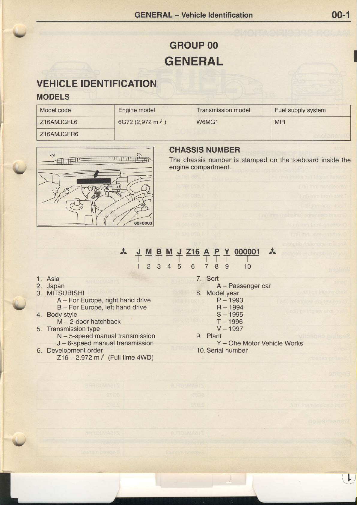
CHASSIS
The
chassis
engine
NUMBER
number is
compartment.
7I
6
supply system
stamped on the toeboard inside
000001
A
T
I
10
the
v
Asia
1.
2.
Japan
MITSUBISHI
3.
A - For Europe,
-
B
Body style
4.
M - 2-door
Transmission
5.
N - 5-speed
-
6-speed
J
Development
6.
216
right hand
For Europe, left hand drive
hatchback
type
manual transmission
manual transmission
order
-
2,972 m I
(Full
drive
time 4WD)
7.
8.
L
10.
Sort
A - Passenger
Model
Plant
Serial
year
P-1993
R-1994
s-1995
T - 1996
v-1997
-
Y
Ohe Motor Vehicle Works
number
car
Page 5
00-2
GENERAL
-
Major
Specifications
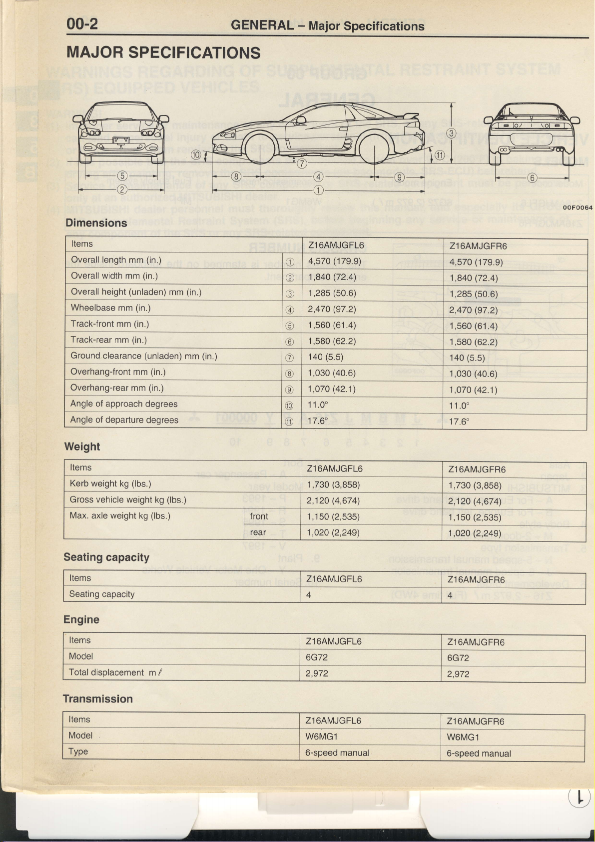
MAJOR
SPECIFICATIONS
Dimensions
Items
Overall length
Overallwidth
Overall height
Wheelbase
Track-front
Track-rear
Ground
Overhang-front
Overhang-rear mm
Angle
of approach
Angle
of departure
mm
mm
(unladen)
mm
mm
(in.)
mm
clearance
(in.)
(in.)
(in.)
(in.)
(unladen)
(in.)
mm
(in.)
degrees
degrees
mm
(in.)
mm
(in.)
Zl6AMJGFL6
4,570
o
1,84O
@
1,285
@
2,470
@
1,560
!9
1,580
@
140
€)
1,030
@
1,070 (42.1)
o
11.0"
@
17.6'
o
(179.9)
(72.4\
(50.6)
(97.2)
(61.4)
(62.2)
(5.5)
(40.6)
Zl6AMJGFR6
(179.9)
4,570
1,84O (72.4)
(50.6)
1,285
(97.2)
2,470
1,560 (61.4)
1,580 (62.2)
(5.5)
140
(40.6)
1,030
(42.1)
1,070
11.0'
17.6'
ooFoo64
Weight
Items
Kerb
weight kg
Gross
Max.
axle weight
vehicle
(lbs.)
weight
kg
Seating capacity
Items
Seating
capacity
Engine
Items
Model
Total
displacement m
Transmission
Items
Model
Type
(lbs.)
kg
(lbs.)
I
f ront
rear
Zl64MJGFL6
(3,858)
1,730
(4,674)
2,120
(2,535)
1,150
(2,249)
1,O20
Zl64MJGFL6
4
Z1
6AMJGFL6
6G72
2,972
Z1
6AMJGFL6
W6MG1
6-soeed manual
Z.I64MJGFR6
(3,858)
1,730
2,120 (4,674)
(2,535)
1,150
(2,249)
1,02O
Z1
6AMJGFR6
4
Zl6AMJGFR6
6G72
2,972
Z1
6AMJGFR6
W6MG1
6-soeed manual
LL)
Page 6
Y
13-1
T
FUEL
CONTENTS
v
GENERAL
Outline
SPEC|F|CATTONS
General Specifications
of Change
................
......2
.............2
............2
.........2
ON.VEHICLE
coMPoNENTS
Power Supply and
Fuel Pump
INSPECTION OF
........
MPI
lgnition Switch-lG
...................... 3
......................... 5
.......3
v
Page 7
13-2
GENERAL
FU EL - General/Specif
ications
OUTLINE OF
The maintenance
control
relay
CHANGE
service
fuel
and
points
pump
control
SPECIFICATIONS
GENERAL
Items
Engine
control
unit
SPECIFICATIONS
ldentification
No.
model
Vehicles without
immobilizer system
Vehicles
system
below
have been established to correspond
relay which were
with immobilizer
previously
Specifications
E2T61379
E2T61380
E2T61383
E2T61384
integrated.
<L.H.
<R.H.
<L.H.
<R.H.
to the
vehicles>
drive
vehicles>
drive
drive vehicles>
vehicles>
drive
separation of the engine
L
J
v
o
Page 8
FUEL
-
On-vehicle
Inspection
of MPI
Components
13-3
,ly
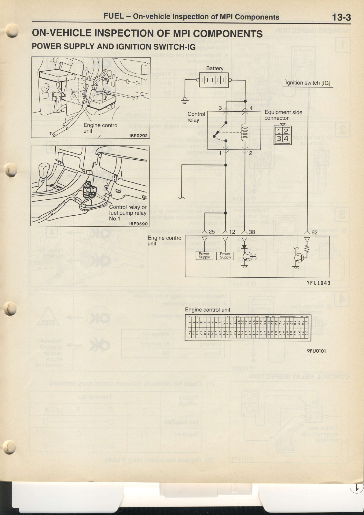
oN-vEHtcLE
POWER
SUPPLY
tNSpECTtON
AND
OF Mpt
IGNITION
SWITCH.IG
COMPONENTS
Battery
rlrlrlrlrl
lgnition
switch
[G]
Engine
unit
control
YVV
-j- -J-, L
l$il:;llG;;pi;l
Engine
control unit
pH
-\tr
V
I
A?
V
-ilri
?FU1943
9FU0l0l
Page 9
13-4
FUEL - On-vehicle
Inspection of
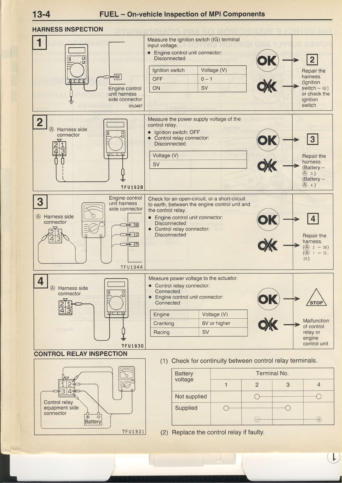
Measure
input voltage.
o
Engine control unit connector:
Disconnected
MPI Components
the ignition switch
(lG)
terminal
?FUt928
lgnition switch
OFF 0-1
ON SV
power
Measure the
relay.
control
o
lgnition
o
Control
Disconnected
Voltage
SV
Check
to
earth, between
the control relay.
o
Engine control unit
Disconnected
o
Control
Disconnected
switch:
relay
(V)
for an open-circuit,
relay
supply
OFF
connector:
the engine
connector:
Voltage
connector:
(V)
voltage
or a short-circuit
control unit and
of
the
Repair the
harness.
(lgnition
-
switch
or check
ignition
switch
oz
the
Repair the
harness.
(Battery
@
(Battery
@
Repair the
harness.
(@
(@
25)
s)
a)
z
r
-
-
-oa;
-rz,
)
CONTROL
RELAY
?FU1930
INSPECTION
?FU1931
Measure
o
.
power
voltage to
Control relay connector:
Connected
Engine
(1)
Check
control unit
for continuity
Connected
Engine
Cranking
Racing SV
Battery
voltage
Not
supplied
Supplied
(2)
Replace the control
the actuator.
connector:
Voltage
8V
(V)
or higher
between control
relay terminals.
Terminal No.
1 2 3
C
C-
--{
o-
relay if faulty.
Malfunction
of control
relay or
engine
control unit
4
---c
----@
Page 10
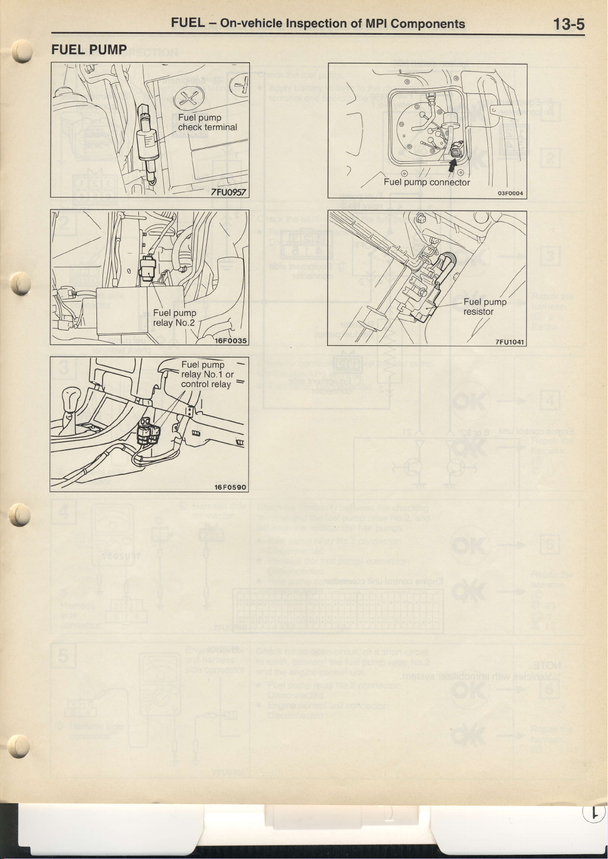
FUEL PUMP
FUEL
-
On-vehicle Inspection
of MPI
)
-t
Gomponents
13-5
r)
pump
Fuel
relay No.2
Fuel
relay
control relay
pump
No.1
or
\\
<t
11-!
:
*/
Page 11
1,3-6
FUEL - On-vehicle
lnspection of
MPI
Components
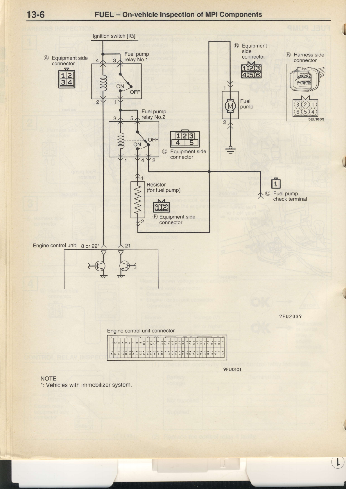
Equipment
connector
-g-
lml
il ltatl
lgnition switch
Fuel
relay No.1
|Gl
pump
Fuel
relay No.2
Resistor
(for
pump
Equipment
@
conneclor
pump)
fuel
-N/-
t@t
Equipment
O
connector
side
Equipment
@
side
connector
@
pump
Fuel
O
check terminal
Harness
connector
side
I
,l
Engine control
NOTE
-:
Vehicles
unit
with immobilizer
8 or
22*
Engine
system.
control
?FU203?
unit connector
9FU0l0l
Page 12
FUEL
-
On-vehicle
Inspection
of MPI
Components
13-7
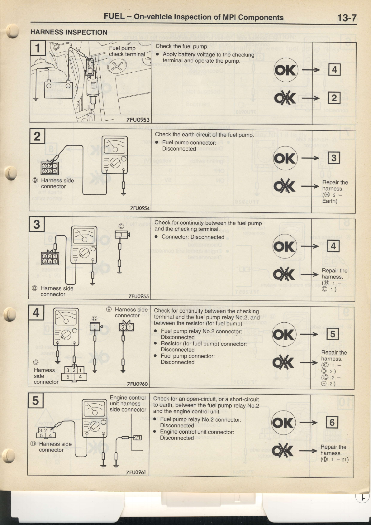
HARNESS
INSPECTION
l-Y-l
l-X-l
L____\z_J
Check the
o
Apply
battery
terminal
Check the
o
pump
Fuel
Disconnected
pump.
fuel
voltage
and
operate the
earth
circuit
connector:
to the
checking
pump.
of the fuel
pump.
Repair
the
narness.
(@zEarth)
v
Check
for
I-\-----l
l;\---=:l
tol
o
and the
o
checking
Connector:
continuity
terminal.
Disconnected
between
the fuel
pump
F
I
o
Check for
terminal
between
o
o
r
Disconnected
continuity
and the fuel
the resistor (for
pump
Fuel
Disconnected
Resistor (for
Disconnected
Fuel
pump
relay
fuel
connector:
between
pump
fuel
No.2
connector:
pump)
connector:
the
relay
pump).
checking
No.2,
and
T
Check
for
to
earth,
and
o
o
Disconnected
i
an open-circuit,
between
the
engine
control
pump
Fuel
Disconnected
Engine
relay
control
the fuel
unit connector:
unlt.
No.2
or
a short-circuit
pump
relay
connector:
No.2
Repair
the
narness.
(@t-
r)
O
Repair
the
harness.
(Ot-
z)
@
(Oz-
z)
O
Repair
the
harness.
-zr;
(@
r
Page 13
FUEL
-
On-vehicle
Inspection
MPI Components
of
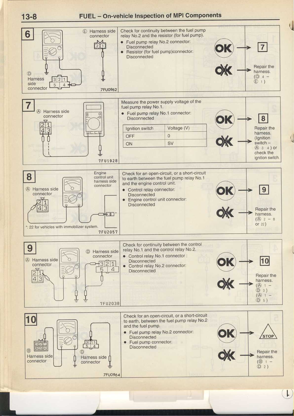
?FU1928
for continuity
Check
No.2
relay
o
o
pump
Fuel
Disconnected
Resistor
Disconnected
Measure
fuel
o
the
pump
pump
Fuel
Disconnected
lgnition
OFF
ON
and the
relay
(for
fuel
power
No.1.
relay
relay
switch
between
resistor
No.2 connector:
pump)connector:
supply
No.1 connector:
the fuel
(for
fuel
voltage of
Voltage
0
SV
pump)'
(V)
pump
the
Repair the
narness.
(O+-
r)
@
Repair the
narness.
(lgnition
-
switch
+)or
e
@
the
check
switch.
ignition
rJ
,J
tFt
I-E-l
t ____v__J
?FU2038
Check
to earth
and
o
o
Check
relay No.1 and
.
o
Check
to earth,
between
engine
the
Control
Disconnected
Engine
Disconnected
Control
Disconnected
Control
Disconnected
and
r
o
relay
control
for continuity
relay
relay
for an
between
the fuel
pump relay No.2
Fuel
Disconnected
pump
Fuel
Disconnected
pumP.
open-circuit,
for an
or
pump
fuel
the
unit.
control
connector:
unit connector:
between
control
the
No.'l
No.2
open-circuit,
the
connector:
relay
connector:
connector:
or
pump
fuel
connector:
a short-circuil
a short-circuit
No.1
relay
the control
No.2.
No'2
relay
the
Repair
harness.
(@z-s
zz)
or
the
Repair
narness.
(@t-
s)
@
(@r-
s)
O
the
Repair
narness.
(@r-
z)
O
t,
Page 14
FUEL
-
On-vehicle
Inspection
of MPI
Components
13-9
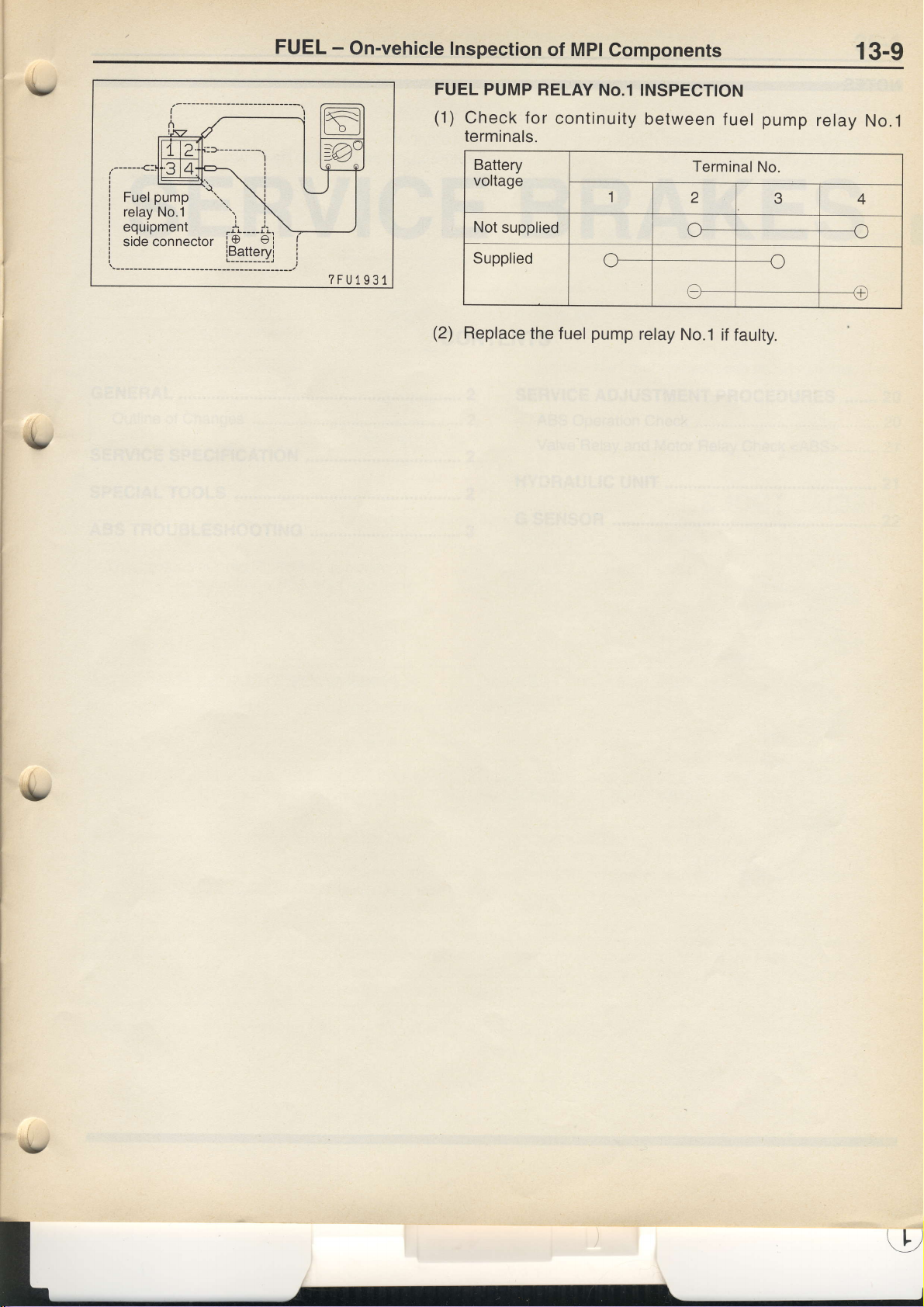
?FU1931
FUEL PUMP
(1)
Check for
terminals.
Battery
voltage
Not
supplied
Supplied
(2)
Replace
the fuel
RELAY
No.1 INSPECTTON
continuity
1
pump
between
Terminal
2
e--
relay
No.1 if
fuel
No.
fautty.
pump
3
1-)
relay
4
a)
@
No.1
rtz
Page 15
35-1
SERVICE
CONTENTS
{'
BRAKES
SERVICE ADJUSTMENT
ABS
Operation Check
Valve Relay
HYDRAULIC
G SENSOR
and Motor Relay
UNIT
PROCEDURES
Check
<ABS>
....................22
.....,.20
.....20
........21
..........21
(L,)
Page 16

35-2
SERVICE
BRAKES - General/Service
Specification/Special
Tools
GENERAL
OUTLINE
.
The hydraulic unit
.
The ABS
o
The
SERVICE
Items
Hydraulic unit
Resistance
G-sensor
SPECIAL
OF CHANGES
valve relay and
G-sensor
SPECIFICATION
solenoid
between
output
voltage
TOOLS
has been
and the
ABS-ECU have been
internal resistance
valve
speedsensor
V
made
the ABS
terminals
more lightweight and compact.
motor relay
have
been
separated
changed.
o OUT
IN
kO
installed
When
removed
When
mark facino down
from the
with
arrow
hydraulic unit.
-
4.54
-2.6
value
Standard
4.04
8.04 - 9.04
1.4 - 1.8
2.4
3.4 - 3.6
(
Tool
Number
MB991529
M8991638
M8991348
Name
ABS check
harness
ABS check
narness
Test harness set
Use
For checking
when
using
For checkino of
For checking
of ABS
the
of G-sensor
(Diagnosis
ABS warning lamp)
ABS
code display
(L
Page 17

SERVICE
BRAKES
-
ABS
Troubteshooting
35-3
i.
t
ABS
STANDARD
lnspection
(Refer
TROUBLESHOOTTNG
FLOW
No
diagnosis
or MUT-ll
communtcate
to P.35-14.)
code
can't
chart for
trouble
OF
symptoms
DIAGNOSTIC
Verify
TROUBLESHOOTING
complaint
Reoccurs
I
VY
I
oiaonosis
J
Read (and
diagnosis
(fault
memories
them.
codes
duration
(Refer
.----l-
Read
trouble
Inspection
(Refer
chart for
to P.35-6.)
cooe oisotaveol-
write
down)
and
tfre
and
are
how
erased).
to P.35-5.)
'
t
codes
Diagnosis
diaqnosis
all
displayed
service
manv
And
F""d,
l(Rerer
codes
c
oes not
I
"S""rb
to P.35-4.)
iagnosis
ciata
times
erase
No
Diagnosis
code displayed
reoccur
a"d"
code
displayed
I ntermittent
code
-t
o Diagnosis
N
I
malfunction
code
NOTES
The
Phenomenon
System
{t
ABS
ABS
braking
Diagnosis
WITH
phenomena
check
REGARD
listed
sound
operation sound
operation
(Long
distance)
detection
TO DIAGNOSIS
in
the following
Explanation
When
theengine
performed,
1.
sound
2.
sound
3. When
brake
(Thump:
For road
for vehicles
advise
being
too
condition
can
table
phenomenon
of
starting
the
tfr"
compartment,
and is
of the motor
generated
is
ABS
operates,.sound
application
suspension;
surfaces
with
ABS
customer
overconf
vary
depending
are not
"n
not
abnormal.
but
this is
an
abnormalitv.
inside
the
atong
with vibration
and release.
squeak;
rr"
can sometimes
to
drive
safely
ident.
on the
because
ABS hydraulic
of the
generated
is
from
tyres)
longer
be
on such
ioads
diagnosis
the
system
unit
brake
the vehicle
thanlhat
by lowering
code.
operation
check
operation (whine)
pedal. (scrapfng;
chassis
for
other
vehicles.
the
vehicle
is
deing
oib
to repeated
X.corJingty,
speed
"nJ"not
Page 18

35-4
SERVICE
BRAKES
-
ABS
Troubleshooting
W
4
NEE
diagnosis code
When
No.24
is output
DIAGNOSIS
DIAGNOSIS
With thE MUT.II
Connect
diagnosis
Caution
Turn the
necting the
Without
1. Use
2.
the MUT-II
the MUT-II
the special
No.1.
Turn the
the diagnosis
lamp.
FUNCTION
CODES CHECK
codes.
ignition switch
MUT-II.
ignition switch
to the diagnosis
off before connecting
tool to eadh diagnosis
to ON
codes
from the flashing of
connector, then check
and then take a
or discon-
connector
the ABS warning
terminal
reading
of
oN
OFF
secs.
r
Pause time Tens
3 secs. signal
no diagnosis
When
Place
division
2 secs.
is
code
Units
signal
14tO173
output
Page 19

SERVICE
BRAKES
-
ABS
Troubteshooting
35-5
ffiG:-=\\
U\\ED
ERASING
with
the
MUT-rr
1.
Connect
erase
the
NOTE
Commands
memory
stop the
used
again.
2.
Check the
has
been
Without
1.
the
Use the
No.1.
2. Turn
the--ignition
switch
below.
codes
will
DIAGNOSIS
the
diagnosis
cannot
has
been erased.
engine
CODES
MUT-II
codes.
be received
and
start it
diagnosis
erased.
MUT-II
special
tool
to
switch
off
and
on ten
Once this
has
be erased.
to
the
To
again.
codes
earth
diagnosis
to
ON and
times
been
diagnosis
from
the
check
to
the
The
MUT-II
confirm
connector
turn
as shown
done,
all
in
of the
connector,
MUT-II
diagnosis
after
codes,
can then
that
the
memory
terminal
the
stop
lamp
the
illustratioh
diagnosis
then
the
be
&
lgnition
ABS
warning
ABS-ECU
memory
switch
lamp
ON
OFF
ON
OFF
j
within
3sec.
i
#
within
i
i
1
sec.
First
within
i
i
1
sec.
Second
i
I
Third
i
within
;
t
sec.i,
T;rh*
i
i
Rtter
_i
erasing
14CO120
1
second,
is
complete.
Page 20

35-6
SERVICE
BRAKES
-
ABS
Troubleshooting
INSPECTION
Inspect according
Diagnosis
No.
code
11
12
13
14
15
16
21
22
23
24
26 G
CHART
to the inspection
Inspection
Front right
left wheel speed
Front
Rear right
Rear left
Wheelspeed
Power
right wheel speed
Front
left wheel speed sensor
Front
right wheel speed sensor
Rear
Rear left
sensor
FOR DIAGNOSIS
chart
item
wheel speed sensor
sensor
wheel speed sensor
wheel speed sensor
sensor
supply system
wheel
speed
sensor
CODES
that is appropriate
sensor
for the malfunction
Diagnosis
Open
content
circuit
Abnormal output
Short circuit
Ooen-crrcuit.
abnormal
short-circuit
signa.
output
signal
or
code.
Reference
35-7
35-8
35-8
35-9
35-9
page
38
41
42
43
44
45
46
47
48
51
53
63
switch system
lamp
Stop
Front right solenoid
left solenoid
Front
Rear right solenoid
Rear left solenoid
Front right solenoid
left solenoid
Front
right solenoid
Rear
Rear left solenoid
Valve relay
Motor relay,
valve
valve
valve lN
valve
valve OUT
valve OUT
motor
ABS-ECU
lN
valve
lN
lN
valve OUT
OUT
35-1 0
1
35-1
35-12
35-1 3
Reolace
ECU.
the
ABS-
Page 21

SERVICE
BRAKES
-
ABS
Troubteshooting
35-7
INSPECTION
9ode
The
speeo
Measure
E-10
.
.
{,
No.l1
ABS-ECU
sensors.
at the
Disconnect
sure from
Resistance
73,
OK: 1.4
the
69 and 70,71
-
PROCEDURE
,12,13,14
determines
ABS-ECU
the
connector
harness
values
1.8
kO
that
connector.
and mea-
side.
between
and 72,24
46
an open
Wheel
and
and
speed
circuit
FOR
sensor
occurs
in
Check
A-12,
Wheel
DIAGNOSIS
open
more
than one
the
followinq
A-33,
C-26,
speed
sensor inspection.
CODES
circuit
line
of wheel
conn'ectors.
E--i3
and
E-15
Probable
a
Malfunction
a
Malfunction
a
Malfunction
cause
of
wheel
of wirinq
of ABS-ECU
speed
harness
Check
wheel
and repair
Replace
sensor
or
the
harness
speed
sensor
if necessary.
the
wheel
connector
wire
between
and ABS-ECU.
speed
sensor.
each
v
Page 22

35-8
SERVICE
BRAKES
-
ABS
Troubleshooting
No.15
Code
speed
A wheel
circuit).
Wheel speed
soeclron.
speed sensor
Wheel
spectron.
Wheel
sensor
sensor
output
speed sensor
outputs an
installation
abnormal signal
in-
voltage in-
(Abnormal
(other
Wheel speed
Check the
wheel speed sensor
and
than an
repair
output
if necessary.
signal)
open or short-
inspection.
sensor
harness
wire between
ABS-ECU,
and
Probable
.
lmproper
o
Malfunction of
o
Malfunction
o
Malfunction
.
Malfunction
.
Malfunction of
each
cause
installation of
wheel
rotor
of
of wheel bearing
of wiring harness
ABS-ECU
wheel speed sensor
sensor
speed
Replace the wheel speed
Replace the rotor.
or connector
sensor.
Gode
The voltaqe
specified
output.
No.l6
value.
Caution
lf battery
returns
Before
Measure
E-10.
o
r
to standard
carrying
at
Disconnect
from the
sure
the engine.
Start
-
Body earth
83
System
OK:
Power supply
ABS-ECU
of the
lf the voltage
voltage
drops
out
the ABS-ECU
the connector
harness side.
Voltage
voltage
power
supply drops
relurns
or
value,
following
the
connector
mea-
and
between
system
to the specified
lower or
rises during
this code
is no
inspection,
rises higher
value, this code
inspection,
longer output.
check
following connectors.
the
Check
C-59, C-66
C-25,
trouble
Check
than the
no longer
is
this code
the
and C-78
symptoms.
Probable cause
.
Malfunction
.
Malfunction of ABS-ECU
will be output
battery
level,
of wiring harness
or connector.
as well.
refill it if necessary.
and
the harness
Check
ignition-switch and the
reparr rl necessary.
lf the
voltage
wire between
ABS-ECU,
the
and
tI)
Page 23

SERVICE BRAKES
-
ABS Troubteshooting
35-9
Code No.21
These
codes
o
When
does
.
Wnen
.
When the
due to
Measure
E-1 0.
.
Disconnect
sure
.
Resistance values
73,
OK: 1.4
are output
an open
not
output
a chrpped
sensor output
a defective
at the ABS-ECU
the connector
from
the harness
69 and 70,71
-
1.8 kf)
,22,23,24
at the followinq
circuit cannot
any signal
ptugged-up
or
sensor or a waroed
between
and 72,74
be fou'nd,
during
drops
connectors
and mea-
side.
46
Wheel
rotor
and anti-lock
and
and
speed
times:
but more
driving
tooth,
rotor.
at 8
sensor
than one wheel
km/h
or higher.
etc. is detected.
control is
continuouslv
Check
the following
A-12, A-33,
short
circuit Probable
speed
sensor
carried out
C-26, E-13
connectors.
and
E-15
.
Malfunction
o
Malfunction
o
Malfunction
o
Malfunction
.
Malfunction
cause
of wheel
of rotor
of wheel
of wiring
of ABS-ECU
speed
bearino
harnesi
Check the harness
wheel
speed sensor
and repair
Replace
Replace
the wheel
the rotor.
sensor
or
connector
wire
if necessary.
speed
between
and ABS-ECU,
each
sensor.
,s,
&
Code No.26
signal
Output is
.
.
Check
Measure
o
.
.
Check the
abnormal)
provided
G-sensor output
G-sensor
Disconnect
ments
lgnition
Voltage
OK: 2.3-2.7
system harness
G-sensor.
at ABS-ECU
connectors
on harness
switch:
between
following
G-sensor
in
the following
drops
below 0.5V or rises
is
(Refer
to P.35-22.)
connector E-1
and make
side.
ON
No.62
and 45
V
connector.
0.
measure.
(open-,
above 4.5V
system
cases.
broken or shorted
E-10
short-circuited
Replace
Check the following
Check trouble
Check harness
ECU,
Replace
or
G-sensor
and repair
ABS-ECU.
Probable
o
.
o
connector.
symptoms.
between
if necessary.
cause
G-sensor
Harness
ABS-ECU
defective
and
connector defective
defective
D-27
G-sensor and ABS-
;
Page 24

35-10
SERVICE
BRAKES
-
ABS
Troubleshooting
corle No-38 Stoo lamp
following
at the
output
are
codes
These
a"
WH;ih;
for
on
.
wd;
lamp
stop
the
Does
oft
switch
Measure
.
Disconnect
measure
.
Stop
o
Voliage
OK:
iiop
minLtes
15
Aa6-ECU
inl
switch
lamP
stoP
normallY?
ABS-ECU
at
the
at
switch
lamp
6etween
System
ramp
dr
system.
the connector
harness
ON.
36
voltage
is
swiicrr
although
more
Oetermines
illuminate
connector
side.
-
bodY
switch
not b5
inat
ancl
E-1 0.
and
earth
times:
turned
ABS
the
there
system
(when the
off
not operating)
is
opeh
is an
stop
circuil'in
lamp
Stop
inspection.
lamp
Stop
the
Check
No.17
fuse
if necessary.
repair
the
Check
C-65
C-50,
switch
lamp
harness
switch
inspection
switch
harness
and
following
C-79
and
stavs
the
of
between
ABS-ECU'
the
connectors.
Probable
a
Malfunction
o
Malfunction
a
Malfunction
installation
dedicated
and
cause
of stop
harness
of
ABS-ECU
of
Replace
lamp
or
switch
connector
stop
the
lamp
switch
Check
following
the
connector.
the
Check
and
switch
necessary.
harness
ABS-ECU'
the
between
and
stop
reparr
lamp
ll
Page 25

SERVICE
BRAKES
-
ABS
Troubteshooting
35-11
Code No.41,
The ABS-ECU
there
is
flows in
Solenoid
(Refer
to P.35-21.)
Measure
78
and ABS-ECU
r
Disconnect
measure
.
Continuity
terminals
OK:
HU
side
ABS-ECU
side
HU
side
ABS-ECU
side
always monitors
an open or
the solenoid
valve insDection
at hydraulic
at the harness
between
Conlinuitv
1234
tttl
30 31 78
5678
lttl
58
42,
43, 44,
short-circuit
even
though the ABS-ECU
unil
connector A-
connectors
the
connector
side.
the following
59 50
45, 46,
the solenoid
in the
E-10.
and
79
51
47,48
valve
solenoid
Solenoid valve
drive circuit. lt
coil or in a harness:
turns on it,
Check the
A-78.
Check the
draulic
rs necessary.
determines
and vice
following
C-25.
C-59 and E-10
harness
unit and ABS-ECU,
when
versa.
that
no
currenl
connectors.
between
and repdir
Probable
a
Malfunction
a
Malfunction
a
Malfunction
the hv-
cause
of harness
of hvdraulic
of Ai3S-ECU
or
connector
unit
Replace
the ABS-ECU.
Page 26

35-12
SERVICE
BRAKES
-
ABS
Troubleshooting
Code
i:[1!_ AgS-ECU
Measure
94.
.
.
Measure
o
.
No.51
lCommentl
,eO to i iolenoid
sropf
cohiinues
valve
relay.
Solenoid
(Refer
to be
is off,
relay
Thi6 diagnosis
at
Disconnect
the
sure at
between
Voltage
System
OK:
at
Disconnect
measure
Resistance
OK:60-120O
valve
P.35-21.)
to
valve
ABS-ECU
at
Valve
continually
supplied
the
the connector
harness
voltage
the connector
the
between
insPection
relaY
monitors
even
coil
to five
ABS-ECU
is then
code
relay connector
side.
-
bodY
5
connector
side.
harness
82-47
though
or more
judges
and
earth
E-10.
the
output.
A-
mea-
and
solenoid
solenoid
the
solenoid
thal there
circuit.
drive
valve
coils even
problem
is a
Replace
Check
link No.7
necessary.
Check
A-94 and
no currenl
lf
relay
thougn
wltn
the
the
and
the
or if.current
is.on.
_tne
tne Ats5
valve
harness
valve
tollowing
or C-96
C-94
is being
solenolo
valve
relaY.
between
relay,
connectors.
and
fusible
repair
Probable
o
Malfunction
.
Malfunciion
o
Malfunction
o
Malfunction
if
cause
of valve
of
of
of hydraulic
relaY
harness
wiring
ABS-ECU
Check
relay
necessary.
unit
harness
the
ABS-ECU,
and
or connector
between
and
valve
rePair
if
Measure
78 and
.
.
HU SidE
ABS.ECU
side
HU
ABS-ECU
side
Measure
77 and
.
.
HU side
at
ABS-ECU
Disconnect
measure
Continuity
terminals
OK:
side
valve
Disconnect
sure at
Continuity
terminals
OK:
hydraulic
connectors
the connector
harness side.
the
at
between
Continuity
1234
3|o
5678
5|u
hydraulic
at
ielay
the connector
harness
the
between
Continuity
connector
unit
the
t|u ?1,
311
5|o
51,
connector
unit
connector
side.
the
11
A-
E-10.
and
following
J,
A-
A-94.
mea-
and
following
Check
A-78,C-25
Check
draulic
It necessary.
Check
A-77 and
the
unit
the
A-94
and
following
the
E-10
harness
ABS-ECU,
and
following
connectors.
between
connectors'
the
and
hY-
repair
the
Check
unit and
draulic
if necessary.
harness
valve
between
relay, and
the
repair
hY-
Reolace
ABS-ECU.
the
Page 27

SERVICE
BRAKES
-
ABS
Troubleshooting
35-13
Code No.53
These
codes
when
not
operating,
When
s.etonds
When the
are output
the motor
the
motor relay
or more
motor relav
Caution
Because
should
MUT-II
ls
the sound
head?
A?:-ffi"t
Measure
77.
.
Disconnect
sure
.
Voltage
OK:
force'driving
be started
actuator
of the motor
relav
at motor
the
at the harness
between
System voltage
Motor
at the followinq
rela!
is on
etc.)
is off
(motor
continues
does not ooerite
test
insnection
relav
connector
connector
side.
5 - body
relay,
bul no
but
a signal is input
of
and
left to run
operating
(Rerer
and mea-
earth
motor
times:
sign-al is input
operating,
etc.)
the motor
for
Yes
to
A-
to the molor
to the motor
monitor
monitor
by means
a while
Check the
draulic
rr necessary.
Check the harness
link
necessarv.
after
unrt
No.7
and motor relay,
(motor
line
line for
5
of the
actuator
testing
harnesses
and ABS-ECU,
between
between fusible
Probable
o
.
is
.
.
is
completed.
the hv-
and repdir
repair
and
Malfunction
Malfunction
Malfunction
Malfunction
test
will
if
cause
of motor relav
of wiring harness
of hvdraulic
of ABS-ECU
drain
unit
the
or connector
battery,
the
engine
Measure
.
.
Measure
.
.
y.Blo_rrii"r",'"n
at ABS-ECU
Disconnect
sure
Resistance
OK:
Disconnect
sure at the harness
Resistance
earth
OK: 0. 1-0.3O
the
at the harness
78-88O
at ABS-ECU
connector
belween
the
connector
between
inspection (Refer
connector
and mea-
side
77-82
connector
and mea-
side.
65 - bodv
E-10.
E-10.
ro
Check the
draulic
unit and ABS-ECU,
if
necessary.
necessary.
Replace
Repair
Replace the
the
harness
hvdraulic
ABS-ECU.
between
Motor
the hv-
and reodir
earth. repair
unit.
Repair
Check
the harness
relay
and ABS-ECU,
essary.
if
between motor
and repair if
nec-
Page 28

35-14
INSPECTION
an understanding
Get
CHART
SERVICE
TROUBLE SYMPTOMS
FOR
the trouble symptoms
of
BRAKES
-
ABS Troubleshooting
check according
and
to the
inspection
procedure
chart.
Trouble symptom
Communication
possible.
is not
the ignition
When
not illuminate.
After the engine starts,
ABS operation
Faulty
with MUT-II
key is turned to
lamp remains
the
Caution
1. lf
steering
with low
sudden
customer,
movements are
frictional
braking
check
resistance, or
is not being applied.
if the
problem
2. During ABS operation,
phenomenaare
prevent
the wheels
to intermittent
due
from locking and
Communication
Communication
"ON"
(engine
illuminated.
Unequal
Insufficient braking
ABS operates
ABS operates
ing
Large brake
braking
conditions
made
with
with ABS only
stopped),
power
under
before
pedalvibration
when driving at
when
occurred
the brake
pedal
changes
is
possible.
systems
all
the
on both sides
power
normal braking conditions
vehicle stops under
is not
possible.
is not
ABS warning
(Caution
2.)
high speed,
passing
Because
while driving
vibrate or
may
over
of this,
bumps,
under such
may not be able
in hydraulic
not
an abnormality.
lamp
does
normal brak-
or when driving
the ABS
when
may operate even
getting
conditions
pressure
inside the brake
on
road
Reference
page
5
JC- tO
35-17
35-1 8
surfaces
Inspection
proceoure
No.
1 35-1
2
3
4 35-17
5
though
information
from the
as these.
to be depressed.
Such
line
to
Page 29

SERVICE
BRAKES
-
ABS Troubleshooting
35-15
,(,
rNspEcnoN
Inspection
Communication
(Communication
The cause
diagnosis
Measure at the diagnostic connector
.
Voltage between 16 and earth
OK: System
Measure
.
Continuity between 4 and
o
Continuitv between 5 and
OK:
Reolace the MUT-ll
is
line.
the diagnostic connector
at
Cohtinuitv
pRocEDURE
Procedure 1
MUT-II is not
with
with all systems
probably
a
voltage
defect in the
earth
earth
power
supply system
FoR TRoUBLE syMproMs
possible.
is not
possible.)
(including
Check the
A-11x. C-65. C-67 and
following connectors.
earth)
for the
C-79
Probable cause
o
Malfunction of the connector
.
Maliunction of the harness wire
Check the harness wire between the
power
repair if necessary.
and
Check the harness wire between the
diagnosis connector and earth, and
parr
rr necessary.
supply
and
diagnosis
connector
re-
ry
Page 30

35-16
SERVICE
BRAKES
-
ABS Troubleshooting
Inspection
procedure
Communication
(Communication
When communication
in the ABS-ECU
circuit
Measure at diagnosis
ABS-ECU connector
and
.
Disconnect the connector
the harness side.
sure at
.
Continuity
terminals
OK: Continuity
ABS-ECU
side
Diagnosis connector
stoe
Measure at
.
Disconnect the
sure at the harness side.
o
lgnition switch
.
Voltage between
OK: System
ABS-ECU connector
with the MUT-ll
connector C-70
between
connector and
ON
83 body earth
voltage
2
MUT-II is not
with
with ABS only
power
E-10.
and mea-
following
the
38
7
is not
circuit or an open circuit
68
1
E-1 0.
mea-
possible.
is not
possible,
Check
C-27,C-70
Gheck the
C-25, C-66
possible.)
probably
the cause
in the diagnosis
is
following connectors.
the
E-10
and
following connectors.
and C-78
an open
output circuit.
Probable cause
.
Blown fuse
o
Malfunction of wiring harness or connector
o
Malfunction
of ABS-ECU
the harness between the ABS-
Check
ECU and diagnosis connector, and
pair
if necessary.
Check the
inside the
ECU, and repair
harness
junction
if necessary.
between
block
fuse No.3
ABS-
and
re-
Measure
o
Disconnect
sure at the
.
Continuity
earth
OK: Continuity
ABS-ECU connector
at
the connector and
harness side.
between
55, 56 - body
E-10.
mea-
Page 31

SERVICE
BRAKES
-
ABS Troubleshooting
35-17
Inspection
When ignition
ABS warning
lf the lamp
supply circuit,
and the ABS-ECU.
Fuse inspection,
Measure
.
Disconnect
sure at the male
o
lgnition
o
Does
illuminate
earthed?
OK: llluminates
Check the harnesses
ABS-ECU
Repair,
Procedure
key
lamp
does not illuminate,
a_blown lamp
Multi-purpose
at connector
switch:
the ABS
and
if necessary.
D-16
the
ionnector and mea-
oin.
ON
warning lamp
when
connector D-16.
3
is turned
o'ON"
to
does not illuminate.
the
bulb, an open
terminal
between the
cause may
fuse
7 is
be: an open
cirbuit between
(engine
Refer
a Blown Fuse.
Check whether
bulb is burnt
Check the followinq
C-68.
stopped),
circuit in the lamp
the ABS warning
to Inspection
the
ABS warning
out.
D-04
C-78.
ana D-45
power
la'mp
Service Points
lamp
connectors.
Probable
o
Blown
.
o
for
fuse
Burnt out
Malfunction
ABS warning
cause
Replace
lamp
the ABS
of wiring hirness
bulb
or connector
warning
lamp
bulb
Inspection
Even
remains
The cause is
Procedure
after the
illuminated.
probably
NOTE
This trouble
normal)
Disconnect
o
Does the ABS warning
.
Disconnect
.
lgnition
o
Does the ABS
Check the harnesses
ABS-ECU.
symptom is limited
and the
switch:
diagnosis
connector D-16
ABS-ECU
ON
warning
Repair. if
necessarv.
4
engine is
a short-crrcuit in
code is a normal
and turn
lamp remain
connector
lamp
switch off?
belween
the combination
started,
the ABS warning
the ABS
to cases
the ignition
illuminated?
E-10.
switch
warning
lamp illumination
where
communication
diagnosis
to ON.
meter
and the
code.
lamp
circuit.
with
Probable
a
a
a
the MUT-II
Replace
the
cause
Malfunction
Malfunction
Malfunction
combination meter.
of combination
of ABS-ECU
of wiring
possible
is
meter
harness
(ABS-ECU
power
supply is
Page 32

35-18
SERVICE
BRAKES
-
ABS
Troubleshooting
Inspection
Brake
This varies
pioOfem
out the
Wheel speed
speclron
operation
depending
Ciagnbsis
following
Procedure
5
is abnormal.
driving
on the
isAifficutt.
inspection
sensor
Howeier,
installalion
conditions
if a normal
in-
the
and
diagnosis
Rotor
surface
road
code
inspection.
conditions,
is displayed,
so
carry
Probable
a
lmproper
a
lncorrect sensor
a
Foreign
a
Malfuhction
a
Malfunction
a
Malfunction
o
Malfunction
a
Malfunction
installation
material adhering
cause
harness
of wheel
rotor
of
wheel bearing
of
hydraulic
of
ABS-ECU
of
Replace
of wheel
contact
to
sensor
speed
unit
wheel
the
sensor
speed
wheel speed
speed
sensor
sensor.
the
Check
A-33, C-26,
A-12,
Measure
.
Disconnect
sure at
.
Resistance
nals
OK:
(The
ihould
spections
the
Check
E-10
following
ABS-ECU
at
the
46-73,
-
1.4
sensor
be
are carried
following
harness side
the connector
69-70,71-72
moved
connectors.
E-15
and
E-13
connector
and
value between
1.8 kC)
harness
and
connector
and
these
while
out.)
connector.
C-29.
mea-
terml74'75
in-
Page 33

SERVICE
BRAKES
-
ABS
Troubteshooting
35-19
SERVICE
The
following
1.
When
Item
No.
11
DATA
the
12
13
14
16
ABS-ECU
age
17
3B
G-sensor
Stop lamp
REFERENCE
items
can
system
Check
Front-right
sensor
Front-left
Rear-right
sensor
Rear-left
is
ltem
wheel
wheel
wheel
wheel
power
output
switch
be read
normal
speed
speed
speed
speed
supply
voltage
TABLE
by the
sensor
sensor
vott-
MUT-II
from
Checking
Do
a
lgnition
monitor
Vehicle
Perform
Depress
the
ABS-Ecu
Requirements
test run
switch
power
voltage
is
stationary.
actual running.
the
brake
supply
pedal.
input
voltage
data.
and valve
NormalValue
Vehicle
displayed
speedometer
and
identical.
System
2.4
Displayed
rises
drops
ON
speeds
MUT-II
voltage
-
2.6V
value
above
below
on the
are
or
2.5
V.
2.
When
When
ACTUATOR
The
MUT-II
the
the
diagnosis
activates
ABS-ECU
TEST
NOTE
1.
lf
the ABS-ECU
2'
Actuator
testing
Activation pattern
Hydraulic
pressure
increases
Hydraulic
Sote-
pressure
noid
vatve
l19r9s ,. i
Hydraulac
pressure
decreases
40-45
ON
Pump
motor
OFF
testing
exceeds
-l
I
i
i
i
!
i
tr
i
msi
shut
off ABS
system
stops
REFERENCE
the
following
runs
down,
is
only
10
km/h,
Start
of forced
actuation
actuator
possible
forced
Release
operation.
the ABS-ECU,
the
TABLE
actuators
when
actuation
for
testing.
testing
cannot
the vehicle
willcancels.
ACTUATOR
No.
01
02
03
the
MUT-II
pedal.
brake
display
be
carried
is
stationary.
TEST
Item
Solenoid
wheeland
Solenoid
and motor
Solenoid
wheeland
valve
valve
valve
data
will
be unreliable.
out.
lf
the vehicle
SPECIFICATIONS
for front-right
motor
for front-left
for
rear-right
motor
wheel
OFF
speed
Solenoid
pump
hydraulic
inspection
during
valves
motors
unit
actuator
in
the
(simple
mode)
and
o4
Solenoid
and motor
valve
for rear-left
wheel
Page 34

35-20
SERVICE
BRAKES
-
Service
Adiustment
Procedures
Main
wiring
harness
M8991638
i4co13o
SERVICE
ABS
WHEEL
2. Disconnect
3.
OPERATION
SPEED
Lift up
1.
specialtool
iotate
rotation
circuit
Wheel
speed
sensor
Terminal
No.
Output
When
ADJUSTMENT
SENSOR
vehicle
the
the ECU
to measure
wheel
the
per
second,
tester
or an
Front
19
20
voltage
measuring
70 mV or
When
lf the output
4.
reason
o
Faulty
replace
So
measuring
mV
100
could
wheel
the
CHECK
OUTPUT
release
and
harness
from
to be
P-P
voltage
be as
speed
wheel sPeed
measured
check
and
oscilloscope.
left
Front
right
14
15
with a
more
with an
more
or
is lower
follow:
sensor.
PROCEDURES
VOLTAGE
parking
the
connector
harness
the
at
the output
Rear
16
17
circuit
tester:
oscilloscope:
the
than
sensor.
CHECK
brake.
and
connector'
side
approximately
voltage using
left
above
Rear
18
46
values,
use
112-1
right
the
a
the
Inspecting
the
Use
from each
form
o
Start
1st
Wave
following
the engine,
gear
(vehicles
wheels
manually
NOTE
1.
Check
connector
wave
The
2.
vehicle
the
The output
3.
low, and
high.
Forms
method
wheel sensor
With An Oscilloscope
to observe
with an
and
rotate
the
(vehicles with manual
with automatic
that they
so
the connection
before
form
using
measurements
is
actually
voltage will be
similarly
it will be
transmission).
rotate
the
of
oscilloscope.
the
moving.
small
large
the output
voltage
wave
oscilloscope .
wheels by
front
transmission)
constant
at a
sensor
also
can
when the
when the
engaging
range
D
or
Turn the
speed.
harness
be taken
wheel
wheel
speed
speed
rear
and
while
is
is
Page 35

sERVlcE
BRAKES
-
service
Adjustment
procedure/Hydrautic
Unir
3S-21
$)iu""JrJy
VALVE
<ABS>
Remove
Battery
Continuity
Continuity
voltage
RELAY
the
splash
no voltage
with
voltage
AND
shield
Terminal
MOTOR
(FR)
and remove
No.
1
G-
0-
--{
--€
RELAY
the relavs.
3
CHECK
4
c-
--{
5
/lrel
,EL- I
€jFJ-Fffir
lf.X.Xetl
HYDRAULIC
UNIT
INSPECTION
SOLENOID
Measure
Standard
Solenoid
Front
Front
Rear
lN
Rear
lN
Front
OUT
Front
OUT
Rear
OUT
Rear
OUT
MOTOR
connect
the
hydraulic
VALVE
the
resistance
value:
valve
(right
lN
lN
(left
side)
(right
(left
side)
(right
(left
(right
(left
side)
side)
side)
side)
side)
side)
OPERATION
the
battery
unit
motor
CHECK
and
Caution
The
battery
power
should
second.
between
Measurement
terminals
-
1
11
11 11
-- | |
3-11
2-11
5-11
8-11
7-11
6-11
CHECK
check
to
operating
not
be applied
terminals.
Resistance
terminals.
8.04
4.O4
be
sure
can
be heard.
-
9.04
-
4.54
that
for
between
O
A
the
sound
more
than
of
1
Page 36

35-22
SERVICE
BRAKES
-
Hydraulic
UniUG-Sensor
INSTALLATION
BRAKE
1.
Connect
illustration.
(1)
From
(2)
From
(3)
From
(4)
From
(5)
From
and
(6)
From
and
SERVICE
PIPE
the
hydraulic
hydraulic
hydraulic
hydraulic
master
rear
master
rear
POINT
INSTALLATION
tube
R.H.
L.H.
to the
unit
unit
unit
unit
cylinder
line)
cylinder
line)
hydraulic
front brake
to
rear brake
to
rear brake
to
front brake
to
to hydraulic
to
unit as
(L.H.)
(R.H.)
(L.H.)
(R.H.)
hydraulic
unit
shown
(front L.H.
unit
(front
in the
R.H.
line
line
MB991
348
G-SENSOR
INSPECTION
1. Disconnect
special
connector.
Turn the
2.
following
Between
Standard
With the
that
so
take a
Between
Standard
voltage
lf the
4.
sure
to be
earth
and
the G-sensor
tool between
ignition
outPut
terminals
value:
special
label
the
reading
of
terminals
value: 3.4
is outside
that
wires,
switch
voltage.
No.2 and
-
2.4
tool still
surface
following
the
No.2 and
-
is
there
replace
connector
terminals
the
take
to ON
2.6
connected,
is facing
3.6
the standard
no abnormality
the G-sensor.
and
No.3.
V
straight
output
No.3.
V
connect
and
the disconnected
of
reading
a
secure
voltage'
value, after
the G-sensor
down,
power
in the
of
and
checking
supply
the
the
then
Page 37

528-1
SUPPLEMENTAL
RESTRAINT
0
SYSTEM
CONTENTS
TROUBLESHOOTING
AIR
(SRS)
Standard
Inspection
Inspection
Diagnosis
lnspection
lnspection
MODULE
BAG
Diagnostic
of
Flow
for
Chart
procedure
.........
Code
for
Chart
Procedure
AND
Troubleshooting
Diagnostic
Classified
Trouble Symptoms
for Trouble
Codes
CLOCK
.......".......'..'
by
.".-...'.'.'."
Symptoms'."'.'.
SPRING
.."...4
4
'.......
....'... 5
12
12
14
......
5
o
Page 38

52B'-2
SRS
-
SRS
Service
Precautions
SRS
SERVICE
1. In order
accidental
from
servicing,
precautions
manual.
not use
2.
during
the
this
Do
near SRS
P.52B-4.
on
3.
Never
Attempt
Components:
.
SRS
o
Clock
.
Air
Bag
(Driver's
SRS-ECU
PRECAUTIONS
to avoid
any electrical
components,
air bag
Spring
Module
injury
deployment
read and
procedures
and
Repair
to
control
front
or
side
connector
yourself
to
of the
carefully
described
equipment
test
except
unit
those
Following
the
(SRS-ECU)
passenger's
others
or
air bag
follow
all
in
or
on
specified
side)
Do not attempt
4.
the SRS.
replace
faulty,
the
lf
any
wiring
the
replace
following
table.
repair
to
the connectors
of
repair the
or
the wiring
harness.
harness
are diagnosed
wires are
lf the
wiring
harness
connectors
faulty,
as
diagnosed
according
as
of
to
Page 39

SRS
-
SRS
Service
precautions
528-3
16
to
19
21
pins,
yellow
Body
wiring
module
Body
passenger's
Body
Body
Body
Body
Body
(Drive/s
wiring
wiring
wiring
wiring
harness
wiring
wiring
harness---
harness
harness
harness
harness
harness
side)
-
side)
-
--.+
---r
-
.-+
Clock
spring
Air
bag
Diagnosis
Junction
Junction
SRS
Earth
block
block
warning
-
module
(Front
connector
(fuse
(fuse
lamp
Air
bag
No.1
No.1g)
1
)
Correct
wiring
Corrective
Correct
wiring
clock
Correct
wrnng
Correct
wiring
Correct
wiring
or
harness.
spring.
or
narness.
or replace
harness.
or replace
harness.
or
harness.
action
replace
Replace
replace
replace
each
each
each
each
body
Insulating
6.
SRS
and
7.
whenever
functions
8.
Make
you
9.
lf
NOTE
SERIOUS
THE
tape
components
clock
sprino
you
should
b*1"
-finish
servicirig
properly.
certain
have
PROCEDURES
that
the
questions
any
INJURY
CAN
ignition
AND
Battery
not
be
subjected
gryjp
about
RESULT
oa!1s
ql
tne
snb,
switch
the
is
SRS,
FROM
EQUIPMENT
5.
After
seconds
fottowing
enough
even
serious
deptoyment
immediatery
nected.
to
hear
over
the
vehicre
check
oFF
pr""r"
warning
when
the
.oitaciyour
UNINTENDED
SPECIFIED
disconnecting
or
m_ore^before
work.
vottage
after
injury_may
93.C,
The.sRS
to
the
battery
if
work
after
so
deptoy
result
the
remove
aflei[aintins
iamp
operation
MUT-II
IN
is
AIR
THIS
connected
tocal
distributor.
BAG
MANUAL.
the
battery
cable,
proc;eding
systdm
ihe
has
is
done
battery
the
to
or
DEPLOYMENT,
is
oeiiln-eo
air
bag
foi
been
from
aisconneci"-ol'"o
unintended
on
the
SRC
cabres
SRS-ECU,
make
sure
air
that
disconnected.
SO
wait
-tne
*ltn
io'i"t"in
JJrrortiirn"
"ii'O"g
"V"i",
oi""on-
"r"
bag
module
the
system
USE
ONLY
60
Page 40

52B'-4
SRS
-
Special
Tool/Test
EquipmenUTroubleshooting
SPECIAL
Tool
TEST
Tool
TOOL
Number
M8991613
EQUIPMENT
TROUBLESHOOTING
Name
check
SRS
harness
Name
Digital
multi-meter
Use
Checking
Use
Checking
a
Use
maximum
minimum
the
measurement
SRS
test
range
electrical
electrical
current
the SRS
the
multi-meter
circuitry
circuitry
which
for
is
resistance
of
the
2 mA
or
less at
STANDARD
Gathering
information
FLOW
Check
OF
from customer
diagnosis
co
i'*qrr**,'.*.il-
trouble
Inspection
syniptoms
(Refer
chart
for
P.52B-12.)
to
Verify
I
t
I
J
TROUBLESHOOTING
complaint
*"o".r,..
Diagnosis
displayed
diagnosis
trouble
P.528-5.)
to
P.528-5.)
to
DIAGNOSTIC
- I
d"
--T-
Recheck
1n
-=t-
Check
(Refer
irn"-@'l
(nefer
|
codes
code
code(s)
{
Diagnosis
displayed
then
erase
code
res
nol
agnosis
Diagnosis
No
cooe
|
reoccur
code
lntermittent
osrs
mallunction
Page 41

SRS
-
Troubleshooting
528-5
INSPECTION
Inspect
21,22,61,62
24,25,64,
according
65
CHART
to
Analog
Safing
Driver's
Front
SRS-ECU
Connector
SRS-ECU
lG,
lG,
SRS
sysrem
SRS
FOR
the inspection
G-sensor
G-sensor
side
passenger's
(A) power
(B) power
warning
warning
DIAGNOSIS
chart
system
system
air
bag
side
capacitor
lock
system
(deployed
circuit
circuit
lamp
lamp
drive
modute
air bag
svsrem
air bag)
system
system
drive
circuit
circuit
that
is
appropriate
in
the
SRS-ECU
in
the
SRS-ECU
(squib)
module (squib)
system
system
CODES
system
Lamp
Lamp
for
the
system
does
does
malfunction
not
illuminate.
not
switch
off.
code.
sRS-ECu
Driver's
Front
NOTE
,t,.'lff;J;,1ffii:t;:?n
(2)
ff
the
vehicle
displayed,
INSPECTION
Gode
It outputs
r
.
.
Replace
Ine
sH5-EL;U
When
When
When
No.14
this
the
analog
the
characteristics
the
output
the
SRS-ECU.
has,
check
the
PROCEDURE
Analog
monitors
code when
the
any
G-sens6r
from
the
non-volatite
side
passenger's
returns
a
discharged
batterv.
G-sensor
output
of
the
of the followinq
is not
operatiio
of
the
analog
analog
G-s6nsor
memory
air
bag
modure (squib
side
air
bag
to
normal,
battery
the
it
will
CLASSIFIED
system
analog
ari
G_sensor
is
in
G-sensor
Celecteo.
are abnormal
abnormal
the
inside
(EEpRoM)
ignition
modure
diasnosis
store
(squib
code
the
fault
BY
DIAGNOSIS
SRS-EC-
the
sRS-Ecu.
and
drive
ignition
wifl
codes
A/D
converter
circuit)
system
drive
circuit)
be
automaricaly
41
or 42.
CODE
Probable
.
Malfunction
svstem
svstem
erased,
when
cause
of
SRS-ECU
these
and
the
sRS
diagnosis
warning
cooes
are
Page 42

528-6
SRS
-
Troubleshooting
cocle No-l5 Safino G-sensor
open
This code
safinq
in" tiornte
Code
is output
G-sensor
ciuses
No.
inside
15
16
SRS-ECU.
Replace
lhe
CoO"
No.21
{errrrih\ svstem
diaqnosis
These
terminals
irJrorc
in"
Code
5f the
No.
drivefs
iiuses
21
22
61
62
is a short
if there
SRS-ECU.
the
for each
,22,61
are
codes
side
tor each
or
diagnosis
Trouble
Short
Driver's
or 62
if there
output
module
bag
air
diagnosis
Trouble
o
short
r
Short
a
Ooen
a
Open
a
Malfunction
o
Short
o
Short
code
circuit
code
svstem
circuit
No are
in
between
as
symPtom
in the
side
is abnormal
(squlb)'
are as
No
symPtom
driver's
in
sPring
clock
in
in driver's
crrcurt
in clock
circuit
of connector
in driver's
in driver's
the SRS'ECU
terminals
the
follows'
G-sensor
safing
module
bag
air
resistance
follows'
side
side
side
between
bag
air
side
sPring
contact
air bag
bag
air
of the
Inpul
the
module
bag
air
module
module
Probable
.
Malfunction
Probable
a
Malfunction
a
Malfunction
a
Malfunction
a
Malfunction
(squib) or
module
(squib)
(squib) harness
harness
(squib)
harness
cause
of SRS-ECU
cause
clock
of
wiring
of
of drivei's
of SRS-ECU
short
open
or
leading
leading
sPring
harnesses
air
side
harness
the
to
the earth
to
conneclors
or
module
bag
power
(squib)
supply
check
SRS
(M8991613)
Reolace
the
harness
driver's
side
air
bag
MUT-ll
o
o
.
module.
Self-diag
Disconneci
connector
Connect
connector
Erase
memory.
Are code
outout?
C-92.
SRS
(1).
diagnosis
No.21
code
clock
check
22,61
,
sPring
harness
code
or 62
Check
connectors:
C-92
Check
between
and
the
D-51
and
the
the SRS-ECU
spring.
clock
following
harness
wlre
Page 43

528-8
SRS
-
Troubleshooting
Code
This diagnosis code
the air bag
Reolace the SRS-ECU.
Code
This diagnosis code
earth
automatically
No.35 SRS-ECU
has deployed,
No.41
is fower than
However,
SRS check
if the vehicle condition
erased, and
harness
is output after
lG1
is output
the
(M8991613)
(deployed
the air bag deploys.
the cause
(A)
specified
the
is
power
if the voltage between
value for a continuous
returns to
warning
SRS
Measure at SRS check
connector
.
Disconnect
connector
r
Connect SRS
connector
r
Continuitv between
(20)
OK:
air bag) system
probably
lf this code
a malfunclion
circuit system
the lGi
D-51.
check
(3).
period
switch
harness
SRS-ECU
harness
terminals
normal, diagnosis code
lamp will
(5).
and
i21)
Continuity
is
output beto_re
inside the SRS-ECU.
(A)terminal
of 5 seconds or
No.41 will be
off.
and
the
more.
Probable cause
.
Malfunction
Probable cause
o
Malfunction
.
Malfunction of SRS-ECU
Check
connectors:
C74,C78
Check the harness
repair il necessary.
the following
and D51
of
SRS-ECL
of wiring harnesses or connectors
wire
between
lhe SRS-ECU and earth, and
Measure at SRS
.
Disconnect
o
Connect
.
Connect
o
lonition switch:
o
Vbltage between
OK:
SRS-ECU
SRS
negative battery cable
9Vormore
check harness connector
connector
harness connector
check
ON
terminal
(14)
D-51.
and body
(5).
(3).
earth
Check the
connectors:
C-74 and
Check the
switch lG1, and
D-51
harness wire between the SRS-ECU and
following
iqnition
repair if necessary.
Page 44

SRS
-
Troubleshooting
528-9
Code No.42
Qqagnosis.,code
]frl;
eann rs
tower
However,
automatically
SRS
(M89e1613)
Measure
.
Disconnect
.
Connect
.
Connect
.
lgnition
.
Y91taS9
OK:
tnan
rt
the vehicle
erased,
check
harness
at SRS
SRS-ECU
SRS
negative
switch:
between
9Vormore
(B) power
lG1
is outpu.t
the
specified
condilio_n
and
check
harness
connector
check
harness
battery
ON
terminal (13)
if
the voltage
value
returns
the
SRS warning
Measure
connector (5).
o
o
.
connector
D-51 .
connector
cable
and
circuit
for
Disconnect
connector
Connect
connector (3).
Continuity
(20)
OK:
body
system
between
a continuous
lo normal,
lamp
will
at
SRS
D-51.
SRS
between
(21)
and
Continuity
(5).
' '
(3).
earth
the lG1 (B)
period
diajnosis
switch
check
SRS-ECU
check harness
terminal
of
code
off.
harness
terminals
and the
5 seconds
No.42
will
or
more.
be
Check
connectors:
C-74,
Check
repair
Check_
connectors:
C-79
Probable
.
Malfunction
the
following
C-78 and
the harness
if necessary.
the
following
and D-51
D-51
cause
of wiring
wire
between
harnesses
the
SRS-ECU
or connectors
and
earlh,
and
o
Check
switch
the
harness
lG1,
and repair
wire
between
if
necessary.
the
SRS-ECU
and ignition
0,
Page 45

52B-10
SRS
-
Troubleshooting
Code
No.43
(Lamp does
this
lamp
SRS
at
SRS
switch:
negative
terminal
LamP
code
OFF).
code!
diagnosis
will
harness
SRS-ECU
illuminates
This diaonosis
i';il;il;hitil[e
(transistor
OFF
ii,*duJi,iilhis
iJrioimli,
warning
check
SRS
(MB991613)
Measure
.
Disconnect
o
Connect
.
lonition
o
Connect
.
Connect
OK:
SRS
not
is output
SnsEcu
is output
return
check
check
ON
battery
(15)
warning
illu
when
monitoring
in
to
due
f.rf o.+S
coOJ
normal.
to
Measure
connector
.
o
o
harness
connector
connector
connector
harness
cable
body
the
to
drive
lamp
circuit
open
an
rhe
circuit,
open
an
automatically
will b'e
SRS
at
(5).
Disconnect
connector
Connecl
connector
Continuity
(20)
OK:
D-51.
eann.
D-51.
SRS
(3).
between
(21)
and
Continuity
(5)'
(3)'
,
o_ccurs
sBS
check
check
circuit
for a
ramp
warning
vehicle
the
if
erased,
harness
SRS-ECU
harness
terminals
system
continuous
the
and
condition
the SRS
and
period ol
lamp
returns
Check
connectors:
C-74,C-78
Check
repair
Check
connectors:
c-13,
and
Probable
.
o
is
.
o
the
the
if necessary.
c-68,
D-05
Malfunction
bulb
Blown
Malfunction
Malfunction
following
D-51
and
harness
lollowing
the
C-78,
cause
wiring
oi
of SRS-ECL
of combination
between
wire
D-04
harnesses
meter
SRS-ECU
the
or connectors
earth,
and
rd
and
,lti
ReDlace
the
SRS-ECU
the
Check
between
ignition
and
Replace
meter.
harness
the SRS-ECU
switch
the
wire
(lGr).
combination
q
Page 46

SRS
-
Troubleshooting
528-11
|&
o
Code
llgtp
This
the.lamp
and the
SRS warning
.
o
Fleplace
|!igo1991osi9.9odeisoutputWhenaShortoccursintffi
mafuncrron
ECU
No.43
does
diagnosis
lgnition
Does
drsconnected?
is
code is
and the-SFS-ECU
lamo
is
ON.
lamp
switch:
lamp
switch
the
SRS-ECU.
ot the
monitoring
SRS warning
not
switch
output
inspection
ON
off
output
transistor
the
SRS warning
when
white
when
off.)
a short
SRS-ECU
SRS-ECU
inside
lamp
lamp
to
is
the
sRS-Ecu
drive
drive
circuit
earth occurs
monitoring
connector
ciicLrrt.
is
system
in
the
harness
tn"
SRS;a-r,;!l;;;"
D-51
is
cuit
system
ddtected
while
between
the
--
|tn;t.;ti;-erszE-iT.j''..,|q|l|Pu||vcu||Uu|t5y>tEl||.ru
Check
connectors:
C-l3,
D-05
Check
between
and
combination
and repair
sRS_
Probable
.
Malfunction
.
Malfunction
o
Malfunction
the
lotlowing
and D51
the
harness
the
SRS-ECU
meter,
if necessary.
Probable
.
Maltunction
o
Malfunction
cause
of wiring
of
SRS:ECU
of
combination
wire
cause
of
wiring
of
SRS-ECU
harnesses
meter
harnesses
or conneclors
or
connectors
o
Code
and
Tfris
memory (EEPROM)
Replace
i
tl
Gode
ignition
I nrs
in
Replace
Code
(squib
This
in
Replace
No.45.
A/D
converter
diagno_sis_code
the
SRS-ECU.
No.51
drive
oragnosrs
the
circuit
for
the
SRS-ECU.
code is
the
No.54
ignition
diagnosis
the
circuit
for
the
SRS-ECU.
code
the
SRS-ECU
system
is output
and
or
circuit)
driver'3
or
is output
passenoer's
if
there
A,/D
converter.
52 Driver's
system
output
if
a
sear.
55 Front
drive
circuit)
if a
non-votatite
is
a malfunction
side
air
(No.51)
short
or
passenger's
syslem
(No.sa)
short
seat.
or
memory (EEPROM)
in the
bag
an open
side
an
open
sRS-ECU
module
circuit
air
circuit (No.55)
non-volatile
(squib
(No.52)
bag
module
is
detected
is
detected
Probable
o
Malfunction
Probable
.
Malfunction
Probable
.
Malfunction
cause
of
SRS-ECL
cause
of
SRS-ECU
cause
of
SRS-ECL
3
Page 47

528-12
SRS
-
Troubleshooting
INSPECTION
Get an understanding
Trouble
Communication with
MUT-Il is
When the ignition
SRS warning lamp
After the ignition
is
still on
symptom
not
after approximately 7 seconds have
INSPECTION
Inspection
CHART FOR TROUBLE
of the trouble symptoms
Communication with
oossible.
key is turned to
switch is turned to
not
oossible.
Communication is not
SRS only.
"ON"
not
does
illuminate.
ON, the SRS warning lamp
PROCEDURE FOR
procedure
1
Communication with MUT-II is not
(Gommunication
The cause is
diagnosis
probably a power
line.
with all systems is
system
(including
supply
SYMPTOMS
and check according
allsvstems is
possible
(engine
stopped),
passed.
TROUBLE
possible.
possible.)
not
earth
circuit)
Inspection
I
I
with
the
2
Refer to
No.43.
Refer
No.43.
SYMPTOMS
Probable cause
of
the
a
a
to the
to diagnosis
Malf
Malfunction
inspection
procedure
diagnosis code
of
unction
connectors
of wiring harness
No.
code
procedure
char1.
Reference
528-12
52B-12
528-10
528-11
page
t|rd,)'
Refer to
Inspection
GROUP 35 - Troubleshootino
Procedure
Communication with
(Communication
lf communication is
circuit in the
earth circuit).
diagnosis output
possible
not
is not
2
MUT-II is not
possible
with
the SRS only, the
circuit of the SRS or in the
possible.
with
SRS only.)
cause
power
probably
is
circuit
an open
(including
Probable
a
Malfunction of wiring
a
Malfunction
cause
of SRS-ECU
harnesses or connectors
,&/1
I
Page 48

SRS
check harness
(M8991613)
Measure
connector
o
.
o
at
Disconnect
connector
Connect
connector
Continuity
(20)
and
OK:
Continuitv
SRS
(5).
D-51.
SRS
(3).
between
(21)
-
SRS
check harness
SRS-ECU
check harness
terminals
Troubleshooting
Check.
connectors:
C-74.
Check
repair
the
C-78
and
the
harness
is
necessary.
f ollowing
D-51
wire
between
the
SRS-ECU
528-13
and
earth,
and
Measure
.
Disconnect
.
Connect
.
Connect
.
lgnition
.
Y-olt"Sg
OK:
.
Yg.ltaSg
OK:
Check the
connector.
at
SRS
check
SRS-ECU
SRS
check harness
negative
switch:
ON
between
9Vormore
between
9Vormore
harness
harness
connector
battery
cable
terminal (13)
terminat (14)
wire
between
connector
D-51.
connector
and
body
and body
the
SRS-ECU
(S).
' '
(3).
earth
earth
and diagnosis
Check
connectors:
C-74,
Check
switch lct,
the
C-79
the
followino
and
D-51
harness
and repair
wire
between
if
necessary.
the
SRS-ECU
and ignition
Page 49

528-14
SRS - Air Bag
Module
and
Clock
Spring
AIR
BAG
SPRING
CLOCK
INSPECTION
lf,
as result
discovered,
1.
Check
terminals
2. Visually
3. Check
connectors
Connector No.
Terminal
Continuity
between
terminals
SPRING
of following
replace
connectors
for
check the
that there
No. I
MODULE
the
and
deformation.
case for
is
No.1,
No.2,
1
2
AND
checks,
clock
spring with
protective
continuity
No.3
3
G
G
G
CLOCK
even one
damage
between
and No.4.
2 .t
J
4
_C
G
abnormal
new
a
tube for
the
I 2
-c
C
point
one.
damage,
clock
spring
4
1
2
_C
_C
is
and
Resistance
SRS
check
harness
View A
(3
,""*0k)
'".@
Q)
Painted
+
mark
4.
5.
When
clock
spring
the
arrow
Check
of
SRS
joining
connector No.6
portion
for
continuity
Check
SRS
Check
of the No.6.
between
harness
connector No.3.
harness
align
terminal 25
connector No.2
paint
of the No.2
and terminal
and
with
26
Page 50

No. PWUE9I
Pub.
ENGTISH
EUROPE
l9-F
A mrsuBrsHr
MoToRs coRPoRATroN
July'96
Printed
in
{)
Japan
 Loading...