

Mitsubishi α Software Manual
SOFTWARE MANUAL
SIMPLE APPLICATION CONTROLLER
α

Simple Application Controllers
g
g
y
g
y
j
α
Foreword
• This manual contains text, diagrams and explanations which will guide the reader in the correct
ramming and operation of the α series controller.
pro
• Before attemptin
understood.
• If in doubt at an
sional electrical en
to the installation site.
appl
• If in doubt about the operation or use of the
subishi Electric distributor.
• This manual is sub
to install or use the α series controller this manual should be read and
stage of the installation of the α series controller always consult a profes-
ineer who is qualified and trained to the local and nati onal standar ds which
α
series controller please consult the nearest Mit-
ect to change without notice.

Simple Application Controllers
α
AL-PCS/WIN-E
SOFTWARE MANUAL
Manual number : JY992D74001
Manual revision : D
Date : Jan 2000
iii

α
Simple Application Controllers
iv

y
y
y
g
g
(01)
(02)
y
(
(
g
(
y
y
y
y
y
y
y
g y
y
y y
y
y
y
α
Simple Application Controllers
FAX BACK
Mitsubishi has a worl d wide rep utation fo r its eff orts i n continual l
the frontiers of industrial automation. What is sometimes overlooked b
and attention to detail that is taken with the documentation. However,to continue this process
of improvement, the comments of the Mitsubishi users are alwa
been desi
ward to hearin
Fax numbers: Your name....................................................
Mitsubishi Electric.... .....................................................................
America
Australia
German
South Africa
United Kin
Please tick the box of
What condition did the manual arrive in?
Will
ned for you,the reader ,t o fill in your comments and fax them back to us. W e look fo r-
from you.
847-478-2253 Your company..............................................
638-7072 .....................................................................
0 21 02) 486-1 12 Your location: .................... ...................... .....
0 27) 11 444-0223 .....................................................................
dom
ou be using a folder to store the manual?Yes
01707) 278 695
our choice
Good
developing and pushing back
the user is the care
s welcomed. This page has
Minor damage
No
Unusable
What do
Are the explanations understandable?
Which explanation was most difficult to understand:................. .................................................
....................................................................................................................................................
Are there an
If so,which:..................................................................................................................................
What do
If there one thin
....................................................................................................................................................
....................................................................................................................................................
Could
ble please identif
....................................................................................................................................................
....................................................................................................................................................
....................................................................................................................................................
....................................................................................................................................................
Do
....................................................................................................................................................
....................................................................................................................................................
....................................................................................................................................................
....................................................................................................................................................
ou think to the manual presentation?Tid
Yes
diagrams which are not clear?
ou think to the manual layout?
ou would like to see improved,what is it?......................................................
ou find the information you required easily using the index and/or the contents,if possi-
our experience: ...........................................................................................
ou have any comments in general about the Mitsubishi manuals?.....................................
Yes
Good
Un-friendl
Not too bad
No
Not too bad
Unusable
Un-helpful
Thank
and this manual eas
ou for taking the time to fill out this questionnaire. We ho pe you found both the product
to use.
v

α
Simple Application Controllers
vi
α
y
)Any
q
q
g
q
)Any
q
g
y
)
y
q
q
g
y
q
y
g
)
)
y
)
)
)
)
Simple Application Controllers
Guidelines for the safety of the user and protection of AL-PCS/WIN-E
This manual provides information for the use of AL-PCS/WIN-E. The manual has been written
to be used b
as follows;
trained and competent personnel. The definition of such a person or persons is
a
b
engineer who is responsible for the planning, design and construction of automatic
e
uipment using the product associated with this manual should be of a competent
nature, trained and
role. These en
mated e
uipment.
ualified to the local and national standards required to fulfill that
ineers should be fully aware of all aspects of safety with regards to auto-
commissioning or service engineer must be of a competent nature, trained and
ualified to the local and national standards required to fulfill that job. These engineers
should also be trained in the use and maintenance of the completed product. This
includes bein
completely familiar with all associated documentation for the said pro duct. All maintenance should be carried out in a ccordance with established safet
tices.
c
All operators of the completed equipment should be trained to use that pr oduct in a safe
and co-ordinated manner in compliance to estab lished safet
practices. The operators
should also be familiar with documentation which is connected wit h the actual operation
Note :
of the comple ted e
the term ‘completed e
uipment.
uipment’ refers to a third party constructed device which con-
tains or uses the product associated with this manual.
Notes on the symbology used in this manual
At various times throu
information which are intended to ensure the users personal safet
e
uipment. Whenever any of the following symbols are encountered its associated note must
be read and understood. Each of the s
its meanin
.
h out this manual certain symbols will be used to highlight points of
and protect the integrity of
mbols used will now be l isted with a brief description of
prac-
Hardware warnings
Indicates that the identified danger
1
2
Indicates that the identified danger could
damage.
3
Indicates a point of further interest or further explanation.
Software warning
4
Indicates special care must be taken when using this element of software.
5
Indicates a special point of which the user of the associated software element
should be aware.
6
Indicates a point of interest or further expl anation.
WILL
cause physical and property damage.
POSSIBLY
cause physical and propert
vii

α
Simple Application Controllers
viii

Table of Contents
g
j
y
g
y
g
g
g
g
g
y
Guideline...........................................................................................................................vii
1. Introduction..................................................................... .......................1-1
1.1 Outline ................................................................................................................1-1
1.1.1 List of Models Compatible with the VLS software ...................................................1-1
1.1.2 Product Confi
1.1.3 Ma
or Features of the AL-PCS/WIN-E Software ....................................................1-1
uration..............................................................................................1-1
1.2 Definitions...........................................................................................................1-2
1.3 Abbreviations......................................................................................................1-2
2. Installation .............................................................................................2-1
2.1 Operating System Requirements........................................................................2-1
2.2 Installation...........................................................................................................2-1
2.3 Uninstallation......................................................................................................2-1
2.4 S
stem Configuration .........................................................................................2-2
3. Using the Help Files ..............................................................................3-1
3.1 The F1 Key.........................................................................................................3-1
3.2 The Context Help...................................................... ...................... .. .................3-1
3.3 The Help Pull Down Menu..................................................................................3-1
3.3.1 The Contents Command or Tab..............................................................................3-2
3.3.2 The Index Tab .........................................................................................................3-3
3.3.3 The Find Tab........................................................................................................... 3-3
3.3.4 Search for Help On .................................................................................................3-3
3.3.5 How to Use Help .....................................................................................................3-3
3.3.6 About VLS .... ....... ...... ....... ...................................... ....... ...... ....... ...... ....... ...... ....... ...3-3
4. What You Should Know Before Starting to Program.............................4-1
4.1 Screen Identification........................................................ ...................... .............4-1
4.2 The Function Block Dia
4.3 The S
4.4 The Pro
4.4.1 The FBD base in Programming Mode.....................................................................4-4
4.4.2 “Monitorin
stem Sketch Monitor Screen................................................................... 4-3
ramming Mode............ .. .. ............. ... .. .......................... ... .. ....................4-4
in System Sketch window” in the Programming Mode.........................4-4
4.5 The Simulation Mode................................. .. ...................... .................................4-4
4.6 The Monitor Mode.............................. .. .. .. .. .. .......................................................4-4
4.7 Cable Connection ....................... .. .. .. ..................................................................4-4
4.8 Modem Communication.......................................................... .. .. ........................4-5
4.8.1 Modem Connections .............. ....... ..........................................................................4-5
4.8.2 Modem Initialization....................... ...... ....... ...... ...... ....... ...... ....... .............................4-6
4.8.3 PC to Modem Confi
4.8.4 Connectin
4.8.5 Data Transfer ..........................................................................................................4-8
4.8.6 Disconnectin
the Modem Telephone Line ................................................................4-8
the Telephone Line..........................................................................4-8
4.9 AS-Interface Programming.................................................................................4-9
4.9.1 ASI Input Icon..........................................................................................................4-9
4.9.2 ASI Output Icons .....................................................................................................4-9
4.9.3 Active/Passive State................................................................................................ 4-9
4.9.4 ASI S
stem Bits.......................................................................................................4-9
ram base......................................................................4-2
uration Check............ ...... ...... ....... ...... ....... .............................4-7
ix

5. Menu Bar Functions ....................................................... ............ ...........5-1
y
y
g
g
g
g
g
g
g
g
g
g
g
g
g
g
5.1 File.............. ............. .. .............. .. ............. .. ............. ... ............. .. ............. ... ...........5-1
5.2 Edit......................................................................................................................5-1
5.3 View....................................................................................................................5-2
5.4 Insert...................................................................................................................5-2
5.5 Tools...................................................................................................................5-2
5.6 Search ................................................................................................................ 5-2
5.7 Controller ............................................................................................................5-3
5.8 Com....................................................................................................................5-3
5.9 Option .................................................................................................................5-4
5.10Window...............................................................................................................5-4
5.11Help ....................................................................................................................5-4
6. Function Block Diagram (FBD) Operation.............................................6-1
6.1 Opening a New File ............................................................................................6-1
6.1.1 FBD Base Resize....................................... ...................................... ....... ...... ....... ... 6-1
6.1.2 FBD Base Color ..................... ....... ...... ....... ...... ...... ....... ...... ....... .............................6-1
6.2 The Program Edit Mode - Begin to Program ......................................................6-2
6.2.1 Inputs....................................................................................................................... 6-2
6.2.2 Front Panel Ke
6.2.3 S
6.2.4 Function Blocks.......................................................................................................6-3
6.2.5 The Lo
6.2.6 The Standard Function Blocks ................................................................................6-3
6.2.7 Placin
6.2.8 Movin
6.2.9 Output Blocks .........................................................................................................6-4
stem Memory Bits ........................... ....... ...... ...... ....... ...... ....... ...... ....... ................6-3
ic Blocks........................... ...... ....... ...... ...... ....... ...... ....... .............................6-3
the Blocks on the FBD Base.......................................................................6-4
Function Blocks and Signals.......................................................................6-4
6.3 The Wiring Tool ..................................................................................................6-4
6.3.1 Input and Output Pins..............................................................................................6-4
6.3.2 Connectin
6.4 Setting Up Function Block Parameters...............................................................6-5
6.4.1 Signals and Logic Blocks ........................................................................................6-5
6.4.2 The Function Blocks................................................................................................6-6
6.5 The Function Block Wizard .................................................................................6-6
6.5.1 Choose an Output ...................................................................................................6-6
6.5.2 Choose Function Blocks..........................................................................................6-6
6.5.3 Choose Additional Function Blocks.........................................................................6-7
6.5.4 Select Si
6.5.5 Addin
6.5.6 Select Si
6.5.7 Settin
6.5.8 Operation Check .................... ....... ...... ....... ...... ...... ....... ...... ....................................6-8
a Logical Condition......................................................................................6-7
Parameters..................................................................................................6-8
6.6 Simulation Mode.... .. .. ........................... .. .. .. ... ............. .. .. .. ... ............. .. .. ... .. .........6-9
6.6.1 Entering the Simulation Mode .................................................................................6-9
6.6.2 Turn Si
6.6.3 Chan
6.6.4 Force Outputs On/Off.............................................................................................. 6-9
6.6.5 Inactive Functions durin
6.6.6 Exitin
nals On/Off.................................................................................................6-9
e Function Block Parameters........................................................................6-9
the Simulation Mode....................................................................................6-9
6.7 The Monitor Mode.............................. .. .. .. .. .. .....................................................6-10
6.7.1 Entering the Monitor Mode....................................................................................6-10
6.7.2 Turn Si
6.7.3 Chan
6.7.4 Force Outputs On/Off............................................................................................ 6-11
nals On/Off...............................................................................................6-11
e Function Block Parameters......................................................................6-11
s.....................................................................................................6-2
Functions and Blocks ...........................................................................6-5
nal Order .................................................................................................6-7
nals to Drive Functions............................................................................6-7
Simulation Mode.............................................................6-9
x

6.7.5 Inactive Functions during Monitor Mode ...............................................................6-11
g
ging
g
g
ging
ging
g
6.7.6 Exitin
the Monitor Mode.......................................................................................6-11
7. System Sketch Screen Operation .........................................................7-1
7.1 Components of System sketch window..............................................................7-7
7.1.1 System sketch Base Resize....................................................................................7-1
7.1.2 Chan
7.1.3 Drawin
7.1.4 Movin
7.1.5 Chan
7.1.6 Chan
7.2 Insert an LCD Display.........................................................................................7-2
7.2.1 The Insert Menu ......................................................................................................7-2
7.2.2 Simulation and Monitor Mode..................................................................................7-2
7.3 Adding an OLE File.............................................................................................7-3
7.4 Addin
a Signal or Function Block..................................... .................................7-3
7.5 The Simulation Mode................................. .. ...................... .................................7-3
7.6 The Monitor Mode.............................. .. .. .. .. .. .......................................................7-4
the Base Color ........................................................................................7-1
Lines, Ovals, and Rectangles ...................................................................7-1
and Resizing Lines, Ovals, and Rectangles ...............................................7-1
Colors......................................................................................................7-2
the Line Width.........................................................................................7-2
xi

xii

Simple Application Controllers
g
(
g
y
g
g
g
y
(
g
y
g
g
g
g
y
y
g
α
1. Introduction
This section describes the major functions of the AL-PCS /WIN-E software and the Ou tline of
this manual. Make sure to read this section before usin
1.1 Outline
Introduction 1
the software.
The software package AL-PCS/W IN -E is a programming tool designed to be used with the
Simple Application Controllers . The VLS software ru ns on Microsoft Windows Versions 95, 98,
and NT Version 4.0 and above
has been desi
can be learned intuitivel
users in findin
1.1.1 List of Models Compatible with the VLS software
The AL-PCS/WIN-E software is compatible with all of the
and models scheduled for release in 1999 incl ude;
D, AL-20MR-A, AL-20MR-D, and AL-20MT-D.
1.1.2 Product Configuration
Check the contents of the AL -PCS/WIN-E bo x a
accessories are supplied.
Flopp
Manual
1.1.3 Major Features of the AL-PCS/WIN-E Software
The AL-PCS/WIN-E is a powerful tool for pro
ler in Function Block st
stand the relationships between all parts of the pro
software has incorporated the follo win
Disk SW0D5F-ALVLS-E 3.5-inch (1.44 MB) 3 disks
this manual) JY992D74001D
ned to be both powerful and user friendly. While many of the software features
, a detailed help file has been incorporated into the software to assist
answers to their questions.
le. The Visual Nature of the software helps the user to see and under-
hereafter referred to collectively as Windows). The software
AL-6MR-A, AL-10MR-A, AL-10MR-D, AL-10M T-
ramming the Alpha Simple Application Control-
features for your convenience:
α
Series Controllers. Curr ent model s
ainst this list to confirm that the followin
ram. Powerful and easy to use, the VLS
α
Normal Windows based software functions
Full ran
Mouse Access to Most Features
The Auto Wizard for Be
stem Sketch Capabilities to add your Own Icons
S
Simulation Capabilit
Run Time Monitor
Personal Computer or Modem hookups
e of pull down menus with premade icons
inning Users
for Program Debuggin
1-1

Simple Application Controllers
g
g
y
g
g
j
g
y
g
g
g
g
y
y
α
1.2 Definitions
The following terms will be used throughout this manual and the AL-PCS/WIN-E software.
Introduction 1
Function Block Pro
pro
rammed.
Function Blocks
or other sources, manipulate the data, and control the s
blocks that can be found in the Accessories Toolbar under the FUNC or LOGIC headin
function blocks have been pre-pro
parameters that can be ad
Function Block Dia
Function Blocks, Memor
Di
ital - A type of Input or Output t hat only recognizes an On or Off state. An On state can also
be referred to as “Hi
Analo
si
- A type of input/output t hat measur es a Voltage or Ampere value rather than an On/ Off
nal.
1.3 Abbreviations
The following definitions or abbreviations will be used throughout this manual.
The AL-PCS/WIN-E software will be referred to as VLS software.
α
The
Function Blocks ma
Simple Application Controller may be referred to as the controller or the α controller.
ramming - The method by which the α Simple Application Controller is
- the heart of the α controller. They process information received from inputs
stem Outputs. There are 22 function
s. The
rammed to perform specific actions and may have variable
usted for specific programming needs.
ram base (FBD base) - All system program components (Inputs, Outputs,
Bits, or Keys) are placed on the FBD base during programming.
h” or “1” while the Off state can be referred to as “Low” or “0”.
be referred to as FB(s).
Input/Output ma
be referred to as I/ O.
1-2
Simple Application Controllers
q
g
q
q
y
(
)
y
y
)
)
(
)
α
2. Installation
This section describes how to install the AL-PCS/WIN-E software package and to connect the
α
Simple Application Controller to the Personal computer. The Operation System require-
ments are outlined and the e
2.1 Operating System Requirements
The AL-PCS/WIN-E software is designed to be installed on a computer that meets or exceeds
the followin
re
uirements prior to the software installation.
Table: Personal Computer Requirements
Operating System Microsoft Windows 95, 98 or Windows NT 4.0 or above
CPU Pentium 133 MHz or more
Hard Disk 10 MB of free capacit
Memor
Floppy Disk Drive 1.44 MB (Required for Setup
Pointing Device Mouse or other pointing device
Video SVGA
specifications. Please check whether your personal computer meets these
Item
uipment necessary to make all proper connections are detailed.
32 MB or more (recommended
800 x 600) 256 colors or more (recommended
Installation 2
recommended
2.2 Installation
Insert the SW0D5F-ALVS-E disk 1 into the appropriate drive. Execute “setup.exe.”
Perform installation in accor dance wi th the Wizard. T he procedur e is e
eral Windows applications.
2.3 Uninstallation
To uninstall the AL-PCS/WIN-E software, click the [Install/Uninstall] option in the
“M
Computer:\Control Panel:\Add/Remove Programs”.
Delete “Mitsubishi SW0D5*-ALVLS-E”.
uivalent to that for gen-
2-1
Simple Application Controllers
g
g
g
g
(
)
α
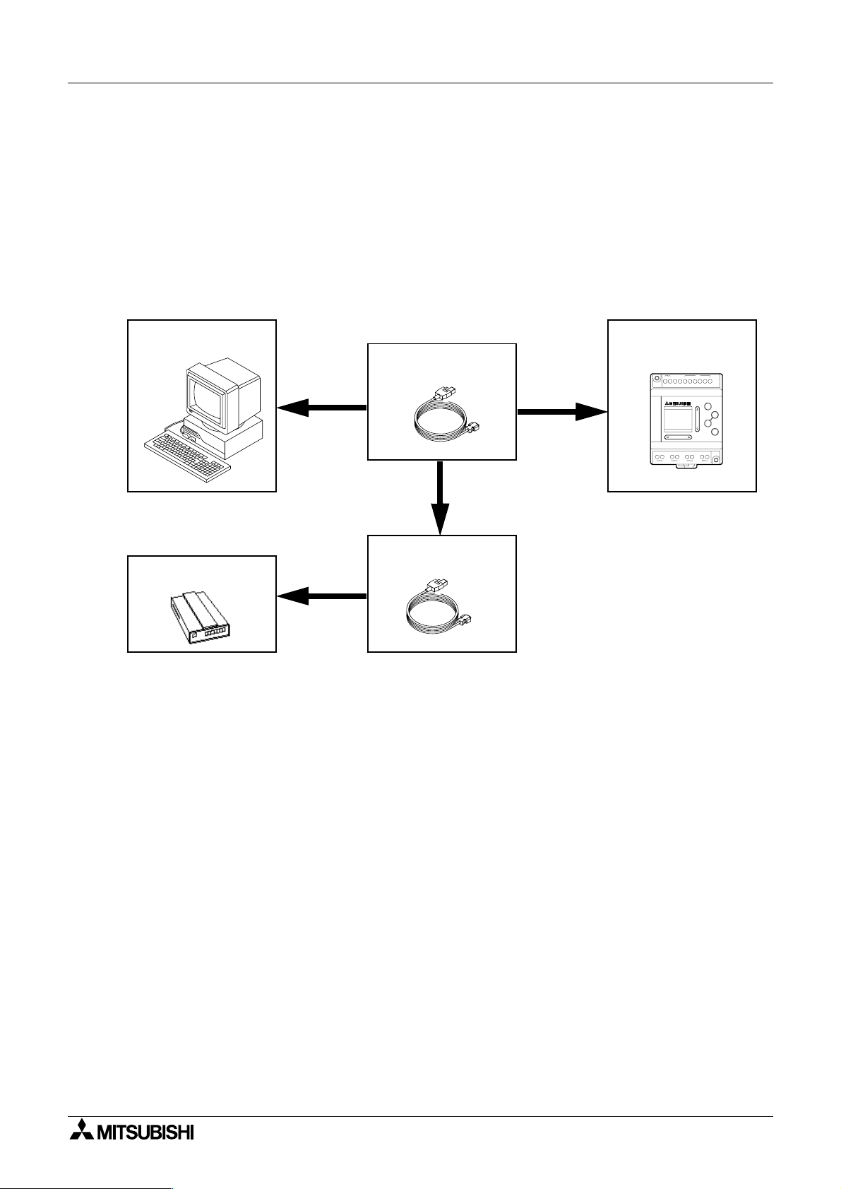
2.4 System Configuration
The system configuration for the Personal Computer and α controller is diagrammed below.
Please check for proper connections before transferrin
the PC. The Communications port for pro
α
the
controller can be designated in the COM pull down Menu in the VLS software.
ram transfer via Modem can also be accomplished; use the Initialize Controller Modem
Pro
Command in the Option Menu to confi
Installation 2
programs between the controller and
ram transfer between the personal computer and
ure the modem setup. See Chapter 6 for details.
Computer
Modem
AL-232CAB
RS-232Cable
Option
α
controller
POWER
AC 100/2 40V
RELAYOUTPUT
OUT1 OUT4OUT3OUT2
ACINPUT
IN
6NL 51234
ESC
+
-
OK
2-2
 Loading...