

Page 1

ISSUE 1. JUNE 1988
SMART-l
SMART-l CALL CONTROLLER
HARDWARE INSTALLATION
SECTION 8350-345012-NA
MANUAL1
@ Copyright 1988 MITEL INC. All rights reserved.
@ Registered Trademark of MITEL Corporation
PRINTED
IN CANADA
Page 2
SECTION 8350-345012-NA
ISSUE 1, JUNE 1988
MITEL FIELD SERVICE
MLTEL INC. has set up a National Field Service number for technical and installation
assistance (214) 241-4555 during normal working hours, for U.S. customers. Outside
normal working hours a telephone answering service has been established.
For Canadian customers contact the Canadian Regional Office (613) 592-0200 or the
National Field Service Number.
NOTICE TO CUSTOMERS
The information contained in this document is bheved
The htformation is subject to change without notice and should not be construed in any way as a commitment
INC. or any
any errors or
changes.
of
its affiliates and subsidiaries.
omissions in this document.
MITEL INC. and its affihates and subsidiaries assume no responstbility for
Revisions of this document or new editions of it may be issued to incorporate such
to be accurate in all respects but is not warranted by MITEL INC.
by
MITEL
WARNING
The Call Controller generates, uses and can radiate radio frequency energy and, if not installed.and used in accordance with
the instructions manual. may cause interference to radio communications. It has been tested and found to comply with the
limits
for a Class A computing device pursuant to Subpart J of
able protection against such interference when operated in a commercial environment. Operation of this equipment in a
residential area is likely to cause interference, in which case the user, at his own expense, will be required to
measures may be required to correct the interference.
NOTICE TO CANADIAN CUSTOMERS
The Canadian Department of Communications label identifies certified equipment. This certification means that the equipment meets certain telecommunications
guarantee the equipment will operate to the user’s satisfaction.
Before installing this equipment, users should ensure that it is permissible to be connected to the facilities of the local telecommunications company. The equipment must also be installed using acceptable method OC connection. In some cases,
the company’s inside wiring associated with a single line individual service may be extended by means of a certified connector assembly (telephone extension cord). The customer should be aware that compliance with the above conditions may not
prevent degradation of service in some situations.
Repairs to certified equipment should be made by an authorized Canadian maintenance facility designated by the supplier.
Any repairs or alterations made by the user to this equipment, or equipment malfunctions, may give the telecommunications
company cause to request the user to disconnect the equipment.
network
protective, operation$. and safety requirements. The department does not
Warning
Part IS of FCC
Rules, which are designed to provide reason-
take
whatever
Users should ensure, for their own protection, that the electrical ground protections to the power utility, telephone lines, and
internal metallic water pipe system; if present, are connected together.
Caution
Users
should not attempt to make such connections themselves, but should contact the appropriate electric inspection author-
ity, or electrician, as required.
The Load Number (LN) assigned to each terminal device denotes the percentage of the total load, to be connected to a
telephone loo?, that is used by the device to prevent overloading. The termination on a loop may consist of any combination
of devices SubJect only to the requirement that the total of Load Numbers of all the devices subject does not exceed 100. An
alphabetic suffii is also specified in the Load Number and designates the appropriate ringing type (A or B), if applicable.
For example, LN = 20 A designates a load number
PAV
of
20 and an ‘A’ type ringer.
PAGE 1.1
Page 3

ISSUE 1, JUNE 1988
SECTION 8350-345-012-NA
HEADING
1. INTRODUCTION
1. 1. General
1. 2. Programming Devices
l.3.PositiveAccountCodeVerification
1. 4. Chaining
2. BASIC HARDWARE INSTALLATION
2. 1. DESCRIPTION
2. 1. I. Mechanical Description
2. 1. 2. Electrical Description
2. 2. General Mounting
2. 3. Wall Mounting Bracket
2. 4. Ground
2. 5. Telephone Connections
. . . . . . . . . . . . . . . . . . . . . . . . . . . . . . . . . . . . . . . . . . . . . . . . . . . . . . . ..~
..........................................................
..................................................
.......................................................
............................................
.................................................................
....................................
... .
............................................................
...................................................
.....................................................
..........
.....................................................
..................................................................
. ..............................................
.....................................................
2. 6.InstallatiosaOfARecordingUnitQrProgrammingTerminal
2. 7. Powering Up
2. 8. Power Failure
2. 9. Ground Start Installation Testing
3. INITIALIZATION
..........................................
.............................................................
..............................................
.,...............,....................... . . . . . . . . . . . . . . . . . 1.15
.......................
. ...........
. ...............
._ ................
PAGE
1.3
1.3
1.4
1.5
1.6
1.7
1.7
1.7
1.7
1.8
1.9
1.9
1.10
1.12
1.13
1.13
1.14
3. 1. Initialization From A DTMF Telephone
3. 2. Effects Of Initialization
3.3. WakingUptheController..
APPENDIX 1
................................................................
HARDWARE SPECIFICATIONS
ORDERING INFORMATION
.....................................................
..... mP,.
.................................................
0.00.00.**90a*00.0..a...............
........................................
........................................
PAVCall Controller ............................................................
PAV Chaining Call Controller
Other Components
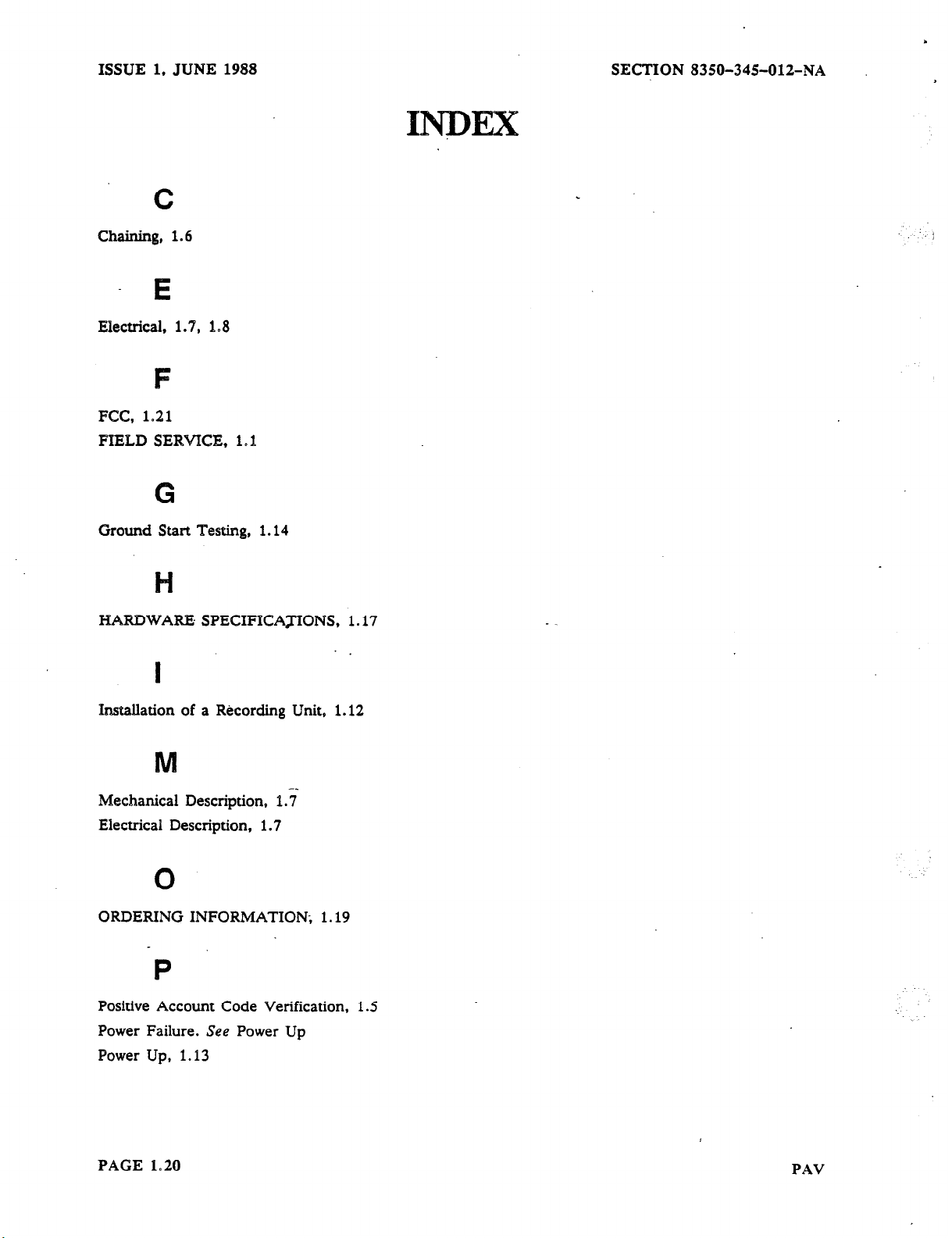
INDEX
. . . . . . . . . . . . . . . . . . . . . . . . . . . . . . . . . . . . . . . . . . . . . . . . . .
..............................................................
FCC INTERCONNECTION REQUIREMENTS
......................................................
. . . . . . . . . . . . . . . . . . . . . . . . . . . . . .
..D...*.*OODD. 1.19
. . . . . . . ..*..........
. . . . . .
1.15
1.16
1.16
1.17
1.17
1.19
1.19
1.19
1.20
1.21
PAGE 1.2
PAV
Page 4
SECTION 8350-345012-NA
ISSUE 1, JUNE 1988
_
1, INTROlXJCTION
1. 1. General
The SMART- 1 Telephone Controller is a simple, compact and versatile telephone controller providing:
Versatile Programming
Four, or two line, or one line capacity
Automatic Route Selection (ARS)
Speed Call capacity of either 100, or 1000
Handles Loop Start Or Ground Start Telephone Lines
Off-Hook Redial
Remote Maintenance And Programming
Compatible With Rotary Or DTMP Telephones and Telephone Offices
Battery Back-up Of Customer’s Memory
Separate Program Access Code To Allow Customer Speed Call Update/Maintenance
Progress Tones Available For Call And Route Progress
Programmable For Account Code Change On Route Change
Compliance with FCC Parts 68 and 15
Separate program entry to allow customer update and maintenance of PAV lists
Progress tones programmable on a route by route basis
Useable with Centrex Lines
Useable behind a PBX/PABX
Hot Line operation
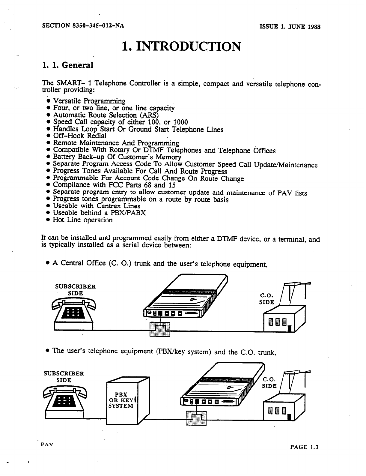
It can be installed and programmed easily from either a DTMP device, or a terminal, and
is typically installed as a serial device between:
l
A Central Office
SUBSCRIBER
SIDE
l
The user’s telephone equipment (PBX/key system) and the C.O. trunk,
(C. 0.) trunk and the user’s telephone equipment,
n
PAV
PAGE 1.3
Page 5
ISSUE 1, JUNE 1988
l
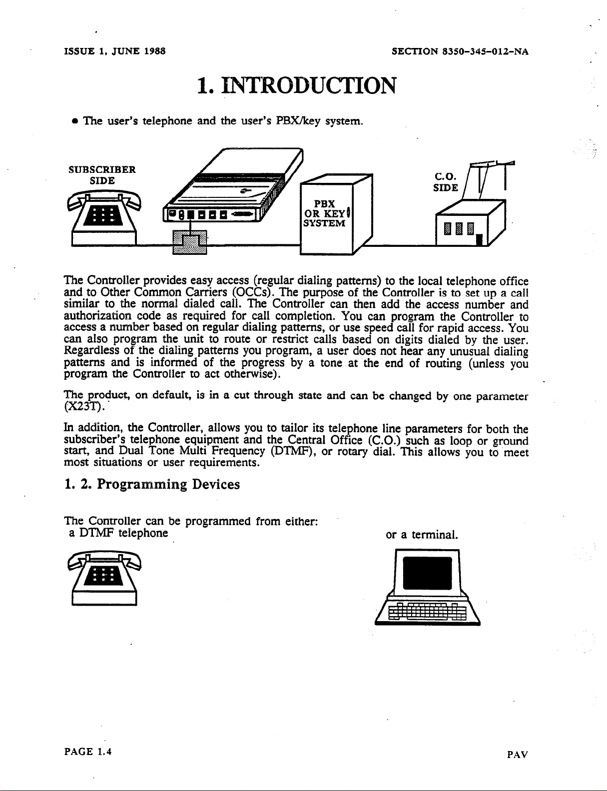
The user’s telephone and
SUBSCRIBER
SIDE
1
0
INTRODUCTION
the user’s PBXkey system.
SECTION 8350-34%012-NA
The Controller provides easy access (regular dialing patterns) to the local telephone office
and to Other Common Carriers (OCCs). The purpose of the Controller is to set up a call
similar to the normal dialed call. The Controller can then add the access number and
authorizatiow code as required for call completion. You can program the Controller to
access a number based on regular dialing patterns, or use speed call for rapid access. You
can also program the unit to route or restrict calls based on digits dialed by the user.
Regardless of the dialing patterns you program, a user does not hear any unusual dialing
patterns and is informed of the progress by a tone at the end of routing (unless you
program the Controller to act otherwise).
. . .
The product, on .default, is in a cut through state and can be changed by one parameter
(x23T).
.
In addition, the Controller, allows you to tailor its telephone line parameters for both the
subscriber’s telephone equipment and the Central Office (C.O.) such as loop or ground
start, and Dual Tone Multi Frequency (DTMF), or rotary dial. This allows you to meet
most situations or user requirements.
1.
2, Programming Devices
The Controller can be programmed from either:
a DTMF telephone
or a terminal.
PAGE 1.4
PAV
Page 6
SECTION
8350-345012-NA
ISSUE
1,
JUNE
1988
1. INTRODUCTION
1. 3. Positive Account Code Verification
The Controller can be programmed to require an Account Code before allowing a call.
These Account Codes can be assigned to each individual person using the telephone lines
connected to the Controller. These Account Codes can vary according to the route used as
selected by the Controller. In addition, the Account Codes will appear on any Call Detail
Records (CDR) output by the Controller through its RS-232 port. These records are valuable when determining billing information, call cost analysis or traffic patterns.
If you wish to assign Account Codes that can be verified to persons using the the tele-
phone lines connected’to the Contrcller, you will want to configure the unit as a Control-
ler with Positive Account Code Verification (PAV). For call screening/toll control purposes this will limit
ike Verifiable Account Codes.
you
to one set of tables (Primary). The Alternate tables are used for
_.
Should you not require Positive Account Code Verification you should configure the
as a Controller without PAV.
For more information on the PAV Controller see POSlTMZ
‘I-IONS in MANUAL 2.
ACCOUNT
.
CODE
unit
OP-
PAV
PAGE 1.5
Page 7
ISSUE 1,
JUNE 1988
1. 4. Chaining
SECTION 835&I-345-012-NA
1. INTRODU~ON’
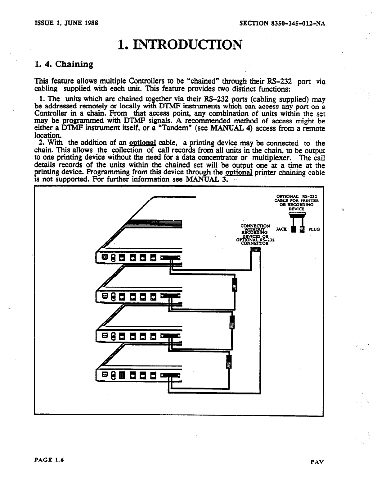
This feature allows multiple Controllers to be “chained” through their M-232
port via
cabling supplied with each unit This feature provides two distinct functions:
1. The units which are chained together via their IS-232 ports (cabhng supplied) may
be addressed remotely or %ocally with DTMF instruments which can access any port om a
Controller in a chain. From that access point, any combination of units within the set
may be programmed with DTMF signals. A recommended method of access might be
either a DTMF instrument itself, or a “Tandem” (see MANUAL 4) access from a remote
location.
2. With the
addition of an outionai cable, a printing device may be connected to the
chain. This allows the collection of call records from all units in the chain, to be output
to one printing device without the need for a data concentrator or multiplexer.
The call
details records of the units within the chained set will be output one at a time at the
printing .device. Programming from this device through the gwtional printer chaining cable
is not supported. For further information see MANUAL 3. ‘.
QmTONAL Rs-532
CABLE FOR PRIMTER
OR RRCORD6NG
JACX
2
PLUG
PAGE 1.6
PAV
Page 8

SECTION
8350-34%OlZ-NA
BASIC HARDWARE INSTALLATION
2
l
2. 1. DESCRIPTION
2. 1. 1. Mechanical Description
ISSUE 1, JUNE 1988
The Controller (Figure 1.1 ) consists of a plastic case, enclosed circuitry and an outboard
.*-.
power supply.
. .
2. 1. 2. Electrical Description
Controller electrical characteristics are provided in Figure 1.1
POWER SUPPLY
.
DIMENSIONS: 1.38 x 7.63 x 10.6 inches
MOUNTING:
Flush or Right Angle Wall
Mount, Table Top
Note: The above illustration and the rest of this manual
line unit. Your unit may be: one, two or four lines. In the
CONNECTIONS: Standard RJ3 1X
shows the Controller as a four
programming and installatjon
you should disregard programming for lines that you do not
PAV
With one FemaleRS-232
and Connector for
have.
PAGE 1.7
Page 9

ISSUE 1, JUNE 1988 SECTION 8350~34501%NA
2, BASIC lE!IMtDWARE INSTAlYLA~ON
2. 2. General Mounting
Since you are reading this part of the Installation Section, it is assumed that you have
unpacked the Controller. At this point, you are ready to proceed with the installation.
Before proceeding ensure you have:
oA place to mount the Controller right side up (Figure 1.2 ), on a suitable backboard
(Figure 1.3 ).
o A screwdriver and wrench or pliers for the mounting hardware.
@ Access to power, a ground, and telephone lines for the Controller (connected to RI31
blocks).
You must provide a single phase power receptacle with the following recommendations:
@ 103.5 - 126.5 VAC, 60 Hz fused and capable of delivering 350 mA per unit installed.
QJ The power receptacle should be wired and fused independently from all other recepta-
cles that are not controller related.
A warning tag should be attached to circuit breaker type fuses to prevent unauthorized
manual operations.
.
@ The power receptacle should not be controlled by a switch.
@ The live and neutral conductors at the receptacle should be
respective connections.
@ The power receptacle must be a 3-wire type, with the ground
wired to their proper
.
wire connected. to the.
ground of the electrical system.
@ The receptacle location should be selected to prevent accidental removal of the power
cord.
@ The receptacle should be easily accessible for the removal of the plug for mainte-
nance.
Syfficient space around the units, especially the. cable side, should be left for cabling.
This 1s very important if you intend to use chaining. You should also mark all cables as
to
their identity as this will ease troubleshooting problems..
Plgure I.2 Mounting Position
PAGE 1.8
THIS WAY
NOT
THT,C WAY
PAV
Page 10
SECTION 8350-345-012-NA
ISSUE 1, JUNE 1988
2. BASIC HARDWARE INSTALLATION
For information on installing chaining see MANUAL 3.
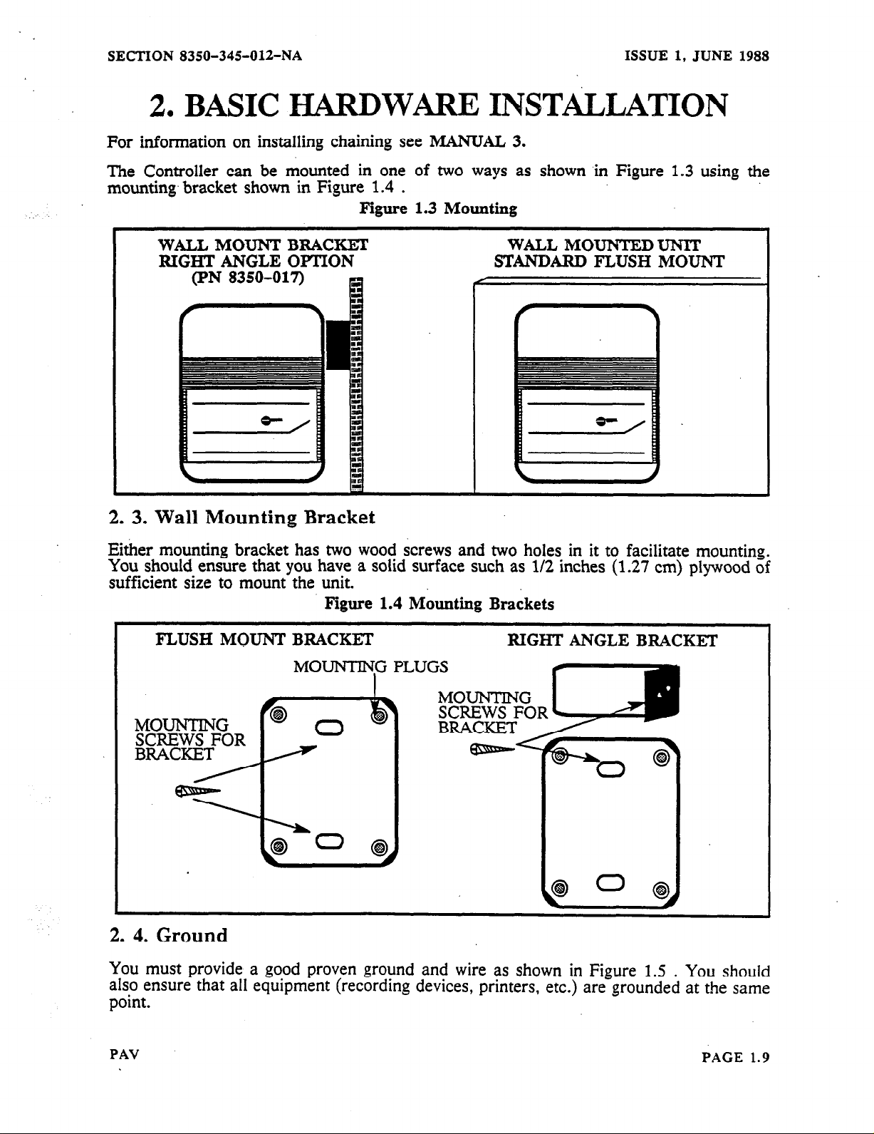
The Controller can be mounted in one of two ways as shown in Figure 1.3 using the
mounting. bracket shown in Figure 1.4 .
Figure 1.3
Mounting
WALL MOUNT BRACKET
RIGHT ANGLE OPTION
(PN 8350-017) R
WALL MOUNTEDUNIT
STANDARD FLUSH MOUNT
2. 3. Wall Mounting Bracket
Either mounting bracket has two wood screws and two holes in it to facilitate mounting.
You should ensure that you have a solid surface such as l/2 inches (1.27 cm) plywood of
sufficient size to mount the unit.
Figure 1.4
FLUSH MOUNT BRACKET
Mounting
Brackets
RIGHT ANGLE BRACKET
MOUNTING PLUGS
MOUNTING
SCREWS FOR
BRACKET
2. 4. Ground
You must provide a good proven ground and wire as shown in Figure 1.5 . You should
also ensure that all equipment (recording devices, printers, etc.) are grounded at the same
point.
PAV
PAGE 1.9
Page 11

ISSUE 1, JUNE 1988
2.
BASIC HARDWARE INSTALLATION
SECTION 8350-345012-NA
Figure
1.5 Ground Wisisg
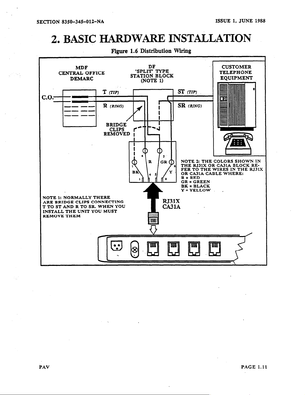
2. 5. Telephone Connections
The telephone connections should be made at the distribution block on your side of the
telephone protection units, following established procedures and techniques (Figure 1.6 ).
Tylxcally, vhen you connect to the modular jacks in your building you will be on the
protected sfde of the telephone connections (if you are not sure, you should check).
Fngure 1.6 illustrates the USOC RJ3lX Connector and cable assembly as used by the
Controller. The FIGURE also illustrates a typical distribution block set up. Note: the
cemter bridging clips are not inserted on the station block. This means that the Controller
acts as a connector between the left and right connection points on the Station Block in
Figure 1.6
If you wire the Controller per Figure 1.6 it will when programmed, physically route calls
through it, to the C.O.. This is done transnarentlv to the user, but all digits (whether
DTI@ or rotary) dialed by the user can be &zreened and
the user from the line when the user goes
D
routed. This is done by splitting
off-hook.
co.
SIDE
Once enough digits have been screened, the Controller decides the routing and dialing
patterns. Then the Controller outputs the proper dialing sequence to the CO..
SUBSCRIBER
.
Once the digits have been sent to the C.O. the caller will be connected to the C.O..
PAGE
1.10
PAV
Page 12
SECTION 8350-34%012-NA
2.
BASIC HARDWARE INSTmLATION
Figure 1.6 Distribution Wtig
ISSUE 1, JUNE
1988
MDF
CENTRAL OFFICE
DEMARC
T
(TIP)
NOTE 1: NORMALLY THERE
ARE BRIDGE CLIPS CONNECTING
T TO ST AND R TO SR. WHEN YOU
INSTALL THE UNIT YOU MUST
REMOVE THEM
’
SPL&YPE
STATION BLOCK
(N&E
1)
CUSTOMER
TELEPHONE
EQUIPMENT
= (TIP)
NOTE 2: THE COLORS SHOWN IN
THE RJ3lX OR CA3lA BLOCK REFER TO THE WIRES IN THE RJ31X
OR CA31A CABLE WHERE:
R=RED
CR = GREEN
BK = BLACK
Y =YELLOW ,
PAV
PAGE.
1.11
Page 13
ISSUE 1. JUNE 1988
SECTION 8350-34%01%NA
2, BASIC HARDWiiItE INSTALLATION
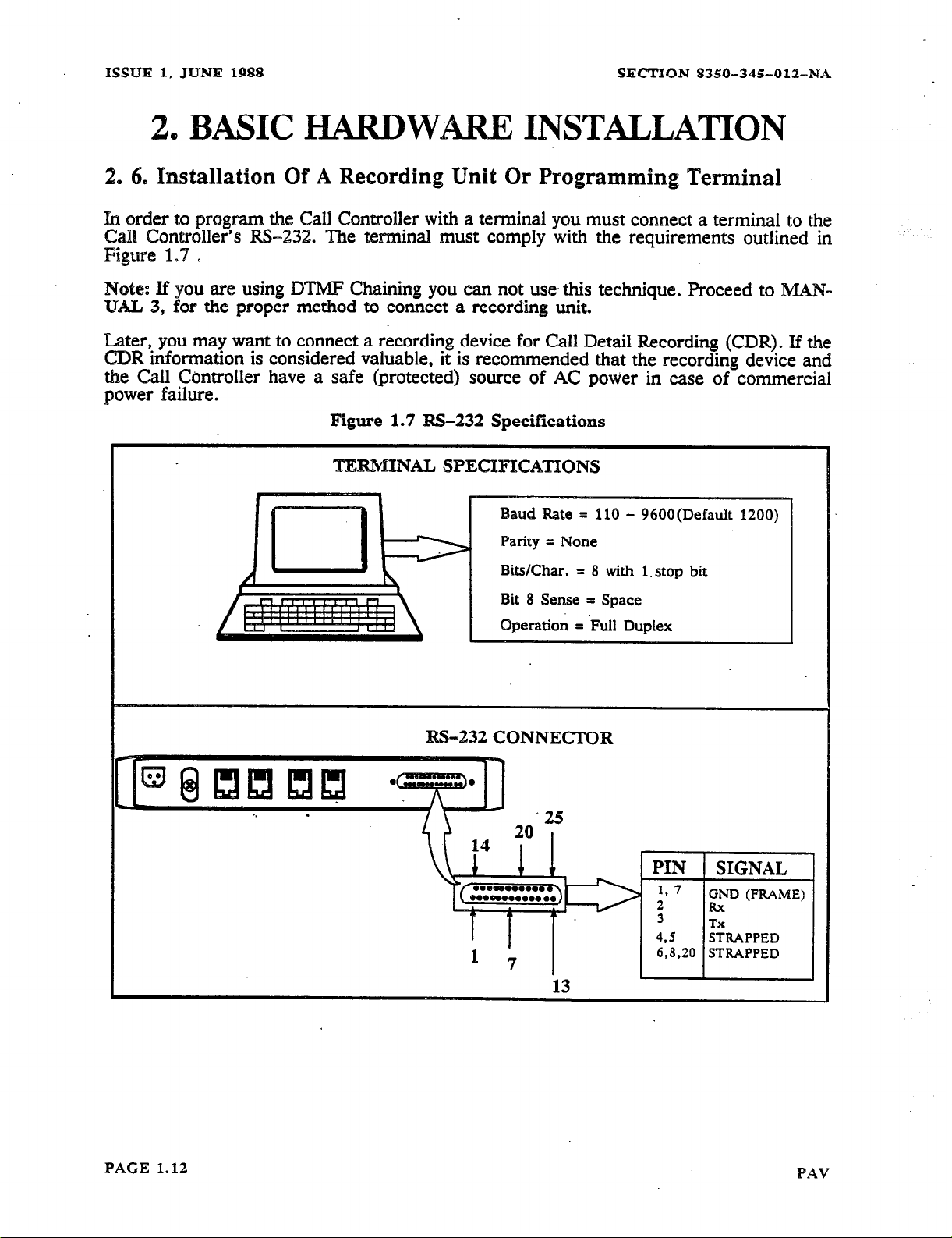
2. 6. Installation Of A Resording Unit Or Programning Terminal
h
order to program the Call Controller with a terminal you must connect 8 termiflal to the
Call Controller’s RS-232. The terminal must comply with the requirements outlined in
Figure 1.7 D
Note: If you are using DTMF Chaining you can not
use.
this
technique. Proceed to IMAW
lL4.L 3, for the proper method to connect a recording unit.
Later, you may want to connect a recording device for Call Detail Recording (CDR). If the
CDR information is considered valuable, it is recommended that the recording device and
the Call Controller have a safe (protected) source of AC power in case of commercial
power failure.
Figure 1.7 RS-232 Specifications
TERMINAL SPECIHCA’XTONS
= 8 with
Bit 8 Sense = Space
W-232 CONNECTOR
l-stop bit
PAGE 1.12
PAV
Page 14
SECTION 8350-345012-NA
BASIC HARDWARE INSTALLATION
2
l
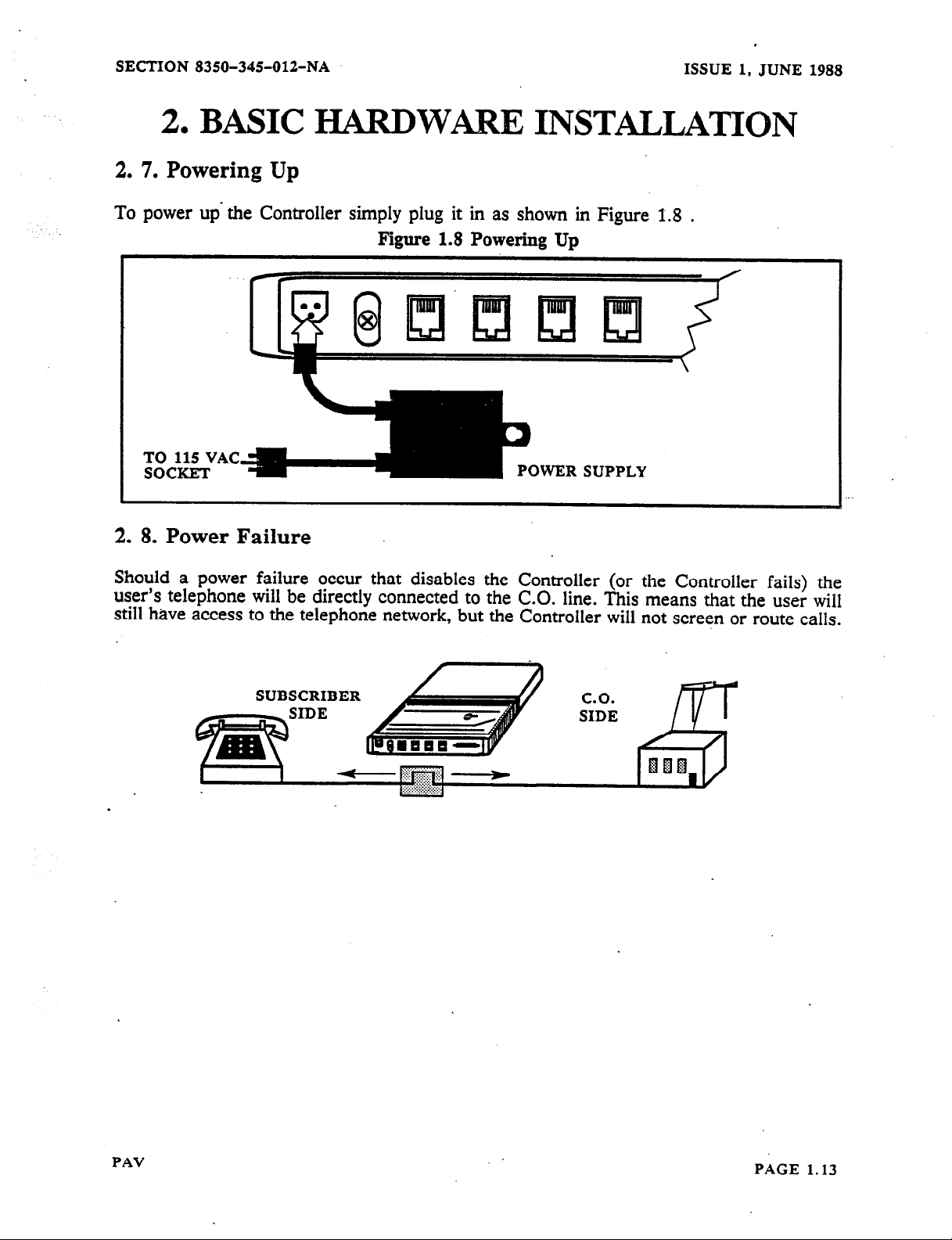
2. 7. Powering Up
ISSUE 1, JUNE 1988
To power up’ the Controller simply plug it in as shown in Figure I.8
.
Figure 1.8 Powering Up
TO 115 VAC
SOCKET
POWER SUPPLY
2. 8. Power Failure
Should a power failure occur that disables the Controller (or the Controller fails) the
user’s telephone will be directly connected to the CO. line. This means that the user will
still have access to the telephone network, but the Controller will not screen or route calls.
SUBSCRIBER
C.O.
SIDE
PAV
PAGE 1.13
Page 15
ISSUE
1.
J?JNE 1988
2,
BASIC lilAlXDW= INSTALIATION
SECTION 8350-345-012-NA
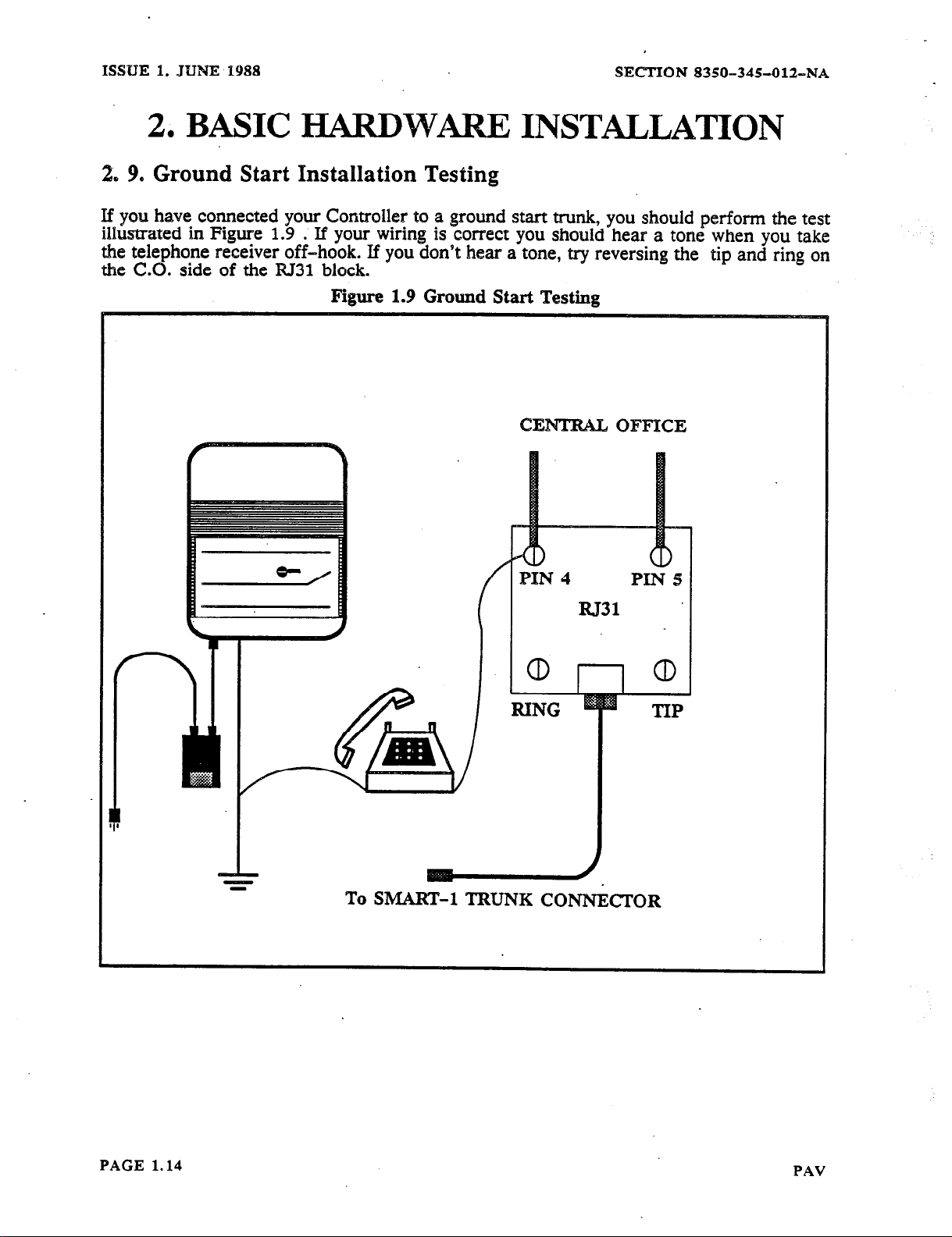
2. 9. Ground Start Installation Testing
If you have connected your Controller to a ground start trunk, you should perform the test
illustrated in Figure 1.9 S If your wiring is correct you should hear a tone when you take
the telephone receiver off-hook. If you don’t hear a tone, try reversing the tip and ring on
the C.0. side of the RJ31 block.
Figure 1.9 Ground Start Testing
PAGE 1.14
1_
To
SMART-1
TRUNK CONN&TOR
PAV
Page 16
SECTION 8350-345-01%NA
ISSUE 1, JUNE 1988
3. INITIALIZATION
Before performing any further installation you should power the controller(s) up for 24 hours to
allow the back-up batteries to charge filly.
:
In~i~~~z
be a
program the Con?oiler the first time or YOU wish to reset the Controller to its
ueq you
must inmallze the unit. This can be done from a DTMF telephone
only.
3. 1. Initialization From A DTMF Telephone
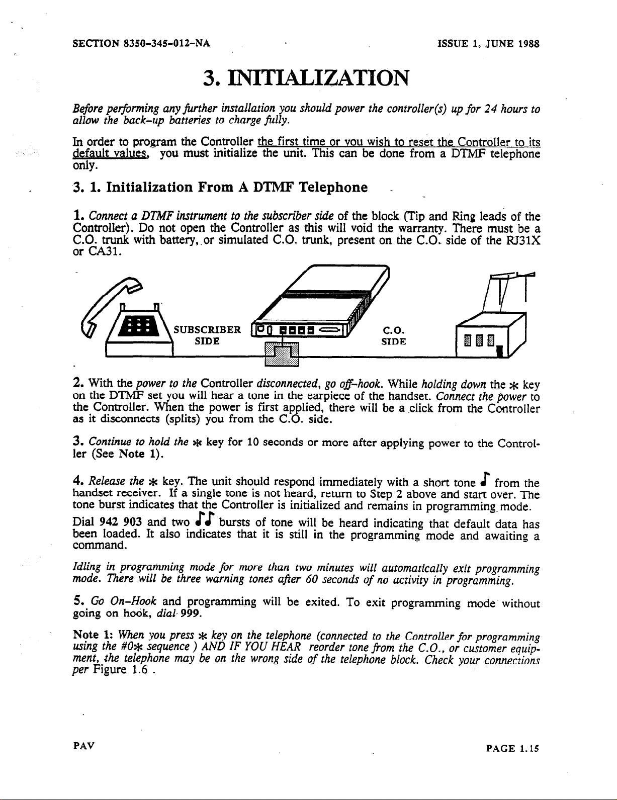
1.
Connect a DTMF instrument to the subscriber side
Controller). Do not open the Controller as this will void the w&anty. ,Th&e
zrtAy with battery, .or simulated C.O. trunk, present on the C.O. side of
.
SUBSCRIBER
2.
With the
power to the
Controller
disconnected, go o&hook.
on the DTMF set you will hear a tone in the earpiece of the handset.
the Controller. When the power is first applied, there will be a click from the Controller
as it disconnects (splits) you from the C.O. side.
of the block (Tin and Ring leads of the
must be a
the RJ31X
n
While
holding down
Connect the ljower
the * key
to
3.
Continue to hold the *
ler (See
4.
Release the *
Note 1).
key. The unit should respond immediately with a short tone E from the
key for 10 seconds or more after applying power to the Control-
handset receiver. If a single tone is not heard, return to Step 2 above and start over. The
tone burst indicates that the Controller is initialized and remains in programming. mode.
Dial 942 903 and two EE
bursts of tone will be heard indicating that default data has
&zf;$ed. It also indicates that it is still in the programming mode and awaiting a
.
Idling in programming mode for more than two minutes will automatically exit programming
mode. There will be three warning tones after 60 seconds of no activity in programming.
5. Go On-Hook
going on hook,
Note 1:
ustng the #O* sequence ) AND IF YOU HEAR reorder tone from the C.O., or customer equipment, the telephone may be on the wrong side of the telephone block. Check your connections
per
When you press * key on the telephone (connected to the Controller for programming
Figure 1.6
and programming will be exited. To exit programming mode’ without
dial 999.
.
PAV
PAGE 1.15
Page 17
ISSUE 1, JUNE 1988
SECTION 8350-345012-NA
3. INITIALIZATION
3. 2. Effects Of Initialization
When you have initialized the Controller all dialing will be passed straight through it, to
the CC.. The Controller will not attempt to analyze, route or screen calls.
3. 3.
After initializing, you must wakeup the Controller. You murt be in programming mode to
w&-up the Controller. If you are not in programmin
from a terminal a <CR> to enter programming mode. Waking up the Controller for all
,trunks (while in programming), can be done by dialing 5238. This causes the Controller
to:
Waking Up the Controller
g mode you should enter # 0
will be heard by the user, when the user makes a call.
E
*A
o Only respond to the programming command of # 0 % from a DTMF telephone or a
carriage return (<CR>) from a terminal.
e Set all trunks to loop start, DTMF
8 Route all no-n 1 + (local) calls go via DDD
@ Route all 911, f-411, l-555, l-area code-555, l-800 calls go via DDD
Q Route all other l+ (long distance) calls go via CCC
e Route all local calls after the first digit is dialed
e Route all l+ calls after fourth digit dialed.
* ,
or
FOR ADDITIONAL PROGRAMM@=G
LvPROCEED TO ikXANUAL 2~
PAGE 1.16
FOR C-G INSTALLATION AND
PROGRAMMING
ePROCEED TO MANUAL 3-a
PAV
Page 18
SECTION 8350-345-012-NA
ISSUE 1, JUNE 1988
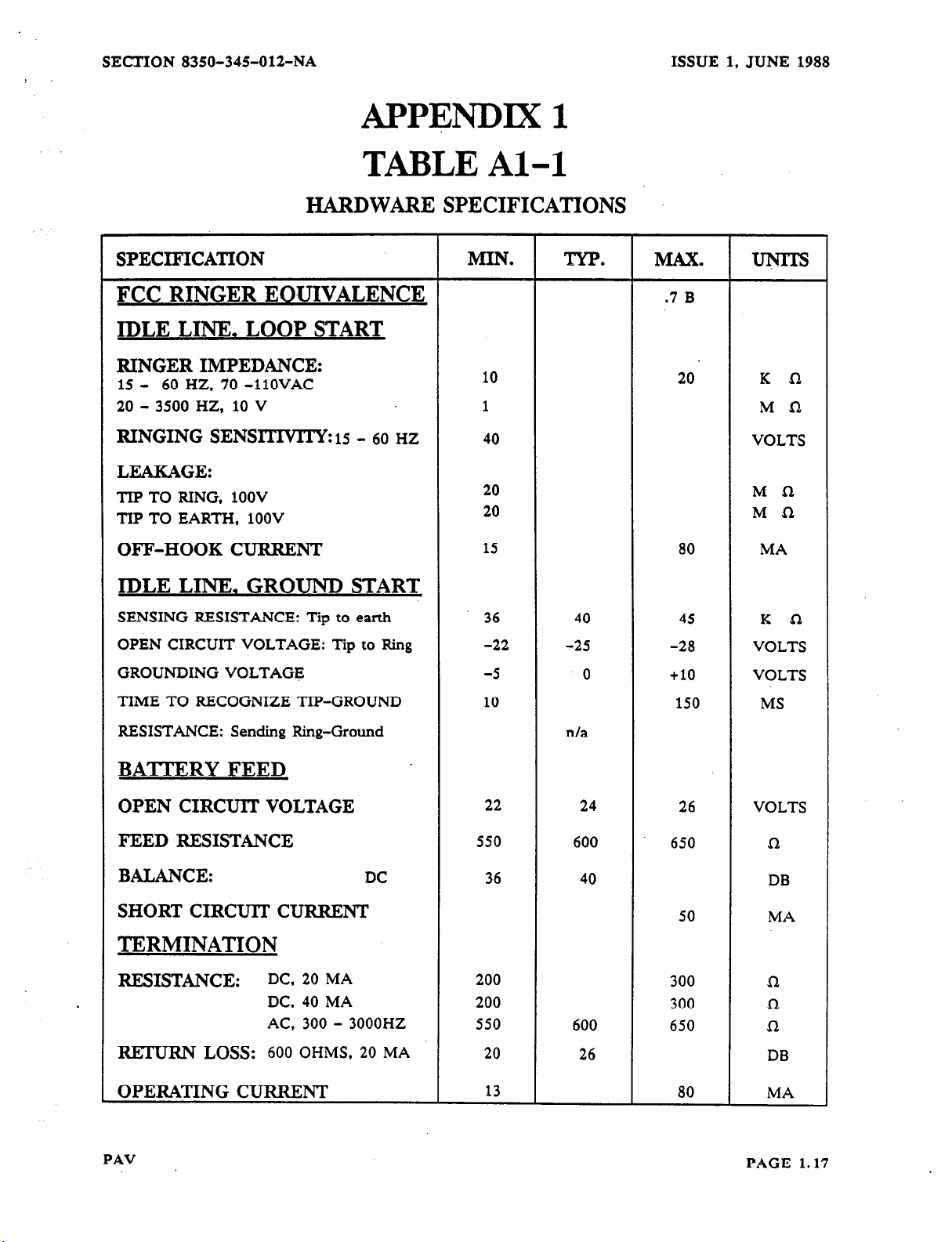
APPENDIX 1
TABLE Al-l
HARDWARE SPECIFICATIONS
SPECIFICATION
FCC RINGER EOUIVALENCE
IDLE LINE. LOOP START
RINGER IMPEDANCE:
15 - 60 HZ, 70 -1lOVAC
20 - 3500 HZ, 10 V
RINGING SENS~TWITYZI~ - 60 HZ
LEAKAGE:
TIP TO RING, 1OOV
TIP TO EARTH, 1OOV
OFF-HOOK CURRENT
IDLE LINE. GROUND START
SENSING RESISTANCE: Tip to earth
OPBN CIRCUIT VOLTAGE: to
GROUNDING VOLTAGE
TIME TO RECOGNIZE TIP-GROUND
Tip Ring
MIN. TYP. MAX. UNITS
.7
B
10
1
40
20
20
15
36 40
-22 -25
-5
10
0 +lO VOLTS
20 K n
MQ
VOLTS
Ma
Ma
80 MA
45 K n
-28 VOLTS
150 MS
RESISTANCE: Sending Ring-Ground
BATTERY FEED
OPEN CIRCUIT VOLTAGE
FEED RESISTANCE
BALANCE:
DC
SHORT CIRCUIT CURRENT
TERMINATION
RESISTANCE:
mm Loss: 600 OHMS, 20 MA
OPERATING CURRENT
PAV
DC, 20 MA
DC, 40 MA 200
AC, 300 - 3000HZ 550 600
n/a
22
550 600
36
200
20
13
24 26 VOLTS
40
26 DB
650 n
DB
50
300 sz
300 n
650 R
80 MA
MA
PAGE 1.17
Page 19
ISSUE 1, JUNE 1988
SECTION 8350-345-012-NA
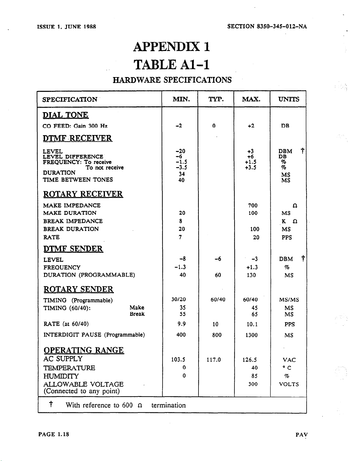
APPENDIX 1
TBLE Al-l
I-XARDWmE
DIAL TONE
CO FEED: Gain 300 Hz
DTMF .RECElVER
LEVEL
LEVEL DIFFERENCE
FREQUENCY: To receive
DURATION
TIME BETWEEN TONES
ROTARY RECEIVElR
M&E
MAKE DURATION
BREAK
BREAK DURATION
RATE
IMPEDANCE
IMPEDANCE
To not receive
SPECIFICATIONS
20
7
100
20
‘MS
PPS
DTMF SENDER
LEVEL -8 -6 -3 DBM j
FREQUENCY
DUIWTION (PROGRAMMABLE) 40 60 130 MS
-1.3
+1.3
%
ROTARY SENDER
TIMING (Programmable)
TIMING (60/40): Make
Break
RATE (at 60/40)
INTERDIGIT PAUSE (Programmable)
30120 60140 60140 MS/MS
35 45 MS
5s 65 MS
9.9 10 10.1 PPS
400 800 1300 MS
OPERATING RANGE
Ac
SUPPLY
TIZMPERAW
mw
ALLOWABLE VOLTAGE
(Connected to any point)
With reference to 600 CI termination
103.5 117.0 126.5 VAC
0 40 “C
0 85 %
300 VOLTS
PAGE 1.18
PAV
Page 20
SECTION
8350-345-012-NA
ISSUE
1,
JUNE
1988
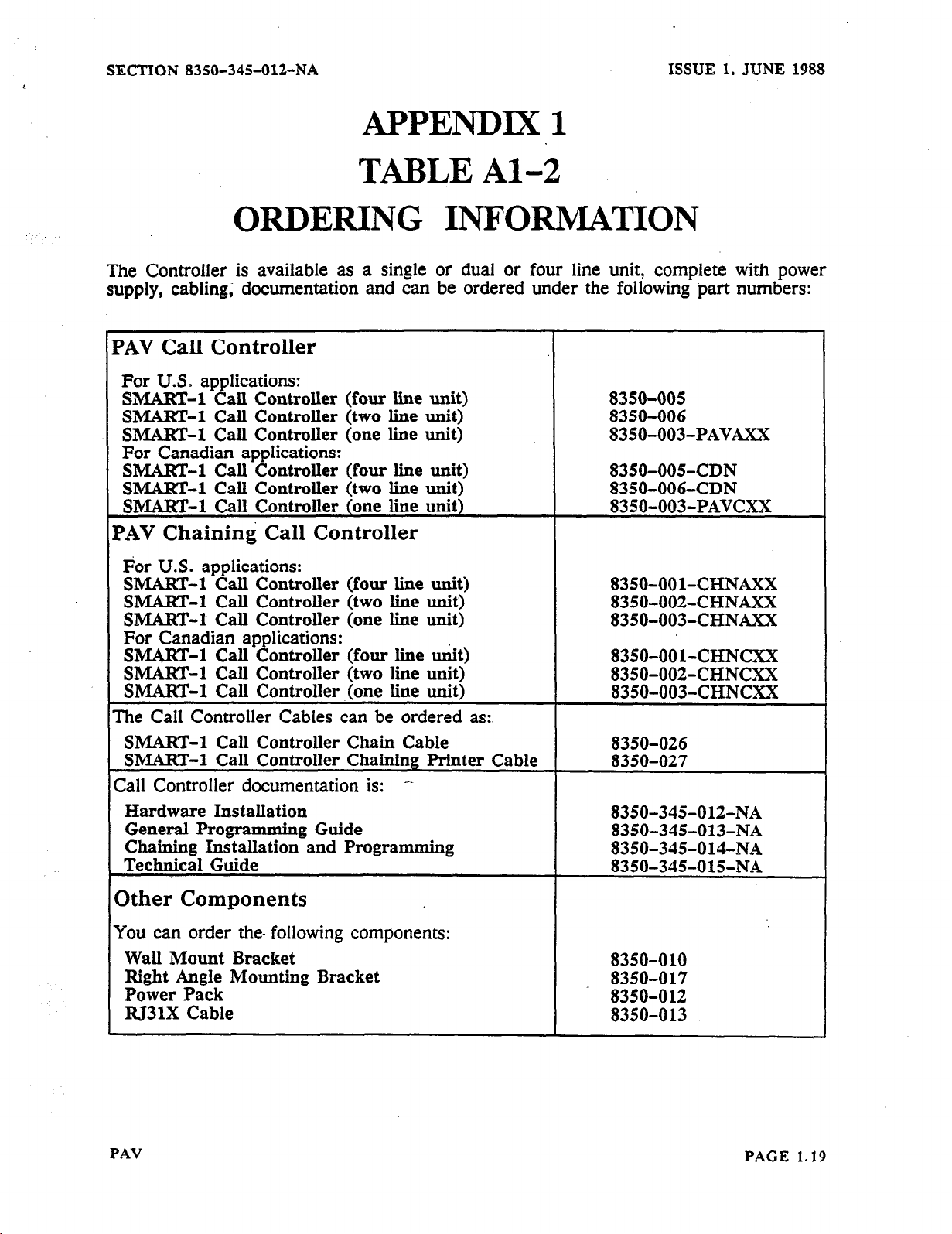
APPENDIX 1
TABLE Al-2
ORDERING INFORMATION
The Controller is available as a single or dual or four line unit, complete with power
supply, cabling; documentation and can be ordered under the following part numbers:
PAV
PAV
The Call Controller Cables can be ordered as:.
Call Controller documentation is: -_
Call Controller
For U.S. applications:
SMART-1 Call Controller (four line unit)
SMART-l Call Controller (two line unit)
SMART-l Call Controller (one line unit)
For Canadian applications:
SMART-1 Call Controller (four line unit)
SMART-l Call Controller (two line unit)
SMART-l Call Controller (one line unit)
Chaining Call Controller
For U.S. applications:
SMART-l Call Controller (four line unit)
SMART-l Call Controller (two line unit)
SMART-l Call Controller (one line unit)
For Canadian applications:
SMART-l Call Controller (four line unit)
SMART-l Call Controller (two line unit)
SMART-l Call Controller .(one line unit)
SMART-l Call Controller Chain Cable
SMART-l Call Controller Chaining Printer Cable
Hardware Installation
General Programming Guide
Chaining Installation and Programming
Technical Guide
8350-005
8350-006
8350-003-PAVAXX
8350-005-CDN
8350-006-CDN
8350-003-PAVCXX
8350-OOl-CHNAXX
8350-002-CHNAXX
8350-003-CHNAXX
8350-OOl-CHNCXX
8350-002-CHNCXX
8350-003-CHNCXX
8350-026
8350-027
8350-345-012-NA
8350-345-013-NA
8350-345-014-NA
8350-345-o 15-NA
Other Components
You can order the- following components:
Wall Mount Bracket
Right Angle Mounting Bracket
Power Pack
RJ31X Cable
PAV
8350-010
8350-017
8350-O 12
8350-013
PAGE
1.19
Page 21
ISSUE 1, JUNE 1988
C
Chaining, 1.6
SECTION 8350-34%012-NA
>
Electrical,
FCC,
HEED SERVICE, 1.1
Ground Start Testing, 1.14
1.21
1.7,
1.8
H
HARDWARE SPECIFICATIONS, 1.17
I
Installation of a Recording Unit, 1.12
Mechanical Description. 1.7
Electrical Description, 1.7
0
ORDERING INFORMATION; 1.19
Positive Account Code Verification, 1.5
Power Failure. See Power Up
Power Up, 1.13
PAGE 1.20
PAV
Page 22
SECTION 8350-345012-NA
ISSUE
1, JUNE 1988
FCC
This asuipmant hu been approved by the Federal Communications Cornmiss’
network when
section is applicable to telephone intersottnection in the United States.
Prior to interconnection of this equipment. the local teiephotte company is to be notif3edt Inform tits company that you have
FCC-registered equipment that you wish to Connect to their trunks. Give them the
l
The
l
The
l
The FCC registration number for the SMART - 1 Call Controller is EMP
l
The FCC Ringer
l
The connector jacks are BJ31X.
connected directly to the telephone lines through the standard connection cabling provided with the unit. This
telephone number of the line
equipment
INTERCONNECFION
that you will
number being
Equivalence Number (BEN) is 0.7B,
connected is
connect the unit
a MITEL INC. model SMART - 1 Call Controller,
REQUIREMEmS
ton (FCC) es not being harmful to the telephone
foIlowing information:
to,
46K-72059-L&E.
CONNECTION LXMITATIONS
Due to the
to be used on standard-device telephone lines. If there are any questions about the telephone line, such as how many pieces
of equipment may be connected to it, the telephone company will provide this information upon
FCC Part
68 Rule,
no
connection can be made to party lines and to coin telephone service. This unit is designed
request.
NETWORK CHANGES
The telephone company may make changes to its communication service: such changes may include the change
circuits,
official notification. so that the operation of the Call Controller service will not be interrupted.
changes in
opwatiod
characteristics of its trunks, etc. Before doing this, however, the company shall provide
MAINTENANCE LIMITATIONS
of
tNI&
This equipment has been registered with the FCC for direct connection to the telephonu network. Under the FCC program,
the user is restricted from making any changes or repairs and from performing any maintenance operations other than those
specifically included in this document.
There are no
No cabiing or wiring changes within the unit are permitted by the
to be used
Power supply components and cabling are only to be changed or maintained by MITEL INC. or by an authorized agent of
MITEL INC.
user
repairable parts within the unit. It is sealed against user maintenance. If opened ail warranties are voided.
user.
Plug-ended cables,
for all external connections between the unit and the unit and the telephone interface jack.
as
detailed in this
document, are
TROUBLE CORRECTIONS
For all malfunctions. appropriate field service is provided by MITEL INC. or its authorized agents.
DISCONNECTION
If ever
it is decided to
telephone company of this change
permanently disconnect the SMART -
1 Gail Controller from
the present line. please notify the
PAV
PAGE 1.21
Page 23

. . . . . . .._ _ __-..
;-,-.
ISSUE 2,
AUGUST 1988
SECTION 8350-~3%S-O13-F&%~
SMART-1
SMAJXT-1 CALL CONTROLLER
,..:.
,
MAN&J&L2
i.
.
GENERAL PROGRAMMING GUIDE
@ Copyright 19S8 MlTEL INC. All rights rcscrved.
@ Regisvxcd Trademark
FfMTED m CANADA
of MITEL Corporation
Page 24
SECTION 8350-345-013rNA
ISSUE 2, AUGUST 1988
HEADING
I. GENERAL
1. 1. About This MANUAL
1. 2. As Outlined In MANUAL 1
1. 3.
Wakeup The Controller
2.
GENERAL NOTES ON PROGRAMMING
Programming With a DTMF Telephone
2. 1.
Terminating Variable Length Entries
2. 2.
Acknowledgment Tones
2. 3.
Typical Resulting Controller Action
2. 4.
Terminating A Variable Length Entry
2. 5.
Programming With a Terminal
2. 6.
Changing Terminal Program Security Code
2. 7.
Legal and Illegal Entries
2. 8.
TandemMode (942 908).............................
2. 9.
10. Cloning (942 906)
2.
ll.Data Verification(902)
2.
12. Special Functions
2.
SELECTING THE CONTROLLER TYPE
3.
1. Specifying the Unit As A Call Controller Or A PAV Controller
3.
. . . . . . . . . . . . . . . . . . . . . . . . . . .
.......................................................
.....................................................
................................................
....................................................
..........................................
....................................................
...........................................
...............................................
....................................................
.......................................................
...................................................
........................................................
. . . . . . . . . . . . . . . . . . . . . . . . . . . . . . .
............................
.......................................
.........................................
.....................................
.............................
......................
....................
PAGE
2.6
2.6
2.6
2.6
2.7
2.7
2.7
2.7
2.8
2.9
2.9
2.9
2.9
2.10
2.10
2.10
2.10
2.12
2.12
SYSTEM WIDE DATA
4.
General
4.
1.
Programming Speed Calls
4.
2..
4.
Defining The Maximum Number Of Speed Calls
3.
4.
4.
Setting up a Speed Call Method 1
Setting up a Speed Call Method 2
4.
5.
4.
6.
To Use A Speed Call Number From a DTMF Phone
4.
7.
To Change the Speed Call So It Can Be Accessed From a Rotary Dial Phone
4.
8.
If You Wish To Delete The Old Speed Call Access Code
4.
9.
To Use The New Number From a Rotary Dial Phone
10. Re-Order Tone Supplied By the Controller
4.
11. Trunks To Be Monitored For Call Detail Recording
4.
4.
12.RS-232 Baud Rate .......................................................
13. Nulls After A Carriage Return
4.
4.
14. Print Out Incoming Calls
4.
15. Print Format For CDR
16. RoutetoMonitorfosCDR
4.
17. Route Progress Tone Length
4.
..................................................................
. . . . . . . . . . . . . . . . . . . . . . . . . . . . . . . . . . . . . . . . .
...................................................
...................
...........................................
...........................................
............................
........................
............................
...................................
............................
...............................................
..................................................
....................................................
................................................
...............................................
I. ..........
.......
0 0 0 .
2.13
2.13
2.13
2.13
2.13
2.15
2.15
2.15
2.15
2.15
2.16
2.16
2.16
2.16
2.16
2.17
2.17
2.17
PAGE - 2.2
PAV
Page 25
ISSUE 2. AUGUST 1988
SECTION 8350;345-013~NA
HEADING
5. LINE AND TRUNK OPTIONS
5. 1. General
5. 2. Type Of Dialing And Trunk
5. 3. Rotary Dialing Rates
5.
4. DTMF Dialing Rates
5. 5. ‘On Hook Time
5. 6. Flash Allowed Time
5. 7. Time Between Trunk Release And Next Attempt to Connect.
5. 8. Ground Start Attempts
5. 9.GroundStartAttemptTimer..
5. 10. Off-Hook Digit Refusal Time
5. 11.
5. 12. Interdigit Time Out Subscriber Side
5. 13. Interdigit Time Out On 0+ Calls
5. 14. Interdigit Time Out On Ol+ Calls
5. 15. Rotary Interdigit Pause On Calls On Outgoing Dialing
5. 16. Off-HookTone
5. 17. Incoming Call Detection
5. 18. Controller Operation On Off-Hook
5. 19. Specify Default Route
5.20. SpecifyTheDigitForCentrexAccess
5. 21. Centrex Enable/Disable
5. 22. Time To Auto-Answer
5. 23. Wait For Security Code Timer
5. 24. Incorrect/Failed Security Code Trunk Lockout Timer
5. 25. Off-Hook Recognition Timer
5. 26. Tip Ground Application Recognition Timer
5. 27. Digit Recognition On Outgoing Calls
5. 28. Digit Recognition On Incoming Calls
5. 29. Tip Ground Removal Timer
. . . . . . . . . . . . . . . . . . . . . . . . . . . . . . . .
. . . . . . . . . . . . . . . . . . . . . . . . . . . . . . . . . . . . .
.................................................................
................................................
.......................................................
.......................................................
..............................................................
.......................................................
.....................................................
..............................................
...............................................
User DialTone
..........................................................
............................................
...........................................
..........................................................
............................
......................................................
...................
.....................................................
..............................................
...............................................
................................................
..................
..........................................
........................................
.........................................
.........................................
. . . . . . . . . . . . . . . . . . . . . . . . . .
...........................
!
...............................
...........................
...................................
.....................
:: .....................
.:
.....................
PAGE
2.18
2.18
2.18
2.18
2.19
2.19
2.20
2.20
2.20
2.21
2.21
2.21
2.22
2.22
2.22
2.22
2.23
2.23
2.23
2.24
2.24
2.24
2.25
2.25
2.25
2.26
2.26
2.26
2.27
2.27
6. PRIMARY SEARCH TABLES
6. 1. General
6. 2. Primary Search Tables
6. 3. Warning
6. 4. Digits In A Table
6. 5. Default Data
6. 6. Search Tables 801
6. 7. Search Tables 803
6. 8. Search Tables 804
6. 9. Search Tables 807
6. 10. Search Tables 808
PAV
..........................
..............
..........................
..................
......................
.................
.................
.................
.................
................
......................................
......................................
......................................
.......................................
...........................
......................................
......................................
......................................
......................................
......................................
......................................
..........
.
2.28
2.28
2.28
2.28
2.28
2.31
2.31
2.31
2.31
2.32
2.32
PAGE, - 2.3
Page 26
SECTION 83§0-34%OIJ-NA
ISSUE 2, AUGUST 1988
HEADING
6. 11. SearchTables 810
6. 12.
6. 13. Special Note
6. 14. Warning.............................~
.O..e........................
Search
Tables
.......................................................
.......................................................
811
............................................................
7. COMMON OPTION DATA. o a s e o 0 0 a e o 0 .
7.1.UserAreaCode
7. 2. Machine Identifier
7. 3. Auto-Answer Security Code
7. 4. Terminal Program Security Code
..........................................................
........................................................
................................................
.............................................
8. ROUTE PARAMETER PROGRAMMING
General
8. 1.
Primary And Alternate Routes
8. 2.
Primary And Alternate Destination Number Format
8. 3.
Route Progress Tones
8. 4.
NumberofAccountCodeDigits
8. 5.
Account Code Entry Inter-Digit Timer
8. 6.
AccountCodeType .....................
8. 7.
Action on Call Failure
8. 8.
Account Code Warning Tones
8. 9.
8. 10. Account Code Confirmation And Reroute Tones
.
.................................................................
...............................................
......................................................
...............................................
........................................
.....................................................
...............................................
. . . . . . . . ..e.*..*.*....o..e...
..................................
0~.~.0~..~~00~0~0~0~~~~~~~~ ~
..o....oo.i....e.........*a.
.............................
.
. ............................
....
. . . _. . . . . . . . . . . . . . . . . . . . . . . . . _ .
PAGE
2.32
2.32
2.32
2.32
2.33
2.33
2.33
2.33
2.33
2.34
2.34
2.34
2.34
2.35
2.36
2.36
2.37
2.38
2.39
2.40
9. CALL CONTROL DATA ENTRY
General .................................................................
9.
1.
9. 2.
. 9. 3.
9. 4.
9. 5.
9. 6.
9. 7.
9. 8.
9. 9.
Route Strings..
Access Control Sequences (6RS)
A and B
Name Of Route
Access Number For OCC Telephone Network
Authorization Number .....................................................
Dummy AccountCode
Centrex Number . . . . . . . . . . . . . . . ..~.....~.....~............................ 2.45
Dial
............................................................
Tone
Timers ...............
...........................................................
......................................................
0~~00~~000~00000.~....~.~~~.~.~~.~~~
.............................................
10. POSITIVE ACCOUNT CODE ORIONS o s s
10. 1. Description ................................
10. 2. Specifying the Unit As A Controller Or PAV
10. 3. Number Of Account Codes
10. 4. PAV List Maintenance Code
10. 5. Action Digits
10. 6. String Data
10. 7. Programming Positive Account Codes
...............................
.................................
...................
...................
...........
.
.................................
..................................
.....................
............................
.....
............................
............................ 2.46
............................ 2.47
............................ 2.47
............................
.............
..e.
..r........i ...
2.$%
2.41
2.41
2.41
2.43
2.44
2.44
2.44
2.45
2.46
2.46
2.46
2.48
2.48
PAGE - 2.4
PAV
Page 27

ISSUE 2, AUGUST 1988
SECTION 8350-345-013-NA
HEADING
..........................................................
APPENDIX 1 - SYSTEM INFORMATION
Al. 1
Al, 2
Al. 3 MITEL Format
Al. 4 SMARTFormat
GENERAL
Print Format
APPENDIX 2 - SITE INFORMATION
CONTROLLERSITE FORM
SEARCH TABLE
SEARCH TABLE FORM
SPEEDCALL
Setting up a Speed Call Method 1
Setting up a Speed Call Method 2
SPEED CALL FORM
POSITIVE ACCOUNT CODE
Programming Positive Account Codes
POSITIVE ACCOUNT CODE FORM
..............................................................
.............................................................
...........................................................
..........................................................
..................................
..................................................... 2.54
.............................................................. 2.56
........................................................
....................................................................
.................................................
....................................................
...........................................................
....................................................
...............................................
...............................................
..............................
PAGE
2.50
2.50
2.50
2.50
2.50
2.53
2.57
2.58
2.58
2.58
2.59
2.60
2.60
2.61
INDEX
.............................................................
2.62
PAV
PAGE - 2.5
Page 28
SECTION 8350-345013-NA
ISSUE 2, AUGUST 1988
1. GENERAL
1. 1. About This MANUAL
This manual shows the Controller as a four line unit. Your unit may be one, two or four
lines. While programming you should disregard programming for lines that you do not
have.
1. 2. As Outlined In MANUAL 1
In order to program the Controller:
You must have powered up the unit for
at least 24 hours to charge the memory battery.
You must have initialized the unit if this is an initial installation
You must have either a terminal, or a DTMF telephone-.connected to the Controller.
You must have C.O. trunk with battery present, or a simulated CO.. trunk connected to
the line you are programming the Controller with (this is not required if you are using
a terminal)
D
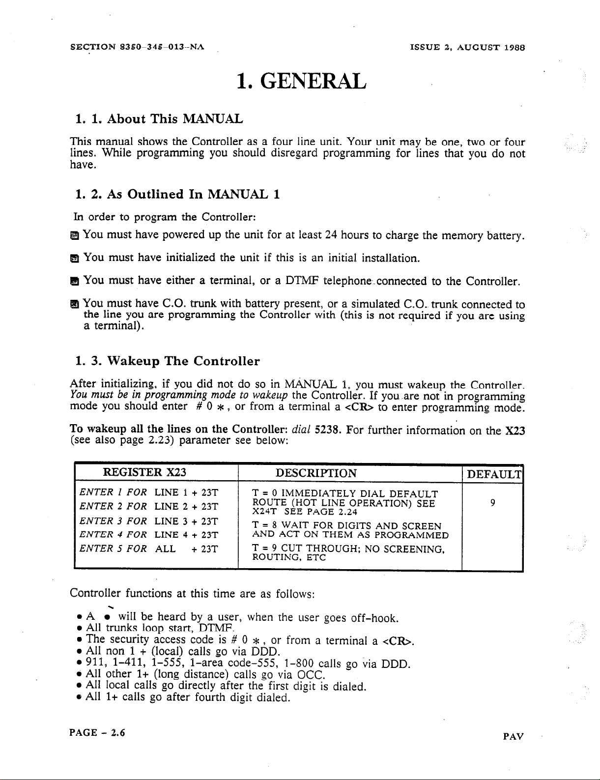
1. 3. Wakeup The Controller
After initializing, if you did not do so in MANLJAL 1, you must wakeup the Controller.
You mwf be in paagramnsirog m&e %o
mode you should enter # 0 * s or from a terminal a xCfQ> to enter programming mode.
To wakeup
all
the lines on the Controller:
(see also page 2.23) parameter see below:
REGISTER X23
ENTER I FOR
ENTER 2 FOR
ENTER 3 FOR
ENTER 4 FOR
ENTER 5 FOR
LINE 1 + 23T
LINE 2 + 23T
LINE 3 + 23T
LINE 4 + 23T
ALL
+ 23T
wakeup
I
T = 0 IMMEDIATELY DIAL
ROUTE (HOT LINE OPERATION) SEE
X24T SEE PAGE 2.24
T = 8 WAIT FOR DIGITS AND SCREEN
AND ACT ON THEM AS PROGRAMMED
T = 9 CUT THROUGH; NO SCREENING,
ROUTING, ETC
the Controller. If you are not in programming
dial 5238.
For further information on the X23
DESCRIPTION
9
Controller functions at this time are as follows:
l
A .‘ will be heard by a user, when the user goes off-hook.
l
All trunks loop start, DTMF.
l
The security access code is # 0 * , or from a terminal a <CR>.
l
All non 1 + (local) calls go via DDD.
l
911, l-411, l-555, l-area code-555, l-800 calls go via DDD.
l
All other l+ (long distance) calls go via OCC.
l
All local calls go directly after the first digit is dialed.
8 All l+ calls go after fourth digit dialed.
PAGE - 3.6
PAV
Page 29
ISSUE 2, AUGUST 1988
SECTION 8350-345013-NA
2. GENERAL NOTES ON PROGRAMMING
2. 1. Programming With a DTMF Telephone
Programming can be done using DTMF tones. The default programming code is
If your situation does not allow the entry of ## (for example: behind a PBX that will not
pass the #, or * to the Controller) you should change the programming code before
installing it. To exit programming, hang-up (go on-hook), or idle for more than 2 min-
utes while in programming mode.
2. 2. Terminating Variable Length Entries
To terminate a variable length entry (e.g. Speed Call, Account Codes,,6RX strings, etc.)
use ##. If your situation does not allow the entry of ## (For example: behind a PBX that
will not pass the ## to the Controller) there is an automatic timeout on variable length
information. The entry will be made automatically for you if you do not enter the ##
within the time specified by the inter-digit timer
(X11
by default 6 seconds. See page
2.22).
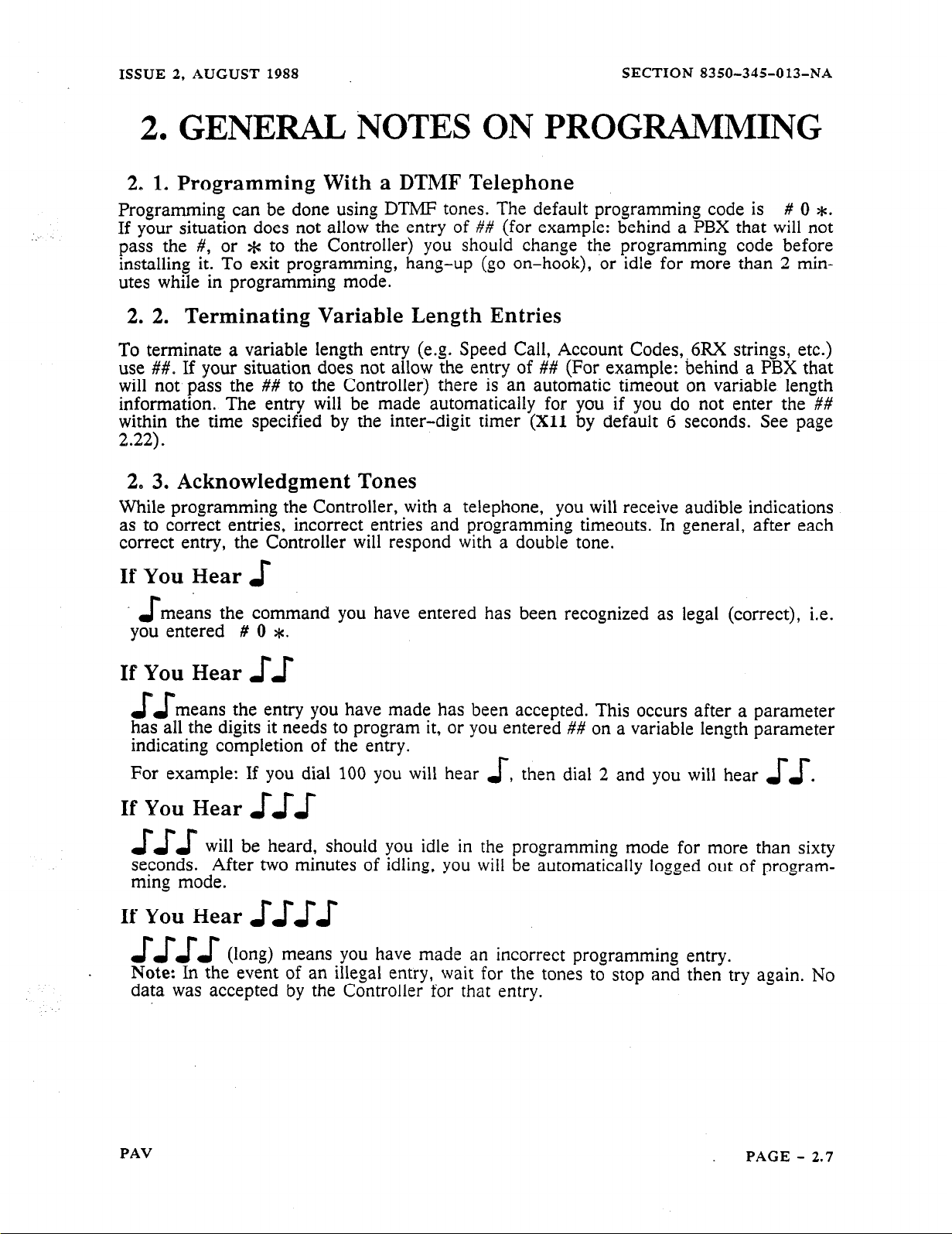
2. 3. Acknowledgment Tones
While programming the Controller, with a telephone, you will receive audible indications
as to correct entries, incorrect entries and programming timeouts. In general, after each
correct entry, the Controller will respond with a double tone.
# 0 *.
If
You Hear
means the command you have entered has been recognized as legal (correct), i.e.
-s
J-
you entered # 0 *.
If You Hear
means the entry you have made has been accepted. This occurs after a parameter
JJ
11
has all the digits it needs to program it, or you entered ## on a variable length parameter
indicating completion of the entry.
,
For example: If you dial 100 you will hear
If You Hear
J-J-J
J-u-
will be heard, should you idle in the programming mode for more than sixty
then dial 2 and you will hear
J-
J-J-
seconds. After two minutes of idling, you will be automatically logged out of program-
ming mode.
If You Hear
J-J-J-J-( >
J-J-J-J-
long means you have made an incorrect programming entry.
Note: In the event of an illegal entry, wait for the tones to stop and then try again.
data was accepted by the Controller for that entry.
.
No
PAV
PAGE - 2.7
Page 30

SECTION 8350-345013-NA
ISSUE 2, AUGUST 1988
2. GENERAL NOTES ON PROGRAMMING
Example
1IAL HEAR
942
903
500
J-
622
ar
DIAL
0
OR 1
OR2
OR3
USER’S AREA
CUSTOMER’S
AUTHORIZATION
CODE
I
DIAL
##
HEAR
I
J-J
TO TELL THE CONTROLLER:
LOo;;CESS PROGRAMMING
I
ERASE ALL PREVIOUSLY
ENTERED NON-DEFAULT
PROGRAMMING DATA AND
RELOAD DEFAULT DATA
LOOP START, ROTARY DIAL
GROUND START, ROTARY DIAI
TURN ON OFF-HOOK TONE
IJJ-I
DIALED BEFORE SENDING TO
USERS AREA CODE - 3 DIGITS
USUALLY A 3 TO 10 DIGIT
AUTHORIZATION CODE
To exit programming, hang-up (go on-hook).
2. 4.
Typical Resulting Controller Action
When the user dials a destination number the Controller will (due to the 625
Control Sequence see page 2.41):
Detect dial tone.
Dial the OCC Access Number (621).
Detect dial tone from the OCC.
Dial the Authorization Code (622).
Dial the Destination Number.
Connect the Caller to the line.
PAGE - 2.8
Access
PAV
Page 31

ISSUE 2, AUGUST 1988
SECTION 8350-345-013-NA
2. GENERAL NOTES ON PI~~MAMMING
2. 5. Terminating A Variable Length Entry
Because some commands that you will give to the Controller require variable length infor-
mation (after them) that only you will know, a terminator is required to indicate the end
of an entry. Generally this occurs with Speed Call information, 8XX and 6RX parameters.
This terminator is ##. When using a terminal you can substitute the letter A for the * and
B for the #. You can exit programming mode by dialing 999, or idle for more than 2
minutes while in programming mode.
2. 6. Programming With a Terminal
Programming can be done using a terminal (does not apply to Chain Programming, for
Chain Programming see MANUAL 3). The default programming code is <CR> (a car-
riage return). When you enter a carriage return the following screen appears:
,,
.: : . . :. .:.
..: ..:.: .:::
. . .:y::::‘. -pi:
R&tiiw
.I.
1. .; ,::. j ::
.’ :
-RING
:
,....I
PR()G
2. 7. Changing Terminal Program Security Code
MODE
At this time you may wish to change the terminal programming access code by:
..604.
->-,. ‘..
Where MMM is the new programming code and ## is the termination
MMM##:’
indicator. The
DTMI? telephone access (#O*) will not be affected.
2. 8.
Each time you enter a legal command e.g. 005, from a terminal, the
automatlcally space to
I
Legal and Illegal Entries
. aa
t Area for Data fiat You Enter To Be Displayed
Left By Legal Command
the
next entry point waiting for more input. For example:
Controller will
Should you make an illegal entry, you will receive:
> 5 FOLLOWED BY A CARRIAGE RETURN (USED TO CANCEL THE 5 ENTRY)
?5
>
0
indicates an incorrect entrv
PAV
PAGE - 2.9
Page 32

SECTION 8350-345013-NA
ISSUE 2, AUGUST 1988
2. GENERAL NOTES ON PROGRAMMING
2. 9. Tandem Mode (942 908)
The Controller can be programmed from a remote site by using a personal computer or
terminal connected to a Tandem-capable unit. This configuration allows you to dial up
and access Controllers in the customer’s premise. Programming is done using DTMF
tones supplied by the Controller as instructed by the terminal. For further information see
MANUAL 4.
2.
10. Cloning (942 906)
A
.
Controller can be programmed to operate identically to another Controller by using a
method called ‘“Cloning”. One Controller is programmed (referred to as the Master) and
then connected to another Controller you wish to program, using a Cloning cable. For
further information see MANUAL 4.
2. 11. Data Verification (902)
Data Verification is a convenient and fast way to confirm the contents of a Controllers
database. You must use a terminal to use this mode and data will be displayed for each
parameter entered. Data Verification does not alter the contents of the Controller’s data-
base. For further information see MANUAE 4.
2. 12. Special Functions
Special Function Commands are commands that allow access to specific data in the Con-
troller. If you are using DTMF Chaining, consult CHAINING PAIWVIETERS
COMMANDS in MANUAL 3 before using these commands, as they are not functional in
a chained access programming session. This is especially true when using 942 903, 942
906, 942 908. There should never be a requirement to use these commands when a Controller is in a Chain. Note: the commands are valid, however, on Chained Controllers as
long as Chain Programming has not.been accessed.
You must be in the programming mode to use these commands.
COMMANDS
902
942 903 LOAD DEFAULT DATA. DELETES ALL OTHER
942 904
942 906 ENTER CLONE iMASTER CODE.
907
942 908 ENTER TANDEM MODE
999 EXIT PROGRAMMING MODE
980MMDDHHMM
DATA CONFIRMATION MODE: AFTER EACH 2 OR 3
DIGIT PREFIX THE CONTROLLER WILL DISPLAY
PROGRAMMED DATA
EXISTING INFORMATION, RELOADS DEFAULTS
CLEAR ALL SEARCH TABLES (801-815, 821-835)
RETURN TO DATA PROGRAMMING MODE FROM DATP
CONFIRMATION M[ODE.
REMOTE CONTROLLERS)
SET THE INTERNAL CLOCK WHERE MM = MONTH,
DD = DAY, HH = HOURS, MM = MINUTES.
DEFINITION
(FOR PROGRAMMING
AND
PAGE - 2.110
PAV
Page 33

ISSUE 2, AUGUST 1988
SECTION 8350-345-013~NA
2. GENERAL NOTES ON PROGRAMMING
Figure 2.1 Programming The Controller
000 - 015
ALL 50 X
TO 53X
-l--L
PRIMARY SEARCH
TABLES
LINE/TRUNK OPTIONS
C.O. TYPE, TIMING, ETC.
50X - 53X = ALL LINES
LINE 1 LINE 2 LINE 3 LINE 4
. 10x
1’3”x 2Tpx 3Tfox qT1ox
20x
SPEED CALL
700-799
30x 40x
HOTLINE DEFAULT
ROUTE
DISABLED PASS ALL
DIGITS DIRECTLY M
THROUGH
SYSTEM WIDE OPTIONS
DISABLED
9
PRIMARY ROUTES
55X = ALL ROUTES
15x 25x
ROUTE ROUTE ROWE
1
PRIMARY ROUTES 610 -645
-’
610
613
1 623
35x
2 3 4
1 633 1
t t
DDD 1ST
0
L
occ
1
2ND 3RD
occ occ
45x
ROUTE
t t
2
I
=F=
3-4 5 6 7
SECONDARY ROUTES
w
57X = ALL ROUTES
17x
ROUTE
ALTERNATE ROUTES 650 -685
DDD
1
1ST
occ
27X
ROUTE ROUTE
2
37x
3
2ND 3RD
occ
47x
ROUTE
4
occ
Warning: When programming Dial Plan/Search T’emplates, care should be taken to not
affect calls that are dialed for emergency, e:g.
911 calls. After programming a Controller,
check that the operation of emergency dialing has not been adversely affected.
PAV
PAGE - 2.11
Page 34

SECTION
8350-345013-NA
ISSUE 2, AUGUST 1988
3. SELECTING THE CONTROLLER TYPE
3. 1. Specifying the Unit As A Call Controll& Or A PAV Controller
As
it defaults to a regular Controller when initialized, you must specify the Controller as a
PAV Controller if you wish to use it as. a Positive Account Code Verifier. This can be
done by setting
011
to 1 as shown below:
REGISTER 011”
ENTER OllT
I
DESCRIPTION 1 DEFAUL’I
T = 0 FOR REGULAR CONTROLLER
OPERATION
T = 1 FOR PAV CONTROLLER
0
PAGE - 2.12
PAV
Page 35

ISSUE 2, AUGUST 1988
4.
SYSTEM WIDE DATA
4. 1. General
You may want to change System Wide Data, because the default data does not meet your
requirements. For example, all telephone lines are specified as loop start when default
data is loaded. If you are using ground start lines, this must be changed.
There is a series of Charts in APPENDIX 2 that will aid you in recordihg the information
that you enter.
4. 2. Programming Speed Calls
Speed Calls apply on a SYSTEM wide basis, but access can be restricted. There is a
SPEED CALL Chart in APPENDIX 2 that will aid you in recording the speed calls used
and the numbers assigned to them.
4. 3. Defining The Maximum Number Of Speed Calls
You can define the maximum number of Speed Call-s by:
SECTION 8350-345013-NA
REGISTER 000 DESCRIF’TION
ENTER
Note: An additional programming change will be necessary if you selected 2 for 1,000
Speed Calls, if the Speed Call trigger is to be recognized by the Primary Search Table
and acted on.
1. The information in the 803 register (*#9#9#2) must be deleted by entering
2. A new value must be added to the 804 register as 804 *#9#9#9#2.
3. This changes the Speed Call trigger range from *NN to *NNN. The * can be
4. 4. Setting up a Speed Call Method 1
Speed Call can be programmed in one of two ways. The first is generally done at the time
of installation programming and has the following format:
OOOT
803 *#9#9#9.
a different digit if required.
T = 1 FOR
T = 2 FOR
100
SPEED
1000
SPEED CALLS MAXIMUM
CALLS
MAXIMUM
DEFAULT
1
7NN(N)DKMM...MM J~=P...PP##
## INDICATES END OF
-f
ENTRY
-r
P IS THE ACCOUNT CODE
PAV
, I
’ ‘INN(N)
IS THE SPEED CALL NUMBER
T
* INDICATES THAT THE NEXT
ENTRY BEGINS AN ACCOUNT CODE
MM IS THE PHONE NUMBER
K INDICATES HOW ROUTING WILL BE ACCOMPLISHED
D INDICATES WHICH TRUNK(S) IS TO BE ALLOWED ACCESS
LOCATTON
PAGE - 2.13
Page 36

SECTION 8350-345OP3-NA
4. SYSTEM WIDE DATA
ISSUE 2, AUGUST 1988
When you
programmed OOOT (see page 2.13), you selected either 100 or 1000 speed calls
available. To program a speed call use one of the formats in the following Chart:
REGISTER (FORMAT)
FOR
100
SPEED CALLS
7NNDKh4M...MM##
OR
7NNDKMM..
FOR
1000
MM * P. .PP##
SPEED CALLS
7NNNDKMh&..MM##
OR
7NNNDKMM...MM* P..PP##
D is
the key that selects the lines to access the call number
FORMAT FOR UP TO 100 ENTRIES.
NN IS THE SERVICE CODE TO BE DIALED BY
THE SUBSCRIBER AND MM...MM IS THE
NUMBER TO WHICH THE CODE IS TRANSLATED
FORMAT’FOR UP TO 1000 ENTRIES.
NNN IS THE SERVICE CODE TO BE DIALED BY
THE SUBSCRIBER AND MM...MM IS THE
NUMBER TO WHICH THE CODE IS TRANSLATED
DEFINITION
MUST BE ENTERED
FROM A TERMINAL
K specifies how routing will be accomplished
0 - 7 Force on Route 0 7. 7
8
Use the screening
table to determine routing
9 Dial immediate. no Route # (transoarent)
PP
is an Account Code and is se
the * . The +c and the Account c?
arated from the destination number by
ode are optional.
Enters the information into memory
Speed Call Programming Example 1: Since
the screen 803 *#9#9#2 already exists by
default, up to 100 Speed Calls with the X&N format can be programmed:
Enter 722 085551818## will cause 555-1818 to be dialed out whenever a user dials *22.
Speed Call Programming Example 2:
To program 411 calls to go to l-555-1212 you
must set OOOT to 0002. Then:
Enter 803 411 #2##, sets 411 as a Speed Call trigger digit.
Enter 7411 08
15551212## enters the Speed Call digit.
The unit is now set to dial out l-555-1212 whenever 411 is dialed into any trunk.
PAGE - 2.14
PAV
Page 37

-.
ISSUE 2, AUGUST 1988
SECTION 8350-345-013-NA
4. SYSTEM WIDE DATA
4. 5. Setting up a Speed Call Method 2
Generally, this method of programming Speed Call is used by a user after an installation
is complete. All trunks will have access to the Speed Calls and all calls will be screened
because DK as outlined previously is automatically set to 08. By default the user Speed
Call programming code is ###.
STEP
DIAL
###
NN(N)
MM...
##
DESCRIPTION
IS THE USER SPEED CALL PROGRAMMING CODE
IS THE LOCATION 00 THROUGH 99 OR 000 THROUGH
999
IS THE TELPHONE NUMBER TO BE DIALED
ENTERS THE INFORMATION
pgAEPE;TEPS 2 - 4 UNTIL ALL NUMBERS ARE
HANG UP TO EXIT. DO NOT DIAL 999
4. 6. To Use A Speed Call Number From a DTMF Phone
1. Dial * NIT(N),
entered at the Speed Call location specified will be dialed out, if it exists. If it does not
exist, or the particular trunk being accessed is not allowed access, re-order tone will be
supplied to the user.
where NN(N) is the two or three digit location number. The number
4. ‘7. To Change the Speed Call So It Can Be Accessed From a Rotary
Dial Phone
To change the Speed Call Access Code to 1lNN instead of * NN:
I.
Dial # 0 *,
2.
Dial
80411#9#9#2## add new Speed Call access code, which will be 1lNN in this case.
or the current programming access code.
3. Hang-up to exit program mode if done programming.
4. 8. If You Wish To Delete The Old Speed Call Access Code
I. While in programming mode
*N-N.
2. Hang-up to exit program mode if done programming.
Dial
803 e #9#9#9## to delete the old
access code of
4. 9. To Use The New Number From a Rotary Dial Phone
1.
Dial
1lNN where NN is the two digit location number. The number entered at the
Speed Call location specified will be dialed out, if it exists. If it does not exist, or the
particular trunk being accessed is not allowed access, re-order tone will be supplied to
the user.
PAV
PAGE - 2.15
Page 38

SECTION 8350-345-013-NA
4. SYSTEM WIDE DATA
4. 10. Re-Order Tone Supplied By the Controller
ISSUE 2, AUGUST 1988
REGISTER 001
ENTER 001 T
WHERE T IS:
0 = 400HZ,
1 = 400
DESCRIPTION DEFAUL’I
INTERRUPTED
CONTINUOUS
HZ
AT
180
IPM
0
4. 11. Trunks To Be Monitored Por Call Detail Recording
You can control which trunk(s) are to be monitored for Call Detail Recording (CDR see
page 2.17) by:
ENTER 005T
Note: C, D, E can only be entered from a terminal.
4. 12.
RS-232 Baud Rate
WHERE T IS:
:
:
REGISTEfi
ENTER 006T
006
DESCRIPTION
T = 1 FOR
T = 2
T = .3 FOR
FOR
110 T
300 T
600 T
= 4 FOR 1200
= 5 FOR 2400
= 6
FOR 4800
DEFAULT
A
4. 13. Nulls After A Carriage Return
REGISTER 007
ENTER 007T
DESCRI[PTION
T = THE NUMBER OF NULLS (O-9)
DEFAULT
2
4. 14. Print Out Incoming Calls
You can control the printing of records of incoming calls in Call Detail Recording (CDR
see page 2.17) by:
PAGE - 2.16
PAV
Page 39

ISSUE 2, AUGUST 1988
SECTION 8350-345-013-NA
4. SYSTEM
WIDE DATA
4. 15. Print Format For CDR
You can change Call Detail Recording (CDR) format as required:
l
The MIIEL format was developed for PBX applications (specifically MlTEL PBXs).
Some fields are used for call transfers, attendants, etc., and are not supplied by the
Controller.
l
The SMART format is similar to the MlTEL format, however it has reduced the printing
width to fit in 80 columns and the R field is in ASCII instead of numeric.
For further information on the print format see APPENDIX
format can be changed by:
REGISTER 009 DESCRIPTION.
ENTER 009T
T = 0 FOR OFF
T = 1 FOR ,&fITEL
T = 2 FOR SMART RETURN LINE FEED AT
T = 5 FOR M[TEL PROVIDE A CARRIAGE
T = 6 FOR S,MART RETURN LINE FEED AT
PROVIDE A CARRIAGE
START OF RECORD
START OF RECORD
AND END
1
(page 2.50). The print
DEFAUL’Z
1
4. 16. Route to Monitor
You
can specify which route(s)
REGISTER 010
ENTER OIOT
for CDR
are to be monitored for CDR by:
DESCRIPTION
T = 0 FOR
T = 1 FOR
T = 2 FOR
T = 3 FOR
T = 1 FOR
T = 5 FOR
T = 6 FOR
T = 7 FOR
T = 8 ROUTED CALLS AND OUTSIDE
CENTREX CALLS ONLY
T = 9 ALL CALLS
4. 17. Route Progress Tone Length
REGISTER 015
ENTER 015T
I DESCRIPTION
t
T = 0 JO0 MS
ROUTE 1
ROUTE 2
ROUTE 3
ROUTE 4
ROUTE 5
ROUTE 6
ROUTE 7
ROUTE 8
T = 1 100 MS
DEl?AUL?
9
DEFAUL’I
n
PAV
PAGE
- 2.17
Page 40

SECTION 8350-345-013-NA
5. LINE AND TRUNK OPTIONS
5. 1. General
ISSUE 2, AUGUST 1988
When programming line and trunk options you should remember Trunk 1 is not related to
Route 1, or Trunk 2 is not related to Route 2, etc.
Line and Trunk refer to the physical line that is supplied by your telephone company.
Route refers to the way the Controller will attempt to route the call through the Public
Switched Telephone Network.
For example: l-800 numbers may be routed on Route 0, while a l-201 is routed to a
common carrier via Route 1. Any trunk may access any Route depending on how you
program the Controller.
All entries in this part are of a predetermined length. When you have entered the correct
number of digits, the Controller will automatically accept the entry (informing as to the
correctness as outlined on page 2.7).
5. 2. Type Of Dialing And Trunk
You can specify the type of trunk as loop or ground start, and the type of dialing as
BTMP or rotary by:
REGISTER X00
ENTER I FOR
ENTER 2 FOR
ENTER 3 FOR
ENTER 4 FOR
ENTER 5 FOR
LINE 1 + OOT
LINE 2 + OOT
LINE 3 + OOT
LINE 4 + OOT
ALL
+ OOT
DESCRIPTION
T = 0 FOR LOOP START, ROTARY
T = 1 GROUND START, ROTARY
T = 2 FOR LOOP START, DTMF
T = 3 FOR GROUND START. DTMF
DEFAULT
2
_.: ., ..-
5. 3. Rotary Dialing Rates
REGISTER XOP
ENTER I FOR
ENTER 2 FOR
ENTER 3 FOR
ENTER 4 FOR
ENTER 5 FOR
PAGE - 2.18
LINE 1 + OlT
LINE 2 + OlT
LINE 3 + OlT
LINE 4 + OlT
ALL + OlT
DESCRIPTION
T = 2 FOR OUTPULSE AT 30120 MS 20 PPS
WHICH EQUATES TO 60% BREAK
T = 4 FOR OUTPULSE AT 60140 MS 10 PPS
WHICH EQUATES TO 60% BREAK
1
DEFAULI
4
I
.
.-.
.__
PAV
Page 41

ISSUE 2, AUGUST 1988
SECTION 8350-345-013-NA
5.
LINE AND TRUNK
5.
4. DTMF Dialing Rates
RJZGISTER X02
ENTER 1 FOR
ENTER 2 FOR
ENTER 3 FOR
ENTER 4 FOR
ENTER 5 FOR
LINE 1 + 02T
LINE 2 + 02T
LINE 3 + 02T
LINE 4 + 02T
ALL
+ 02T
T = ; $ lMi(fast)
1 :MS T 2 60
T=3 70MS
T = 4 80 MS.
T = 5 90 MS
5. 5, On Hook Time
You
can specify the on-hook recognition time by:
REGISTER X03
ENTER 1 FOR
ENTER.2 FOR
ENTER 3 FOR
ENTER 4 FOR
ENTER 5 FOR
LINE 1 + 03T
LINE 2 + 03T
LINE 3 + 03T
LINE 4 + 03T
ALL
+ 03T
T = 0 FOR 80 MS T = 6 FOR 750 MS
T = 1 FOR 100 IMS T = 7 FOR 1000 MS
T = 2 FOR 150 MS
T = 3 FOR 200 MS
T = 4 FOR 300 MS T = * FOR 2 S
T = 5 FOR 500 MS T = # FOR 2.5s
DESCRIPTION
DESCRIPTION
OPTIONS
T = 6 100 MS
.T = 7 110 MS
T = 8 120 MS
T = 9 130 MS(slow)
T = 8 FOR 1330 MS
T = 9 FOR 1660 MS
DEFAULT
1
DEFAUL’I:
6
Note:
There is a relationship between X03 and X04 (see page 2.20). If X03 is less than
X04, all switch-hook flashes will be recognized as on-hooks as outlined below:
0
FLASH TIME
AS SET BY
X04T
IS SET TO MORE THAN THE ON-HOOK TIME
TIME
ON-HOOK TIME
IF THE FLASH TIME
THE FLASH IS NOT ALLOWED
INTERVALS
AS SET BY
X03T
*
PAV
PAGE - 2.19
Page 42

SECTION 8350-34%013-NA
ISSUE 2, AUGUST 1988
5.
LINE
AND TRUNK OPTIONS
5. 6. Flash Allowed Time
1 REGISTER X04
ENTER I FOR
ENTER 2 FOR
ENTER 3 FOR
ENTER 4 FOR
ENTER 5 FOR
TO DISABLE THE
LINE 1 + 04T
LINE 2 + 04T
LINE 3 + 04T
LINE 4 + 04T
ALL
FLASH
+04T 1 gg$J) ~igjJ/j:
SPECIFY A TIME
DESCRIPTION
THAT IS GREATER
THAN
XO?T
Note: This feature should generally be set to #, except in those cases where you require
the ability to use conference features. This is usually required for C.O. conference feature, or when betweebn the user’s equipment (telephone or Key system) and a PBX.
DEFAULT
I
5, ‘7. Time Between Trunk Release And Next Attempt to Connect
ENTER ! FOR
ENTER 2 FOR
ENTER 3 FOR
ENTER 4 FOR
ENTER 5 FOR
LINE 1 + 05T
LINE 2 + 05T
LINE 3 + 05T
LINE
4 + 05T
ALL
T = 0 FOR
T = 1 FOR
T = 2 FOR
T = 3 FOR
T = 4 FOR
500 MS T
650 MS T
800 MS T
950 MS T
IL100 MS T
= 5 FOR 1250 MS
= 6 FOR 1400 MS
= 7 FOR 1550 MS
= 8 FOR 1400 MS
= 9 FOR 1850 MS
5. 8. Ground Start Attempts
If you have a ground start trunlc, you can specify the number of ground start attempts. In
most cases this should not have to be changed.
REGISTER
ENTER % FOR
ENTER 2 FOR
ENTER 3 FOR
ENTER 4 FOR
ENTER 5 FOR
X06
LINE 1 + 06T
LINE 2 + 06T
LINE 3 + 06T
LINE 4 + 06T
ALL
+ 06T
DESCRIITION
T = THE NUMBER OF TIMES THE
CONTROLLER WILL ATTEMPT TO
CONNECT TO A GROUND START
TRUNK BEFORE STOPPING
DEFAUL’I
PAGE - 2.20
PAV
Page 43

ISSUE 2, AUGUST 1988
SECTION 8350-345-013-NA
5. LINE. AND TRUNK- OPTIONS
5. 9. Ground Start Attempt Timer
If
you have a ground start trunk, you can specify ground start attempt time, which in most
cases should not have to be changed:
REGISTER X07
ENTER 1 FOR
ENTER 2 FOR
ENTER 3 FOR
ENTER 4 FOR
ENTER 5 FOR
LINE 1 + 07T
LINE 2 + 07T
LINE 3 + 07T
LINE 4 + 07T
ALL
+ 07T
DESCRIPTION
T = THE AMOUNT OF TIME IN SECs.
CONTROLLER WILL ATTEMPT TO
CONNECT TO A GROUND START
TRUNK BEFORE STOPPING
DEFAULI
3
5. 10. Off-Hook Digit Refusal Time
You can specify the time between a user going off-hook and when the Controller will
accept digits on a per trunk basis. The time can be set by:
REGISTER X08
ENTER 1 FOR
ENTER 2 FOR
ENTER 3 FOR
ENTER 4 FOR
-
ENTER 5 FOR
LINE 1 + 08T
LINE 2 + 08T T = 1 FOR .I SEC
LINE 3 + 08T
LINE 4 + 08T
ALL + OBT
Note: In the PAV Controller, if X19T (see page 2.23) Off-Hook Progress Tone is set to a
1 or enabled, the progress tone will not occur until the X08T (see page 2.16) timer has
expired or reached 700 ms. The off-hook progress tone is 200 ms in duration.
.
DESCRIPTION
T = 0 FOR
T = 2 FOR .2 SEC
T = 3 FOR .3 SEC T = 8 FOR .8 SEC
T = 4 FOR .4 SEC
NONE
T = 5 FOR .5 SEC
T = 6 FOR .6 SEC
T = 7 FOR .7 SEC
T = 9 FOR .9 SEC
DEFAULT
3
5. 11. User Dial Tone
You can specify the dial tone
is dialing as silent, or ticking
REGISTER X09
ENTER 1 FOR
ENTER 2 FOR
ENTER 3 FOR
ENTER 4 FOR
ENTER 5 FOR
LINE 1 + 09T
LINE 2 + 09T T = 0
LINE 3 + 09T
LINE 4 + 09T
ALL
+ 09T
*You should note that internal dial tone interacts with the X19 (see page 2.23) feature.
PAV
supplied, and what the caller will hear while the Controller
by:
I
DESCRIPTION
SILENT DAILOUT
NONE
T = 1 INTERNAL*
T.= 4 FROM C.O.
TICKING DIALOUT
T = 2 NONE
T = 3 INTERNAL*
T = 6 FROM C.O.
DEFAULT
4
PAGE - 2.21
Page 44

SECTION 8350-345-013-NA
5. LINE AND TRUNK OPTIONS
5.
12. Interdigit Time Out Subscriber Side
ISSUE 2, AUGUST 1988
REGISTER Xl 1
I
ENTER I FOR
ENTER 2
ENTER 3
ENTER 4
ENTER 5 FOR
FOR
FOR
FOR
LINE 1 + flT
LINE 2 + 11T
LINE 3 + 11T
LINE 4 + 1lT
ALL
+ 1fT
T = 0 FOR NO TIMEOUT
T = 1 FOR 2 SEC T
T = 2 FOR 4 SEC T
T = 3 FOR 6 SEC T
T = 4 FOR 8 SEC T
T = 5 FOR 10 SEC :
DESCRIPTION
5, 13. Interdigit Time Out On O+ Calls
REGISTER X12
ENTER 1 FOR
ENTER 2 FOR
ENTER 3 FOR
ENTEk 4 FOR
ENTER 5 FOR
LINE 1 + 12T
LINE 2 + %%T
LINE 3 += l2T
LINE 4 + f2T
ALL
+ 12T
I
T = 0 FOR NO TIMEOUT
T = 1 FOR 2 SEC T
T = 2 FOR 4 SEC T
T = 3 FOR 6 SEC T
T = 4 FOR 8 SEC T
T = 5 FOR 10 SEC :
DESCRIPTION
5. 14. Interdigit Time Out On Ol+ Calls
REGISTER Xl3 DESCRIPTION
ENTER % FOR
ENTER 2
ENTER 3
ENTER 4
ENTER 5 FOR
LINE 1 + 13T T = 0 FOR NO TIMEOUT
FOR
LINE 2 = + 13T
FOR
LINE 3 + l3T
FOR
LiNE 4 + l3T
ALL + 13T
T 1 FOR 2 SEC T
T = 2 FOR 4 SEC T
T = 3 FOR 6 SEC T
T = 4 FOR 8 SEC T
T = 5 FOR 10 SEC
= 6 FOR 12 SEC
= 7 FOR 14 SEC
= 8 FOR 16 SEC
= 9 FOR 18 SEC
= * FOR 20 SEC
= # FOR 22 SEC
= 6 FOR 12 SEC
= 7 FOR 14 SEC
= 8 FOR 16 SEC
= 9 FOR 18 SEC
= * FOR 20 SEC
= # FOR 22 SEC
= 6 FOR 12 SEC
= 7 FOR 14 SEC
= 8 FOR 16 SEC
= 9 FOR 18 SEC
= * FOR 20 SEC
;
= # FOR 22 SEC
( DEFAULS
3
DEFAUL1
2
DEFAULT
5. 15. Rotary Interdigit Pause On Calls On Outgoing Dialing
REGISTER Xl4
ENTER 1
ENTER 2
ENTER 3
ENTER 4 FOR
ENTER 5 FOR
PAGE - 2.22
FOR
FOR
FOR
LINE 1 + 14T
LINE 2 + 14T
LINE 3 + 14T
LINE 4’+ 14T
ALL + 14T
DESCRIPTION
T = 0 400 MS T =
T = 1 500 MS
T = 2 600 MS
T =
3 700 hii
T
T =
T =
4 800 MS
2 ~O$o#
r -
7
1.1 S&Z
8 1.2
SEC
DEFAUL’J
4
PAV
Page 45

ISSUE 2, AUGUST 1988
5.
LINE AND TRUNK OPTIONS
SECTION 8356345-613-NA
5. 16. Off-Hook Tone
You
can specify whether, or not, a caller will receive an Off-Hook Tone. The tone is 200
mS in duration, and if enabled, will occur after the
expired, or reached 700 mS. Note: If the Off-Hook Tone is enabled and internal dialtone
has been programmed, the Off-Hook Tone will be 300 mS long, followed by NO dialtone.
The Off-Hook Tone is controlled on a per trunk basis by:
XOST
timer (see page 2.21) has
REGISTER X19
I
ENTER I FOR
ENTER 2 FOR
ENTER 3 FOR
ENTER 4 FOR
ENTER t7 FOR ALL
LINE 1 + 19T
LINE 2 + 19T
LINE 3 t 19T
LINE 4 + 19T
+ 49T
I
DESCRIPTION
WHERE T IS:
0 FOR DISABLED
1 FOR ENABLED
DEFAULl
I
5. 17, Incoming Call Detection
You can specify the Controller’s’sensitivity to incoming ringing on a scale of 0 to 9 (where
0 is the most sensitive and 9 the least). If the setting is too sensitive you will receive false
incoming calls. If the setting is not sensitive enough, you may miss incoming calls as the
Controller will not detect them. It should not be necessary to change the default value for
normal operation, but you can by:
REGISTER X20
ENTER 1
ENTER 2
ENTER 3 FOR
ENTER 4 FOR
ENTER 5 FOR
F-OR
FOR
I
LINE 1 + 20T
LINE 2 + 20T WHERE 9 IS LEAST SENSITIVE AND 0 IS
LINE 3 + 20T
LINE 4 + 20T
ALL
+ 20T I
WHERE T IS ENTERED AS 0 THROUGH 9.
MOST SENSITIVE
DESCRIPTION
DEFAULT
2
5. 18. Controller Operation 0,n Off-Hook
When the Controller loads default data, it will not yet screen or route digits dialed by a
user. You change this for each trunk by:
REGISTER X23
ENTER I FOR
ENTER 2 FOR
ENTER 3 FOR
ENTER 4 FOR
ENTER S FOR
PAV
LINE 1 t 23T
LINE 2 t 23T
LINE 3 t 23T
LINE 4 t 23T
ALL t 23T
DESCRIPTION
T = 0 IMMEDIATELY DIAL DEFAULT
ROUTE (HOT LINE OPERATION) SEE
X24T (SEE PAGE 2.24)
T = 8 WAIT FOR DIGITS AND SCREEN
AND ACT ON THEIM AS PROGRAMMED
T = 9 CUT THROUGH; NO SCREENING,
ROUTING, ETC
1 DEFAUL’I
9
I
PAGE - 2.23
Page 46

SECTION 83§@-345013-NA
ISSUE 2. AUGUST 1988
5. LINE AND TRUNK OPTIONS
5.
19. Specify Default Route
You can specify a default route for a trunk (see also #8 Action Digit) by:
ENTER 2 FOR
ENTER 3 FOR
ENTER 4 FOR
$
For the Route specified here to be in effect, X23 (see page 2.23) must be set to X230 or
LINE 2 + 24T
LINE 3 + 24T
LINE 4 + 24T
a #8 (Action Digit) must occur in the Primary Search Table (after the number dialed has
been matched). This will cause the Controller to use a specific Route. If a Route O-3 has
been selected (through programming) all calls will be routed on the Primary Route. If a
Route 4-7 has been selected (through programming) all calls will be routed on the Alternate Route.
5. 20. Specify The Digit For Centrex Access
You can specify the digit to be used for outgoing centrex access. This usually occurs when
the Controller is placed behind a Centrex or PBX unit and you are required to dial a digit
- typically a 9 - to access the outside line. If the Controller detects a Centrex Access Digit.
it will screen the remaining digits and process the call. If the Controller does not detect a
Centrex Access Digit it will not screen and just dial.
REGISTER X25
ENTER I FOR
ENTER 2 FOR
ENTER 3 FOR
ENTER 4 FOR
ENTER 5 FOR
LINE 1 + 25T
LINE 2 + 25T
LINE 3 + 25T
LINE 4 =+ 25T
ALL
+ 25T
WHERE T IS THE CENTREX DIGIT.
IF X26T = X261 (BELOW) THEN ALL INTRA
CENTREX CALLS ARE DIALED
IMMEDIATELY
DESCRIPTION
DEFAULT
.
9
5. 21. Centrex Enable/Disable
You can enable or disable the Centrex by:
REGISTER X26
ENTER I FOR
ENTER 2 FOR
ENTER 3 FOR
ENTER 4 FOR
ENTER 5 FOR
PAGE - 2.24
LINE 1 + 26T
LINE 2 + 26T
LINE 3 + 26T
LINE 4 + 26T
ALL
+ 26T
WHERE T IS:
0 FOR DISABLE
1 FOR ENABLE
DESCRIPTION
DEFAULT
0
PAV
Page 47

ISSUE 2, AUGUST 1988
SECTION 8350-345-013-NA
5. LINE AND
TRUNK OPTIONS
5. 22. Time To Auto-Answer
You can specify the time the Controller
detection of ringing by:
REGISTER X27
ENTER I FOR
ENTER 2 FOR
ENTER 3 FOR
ENTER 4 FOR
A
ENTER
5.
5 FOR
23. Wait For Security Code Timer
LINE 1 t 27T
LINE 2 t 27T
LINE 3 t 27T
LINE 4 t 27T
ALL
t 27T
T = 0 FOR DISABLE
T = 1 FOR 10 S
T = 2 FOR 20 S
T = 3 FOR 30 S
T = 4 FOR 40 S
T = 5 FOR 50 S
This parameter specifies the time in which a security code (603 Parameter see 7. 3. on
page 2.33) must be entered on a trunk after the Controller auto-answers. If timeout oc-
curs or an incorrect password is entered, the trunk will be locked as specified in the X29
parameter (next parameter discussed). The time to wait for password can be changed by:
REGISTER X28
ENTER 1 FOR
ENTER 2 FOR
ENTER 3 FOR
ENTER 4 FOR
ENTER 5 FOR
LINE 1 t 28T
LINE 2 t 28T
LINE 3 t 28T
LINE 4 t 28T
ALL
+ 28T
T = 0 FOR DISABLE
T = 1 FOR 10 S
T = 2 FOR 20 S
T = 3 FOR 30 S
T = 4 FOR 40 S
T = 5 FOR 50 S
waits before answering an incoming call after the
DESCRIPTION
T = 6 FOR 60 S
T = 7 FOR 70 S
T = 8 FOR 80 S
T = 9 FOR 90 S
*FOR 100 S
: = # FOR 120 S
DESCRIPTION
T = 6 FOR 60 S
T = 7 FOR 70 S
T = 8 FOR 80 S
T = 9 FOR 90 S
*FOR 100 S
: I# FOR 120 S
DEFAULT
0
DEFAULT
6
5. 24. Incorrect/Failed Security Code Trunk Lockout Timer
Failure to enter the correct programming password during the time specified by the X28
parameter enables this timer. You can specify the time a trunk is locked out. If the
timeout occurs, or an incorrect password is entered, the trunk will be locked out’as specified, or until on the user side of the line goes off-hook. The time for password can be
changed by:
REGISTER X29
ENTER 1 FOR
ENTER 2
ENTER 3 FOR
ENTER 4 FOR
ENTER 5 FOR
PAV
FOR
LINE
LINE 1 t 29T
LINE 2 t
LINE
ALL
29T T = 1 FOR
29T
3 t
29T
4
t
t 29T
T = 0 FOR DISABLE
T
T
T
T = 5 FOR 50 S
DESCRIPTION
= 2 FOR 20 S T = 7 FOR
= 3 FOR 30 S T = 8 FOR
= =
4 FOR -10 S T 9 FOR
10 S
T = 6 FOR 60 S
T= *FORlOOS
T = # FOR 120 S
70 S
80 S
90 S
DEFAUL’I
9
PAGE
- 2.25
Page 48

SECTION 8350-345013-NA
5. LINE AND TRUNK OPTIONS
5.
25. Off-Hook Recognition Timer
ISSUE 2, AUGUST 1988
REGISTER X30
I
ENTER I FOR
ENTER 2 FOR
ENTER
ENTER 4 FOR
ENTER 5 FOR
3 FOR
I
LINE 1 + 3OT
LINE 2 + 30T 0=20 MS - 4= 80 MS 8 = 160 MS 3
LINE 3 30T
LINE 4 + 30T 3 = 60 IMS 7 = 140 MS # = 220 MS
ALL
+ 2 40 = MS 65=120MS *=2OOMS
+ 30T
‘WHERE T IS:
DESCRIPTION
1 = 20 MS
= 100 MS 9 = 180 MS
DEFAUL’I
I
5. 26. Tip Ground Application Recognition Timer
This command selects the time that a tip ground must be applied on a ground starttrunk,
for that application to be recognized. If you are using a terminal you can substitute the
letter A f6; the * and B for the #.
REGISTER X31
ENTER I FOR
ENTER 2 FOR
ENTER 3 FOR
ENTER 4 FOR
ENTER S FOR
LINE 1 i- 31T T = 0 FOR 40 MS T = 6 FOR 240 MS
LINE 2 + 31T T = 1 FOR 40 MS .T=7FOR280MS 3
T = 2 FOR 80 MS T = 8 FOR 320 MS
LINE 3 -I= 3lT T = 3 FOR 120 MS T = 9 FOR 360 MS
LINE 4 T 4 FOR 160 MS + 3lT
T = 5 FOR 200 MS
ALL + 3lT
DESCRIFTXON
=
DEFAULT
: I# *FOR 400 MS
FOR 440 MS
5. 2’7* Digit Recognition On Outgoing Calls
R.EGISTER X32
ENTER I FOR
ENTER 2 FOR
ENTER 3 FOR
ENTER 4 FOR
ENTER 5 FOR
PAGE - 2.26
LINE 1 -I- 32T
LINE 2 -+ 32T
LINE 3 + 32T
LINE 4 + 32T
ALL
+ 32T
I
DESCRIPTION
T = 0 FOR ALLOW DTMF, JO OR 20 PPS
T = 1 IGNORE ALL ROTARY
T = 2 IGNORE ALL DTMF
T = 3 IGNORE ALL DIGITS
T = 5 FOR GO TO REORDER ON ROTARY
T = 6 FOR GO TO REORDER ON DTMF
T = 7 FOR G.0 TO REORDER ANY DIGITS
1
DEFAULl
0
_
PAV
Page 49

ISSUE 2. AUGUST 1988
5. LINE AND TRUNK OPTIONS
5. 28. Digit Recognition On Incoming Calls
SECTION 8350-345-013-NA
REGISTER X33
ENTER I FOR
ENTER 2 FOR
ENTER 3 FOR
ENTER 4 FOR
ENTER 5 FOR
LINti 1 + 33T
LINE 2 + 33T
LINE 3 + 33T
LINE 4 + 33T
ALL
+ 33T
’ T = 1 IGNORE ALL ROTARY
. T = 7 FOR GO TO REORDER ANY DIGITS
DESCRIPTION
T = 0 FOR ACCEPT DTMF, 10 OR
T = 2 IGNORE ALL DTMF
T = 3 IGNORE ALL DIGITS
T = 5 FOR GO TO REORDER ON ROTARY
T = 6 FOR GO TO REORDER ON DTMF
T = 8 ALLOW DTMF OR 10 PPS ROTARY,
IGNORE ‘20 PPS ROTARY
T = A ALLOW 10 PPS ROTARY, IGNORE
DTMF AND 20 PPS ROTARY
T = D GO TO REORDER ON 10 PPS
ROTARY, IGNORE 20 PPS ROTARY
T = E GO TO REORDER.ON.DTMF,
ALLOW 10 PPS ROTARY,..IGNORE
20 PPS ROTARY
Note: The A, D and E can only be programmed from a terminal.
20
PPS
DEFAULT
0
a
5. 29. Tip Ground Removal Timer
This command s&lects the time period for the tip ground removal detection. If you are
using a terminal you can substitute the letter A for the * and B for the #.
REGISTER X34
ENTER 1 FOR
ENTER 2 FOR
ENTER.3 FOR
ENTER 4 FOR
ENTER 5 FOR
I
LINE 1 + 34T T
LINE 2
LINE 3 + 34T
LINE 4 + 34T
ALL
-I; 34T
+ 34T
T
T
T = 3 FOR 260 MS
T
T = 5 FOR -120 MS
T = 6 FOR 500 IMS
T
T
DESCRIF’TION
= 0 FOR 100 MS T =
=
1 FOR 100 T=
= 2 FOR 180 MS T =
= 4 FOR 340 MS
= 7 FOR 580 MS
= 8 FOR 660 MS
MS
T = C FOR 980 MS
T = D FOR 1060 MS
T = E FOR 1140 MS
T = F FOR 1220 MS
9 FOR 740 MS
*FOR820MS
# FOR 900 .MS
1 DEFAUL’J
6
PAV
PAGE - 2.27
Page 50

-..
SECTION 8350-34§-013-NA
ISSUE 2, AUGUST 1988
-.
6. PRIMARY SEARCH TABLES
6. 1. General
6. 2. Primary Search Tables
Primary Search Tables consist of a three digit prefix always starting with an ‘8’ as the
first digit followed by two digits that indicate how long the digit string will be. The following digits soecifv the number for the Controller to monitor for. followed by an action digit
tefiingthe aController what to do once the string has been detected. For
803 611#6##
1 1 / ?I-ERMIN*TOR
I
LAST DIGIT OF PHONE NUMBER HAS BEEN DL4LED
MONITOR FOR 611
I
PRIMARY TABLE NUMBER IS 8 AND 03 MEANS EXPECT. THREE
Primary Search Tables are used to provide call control (Toll. Control) and -routing information Digits dialed by a caller are screened from 1 to 15 digits, depending on the
Primary Search Table you select. They can be subject to an action (as described in
Figure 2.2 ). The Controller provides 30 Search Tables - 15 PRIMARY and 15 ALTERNATE. These Tables are numbered 801 - 815 for PRIMARY and 821 to 835 for ALTERNATE. If you require ALTERNATE Search Tables consult MANUAL 4..
There is a SUCH TABLE form in APPENDIX 2 that will help you to record the digits
you enter in each Primary Search Table.
example:
DIGITS
6. 3. Warning
V&en programming Search Tables, care should be taken to not affect calls that are dialed
for emergency, e.g. 911 calls. After programming a Controller, check that the operation
of emergency dialing has not been adversely affected.
6. 4. Digits In A Table
When selecting a Primary Search Table you must enter enough digits to fill the Search
Template in the Primary Search Table you have selected. For example, if you select
Primary Search Table 815, you must enter 15 digits to fill the Search Template. Consult
the following table as to the number of digits you must enter in each Primary Search
Table.
PAGE - 2.28
PAV
Page 51

,,.,:-
ISSUE 2, AUGUST 1988 SECTION 8350-345-013-NA
6. PRIMARY SEARCH TABLES
PRIMARY’ YOU MUST ENTER THIS NUMBER OF DIGITS IN THE TABLI
SEARCH
TABLE
PLUS AN ACTION DIGIT
THE CONTROLLER WILL EXPECT TO SCREEN
THE NUMBER OF DIGITS THE TABLE SPECIFIES
AND YOU MUST ENTER ENOUGH DIGITS TO FILL
THE TABLE. FOR EXAMPLE:
803 MUST HAVE THREE DIGITS TO SCREEN.
HENCE 803 WILL USUALLY BE USED TO SCREEN
THREE DIGIT CODES LIKE CENTRAL OFFICE
CODES AND AREA CODES.
..-
The actual Search Templates structure of the Primary Search Table is shown in
Figure 2.2 . This figure also includes the Action codes that are applicable to the Search
Templates.
PAV
PAGE - 2.29
Page 52

SECTION
835O-345013-NA
ISSUE 2, AUGUST
6. PRIMARY SEARCH TABLES
Figure 2.2 Search Table Format and Action Codes
115 IS THE REGISTER NUMBER. WHERE THE 8 INDICATES A SEARCH TABLE
TOLLOWING TWO DIGITS INDICATE THE NUMBER OF DIGITS TO BE SCREENED, IN THIS
:ASE THE CONTROLLER SCREENS 15 DIGITS.
$NN ARE DIGITS YOU WANT THE CONTROLLER TO MATCH TO
J MAY BE ANY DIGIT 0 - 9 AND *
XALED BYTHE SUBSCRIBER. N CAN ALSO BE: #O
i REPRESENTS THE ACTION DIGITS INSTRUCTING THE ACTION TO BE TAKEN WHEN A MATCH
>R ENOUGH DIGTS HAS OCCURED.
f#
INDICATES THE END OF THE ENTRY
WHICH WILL BE MATCHED AGAINST THE DIGITS
FURTHER INFORMATION SEE BELOW
A
ACTION CODE DIGITS
COMPARE AGAINST A USER DIALED #
#I COMPARE AGAINST A USER DIALED 1 OR 0
#4 COMPARE AGAINST ANY USER DIALED DIGIT 2 - 9
#9 COMPARE AGAINST ANY USER DIALED DIGIT
1988
FER ROUTE #1
PREFER ROUTE #2
PREFER ROUTE #3
FORCE ROUTE #O
FORCE ROUTE #I
FORCE ROUTE #2
FORCE ROUTE #3
SELECT ROUTE #O
SELECT ROUTE #l DIGITS
SELECT ROUTE #2 OVER AGAIN FROM THE FIRST DIGIT
SELECT ROUTE #3
SPEED CALL - ACCESS 7NN ENTRY
DIAL WHAT HAS BEEN ENTERED AND CUT THROUGH(N0 ROUTING)
PROGRAMMING SECURITY CODE
ABSORB WHAT HAS BEEN ENTERED AND CUT THROUGH(BY-PASS
CONTROLLER)
LAST DIGIT OF THE PHONE NUMBER HAS BEEN DIALED. FURTHER
DIGITS DIALED ARE ACCOUNT
CODES ARE ENABLED; OTHERWISE FURTHER DIGITS ARE IGNORED.
DIALING INFORMATION MUST HAVE BEEN SCREENED PRIOR TO
ENCOUNTERING A SEARCH TABLE WITH THiS CODE TO PROVIDE
ROUTE ON WHICH TO DIAL
DO.NOTHING(WAIT FOR MORE DIGITS)
PREFER DEFAULT ROUTE SPECIFIED IN X24T
WHEN ENTERED AS A PROGRAMMING ACTION THE ENTRY IS REMOVED
(I.E. 803#00 * #9) REMOVES THE PROGRAMMING CODE # 0 *
SUBSCRIBER SIDE
CODE. THIS PERMITS A USER TO ENTER SPEED CALL NUMBERS IN THE
7NN08MM.. .MM## FORMAT., BY JUST DIALING THE NNMMM.. .MM
DIGITS BY DIALING THE SPEED CALL LOCATION NUMBER AND THE
NUMBERS
ONLY, LIMITED
THE ROUTE SELECTED COULD BE CHANGED LATER ON
IN THE DIALING SEQUENCE, AS MORE DIGITS ARE
RECEIVED
THESE CODES WILL FORCE THE CALL ONTO
THE ROUTE SPECIFIED.
FORCED, NO CHANGE OF ROUTES MAY OCCUR
THESE WILL NOT DIAL OUT THE *SELECT*
AND WILL START THE COMPARISONS
FOLLOWING THE ‘SELECT’ DIGITS
CODES, UNLESS
ONCE A ROUTE IS
R54T = 1 IF ACCOUNT
A
ACCESS SPEED CALL PROGRAMMING
t Tk~e
digit C can only be entered from a terminal. The # is used as a shift character where #O, #l, #2, etc.
would be considered as one digit.
PAGE - 2.30
PAV
Page 53

_. ISSUE 2, AUGUST 1988
SECTION 8350-345Ql3-NA
6. PRIMARY SEARCH TABLES
6. 5. Default Data
The following outlines the default data that is loaded into each Primary Search Table (as
a Search Template) and a brief explanation of each piece of data.
6. 6. Search Tables 801
Note 1 Note 2 Note 3
Note 1: If the first digit dialed by the user is a 1 the Controller will do nothing.
Note 2: If the first digit dialed by the user is a * the Controller will do- nothing.
Note 3: If the first digit dialed by the user is not a 1 or * the Controller will prefer
route 0.
6. 7. Search Tables 803
Note 1 Note 2 Note 3 Note 4 Note 5 Note 6
Note 1:
Alternate end-user speed dial programming access code, used in a situation
where the Controller is behind a device that will not pass ### (see Note 6).
Note 2:
If the digits dialed by the user are 911 the Controller will stop searching, dial
911 and cut-through.
Note 3:
A * + two more digits specify a speed call number to be
dialed.
Note 4: This specifies the Programming Access Security Code as # 0 *
.
Note 5: Specifies the PAV List Maintenance Access Security Code as # * *.
Note 6:
Specifies the end-user as speed dial programming access code ###.
6. 8. Search Tables 804
Note 1 Note 2
Note 1: Dial and cut-through after 1411.
Note 2: Prefer to place 1555 calls on Route 0.’
Note 3: Prefer to place 1800 calls on Route 0.
Note 4: Prefer to place 1NXX calls on Route 1.
Note 5: Alternate program access code (any digit plus #O*).
Note 3
Note 4
Note 5
PAV
PAGE - 2.31
Page 54

SECTION 8350-345013-NA
6. PRIMARY SEARCH TABLES
6. 9. Search Tables 807
ISSUE 2, AUGUST 1988
Note 2
#9 #9
#9 #9
1 #4
Note
#l #9
1
5 5
5 0
#4 #4 #9
Note 1: Place l+N(O or 1)X-555-XxXx (XXXX not in screen) calls on route 0.
Note 2: Stop searching after receipt of NNX-XXXX (local call).
6. 10. Search Tables 808
Note
1
#l
#4
Note
1:
Stop searching after receipt of (0 or 1) NNX-XXX% (long distance. inside the
area code)
D
#9 #9 #9 #9 #6
6. 1%. Search Tables 810
Note
1
#6
Note 1: Stop searching after receipt of N (0 or I) jc-XXX-XxXx (long distance outside
the area code).
6. 12. Search Tables 811
Note 1
#l
#4 #l #9 #9 #9 #9 #9 #9 #9 #9 #6
Note 1: Stop searching after receipt of 0 or 1 +N (0 or
1) X -XXX-XxXx (long &stance
outside the area code).
6. 13. Special Note
To enable OCC dialing, 621 (OCC access code), and 622 (authorization code) values
must be programmed. The 601 (area code) should be programmed.
6. 14. Warning
When programming Dial Plan/Search Templates, care should be taken to not affect calls
that are dialed for emergency, e.g. 911 calls. After programming a Controller, check that
the operation of emergency dialing has not been adversely affected.
PAGE - 2.32
PAV
Page 55

ISSUE 2, AUGUST 1988
SECTION 8350-345013-NA
7. COMMON OPTION DATA
Common Option Data refers to data that is common to all aspects of the Controller. Each
entry must be terminated with a “W’.
7. 1. User Area Code
You can define the user area code and it can be output automatically for calls in that area
code:
1 REGISTER 601 1
ENTER 601 xxx
DESCRIPTION
THIS AREA CODE IS INSERTED INTO THE DIGITS BEING
DIALED OUT WHENEVER THE DESTINATION NUMBER
FORMAT (RSOT) CALLS FOR THE ADDITION OF THE
AREA CODE FOR THAT SPECIFIED ROUTE.
DEFAUL’I
I
ooo
7. 2. Machine Identifier
Every Controller may be assigned a unique ID. This is especially useful when using chaining or RS-232 multiplexer, as it keeps the machines identified in their CDR outputs (see
also Al. 2 ).
REGISTER 602 DESCRIPTION
ENTER 602 xxx
THIS ID MUST BE ENTERED AS ASCII AND CAN’T BE
MORE THAN 15 CHARS., BUT ONLY THE FIRST THREE
CHARS. APPEAR ON THE CDR. THIS MUST BE ENTERED
IN ASCII HEX. SEE APPENDlX 1.
DEFAULT
43484E
KJv
Note: If you are using a PAV Controller (non-chaining) the default will be 504156 (PAV).
7. 3. Auto-Answer Security Code
You
can enter a security code that must be dialed by an incoming caller to program the
Controller. The Controller will auto-answer the incoming call and the security code must
be entered at that time (see 5. 22.
,
5.
23. and 5. 24. on page 2.25). To enter a code:
REGISTER 603
ENTER 603 xx
WHERE XX REPRESENTS THE DIGITS TO BE DIALED
TO ENTER PROGRAIMMING MODE WHEN THE
CONTROLER AUTO-ANSWERS. (MAXIMUM 33 DIGITS)
DESCRIPTION
DEFAULT
#O *
7. 4. Terminal Program Security Code
You can and should enter a unique security code for terminal programming access to the
Controller. This can be done by:
REGISTER 604
EmR 604 XX
PAV
1
I
WHERE XX REPRESENTS THE ASCII CODE EQUIVALENT
ENTERED FROM A TERMINAL TO ENTER
PROGRAMMING MODE. THIS CODE IMUST BE ENTERED
IN ASCII HEX (MAXIMUM 15 CHARS.) SEE APPENDIX 1.
DESCRIPTION
OD
ww
PAGE - 2.33
Page 56

SECTION 835th34§-013-NA
ISSUE 2, AUGUST 1988
8. ROUTE PARAMETER PROGRAMMING
8. 1. General
Routing allows you to specify a route. A route
the digits dialed), for a call to be routed. Either
will specify a common carrier (based on
a complete number, or a digit stream can
be acted on.
8.
2. Primary And Alternate Routes
Route numbering starts at 0 and ends at 7. In the REGISTERS that follow R = 1 through 8
for Routes 0 to 7 respectively.
You can select either a Primary or Alternate Route for each trunk as outlined by the X24
parameter (see page 2.24).
8. 3. Primary And Alternate Destination Number Format
You can specify the number of digits and the format which will’ be dialed out by the
Controller when it executes the ““dialed destination number” command in the 6R5 Access
Control Sequence. This can be done for either PRIMARY, or ALTERNATE routes. by:
ENTER 4
ENTER .5 FOR
FOR
ROUTE 3 +
ALL + 5QT
50T
ENTER 2
ENTER 4
ENTER 5 FOR
PAGE -
2.34
ROUTE 4 + 70T
FOR
ROUTE 5 +
FOR
ROUTE 7 +
ALL + 70T
70T
70T
PAV
Page 57

ISSUE 2, AUGUST 1988
SECTION 8350-345-013-NA
8.
ROUTE
PARAMETER PROGRAMMING
8. 4. Route Progress Tones
You
can specify tones to be supplied to a caller, that keep the caller informed as to the
progress of a call (being routed). The tones are 400 ms long with a 400 ms space of
silence in between by default ( 015 see page
100 ms long with a 100 ms space of silence in between). These tones are heard by the
caller before the Controller cuts-through to the C.O.. This can be done for either PRIMARY, or ALTERNATE routes by:
REGISTER R51
PRIMARY
ENTER I FOR
ENTER 2 FOR
ENTER 3 FOR
ENTER
ENTER 5 FOR
4 FOR
ROUTE 0 + 51T
ROUTE 1 + SlT 1 = J
ROUTE 2 + 51T 2 = JJ 11s 9
ROUTE 3 + 51T
ALL + 5lT
WHERE T IS:
0 =
NONE
3 =
4 = JJJJ
5 = JJW=J
6 = JJJJJ$
8’ 1 JJXJJJJ
2.17 for information to change these tones to
DESCRIPTION
JJI
JU=JJJ=J=
DEFAUL?
ROUTE
01s 0
21s 9
31s 9
REGISTER R71
ALTERNATE
ENTER .I FOR
.ENTER 2 FOR
ENTER 3 FOR
ENTER 4 FOR
ENTER 5 FOR
DESCRIPTION
WHERE T IS:
ROUTE 4 + 71T
ROUTE 5 + 71T 1 = J=
ROUTE 6 + 7fT 2 = &j=
ROUTE 7 + 71T
ALL + 71T
O=NONE
3 = JIJ
4 = JJPJ
5 = JJJJJ.
6 = pd=Ja!-IJ
DEFAUL’I
0
PAV
PAGE
- 2.35
Page 58

SECTION 8350-345-013-NA
ISSUE 2, AUGUST 1988
8, ROUTE PARAMETER PROGRAMMING
8. 5. Number of Account Code Digits
You
can specify the number of account code digits you expect the caller to dial before
accessing each route. This can be done for either PRIMARY, or ALTERNATE routes by:
REGISTER R52
PRIMARY
ENTER 1 FOR
ENTER 2
ENTER 3
ENTER 4
ENTER 5 FOR
FOR
FOR
FOR
REGISTER R72
ROUTE 0 + 52T
ROUTE 1 +
ROUTE 2 +
ROUTE 3 +
ALL t 52T
52T
52T
52T
DESCXIPTION
T = THE NUMBER OF ACCOUNT DIGITS,
WHERE T = 1 TO 9
DESCRIPTION:-
DEFAUL’I
4
DEFAULl
ALTERNATE
ENTER 1 FOR
ENTER 2 FOR
ENTER 3 FOR
ENTER 4 FOR
ENTER 5 FOR
ROUTE 4 t Y2T
ROUTE 5 + 72T
ROUTE 6 + 72T
ROUTE 7 + 72T
ALL +
72T
T = THE NUMBER OF ACCOUNT DIGITS,
WHERE T = 1 TO 9
4
8. 6. Account Code Entry Inter-Digit Timer
You can specify the time within which you expect the caller to enter each digit of an
account code when accessing each route. If this timer expires and
flexible Account Codes, the Account Code is then considered complete. If this timer
expires and
R54/R74 is set
for fixed length Account Codes, and if the proper number of
digits was not dialed for the Account Code, re-order tone is supplied to the user. This can
be done for either PRIMARY, or A.LTEXNAm routes by:
’
R54/R74
is set for
ENTER 1 FOR
ENTER 2 FOR
ENTER 3 FOR
ENTER 4 FOR
ENTER 5 FOR
REGISTER R73
ALTERNATE!
ENTER 1 FOR
ENTER 2 FOR
ENTER 3 FOR
ENTER ‘4 FOR
ENTER 5 FOR
PAGE - 2.36
ROUTE 0 + 53T
ROUTE
ROUTE
ROUTE
ALL t 53T
ROUTE 4 t 73T
ROUTE 5 t 73T
ROUTE 6 t 73T
ROUTE 7 t 73T
ALL t Y3T
53T T
1 +
53T T
2
53T T = 5 FOR
3 t
T
= 1 FOR
= 2
FOR
= t 3 FOR
T = 4 FOR
DESCRIPTION
FOR NO TIMEOUT
FOR 2 S
FOR 4 S
FOR 6 S
FOR 8 S
FOR 10 S
2 S = 6 FOR 12 S
4 S
6 S = 8 FOR 16 S
8 S
10 S
= 7 FOR 14 S
= 9 FOR 18 S
= # FOR 22 S
=
6
FOR 12 S
;=
7 FOR 14 S
=
8 FOR 16 S
;=
9 FOR 18 S
=
*FOR 20 S
;=
# FOR 22 S
DEFAUL’I
3
PAV
Page 59

ISSUE 2, AUGUST 1988
SECTION 8350-345-013-NA
8. ROUTE
PARAMETER PROGRAMMING
8. 7. Account Code Type
You
can specify the type of account code you expect on each route. The following programming applies only if you set
due to a failure (as set out in the Access Control Sequence), as defined on page 2.38. The
action to be taken is defined by
MARY, or ALTERNATE routes by:
REGISTER R54
PRIMARY
ENTER I FOR
ENTER 2 FOR
ENTER 3 FOR
ENTER 4 FOR
A
ENTER 5 FOR
INITIAL ACCOUNT
CODE FOR CALL
ROUTE 0 + 54T
ROUTE 1 + 54T
ROUTE 2 + 54T
ROUTE 3 + 54T
ALL + 54T
T=O
011
to
0110 (see
R58 (see
page 2.38). This can be done for either PFU-
page 2.12). If a redial situation occurs
REGISTER R74
ALTERNATE
ENTER 1 FOR
ENTER 2 FOR
ENTER 3 FOR
ENTER 4 FOR
ENTER 5 FOR
ROUTE 0 + 74T
ROUTE 1 + 74T
ROUTE 2 + 74T
ROUTE 3 + 74T
ALL + 74T
DESCRIPTION
FOR FLEXIBLE WAIT FOR
TIMEOUT THEN CONTINUE
DEFAULl
.
1
NEW ACCOUNT
CODE ON REDIAL
T= 6.
T=l
T=2
T=3
T=4
T=5
NO ACCOUNT CODE
FIXED LENGTH, WAIT FOR
TIMEOUT THEN RE-ORDER
FIXED LENGTH, WAIT FOR
TIMEOUT THEN ENTER
DUMMY ACCOUNT CODE
FIXED LENGTH OF 10 +
THE NUMBER OF DIGITS
SPECIFIED BY R52/R72 FOR
T = 2 AND 3 ABOVE.
WAIT FOR TIiMEOUT
THEN RE-ORDER
FIXED LENGTH OF 10 +
THE NUMBER OF DIGITS
SPECIFIED BY R52/R72 FOR
T = 2 AND 3 ABOVE.
WAIT FOR TIMEOUT
THEN ENTER DUMMY
ACCOUNT CODE
T=7
T=8
T=9
. T=*
T=#
Note: Flexible account codes and dummy account codes are not supported when PAV is
enabled.
PAV
PAGE - 2.37
Page 60

SECTION 8350-345-Of3-NA
8, ROUTE PARAMETER PROGRAMMING
8. 8. ‘Action on Call Failure
You can specify the type you expect due to a call failure (as set out in the Access Control
sequence, see 9. 3. )O This can be done for either PRIMARY, or ALTEwG6Am routes by:
ENTER I FOR
ENTER 2 FOR
ENTER 3 FOR
ENTER 4 FOR
ENTER 5 FOR
ENTER 2 FOR
ENTER 3 FOR
ENTER 4 FOR
SNTER 5 FOR
ROUTE 0 + 58T
ROUTE 1 + 58T
ROUTE 2 + 58T
ROUTE 3 + 58T
ALL + 58T
ROUTE 1 =I- 78T
ROUTE 2 + 78T
ROUTE 3 + 78T
ALL + 78T
T = 1 FOR REDIAL ON ROUTE 1
T = 2 FOR REDIAL ON ROUTE 2
T = 3 FOR REDIAL ON ROUTE 3
T = 4 FOR REORDER
T = 5 ;;;FDL;AME ROUTE ONCE, THEN
T = 6 REDIAL SAME -ROUTE TWICE,
THEN REORDER
T = 7 REDFAL SAME ROUTE”THREE
TIMES, THEN REORDER
T = 8 REDIAL SAME ROUTE AGAIN,
THEN ROUTE 0
T = 9 REDIAL SAME ROUTE TWICE,
THEN ROUTE 0
T = 2 FOR REDIAL ON ROUTE 2
T = 3 FOR REDIAL ON ROUTE 3
T = 4 FOR REORDER
T = 5 REDIAL SAME ROUTE ONCE, THEN
REORDER
T = 6 REDIAL SAME ROUTE TWICE,
THEN REORDER
T = 7 REDIAL SAME ROUTE THREE
TIMES, THEN REORDER
8 REDIAL SAME ROUTE AGAIN,
: THEN ROUTE 0
ROUTE TWICE,
PAGE - 2.38
PAV
Page 61

ISSUE 2, AUGUST 1988
SECTION 8350-345-013-NA
S... ROUTE PiiRAMETER PROGRAMMING
8. 9. Account Code Warning Tones
You
can specify warning tones to be supplied to a caller that start after the expiration of
the
R53
(timer) for PRIMARY Routes, or R73 (timer) for ALXERNATE Routes. The
tones are 400 ms long with a 400 ms space of silence in between If the caller fails to
enter a digit before the specified number of tones expires, the user will receive re-order
tone (of 200 ms ON, 200 ms OFF), and will have to restart the call. This can be done by:
REGISTER R59
PRIMARY
ENTER P FOR
ENTER 2 FOR
ENTER 3 FOR
ENTER 4 FOR
ENTER 5 FOR
REGISTER R79
ALTERNATE
ENTER 1 FOR
ENTER 2 FOR
ENTER 3 FOR
ENTER 4 FOR
ENTER 5 FOR
DESCRIPTION
WHERE T IS:
ROUTE 0 + 59T
ROUTE 1 + 59T 1 = ar
ROUTE 2 + 59T 2 = JJ
ROUTE 3 + 59T
ALL + 59T
O=NONE
3 = Jj=J
4 = U-H
5 P JXJJ
6 = JJ$JIJ
JJJJJJJ
: : J=JJaiXl=JJ
DESCIiII’TION
WHERE T IS:
ROUTE 0 + 79T
ROUTE 1 + 79T 1 = ai-
ROUTE 2 + 79T 2 = .i=J-
ROUTE 3 + 79T
ALL + 79T
O=NONE
3 = JpJ
4 = JJ-JJ=
5 = J=HJJ6 = JrJJi-1
DEFAULTI
0
,.
DEFAULII
0
PAV
PAGE..- 2.39
Page 62

SECTION 8350-345-013-NA
XSSUE 2. AUGUST 1988
8. ROUTE PARAMETER PROGRAMMING
8. 10. Account Code Confirmation And Reroute Tones
YOU
can spesify a reroute or confirmation tone to be supplied to a caller after a success-
fully entered Account Code, or on a failed route/reroute sequence. The tones are 200 ms
I
duration.
his can be done for PRIMARY routes by:
DESCRIFTlON
WHERE T IS:
ENTER
ENTER
ENTER
i
ENTER 4 FOR
‘ENTER 5 FOR
1 FOR
2 FOR
3 FOR
ROUTE
ROUTE
ROUTE
ROUTE
ALL +
0 +
1 +
2 +
3 -I- 60T
60T
60T
60T
60T
0 FOR ACCOUNT CODE OFF ASD
REROUTE TONE OFF
1 FOR ACCOUNT CODE TONE ON AND
REROUTE TONE OFF
2FORACCOUNTCODETONEOFFAND
REROUTE TONE ON
3FORACCOUNT
CODETONEONAND
REROUTETONE ON
This can be done for ALTJZRNATE routes by:
REGISTER R80
ALTERNATE
ENT+R 1 FOR
ENTER2 FOR
ENTER3 FOR
ENTER 4 FOR
ENTER 5 FOR
ROUTE 4 + 80T
ROUTE 5 + 8OT
ROUTE 6 + 80T
ROUTE 7 + 80T
ALL +
80T
DESCRIPTION
WHERE T IS:
0 FOR ACCOUI\T CODE OFF AND
REROUTE TONE OFF
1 FOR ACCOUNT CODE TONE ON AND
REROUTE TONE OFF
2 FOR ACCOUNT CODE TONE OFF AND
REROUTE TONE ON
3 FOR ACCOUNT CODE TONE ON AND
REROUTE TONE
ON
PAGE - 2.40
Page 63

ISSUE 2, AUGUST 1988
-
SECTION 8350-345-013-NA
9. CALL CONTROL DATA ENTRY
9. 1. General
Call Control Data defines such system wide information as the Controller’s access num-
ber and authorization code. Information entered here provides site specific information
and
each entry must be terminated with a ##.
9. 2. Route Strings
The following TABLE explains the Route relationship to GRO, GRl, 6R2, 6R3, 6R4 and
6R.5. Note: if you program X24 (see page 2.24) to be: X240, X241, X242, X243 the trunk
will access Primary Routes 0
Alternate Routes 4 - 7.
6R0, 6R1, 6R2, 6R3, 6R4, 6R5
R = 1 WHEN USING ROUTE’ O(ROC) LOCAL
R = 2 WHEN USING ROUTE l(VAC 1) LONG DISTANCE
- 3. If X24 is set to X244 or greater, the trunk will access
PRIMARY ROUTES
R = 3 WHEN USING ROUTE 2(VAC 2) LONG DISTANCE
R = 4 WHEN USING ROUTE 3(VAC 3) LONG DISTANCE
ALTERNATE ROUTES
R = 5 WHEN USING ROUTE 4(ROC) LOCAL
R = 6 WHEN USING ROUTE 5(VAC
R = 7 WHEN USING ROUTE 6(VAC 2) LONG DISTANCE
R = 8 WHEN USING ROUTE 7(VAC 3) LONG DISTANCE
1)
LONG DISTANCE
VAC Value Added Carrier
ROC Regional Operating Company
9. 3. Access Control Sequences (6R5)
Access Control Sequences instruct the Controller on how to access a particular carrier
telephone network.
Entries in this part control how the Controller will access the telephone network. Calls are
routed here, after a match in the Search Tables. Each entry (6R5) can be any sequence of
commands and there are a maximum of 33 characters per entry.
PAV
PAGE - 2.41
Page 64

SECTION 835O-343-013-NA
9. CALL CONTROL DATA ENTRY
ISSUE 2, AUGUST 1988
DESCRIPTION
WHERE R
EQUALS l-8
FOR ROUTES
SEE Note 2
#O * DIAL A *
#OO DIAL A #
#Ol IF THE PREVIOUS COMMAND WAS A 2 (SEE 2
BELOW) A # WILL BE DIALED, UNLESS THE
LAST DIGIT DIALED OUT WAS A # THEN NO
ACTION WILL BE TAKEN
#02 WAIT FOR ACCOUNT CODE (IS NOT OUTPUT)
DIAL THE DESTINATION NUMBER
DIAL THE ROUTE OCC ACCESS NUMBER (6Rl)
DIAL THE AUTHORIZATION CODE
DIAL .THE TRUNK NUMBER
CUT THROUGH, DIALING FINISHED
CHANGE TO DTMF DIAL-OUT
#2AB PAUSE. CONTINUE AFTER PAUSE IF A=5.
SEE Note 1
#3AB 578-680 HZ DETECTOR SEE Note 1
#4AB 440 HZ DETECTOR SEE Note 1
#5AB 480 HZ RINGBACK DETECTOR SEE Note 1
#6AB 400 HZ DETECTOR SEE Note 1
#7AB 360-620 HZ ENERGY DETECTOR SEE Note 1
#8AB PRECISE DIAL TONE DETECTOR SEE Note 1
#DAB DTMF DETECTOR Note 1,4
(6~2)
t 6R5 DEFAULTS: ENTRIES 615 & 655 TO #85327 and 625, 635. 645, 665, 675 AND
685 DEFAULTS: #8533#62*427
Note 1 Refer to Table on next page
Note 2 The 6R5 Access Control Sequences are called as a result of a dialed digit match within
Note 3 Can be used for PBX outgoing access code (e.g. 9)
Note 4 Can only be entered from a terminal
the Search Tables. At some point in the Search Tables, a route is usually chosen. That
route will be one of Routes 0 through 7, which pass control to the appropriate 6R5
Access Control.
Example
#85327 is the default on Route 0 (615) this string translates to:
#8
53
2 Dial destination number
7
PAGE - 2,42
Wait for a minimum of precise dial tone for up to 6 seconds
Is from the A and B dial tone timers (next page) where 5 is the A value - wait
for the minimum time for dial tone and 3 is the B value - 6 seconds
Cut-through
PAV
Page 65

ISSUE 2, AUGUST 1988
SECTION 8350-345-013-NA
9. CALL CONTROL DATA ENTRY
9. 4. A and B Dial Tone Timers
The Controller expects a certain minimum duration of dial tone to occur within a speci-
fied time, before attempting to dial. This is specified by A and B timers as shown below.
4
B
VALUE, TIME DIAL TONE MUST OCCUR IN.
VALUE, LENGTH OF TIME .-
-A
DIAL TONE MUST EXIST
*
If the duration of dial tone does not occur (or does not occur within the time specified in
B) the Controller will redial if the
“A”
value is O-4,
OR
it can assume the dial tone is
present, but can not be detected and will continue to dial out if the “A” value is 5-9.
A
CODES - MINIMUM DIAL TONE DURATION
MINIMUM TONE DURATION A
A
0
MIN.
1 200 MS REDIAL PER R58 OR R78
2
4130 MS REDIAL PER R58 OR R78
3
1.0 SEC REDIAL PER R58 OR R78
4
2.55 SEC REDIAL PER R58 OR R78
REDIAL PER R58 OR R78
5
6
7
8
9 2.55 SEC THEN CONTINUE TO DIALOIJT
MINIMUM TONE DURATION
MIN. THEN CONTINUE TO DIALOUT
200 MS THEN CONTINUE TO DIALOU-I
JO0
MS THEN CONTINUE TO DIALOU-I
1.0
SEC THEN CONTINUE TO DIALOUT
0
PAV
B
B
SEARCH TIME
SECONDS 5 10
0
1
2
3
4
SECONDS 6 12 SECONDS
2
SECONDS
4
SECONDS 8 16
6
SECONDS 9
8
CODES - TIME DIAL TONE MUST BE DETECTED IN
B SEARCH TIME
SECONDS
7 14
*
SECONDS
SECONDS
18
SECONDS
20 SECONDS
PAGE - 2.43
Page 66

SECTIBN 8350-345013-NA
ISSUE 2, AUGUST 1988
9. CALL CONTROL DATA ENTRY
9. 5. Name Of Route
You can program a name for a route from a terminal that will appear on CDR records.
This provides rapid identification of the carrier used as a word represents the name of the
carrier. The default is 444444 for routes 0 and 4 (typically DDD on 610, 650) and
524F55544544 for routes 1, 2, 3, 5, 6 and 7 (ROUTED calls on value added carriers, 620,
630, 640, 660, 670, 680). The R (1 through 8) specifies the route number and all entries
must be terminated with a ##.
REGISTER
6R0
6R0
THIS IS THE NAME OF ROUTE IN THE CDR AND CAN
NOT EXCEED 16 CHARS. (ONLY 6 WILL BE RPINTED)
MUST BE ENTERED IN ASCII. SEE APPENDIX 1.
DESCRIIYI’ION
DEFAULT
444444
524F555
. ._. .
9. 6. Access Number For OCC Telephone Network
When programmed this access number will be output on calls routed as an OCC. connection requiring an access number to be dialed out before allowing access. The default value
for all Routes is blank. This entry can be a maximum of 33 digits. This can be done by:
RJZGISTER 6Rl
6Rl
d
G
WHERE R IS THE ROUTE NUMBER
DESCRIPTION
DEFAUL?
BLANK
9. 7. Authorization Number
You
can enter an authorization number that can be output automatically, to access an
OCC, or value added carrier. The default value for all Routes is blank. This entry can be
a maximum of 33 digits. This can be done by:
REGISTER 6R2
6Ft2
,7_J 2/
$
PAGE - 2.44
DESCRIl?TION
WHERE R IS THE ROUTE NUMBER
DEFAULT.
BLANK
PAV
Page 67

ISSUE 2. AUGUST 1988
SECTION 8350-345-013-NA
9. CALL CONTROL DATA ENTRY
9. 8. Dummy Account Code
You
can program a Dummy Account Code that will act as an account code, if a complete
Account Code is not dialed by the user. This
can be done by:
entry
can be a maximum of 33 digits. This
REGISTER 6R3 DESCRIPTION
6R3
WHERE R IS THE ROUTE NUMBER
DEFAUL’J
9. 9. Centrex Number
You
can program a number to be used as the Centrex Access Cbdk. This entry can be a
maximum of 33 digits. This can be done by:
REGISTER 6R4 t
WHERE R IS THE ROUTE NUMBER
D&XIPTION
1 DEFAULT
I
BLANK
PAV
PAGE - 2.45
Page 68

SECTION 8350-345-013-NA
ISSUE 2. AUGUST 1988
10. POSITIVE ACCOUNT CODE OPTIONS
10. 1. Description
l%e
SMART-l PAV Controller provides most of the functions of the regular Controller.
The PAV Controller does not allow the Alternate Search Tables to be used for screening
destination numbers, as it is reserved for the Account Codes in the PAV list. In addition,
the PAV Controller provides the ability to verify user dialed Account Codes. Other differences from the standard Controller are:
The maximum Verifiable Account Code length is 15 digits as dictated by the Search
Tables 821 through 835.
10. 2:Specifying the Unit As A Controller Or PAV
If
you have not done so, you must specify the Controller as a PAV controller if
to use it as a Positive Account Code Verifier. The programming in this part applies only if
you set
011
to
0111.
This can be done by:
you
wish
REGISTER 011
ENTER 011 T
DESCRIPTION
T = 0 FOR REGULAR CONTROLEER
OPERATION
T = 1 FOR PAV
CONTRT)I.T.ER
DEFAULT
0
10. 3. Number Of Account Codes
The number of Account Codes that can be programmed, depends on the table selected.
For example if you select:
Table 823, you can program 3 digit Account Codes in the range 000 to 999 (equal to
1000 Account Codes) or,
Table 827, you can program 7 digit Account Codes in the range 0000000 to 9999999
(equal to f,OOO,OOO Account Codes).
Of course, the PAV does not have enough memory to program l,OOO,OOO or more Account Codes, but the PAV does have enough memory to satisfy most situations.
The following table indicates the number of digits that must be entered in each Account
Code table.
PAGE - 2.46
PAV
Page 69

ISSUE 2, AUGUST 1988
SECTION 8350-345-013-NA
10. POSITIVE ACCOUNT CODE OPTIONS
ACCOUNT
CODE
YOU MUST ENTER THIS NUMBER OF DIGITS IN THE TABLE
PLUS AN ACTION DIGIT
TABLE.
821
822
823
824
825
826
827
828
THE CONTROLLER WILL EXPECT TO SCREEN
THE NUMBER OF DIGITS THE TABLE SPECIFIES
AND YOU MUST ENTER ENOUGH DIGITS TO FILL
THE TABLE. FOR EXAMPLE:
823 MUST HAVE THREE DIGITS TO SCREEN.
829
830
831
832
833
834
835
10. 4. PAV List Maintenance Code
When you configure the Controller as a PAV Controller an additional default entrv is
enabled in the Primary Search Tables to the allow the use of the PAV List Maintenance
Code. The PAV List Maintenance Code is always
active unless you set 011 to 0111 (see page
2.46). This code is dialed by a user who
maintains the Positive Account Code List.
present (see page 2.31), but is not
TABLE1 TEMPLATE1 ACTION1
. I
803
#O **
I I
I 1
#*
DTMF # ** IS THE PAV LIST MAINTENANC
CODE
DESCRIPTION
10. 5. Action Digits
When you configure the Controller as a PAV Controller an additional Action Digit is
added to the Primary Search Tables (Figure 2-2
Maintenance Code.
ACTION DIGIT
#*
PAV
ACTION CODE DIGIT FOR (PAVJ SEARCH TABLE
MAINTENANCE
DESCRIPTION
) to the allow the use of the PAVr List
PAGE - 1.47
Page 70

SECTION 8350-345013-NA
ISSUE 2, AUGUST 1988
10. POSITIVE ACCOUNT CODE .OPTIONS
10. 6. String Data
When you configure the Controller as a PAV Controller the following Action Digits are
available for the Alternate Search Tables only. Each Account Code you enter must have
an Action Digit associated with it.
1 AcTION DIGIT1 ’
0
1
*
#9
RETURN USER =-ORDER TONE. DENY CALL
VALID ACCOUNT CODE. ALLOW CALL
VALID ACCOUNT CODE. ALLOW CALL
DELETE SPECIFIED ACCOUNT CODE
DESCRIPTION
10. 7. Programming Positive Account Codes
To program the Controller with the Positive Account Codes accomplish the following
steps and write the information. in the Positive Account Code Form in APPENDIX 2:
1. Select the users that will have access to the Positive Account Code feature and write
their names down under the “Account User’s Name”.
2. Select unique Account Codes for each of the users and write them down beside the
user’s name under ‘“Account Code”.
3. Select the action digit to be associated with the user’s Account Code. Write down the
Action Code beside the user’s Account Code.
4. Use a DTh4F phone that can access the PAV Controller and go off-hook.
5. Dial the PAV Maintenance Access Code. The default Access Code is # L *.
Note: The
procedure outlined in step 5 needs only be repeated once for each programming session It does not have to be repeated for each Account Code being entered into
the PAV Controller’s memory.
6. Start by entering the Account Code for the first user. Next the Action Code for the
Account Code,
For example if
Dial # * * and
Dial 386261 * # # and
Note:
The single beep, indicates that you have successfully entered the Account Code
and a terminating “##“.
the the first Account Code is 386261 the dialing sequence would be:
a single
will be heard.
J-
l-r
J J
will be heard.
~
Maintenance Mode, and the double beep indicates that the Account Code has successfully
been entered.
7. Enter all of the Account Codes from the worksheet. Ensure that the double beep is
returned each time an Account Code is entered.
PAGE - 2.48
PAV
Page 71

ISSUE 2, AUGUST 1988
.
SECTION 8350-345-013-NA
10. POSITIVE ACCOUNT CODE OPTIONS
Note: Once one line that is connected to the Controller has been programmed, all lines
connected to that particular Controller are programmed with these same Account Codes.
If there are multiple Controllers in an installation, each Controller must be programmed
separately to use the Account Codes from all lines that are connected to the them.
8. After entering all the Account Codes from the worksheet, simply hang up the phone.
This action terminates the programming session, and the Controller is now programmed
with the Account Codes.
.
PAV
PAGE - 2.49
Page 72

SECTION 8350-345-013-NA
APPENDIX
1
- SYSTEM INFORMATION
ISSUE 2, AUGUST $988
Al. 1 GENERAL
This provides various information that you will find useful for extended use of your Controller.
Al. 2 Print Format
You
can change Call Detail Recording format as required:
l
The MITEL format was developed for PBX applications (and specifically MTTEL PBXs).
Some fields are used for call transfers, attendants, etc., and are not supplied by the
Controller.
l
The SMART format is similar to the MOTEL format, however it has reduced the printing
width to fit in 80 columns and the R field is in ASCII instead of numeric.
Al. 3 MITEL Format
MY/DD BB:BB CC:CC:CC II.11 DDDDDDDDDDDDDDDDDDDDDDD
TSEERR
AAAAAAAAAAAANNN
MM/DD is the month day
BB:BB is the start time of the call
CC:CC:CC is the duration of the call
11161
is the indication of an incoming call
.
D is the number that was dialed
T occurs if the call was denied
S occurs if the call was speed dialed, a space otherwise
LL is the trunk number that was used
RR is the route number that was used
A is the Account Code that was entered when accessing another carrier
Al. 4 SMART Format
12345678901234567890123456789012345678Q012345~78901234567890123458789012345078901234507890
MM/DD
HH:YY
MMIDD is the month day
HH:MM is the start time of the call
DH:DM:DS is the duration of the call as DH hours, DM minutes and
N is the number that was dialed
T occurs if the call was denied
S occurs if the call was speed dialed, a space otherwise
LL is the trunk number that was used
RR is the route number that was used (ASCll)
A is the Account Code that was entered when accessing another carrier
NNN is the system ID
DH:DY:DS NNNNNNNNNNNNNNNNNNNNNNN
TSEE RRRRRRAAAAAAAAAAAA NNN
DS
seconds
PAGE - 2.50
PAV
Page 73

_.-
ISSUE 2, AUGUST 1988
SECTION 8350-345-013-NA
APPENDIX 1- SYSTEM INFORMATION
LEGAL CONTROLLER INPUTS
0 through 9
#, *
FROM
TERMINAL
0 through 9
#, *
A or a
B or b
BB or bb
C or C
D or d
E or e
F or f
FF or ff
Period
Comma
Hyphen
LF
CR
CONTROLLER INTERPRETATIOB
0 through 9
#, *
*
#
##
C
D
E
F it is within a string. SPACE if it is
the last character of string.
##
#
#
#
#
#
999
Go ON-HOOK
1
Space
999
X or x
#
Exit PROGRAM MODE
Exit PROGRAM MODE
Exit PROGRAM MODE
I
PAV
PAGE - 2.51
Page 74

SECTION 8350-345013-NA
ISSUE 2, AUGUST 1988
APPENDIX l- SYSTEM INFORMATION
ASCII CODES
BS
HT
LF
VT
FF
CR
so
SI
DLE
DC1
DC2
DC3
NAK
DC4
SYN
ETB
.cAN
%B
08
09
OA
OB
oc
OD
OE
OF
10
11
12
13
iz
16
17
18
19 IA
ESC 1B
FS
GS
RS
US
1c
1D
1E
1F ?
(
;
=+
9
i
0
1
2
3
2
4
7
8
: 9
;
<
=
>
28
H
29
2A
:
2B
2c
2D
2E
2F
30
LK
M
N
0
P
31
32
33
RQ
S
T
35
34
36
37
38
39
vu
W
:!
3A
3B
f
3c ’
3D
1
3E
3F :.
48
49
4A
:“c
:;
4F
z:
52
53
z4
56
57
58
59
5A
z
z;
5F
h
’
J
k
1
m
n
0
68
69
6A
6B
6C
6D
6E
6F
70
!l
r
s
u ;z
t
V
W
71
72
73
76
77
78
y”
79
7A
?
I
1
;Bc
;;
DEL 7F
PAGE - 2.52
PAV
Page 75

ISSUE 2, AUGUST 1988
SECTION 8350-345-013-NA
APPENDIX 2 - SITE INFORMATION
For your convenience APPENDIX 2 consists of the following site forms:
CONTROLLERSITEFORM
SEARCHTABLEFORM
SPEEDCALLFORM
These forms are designed to help you document your customer’s site information. When
calling for technical assistance you should have these forms available to you. The information contained will aid the technical assistance personnel in resolving difficulties you
may encounter.
PAV
PAGE - 2.53
Page 76

SECTION 8350-345-013-NA
APPENDIX 2 - SITE INFORMATION
CUSTOMER NAME:
REGISTER
000
T
001 T
005 T
006 .T
007 T
008 T
009 T
010 T
015 T
DEFAULT DESCRIPTION
CONTROLLER SITE FORM
1
0
0
4
2
0,l.t
1
9
0
Speed Call Numbers
Reorder Tone
Trunks Monitored For CDR
RS-232 Baud Rate
Nulls After A Carriage Return
Print Out Incoming Calls
Print Format
Route to Monitor for CDR
Route Progress Tone Length
ISSUE 2. AUGUST 1988
DATE
SEE SITE
PAGE
2.13
2.16
2.16
2.16
2.16
2.16
2.17
2.17
2.17
lNF0
X00
X01 T
X02 T
X03 T
X04 T
X.05 T
X06 T
X07 T
X08 T
.X09 T
Xl1
Xl2
Xl3 T
Xl4 T
Xl9 T
X20 T
X23 T
X24 T
X25 T
X26 T
X2? T
X28 T
X29 T
T
T
T
2
4 Rotary Dialing Rate 2.18
1
6
1
5
3
3
3’
4
Type Of Central Office
DTMF Dialing Rate
On-Hook Timing 2.19
Flash Allowed/Time 2.20
Time Between Release And Reseizure 2.20
T = Number Of Ground Start Tries 2.20
T = Ground Start Timeout In Seconds 2.21
Off-Hook Digit Refusal Time 2.21
User Dial Tone 2.21
Inter-Digit Timeout On Subscriber Side
Inter-Digit Timeout On 0+ Calls
Inper-Digit Timeout On 01+ Calls
Rotary Inter-Digit Pause
Beep Options
Ringing Sensitivity
Activation Of Controller
Default Route
Centrex Outgoing Digit
Centrex Enable Code
Auto-Answer Timer In Tens Of Sets
Auto-Answer Wait-for-Security-Code
Auto-Answer Lockout Timer
2.18
2.19
2.22
2.22
2.22
2.22
2.23
2.23
2.23
2.24
2.24
2.24
2.25
2.25
2.25
X30 T
X31 T
X32 T
X33 T
X34 T
R50 T
R51 T 0
R52 T
R53 T
f In Generic 14 the default is 1. In Generic 10 the default is 0.
PAGE - 2.54
O,l,l,l
4
3
Off-Hook Recognition Time
Tip Ground Appiication Timer
Subscriber Outgoing Digit Recognition
Subscriber Incoming Digit Recognition
Tip Ground Removal Timer
Destination Number Format
PAV Route Progress Tones
Account Code sumber Of Digits
Account Code
Wait
:-
Timer In Seconds
2.26
2.26
2.26
2.27
2.27
2.3-1
2.35
2.36
2.36
PXV
Page 77

ISSUE 2, AUGUST 1988
APPENDIX 2 - SITE INFORMATION
SECTION 8350-345-013-NA
CONTRQLLER SITE FORM
REGISTER
R54 T
R58 T
R59 T
R60 T
R70 T
R71 T
R72 T
R73 T
R74 T
R78 T
R79 T
R80 T
601
602
603
604
610, 650
620-640, 660-680
6Rl
6R2
6R3
6R4
DEFAULT
1
496,696
0
0
O,l,l,l
0
4
3
1
4.6.6.6
0
0
000
43484E
#o*
OD
444444
524F55544S44
Blank
Blank
Blank Dummy Account Code 2.45
9
DESCRIPTION
Account Code Type
Action As A Result Of Call Failure
Account Code Warning Tones
Account Code Confirm/Reroute Tones
Destination Number Format
PAV Route Progress Tones
Account Code Number Of Digits
Account Code Wait Timer In Seconds
Account Code Type
Action As A Result Of Call Failure
Account Code Warning Tones
Account Code Confirm/Reroute Tones
User Area Code 2.33
Machine Identifier 2.33
Auto-Answer Security Code 2.33
Terminal Program Security Code 2.33
Name Of Route
Name Of Route
Access Number
Authorization Number
Centrex Number
SEE
PAGE
2.37
2.38
2.39
2.40
2.34
2.35
2.36
2.36
2.37
2.38
2.39
2.40
2.44
2.44
2.44
2.44
2.45
SITE
INFO
615
625
635
645
655
665
675
685
700-799
7000-7999
801-815
801
803
804
807
808
810
811
Blank
Blank
~$85327
#8533#62*427
#8533#62*427
#8533#62%427
#85327
#8533#62*427
#8533#62$427
#8533#62*427
100 Speed Call
1000 Speed Call
Search Tables
1#7*#7#90
119X9 11#6$#9#9#2#00~#4#O~~#~#O#O#o#C
1411#315550180001#4#9#91#9#001#4
1#4#1#95550#4#4#9#9#9#9#9#6
#1#4#4#9#9#9#9#9#6
#4#1#9#9#9#9#9#9#9#9#6
#1#4#1#9#9#9#9#9#9#9#9#6
2.41
2.41
2.41
2.41
2.41
2.41
2.41
2.41
2.13
2.13
2.31
2.31
2.31
2.32
2.31
2.32
2.31
PAV
PAGE - 2.55
Page 78

SECTION 8350-345-013-NA
APPENDIX 2 - SITE INFORMATION
ISSUE 2, AUGUST 1988
SEARCH TABLE
THE CALLER
115 Is
THE REGISTER NUMBER. WHERE THE 8 INDICATES A SEARCH TABLE
TOLLOWING TWO DIGITS INDICATE THE NUMBER OF DIGITS TO BE SCREENED, IN THIS
:ASE THE CONTROLLER SCREENS IS DIGITS.
JNN ARE DIGITS YOU WANT THE CONTROLLER To MATCH TO
II MAY BE ANY DIGIT 0 - 9 AND *
l&LED BY THE SUBSCRIBER. N CAN ALSO BE: #O
L REPRESENTS THE ACTION DIGITS INSTRUCTING THE ACTION TO BE TAKEN WHEN A MATCH
)R ENOUGH DIGTS HAS OCCURED.
f#
INDICATES THE END OF THE ENTRY
FORCE ROUTE #O
FORCE ROUTE #l
FORCE ROUTE K!
FORCE ROUTE #3
SELECT ROUTE #O
SELECT ROUTE #1
SELECT ROUTE #2
SELECT ROUTE #3 FOLLOWING THE ‘SELECT’ DIGITS
WHICH WILL BE MATCHED AGAINST THE DIGITS
FURTHER INFORMATION SEE BELOW.
TO DIAL
COMPARE AGAINST A USER DIALED #
COMPARE AGAINST A USER DIALED 1 OR 0
#I
#4 COMPARE AGAINST ANY USER DIALED DIGIT 2 - 9
#9 COMPARE AGAlNST ANY USER DIALED DIGIT
RECEIVED
THESE CODES WILL FORCE THE CALL ONTO
THE ROUTE SPECIFIED. ONCE A ROUTE IS
FORCED, NO CHANGE OF ROUTES MAY OCCUR
THESE WILL NOT DIAL OUT THE ‘SELECT’
DIGITS AND WILL START THE COMPARISONS
OVER AGAIN FROM THE FIRST DIGIT
SPEED CALL - ACCESS 7NN ENTRY
DIAL WHAT HAS BEEN ENTERED AND CUT THROUGH(N0 ROUTING)
PROGRAMMING SECURITY CODE
ABSORB WHAT HAS BEEN ENTERED AND CUT THROUGH(BY-PASS
CONTROLLER)
LAST DIGIT OF THE PHONE.NUMBER HAS BEEN DIALED. FURTHER
DIGITS DIALED ARE ACCOUNT CODES, UNLESS R54T = 1 IF ACCOUNT
CODES ARE ENABLED; OTHERWISE FURTHER DIGITS ARE IGNORED.
DIALING INFORMATION MUST HAVE BEEN SCREENED PRIOR TO
ENCOUNTERING A SEARCH TABLE WITH THIS CODE TO PROVIDE A
ROUTE ON WHICH TO DIAL
DO NOTHING(WAIT FOR MORE DIGITS)
PREFER DEFAULT ROUTE SPECIFIED IN X24T
WHEN ENTERED AS A PROGRAMMING ACTION THE ENTRY IS REMOVED
(I.E. 803#00 * #9) REMOVES THE PROGRAMMING CODE # 0 *
R SIDE ONLY, LIMITED ACCESS SPEED CALL PROGRAMMING
PERMITS A USER TO ENTER SPEED CALL NUMBERS 1N THE
S
..MMw FORMAT., BY JUST DIALING THE NNMMM.. .MM
DIALING THE SPEED CALL LOCATION NUMBER AND THE
T lne aqgr L can only f3e enrerea rrom a
would be considered as one digit. #* is
011 is set to
0111.
PAGE - 2.56
termmal.
the
PAV
I he B IS used as a shift character where #O, #l, #2, etc.
list maintance code, and is active only when parameter
PAV
:‘:
.
Page 79

ISSUE 2, AUGUST 1988
APPENDIX 2 - SITE INFORMATION
SECTION 8350-345-013-NA
SEARCH TABLE FORM
LOCATION
NUMBER
ACTION DIGITS
PAV
PAGE - 2.57
Page 80

SECTION 8350-345013-NA
APPENDIX 2 - SITE INFORMATION
SPEED CALL
Setting up a Speed Call Method 1
ISSUE 2, AUGUST 1988
REGISTER
(FORMAT)
FOR 100 SPEED CALLS
7NNlxMM...MM##
OR
7NNDKMM.
D MM *
P. .PP##
FOR 1000 SPEED CALLS
7NN-NDKMM...MM##
OR
7NNNDKMM...MM* P..PP##
FORMAT FOR UP TO 100 ENTRIES.
NN IS THE SERVICE CODE TO BE DIALED BY
THE SUBSCRIBER AND MM...MM IS THE
NUMBER TO WHICH THE CODE IS TRANSLATED
FORMAT FOR UP TO 1000 ENTRIES.
NNN IS THE SERVICE CODE TO BE DIALED BY
THE SUBSCRIBER AND MM...MM IS THE
NUMBER TO WHICH THE CODE- IS TRANSLATED
DEFINITION
D is the key that selects the lines to access the call number
I
DIGIT SELECTS
TRUNK1 DIGIT
SELECTS TRUNK 1
K specifies how routing will be accomplished
0 - 7
98
Force on Route 0 -
Use
the
screening
Dial immediate, no Route # (transparent)
7
table to determine routing
MUST
FROM A TERMINAL
BE’ EI’iTERED
PP is an Account Code and is se
the aie
. The gc
and the Account
arated from the destination number by
3
ode are optional.
Enters the information into memory
Setting up a Speed Call Method 2
1
STEP
1
2
3
4
DIAL
###
NNU’O
MM...
##
5
6 HANG UP TO EXIT. DO NOT DIAL 999
PAGE - 2.58
DESCRIPTION
IS THE USER SPEED CALL PROGRAMMING CODE
IS THE LOCATION 00 THROUGH 99 OR 000 THROUGH
999
IS THE TELPHONE NUMBER TO BE DIALED
ENTERS THE INFORMATION
REPEAT STEPS 2 - 4 UNTIL ALL NUMBERS ARE
ENTERED
PAV
Page 81

ISSUE 2, AUGUST 1988
APPENDIX 2 - SITE INFOR~MATION
SECTION 8350-345013-NA
SPEED CALL FORM
LOCATION NUMBER
DESTINATION AND ACCOUNT
CODE
I
PAV
PAGE - 2.59
Page 82

SECTION 835Q-34%013-NA ISSUE 2. AUGUST
1988
APPENDIX 2 - SITE INFORMATION
POSITIVE ACCOUNT CODE
Programming Positive Account Codes
To program the Controller with the Positive Account Codes accomplish the following
steps and write the information in the Positive Account Code Form:
1. Select the users that will have access to the Positive Account Code feature and write
their names down under the “‘Account User’s Name”.
2. Select unique Account Codes for each of the users and write them down beside the
user’s name under “Account Code”.
3. Select the action digit to be associated with the user’s Account Code. Write down the
Action Code beside the user’s Account Code.
4. Use a DTMP phone that can access the PAV Controller and go off-hook.
5. Dial the PAV Maintenance Access Code. The default Access Code is # * *.
6. Start by entering the Account Code for the first user. Next the Action Code for the
Account Code, and a terminating ‘6##‘9For example if the the first Account Code is 386261 the dialing sequence woulld be:
Dial # * * and a single s will be heard.
Dial 386261 * # # and
JJ
will be heard.
7. Enter any and all of the Account Codes from the worksheet in the same manner.
Ensure that the double beep is returned each time an Account Code is entered.
8. After-entering. all the Account Codes from the worksheet, simply hang up the phone.
This action terminates the programming session, and the Controller is now
programmed
with the Account Codes.
Note: The procedure outlined in step 5 needs only be repeated once for each program-
ming session It does not have to be repeated for each Account Code being entered into
the PAV Controller’s memory.
Note: The single beep indicates that you have succ.essfully entered the Account Code
Maintenance Mode, and the double beep indicates that the Account Code has successfully
been entered.
Note: Once one line that is connected to the Controller has been programmed, all lines
connected to that particular Controller are programmed with these same Account Codes.
If there are multiple Controllers in an installation, each Controller must be programmed
separately to use the Account Codes from all lines that are connected to the them.
Note: Each Account Code you enter must have an Action Digit associated with it.
MX’ION DIGIT
DESCRIPTION
0 RETURN USER RE-ORDER TONE. DENY CXLL
1 VALID ACCOUNT CODE. ALLOW CALL
* VALID ACCOUNT CODE. -4LLOW’ CALL
#9
PAGE - 2.60
DELETE SPECIFIED .ACCOUNT CODE
PXV
Page 83

ISSUE 2, AUGUST 1988
APPENDIX 2 - SITE INFORMATION
SECTION 8350-345013-NA
POSITWE ACCOUNT CODE FORM
POSITn7E ACCOUNT CODE
MAINTENANCE ACCESS CODE1
ACCOUNT USER’S NAME
NUMBER OF DIGITS IN
ACCOUNT CODE1
I
ACCOUNTCODE ACTION DIGIT
PAV
PAGE - 2.61
Page 84

SECTION 8350-34%013-NA
ISSUE 2, AUGUST 1988
INDEX
A
A&B Dial Tone Timers, 2.43
Account Code Type, 2.37
Account Coude Warning Tones, 2.39
Acknowledgement Tones, 2.7
ASCII CODES, 2.52
Authorization Number. 2.44
@
Centrex, 2.24, 2.45
CHAINING, 2 0 10
Changing Terminal Program Security Code, 2.9
Cloning, 2.10
CONTROLLER SITE FORM, 2.54, 2.55
Controller Operation On Off-Hook, 2.23
D
Data Verification, 2.10
Defining the Number Of Speed Calls, 2.13
Dialing Rates, 2.18, 2.19
Digit Recognition, 2.26, 2.27
Dummy Account Code, 2.45
M
Machine ID, 2.33
MITEL PRINT FORMAT, 2.50
N
Nulls After A Carriage Return, 2.16
0
Off-Hook Tone, 2.23
P
PAV LIST, 2.47
Positive Account Codes, 2.48
PRINT FORMAT, 2.50
Primary And Alternate Routes
Destination Number Format, 2.34
Route Progress Tones, 2.35
Primary Search Tables, 2.28
Print Format, 2.17
Print Out Incoming Calls, 2.16
Programming With A DTMF Telephone, 2.7
Programming With A Terminal, 2.9
G
Ground Start, 2.20, 2.21
I
Interdigit Time Out, 2.22
e
LEGAL CONTROLLER INPUTS, 2.5 1
Legal and Illegal Entries, 2.9
PAGE - 2.62
R
Re-Order Tone From The Controller, 2.16
Rotary Dialing, DTMF Dialing, Type Of
Trunk, 2.18
Route Name, 2.44
Route Strings, 2.41
Route To Monitor For CDR. 2.17
RS-232 Baud Rate, 2.16
PAV
Page 85

ISSUE 2, AUGUST 1988
S
SEARCH TABLE RECORD, 2.57
Search Table Default Data, 2.31
Search Table Format, 2.30
Security Code, 2.25, 2.33
Setting Up A Speed Call, 2.13, 2.15
SMART PRINT FORMAT, 2.50
SPEED CALL FORM, 2.59
SPEED CALL PROGRAMMING, 2.13
Special Functions, 2.10
Specifying PAV, 2.12
T
SECTION 8350-345013-NA
INDEX
.
Tandem IMode, 2.10
Terminating A Varaible Length Entry, 2.7
Terminating A Variable Lenght l&-y. 2.9
-Tip Ground. 2.26,. 2.27
u
User Area Code, 2.33
User Dial Tone, 2.21
W
Wakeup The Controller, 2.6
PAV
PAGE - 2.63
Page 86

ISSUE 1;.“$tJNE 1988
MANUAL3
SECTION 83$0-34&014-NA
I
.
.
;
.j . .
.: ,y
:--
::
Page 87

SECTION 8350-345-014-NA
ISSUE 1, JUNE 1988
HEADING
1. INTRODUCTION ............................................
1. 1. Chaining ...............................................................
2. SETTING UP A CHAIN
3. INSTALLATION OF A RECORDING UNIT ..................................
3. 1. Flow Control
4. CHAINING PARAMETERS AND
COMMANDS
5. TONES SUPPLIED BY THE
CONTROLLER
5. 1. Acknowledge DTMF Tones ................................................
6. CHAIN PROGRAMMING
6. 1. Entering Programming
6. 2. Exiting Programming
7. PROGRAMMING AN INDIVIDUAL CONTROLLER ...........................
8. REMOVING A CONTROLLER FROM A CHAIN ..............................
8. REMOVING A CONTROLLER FROM A CHAIN ..............................
9. CHAINING DATA VERIFICATlON
10. CDR AND CHAINING
10. 1. Polling Scheme ........ .
10. 2. CDR Buffering .........................................................
10. 3. Suspending the CDR
10. 4. Enabling CDR
11. CHAINING CONDITIONS
11. 1. Parameter 013
11. 2. Parameter 014
11. 3. Chains .................................................................
11. 4.Other Notes
INDEX ..*........................... . . . . . . . . . . . . . . . . . . . . . . . . . . . . . . . . . . . . . . .
..........................................................
.............
....................................................
............................................................
.............................................................
..........................................................
..................................................
....................................................
.....................................................
........................................
....................................................
................................................
...................................................
..........................................................
..................... .............................
.........................................................
.........................................................
...........................................................
:
PAGE
3.2
3.2
3.3
3.5
3.6
3.7
3.8
3.8
3.9
3.9
3.9
3.10
3.11
3.12
3.13
3.14
3.14
3.15
3.15
3.15
3.17
3.17
3.17
3.17
3.17
3.19
PAGE - 3.1
Page 88

ISSUE 1, JUNE 1988 SECTION 8350-345-014-NA
1. INTRODUCTION
1. 1. Chaining
This
feature allows multiple Controllers to be ‘“Chained” through their RS-232 port via
cabling supplied with each unit (Figure 3.1 ). This Chaining feature provi.des two distinct
features:
1. The units which are chained together via their RS-232 ports (cable supplied) may be
addressed remotely or locally with DTMF instruments which can access any port on a
Controller in a Chain. From that access point any combination of units within the set,
may be programmed with DTMF signals. The recommended methods of access might be
either a DTMF instrument itself, or a “Tandem” (see MANUAL 4) access from a remote
location.
2. With the addition of an optional cable, a printing device may be connected to the
Chain. This allows the collection of call records from all units in the Chain, to be
output to one printing device without the need for a data concentrator or multiplexer.
The call detail records of the units within the chained set will be output one at a time to
the printing device. Programming from this device through the printer Chaining cable is
not supported.
Figure 3.1 Setting
up
a Chain
CABLE FOR PRINTER
CONNEaION JACK
Ri%%%G
DEVICES OR
OPTIONAL RS-232
CONNECTOR
OPTIONAL RS-232
OR RECORDING
PLUG
PAGE - 3.2
Page 89

SECTION 83&3JWllJ-NA
ISSUE 1, JUNE 1988
I
El
I
El
0
I
I I
2. SElTmG UP A CHAIN
1. In&l and power oil the Controllers up individually (maximum of ten), they must
not be connecred to each other (see MANUAL 1).
2. You s/zouLd have initialized each Controller (MANUAL 1).
3.
At
each Controller individually enter the programming access code (default # 0 *
see Note 1) and turn the CDR off, by entering 0090.
4. Make sure that all the Controllers are programmed to the same Baud rate (maximum 1200 Baud when the Chaining Cable is attached). Leave the programming
mode by either entering 999, or by going On-Hook.
5. Connect a DTMF telephone to a telephone port on a Controller that has not been
programmed for an ID (013T).
6. Enter the programming access code of # 0 * from the DTMF. telephone’.
7. Specify rhe Controller number by entering 013T where T is the Controller number
(see Note 2). Go On-Hook.
8. Repem steps 5 through 7 for each remaining Controller except the Tail Controller.
9. Poivet all the Controllers down.
-
I
I
I
If you
CORI
10. Attach the Chaining Cab!e to each of the Controllers in the Chain per
Figure 3.2 .
11.
This step should only be done for the Tail Controller (which must be programmed last). Note: Do not do this until the Chaining cables are connected. Connect u DTMF telephone to a telephone port on the Taii Controller. Then power the
unit up, and enter programming mode. Enrer
Tail Conuoiler (largest number). Enter Ol4T where T
in the Chain. T must be the same in both 013T and 014T.
12. To exit programming completely enter 999 or go on-hook.
are using the Optional Printer Chaining Cable, see
XNG UNIT.
013T
where T is the number of the
is
the number of
3. INSTALLATION OF A REi..
Controllers
AGOODIDEA :
As
you install the Controilers in a Chain, it is a good idea to label each Controller and
cable, with the labels provided, for programming identification.
Note 1:
(see
Note
must assign each contrqller in the Chain a specific number. - !D (1 - P or * ). The first
Controller is referred
numbered and programmed sequentially (e.g. Controller 2, then 3, 4, etc.). The last
is
referred to as the Tail, and is programmed with the highest number in the Chain.
You can not use a terminal to program in a Chain unless you arc in tandem mode
MANUAL 4).
2: Before doing Chain programming on any of the Controllers in the Chain vou
to
as the Head and is numbered 1 and the
remaining units are
unit
PACE - 3.3
Page 90

XSSUE 1, JUNE 1988
2.
SETTING UP A CHAIN
Figure 3.2 Setting up a Chain
TAIL CALL
CONTROLLER(4)
SECTION 8350-34%014-NA
CONTROLLER(
PAGE - 3.4
Page 91

-SECTION 8350-345-014-NA
ISSUE 1, JUNE 1988
3. INSTALLATION OF A RECORDING UNIT
The recording device you use must meet the requirements and be installed as indicated in
Figure 3.3 .
Figure 3.3 Connecting a Terminal or Printer
TERMINAL SPECIFICATIONS
Parity = None
Bit 8 Sense = Spat
eration = Full D
= 8 with 1
stop bit
RS-232 CONNECTOR
DIRECTION
You can not program the Controllers with a terminal unless you are using tandem mode.
PAGE - 3.5
Page 92

ISSUE I, JUNE 1988 SECTION 8350-345014-h’A
3. INSTALLATION OF A RECORDING UNIT
3. 1. Flow Control
While in the programming mode, to turn CDR on,- crater
X-ON/X-OFF flow control from the receiving device connected to the printer cable is
supported by the Controller. The Controller Chain may be programmed
suspend output by setting 014T in the-Tail Controller to a 0140.
009X (See-Ttible on page 3.16).
to temporarily
not
PACE - 3.6
Page 93

SECTION S350-31%014-NX
ISSUE 1. JUNE 1988
4. CHAINING PARAMETERS AND COMMANDS
The following is a list of Chaining Commands and Parameters specific to Controllers in a
Chain:
013
t
014 t
950
944 II
945
946 n
947
952 n
957
959
Number of this Controller in.Chain (l-9, t = IO;- l=Head; O=not in Chain)
Total number of Controllers in Chain (programmed in Taii Controller only;
1-9, t =IO, O=not Tail Controller).
Enter DTMF Chain Programming mode.
Select Controller number “n” in Chain to accept DTMF Chain Programming.
You can enter more than one 944n to seiect more than one Controller at a
time.7
Select all Controllers in Chain to accept DTMF Chain Programming at the
same time.7
Deselect Controller number “n” in Chain from..accepting DTMF Chain Programming. t
Deselect all Controllers in Chain from accepting DTMF Chain Programming?
Select Controller number “n” in Chain for data verification, and deseiecr all
others (multiple 952-n’s may be used in succession without using 957)-t
Exit Chain verification mode and remain in Chain programming mode. with
all Controllers selected.?
Exit DTMF Chain Programming mode, remaining in “normal” program
mode in the unit you are connected to.7
t To use these commands you must be in Chain programming mode.
The following commands(normally used in programming mode) do not work in the DTMF
Chain Programming mode:
902
942 903
942 906
907
942 908
Note: You can use tandem mode on a remote Controller to call into ,a Controller in the
Chain for programming and/or verification using a terminal.
Note: The command 980, if entered in DTMF Chain programming mode, sets the time
and date in all the Controllers even if you have not selected them all.
Normal data verify (use 952 n)
Initialize Controller to defaults
Clone
Normal exit verify (use 957)
Tandem access of another Controller
PACE - 3.7
Page 94

ISSUE 1. JUNE 1988
SECTION 8350-315Old-N.1
5. TONES SUPPLIED BY THE CONTROLLER
5. 1. Acknowledge DTlMF Tones
While programming the Cdntroller inChain-mode you will receive >audible indications as
to correct, incorrect entries and programming timeouts. In general, after each entry, the
Controller will respond with a double tone.
If You Hear E
A
single DTMP $ means the command you have entered has been recognized as le-
gal(correct), i.e. you entered # 0 1.
For Example
Parameters: After the three digit parameter prefix has been dialed, the Controller will
respond a single short tone.
Strines: After the three digit string prefix has been dialed, the Controller will respond a
single short tone.
Search Tables: After the three digit search table prefix, the Controller will respond a
short tone.
You will hear E upon entering commands, 952, 946, and 944.
If You Hear EE
If you hear a double tone it means the entry you have made has been accepted. This
occurs after a parameter has all the digits it needs to make it legal or you entered ## on
a variable length parameter. For example:
@ If you enter 942 you will hear
e If you enter 957 to exit Chain data verification mode you will still be in Chain pro-
gramming mode e
In this case when you enter a valid parameter you will hear a
and when valid data is entered for that parameter you will hear
l
You will hear EE at the end of a string, or a parameter that needs a single digit, 950,
947, or after 952 followed by a digit you wish to look at.
If You Hear $J J J
Four long DTMF
Note: In the event of an illegal entry, wait for the tones to stop and then try again.
arLLr
EE . Then enter 903 and you will hear
means you have made an incorrect programming entry.
EE
,
P
SE
.
.
PAGE - 3.8
Page 95

SECTION 8350-345-014-NA
ISSUE 1, JUNE 1988
6. CHAIN PROGRAMMING
6. 1. Entering Programming
You must have given each Controller in the Chain an ID and entered the number of
Controllers in the chain in the Tail Controller. By leaving the DTMF telephone connected
to a telephone port on any one of the Controllers,,. you-can. program all Controllers simultaneously with the same information. It is not necessary to use DTMP Chain Programming if a Chaining Cable is connected to a Controller; “normal” DTMF programming
may still be done for that Controller as before, if desired. If command 950 is entered at a
Controller during reeular oroeram mode, it (and the rest of the Chain) enters the DTMF
Chain Programming mode. After the programming access code and the 950 command
have been entered, programming may be done per normal except for the following:
0 While in the Chaining mode, the Controller does NOT give the one-minute warning as
it does in “normal” programming mode; after two minutes of no activity, the Controller will exit programming.
0 Only one line, on one Controller, per Chain, may do DTMF Chain Programming at a
time. Additional access attempts will be refused.
0 Chaining operations can not be done any faster than 1200 baud. Don’t change 006
(RS-232 Baud Rate) with the Chaining Cable attached, and make sure that all the
Controllers are set to the same Baud rate when the Chaining Cable is attached. You
can not change the baud rate or set the ID of a Controller while it is in a Chain.
6. 2. Exiting Programming
To exit programming completely enter 999 or go on-hook.
Enter 959, to exit Chain programming mode, but remain in normal programming mode
for the Controller you are connected to. Warning:
If you are doing a remote access you must enter 999 before hanging up, or you will leave
the trunk locked up until it times out.
PAGE - 3.9
Page 96

ISSUE 1. JUNE 1988 SECTION 8350-34%014-NA
7. PROGRAMMING AN INDMDUAL
CONTROLLER
To program an individual Controller while using Chaining, (you must make sure you address the correct Controller(s) you wish to program) you can:
II I. C&nect Q DTMF telephone to a telephone port on any Controller which is in the
Chain and enter the programming access code followed by 950. This starts Chain
Programming mode and selects all the Controllers in the Chain for programming.
I] 2. If you want to program all the Controllers in the Chain with the same informa-
tion, go to step 4. Otherwise, enter 947 which deselects all Controllers in Chain.
1 1 3. Enter 944 n which selects a specific Controller where n is the unique ID (1 - 9
or dc for 10). This command may be repeated to select more than one Controller in
the Chain for programming.
I] 4. Enter the individual programming information for the Controller(s).
‘_
1-1 5. To exit programming completely enter 999 or ga on-hook. Enter 959, to exit
Chain programming mode, but remain in normal programming mode for the Controller you are connected to.
PAGE - 3.10
Page 97

SECTION 8350-345-014-N.\
ISSUE 1, JUNE 1988
8. REMOVING
A CONTROLLER FROM -A
CHAIN
Should the requirement occur, you can remove a Controiler from a Chain. The example
in Figure 3.4 shows a four controller Chain for simplicity. However, there can be any
number of Controllers in the Chain: (up to. IO) :and fanynumber may be removed. Essentially, the easiest method of removing a Controller is to remove it, put the Tail Controller
in its place and reprogram to the removed Controller’s ID, then reprogram the last Controller in the Chain to be the new Tail Controller. The following steps outline this technique
El
in greater detail.
1. Connect a DTMF telephone to a telephone port on the Controller that has been
selected for removal. Enter the programming access code.
2.
Enter
3. Go on-hook.
4. Connect a DTMF tele
access code.
activity, and suspends CDR output if it was enabled). Go on-hook. Power all Controllers down.
0130 (this removes the Controller from the Chain).
Enter
hone to the
0140 deselects this Controller as the Tail, turns off Chaining
P
Tail Controller
and enter the programming
Move the Tail Controller into the position indicated in Figure 3.4 ~
I
I
I
I
I
I
Note:
Controller is powered down.
5.
6.
Power up all
7.
Connect a DTMF telephone to a telephone port on the old Tail Controller.
Program
8.
Go
on-hook.
troller.
9. Reprogram
trollers in the Chain. This turns on Chaining activity, and starts CDR output if it
was enabled.
10. To exit programming completely
Chain programming mode, but remain in normal programming mode for the Controller you are connected to.
Any CDR records which have not been output by a Controller are lost if that
_. . _ _
Controllers.
013T
on the old Tail Controller to match its new position in the Chain.
Connect e DTMF telephone to a telephone port on the new Tail Con-
014T on the new Tail Controller with the new total number of Con:
enter 999 or go on-hook. Enter 959,
to exit
PAGE - 3.11
Page 98

ISSIJE 1, JUNE 1988
SECTION 8350-345014-NA
8, REMOVING A CONTROLLER FROM A
CHAIN
Figure 3.4 Removing A Controller From A Chain
CONTROLLE; TO BE TAKEN OUT
THIRD CONTROLLER TAIL CONTROLLER
TAIL CONTROLLER
IS REPROGRAMMED
TO BE THE SECOND
Notes
Do?z’t attach or detach the Chaining Cable from any of the Controllers unless Register
014T in the Tail Controller has been set to 0140. You should also turn off the CDR by
setting Register
0140.
If you wish to discontinue, or take down a Chain, DO
009T
to 0090. To suspend CDR (for a short time) you can set 014T to
WARNING:
NOT
attempt to use the sequence: # 0 * 950 013 0. The Controller will refuse this command if it is in Chain
programming mode.
The command to remove the Controller from the Chain, must be entered separately, for
each Controller in the Chain.
PAGE - 3.12
Page 99

SECTION 8350-345014-NA ISSUE 1, JUNE 1988
9. CHAINING DATA VERIFICATION
There are three ways to verify the data in Controllers in a Chain:
A. Use a DTMF telephone on the subscriber side of one line of one of the chained
Controllers and a DTMF digit decoder/collector on the C.O. side of the same line;
B. Call in to one of the chained Controllers from a remotely-located DTMF telephone
which has a DT..!,d!glt, decoder/collector, connected .in parallel (remote
programming);
C. Use a terminal with another Controller in its Tandem mode to call in to one of the
chained Controllers.
Using any of these three methods, go into program mode on one of the chained Controlllers.
[ ] 1. Enter the 950 command to enter the Chaining mode.
]] 2. Enter 952 n, where n is the number of the Controller in the Chain which you
desire to examine.
]] 3. Enter the number of the parameter for which you wish to,verify the value.
value appears on the terminal (tandem mode). or DT’MF digit decoder/collector.
I] 4. Continue entering parameter numbers until you have all your desired informa-
tion. You may then verify another Controller by entering 952 n, where n is the
number of the next Controller to be verified.
I] 5. To leave the verification mode and remain in the Chaining mode, enter the
command 957.
Alternatively, the commands 959 or 999 may be used to exit from Chaining mode
and from programming mode respectively, with the expected results.
The
PAGE - 3.13
Page 100

ISSUE
1,
JUNE 1988
SECTION 8350-345014-NA
10. CDR AND CHAINING
10. 1. Polling Scheme
In the Chain, the Tail Controller queries the other Controllers for their CDR status. The
Controller with the most records sends its call records first, through the Chain, to the
Tail Controller, which passes them out to the printer cable. This process continues until
each Controller has sent all availablerecords..
There is a set of printable and non-printable characters used to perform the polling
scheme. These characters are also sent to the printer cable. Characters used were chosen
with care to prevent interface problems with popular printers, SMDA equipment, and
other call recording devices. A list of characters sent by the Controllers is listed below:
P
i
START OF BUFFER STATUS REPORT
END OF BUFFER STATUS REPORT 1C
DUMP CDR COMMAND (START OF BINARY DUMP NR.. 7E. - (note 1) ELEMENT OF BINARY DUMP NUMBER 01
ELEMENT OF BINARY DUMP NUMBER
END OF BINARY DUMP NUMBER SEQUENCE
STA.RT OF CDRDUMP '
END
OF
CDR DUMP
DTMF CHAIN PROG. ENTRY CODE INTRODUCTION CHAR 10 DLE -P
*.
1E RS
00 NUL
7E -
04
(note
FS
(note
SOH
(note11 -.
EOT -D
2)
2)
Notes:
1. This is a printing character, but it does
not normally appear in a CDR record.
2. This character is not sent to the printer.
Example 1
.A line in Controller 3 in a Chain goes on-hook.
<SOH><SOH><SOH -<NULxNUL><SOH><SOH> CRXLF><NULxNUL> [CDR data] CEO
I f T T
ENQUIRY
CHARACTERS CDR IN RECORD(S) DUMP
COMMAND TO DUMP
CONTROLLER 3 CHARACTER
START-OF-CDR-
DUMP
CHARACTER CHARACTER
CDR END-OF-CDR-
ENQUIRY
-\
"A
-e
A
As a printout, the output from the above would be:
. a .
(previous CDR record)...
01/27 09:49 00:02:34 1315393121 T3 ROUTED CHN
-w.
The - may be missing from a multiple-CDR output of consecutive records from one
Controller.
PAGE - 3.14
 Loading...