

Page 1
Mv
International Audio Group
Huntingdon
PE29 6XU
England
T: +44 (0) 1480 447700
F: +44 (0) 1480 431767
www.mission.co.uk
info@mission.co.uk
www.mission.co.uk
Page 2
Cautions: Before installing this product read all these instructions.
IMPORTANT SAFETY INSTRUCTIONS
This symbol indicates that there are important operating and
maintenance instructions in the literature accompanying this unit.
This symbol indicates that dangerous voltage constituting a risk of
electric shock is present within this unit.
WARNING: TO REDUCE THE RISK OF FIRE OR ELECTRIC SHOCK, DO NOT EXPOSE
THIS APPARATUS TO RAIN OR MOISTURE.
Read these instructions.
Keep these instructions.
Heed all warnings.
Follow all instructions.
DO NOT use this apparatus near water.
Clean only with dry cloth.
DO NOT install near any heat sources such as radiators, heat registers, stoves,
or other apparatus (including amplifiers) that produce heat.
Protect the power cord from being walked on or pinched particularly at plugs,
convenience receptacles, and the point where they exit from the apparatus.
Unplug this apparatus during lightning storms or when unused for long
periods of time.
Refer all servicing to qualified service personnel. Servicing is required when the
apparatus has been damaged in any way, such as power-supply cord or plug
is damaged, liquid has been spilled or objects have fallen into the apparatus,
the apparatus has been exposed to rain or moisture, does not operate
normally, or has been dropped.
Install in accordance with the manufacturer’s instructions.
WARNING: If using spikes make sure that they do not pierce mains cable etc.
under /above the carpet.
When making any connections, switch the amplifier off.
When you switch on your system or change sources, set the volume control at
minimum and turn the level up gradually.
DO NOT use your amplifier at full volume.
Avoid extreme settings of tone controls or graphic equalisers. Ideally, they
should be set ‘flat’ or, if possible, bypassed.
DO NOT place heavy objects on top of loudspeaker cabinets.
Ensure that all loudspeakers in the system are correctly wired and are in
phase.
DO NOT connect your loudspeakers to the mains supply, except for
subwoofers.
DO NOT attempt to dismantle the loudspeaker. There are no user serviceable
parts inside and you will render the warranty void.
Site hi-fi electronics away from the loudspeakers on a rigid stand or cabinet.
Loudspeakers should not be placed directly facing other hi-fi units, or share the
same shelf or cabinet.
Site unscreened speakers and subwoofers at least 0.5m away from TV sets,
computers etc. Some manufacturers forbid the placing of objects on top of their
TV sets. Check your TV handbook before installing the centre speaker directly
on your TV set. Consult your TV dealer if you are in any doubt.
Use only attachments / accessories specified by the manufacturer.
DO NOT subject loudspeakers to excessive cold, heat, humidity or sunlight.
DO NOT block any ventilation openings.
DO NOT defeat the safety purpose of the polarized or grounding-type plug. A
polarized plug has two blades with one wider than the other. A grounding type
plug has two blades and a third grounding prong. The wide blade or the third
prong are provided for your safety. If the provided plug does not fit into your
outlet, consult an electrician for replacement of the obsolete outlet.
The apparatus must not be exposed to dripping or splashing and no objects
filled with liquids, such as vases, should be placed on the apparatus.
Use only with a cart, stand, tripod, bracket or table specified by the
manufacturer, or sold with the apparatus. When a cart is used, use
caution when moving the cart / apparatus combination to avoid
injury from tip-over.
The mains power switch for this appliance is
located on the rear panel. To permit free access to this switch the apparatus
must be located in an open area without any obstructions. The mains power
plug must remain freely operable at all times.
Changes or modifications not expressly approved by the
manufacturer could void the user’s authority to operate this device.
I The subwoofer is supplied with a plug
incorporating a fuse, the value of which is indicated on the pin face of the plug.
If the fuse or plug needs to be replaced refer to the instructions on Page 11.
CAUTION SUBWOOFER:
CAUTION:
MPORTANT NOTICE TO UK USERS.
Mv-as
TO REDUCE THE RISK OF ELECTRIC SHOCK
DO NOT REMOVE COVER (OR BACK)
NO USER-REMOVEABLE PARTS INSIDE
REFER SERVICING TO QUALIFIED PERSONNEL
CAUTION!
RISK OF ELECTRIC SHOCK
DO NOT OPEN
ADVERTISSEMENT: RISQUE DE CHOC ELECTRIQUE-
NE PAS OUVRIR
The warranty card enclosed should be completed and returned to
Mission or its Distributor within 8 days of purchase.
No Dealer or Distributor may vary the terms of this warranty which is
personal to the original purchaser and is not transferable.
Please retain the sales receipt as proof of purchase.
Warranty claims must wherever possible be made through the Dealer
from whom the equipment was purchased.
Damage caused through neglect, accident, misuse, wear and tear, or
through incorrect installation, adjustment or repair by unauthorised
personnel. Any unauthorised servicing will result in loss of warranty.
Liability for damage or loss occurring in transit to or from the
purchaser.
Consequent damage, loss or injury, arising from or in conjunction with
this equipment.
Equipment for attention under warranty should be considered return
carriage paid. If equipment is found to comply with the published
specification, Mission reserves the right to raise a charge.
The above conditions do not affect your statutory rights as a
consumer.
This warranty excludes:
Warranty Conditions
When an amplifier is driven beyond its power output capabilities it will produce distorted results which will quickly
damage your speakers by overheating. Make sure that your amplifier is not left unattended when playing, for
example at parties, and turn the volume control down at the first sign of audible distortion.
Warning
2
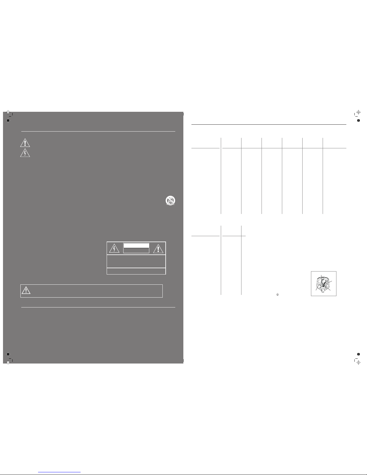
Mv-2 Mv-4 Mv-6 Mv-8 Mv-c Mv-ds
Recommended Amplifier
Enclosure
Bass/Mid Unit
Treble Unit
Effective Volume:
Frequency Response
Sensitivity SPL/M
Impedance
Minimum Impedance
Dimensions
Height on Feet
25 - 100W 25 - 125W 25 - 125W 25 - 200W 25 - 150W 25 - 100W
2-way reflex 2-way reflex 2-way reflex 2-way reflex 2-way sealed 2-way sealed
115 mm 150 mm 150 mm 2 x 150 mm 2x 115 mm 115 mm
25mm 25mm 25mm 25mm 25mm 25mm
4.3 litres 9.3litres 14.5 litres 26 litres 6 litres 2.4 litres
±6dB 56 Hz - 20 kHz 45 Hz - 20 kHz 40 Hz - 20 kHz 35 Hz - 20 kHz 85 Hz - 20 kHz 70 Hz - 20 kHz
@ 2.83V 86 dB 88 dB 89 dB 91 dB 91 dB 86dB
8 Ohms 8 Ohms 8 Ohms 8 Ohms 8 Ohms 8 Ohms
compatible compatible compatible compatible compatible compatible
5 Ohms 5 Ohms 5 Ohms 4.6 Ohms 5 Ohms 5.6 Ohms
(HxWxD):mm 220x140x205 295x188x290 840x188x290 915x188x290 150x460x170 220x140x115
mm 865 940
Specifications
Warning: Whenan amplifier is driven beyond its power output capabilities it will produce distorted results which will quickly damage your speakersby overheating.
Make surethat your amplifieris not left unattendedwhen playing, for exampleat parties, and turnthe volume control downat the firstsign of audible distortion.Playing
musicat extremely highvolumes forextended periods canpermanently damageyour hearing.
Mv-as
Recommended Amplifier:
Enclosure:
Effective Volume:
Frequency Response
Input Sensitivity
Input Impedance
Avg. max output
Bass Unit
Dimensions
Height on Feet
Integrated 100W
amplifier
reflex
20 litres
: 38 Hz - 120 Hz
: 250mv for 100W
10k Ohms
(1 metre) 107 dB
250mm
(HxWxD):mm 300x 300x330
mm 340
The power cord on your subwoofer may be supplied with a plug incorporating a
fuse, the value of which is indicated on the pin face of the plug. Should the fuse
need to be replaced, an ASTAor BSI approved BS1362 fuse must be used of the
same rating. If the plug is cut off it must NOT be re-used. Dispose of any such
plug safely. There is a danger of electric shock if a cut-off plug is inserted into a
mains socket.
The wires in the mains lead are coloured in accordance with the following code:
Green and Yellow- Earth: Blue - Neutral: Brown- Live.
As the colours of the wires in the mains lead may not correspond with the
markings identifying the terminals in the replacement mains plug, proceed as
follows:
The wire coloured Blue must be connected to the
terminal marked with the letter ‘N’ or coloured Black.
The wire coloured Brown must be connected to the
terminal marked with the letter ‘L’ or coloured Red.
The wire coloured Green and Yellowmust be
connected to the terminal marked with the letter ‘E’,or
coloured Green, or Green and Yellow,or marked with
the Earth symbol
LIVE
(BROWN)
NEUTRAL
(BLUE)
EARTH (GREEN/YELLOW)
FUSE
Note for UK Customers
Mission reserves the right to change all specifications without notice.E&OE
11
Page 3

Troubleshooting
Television picture colour is distorted
Subwoofer too close to TV. (Switch off system and TV. Move units away. Leave 15 mins. Switch on.
Excessive bass distortion at low volumes
Subwoofer level set too high; LFE level set too high; Subwoofer incorrectly wired
Excessive or distorted bass at high levels
System level set too high; Bass control set too high; Speakers too close to room corners
Popping or thumping from the subwoofer
System level set high; Subwoofer level set too high; LFE level set too high
Indistinct sound; Poor localisation of
effects. Poor localisation of dialogue
One or more loudspeakers is out of phase. Check all system connections and rectify.
(Read the manual for correct connection procedure)
Distorted / rattling sounds at high levels
System level too high; Objects on speakers/subwoofer; Objects too close to subwoofer
Sound lacks bass content
Bass reproduction indistinct
Front loudspeakers out of phase. Check all system connections and rectify.
Subwoofer not switched on; Subwoofer phase incorrect; Subwoofer crossover control too low
No Sound
System not switched on; Speaker cables shorting terminals out; Wrong source selected
Symptom Possible Cause
Before investigatinga problem,alwaysswitchoff thesystem at themains.
Loudspeaker Maintenance
Use a slightly dampened cloth to clean your cabinets and occasionally, a very light spray polish to protect their sheen. If necessary
clean grillescarefully witha soft brush.Subwoofers shouldonly everbe cleaned witha softdr ycloth.
Never touchthe loudspeakerdrive units asthey canbe damaged byimproper handling.
Product Service
Should a faultoccur with your loudspeakers pleasereturn them as a pair, even if only oneunit appears to be faulty. Please pack them
correctly,using theoriginal packing.
Product forservice should be returnedto the appointeddealer from whomyou purchased the product. If you experiencedif ficultiesor
there isno Missiondealer in yourarea, contactthe Mission distributorfor yourcountry or theMain ServiceCentre for yourregion.
International AudioGroup
Unit4, St Margaret’s Way,
Stukeley MeadowsIndustrial Estate
Huntingdon, Cambs, PE29 6EB
Tel:+44 (0)1480 447700 Fax: +44 (0)1480 431767
IAG. Room 2310 - 2311, Press Building, Shennan Road C,
Shenzhen, China.
Tel: +86-755-82091200 Fax: +86-755-82091205
IAG America, Inc. 8440 154th Avenue NE,
Redmond, Washington 98052 USA
Tel: +1 425 861 3909 Fax: +1 425 861 390
Authorised ServiceCentres
UK
ASIA
USA
10
Welcome to Mission
General Information
Unpacking Your Loudspeakers
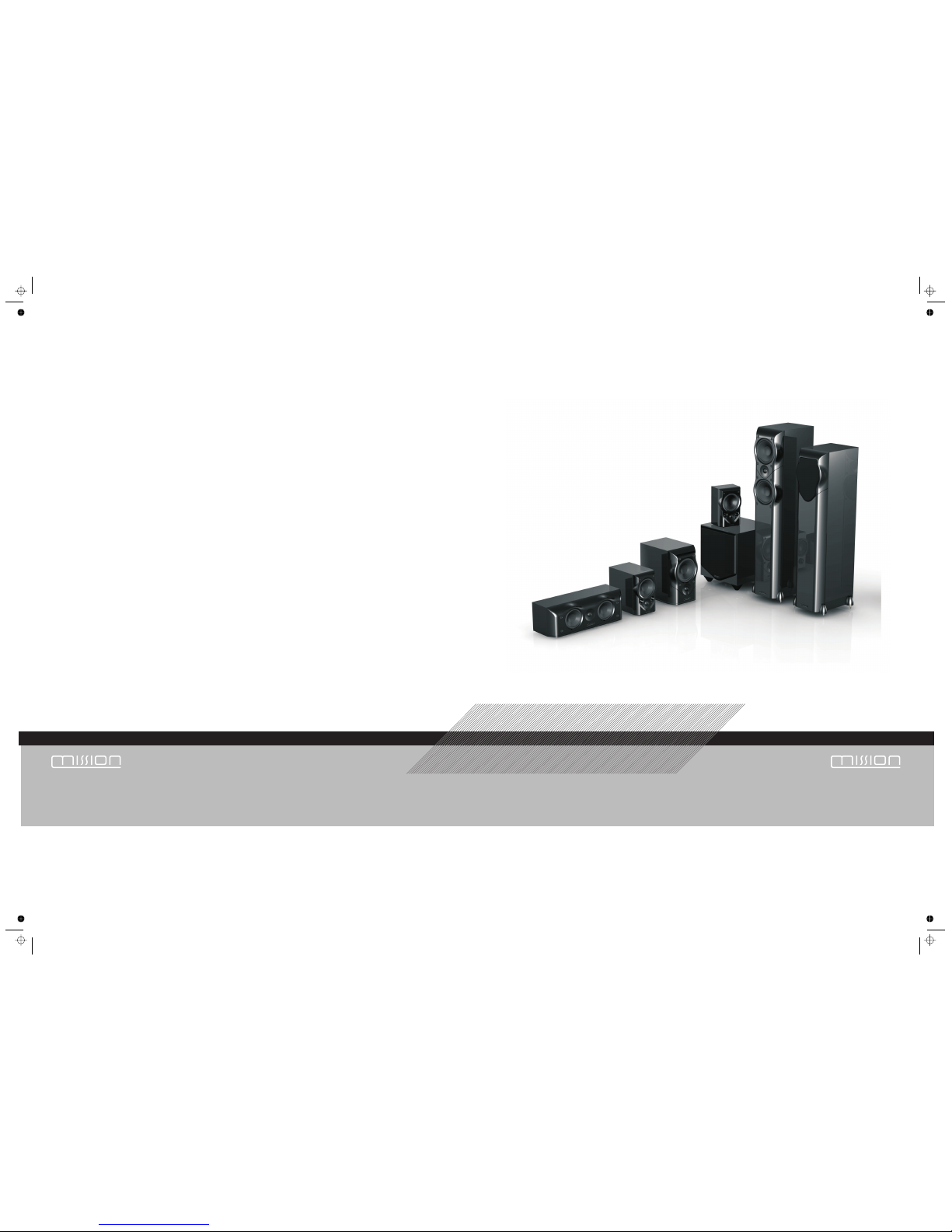
The series is the latest in a long line of distinguished Mission loudspeakers. These technologically advanced loudspeakers will
complement the finest electronics and décor. ass drivers tweeters are used throughout the range.
binding posts feature on all models. Your Mission loudspeakers will bring you great listening
pleasure for many years.
Mv
Mv
Robust b and precision silk
Screw fastening tri-lobe multi-way
Please read these instructions carefully before installing your loudspeakers. A few minutes studying this manual will ensure
superb performance from your loudspeaker for many years.
Please pay attention to all cautions printed on the pages marked with this symbol.
•
•
•
Carefully unpack each loudspeaker.
Retain all the packing materials so that your loudspeaker can be repacked and shipped without damage.
If you dispose of the packing,do so with regard to all recycling provisions in your area.
Warning: Becareful. Loudspeaker spikes are very sharp.
When positioning the speakers avoid piercing any electrical cables.
The and loudspeakers are supplied with the spike retainers fitted to the plinth but you will need to fit the spikes
• Mv-6 Mv-8
Fitting Spikes
Fitting the Spikes
Adjusting the Spikes
•
•
•
•
•
•
•
•
•
•
Invert the loudspeaker and place the top on a soft stable surface, or place the
loudspeakers on a towel or soft cloth to protect the surface.
Screw a nut fully on to each spike but ensure the nut is not tight.
Place a washer over the spike retainer.
Screw a spike half way into each spike retainer fitted in the base of the cabinet.
Tighten the nut finger tight onto the spike retainer.
Carefully return the loudspeaker to its normal position.
Ensure that spikes do not pierce cables etc. under the carpet.
Loosen each collar slightly.
Adjust the height by screwing in or out one or more of the spikes
until the loudspeaker is stable and level.
Tighten the nut fully tight onto the spike retainer.
Warning:
Never drag a loudspeaker. W lift them clear of the floor and replace them carefully
The and loudspeakers are heavy.
Always get someone to help you to lift and manoeuvre the loudspeakers.
hen moving loudspeakers
Mv-6 Mv-8
3
Page 4
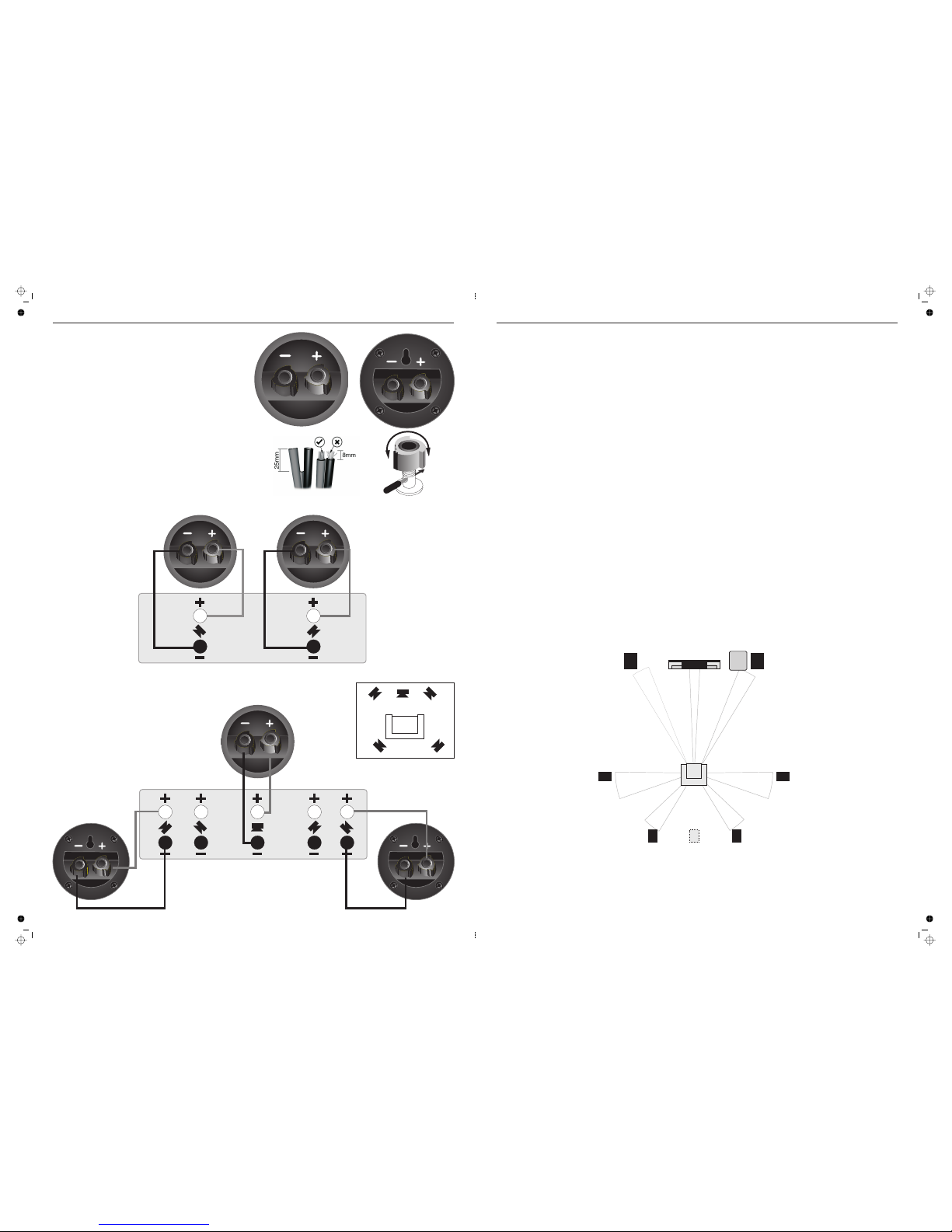
Connecting Your Loudspeakers
The seriesMv
Mv-ds
uses two-way tri-lobe binding posts.
The has a keyhole slot built into the terminal
panel for easy attachment to a wall.
All the other models use the terminal panel shown
at the left.
Unscrew each terminal. Thread the bare end of the
cable through the cross-hole ensuring there are no
loose strands. Tighten securely.
Connect the red, positive (+) terminal of the Left
loudspeaker to the corresponding red, positive (+)
amplifier terminal. Connect the black, negative (-)
terminals similarly. Repeat for the Right Channel.
LEFT SURROUND
RIGHT SURROUND
CENTRE
Connecting
Effects Loudspeakers
Stereo Connections
RIGHT
SPEAKER
LEFT
SPEAKER
Speaker Connections
4
Low Pass Filter:
Low-level Listening
Testingthe system
The subwoofer crossoverpoint should be set havingregard to the size andlow frequency extension of themain speakers. The role of
the subwoofer is to extend the bass response of the system, not to increase the overall bass level. If the loudspeakers are large the
crossover shouldbe set low,a value around55 Hz is agood place tostart. With smaller speakersthis can be increased,up to 85Hzfor
the smallbookshelf units.As always thefinal valueis determined bylistening.
Our ears are far more sensitive to midrange frequencies (2-5 kHz) than bass frequencies. Very low bass and especially percussive
bass is‘felt’ rather than heard.At low sound levelsbass frequencies appear toattenuate faster than midrangeand treble. As the level
increases this bass roll-off decreases. Occasionally we may wish to listen to a normally loud piece of music at a low level but with
retention ofthe bassinformation.
The simplestway to testthe system isto play,at a moderatelevel, music withdeep consistent bass.Switching the subwooferon and off
should cause change of the depth of bass, and the ambience will also alter. If there is a significant change in bass volume, or a
noticeable step in the bass response, or an increase in coloration when the subwoofer is playing, the setup needs to be refined. By
selecting differentcrossover andvolume settings, youwill beable readily toidentify themost favourable combination.
6.1 and7.1 Multichannel Reproduction
If your processor/amplifier combination features 6.1 or 7.1 operation, you can easily extend the system by purchasing an additional
pair of loudspeakers for the rear channels.
If your processor has 6.1 capability only, using a pair of spaced loudspeakers for the back channels and connecting them in
parallel to the back channel of your processor will offer a significant audible improvement. If you wish to do this, please consult the
specifications of your A/V amplifier to determine that this connection is feasible. The specifications for the are at the rear of
this manual. If you are in any doubt, use a single loudspeaker or consult your dealer
Mv-ds
Mv-ds
.
Stereo Reproduction
Left Surround
Left Back
90º
110º
135º
150º
22º
30º
LFE
Centre
Right Back
Right Surround
Right Front
Left Front
Dolby Labs Recommended 7.1 Placement
(Single Back channel for 6.1
9
Page 5

!
!
!
!
!
!
Set the subwoofer power switch to OFF.
Turn the system VolumeControl to minimum.
Re-check all system connections.
Connect the supplied subwoofer power lead to the IEC power socket on the subwoofer and connect the mains plug into the
wall socket.
Set the subwoofer volume control midway (12o'clock)
Switch on the mains power.
Switch on the subwoofer power switch. Check that the power indicator on the front of the cabinet glows. Now switch on the
system. Play a programme with extended bass and set the system volume to a reasonable level. Adjust the subwoofer volume
control to produce the desired level of bass.
If the bass is indistinct or lacks depth, the Phase switch may need adjustment. Set the switch to 0º and listen
carefully to some music with extended bass. If there is insufficient bass output from the sub-woofer set the Phase switch to 180º.
Select the position which produces the most natural, extended bass.
This adjusts the blend between the subwoofer and the main speakers. and enables the system to be set up
for optimum bass performance. The higher settings are for use with bookshelf loudspeakers, the lower settings for large
floorstanding models. If you choose too low a setting with small speakers, there will be a ‘hole’ in the bass response; too high a
setting with large speakers will result in the upper bass becoming bloated.
In normal mode the subwoofer is permanently on. This may result in low level hum or noise if the rest of the
system is switched off and the subwoofer is left switched on. Setting the AUTO switch to ON automatically turns the subwoofer on
when a signal is detected at any of the inputs and turns it off (Standby Mode) after a period of inactivity. We recommend the AUTO
switch be set to ON for normal operation.
In AUTO mode the indicator on the front of the subwoofer will glow RED when the unit is in Standby and GREEN when operational.
If your subwoofer is disconnected from the mains or the Power switch is “Off”, the indicator will be extinguished.
When the system is not in use for extended periods, we suggest you switch off the subwoofer to protect it from switching noises.
As the ear is unable to detect the direction from which deep bass originates, this allows freedom in positioning the subwoofer.
Varying the distance from the wall alters the amount of bass. Some prefer to place the subwoofer against a room corner. This
arrangement gives more bass at the possible expense of clarity.
Many digital AV processors require you to specify the size of speakers in the various channels. These are
usually ‘Large’ or ‘Small’. We recommend that you set the centre and surround speakers to 'Small'. This will direct all the bass in the
system to the subwoofer and provide clean, deep and louder bass. Set the ‘Subwoofer’ option on the processor to 'On’ or 'Yes'.
Set the and to ‘small’. If you are using a digital AV processor the subwoofer crossover setting should be 85Hz.
Set the and to ‘large’. The may be optionally set to ‘small’. In this case the subwoofer crossover setting should be
55Hz. If you find the bass excessive, set the loudspeaker to ‘large’.
Once the loudspeaker settings have been finalised, put the AV amplifier into its “Test” mode (see your processor instructions),
Adjust the levels until all channels are equally loud.
You may need to adjust the subwoofer output level. Avoid setting too high a level or you will swamp the sound with bass which be
tiring to listen to and may limit the subwoofer’s ability to respond to large bass transients. Set a sensible level going into the
subwoofer. The subwoofer volume control should be between 12 o’clock and 3 o’clock .
If all the speakers are set to ‘Small’, the LFE channel will be combined with the bass from other channels and all this feeds into
the subwoofer. When you set the LFE level from your AVprocessor, use care with this setting as the LFE channel may contain
powerful low frequencies which, although normal in a cinema, may overload a domestic subwoofer.
If, during a programme, you hear popping or thumping noises coming from the subwoofer, immediately turn the AVProcessor's
volume level down and then back off the LFE level. If this does not cure the problem, back off the volume level at the subwoofer.
Please read the relevant sections of your AV amplifier manual and familiarise yourself with the various issues. If you are unsure,
consult your dealer for help.
Fine Tuning
Setting Levels
PHASE SWITCH:
LOW PASS FILTER:
AUTO SWITCH:
LOUDSPEAKER SIZES:
Subwoofer Settings for Mv Front Loudspeakers
LFE:
Home Theatre Topics
Mv-2 Mv-4
Mv-6 Mv-8 Mv-6
Setting Up Your Subwoofer
8
Positioning Your Loudspeakers
Mission and loudspeakers should be placed on the floor
(ideally on spikes). Mission should be mounted on rigid
stands, ideally spike coupled to the floor.
Height is important: a stand should place the top of a speaker at ear
level to a seated listener. Shelf or bracket mounting is second best. The
distance from the wall can profoundly affect loudspeakers' sonic
performance. If your speakers are too close to the wall the bass will
boom and sound coloured. Moving them into the room may increase
clarity but tends to reduce bass output. When positioned correctly, the
high frequency response is smooth with well-defined, powerful bass.
Start with the speakers about 300mm from the wall and 1.8 metres
apart. The distance from each loudspeaker to the side wall should be
at least 500mm. Vary the distance between the two loudspeakers and
the distance from the wall until you get a perfect stereo stage.
If your loudspeakers are wired correctly, the sound should be full with clean treble and a deep, rich bass.
Mv-6 Mv-8
Mv-2 Mv-4and
>0.2m
>0.5m
>0.5m
1.5- 3.0m
Your Centre loudspeaker should be sited the TV monitor, or
on a shelf in a console below the TV set. If you place the unit on top of
the TV, ensure the cabinet can stand the weight and the is
stable. your TV or your TV dealer if you are in doubt.
Connections: Connect the to the Centre loudspeaker terminals of
your AV amplifier
Mv-c
Mv-c
above
speaker
Consult manual
following the instructions in the previous section.
To wall mount the speakers: Ensure the wall is sound, free of
obstructions and capable of supporting the loudspeaker plus some
pulling force. You will need 2 wall fixings and 2 No. 8 Round Head
screws to suit your wall for each loudspeaker.
Connect each loudspeaker before you start.
Determine the height of the loudspeaker. Mark off a
horizontal line with two fixing centres at 236mm. Drill
and plug the holes. Screw a No.8 screw into each hole
leaving 7mm protruding. Connect the connecting wire
to the loudspeaker but do not connect the cable to the
amplifier. Lift the loudspeaker up to the mounting
position. Align the keyhole slots over the screw heads
and gently pull down until the speaker is secure.
The Mission Centre Channel SpeakerMv-c
The is designed for wall mounting.
Now connect the to the Rear loudspeaker terminals of your AV amplifier
ollow the instructions in the previous section
Mv-ds
Mv-ds
f ing .
Place the speakers behind the
listening seat above head height 2-4 metres apart as indicated in the diagram.
You will need one wall fixing and one No. 8
Round Head screw per loudspeaker. Mark and drill one fixing hole. Connect
the connecting wire to the loudspeaker but do not connect the cable to the
amplifier. Attach the loudspeaker as shown above.
To wall mount the speaker:
The Mission Surround SpeakerMv-ds
5
6.0mm
b
7mm
No 8 x 40mm
d
c
f
236.0mm
e
Caution! Wall mounting should be carried out by qualified licensed sound contractors or technicians. All installation and
wiring shouldcomply withrelevant standards laiddown bythe competentauthority in thecountry and placeof installation.
Page 6

The Mission Powered SubwooferMv-as
b
c
d
e
f
g
h
i
j
1)
b
c
d
f
e
g
h
i
j
1)
Phase Control
Speaker Level Inputs
Line Level Outputs
Line Level Inputs
Volume Control
Crossover Frequency Control
Auto Power Switch
Power ON/OFF Switch
IEC Mains Input Socket
Mains Power Fuse
Preliminaries
Power Connections
Open the carton and remove all the top
packing pieces. Lift the subwoofer out
carefully. DO NOT lift the subwoofer out
of the carton using the protective bag.
The unit is heavy; if you cannot
manage it easily, get assistance.
Retain the packing materials. If you
decide not to keep the packing, please
dispose of it having regard to any
recycling regulations in your area.
Please retain the user manual. If you
transfer this equipment to a third party,
please ensure all the instructions are
passed on with the product.
This subwoofer is factory set to operate
from the mains voltage marked on the
amplifier panel. Before connecting
check this voltage is correct for your
mains supply.
230 volt products - 220 V to 240 V
115 volt products - 110 Vs to 120 V
If you move to an area with a different
mains supply, consult your dealer for
advice.
!
!
Placement
There should be a mains outlet within easy reach.
Although the unit may be placed almost anywhere in the room, even behind the sofa or the TV set, we recommend that it be
placed in front of the listener and as central to the listening position as possible. The subwoofer should not be operated within
450mm of a television set as the drive unit magnet may distort the picture.
We suggest you position the subwoofer about 20cm (8 inches) from the wall. A position close to the wall will enhance the bass;
placing it across a room corner will increase the bass further, possibly at the expense of clarity.Experiment with a variety of
locations and sources before making a final decision.
The bass port is mounted under the subwoofer firing downward and moves a lot of air at high volume, so make sure the floor is
sound. The subwoofer is front-firing so do not place it behind surfaces or objects that may rattle.
Your system will perform best if there is a clear line of sight between the subwoofer and the listening position.
NOTE: When running signal cables to the subwoofer, keep them clear of obstructions. Do not run a long signal cable close to mains
cables or cables carrying heavy digital traffic.
6
A/V Processor Connections
Stereo Line Output Connections
Pre Out - Main In Connections
Speaker Level Connections
Your subwoofer has been designed for optimum
performance with a Digital processor. If your AVprocessor
has a line level or LFE subwoofer output you should use this
connection. You will need to purchase a single screened
RCA phono lead from your dealer. Connect this lead to the
Left line input of the Subwoofer as shown below
Alternatively, you may use a split mono lead from the
processor to both inputs of the subwoofer. In this case the
input level at the subwoofer will be slightly higher.
If your amplifier has a spare preamplifier output or a stereo
sub-woofer output, connect the sub-woofer as shown. You
will need a stereo screened RCA phono cable.
If you use a stereo pre and power amplifier, or a stereo
amplifier where the pre and main amplifier can be
separated, connect the sub-woofer as shown. You will
need two screened RCA ‘Y’ adaptors and two single RCA
phono cables.
Remove the Pre-Main links on your amplifier. Connect the
RCA ‘Y’ adaptors and cables as shown. Connect one leg of
the ‘Y’ adaptor to the Left Channel Pre Out socket on the
amplifier and the other leg to the Left Channel Main In
socket. Connect the remaining plug on this combination to
the Left Channel Line Level Input on the sub-woofer. Repeat
this for the Right Channel.
The high level Speaker connections should be used only if
your amplifier does not have a line level subwoofer output.
In this connection the subwoofer is fed together with the
Front loudspeakers. For this you will need two extra twin
core cables.
Measure out two loudspeaker cables of the appropriate
length. Prepare the cables as described on Page 4
Connect the Left Speaker Terminals on the subwoofer to the
Front Left speaker terminals on the amplifier. Connect the
Red (+) speaker terminal on the amplifier to the Red (+)
terminal on the subwoofer. Connect the Black (-) speaker
terminal on the amplifier to the Black (-) terminal on the
subwoofer. Now connect the Right Speaker terminals on the
subwoofer to the Front Right speaker terminals of the
amplifier.
.
CENTRE FRONTREAR
LEFTLEFT RIGHTRIGHT
Subwoofer Out (Line Level)
AV AMPLIFIER
CENTRE FRONTREAR
LEFTLEFT RIGHTRIGHT
LEFTRIGHT
AMPLIFIER
L
R
PRE
OUT
MAIN
IN
(x2)
CENTRE FRONTREAR
LEFTLEFT RIGHTRIGHT
L
R
AV AMPLIFIER
Stereo Outputs (Line Level)
LEFT
FRONT RIGHT
FRONT LEFT
SUBWOOFER
RIGHT
7
 Loading...