


M110/M800
Installation Manual

2
Welcome,
Thank you for choosing Mission Communications for your monitoring and alarm needs!
Mission is committed to providing the highest quality in SCADA solutions. All of our
products go through a strict testing regimen before leaving our facility to ensure a
seamless “out of the box” installation experience.
The rst chapters of this manual focus on pre-installation and are intended to identify
issues and recommend solutions to optimize your installation. Appendix A houses
descriptions of terminology that is used throughout the manual. Please consider the
steps in these sections and conrm that you have received all the necessary parts for a
successful installation.
Each RTU is packaged with an RTU Setup Form along with a User Guide, Terms &
Guarantees, and an Emergency notice label. New customers will also be given a New
Customer Packet which includes Account and Notication Setup Forms, along with
electronic (Dallas) Key instructions. Prior to installation, please complete and send in
all forms to Mission technical support in order to access your web portal with the login
credentials you have provided.
Mission provides customers with 24-hour access to our technical support team.
Additionally, we provide a wide range of information that can be remotely accessed
through the web portal. Here at Mission, it is our goal to provide customers with the
latest technology and designs while ensuring great value.
Weekly training webinars are available most Wednesdays at 2:00 P.M., Eastern. We also
provide quarterly newsletters and training videos on our website. We encourage you and
your staff to take advantage of these resources. Visit www.123mc.com to sign up for the
webinar, to nd our training videos, and newsletter archives. Our technical support staff
is available at (877) 993-1911, option 2 for further assistance.
Thank you,
The Mission Team
WARNING: This symbol indicates there is caution or warning to avoid damage
to your property or product.
WARNING: Follow requirements for eld wiring installation and grounding as
described in NEC and your local/state electrical codes.
NOTE: This symbol indicates that there is something that requires your special
attention.
This device complies with part 15 of the FFC Rules. Operation is subject to the following two condi-
tions: (1) This device may not cause harmful interference, and (2) this device must accept any
interference received, including interference that may cause undesired operation.

3
Contents
Chapter 1: Overview ....................................................................................... 5
M110/M800 At A Glance
Enclosures
Included Hardware with the Standard RTU
Recommended Tools
Materials
Chapter 2: Site Survey and Connectivity Test ............................................. 7
Chapter 3: Antenna Installation .................................................................... 9
Antenna Best Practices
Chapter 4: RTU Installation and Wiring ........................................................10
Chapter 5: RTU Startup ..................................................................................16
Chapter 6: Test the Installation .....................................................................18
Chapter 7: Site Commissioning ....................................................................20
Appendix A – Terminology ............................................................................21
Appendix B – Solid State Relay Wiring Diagram .........................................23
Appendix C – Wiring Relays to Digital Inputs Using a Common Wire .....24
Appendix D – Detailed RTU Boot-up Sequence .........................................25
Appendix E – Troubleshooting ......................................................................26
Installation Notes ...........................................................................................27
Mission offers a variety of related documents. Scan the QR code
with your smartphone or visit www.123mc.com/literature.asp to
view.

4
5
Chapter 1: Overview
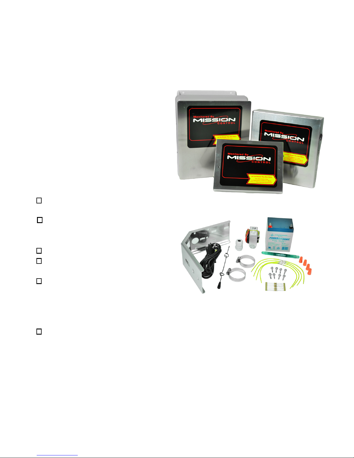
M110/M800 at a Glance
Each RTU is packaged with everything
needed for a standard installation.
Enclosures
NEMA 1 - indoor mounting
NEMA 4 - outdoor mounting
Flatpak - control panel or cabinet
mounting
Included Hardware with a
Standard RTU:
RTU (NEMA 1, NEMA 4,
or Flatpak enclosure)
RTU Installation Packet
(RTU Form, User Guide, and
Emergency notice label)
Battery - 12 V, 5 Ah
Flying Lead Transformer (120
VAC to 12 VAC, 1.2 amp)
Universal Mount Antenna
Kit (11’ RG58 cable with
SMA-M connector, pole, or
wall mount bracket, dual band antenna whip, (2) pole clamps, and
(2) Metal oxide varistors (MOVs) rated for 120 V control circuits)
Accessory Bag ((4)1K ohm long yellow EOL resistors, (8)
1K ohm EOL resistors, (4) wire nuts, (8) screws, and
an interchangeable Phillips/athead screwdriver)
New customers will also be given a New Customer Packet
which includes Account and Notication Setup Forms, along with (5)
electronic (Dallas) keys plus instructions and Manage SCADA document.
Note: If there are any missing parts, please contact us.
NEMA 1
NEMA 4
Flatpak
6
Mission offers a variety of optional accessories. Scan the QR
code with your smartphone or visit www.123mc.com/accessories
to view our accessories catalog.
Recommended Tools (not included)
Mechanical Electrical
Drill motor Voltmeter/multimeter
Step drill or hole saw Wire cutters
Hack/reciprocating saw Wire strippers
Metal cutting blades
Pliers
5/16” nut driver or tip
Screwdriver phillips head
Ladder (for antenna mounting if
necessary)
Materials
18 or 22 gauge wire, 2, 4 or 8 conductor stranded and shielded
10-14 gauge green wire (follow NEC standards) for grounding the RTU
¾” Flex conduit with straight and elbow ttings
Uni-strut rail and hardware for mounting
Interposing relays and bases (if no dry contacts are available)
12 VDC coil interposing relay (if output relays will be used)
Sealant
7
Chapter 2: Site Survey & Connectivity Test
Prior to installation, please complete and submit the RTU Installation Form via fax (770685-7913) or email (setupforms@123mc.com) so Mission can set up the new unit(s)
on your web portal. New customers must also complete and submit both forms within
the New Customer Packet. The web portal can be accessed with the login credentials
you provided within the Account Setup Form. Once completed and entered by technical
support, alarms can be enabled for your RTU(s) immediately after installation so you can
perform end-to-end testing.
By powering the RTU and testing connectivity before mounting the hardware, you can
optimize the signal strength for years of trouble-free communication. The test only takes
a few minutes since the included battery can provide temporary power. Refer to the
antenna best practices section (chapter 3) when positioning the antenna.
1. Remove the RTU from the box and place it on or near the control panel it will be
monitoring. Remove the antenna cable and antenna whip from the package and
hand-tighten the SMA-M connector to the radio SMA-F connection on the RTU
(see Figure 1).
2. Screw the whip antenna onto the molded antenna base and
place it outside as high as possible. Hand-tighten plus ¼
turn with a wrench. Do not over tighten.
3. Power the RTU with the 12 VDC battery (see Figure 1).
Connect the negative (black) lead to the battery and then
connect the positive (red) lead. LEDs will illuminate in a
sequence (see Figure 1 for LEDs). Once the sequence
is completed, you will hear 3 beeps from the buzzer. This
indicates the unit has connected to Mission servers. If the
RTU does not connect after two attempts, refer to
Appendix D: RTU Boot-up Sequence, Appendix E:
Troubleshooting or call technical support.
4. The signal strength push button is located to the left of the vertical stack, below the
radio (see Figure 1). Press the button once to see the vertical LED stack display
signal strength with the corresponding dBm readings to the right of the LED’s.
Once the button is pressed it will turn off for ~6 seconds then it will show the signal
strength of area. The LED’s will give live reading for two minutes then go back to
operational mode. Press button again to repeat test. You can also check signal
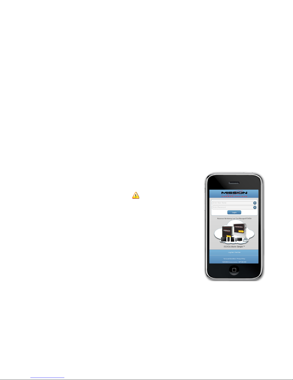
strength by logging into your web portal by visiting www.123mc.mobi on your smart
device. Select “status” page and pick the RTU you are installing then page for signal
strength. A -75dBm signal is better than a -100dBm signal, although it is acceptable.

8
Main Printed Circuit Board Wired for Site Survey
Figure 1
9
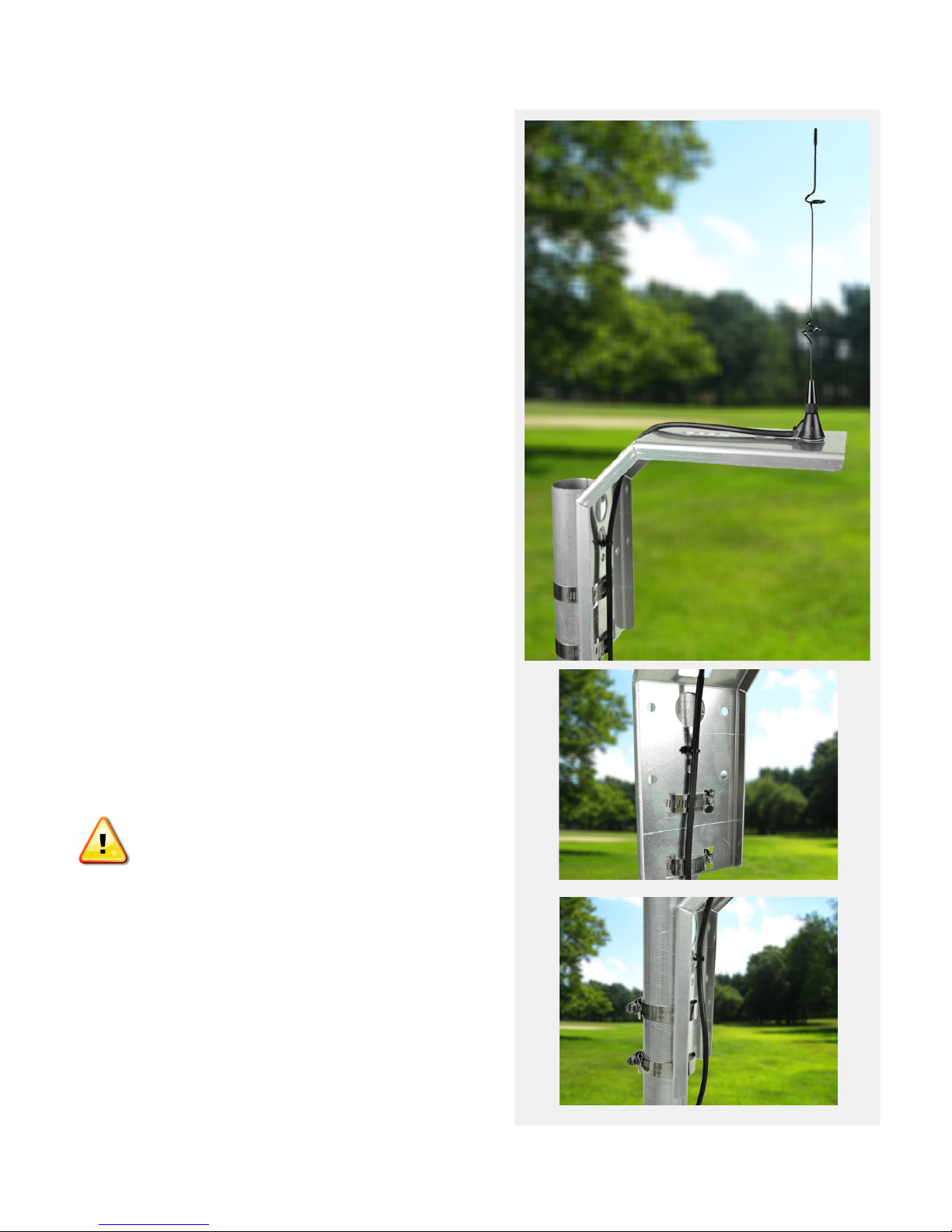
Chapter 3: Antenna
Installation
Overview
The antenna should be mounted outdoors
and above other objects. By optimizing the
placement of the antenna, you increase the
chances that the radio can communicate
with more than one cell tower. The coaxial
cable should reach the Mission RTU radio
connection with no severe routing of the
coax. Consider where the RTU will be
mounted in relation to the location of the
antenna.
1. Install the antenna cable and antenna
whip. Connect the SMA-M cable connector
to the SMA-F connector on the main board
(see Figure 1). Unscrew the nut from the
molded antenna base. Feed the molded
antenna base through the square cut out
on the bracket. Place the molded antenna
base in the circle cutout.
Secure the molded antenna base
to the bracket with the nut. Handtighten the nut, plus ¼ turn with a
wrench. Do not overtighten.
2. Install the mounting bracket. Mount
the Universal Antenna Mount directly on the
face of a at surface or a metal pipe using
the included pipe clamps (placing above
any obstructions).
1. bjh
 Loading...