


HANDHELD WIRELESS MICROPHONE
HANDHELD WIRELESS MICROPHONE
1. PARTS NAME AND FUNCTIONS
1 2 3 4 5 6 7 98
(Fig.1)
1. Grille: Protects cartridge, prevents "POP" noise and prevents microphone
from rolling with polygonal shape.
2. Color Ring: For frequency differentiation.
3. Battery Status Indicator: Indicates power on / off and the battery status.
When the power switch is turned ON, the red LEDs indicator flashes
briefly, indicating normal battery status. If no flash occurs, it has either no
battery or the battery is discharged or installed incorrectly. If after power
on the indicator stays lighted, it warns that the battery is weak and should
be replaced.
4. Power On-off Switch: Slide the switch for power " ON " or " OFF ".
5. Housing: Upper portion to be connected to capsule module and battery.
Internally, it holds transmitter PCB.
6. Battery Compartment: Designed to accommodate two 1.5V(AA) batteries.
7. Battery Cap: Covers battery in the battery compartment.
8. Anti-roll Ring: For frequency differentiation.
9. Act Signal Receptor:
2. BATTERY INSERTION
(Fig.2)
1. Unscrew battery cap in a counter-clockwise direction (7).
2. Insert a 9V battery into the battery compartment according to the correct
polarity as shown in Fig.2. The moment the battery touches the terminals,
the indicator will flash briefly (7). This means the polarity is correct.
However, if no flash occurs, this indicates wrong insertion or that the
battery is dead. Please re-insert the battery according to its correct
polarity or exchange it for a fresh battery.
3. OPERATING INSTRUCTIONS
1. When microphone is switched on:
When the power is switched on, the indicator will flash briefly indicating
normal operation.
2. During Usage:
The AF LED indicator on the receiver will illuminate according to the
audio signal strength from the microphone.
3. When the microphone is not in use:
Make sure that you turn off the microphone after use to extend the
battery life. Remove the battery from the battery compartment if
microphone is not to be used again for some time. If a rechargeable
battery was used, take it out and recharge it.
14
4. CAUTIONS
Under normal operation, when microphone and transmitter are paired
together to set frequency, microphone indicator (3) will remain off after ACT
setup the frequency. However, if indicator (3) is flashing, it means microphone
and transmitter are not in the same frequency band. Please check the
stickers on transmitter and receiver to observe if they are sharing the same
frequency bands.
15
BELT PACK TRANSMITTER
BELT PACK TRANSMITTER
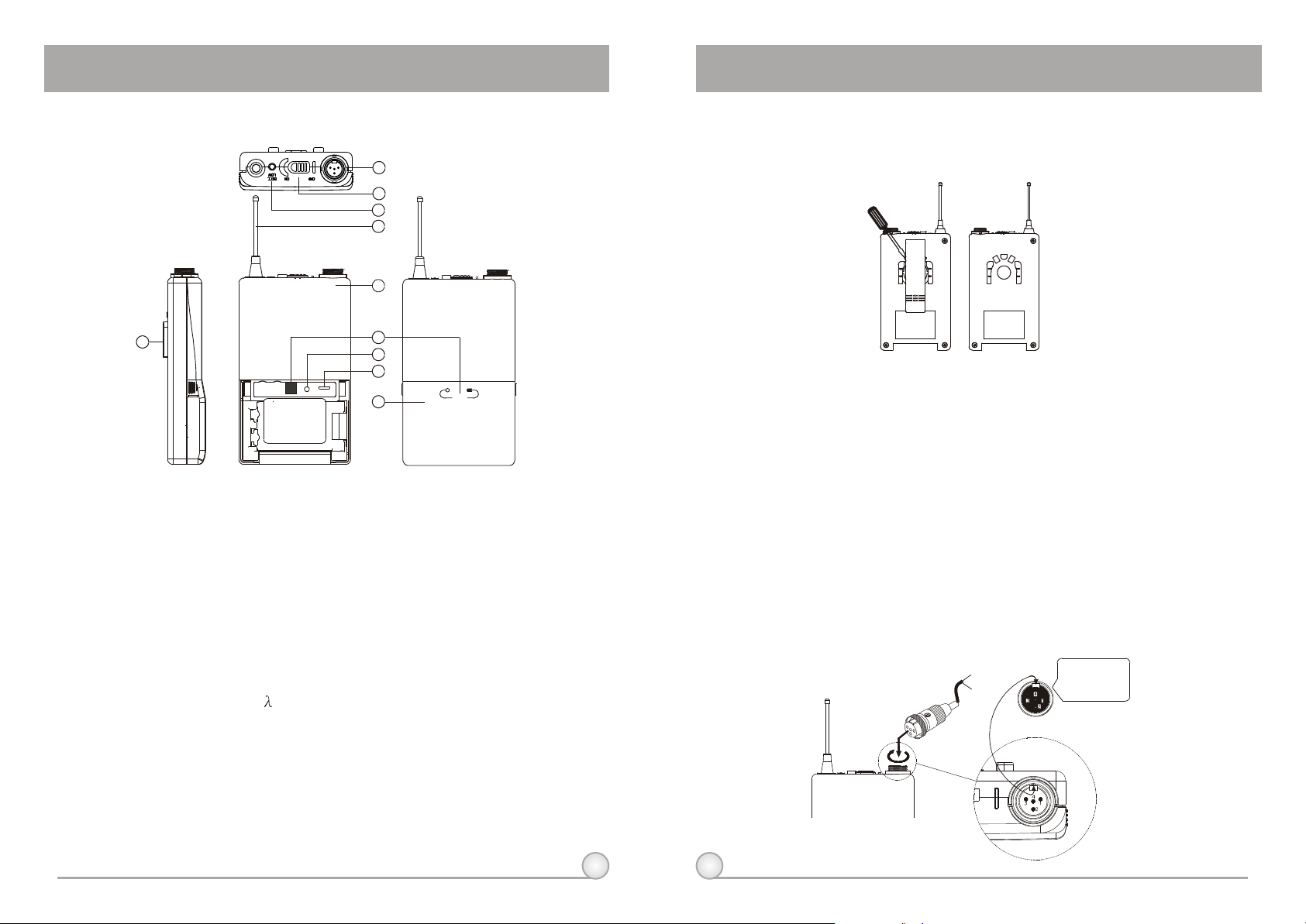
1. PARTS NAME AND FUNCTIONS
1
2
3
4
5
10
GAINGAIN MTMTGTGT
1. AF Input Jack: Connects to either lavaliere or headset microphone. (See 5
ways of connection on AF Input Connections)
2. Power Switch: Switch to ON position for operation. Switch to OFF position
when not in use.
3. Battery Status Indicator: Indicates the power on / off and battery status.
(a) When power switch is turned on: The LED indicator flashes briefly,
indicating normal battery status.
(b) When RED light illuminates at either power on or during usage: The
battery level is low, therefore, a new battery replacement is thus necessary.
4. Transmitting Antenna: 1/ 4 transmitting antenna.
5. Transmitter Housing: Packages the PCB and battery.
6. Act Signal Receptor
7. Gain Control: Adjusts the desirous input gain.
8. GT/MT Level Select Switch: Switch GT position for electric guitar usage and
"Line In". Gain Control is irrelevant for "GT". Switch to "MT" for condenser
microphone or wired microphone. Gain Control works in "MT" for input
sensitivity adjusting.
6
7
8
9
ACT
(Fig.1)
16
9. Battery Compartment and Cover: Accommodates two 1.5V(AA) batteries.
10.Detachable Belt Clip: Allows 360 degrees rotating to suit transmitting angles.
To detach simply use a screwdriver at a 45 degree angle to unfasten. see
diagram.
2. OPERATING INSTRUCTIONS
1. To adjust GT/MT Switch (8), and Gain Control (7), simply push down both
snap locks on the sides of battery cover and flip it backwards to expose the
adjustment panel.
2. Before power on, ascertain if same channelwas set up for both receiver and
microphone. If not adjust to same channel accordingly.
3. The LED indicator flashes briefly when power on indicating normal battery
status. If no flash occurs it has either no battery, the battery is drained or
installed incorrectly. Change accordingly.
4. Plug the microphone connector into the input jack (1) and tighten the
connector screw by clockwise direction as shown in (Fig. 2).
17
Capsule Connectort
Headset
Lavalier
Please aim of
the fillister
and insert the
connector
(Fig.2)

BELT PACK TRANSMITTER
BELT PACK TRANSMITTER
3. AF 4-PIN INPUT CONNECTION METHODS
(1) 2-Wire Electret condenser microphone Capsule
PIN
SHIELD
AUDIO
(2) 3-Wire Electret condenser microphone Capsule
SHIELD
AUDIO
BIAS
(3) Dynamic Microphone
2 1
3
SHIELD
AUDIO
PIN
1
2
3
4PIN
4
PLUG
PIN
1
2
3
4PIN
4
PLUG
1
2
3
4
4PIN
PLUG
4. BATTERY INSTALLATION
1. Pushing down both snap locks on the sides of battery cover to open battery
cover. Take out the batteries. Fig.(3).
2. Insert a 9V battery into the battery compartment according to the correct
polarity as shown in Fig. (4). Then push up to close the battery
compartment as shown in Fig. (4).
(Fig.4)(Fig.3)
(4) Electric Guitar
PIN
SHIELD
AUDIO
1
2
3
4PIN
4
PLUG
(5) Line-in (Impedance 8K ATT. 10dB)
PIN
SHIELD
AUDIO
1
2
3
4PIN
PLUG
4
18
5. CAUTIONS
Under normal operation, when microphone and transmitter are paired
together to set frequency, microphone indicator (3) will remain off after ACT
setup the frequency. However, if indicator (3) is flashing, it means microphone
and transmitter are not in the same frequency band. Please check the
stickers on transmitter and receiver to observe if they are sharing the same
frequency bands.
19

 Loading...