

Page 1
ACT-101 / MT-101 ACT
2 C E 3 3 6 A
WIRELESS IR REMOTE CONTROL SYSTEM
User Guide
MIPRO Electronics Co., Ltd.
Headquarters: 814 Pei-Kang Road, Chiayi, 60096, Taiwan.
Web: www.mipro.com.tw
E-mail: mipro@mipro.com.tw
Design and specifications are subject to change without prior notice
AS110701
Page 2
! IMPORTANT SAFETY INSTRUCTIONS !
WARNING
1. Read these instructions.
2. Keep these instructions.
3. Heed all warnings.
4. Follow all instructions.
5. Do not use this apparatus near water.
6. Clean only with a dry cloth.
7. Do not block any ventilation openings. Install in accordance with the
manufacturer's instructions.
8. Do not install near any heat sources such as radiators, heat registers,
stoves, or other apparatus (including amplifiers) that produce heat.
9. Do not defeat the safety purpose of the polarised or ground plug: A
polarised plug has two blades with one wider than the other. The wide blade
is provided for your safety. When the provided plug does not fit into your
outlet, consult an electrician for replacement of the obsolete outlet.
10. Protect the power cord from being walked on or pinched particularly at plug,
convenience receptacles, and the point where they exit from the apparatus.
11. Only use attachments/accessories specified by the manufacturer.
12. Use only with a cart, stand, tripod, bracket, or table specified
by the manufacturer, or sold with the apparatus. When a cart
is used, use caution when moving the cart/apparatus
combination to avoid injury from tip-over.
13. Unplug this apparatus during lightning storms or when unused
for long periods of time.
14. Refer all servicing to qualified service personnel. Servicing is required
when the apparatus has been damaged in any way, such as power-supply
cord or plug is damaged, liquid has been spilled or objects have fallen into
the apparatus, the apparatus has been exposed to rain or moisture, does not
operate normally, or has been dropped.
15. To reduce the risk of fire or electric shock, do not expose this apparatus to
rain or moisture.
16. Apparatus should not be exposed to dripping or splashing and no objects
filled with liquids, should be placed on the apparatus.
17. Use only with the battery which specified by manufacturer.
18. The power supply cord set is to be the main disconnected device.
1. FOR OUTDOOR USE:
To reduce the risk of fire or electric shock, do not expose this apparatus to
rain or moisture.
2. UNDER WET LOCATION:
Apparatus should not be exposed to dripping or splashing and no objects
filled with liquids, such as vases should be placed on the apparatus.
3. SERVICE INSTRUCTIONS:
CAUTION - These servicing instructions are for use by qualified service
personnel only. To reduce the risk of electric shock, do not perform any
servicing other than that contained in the operating instructions unless you
are qualified to do so.
This symbol indicates that dangerous voltage constituting a risk of
electric shock is present within this unit.
This symbol indicates that there are important operating and
maintenance instructions in the literature accompanying this unit.
& IC - ID
THIS DEVICE COMPLIES WITH PART 15 OF THE FCC RULES AND RSS-123 ISSUE2 OF
CANADA. OPERATION IS SUBJECT TO THE FOLLOWING TWO CONDITIONS:
(1) This device may not cause interference.
(2) This device must accept any interference, including interference that may cause
undesired operation of the device. This equipment complies with FCC RF radiation
exposure limits set forth for an uncontrolled environment.
Disposal
200 5-08- 13
Dispose of any unusable devices or batteries responsibly and in accordance
with any applicable regulations.
Disposing of used batteries with domestic waste is to be avoided!
Batteries / NiCad cells often contain heavy metals such as cadmium(Cd),
mercury(Hg) and lead(Pb) that makes them unsuitable for disposal with
domestic waste. You may return spent batteries/ accumulators free of
charge to recycling centres or anywhere else batteries/accumulators are
sold.
By doing so, you contribute to the conservation of our environment!
Page 3

Contents
Wireless IR Remote Control Receiver
PRODUCT OVERVIEWWIRELESS IR REMOTE CONTROL SYSTEM
PRODUCT OVERVIEW
KEY FEATURE AND BENEFITS
PART NAMES AND FUNCTIONS--ACT-101
RECEIVER INSTALLATION
RACK-MOUNT RECEIVER INSTALLATION
OPERATION
PART NAMES AND FUNCTIONS--MT-101ACT
TIPS IN OPERATING INFRARED REMOTE CONTROL
OPERATING INSTRUCTIONS
CHARGING THE TRANSMITTER MICROPHONE
11
12
16
1
2
3
6
7
8
9
Thank you for choosing MIPRO wireless IR remote receiver system. Please read
this user guide thoroughly to ensure the system is operated correctly to
maintain optimal performance.
ACT-101 Included Accessories:
ACT-101 Receiver × 1
ACT-101 ACT Port Receiver × 1
Phone Jack Cable × 1 [6.3mm / 1/4”]
RJ-11 Network Cable × 1 [150cm / 5']
Receiver Antenna × 2
MT-101ACT Transmitter Microphone × 1
MP-101ACT Battery Charger & DC Power Adapter × 1
AC/DC Power Adapter × 1
User Guide × 1
0
1
Page 4
Wireless IR Remote Control ReceiverWireless IR Remote Control Receiver
KEY FEATURE AND BENEFITS (ACT-101 Receiver)
!
EIA standard single-channel in 19” 1/2-rack unit size.
!
97 UHF channels. Can be programmed, installed and used in up to 97 different rooms.
!
Diversity reception for extended and reliable transmission.
!
ACT technology automatically synchronizes frequency between transmitter and receiver.
!
Output level and dynamic range are accurately pre-adjusted to equal the microphone
capsule's sensitivity, thus ensuring optimal performance of the system.
!
Detachable 100~240V AC auto-switching power supply.
!
Ideal for teaching professionals and presenters in multiple classrooms, lecture halls and
similar environments.
KEY FEATURE AND BENEFITS
(MT-101ACT Wireless IR Remote-Control Transmitter)
!
Featuring Industry's only all-in-one, versatile MT-101ACT transmitter microphone.
!
Compact, ultra-lightweight design and powered via rechargeable or disposable alkaline
batteries.
!
Once programmed, Same MT-101ACT transmitter microphone can be used in up to 97
different rooms.
!
Power on/off and volume loudness can be wirelessly remote controlled.
!
MT-101ACT can be a handheld or worn as a neck lanyard for hands-free operation with
an external headset microphone.
!
Built-in 3.5mm(1/8”) mini-jack line-input accepts other audio sources
(CD/iPodMP3/tape/mini-disc/computer) for amplification.
!
Amazing 24 operating hours per fast charge.
PART NAMES AND FUNCTIONS
Front Display Panel
SIGNALACT
RF AF
1
1
ACT Port Indicator Switch: Red indicator does not illuminate when receiver is
2
3 4
plugged-in and pressed. Red indicator illuminates only when IR signal is received
successfully by the MT-101ACT remote transmitter microphone. Red indicator
illuminates denote receiver is now turned on
Note: This is not a power on & off switch. Always leave switch pressed upward. ACT
Port and MT-101ACT transmitter microphone cannot remote, function and use in
pressed downward position.
2
ACT Port:
Receive signal to turn on (and off) receiver and sync frequency to
transmitter.
3
RF Indicator: Indicates RF signal strengths from transmitter.
4
AF Indicator: Indicates audio signal strengths from transmitter.
5
EXTEND Socket: RJ-11 network cable connection to an external receiver for an
improved IR signal reception. Switch to EXTEND if connected.
6
IR MODE: To improve IR signal reception for ACT port. Factory preset at BUILT-IN.
Switch to EXTEND if connected externally.
IR MODE
EXTEND BUILT-IN
5
6
ACT-101
Wireless Receiver
(Figure 1)
2
3
Page 5

Wireless IR Remote Control Receiver
ACT-101 External ACT Port Receiver
PART NAMES AND FUNCTIONS
Rear Panel
+
-
7
7
DC Input Jack: For 12V DC power input connection. Connects center pole to positive
ANT.B
8
CE
-6dB
9
voltage.
8
Antenna B Input Connector: To install the antenna B.
9
Unbalanced Output Socket: Unbalanced 1/4” phone jack audio output. Three level
switches:〝-6dB〞、〝0dB〞、〝+10dB〞.
10
Unbalanced Level Switch: At〝0dB〞level output equals to cabled microphone. At
〝+10dB〞level, it is AUX volume output. At 〝-6dB〞 level, the volume output is half
of cabled microphone.
11
SQ: Squelch adjustment. Adjusts receiver sensitivity to mute audio output from the
speaker when no microphone signals are present.
12
Antenna A Input Connector: To install the antenna A.
SQLEVEL
ANT.A
+10dB
0dB
10
11
12
(Figure 2)
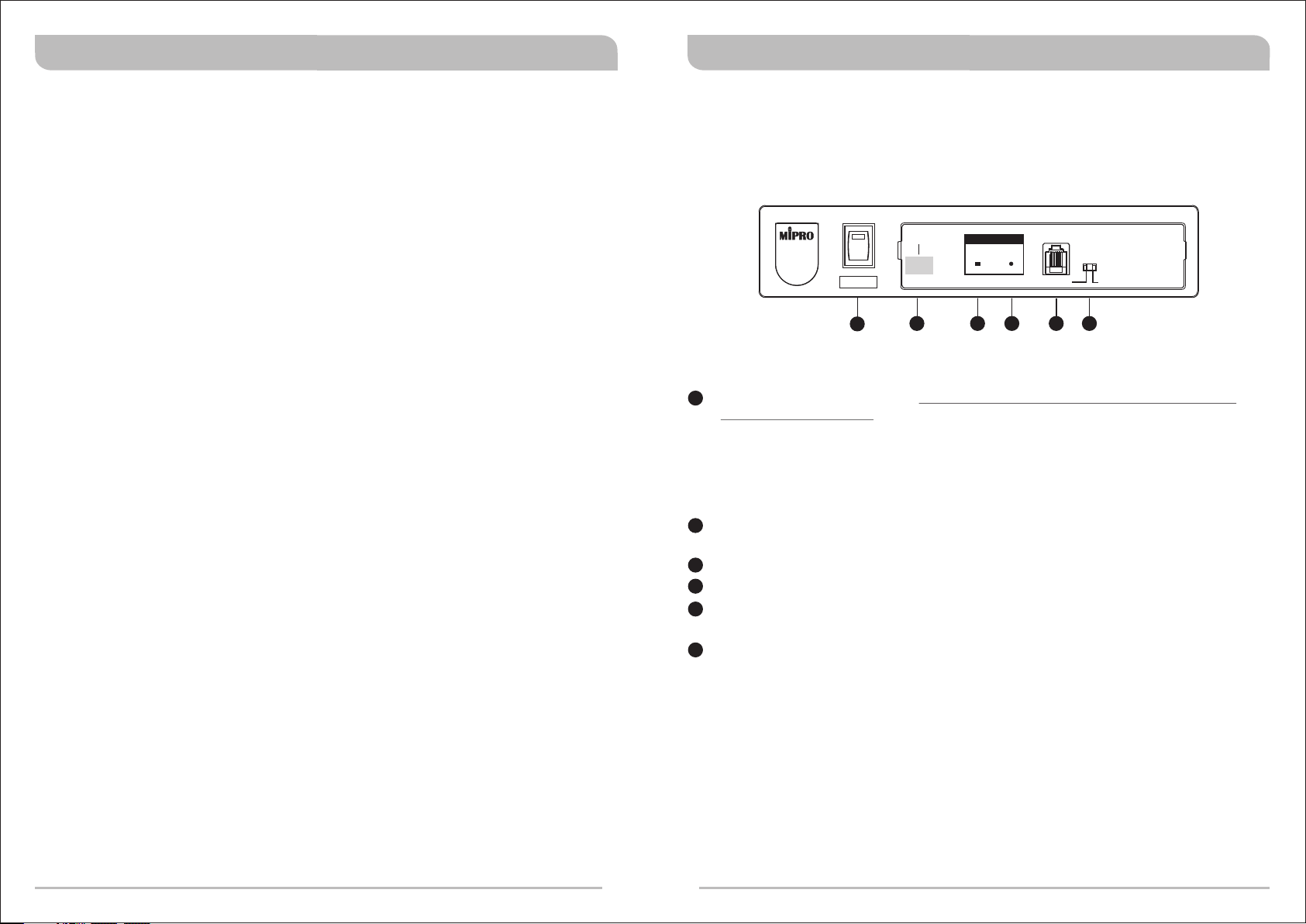
PART NAMES AND FUNCTIONS
Front Panel
ACTPOWER
ACT-101
13 14 15
13
POWER Indicator: Indicates power status. An illuminated indicator denotes receiver
has received IR signal and now turned on.
14
ACT Port: Receive signal to turn on (and off) receiver and sync frequency to
transmitter.
15
EXTEND Socket: Connect enclosed RJ-11 network cable to same EXTEND
location of the main ACT-101 receiver.
NOTE: The purpose of installing an ACT-101 External ACT Port Receiver is to improve
infrared transmitting & reception signal quality for powering on & off the receiver as
its path maybe shielded or blocked. For example, if the main receiver is installed
inside an enclosed rack case, room or similar environments. It can be wall mounted
or stand alone.
EXTEND
(Figure 3)
5
Wa ll Mo unt :
4
5
Page 6

Wireless IR Remote Control Receiver
Wireless IR Remote Control Receiver
RECEIVER INSTALLATION
+
-
CE
1. Antenna Installation: Install two separate antennas on the antenna connectors
12
, from the rear panel. Illustrated in Figure 4.
2. Connecting the Power Supply: Connect the AC/DC power supply to the VDC input
7
jack . Next plug the adapter into an appropriate AC outlet with caution to the
correct voltage and rating. Illustrated in Figure 4.
Note: Red indicator does not illuminate when receiver is plugged-in and pressed.
3. Audio Output Connection:
Unbalanced Output Connection: Using audio cable attached with phone jack
!
type plug, connect one end from the audio output jack of the receiver, and the
other end to the Line input jack of the amplifier or mixer. Illustrated in figure 4.
Unbalanced Level Switch : If unbalanced output socket of receiver connects
!
10
to 〝AUX In〞or ''Electric Guitar'' input socket of mixer and amplifier, the switch
10
level has to be〝+10dB〞. If the switch level is not correct, it will lead to low
sensitivity of microphone or electronic guitar. If unbalanced output socket of
receiver connects to〝 MIC. 〞input socket of mixer and amplifier, the switch level
has to be 〝0dB〞. If not, it will lead to microphone distortion at the volume
slightly turning up and down.
When using the electronic guitar, the switch level
can not be placed at〝0dB〞or〝-6dB〞. Otherwise the volume will be too small.
For some amplifiers which do not have the unified MIC In and are designed for
Karaoke application, you can have the switch in〝6dB〞when no distortion
happening.
Electric Guitar Output: Using audio cable attached with phone jack type plug,
!
connect one end from the audio output jack of the receiver, and the other end
to the “Electric Guitar” input jack of the amplifier or mixer. Switch unbalanced level
10
switch to +10dB. Illustrated in Figure 4.
SQLEVEL
-6dB
+10dB
0dB
(Figure 4)
8
9
10
10
10
9
RACK-MOUNT RECEIVER INSTALLATION
An optional MIPRO FB-11 rack-mount brackets needs to be installed to be fitted into an
EIA standard 19” rack case. Illustrated in Figure 5.
SIGNALACT
IR MODE
EXTEND BUILT-IN
IR MODE
EXTEND BUILT-IN
ACT-101
Wireless Receiver
ACT-101
Wireless Receiver
RF AF
SIGNALACT
RF AF
(Figure 5)
Optional Accessory:
FB-11 Rack-mount Brackets
Rack mount brackets fits a single half-rack receiver
For ideal reception and performance, install
the receiver at least 1 meter (3 feet) above
the ground and away from EMI/RFI noise
sources. In addition, place the transmitter
microphone at least 1 meter (3 feet) away
from the receiving antenna as illustrated in
Figure 7.
m
1
1
m
Ground
m
1
1m
(Figure 7)
W
a
l
l
6
7
Page 7

Wireless IR Remote Control Receiver
RECHARGEABLE MULTI-FUNCTION TRANSMITTER MICROPHONE
OPERATION
!
Make sure the transmitter is OFF position and minimal volume setting on
amplifier/mixer before powering on the receiver.
+
-
CE
!
There is a presence of interference if SIGNAL indicator on the receiver panel is lit,
however, without turning on the transmitter. The built-in Pilotone & NoiseLock squelch
circuitry mutes the audio when experiencing external interferences. At times,
interference can occur with multiple systems being used simultaneously at the same
venue. Adjust the SQ with a screwdriver to mute the interference. However, adjusting
11
the SQ to maximum will reduce the sensitivity level, therefore, reduces the operating
distance.
!
Normal Status: RF indicator will be lit once transmitter is turned on. When feeding
audio into the transmitter, the AF (Audio) indicator will also be lit.
!
Abnormal Status: No RF and/or AF (Audio) indicator is lit when the transmitter is turned
on and feeding audio into the transmitter.
!
Adjusting receiver/amplifier volumes during operation of wireless
microphones:
! Unbalanced Output Level: Volume level switched to ''MIC'' position. Adjusts the
10
volume control on amplifier or mixer to obtain ideal volume level in microphone.
! Mixer/amplifier with over two microphone input sockets: For ideal wireless
microphone sensitivity level, first adjust it in mixer or amplifier using a wired
microphone. Once turned, connect the audio output socket of the receiver. Make sure
switch Unbalanced Level Switch on rear of the receiver to “MIC” level.
10
! Distortion occurs if receiver volume level is set improperly in addition to excessive
microphone volume over amplifier/mixer threshold.
! For proper secured wiring without loose wires follow illustration in Figure 9.
SQLEVEL
-6dB
+10dB
0dB
(Figure 8)
3
PART NAMES AND FUNCTIONS
Front & Rear View
20
16
17
MT-101 ACT
ACT
18
19
16
Microphone: Harden grill protects mic capsule and eliminates pop and wind noises.
17
3.5mm Mini-Jack Input (mono): Accepts external audio sources
(CD/iPod/MP3/tape/computer/DVD) for amplification.
18
ACT Button: To turn on & off ACT-101 receiver. It also syncs the transmitter and
receiver frequency automatically.
19
ACT Power Indicator: Red indicator lits and dims when ACT button is pressed.
This action denotes IR signal is sent.
20
Lanyard Hanger: Secure the transmitter microphone in place with a lanyard in order
to be worn around the neck for hands-free operation.
21
Contact Points: Ensure metal contact points are properly touched inside the battery
charger for re-recharging.
21
18
(Figure 9)
8
9
Page 8

RECHARGEABLE MULTI-FUNCTION TRANSMITTER MICROPHONE
Wireless IR Remote Control Receiver
Side View
TIPS IN OPERATING INFRARED REMOTE CONTROL
Power On & Off Operation:
24
25
ON
OFF
LINEMIC
22
23
22
MIC/LINE Switch: Microphone/Line Switch.
LINE- For electric guitar.
MIC- For general condenser lavalier/headworn microphone or wired microphone.
23
Volume Control: Volume level adjustment.
24
Transmitter Power Indicator: Determines current battery power level.
!Normal Battery: Indicator illuminates and dims when turned on.
!Low Battery: Indicator stays illuminate when turned on. Recharge immediately.
! Drained Battery: Indicator does not illuminate when turned on. Recharge
immediately.
! No Battery or Installed Incorrectly: Indicator does not illuminate when turned on.
! Different Frequency Band: Indicator flashes 4~5 times.
25
Transmitter Power Switch: Power ON to speak or amplification. The RF indicator
on the receiver illuminates to denote it has received signals. Make sure transmitter is
OFF position when not in use or during charging.
10
! The infrared (IR) has an approx. 15-degree trajectory angle for optimal reception.
! The optimal operating range of the infrared remote control is approx. 3-meter/10-feet.
! Press and hold the ACT button towards the ACT Port (2 or 14) of the receiver for at
least 1 second. Ascertain ACT Port Indicator Switch or Power Indicator illuminates
18
1
13
before moving away.
! If ACT Port Indicator Switch or Power Indicator illuminates and dims it denotes IR
1
13
reception was not received successfully. Repeat above steps until indicator illuminates.
11
Page 9

OPERATING INSTRUCTIONS
Wireless IR Remote Control ReceiverWireless IR Remote Control Receiver
To Power ON ACT-101/ACT-101i Receiver:
! Ensure it is plugged into an AC outlet.
! Ensure MT-101ACT transmitter microphone is fully charged.
2
! Aim the bottom of transmitter towards the ACT Port ( or ) .
! Press and hold the ACT button on the transmitter for at least 1 second to power on.
! Still red ACT Port Indicator Switch or Power Indicator denotes the power is on.
! ACT Port Indicator Switch or Power Indicator illuminates and dims denotes the
18
1
1
13
14
13
power is not turned on successfully. Repeat above steps until still red indicator
illuminates.
! Flashing ACT Port Indicator Switch or Power Indicator 4~5 times denotes
1
13
incorrect receiver and transmitter frequency band used.
To Power ON MT-101ACT Transmitter Microphone:
! Once ACT Port Indicator Switch or Power Indicator illuminates red, transmitter
1
microphone is now ready to be turned on.
! Ensure MT-101ACT transmitter microphone is fully-charged.
! Turn on the Transmitter Power Switch .
25
! Speak into the microphone directly for amplification.
13
To Power OFF ACT-101/ACT-101i Receiver:
2
! Aim the bottom of transmitter towards the ACT Port ( or ).
! Press and hold the ACT button on the transmitter for at least 1 second to power off.
! A dim ACT Port Indicator Switch or Power Indicator denotes the power is off.
! DO NOT touch the ACT Port Indicator Switch once is powered off.
18
1
1
14
13
Different Transmitter and Receivers Frequency Bands:
! Each receiver and transmitter has an attached coded frequency label.
! Ensure that both the transmitter and receiver are operating on the same frequency
band in order to power on & off both receiver and transmitter.
! A flashing 4~5 indicator denote incorrect receiver and transmitter frequency band was
used.
! MIPRO's innovative design allows the versatile transmitter to sync any receiver
frequency within the same frequency band.
MT-101ACT Transmitter Microphone Battery Status:
! Normal or Fully Charged Battery:
Red indicator illuminates and dims when Transmitter Power Switch is turned on.
! Low Power Battery:
Red indicator stays illuminate when Transmitter Power Switch is turned on.
! Drained Battery:
Red indicator does not illuminate when Transmitter Power Switch is turned on.
No Battery Inside or Battery Installed Incorrectly:
Red indicator does not illuminate when Transmitter Power Switch is turned on.
25
25
25
25
121314
Page 10

Rechargeable Multi-function Transmitter Rechargeable Multi-function Transmitter
Accepts an External Microphone: Accepts an External Portable Audio Player:
! A headworn or lavaliere microphone with a 3.5mm mini-jack connector can be
connected to the transmitter, worn by a neck lanyard and use as a bodypack
transmitter.
Headworn Microphone
3.5mm(1/8”) Mini-Jack Input
! CD, iPod, MP3, cassette or other audio signals can be connected to the transmitter
via its 3.5mm(1/8”) mini-jack connector to amplified sound. Make sure to switch to
“LINE” when playing
CD PLAYER
3.5mm(1/8”) Mini-Jack Input
Wearing a Neck Lanyard:
!Wearing a lanyard frees your hands during presentation or performance. Adjustable
strap for ideal length and minimizes the distance needed for optimal sound quality
between the microphone and speaker's mouth. Minimize the volume to reduce
chances of feedback.
Lavaliere Microphone
15
Page 11

Rechargeable Multi-function Transmitter Rechargeable Multi-function Transmitter
Charging the Transmitter Microphone:
!Plug into an AC power outlet and the end into the charger itself.
!Insert the transmitter into the battery charger. There are built-in contact points on both
sides of the battery charger. Therefore, either front or back side insertion will charge
the transmitter accordingly.
Battery Charger Indicators:
a
Red Indicator (illuminate): Charging in progress.
b
Green Indicator (illuminate): Fully charged. A fast charge takes approx. 3 hours
then continuous trickle charges.
Battery Charger Troubleshooting:
! Use the attached MIPRO 12V/500mA DC power adapter to avoid insufficient current,
voltage irregularity or damaging the equipment.
! Ensure the transmitter is fully charged before and after use.
! Ensure the transmitter is turned off before placing into the battery charger.
! Check the battery contacts for corrosion or wear. Clean the contacts with dry cloth only.
Water or chemicals can damage the contacts.
! For potential risks and dangers always use the attached MIPRO battery charger only for
charging. Do not place the transmitter in any other unauthorized battery chargers.
! The battery has a limited life. The amount of play time will decrease as the battery
ages or after many recharge cycles. The battery needs to be replaced when play time
becomes too short or when it can no longer be charged.
! Do not place the transmitter into the charger if there is visible battery leakage. Replace
with a new transmitter.
When to Replace the Rechargeable Batteries:
Only a few hours of operation after a fully-charged.
!
No longer holding a charge. (no battery voltage).
!
Short operating distance after a fully-charged.
!
Power indicator does not illuminate when pressed.
!
After 1 or 2 years depending how often it is used. Battery life is determined by
!
temperature, depth and rate of discharge, and the number of charges and discharges
(called cycles).
Excessive wear and tear.
!
Extreme weather conditions.
!
Charging Indicators
How to Change a Battery:
If a new battery replacement is needed, open the battery compartment by removing the
two screws. Insert two rechargeable batteries or disposable alkaline batteries into the
battery compartment with correct polarity placement.
a
b
16
17
 Loading...