

Page 1

UHF Dual Channel Diversity
2 CE 3 6 5 C
Wireless Microphone System
ACT-100
User Guide
All rights reserved. Do not copy or forward without prior approvals MIPRO.
Specifications and design subject to change without notice. MN 014/08
ACT-100A/ACT-100B
Page 2
Dual Channel Wireless ReceiverDual Channel Wireless Receiver
Thank you for selecting MIPRO dual channel wireless microphone system.
Before operating please read this instruction manual carefully and thoroughly
in order to attain the correct operating procedures and achieve the best
results.
This system is a dual channel wireless receiver with two microphones. MIPRO
designs a sophisticated CPU inside the system that can automatically
differentiate the receiving signal strength from the 2 antennas of the receiver.
When an antenna is at its "Receiving Dead Point" and noise interference
starts, the CPU will automatically adjust the system to the antenna that has
stronger signal receiving to avoid signal dropouts and noise interference at
the moment when the wanted signal falls below noise signal. The system has
a "NOISE" indicator to display if the system is under interference and a
newly-added balance adjuster to adjust the volume of both microphones.
This system includes the following accessories:
Audio Output Cable ×2 User Guide ×1
Antenna ×2 (ACT-100A/ACT-100B)
AC/DC Adapter ×1
ACT-100A/ACT-100B Dual-channel Diversity Receiver
Profile
ACT-100 system design has proprietary high performance RF filter and circuitry
improve anti-interference characteristics and increase system compatibility. Ideal for
general stages and professional karaoke applications.
ACT-100A/ACT-100B Key Features
1. EIA-standard 19" 1-rack unit metal chassis with silver gray front panel.
2. Bright RF & AF 5-segment LED meters. Antenna connector on the back panel
connects to a coaxial antenna or extended antenna and provides bias to antenna
booster. Antenna divider can be added or complete MIPRO's antenna systems
ensure best result for both optimal reception and reliable signal quality.
3. Industry's only "NOISE" LED indicator and "sensitivity adjustor". Allows users to
identify the presence of wireless interference and provides adjustability to avoid
problems.
4. Enhanced RF filter and circuitry improve anti-interference characteristics and
increased compatible systems.
5. PLL-synthesized system in UHF band ensures stable performance and low
spurious.
6. Each receiver is preset with 10 channel groups and 102 frequencies total. Easy,
fast and precise channel set-up with preproitary "AutoScan" & "ACT " technology.
7. Innovative CPU controlled dual antenna diversity reception and Pilotone &
Noiselock dual squelch controlled prevents from signal dropout and noise
interferences from computers, karaoke machines and DVD players.
8. 3-step switch for optimum output volume. Output volume is preset to accurately
match the sensitivity of the capsule, adjustment of volume is no longer required
to avoid saturation distortion and ensure user always obtain the optimal output
level and dynamic range.
9. Connects to MIPRO antenna systems.
10. Innovative audio balance tuner replaces traditional design to ensure mixed output
volume of two wireless microphones.
11. High dynamic range and fidelity reproduce the true sound at any sound level for
ACT-100 Dual-channel Diversity Receiver with Built-in Antennas
Profile
New ACT-100 system incorporates a built-in antenna design. All other features and
benefits are the same as ACT-100A system. Ideal for large-scale karaoke and KTV
establishments.
0
1
Page 3
Dual Channel Wireless ReceiverDual Channel Wireless Receiver
1. Part Names And Functions
A. Front Panel
5
6
10
13
SENSITIVITY B
18
12
19
NOISE
B
B
RF AF
CHANNEL
GROUP
1516171411
20
(Figure 1)
9
SENSITIVITY A
NOISE
A
A
BALANCE VOLUME
CHANNEL RF AF
GROUP
3
1
1
Power Switch & Indicator: When switch is turned on, red indicator
2
874
illuminates to denote normal power status.
20
2
ACT Button: Press to synchronize transmitter and receiver frequencies
autotically.
16
3
Group Button: For selection of Group.
17
4
Channel Button: For selection of Channel.
5
18
Group LED Screen: Indicates the selected numeric group.
6
19
Channel LED Screen: Indicates the selected numeric channel.
14
7
RF Signal Indicators: Indicates received RF signals from transmitters.
15
8
Audio Signal Indicators: Indicates the microphone signal.
13
9
Noise Warning Indicator: Red light glows denoting the presence of
interference.
10
12
Sensitivity Adjuster: To adjust receiver sensitivity that ensures no
noise output if receiver is not receiving signals from transmitters.
11
Microphone Balance Volume Adjuster: Allow users to adjust the
mixed volume level of two microphones to a balanced or different level.
Adjuster is factory preset for balanced level.
21
Rackmount Bracket: To install the receiver into an EIA 19-inch
standard rack case.
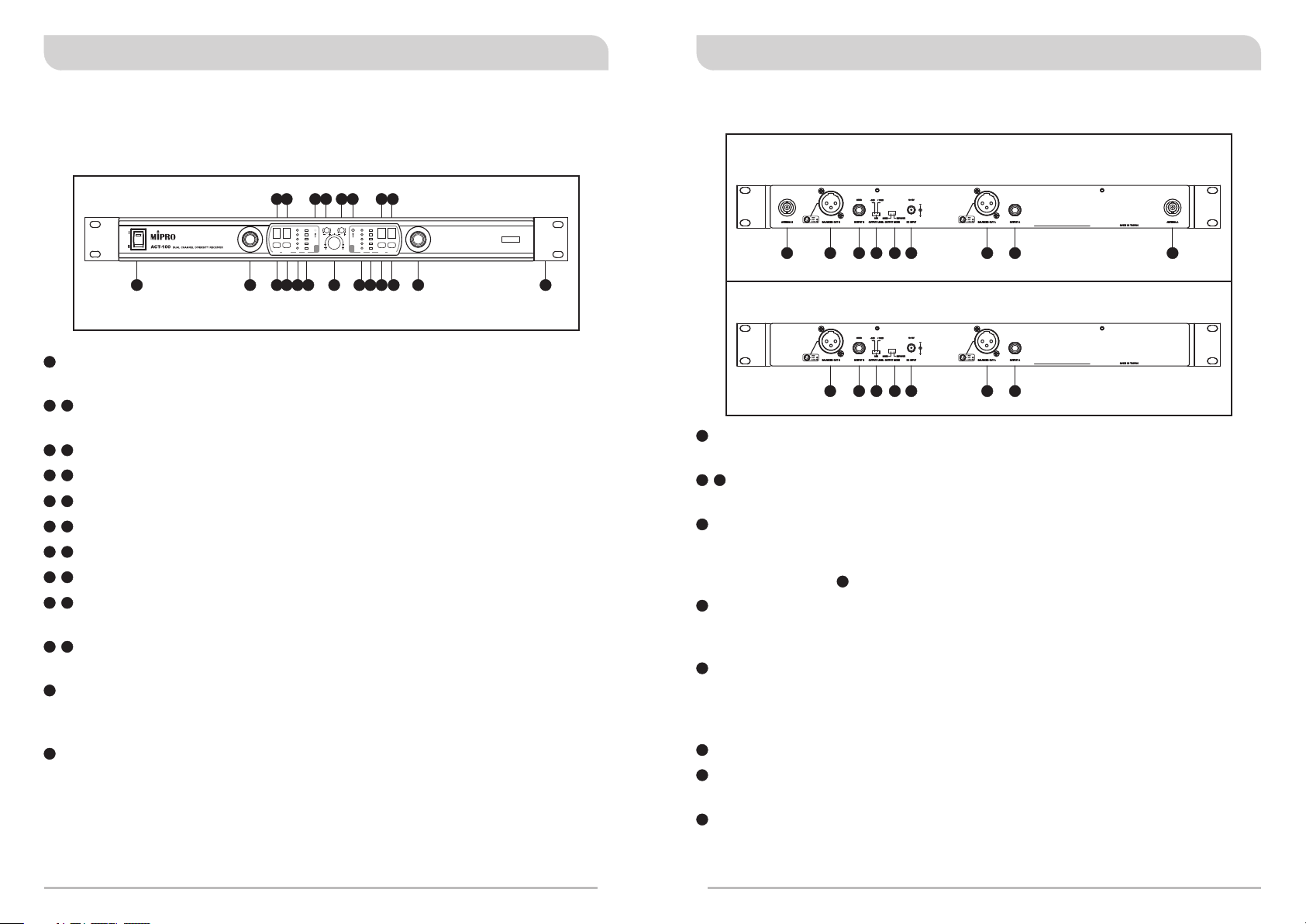
B. Rear Panel
ACT-100A/ACT-100B
23
22
21
252526
24
27
28
29
30
ACT-100
23
22
Antenna B input Connector: To install Antenna B. (ACT-100A/
26
24
27
28
29
(Figure 2)
ACT-100B)
23
28
Balanced Audio Output Jack: With Cannon / XLR type connector
provides balanced audio output signal from this jack to the amplifier.
24
Unbalanced Audio Output Jack B: 1/ 4λ Phone Jack provides
unbalanced audio output signal from Channel B or the mixed output
signals from Channel A & B. (Depend on the position of the unbalanced
mixed switch .)
25
Unbalanced Level Switch: "0dB" selection is for "Microphone-level"
26
output. "+10dB" selection is for "AUX level" output. "-6dB" selection is
for half of cable microphone volume.
26
Unbalanced Mixed Switch: System will have mixed AF output when
switch to "MIXED" position. AF signal from both Channel A & B will be
transmitted from "Output B" only. When switch to "SEPARATE", AF
signal will be transmitted separately from "Output A" and "Output B".
27
DC Input Jack: To connect 12V/1A DC from the AC/DC adapter.
29
Unbalanced Audio Output Jack A: 1/ 4λ Phone Jack provides
unbalanced audio output signal from Channel A.
30
Antenna A Input Connector: To install Antenna A. (ACT-100A/
ACT-100B)
2
3
Page 4

Dual Channel Wireless ReceiverDual Channel Wireless Receiver
2. Installation Of The Receiver
(F ig ur e 3)
1. Install two antennas, perpendicularly and fully extended, to the antenna
30
input connectors & at the rear panel of the receiver, as shown in
Figure 3. (ACT-100A/ACT-100B)
2. Connect the AC/DC adapter cable to DC 12V INPUT JACK , then plug
the adapter unit into an appropriate AC outlet with caution to the correct
voltage under both AC outlet and adapter marked, as shown in Figure 3.
3. Audio Output Connection:
(a) Unbalanced Level Switch Setting Position: When connecting from
receiver's unbalanced output to the "AUX-IN" jack of a mixer or
amplifier or "Electric Guitar", switch the Level Switch to "+10dB"
position. Low sensitivity may occur if switch to the wrong level
position. When connecting from receiver's unbalanced output to the
"MIC-IN" jack of a mixer or amplifier; switch the Level Switch to
"0dB" position. Overload distortion may occur if switch to the wrong
level position. When using electric guitar, don't use "0dB" or "-6dB"
position as it may have generated insufficient level. There are lots of
amplifiers for Karaoke machine in today's market, however, gain of
amplifier's "MIC IN" is not unified. Therefore, if distortion is
encountered, please switch the Level Switch to "-6dB" position.
(b) Connection for Unbalanced Outputs: When the receiver is near the
input/output jacks of mixers/amplifiers, or both systems use phone
jacks, one can connect two separate output cables to unbalanced
output jacks B and A in the receiver. If output mode selector
switches to "MIXED" mode, connect only one unbalanced cable to
unbalanced output jack B as shown in Figure 3.
22
27
25
25
25
25
24
29
24
26
(c) Guitar Output: Using audio output cable attached with "PHONE PLUG"
type, plug one end from the unbalance-mixed output jack of a receiver,
and the other end to the input jack of a guitar amplifier.
Switch the Level Switch to "+10dB" position.
25
(d) Balanced Output: Using audio output cables attached with "XLR" or
"Cannon" type, connect one end from the balanced output jacks B and
28
A of the receiver, and the other end to the "MIC IN" input jack of the
23
mixer or amplifier, as shown in Figure 3. (The characteristic of the 3-pin
connector is as shown in Figure 4)
1: GND
21
3
2: HOT
3: COLD
+
-
(F ig ur e 4)
4. Make sure the system performs correctly, please place the system away
from noise sources. Place the receiver at least 1 meter above the ground
and away from noise sources. Place the microphone at least 1 meter away
from the receiving antenna, as shown in Figure 5.
5. With two rackmount brackets installed, receiver can be mounted into an
EIA standard rackmount case, as shown in Figure 6. As an accessory, you
may purchase from nearest dealer a front antenna kit, which not only
allows easy front antenna installation, but also improves efficiency of
signal reception.
(Figure 5) (Figure 6)
4
5
Page 5

Dual Channel Wireless ReceiverDual Channel Wireless Receiver
3. Operation Instructions
1. Sets the volume of the mixer to its minimum before turning on the
receiver or transmitters. Then, turn on the receiver. The moment when the
receiver is on, indicator on the front panel will flash once to indicate the
system is normal.
10
2. Sensitivity Adjustors allow receiver sensitivity adjustment and
"NOISE" indicators display the optimal adjustment. When neither
transmitters nor "NOISE" indicators turn on, it indicates the system is
under normal standby status. When "NOISE" indicators turn on while
transmitters are off, the receiver is now under interference.
3. If "NOISE" indicators turn on while transmitters are off, it indicates
the receiver is under interference and the receiver will burst loud noises.
Under such circumstances, one can adjust sensitivity adjusters ,
conveniently located on the front panel, counterclockwise until "NOISE"
13
indicators turn off to avoid unwanted loud noise. However, if above
9
attempt should fail, the signal strength of interference is too strong and
other frequencies must be selected to avoid interference. Turning
sensitivity adjusters counterclockwise will reduce both receiver
sensitivity and receiving distance; turning clockwise will increase both
sensitivity and receiving distance.
4. The microphone output level needs to be adjusted at the amplifier or
mixer. No need to adjust at the receiver itself.
12
13
9
13
9
10
12
10
12
4. Switchable Channels Functions
1. Functions:
(a) This system incorporates advanced PLL synthesized oscillator design with
preprogrammed frequencies and displayed on selectable Group and Channel LED
screens.
2. How To Select a Frequency:
17
(a) Manual Channel Set-up: Press and hold CHANNEL button for at least 1 second
6
the CHANNEL LED screen start flashing. If Channel button is not press again
19
within 5 seconds the existing Channel will stay unchanged. If Channel button is
pressed once and hold within 5 seconds it will move to the next channel. If channel
button is pressed and hold continuously it will move to next channel until you
release the channel button.
a) Press and hold " CHANNEL" button for
at least 1 second.
NOISE
B
c) Press " CHANNEL" button and hold
again will move to another numeric
channel.
b) CHANNEL LED screen flashes.
NOISE
B
d) When Channel button is released
the selected channel will be
saved. automatically.
4
NOISE
B
NOISE
B
3. Change channel when:
(a) Existing channel is being interfered or channel is malfunction.
(b) Select channel for multiple non-interference usage.
4. Caution while changing channels:
(a) When multiple channels are utilized do not change channel to avoid exiting channel
interference.
6
7
Page 6

Dual Channel Wireless ReceiverDual Channel Wireless Receiver
5. How To Select a Group:
16
(a) Manual Group Set-up: Press and hold GROUP button for at least 1 second the
5
GROUP LED screen start flashing. If Group button is not press again within 5
18
seconds the existing Group will stay unchanged. If Group button is pressed once
and hold within 5 seconds it will move to the next group. If Group button is
pressed and hold continuously it will move to next group until you release the
Group button.
a) Press and hold "GROUP" button for at
least 1 second.
NOISE
B
GROUP
will move to another numeric channel.
NOISE
B
3
B) LED screen flashes.GROUP
NOISE
B
d) When button is released
Groupc) Press " " button and hold again
the selected group will be saved
automatically.
NOISE
B
5. ACT Button
20
1. Press ACT Button once and release to activate the ACT function.
The Group LED and Channel LED screens will start flashing.
2. Position the red "ACT" marking on the handled or bodypack transmitter
within 30cm towards the ACT Button on the receiver as illustrated in
below diagram (see diagram 8) .
3. If ACT was synced successfully, the Group LED and Channel LED screens
will stop flashing.
2
20
2
< 30cm (12 in.)
OR
6. Change when:
Group
(a) Existing group is being interfered or group is malfunction.
(b) Select group for multiple non-interference usage.
6. Cautions
1. Since the installation of antenna influences the operating efficiency of the
receiver, the most important rule is to minimize the distance between
receiving antenna and microphone for better reception and performance.
2. The external DC power supply should not fall under 12V, otherwise it
would not work properly. If it is over 15V, some components of the
receiver will be damaged.
3. When using multi-channel systems simultaneously, proper channel
frequency selection is very important to avoid mutual interference.
4. Do not use this apparatus near water or any vessel full of liquid (ex. do
not put a vase onto the apparatus).
8
9
Page 7

WARNING
! IMPORTANT SAFETY INSTRUCTIONS !
1. FOR OUTDOOR USE:
To reduce the risk of fire or electric shock, do not expose this apparatus to
rain or moisture.
2. UNDER WET LOCATION:
Apparatus should not be exposed to dripping or splashing and no objects
filled with liquids, such as vases should be placed on the apparatus.
3. SERVICE INSTRUCTIONS:
CAUTION - These servicing instructions are for use by qualified service
personnel only. To reduce the risk of electric shock, do not perform any
servicing other than that contained in the operating instructions unless
you are qualified to do so.
This symbol indicates that dangerous voltage constituting a risk of electric
shock is present within this unit.
This symbol indicates that there are important operating and maintenance
instructions in the literature accompanying this unit.
& IC - ID
THIS DEVICE COMPLIES WITH PART 15 OF THE FCC RULES AND RSS-123 ISSUE1 OF
CANADA. OPERATION IS SUBJECT TO THE FOLLOWING TWO CONDITIONS:
(1) This device may not cause interference.
(2) This device must accept any interference, including interference that may cause
undesired operation of the device. This equipment complies with FCC RF radiation
exposure limits set forth for an uncontrolled environment.
Disposal
200 5-08- 13
Dispose of any unusable devices or batteries responsibly and in accordance
with any applicable regulations.
Disposing of used batteries with domestic waste is to be avoided!
Batteries / NiCad cells often contain heavy metals such as cadmium(Cd),
mercury(Hg) and lead(Pb) that makes them unsuitable for disposal with
domestic waste. You may return spent batteries/ accumulators free of
charge to recycling centres or anywhere else batteries/accumulators are
sold.
By doing so, you contribute to the conservation of our environment!
1. Read these instructions.
2. Keep these instructions.
3. Heed all warnings.
4. Follow all instructions.
5. Do not use this apparatus near water.
6. Clean only with a dry cloth.
7. Do not block any ventilation openings. Install in accordance with the manufacturer's
instructions.
8. Do not install near any heat sources such as radiators, heat registers, stoves, or
other apparatus (including amplifiers) that produce heat.
9. Do not defeat the safety purpose of the polarised or ground plug: A polarised plug
has two blades with one wider than the other. The wide blade is provided for your
safety. When the provided plug does not fit into your outlet, consult an electrician
for replacement of the obsolete outlet.
10. Protect the power cord from being walked on or pinched particularly at plug,
convenience receptacles, and the point where they exit from the apparatus.
11. Only use attachments/accessories specified by the manufacturer.
12. Use only with a cart, stand, tripod, bracket, or table specified by the
manufacturer, or sold with the apparatus. When a cart is used, use
caution when moving the cart/apparatus combination to avoid injury
from tip-over.
13. Unplug this apparatus during lightning storms or when unused for long periods of
time.
14. Refer all servicing to qualified service personnel. Servicing is required
when the apparatus has been damaged in any way, such as power-supply
cord or plug is damaged, liquid has been spilled or objects have fallen into
the apparatus, the apparatus has been exposed to rain or moisture, does not
operate normally, or has been dropped.
15. To reduce the risk of fire or electric shock, do not expose this apparatus to rain or
moisture.
16. Apparatus should not be exposed to dripping or splashing and no objects filled with
liquids, should be placed on the apparatus.
17. Use only with the battery which specified by manufacturer.
18. The power supply cord set is to be the main disconnected device.
 Loading...