

Page 1
WORK STAND W-300 INSTRUCTION MANUAL
Please read this instructions carefully before use.
Thank you for purchasing Minoura “
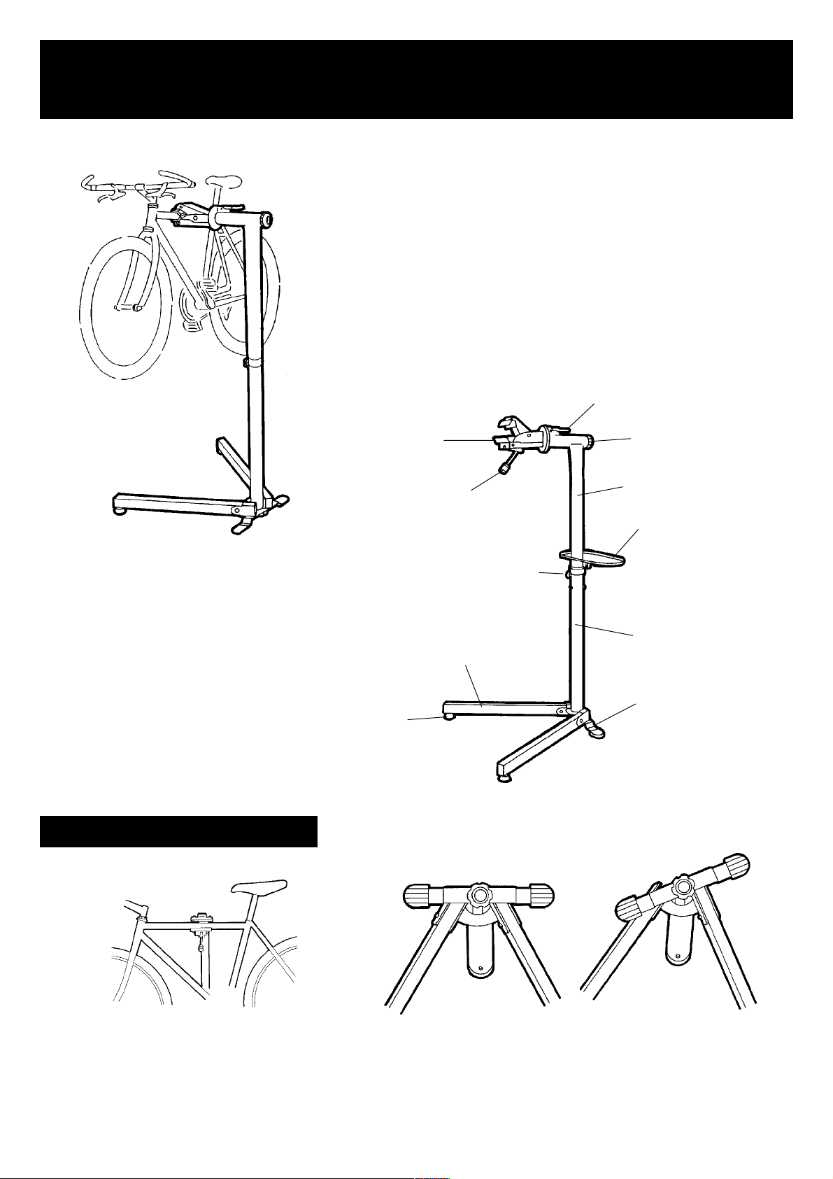
W-300 has foldable leg mechanism so you can save the storage
space when you don’t use this stand.
Also the clamp jaws can rotate fully 360 degrees and fix at any
angle, so you can keep your standing position during your work
even for maintenance on lower part of your bike such as the bottom
bracket or the derailleur.
In addition, this stand can be used as a bike display stand.
Clamp Jaws
Clamp Lever
W-300W-300
W-300” bike repair stand.
W-300W-300
Gear Lever
Clamp Knob
Upper Frame
Tool Tray
(option)
IMPORTANT NOTE
Foot Adjuster
Frame Knob Bolt
Leg
O
Lower Frame
Plate Leg
X
Do NOT use W-300 without
clmaping the frame, otherwise the
bike may fall off.
Set the Plate Leg on proper position otherwise the
stability will be compromised and cause the W-300
to tip during use.
- 1 -
Page 2
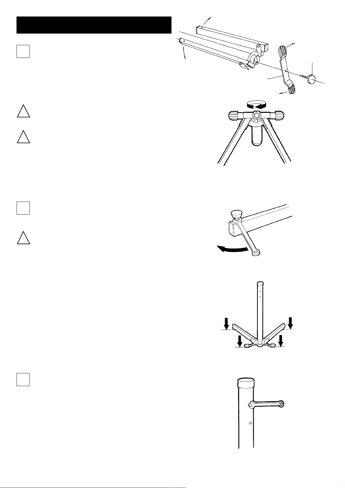
HOW TO SET-UP YOUR W-300
Place the Lower Frame on the level floor and
1
fully open the Leg. Attach the Plate Leg onto
the bottom of the Lower Frame and secure it
with supplied Knob Bolt. (see Fig. A & B)
Be careful not to pinch your finger when you open the leg.
!
Be sure the Plate Leg is installed properly so the Plate Leg
!
doesn’t come over any guide projections. These are
Knob Bolt
Plate Leg
(Fig. A)
located on the bottom of the Lower Frame.
Install the Foot Adjuster on both legs. (see Fig. C)
2
This adjuster is very important for keeping the stand
!
stable for your own safety.
Once you place the completed Lower Frame on the floor,
you should check if ALL edges are touching the floor at
same time (see Fig. D) and adjust the length of each Foot
Adjuster if nessessary. Then fix the position by tightening
the lock nut with a 10mm open wrench.
(Fig. B)
(Fig. C)
Fix the Height Adjusting Screw at your prefered position.
3
There are two holes on the Lower Frame. If you choose the
upper hole, the total stand height will be around 1.3 meter. If
you choose the lower hole, the total height will become 10 cm
lower. (see Fig. E)
- 2 -
(Fig. D)
(Fig. E)
Page 3

Insert the Upper Frame into the Lower Frame (see Fig. F) then
4
fix the position by tightening the supplied small knob bolt and
the spring. (see Fig. G)
Make sure if the direction of the Upper Frame is correct
!
that the “V” shaped cut-off on the bottom of the Upper
Frame must be on the Height Adjusting Screw.
The wrong direction will not align the frame rotation and
will cause stability issues when you clamp your bike on the
W-300.
If you purchased the optional “Tool Tray”, insert it to the Upper
5
Frame before inserting the Upper Frame into the Lower Frame,
and tighten the knob bolt to fix the position and angle. (see Fig.
H)
The Tool Tray is made of steel plate, so you may be in-
!
jured if you scratch the edge of the plate with your finger.
Be careful. (see Fig. I)
If the pedal or something hits the tray during crank rota-
!
tion, move the tray to be behind so its behind the stand
(Fig. F)
(Fig. G)
(Fig. H)
frame.
Insert the Clamp Jaws to the upper horizontal tube of the
6
Upper Frame, insert the washer from the backside then
tighten the knob nut. (see Fig. J)
If you tighten the knob nut so tight, the clamp jaws may
!
not rotate easily. The proper amount of tightening should
be so the clamp jaws can rotate smoothly but without any
!
(Fig. I)
(Fig. J)
looseness.
- 3 -
Page 4

HOW TO USE THE CLAMP
W-300 has unique one lever operation system for both opening/shutting and adjusting the jaws.
Please read the following operation manual carefully and use it effectively and safely.
TO ADJUST THE JAWS
When the clearance between the clamp jaws and the bike is too small,
turn the adjuster knob on the lever anti-clockwise.
When the clearance between the clamp jaws and the bike is too great,
turn the adjuster knob on the lever clockwise. (see Fig. K)
TO OPEN/SHUT THE JAWS
Simply pull down the Clamp Lever, the jaws will open.
Pull up the lever, the jaws will shut. (See Fig. L)
Do NOT adjust the knob AFTER shutting the jaws be-
!
cause this operation will NOT securely hold your bike!
Adjust first, then shut the jaws.
When the turning the adjuster knob anti-clockwise with
!
the lever in the open position, do NOT over-tighten or
force the knob as this will damage the threads on the
lever.
When turning the adjuster knob clockwise with the
lever in the open position, do NOT loosen the knob too
much as this will unthread the lever and could damage
the mechanism.
(Fig. K)
(Fig. L)
TO ROTATE THE JAWS
Push down the Gear Lever to unlock the clamp jaws, then grab and rotate the jaws.
HOW TO REPLACE THE CLAMP RUBBER
1
Remove both E-rings which hold the clamp rubber with a
plier. (see Fig. M)
- 4 -
(Fig. M)
Page 5

2
3
Remove and replace the clamp rubber. (see Fig. N)
(Fig. N)
Push the E-rings onto the rubber projections and finish the
installing new clmap rubber. (see. Fig. O)
(Fig. O)
IF THE CLAMP LEVER HAS COMPLETELY FALLEN OFF...
1
2
3
Once you had removed the thread of the roll nut in the clamp
jaws compeletely by your improper adjustment (Fig. P), you
cannot use it any more.
To fix the problem, remove the clamp bolt completely from
the roll nut (see Fig. Q), then tighten the clamp bolt again and
stop when the first a few threads are seen from the roll nut.
(see Fig. R)
Be sure NOT to over-tighten the bolt until NO threads remain
from the roll nut, otherwise the later steps for adjustment may
be difficult.
Insert the tip of the bolt to the rear roll nut (may be hidden in
the square tubing) and keep this position.
This bolt has a special thread that is opposite to the one on
farthest part. This system makes both roll nuts come together
(Fig. P)
(Fig. Q)
4
when you tighten the bolt.
Stop tightening when the clearance between the roll nuts is
apporoximately one inch (see Fig. S), and check if it becomes
possible to set the bolt down completely in the horrow of the
frame.
- 5 -
(Fig. R)
1 inch
(Fig. S)
Page 6

CONTACT:CONTACT:
CONTACT:
CONTACT:CONTACT:
FOR MORE INFORMATION
MINOURA JAPAN HEAD OFFICEMINOURA JAPAN HEAD OFFICE
MINOURA JAPAN HEAD OFFICE
MINOURA JAPAN HEAD OFFICEMINOURA JAPAN HEAD OFFICE
1197-1 Godo, Anpachi, Gifu 503-2305 JAPAN
Phone (+81) 584-27-3131 / Fax (+81) 584-27-4258
Email : minoura@minoura.jp
http://www.minoura.jp
MINOURA NORTH AMERICAMINOURA NORTH AMERICA
MINOURA NORTH AMERICA
MINOURA NORTH AMERICAMINOURA NORTH AMERICA
(for U.S. and Canada resident only)(for U.S. and Canada resident only)
(for U.S. and Canada resident only)
(for U.S. and Canada resident only)(for U.S. and Canada resident only)
1996 East Avenue, Hayward, CA94541-5454 U.S.A.
Phone 1-510-538-8599 / Fax 1-510-538-5899
Email : MinouraUSA@ATTglobal.net
MADE IN JAPAN
Copyright ©2001 MINOURA CO.,LTD.
- 6 -
 Loading...