

Page 1

INDOOR BICYCLE TRAINER
Minoura Japan Headquarters Minoura North American Center
1197-1 Godo, Anpachi, Gifu 503-2305 Japan (for U.S. residents only)
Phone: +81-584-27-3131 / Fax: +81-584-27-7505 1996 East Avenue, Hayward, CA 94541-5454 U.S.A.
Email: minoura@minoura.jp / URL: www.minoura.jp Phone: 1-510-538-8599 / Fax: 1-510-538-5899
Email: support@minourausa.com
Made in Japan
Page 2

IMPORTANT NOTES
!
• Read all instructions carefully before use.
• Some assembly required. Use correct tools.
• Keep the manual handy at all times.
• Do NOT use trainer for any purpose other than instructed.
• The trainer is manufactured to precise standards. Disassembling or rebuilding by
yourself will void the warranty.
WARNINGS
Use two-wheeled bicycles only. Tandems may be used if balanced correctly.
●
The VFS resistance unit becomes very HOT while using. Do NOT touch the VFS unit during
●
use or for 30 minutes after use.
Minoura strongly suggests you use the supplied Quick Release skewer (for those bicycles
●
that use Q/R systems) and coupling protector cap to insure a secure t of your bicycle to
the trainer frame. If your bicycle has a xed axle nut system you cannot use the supplied
q/r and must make sure that the axle nuts ts securely into the couplings. If they do not t
evenly and securely, our trainer is not compatible with your bicycle and Minoura assumes no
responsibility for such use.
Remove all oils and moisture from the drive roller and the tire before use.
●
Keep both hands on handlebar at all times and maintain a normal riding position.
●
Check the couplings supporting the rear hub for damage and cracks. Accidents may occur
●
from cracked or damaged couplings.
You should not tighten the wheel axle by tightening the left side knob. This is for pre-
●
adjusting the wheel position to the exactly center of the drive roller only. Holding the wheel
securely must be done by the right side hub handle.
When using the trainer, place it on a at and level surface for safe training.
●
Do not over-tighten the hub handles. Overtightening may cause damage to the trainer or
●
your bicycle frame. The clamp handles should be a snug and secure t. Do NOT force!
Before use, make sure all bolts and nuts are securely fastened.
●
Keep away from small children, and keep hands and feet away from spinning rollers and
●
wheels at all times.
Tighten the pivot bolts on the main frame rmly before installing your bike.
●
- 2 -
Page 3
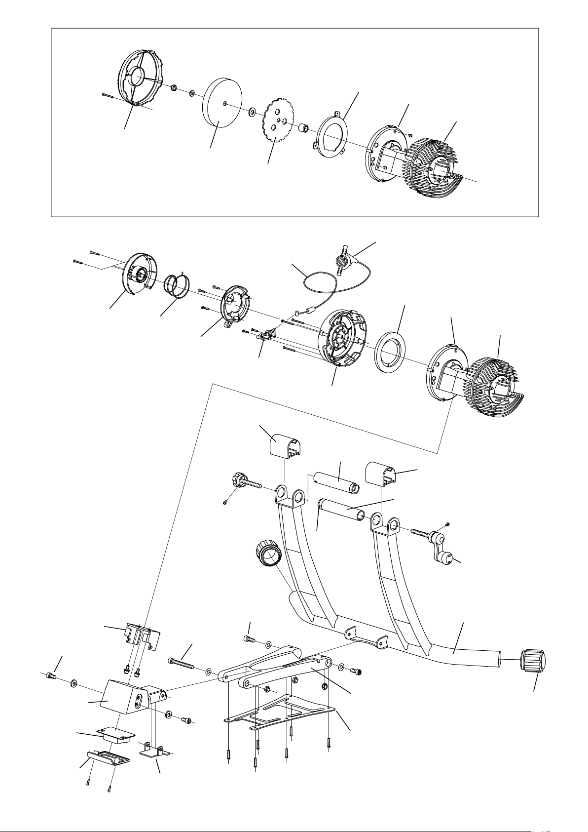
Flywheel Cover
Remote Cover
VFS-G (without remote shifter)
Magnet
Inner Housing
Fluid Unit
Flywheel
Alloy Rotor
Remote Shifter
Remote Cable
Magnet
Inner Housing
Spring
Fluid Unit
Remote Ring
Unit Base
M8x15 Bolt
Remote Bracket
Coupling Cover
Hub Knob
Bolt
M8x70 Bolt
M8x20 Bolt
Outer Housing
Coupling Tube (L)
Coupling Cover
Coupling Tube (R)
Protector Cap
Hub Handle
VFS-G Frame
Mount Base
Pad
Pad Cover
Base Bracket
Sub Frame
Sub Frame Back Plate
VFS-G-R (with remote shifter)
35mm Rubber
Foot Cap
Page 4

ASSEMBLE YOUR VFS-G TRAINER
1
2
Assemble the Sub Frame onto the Main Frame:
The metal Sub Frame Back Plate must be
placed on the bottom of the Sub Frame as
shown in Fig. A.
Insert the M8 Nylon Nut into the hole on the
backside of the Sub Frame. The nylon side
must face inward.
Tighten the M8x20 Bolt and M8 Washer rmly
from both sides.
Install the Unit Base bracket to the
resistance unit:
Make sure the bracket direction is correct
as shown in Fig. B. Wrong direction will not
make the next step successful.
M8x20 Bolt
M8 Washer
M8 Nylon Nut
<Fig. A>
3
Install the assembled resistance unit
onto the Mount Base:
Slide the Unit Base bracket into the
Mount Base.
Choose the best position by referring
Step-5, then x it by tightening M8x15
Bolt and M8 Washer rmly from both
sides.
Unit Base
M6x14 Bolt
<Fig. B>
Mount Base
- 4 -
M8x15 Bolt
M8 Washer
<Fig. C>
Page 5

4
You can adjust the resistance unit position
in 4 patterns to get the best tire contact to
the drive roller for maximum performance.
Wrong positioning may cause damage to
the bearing and the unit housings.
The best hole combination can be seen
on the below matrix and Fig. E.
To change the pivot position between A
and B, remove both the M8x70 Bolt and
the Base Bracket, change the hole then
tighten them again.
If you don't install the Base Bracket, it
may cause unexpected bad stablity of the
resistance unit.
M8 Washer
M8x70 Bolt
Base
Bracket
<Fig. D>
Resistance Unit Position Matrix
Position Best Wheel / Tire Size
A-1 : 650c
A-2 : 26 x 1.40" - 700 x 23c
B-1 : 700 x 25c - 700 x 42c
B-2 : 29"
Depending on the rider's weight, the hole
combination may need to be adjusted.
Sub Frame
B
Mount Base
A
1
2
<Fig. E>
- 5 -
Page 6

PIVOT CAUTION
The pivot between the Main Frame and the
Sub Frame should be tightened rmly for easier
installation of your bike onto VFS-G.
The 6mm Hex Wrench is located in the L-shaped
groove on the Sub Frame.
Use this tool to tighten the pivot bolts.
CAUTION:
To much tightening may break the Sub Frame.
Stop tightening when the Main Frame won't
drop down with its own weight.
6mm Hex Wrench
<Fig. F>
INSTALLING YOUR BIKE ON VFS-G
1
2
Open the couplings by turning both the Hub
Handle and the Hub Knob Bolt in a clockwise
direction.
The left side Hub Knob Bolt is just an initial
adjuster. Once the position is set, you do not
need to adjust the Hub Knob Bolt every time.
For more inforation, please refer the Step-6.
Pull up on the main frame so the unit is as
vertical as possible. This will make the rear
wheel installation easier (see Fig. H & G).
If the pivot bolts are loose, the Main Frame will
drop down with its own weight, so it is crucial
to tighten the pivot bolts rmly.
<Fig. G>
- 6 -
<Fig. H>
Page 7

3
Put the left end of the quick release
skewer (lever side), or axle nut, into
the left side coupling.
Now, adjust the coupling angle so that
the large cutout clamps and lever are
adjusted for easier tting.
Turn the Hub Handle in a counterclockwise direction to close the
coupling.
After engaging the right end of the
quick release skewer (nut side), turn
the Hub Handle until it's locked.
Turning 1 or 2 rotations is crucial for a
secure installation (Fig. I).
<Fig. I>
4
5
Ease the rear wheel down to the drive
roller (see Fig. J).
Now the installation is completed and
you are ready to ride.
<Fig. J>
Now make sure that the Mount
Base is not touching the tire (see
Fig. K).
Lift up the bike again, straighten
the Sub Frame and the Mount
Base then ease the wheel down
again.
If the tire is touching the Sub
Frame, the resistance unit position
is wrong.
Go back to the Step-4 on the
page-5 to adjust to the correct
position.
- 7 -
<Fig. K>
Page 8

6
The tire must be positioned in the center area of the drive
roller (see Fig. L).
If the tire is in contact or touching the other part of the
resistance unit rather than the drive roller (see Fig. M),
adjust the wheel position with the following steps;
1. Loosen the right side Hub Handle.
2. Loosen the left side Hub Adjust Bolt to open the left
side coupling.
3. Clamp the rear wheel axle again.
4. Tighten the Hub Handle rmly.
HOW TO ADJUST THE REMOTE CABLE
If you cannot shift to either L or H, it's the time to adjust the
cable tension.
<Fig. L>
<Fig. M>
1. Set the remote shifter at "H" position.
2. Pull and remove the Cable Cap.
3. Pull out the inside adjusting screw until it touches the
Outer Cable.
4. While holding this position, tighten the nut until it touches
the unit body.
5. Put the Cable Cap again.
STORAGE
Fold the resistance unit at the rear pivot between
the Sub Frame and the Mount Base to minimize
the trainer and to protect the ns on the uid side.
Outer Cable
Cable Cap
<Fig. N>
Inner Cable
- 8 -
<Fig. O>
 Loading...