

Page 1
Wheel Truing Stand
!
!
TRUE-BASE
instructions manual
Wheel truing job
must be done at
your own risk.
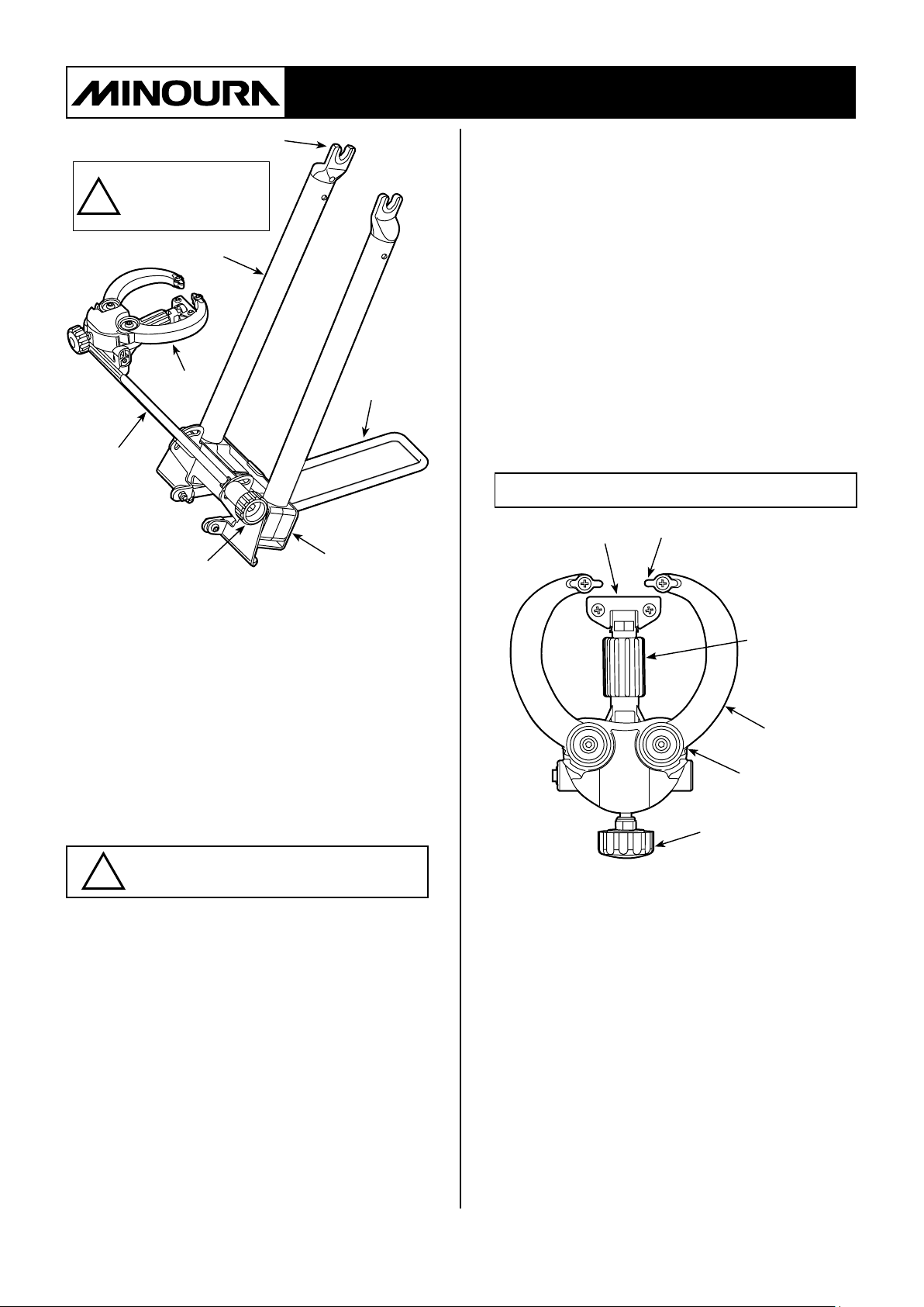
Gauge
Gauge
Stay
Lock Knob
Axle Holder
Pillar
Body
Leg
(Fig. A)
wheel quick release skewer rmly. If the
tightening skewer power is not enough,
either hub side will be lifted up that makes
the wheel becomes angled and you cannot
expect correct result.
• Push down the wheel to set it in the deepest position on the Axle Holder when you
tighten the quick release skewer.
• T-shaped gauge for checking the prior
gauge center position doesn't come with
the kit. Purchase sseparately if necessary.
• Dishing Tool and Nipple Wrench are
necessary for maintaining the wheel but
they are not included in this kit. Purchase
them separately at your local bike shop.
Components
Vertical Gauge
Side Gauge
Thank you for choosing the MINOURA
BASE
True-Base holds a bicycle wheel on top of the pillars
for helping you to maintain the wheel.
The gauges that check vertical and horizontal
movement of the wheel are intuitive and easy to use.
True-Base folds down completely for easy trans-port
and compact storage.
Please read this instructions manual carefully before
use and keep handy at all times for future references.
portable wheel truing stand.
TRUE-
Important Notes
• Do NOT use True-Base for any purpose
other than instructed such as displaying
bike on it.
• Both right and left side pillars move
together for placing the wheel in the same
position whatever the hub width is, but it's
not 100% perfect so we recommend you to
use an optional wheel dishing tool together
for much more precise adjustment. We
don't guarantee any result by using this
stand.
• Axle Holder is a xed type. Depending on
the hub width, you may have to slightly
bend Axle Holder by tightening the
Vertical Gauge
Adjust Knob
Arm
Arm Lock
Side Gauge
Adjust Knob
(Fig. B)
• PILLARS
Both right and left side Pillars are connected in the
body so they will move together at the same time.
You should hold both Pillars with both hands when
opening or closing them.
• AXLE HOLDER
Be sure that Axle Holder is a xed type, not angle
adjustable.
It is crucial to set the wheel into the deepest position
of the Axle Holder by pushing down the wheel when
setting up the wheel on True-Base to get better result.
If one side has been lifted up due to bad installation,
the wheel won't become symmetrical.
- 1 -
Page 2
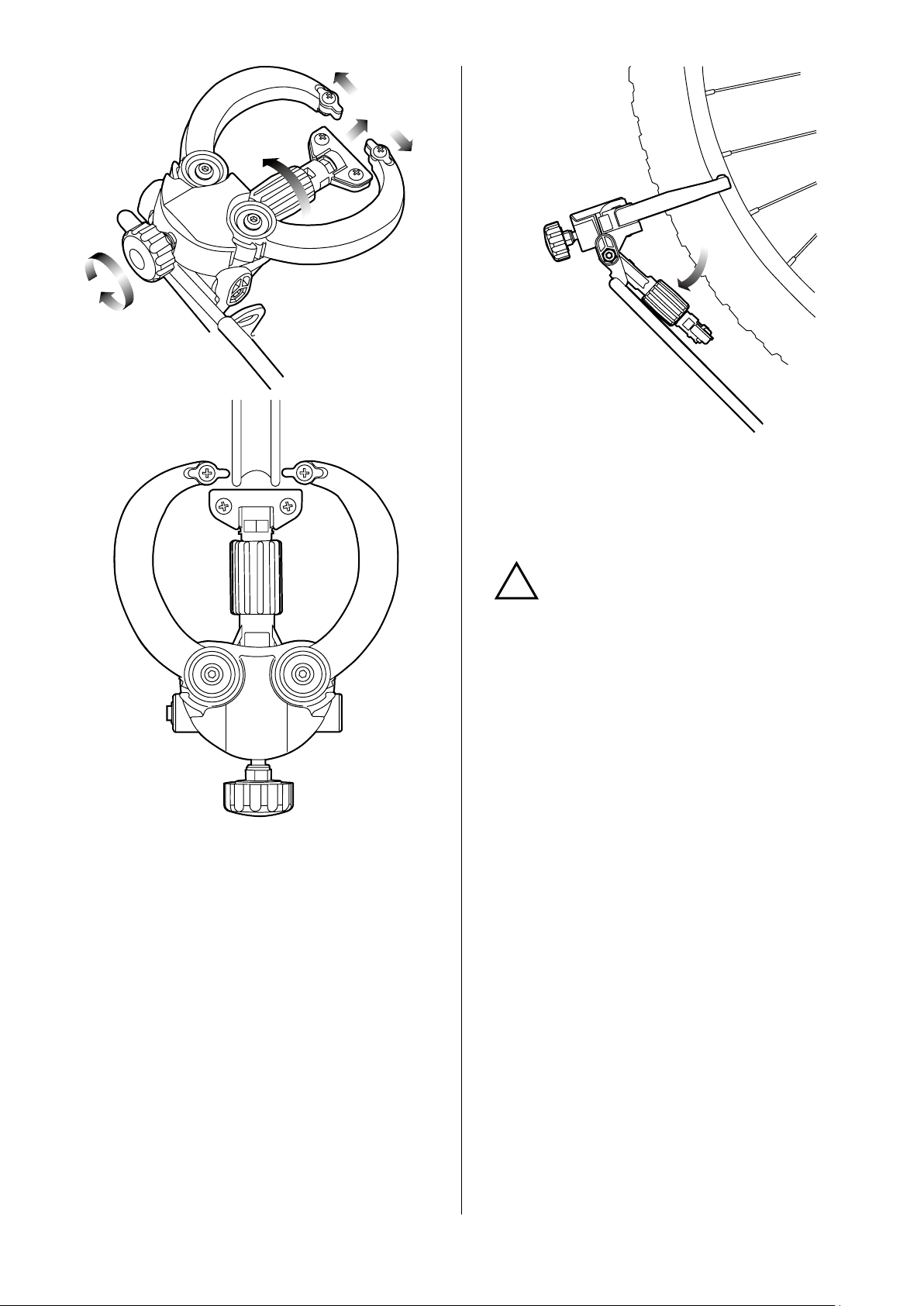
How to Operate
!
Checking Position
Foldable Vertical
Gauge
(Fig. C)
(Fig. E)
The metal tip on the Vertical Gauge can be removed
by loosening two screws if you don't wish to scratch
the soft carbon rim surface.
However, we recommend you keep the metal tip in
contact at all times for getting clearer sound.
(Fig. D)
• VERTICAL GAUGE
Vertical Gauge is for checking the vertical movement
of the wheel. When the rotating wheel comes in
contact with the Vertical Gauge, you will hear a
scratching sound.
To adjust the gauge position, rotate the red barrel
type Vertical Gauge Adjust Knob. (see Fig. C)
Vertical Gauge should be positioned 1 - 2 mm away
from the rim. (see Fig. D)
If the movement is so heavy, you should place the
gauge farther, then set it closer gradually as the
adustment is being done.
If you mount a wheel with tire for just checking the
horizontal movement only, you can fold down the
Vertical Gauge manually. (see Fig. E)
Vertical Gauge may be twisted
slightly.
It must be parallel to the rim, and
both right and left side of the rim
edge must touch Vertical Gauge at
same time.
If it has been twisted and you see
some gap on either side between the
gauge and the rim edge, pinch the
gauge only (not holding the barrel
knob) then turn it.
• SIDE GAUGE
Side Gauge is for checking the horizontal movement
of the wheel. When the rotating wheel comes
in contact with the Side Gauge, you will
scratching sound.
To adjust the opening of Side Gauge, rotate Side
Gauge Adjust Knob, then both Arms will move
together at the same time. (see Fig. C)
Side Gauge should be positioned 1 - 2 mm away
from the rim side wall. (see Fig. D)
If the movement is so heavy, you should place the
gauge farther, then set it closer gradually as the
adustment is being done.
If you already set the best opening size of the Side
Gauge to your rim but the wheel has a tire, you can
open the Arm manually for quicker installation.
- 2 -
hear
a
Page 3
(Fig. F)
!
!
To do so, hold the Arm then open it until it is locked
at the widest position. (see Fig. F)
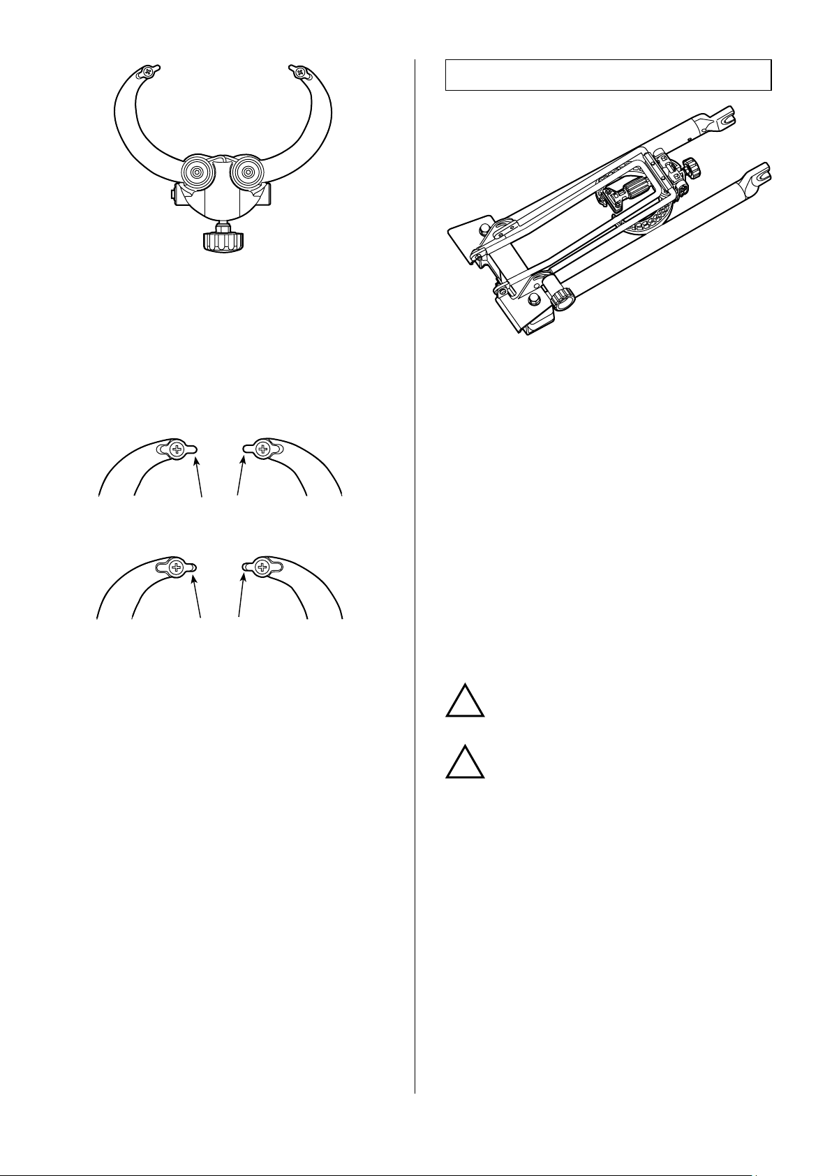
The metal tip of the side gauge can be retracted
by ipping the tip metal piece if you worry about
damage to the side of your rim. (see Fig. G)
However, the contact sound will have to become
smaller so listen more carefully.
How To Fold Down
(Fig. H)
True-Base is completely foldable for easier transportation and compact storage.
To fold down, follow the steps;
Shut the Side Gauge as narrow as possible by
1.
turning the knob.
Loosen the Lock Knob.
2.
Normal Position
(metal tip is projected)
Carbon Position
(metal tip is retracted)
(Fig. G)
Close the Pillars (gently push together).
3.
Fold the gauges downward and push toward the
4.
Pillars.
Flip up the Leg until it touches the Gauge Stay.
5.
Tighten the Lock Knob.
6.
Be careful not to pinch your ngers
between the body, stay and leg.
Do not try to store the gauge
between the pillars.
If strong sideward shock is applied,
the plastic gauges should be broken.
- 3 -
Page 4

About Offset Wheel Setting
!
How To Fix Vertical Movement
At rst, you should understand that you should
x the vertical movement prior to the horizontal
movement, especially on the rear wheel because of
its unique wheel system named
< Offset Wheel >
Tensioning the front wheel is much easier than the
rear because it's symmetric. Rear wheel tensioning
requires Offset Tensioning.
The rear wheel has a different spoke angle pattern
when looking at it from behind. (see Fig. I)
A rear hub is not symmetrical to the wheel. Flanges
can be far from center. Because the rear hub must
have extra space for the set of transmission gears,
you will need to true using Offset Tensioning.
In offset wheel, the torque works mostly only to
the right side (gear side) spokes. Because right side
spokes should be assembled more vertically than left
side.
So you should understand that right side spoke
tension is more important than left side spoke's one
in this offset assembling.
Well adjusted right side spokes can keep your wheel
stable in the future. Left side spoke tension is just a
help.
Understand that the nipple should not be loosened
at any time. Nipples are made from softer alloys or
brass and are prone to stripping easily.
You must use a correct size spoke
wrench which ts the nipples
perfectly, especially when you use
light alloy nipples on your wheel.
If you use wrong size one, the nipple
will become round easily and you
cannot continue your work any more.
"Offset"
.
(Fig. I)
The vertical movement within 3 mm may not
cause any troubles. But if you want to be it as zero
as possible for smoother ride, you should try the
following process again and again.
Be sure, in this case, you should tighten both side of
the nipples equally.
1.
You set the wheel on the True-Base and see the
Vertical Gauge.
Put the tip of the Vretical Gauge close to the surface
of the rim.
2.
Rotate the wheel slowly, and check the vertical
movement. Do not spin fast.
3.
Attach tapes to two spokes; one is in the beginning
and another one is in the ending of vertical
movement.
4.
Make three (3) groups of spokes between your tape
markers as below;
A
B
C
B
A
Group-A
Group-B
Group-C
: 3 or less spokes in the beginning and in
the ending of vertical movement.
: 3 or less spokes between Group-A,
except for the center spoke.
: The center 1 or 2 between the tapes.
5.
If the rim moves to outward, tighten both side
nipples.
If the rim shakes inward, do NOT try to loosen the
- 4 -
(Fig. J)
Page 5

nipples. Tighten both far side nipples.
!
!
!
!
This is because the nipples are made of soft material,
so its thread can be broken easily by loosening.
6.
Tighten the spokes as below;
• Group-B nipples about 1/4 turns
• Group-C nipples about 1/2 turns
Then check the vertical movement again with
rotating the wheel slowly.
If the wheel moves yet, continue the process again.
• Group-A nipples about 1/8 turns
Group-A
Group-B
Group-C
: 3 or less spokes in the beginning and in
the ending of horizontal movement.
: 3 or less spokes between Group-A,
except for the center spoke.
: The center 1 or 2 between the tapes.
5.
If the rim moves to right, tighten the left side nipples.
Do NOT loosen the right side nipples.
This is because the nipples are made of soft material,
so its thread can be broken easily by loosening.
If you hear a strange sound or see
narrow metal "lines" or residue, your
nipple will fail soon.
Do NOT apply any lubricant to quiet
the sound. Put a new nipple on
immediately.
Do NOT tighten the spoke more
than 1/2 turns at one time. Wheel
truing must be done step by step.
Otherwise, you will loose the spoke
tension balance completely.
How To Fix Horizontal Movement
The horizontal movement within 2 mm may not
cause any troubles. But if you want to be it as zero
as possible for smoother ride, you should try the
following process again and again.
1.
You set the wheel on the True-Base and see the Side
Gauges.
Put the tips of them close to the surface of the rim
side wall. Do not make them touch the rim.
2.
Rotate the wheel slowly, and check the horizontal
movement. Do not spin fast.
6.
Tighten the spokes as below;
• Group-B nipples about 1/4 turns
• Group-C nipples about 1/2 turns
Then check the horizontal movement again with
rotating the wheel slowly.
If the wheel moves yet, continue the process again.
• Group-A nipples about 1/8 turns
If you hear a strange sound or see
metal "lines" or residue, your nipple
will fail soon.
Do NOT apply any lubricant to quiet
the sound. Put a new nipple on
immediately.
Do NOT tighten the spoke more
than 1/2 turns at one time. Wheel
truing must be done step by step.
Otherwise, you will loose the spoke
tension balance completely.
There are several ways to true the bike
wheel. Above is just one example and you
don't have to follow our way.
You should ask well-educated mechanics
to get more effective techniques.
3.
Attach tapes to two spokes; one is in the beginning
and one is in the ending of horizontal movement.
4.
Make three (3) groups of spokes between your tape
markers as shown in Fig. J;
- 5 -
Page 6

Limited Warranty Policy
For More Information...
1. Only the original user who purchased this True-Base
in brand-new and unopened condition at an authorized
Minoura dealer, authorized internet retailer or authorized
mail order house (hereafter "Original User") is covered
under the Minoura Warranty Service Program (hereafter
"Warranty Service").
2. Any used or new True-Base, either purchased or given
through a shop, internet auction site or person-to-person
will not be covered under Warranty Service, except under
special circumstances to be determined by Minoura.
3. Original User must keep the original sales reciept and
must present a photocopy of the reciept together with a
claim report to obtain Warranty Service.
4. The warranty period shall start from the date of
purchase. If the reciept is not presented, Minoura reserves
the right to extend or deny Warranty Service.
5. All warranties will be void if the True-Base is damaged
due to user's abuse, disassembly, unauthorized alteration
or midication, or used in any way not intended as
described in the instructions manual.
*Pleasecontacttheshoprst
whereyoupurchasedTrue-Base.
MINOURA Japan Headquarters
(for ALL customers)
1197-1 Godo, Anpachi, Gifu 503-2305 Japan
Phone: +81-584-27-3131
Fax: +81-584-27-7505
Email: minoura@minoura.jp
URL: www.minoura.jp
MINOURA North America
(for U.S. residents only)
1996 East Avenue, Hayward, CA 94541 U.S.A.
Phone: 1-510-538-8599
Fax: 1-510-538-5899
Email: support@minourausa.com
**Forcountriesnotlisted,pleasesee
ourwebsiteatwww.minoura.jptond
theMinouradistributorinyourcountry
andcontactthemforservice.
6. Only issues caused by manufacturer's defects will be
covered to all users at Minoura's expense. The period
expires in a maximum of 7 years after the last production.
7. Minoura may offer paid service for in or out of warranty
products that may include, but is not limited to, repair,
replacement and shipping expenses.
For more detailed information, refer both the attached
"MINOURA LIMITED WARRANTY POLICY" card and our
web site (www.minoura.jp). Web can offer you the latest
and more correct information.
Made in Japan
- 6 -
Page 7

True-Base Resolution Diagram
Screw M4x12
TG-6
TG-7
Cap Bolt M5x25
Cap Bolt M5x10
TG-1
TG-9
TG-8
TG-5
Screw M4x10
TF-5
TG-3
TG-4
TG-2
PARTS NAME
TF-1: Main Body
TF-3: Leg
TF-4: Lock Knob
TF-5: Axle Holder
TG-1: Gauge Body
TG-2: Vertical Gauge
TG-3: Vertical Gauge Plate
TG-4: Arm (Right)
TG-5: Arm (Left)
TG-6: Side Gauge Plate
TG-7: Upper Cover
TG-8: Spring (Right, Silver)
TG-9: Spring (Left, Black)
Tapping Screw
M3.5x12
TF-1
Cap Bolt
M5x15
TF-4
TF-3
Cap Bolt M5x15
 Loading...