

Page 1
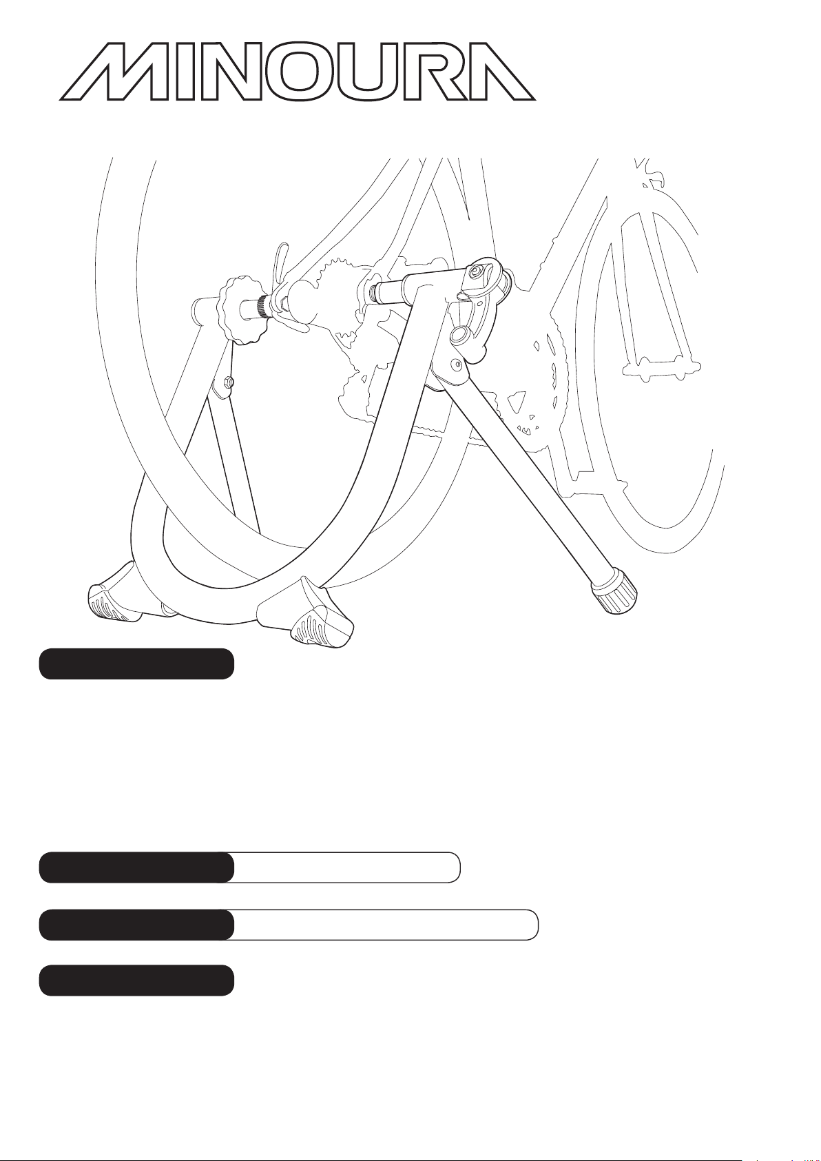
Spinning-Stand
SS-700
Bicycle Maintenance & Display Stand – instructions manual
(Ver.2.0 2015/04)
Important Notes
• Only for normal 2-wheel bicycle with 125 – 140mm rear hub. Any internal transmission rear hub
cannot be used on SS-700.
• Nut type hub bike frame require replacing the left side coupling bolt to the optional longer one.
Old narrow (120mm) bike frame with quick release skewer cannot be mounted even with this
optional bolt. It requires spacing shims separately.
• We strongly suggest you use the supplied skewer to guarantee a proper t with our trainer.
• SS-700 cannot be upgraded to be an indoor bicycle trainer by adding a resistance unit.
Warranty Period
Applicable Tire Size
Contact
1 year
up to
If you have any questions or need help, you should contact the dealer where you purchased or the Minoura
distributor in your country rst. The distributor can be found on our web site.
Only when you cannot get enough service from them, you can contact us;
from purchase
700 x 45c
(ETRTO 47-622)
MINOURA JAPAN
1197-1 Godo, Anpachi, Gifu 503-2305 Japan
Phone: +81-584-27-3131 / Fax: +81-584-27-7505
Email: minoura@minoura.jp
www.minoura.jp
Made in Japan
Page 2
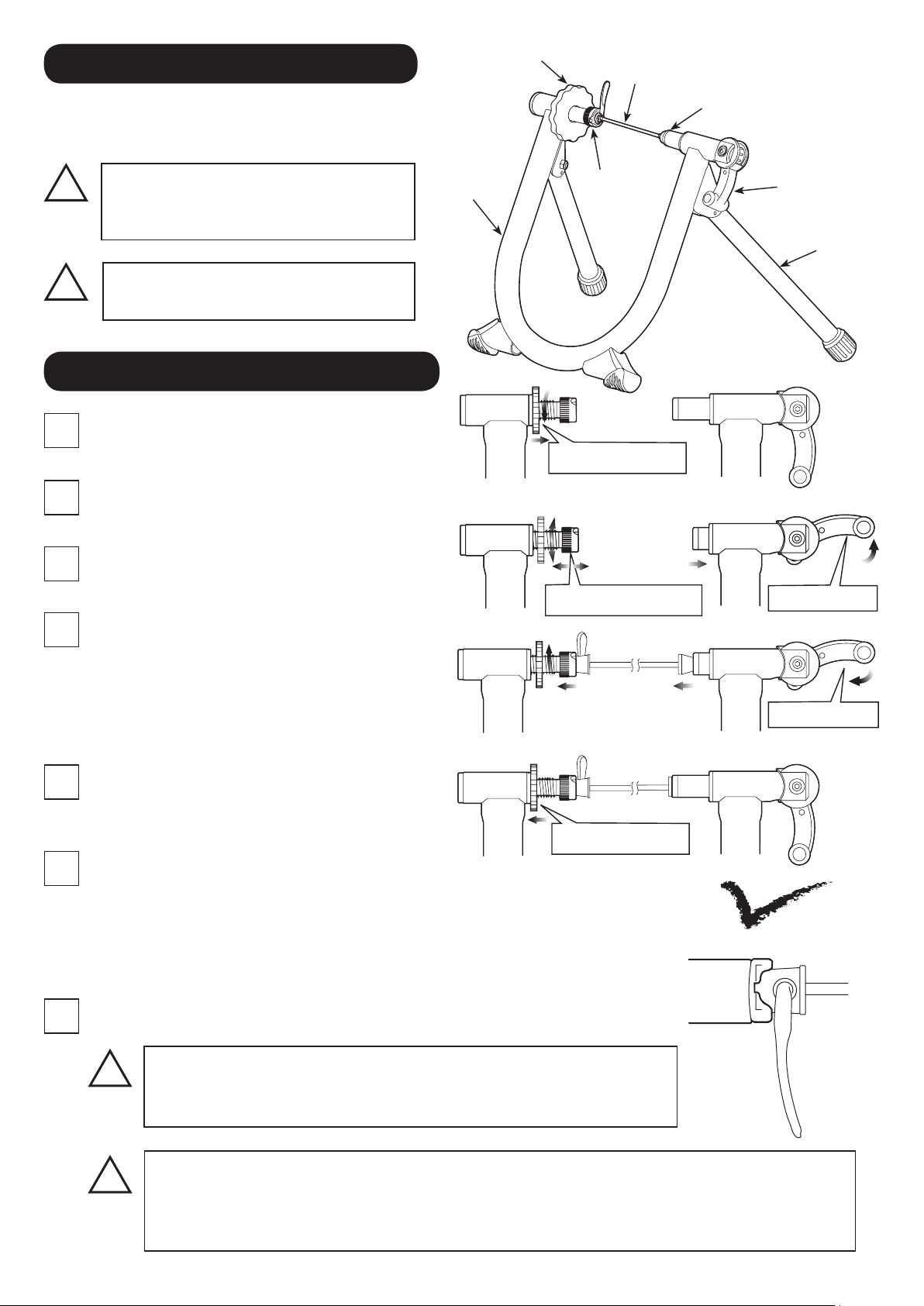
How To Setup Your SS-700
Lock Nut
Quick Release Skewer
Fully open the Legs and place on flat and level floor.
Check if all 4 leg points are touching the floor stably at once.
!
Do not use SS-700 on any sloping
ground. The bike stability will be
Frame
disturbed and may fall down.
!
Be careful not to pinch your nger
when opening and closing the legs.
How To Install Your Bike on SS-700
First, replace your skewer with the supplied one.
1
Loosen the Lock Nut to allow the Left Side
2
Coupling be free. (see Fig. A)
Pull up the Quick Hub Clamp Lever to retract the
3
Right Side Coupling. (see Fig. B)
Insert the left side (quick lever side) skewer into
4
the Left Side Coupling first.
The quick lever shaft must be inserted into the
cut-out on the coupling (see Fig. E) to hold the
bike stable. Turn the coupling to adjust the cutout position.
Left Side
Coupling
Loosen Lock Nut
Turn to adjust position
Right Side Coupling
Quick Hub
Clamp Lever
Leg
(Fig. A)
Pull up lever
(Fig. B)
Push down lever
(Fig. C)
While in this position, bring the bike slowly down
5
to align the right side of the skewer with the
Right Side Coupling. (see Fig. C)
Tighten Lock Nut
Push down the Quick Hub Clamp Lever to hold the
6
rear wheel. (see Fig. C)
If you start feeling resistance when the lever comes at 4 o'clock position, it's correct.
If clamping the hub is too tight or too loose due to wrong position of the Left
Side Coupling, pull up the lever to release the bike, adjust the Left Side Coupling
position, and try clamping the hub again.
Lastly, tighten the Lock Nut to fix the Left Side Coupling position. (see Fig. D)
7
!
Both left and right side couplings are designed to suit the
supplied quick release skewer. The left side coupling must t
perfectly in the skewer head to get correct stability. (Fig. E)
Precisely adjust the left side coupling position to keep the correct thightness of rear
!
hub clamping.
Too tight setting will cause damage to both SS-700 and your bike frame.
Too loose setting may cause the bike to come out of the stand during use.
(Fig. D)
(Fig. E)
 Loading...