

Page 1
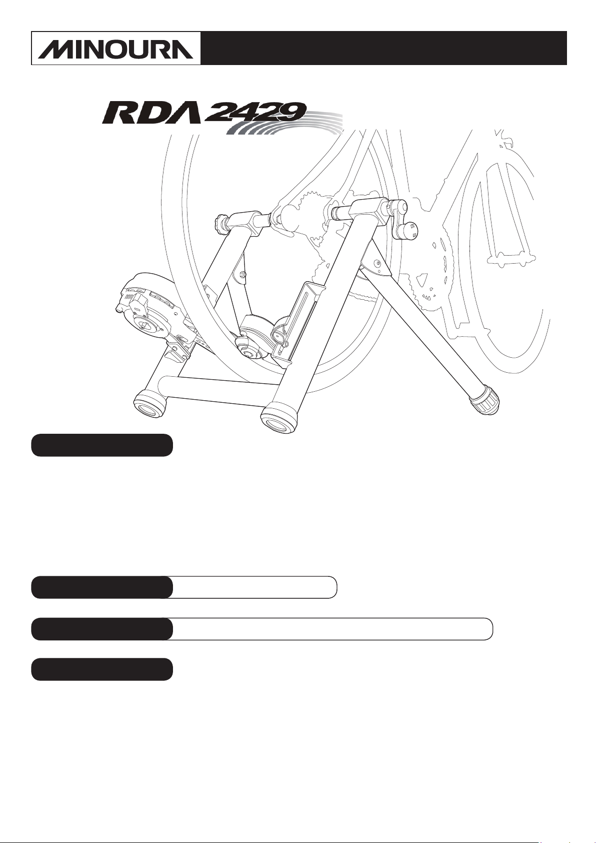
Rim Drive Trainer
RDA2429
Instructions Manual
Read this instructions carefully before use for your safety
(ver.1.1 2014/8)
Important Notes
• Only for normal 2-wheel bicycle with 110 – 170mm rear hub. Any internal transmission rear hub
cannot be used on RDA2429.
• Adjust side pressure on roller wheels to have equal contact against the rim.
• We strongly suggest you use the supplied skewer to guarantee a proper t with our trainer.
• The roller wheels have been specially designed to work with a wide variety of disc rims but we
cannot guarantee 100% compatibility.
Warranty Period 1 year
Applicable Tire Size
Contact
MINOURA Japan Headquarters MINOURA North America
(for ALL customers, including Canada) (for the customers in the U.S.A. ONLY)
1197-1 Godo, Anpachi, Gifu 503-2305 Japan Hayward, California, U.S.A.
Phone: +81-584-27-3131 Phone: 1-510-538-8599
Fax: +81-584-27-7505 Fax: 1-510-538-5899
Email: minoura@minoura.jp Email: support@minourausa.com
Web: www.minoura.jp
24-inch – 29-inch / 650c – 700c (Max = 29 x 2.55")
If you have any questions or need help, you should contact the dealer where you purchased or the Minoura
distributor in your country rst. The distributor can be found on our web site.
Only when you cannot get enough service from them, you can contact us;
from purchase
MADE IN JAPAN
Page 2
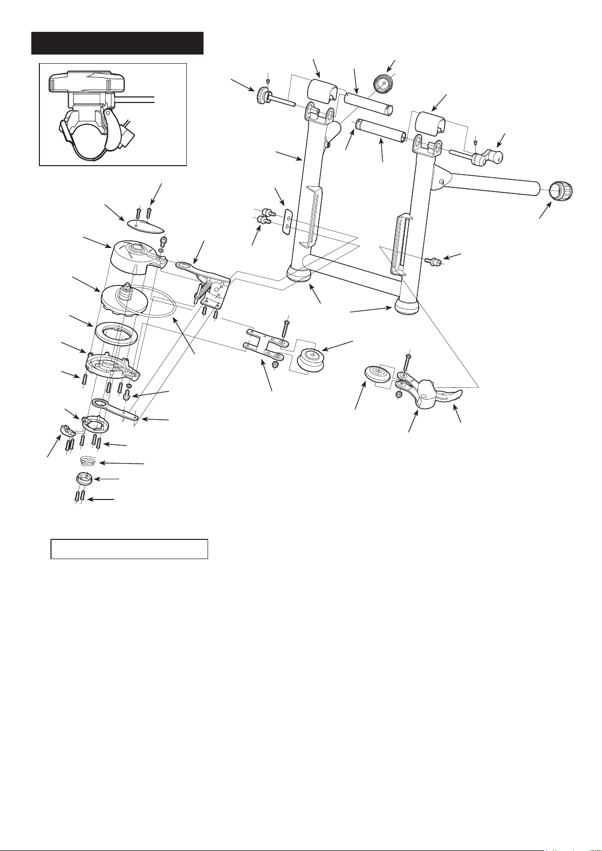
RDA2429 Schematics
F-8
F-4
F-2
M8-4
F-4
ER-7
ER-8
ER-2
L-size
screw
ER-4
ER-3
ER-1
GM-22
(R type)
M-size screw
Bolt with
spring washer
ER-11
S-size screw
ER-10
SR-5
UF-20
SR-13
SR-12
ER-12
F-9
UF-13
ER-27
F-1
ER-26
ER-13
F-7
M8-4
SR-12
ER-14
ER-5
M-size screw
ER-1 : Upper Case
ER-2 : Lower Case
Parts Code / Parts Name
ER-3 : Top Ciover
F-1 : Right Side Coupling ER-4 : Magnet Guide Ring
F-2 : Left Side Coupling ER-5 : Dial Lever
F-4 : Coupling Cover ER-6 : Spring Holder
F-7 : Hub Clamp Handle ER-7 : Flywheel + Alloy Rotor
F-8 : Wheel Position Adjust Knob ER-8 : Magnet
F-9 : Plastic Cap (Grommet) ER-9 : Spring
UF-13 : Rubber Cap (45mm) ER-10 : Main Arm + Pressure Lever
UF-20 : RDA2429 Frame ER-11 : Sub Arm
M8-4 : Rubber Foot Cap (35mm) ER-12 : Pulley Holder
SR-5 : V-Belt (K-16) ER-13 : Assistant Roller Holder
SR-12 : Cap Screw M6x18 ER-14 : Tension Lever
ER-6
ER-9
** Have the parts codes and names ready for your local shop
so they will know exactly which parts you need.
SR-13 : Reinforcement Plate ER-26 : Drive Roller (engraved)
GM-22 : Remote Shifter (White) ER-27 : Assistant Roller (engraved)
Page 3
IMPORTANT NOTES
• Read all instructions carefully before use. And Keep the manual handy at all times.
• Do NOT use trainer for any other purpose than instructed.
• The trainer is manufactured to precise standards. Disassembling without Minoura’s
approval may void your warranty.
• Minoura offers 1-year limited warranty on the Mag unit and 5-year on the frame.
For more detail, refer the enclosed “Minoura Limited Warranty Policy” card.
Use two-wheeled normal bikes only. Tandems and recumbent bikes may be used if balanced
!
correctly. Conrm if your wheel size is in the range between 24-inch and 29-inch / 700c.
You may use the quick release skewer currently on your bike, however we strongly recom-
!
mend replacing your quick release skewer with the supplied one and keep installing the coupling protector cap (F-9) on to the right side coupling of the trainer. Otherwise the stability will
not be guaranteed.
Minoura is not responsible to any problem caused by using your own skewer.
Remove the coupling protector cap when you use a hub nut type wheel.
!
Any hub with internal transmission system or very special type such as Shimano Saint or Hone
cannot be used with this trainer
Depending on the oor or carpet material, the rubber cap may stain. You should not put the
!
trainer directly on the oor, and use a specic oor protection mat or large towel under trainer.
Check the couplings supporting the rear hub for damage and cracks. Accidents may occur
!
from cracked or damaged couplings.
Setup the trainer on at, horizontal and level oor for safe training.
!
Open the legs fully to get maximum stability.
Keep both hands on the handlebar at all times and maintain a normal riding position.
Do not clamp the wheel axle by using the left side knob (F-8). The left side knob is only for
!
pre-adjusting the wheel position for the best pedaling efciency. Use the larger hub handle (F-7)
to tighten the bike to the trainer.
Do not over-tighten the Hub Clamp Handle. Over-tightening may cause damage to both the
!
trainer and bike frame. The clamp handle should be a snug and secure t. Do not force!
Before use, make sure all bolts and nuts are securely fastened.
!
Keep small children and pets away from the trainer, and keep hands and feet away from the
!
spinning rollers and wheels at all times.
Do not allow the rubber rollers to come in contact with the tire. Doing so may cause a cut and
!
puncture in your tire.
Make sure the rubber roller contacts the vertical area of the rim side wall only. Contacting the
slanted area on the tim should cause damage to the rubber roller and the rim surface.
Wipe all oil and moistures out from the rim surface and rollers everytime you use the trainer to
!
keep necessary brake performance of your bike.
Page 4

HOW TO SETUP RDA2429 TRAINER
Fully open the legs and place RDA2429 on a flat and horizontal floor.
1
2
Confirm all 4 leg points are touching the floor at same time to ensure the maximum stability.
NOTE: If legs are uneven when rst opening the trainer, make sure both legs are fully
extended.
Install the Mag Resistance Unit on the left side
slot beside the trainer pillar by the supplied
M6x18 bolts (SR-12) and the small plate (SR-13).
(see Fig. A)
Assistant Roller is set on the right side slot.
NOTE: You must use the Reinforcement Plate
(SR-13) for installing the Mag unit.
This plate will sandwich the slot plate
from outside for mounting the heavy
Mag unit and giving it extra stability.
You don’t need to tighten the bolts
rmly yet. it will be done later.
Required Tool: M5 Hex Wrench
(inuded)
(Fig. A)
3
4
Open both couplings by turning the left side Knob (see Fig. B) and the right side Hub Handle (see
Fig. C) anti-clockwise.
Left Side Adjust Knob
(Fig. B)
NOTE: Do not over-loosen the couplings, otherwise the knob or the hub handle may be-
come unthreaded inside the frame.
NOTE: Please note that the left side knob is not for tightening the wheel hub but for pre-
adjusting the wheel position in order to stabilize the roller pressure to the rim.
Once you have set up the position, you basically no longer re-adjust the knob
while using the same wheel.
Push the right side Tension Lever (ER-14) and the left side Pressure Lever (ER-10) to retract the
rubber rollers to make enough space for installing the tire.
Right Side Hub Clamp Hadle
(Fig. C)
5
NOTE: If it's hard to retract the arm, assist with another hand to pull the roller.
Insert the left side of the skewer (Q/R lever side) into the left
side coupling, and adjust the rotation of the coupling so the
skewer lever sits securely in the large cut-out (see Fig. D).
NOTE: Failure to do so may cause the bike to be loose in the
coupling, possibly causing the bike to fall out of the
stand resulting in damage or injury.
(Fig. D)
Page 5

6
7
Hold the bike firmly by hand and align the skewer nut to the right side coupling.
While keeping this position, turn the Hub Handle clockwise until the coupling comes into contact
with the skewer nut. Keep tightening.
When you feel some resistance to tighten the handle more,
stop tightening after two more revolutions. If you see the pillars start open due to the tightening power, it’s normal.
8
9
Adjust each height of the Mag unit and the Assistant Roller to
fit to your rear wheel perfectly, and then tighten the bolts firmly.
(see Fig. E)
Be sure that the adjustment must be confirmed after tightening the M6x18 bolts.
!
Each rubber roller is made to contact the rim ONLY. Contact with the tire may cause
the tire to burst during use.
The rubber roller is engraved the bottom side to have clearance to fat tire, but make
sure it doesn’t touch the tire at all.
Adjust the wheel position side to side as to both
rubber rollers contact the same point of the rim
equally. (see Fig. F)
There is a double-circle indicator on each pulley
arm. This is just for your reference. Indicator is
guide only for refference.
If the pressure of the drive roller against the rim is
(Fig. E)
too weak, some slippage will occur when pedaling
strongly. To avoid this problem, you should set the
wheel a little leftward.
To change the wheel position, loosen the Hub Handle first, loosen the left side knob, then tighten
the Hub Handle. If not enough, repeat this step.
!
Both rubber rollers should contact the rim at same point equally, but it won’t
cause any serious problem even if the rollers are not aligned.
Indicator
(Fig. F)
THE SKEWER NUT PROTECTOR
We strongly recommend you to replace your rear wheel quick release
skewer to the supplied one at all times if your bike is equiped with a quick
release skewer system. This will guarantee a fit with our couplings.
You can use this supplied skewer for the actual ride on the road.
The right side coupling has a black plastic Skewer Nut Protector “Grommet” (F-9). This is for protecting
the skewer nut from damage during use.
If your rear wheel is not designed for the quick release skewer and uses a hub nut system, you should
remove it by inserting a rod or a pen to the hole (see Fig. G) and then lifting up the Grommet.
Hole
(Fig. G)
Page 6

HOW TO ADJUST THE RESISTANCE LEVEL
The Mag unit provides 7 different levels of resistance power. It can be controlled via a manual lever
(RDA2429-D) or a remote shifter (RDA2429-R). L is the lowest and H is the highest power.
It's also possible to adjust the resistance power by shifting the bike gear. However, if you use the inner
front gear to reduce the power, it will increase the pedaling torque too much then it will make the pedaling
feel very jerky.
So we recommend you to adjust the power on the Mag unit for smoother and more realistic training.
!
!
!
On RDA2429-D, make sure the mag unit has stopped completely.
Do no touch any moving parts such as wheel or belt.
The mag unit always has some resistance, even when setting at the lowest range.
Some slippage is normal when the resistance level on the trainer is set too high.
Use just lighter level in the rst 5 minutes for warming up your muscles and knee
to avoid accident.
You also should cool-down after session with lighter resistance.
RDA2429-D (Non-Remote)
How To Increase Power
To increase the power, slide the lever towarwd H symbol. (see Fig. H)
(Fig. H)
How To Reduce Power
To reduce the power, slide the lever toward L symbol. (see Fig. I)
RDA2429-R (Remote)
How To Increase Power
To increase the power, turn the lever toward H symbol (clockwise). (see Fig. J)
How To Reduce Power
To reduce the power, turn the lever toward L symbol (counter-clockwise).
(see Fig. J)
(Fig. I)
Reduce Power
Indicator
(Fig. J)
Increase Power
Page 7

HOW TO INSTALL REMOTE SHIFTER
RDA2429-R model ONLY
The R model has a convenient remote shifter lever.
You can install it on the handlebar or stem, then you can control
the resistance level without getting off the bike.
Required Tool: M4 Hex Wrench
2
1
Lever
The clamp band is made of thin and flexible soft plastic so it can
be installed on aerodynamic shape handlebar or oval dimension
stem.
!
If your handlebar has quite special shape
or the stem is square dimension type, the
remote shifter cannot be installed.
Hook
Installing Remote Shifter:
1) Pull down the lever and release the clamp band from the hook.
2) Wind the band around handlebar or stem.
3) Put the band tip to the hook.
4) Pull up the lever to tighten the band.
The flexible plastic band is pre-adjusted to fit normal 22mm diameter
handlebar.
If you need to mount onto an oversized or specially shaped handlebar
or stem, adjust the band by turning the plastic screw on the band with
an M4 hex wrench (see Fig. M).
(Fig. K)
Clamp Band
(Fig. L)
(Please be advised that this hex wrench doesn’t come with the kit.
Prepare by yourself.)
(Fig. M)
!
Both clamp band and screw are made of plastic so they are fragile.
You should take off the hook to prevent from the breakage of those plastic parts.
HOW TO ADJUST CABLE TENSION
If you get unable to set at L or H even though you operate the remote shifter lever, it's the time to adjust
the cable tension. Follow the steps below;
1) Straighten the cable as much as possible, and set the shifter at "H" position.
2) Pull out the small black plastic cap on the cable, then an adjusting screw gets exposed.
3) Put the black outer cable to the remote shifter, and put the adjusting screw to the outer cable.
4) While keeping this position, screw the lock nut toward the Mag unit until it touches the plastic parts.
5) Put the black plastic cap on.
Page 8

ABOUT SLIPPAGE PROBLEM
Minoura's Rim Drive System works off the wall of the rim, not the tire. This system allows use on a wide
variety of rims including disc brake rims. Slipping will happen when pedaling strongly or the resistance
on the mag unit is set high. This slippage is normal and to be expected.
If you experience slippage all the time you use the trainer, check the belt tension first by pushing down
the belt with your finger. The K-16 V-belt will be worn down after long term of use but most reason for
the slippage problem is caused by improper (too much or too less) tension adjustment.
To adjust the belt tension, loosen both upper and lower bolts which hold the pulley arm by an M5 hex
wrench, then pull the arm outward by your hand and tighten the bolts firmly again.
If the V-belt is completely worn down or damaged, replace it.
This work requieres high skill for disassembling and assembling the Mag unit. If you don’t have confidence, please ask to the Minoura dealer where you purchased the trainer.
 Loading...