

Page 1

1
Page 2

32
Thank you for purchasing a Minolta camera.
A valuable tool for photographers, the Maxxum/Dynax 7 has been
designed with precision in mind to help you capture your photographic vision. As you use the Maxxum/Dynax 7, you will find that
its performance and reliability compliment your own photographic
expertise and raise your skills to a higher level.
The Maxxum/Dynax 7 features a newly developed 9-point AF system with center dual cross-hair sensors to give great flexibility when
composing photographs, and the ability to switch between AF and
MF, using the AF/MF control button, without changing holding positions.
This is the first camera ever to incorporate a Navigation display
which gives easy to understand information on camera operation
and Custom functions, available in 5 languages. Combined with the
conventional lever and dial controls, the Navigation display provides
flexible and clear operation.
This manual has been designed to help you understand the operation of your camera and its functions. Please familiarize yourself
with the names of the controls and their locations on the camera,
then read the Basic Operation section. Once you’ve mastered basic
operation, move on to the Detailed Operation section to expand
your expertise.
This camera is designed to work specifically with lenses and accessories manufactured and distributed by Minolta. Using incompatible
accessories with this camera may result in unsatisfactory performance or damage the camera and accessories.
FOR PROPER AND SAFE USE
Read and understand all warnings and cautions before using this product.
WARNING
Batteries may become hot or explode due to improper use.
• Use only the batteries specified in this instruction manual.
• Do not install the batteries with the polarity (+/–) reversed.
• Do not subject batteries to fire or high temperatures.
• Do not attempt to recharge, short, or disassemble.
• Do not mix batteries of different types, brands, or ages.
• Tape over lithium battery contacts to avoid short-circuit when disposing of batteries, and follow local regulations for battery disposal.
Keep batteries and other things that could be swallowed away from
young children. Contact a doctor immediately if an object is swallowed.
Immediately remove the batteries and discontinue use if…
• the camera is dropped or subjected to an impact in which the interior
is exposed.
• the camera emits a strange smell, heat, or smoke.
Do not disassemble. Electric shock may occur if a high voltage circuit
inside the camera is touched. Take your camera to a Minolta Service
Facility when repairs are required.
Do not look directly at the sun through the viewfinder.
CAUTION
Do not allow a camera lens to point directly at the sun. Fire may occur if
sunlight comes to focus on a flammable surface. Replace the lens cap
when the product is not being used.
Page 3

54
TABLE OF CONTENTS
Table of Contents..............................................................................4
Name of Parts...................................................................................8
Quick Operation..............................................................................14
BASIC OPERATION
Batteries..........................................................................................17
Loading Film....................................................................................20
Handling the Camera......................................................................23
Taking Pictures in Full-Auto ............................................................24
Focusing..........................................................................................28
Using the Built-in Flash...................................................................31
Rewinding the Film..........................................................................33
DETAILED OPERATION
Navigation Display ..........................................................................36
Display Selection .................................................................37
When Upper Part Turns Black .............................................43
Display Brightness/Contrast ................................................44
Focusing
Focus Mode.........................................................................46
AF/MF Control Button..........................................................50
Focus Area...........................................................................53
AF Illuminator.......................................................................59
Exposure
P Mode.................................................................................61
A Mode.................................................................................63
S Mode ................................................................................66
M Mode................................................................................69
Metering
Selectable Metering.............................................................74
Exposure Compensation .....................................................77
Automatic Exposure Lock (AEL)..........................................81
Setting the ISO Manually.....................................................86
Drive
Continuous ..........................................................................88
Self-Timer.............................................................................90
Exposure Bracketing............................................................92
Multiple Exposure ...............................................................96
Flash
Flash Mode Switch ..............................................................99
Red-eye Reduction............................................................100
Rear flash Sync .................................................................101
Slow-shutter Sync..............................................................102
Flash Compensation..........................................................103
Flash Bracketing................................................................104
Accessory Flash ................................................................107
Flash Metering...................................................................108
High Speed Sync...............................................................110
Wireless/Remote Off-camera Flash...................................112
PC Terminal........................................................................118
Additional Features
Date/Time Imprinting..........................................................120
Eye-Start............................................................................125
Time Exposures (Bulb)......................................................126
Depth-of Field Preview ......................................................128
Diopter Adjustment ............................................................130
Setting/Cancelling the Audio..............................................131
Page 4

76
TABLE OF CONTENTS
Memory
Storing memory .................................................................135
Recalling settings in memory.............................................137
Data memory
Storing the data .................................................................141
Film area and data number ...............................................143
Data recall..........................................................................146
Deleting stored data...........................................................151
Custom Functions
1 AF priority/Shutter-release priority
2 Film rewind start
3 Film tip
4 DX memory
5 Release lock (film)
6 Lens focus-hold button
7 Eyepiece sensor activation
8 Frame counter
9 AF/MF control button
10 AE-lock button
11 Exposure bracketing/Flash bracketing sequence
12 Film rewind speed
13 Meter display duration
14 AF area display
15 Front and rear control dial Lock
16 Release lock (lens)
17 AF drive speed
18 Exposure compensation control with rear control dial
in P, A, and S mode
19 Control dial - exchanged control
20 Flash-metering
21 AF illuminator
22 Tasking on the focus-mode switch - AF-Aposition
23 AF using shutter-release button
24 Full-auto mode of the exposure-mode dial
25 Tasking on exposure mode dial - position “3”
26 Flash burst with exposure compensation
27 Detailed display
28 Operation display
29 Large icon display
30 Meter index display
31 Exposure-history display
32 Vertical display
33 Imprint intensity
34 Camera’s ID number
35 Language on navigation display
APPENDIX
Accessory information .......................................................189
Trouble shooting................................................................192
Care and Storage ..............................................................196
Specifications .....................................................................198
Index..................................................................................202
Page 5

98
Camera Body
AF illuminator (59)/Selftimer lamp (90)
Battery-chamber release (17)
Vertical-control-grip
contacts (189)*
Battery-chamber
door
Tripod socket
* Do not touch
NAMES OF PARTS
Accessory shoe (107)
Eyepiece cup (15)
Drive-mode lever (87)
Exposure-mode dial lockrelease button (24)
Viewfinder* (12)
Eyepiece sensor* (125)
AE-lock button (81)
Top data panel (10)
Navigation display (36)
Metering-mode switch (75)
Displayselection
button (37)
Navigation-display
illuminator (44)
Diopter-adjustment dial (130)
Control-panel door (120)Manual-rewind button (34)
Eye-start switch (125)
AF/MF control button (50)
Main switch (13)
Strap eyelet (16)
Film window
(20)
Focus-area
selector (55)
Flash-mode
switch (99)
Exposure-mode dial (60)
Rear control
dial
Spot-AF button (52)
Wide/Local
focus-area
switch (54)
Focus-mode switch (46)
Lens release (19)
Strap eyelet (16)
Built-in
flash* (31)
PC terminal
(118)
Lens mount
Back-cover release
(20)
Shutter-release
button
Exposure-compensation dial
lock-release button (77)
Grip sensor
(125)
Exposure-compensation
dial (77)
Flash-compensation dial (103)
Front control
dial
Lens contacts*
Mirror*
Remote-control
terminal (191)
Depth-of-field preview button (128)
For information on specific parts, refer to the page numbers shown in
parenthesis.
Page 6

1110
NAMES OF PARTS
Control Panel
Top Data Panel
Cartridge mark
Film-transport signals
Frame counter/
Aperture display
Adjust button
Enter button (135)
Custom button (154)
Date button (120)
ISO button (86)
Data-memory button
(141)
Shutter-speed display
Navigation Display
Release-priority indicator (158)
Exposure-mode indicator (60)
Flash-mode indicators
(99)
AF-mode indicator (46)
Metering-mode indicator
(74)
Focus-area indicator (46)
Data-memory-on indicator (141)
Battery-condition indicator (18)
Imprint indicator (120)
Display-selection indicator (147) Focus-area-selector indicator (142)
Shutter-speed display
Aperture display
Exposure-compensation display
(77)
Drive-mode indicators (87)
Flash-compensation display
(103)
Frame counter
Film-transport signals
Cartridge mark
Audio-on indicator (131)
Page 7
1312
NAMES OF PARTS
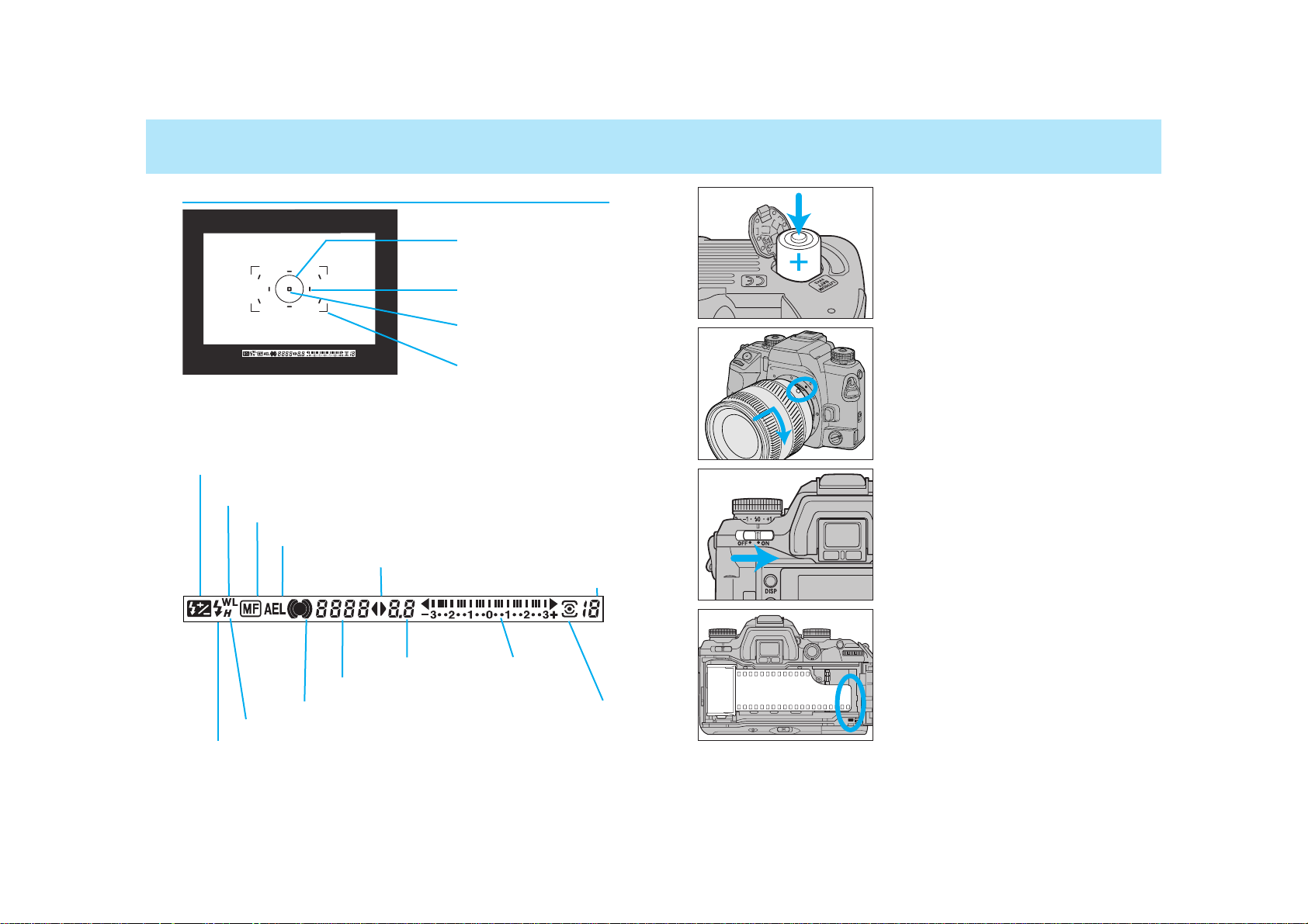
Viewfinder
AEL indicator (81, 102)
Focus signals (28)
Flash-compensation indicator (103)
Spot-metering area (75)
Spot-focus area (55, 56)
Flash indicator (31)
High-speed-sync indicator(110)
Wireless/Remote flash indicator (114)
Shutter-speed display
Exposure-mode indicator
Aperture display
Meter index
Metering-mode indicator (75)
Frames-remaining counter (26)
Manual-focus indicator (48)
Wide focus frame
Local focus area (56)
QUICK OPERATION
1. Insert the batteries.
• The camera uses two CR123A batteries.
2. Attach a lens.
• Align the red marks, then turn it gently clockwise until it clicks.
3. Turn the camera on.
• Turn the main switch to ON.
4. Load the film
• Align the film-tip with the red mark,
then close the back cover.
Page 8
1514
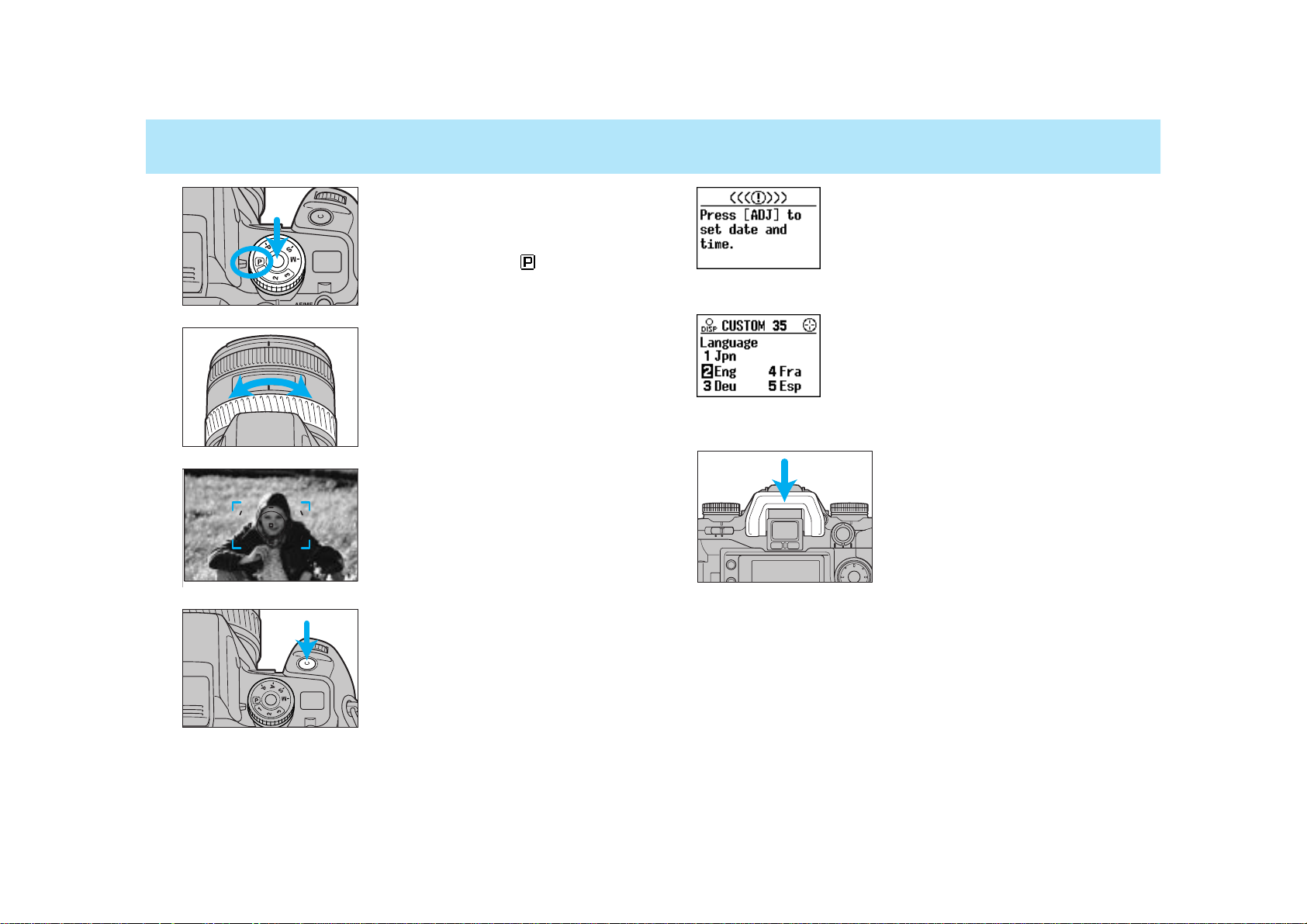
QUICK OPERATION
5. Set the camera for automatic
operation.
• While pressing the exposure-mode
dial lock-release button, set the
exposure-mode dial to .
6. If using a zoom lens, rotate the
zooming ring to frame your
subject as desired.
7. Center your subject in the
focus frame, then press the
shutter-release button partway
down.
• Focus is set automatically.
8. Take the picture.
• Gently press the shutter release button all the way down.
If the camera is turned on and the date and
time have not been set, this message
appears. See page 121 for instructions for setting the date and time.
The navigation display panel can provide information in any one of five languages
(Japanese, English, German, French, or
Spanish). To select the language you wish to
use, see Custom 35 (p. 187).
Attach the eyepiece cup for comfortable viewing.
Page 9

1716
Attach the strap as shown.
Your camera uses two 3V CR123A lithium batteries to supply power
for all camera operations.
1. Turn the main switch off. Then
slide the battery chamber
release as shown, and open
the door.
2. Insert the batteries as indicated by the + and - marks.
3. Close the battery-chamber
door.
Installing the Batteries
If the camera’s batteries are removed for a
long period of time, the date and time settings
will be lost. When this happens, this message
appears, and the date/time information will not
be imprinted. See page 121 for instructions for
setting the date and time.
BATTERIES
BASIC OPERATION
BASIC
OPERATION
• If you have Remote Cord RC-1000S or RC 1000L, you can use the
cord holder on the strap. Attach the strap so that the holder comes to
the side of the remote-control terminal (p. 191).
Page 10
1918
BATTERIES
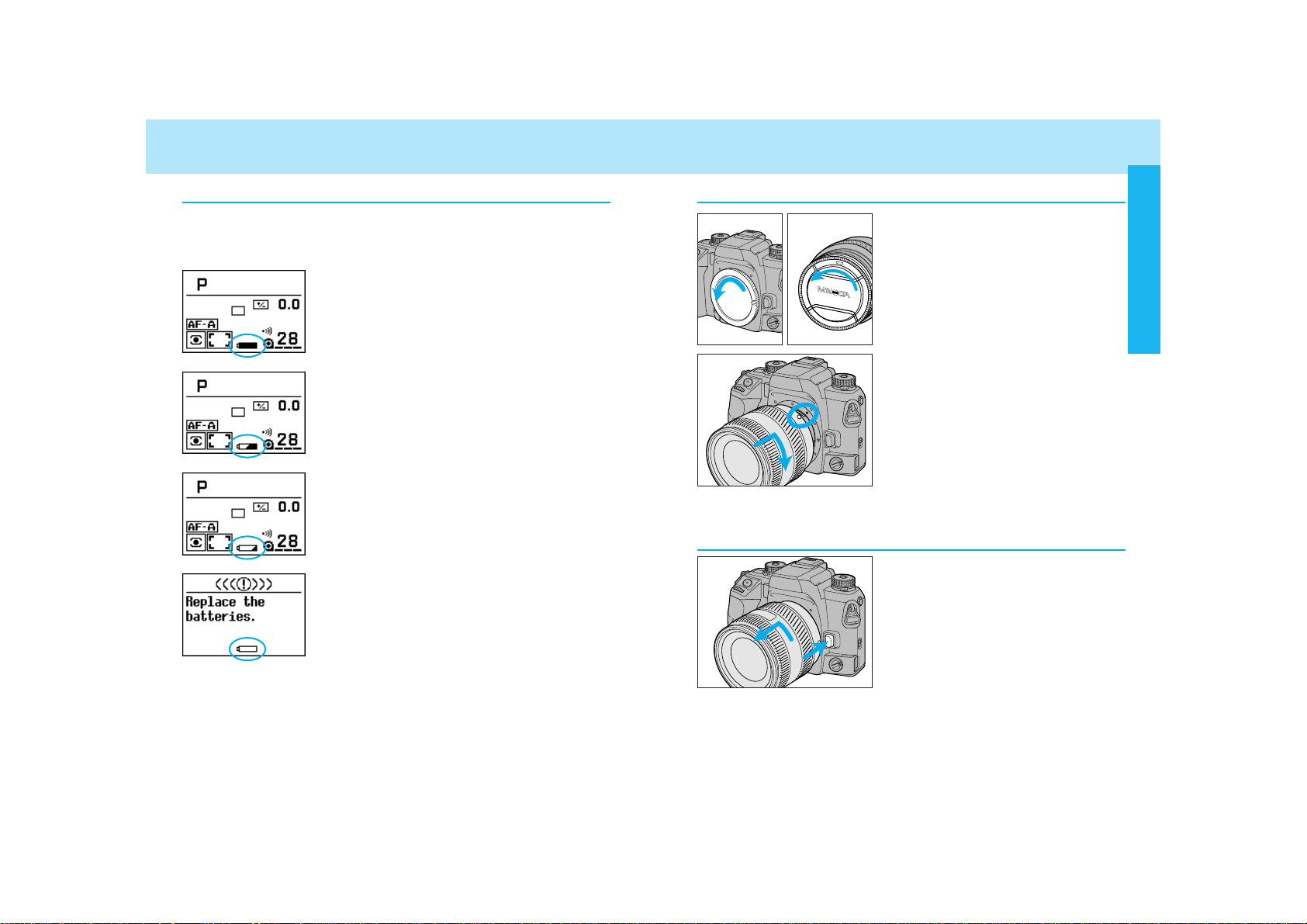
Battery Condition Indicators
The battery condition indicator displays the power status of the batteries when the main switch is set to ON.
Full-battery indicator
Power is sufficient for all camera operations.
Half-battery indicator
Power is low, but all functions are operational.
Keep a fresh battery handy.
Low-battery indicator
Power is extremely low. The batteries will
need to be replaced soon. Flash recycling time
may be slow.
Batteries are exhausted
Power is insufficient for camera operation.
Replace the batteries.
• If no display appears, power is too low for the camera to operate.
Replace the batteries or make sure they have been inserted correctly.
LENS
Attaching the Lens
1. Remove the body and rear lens
caps.
2. Align the red bead on the lens
with the red dot on the camera’s lens mount. Press the
lens against the lens mount,
and turn the lens clockwise
until it clicks in the locked
position.
• Do not press the lens release when
mounting the lens. The lens will not
couple properly.
1. While pressing the lens
release, turn the lens counterclockwise until it stops.
2. Remove the lens and replace
the caps, or attach another
lens.
Removing the Lens
Caution
• Do not force the lens if it does not turn smoothly.
• Do not touch the inside of the camera, especially the lens contacts
and mirror.
BASIC OPERATION
Page 11
2120
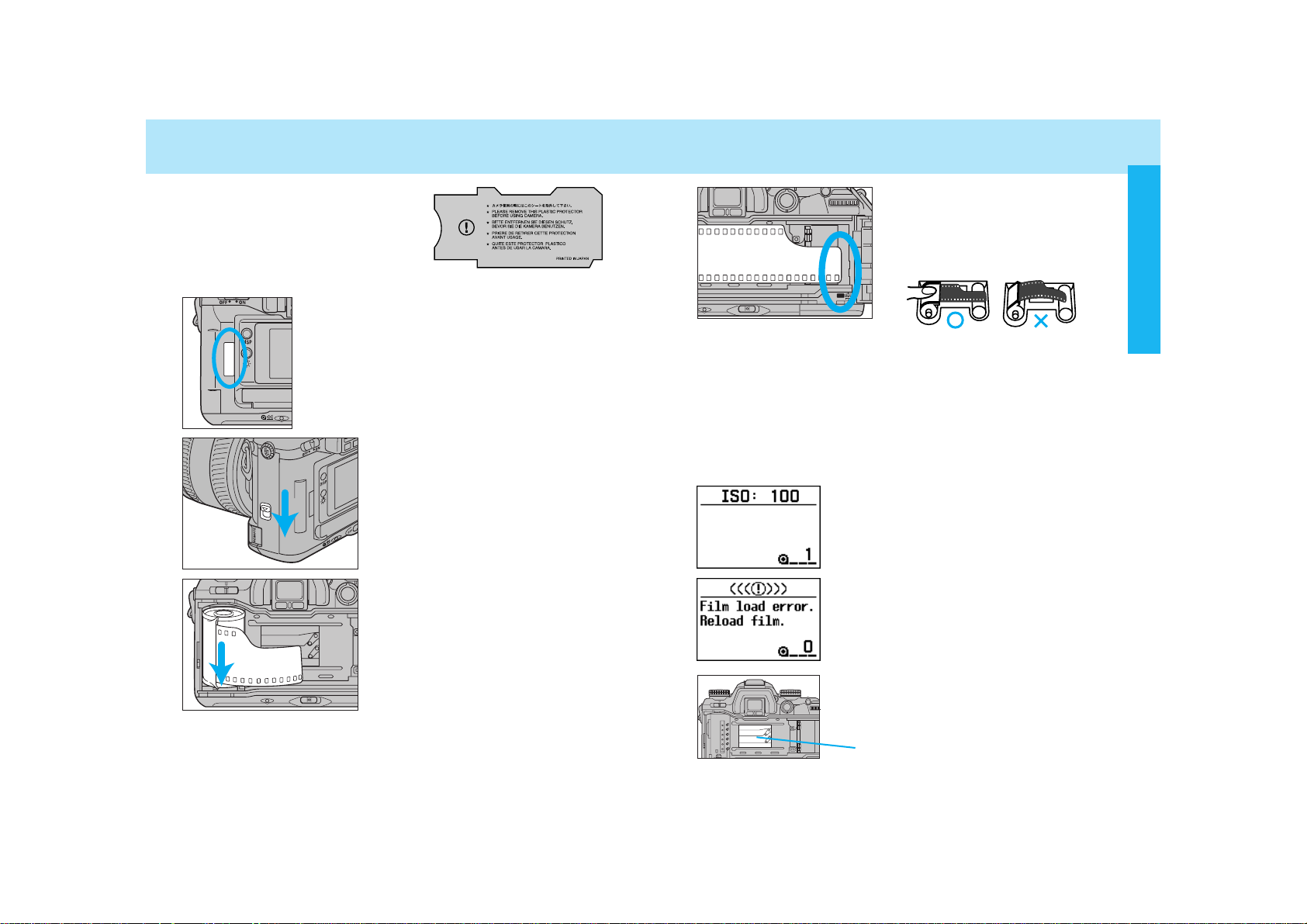
LOADING FILM
Check the film window before loading film. If
film is already loaded, refer to Manual Rewind
on page 34 to remove a partially exposed roll.
• Load film in the shade to reduce the chances of
fogging the film.
Remove and discard the protective
cover on the film gate before loading
film for the first time.
1. Slide the back-cover release
and open the back cover.
2. Insert film cartridge into the
film chamber.
• Refer to page 159 to reload a partially
exposed roll.
3. Extend the leader between the
guide rails to the index mark.
• If the film tip extends beyond the
index mark, push the excess film
back into the cartridge.
4. Close the back cover.
• The camera automatically advances
the film to the first frame. 1 will
appear in the frame counter.
• The ISO is shown in the navigation display
for 5 seconds after loading.
• If loading was unsuccessful, this message
appears in the navigation display. Repeat
steps 1-4.
shutter curtain
The shutter curtain’s precision design makes
it extremely sensitive to pressure. Never
touch it with your fingers or the film tip.
BASIC OPERATION
Page 12
2322
LOADING FILM
• Once the film is loaded, the back cover will lock until film rewinding is complete, preventing accidental opening.
• ISO is set automatically if DX-coded film is loaded. See page 86
for changing ISO manually.
• Non-DX-coded film is automatically rewound at the end of the roll
or after 36 exposures.
• Non-DX-coded film is set to the ISO from the previous roll. Refer
to page 86 to set the film speed manually.
• Do not use Polaroid Instant 35mm film. Winding problems may
occur.
• Do not use infrared film in this camera. The camera’s frame
counter sensor will fog infrared film.
HANDLING THE CAMERA
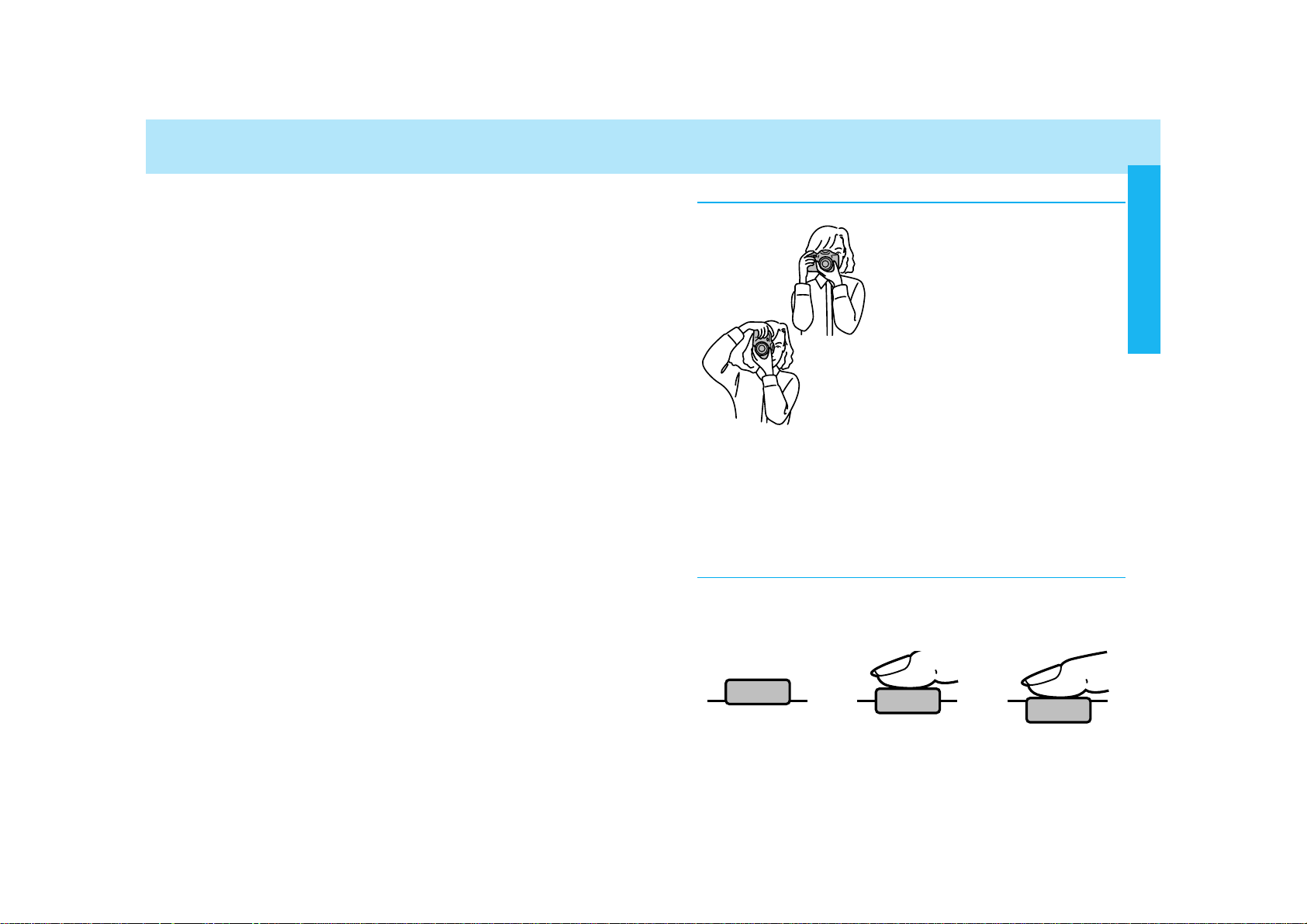
Holding the Camera
Grip the camera firmly with your right
hand, while supporting the lens with
your left. Keep your elbows at your
side and your feet shoulder-width
apart to hold the camera steady. Keep
the camera strap around your neck or
wrist in the event you accidentally
drop the camera.
• Do not touch the end of the lens
barrel while taking a picture.
• Do not block the AF illuminator.
• Use a tripod when using slow shutter
speeds or a telephoto lens.
• When taking vertically aligned photographs, the use of the vertical control grip, allows for easy access to all
camera functions.
Pressing the Shutter-Release Button
Press the shutter-release button partway down to activate the camera’s autofocus and auto-exposure systems. Gently press the shutter-release button all the way down to take the picture.
BASIC OPERATION
Page 13
2524
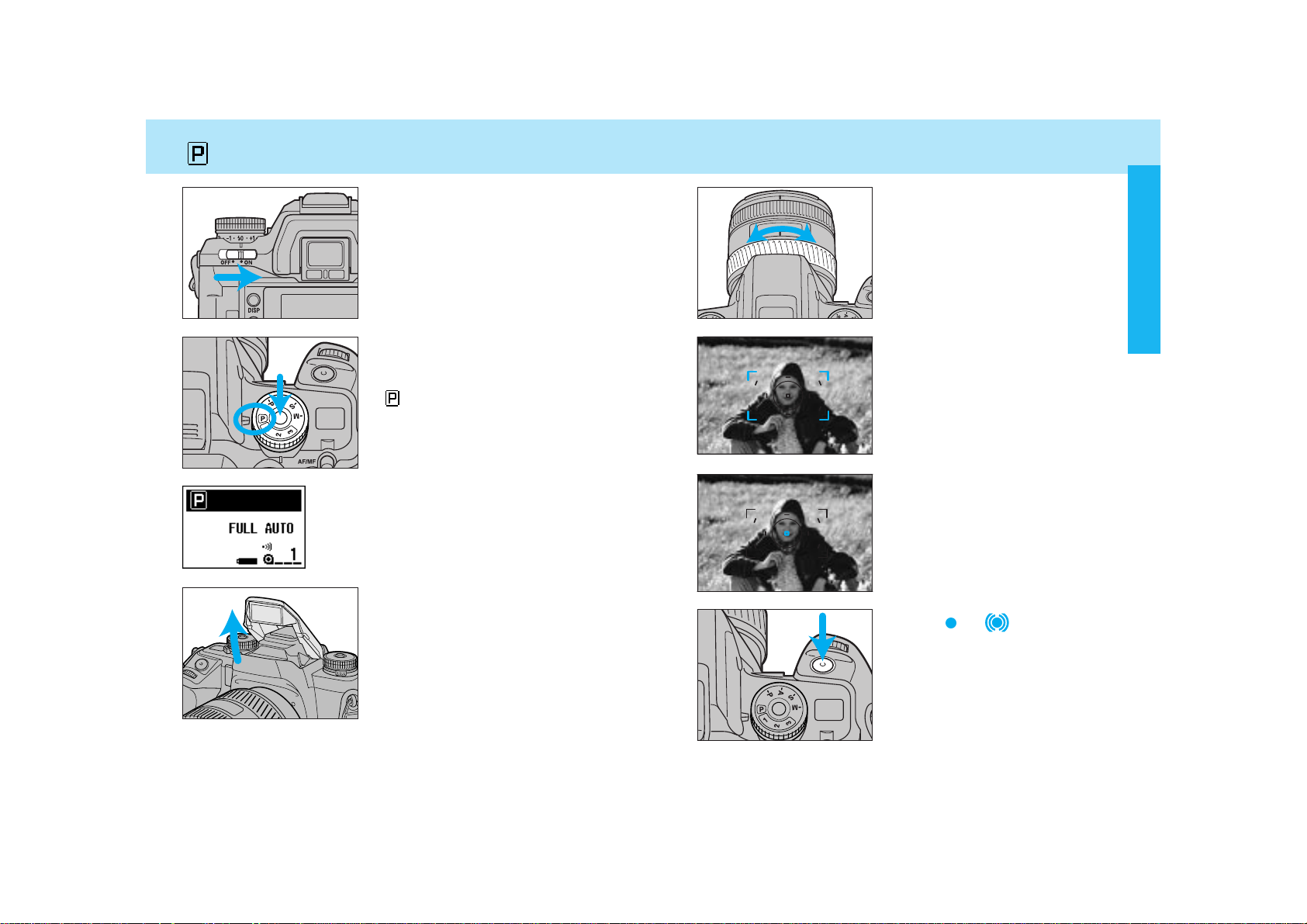
TAKING PICTURES IN FULL-AUTO
1. Turn the main switch to ON.
3. Raise the built-in flash.
• If the flash is raised, it will automatically fire when needed.
• For details on using the built-in flash,
see page 31.
2. While pressing the exposuremode dial lock-release button,
set the exposure-mode dial to
full-auto.
Full-auto is shown in the display. When the
upper part is black, as shown, the position of
the dials and levers may not match the actual
camera control.
4. If using a zoom lens, rotate the
zooming ring to frame your
subject as desired.
6. Press the shutter-release button partway down.
• Focus will be set automatically.
• Audio sounds and the local focus
area LED appears briefly indicating
the focus area selected by the camera.
7. When or appears in the
viewfinder, press the shutterrelease button all the way
down to take the picture.
• Use focus lock (p.29) if your subject
is outside the focus frame.
5. Center your subject in the
focus frame.
BASIC OPERATION
Page 14
2726
TAKING PICTURES IN FULL-AUTO
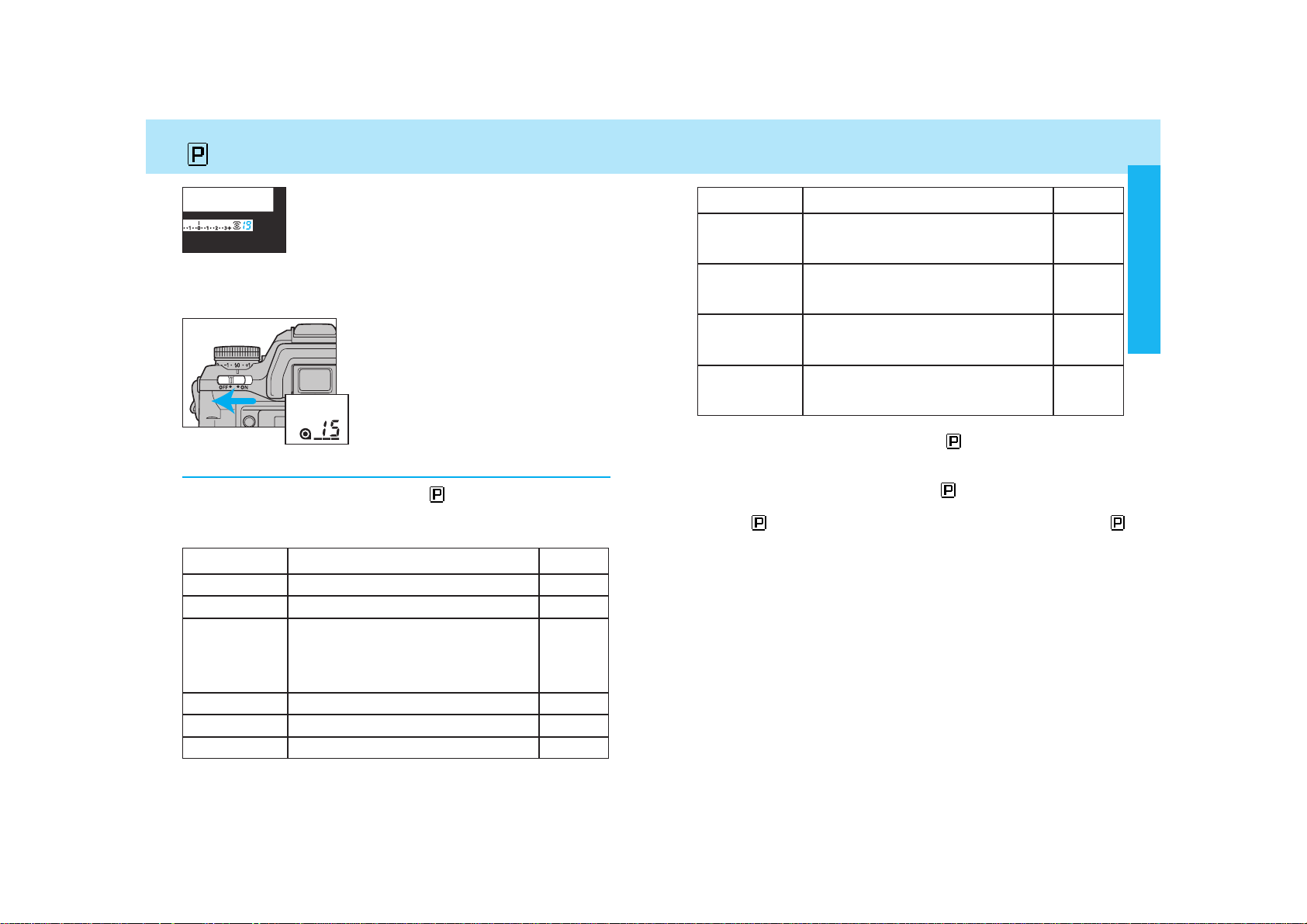
Full-Auto Basic Settings
When the exposure-mode dial is set to , the functions in the table
below are reset to the full-auto mode, and locked in order not to be
changed.
Function
Exposure mode
Metering mode
Flash mode
Focus mode
AF area
Full-Auto Settings
Program (P)
14-segment honeycomb-pattern
Autoflash, if the built-in flash is up.
(Pre-flash for red-eye reduction fires in
accordance with the position of the
flash-mode switch).
AF-A, Autofocus priority
Wide focus area
Page No.
61
74
99
46
54
Function
Exposure
compensation
Flash-metering
method
Full-Auto Settings
+/- 0.0EV
ADI (Advanced Distance Integration)
4-segment metering
Page No.
77
Flash
compensation
+/- 0.0EV 103
PA/PS creative
program mode
Cleared 62
108
• When the exposure-mode dial is set to , the functions in the table
above are reset to full-auto mode, and locked in order not to be
changed. However, if Custom 24-2 (p. 178) is selected, these settings
can be changed after the dial is set to .
• The following items will not be reset when the exposure-mode dial is
set to . Additional changes to these can be made after selecting
.
- Whether built-in flash fires or not
- Red-eye reduction
- Date and time imprinting
- Data memory
- Eye-start
- ISO setting
- Audio sound setting
- Custom function settings, except for custom functions 1, 20, 21, 22
and 23.
• The number of frames remaining is displayed in the
viewfinder for the last 19 frames on the roll. This
countdown does not appear for non-DX-coded film.
• After taking picture, turn the camera
off.
• After the camera is turned off, the
frame counter remains displayed in the
top data panel, but not in the rear navigation display.
• The frame counter in the top data
panel disappears when the main switch
is turned on.
• You can not take more pictures on a roll than what is stated on the
film cartridge.
• Audio sound can be canceled (p 131).
Drive mode Single frame advance 87
BASIC OPERATION
Page 15
2928
FOCUSING
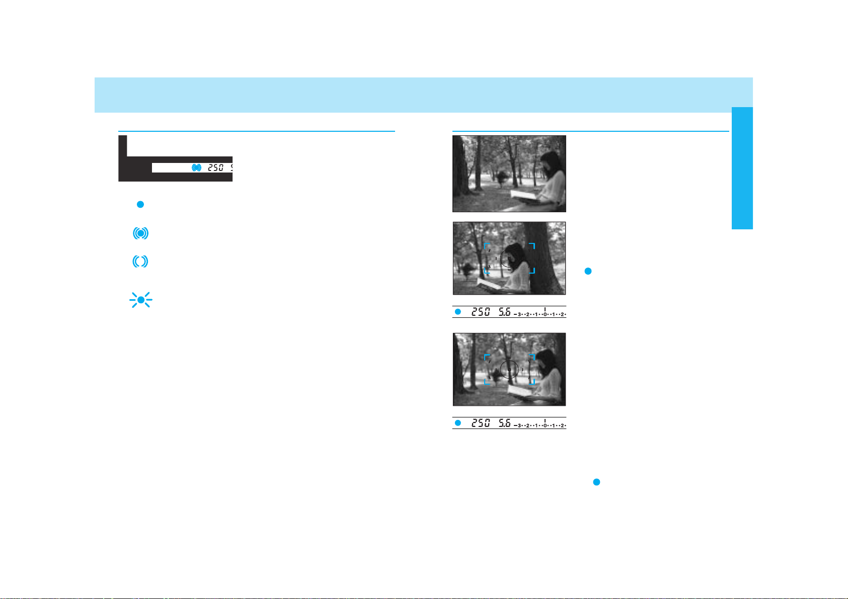
Focus Signals
The following signals appear in the
viewfinder to indicate the focus status
when the shutter-release button is
pressed partway down.
Focus is confirmed.
Continuous autofocus – Focus is confirmed.
Continuous autofocus – Lens focusing. Shutter is
locked.
(Blinks) Focus cannot be confirmed – Shutter is
locked.
Subject is too close or is one of the special focus situations described on page 30.
• In the above chart, the shutter is locked when the lens is focusing or
when focus cannot be confirmed. To change so that the shutter can
be released, even if focus has not been confirmed, select Custom1-
2.
• If eye-start is on, it is possible to activate focus by bringing the camera to your eye. See eye-start for more information (p. 125).
Focus Lock
Use focus lock when your subject is
outside the focus frame or when autofocus is difficult to confirm.
• The focus lock method described on
this page, is used for stationary subjects. For moving subjects, see page
47 .
1. Center your subject in the
focus frame, then press the
shutter-release button partway
down.
• appears in the viewfinder when
focus is confirmed.
• Focus lock also locks the exposure
settings when 14 segment honeycomb-pattern metering is selected (p.
74).
2. Continue to hold the shutterrelease button partway down
while you compose your picture.
3. Press the shutter-release button the rest of the way down to
take the picture.
• If the shutter-release button is raised partway up, focus lock will not
be cancelled. If you want the camera to refocus, remove your finger
from the shutter-release button.
• Focus lock is not possible unless appears in the viewfinder.
BASIC OPERATION
Page 16

3130
FOCUSING USING THE BUILT-IN FLASH
The built-in flash provides coverage for focal lengths as wide as
24mm.
1. Turn the main switch to ON
and set the exposure-mode
dial to .
2. Raise the built-in flash.
3. Press the shutter-release
button to take the picture.
• When the exposure mode dial is set to , the built-in flash will fire
only when necessary.
• For red-eye reduction, turn the flash-mode switch to the red-eye
reduction position.
• To cancel the flash, push the flash down.
The following signals appear in the
viewfinder to indicate the flash status
when the shutter-release button is
pressed partway down.
Flash is charged.
(Blinks) Previous exposure was correct.
Special Focus Situations
The camera may not be able to focus in situations like those
described below. When the focus signal blinks, use focus lock
(p. 29) or manual focus (p. 48). See page 28 for an explanation of
the focus signals.
If the subject within the
focus frame is very
bright, or low in contrast.
If two subjects at different distances overlap in the focus frame.
If a subject composed
of alternating light and
dark lines completely
fills the focus frame.
If your subject is near
a very bright object or
area.
Flash Signals
BASIC OPERATION
Page 17

3332
Automatic Rewind
The film is automatically rewound after the last frame is exposed.
1. Wait until the film is completely
rewound.
2. When the film is completely
rewound, open the back cover
and remove the film.
Flash Range
The range of the built-in flash depends on the speed of the film and
the selected aperture. Make sure your subject is within the flash
range specified in the table below.
Aperture ISO 100 ISO 200 ISO 400
f/2.8
f/3.5
f/4
f/5.6
1.0 ~ 4.3m 1.0 ~ 6.1m 1.0 ~ 8.6m
(3.3 ~ 14.1 ft.) (3.3 ~ 20.0 ft.) (3.3 ~ 28.2 ft.)
1.0 ~ 3.4m 1.0 ~ 4.8m 1.0 ~ 6.8m
(3.3 ~ 11.2 ft.) (3.3 ~ 15.7 ft.) (3.3 ~ 22.3 ft.)
1.0 ~ 3.0m 1.0 ~ 4.2m 1.0 ~ 6.0m
(3.3 ~ 9.8 ft.) (3.3 ~ 13.8 ft.) (3.3 ~ 19.7 ft.)
1.0 ~ 2.1m 1.0 ~ 3.0m 1.0 ~ 4.3m
(3.3 ~ 6.9 ft.) (3.3 ~ 9.8 ft.) (3.3 ~ 14.1 ft.)
Lens Shadowing
Lens shadowing occurs when the lens or lens hood blocks part of
the output from the built-in flash. Lens shadowing appears as semicircular shaded area at the bottom (horizontal) or side (vertical) of
your image.
• Make sure you are at least 1m (3.3 ft.) from your subject when using
the built-in flash.
• Remove the lens hood before using the built-in flash.
• Lens shadowing may occur with the following lenses at shorter focal
lengths.
AF Zoom 17-35mm f/3.5G AF Zoom 28-70mm f/2.8G
AF Zoom 28-85mm f/3.5-4.5 AF Zoom 28-135mm f/4-4.5
• The built-in flash can not be used with the following lenses:
AF 300mm f/2.8 (APO tele) AF 600mm f/4 (APO tele)
AF 300mm f/4 (APO tele)
• Do not open the back cover until this
message appears in the navigation
display. Never use force.
USING THE BUILT-IN FLASH REWINDING THE FILM
• If the manual rewind button is pressed while the film is rewinding, the
rewind speed will change.
BASIC OPERATION
Page 18

3534
REWINDING THE FILM
Manual Rewind
Use manual rewind to rewind the film before the roll is finished.
Gently press the manual-rewind
button.
• Use a blunt object. A sharp object may
cause damage.
Custom Function Notes
Custom 2, 3 and 12 refer to the rewinding of film.
Custom 2 - Automatic (1) or manually initiated (2) rewind start.
Custom 3 - Rewind the leader into the cartridge (1) or leave the
leader out (2).
Custom 12 - Fast (1) or slow/silent (2) rewind.
Once you have mastered the basic operation, you can move on to the Detailed
Operation section to expand your expertise.
Read those pages pertaining to the areas of
your interest and need.
DETAILED OPERATION
Navigation Display ................................36
Focusing ................................................45
Exposure...............................................60
Metering ................................................73
Drive......................................................87
Flash......................................................98
Additional Features..............................119
Memory Functions...............................132
Data Memory.......................................140
Custom Functions ...............................153
DETAILED OPERATION
DETAILED
OPERATION
Page 19
3736
Your camera uses the navigation display (a dot-matrix presentation in the
large LCD panel on the back of the
camera) to provide you with useful
photographic information.
• Only general information is included in this section. Please refer to
each specific section for more detailed information.
• Display will be slow in cold weather, but it normalizes when it
warms up.
• If the camera is not operated for more than 1 hour, with the main
switch on, the display will disappear. Press the shutter-release
button partway down, or turn the main switch off and then back
on, for the display to re-appear.
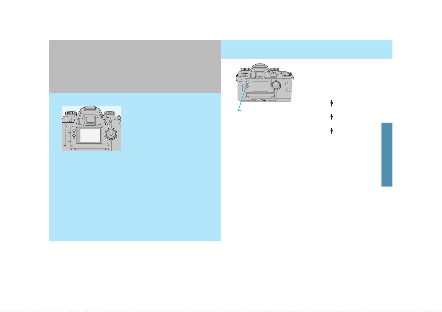
Exposure-history display
Display-selection button
When the camera is first turned on,
the detailed display is shown.
Pressing the display-selection button
causes the displays to change as follows:
• The horizontal detailed display is used for explanations throughout this
manual.
Detailed display
Large icon display
Meter-index display
DISPLAY SELECTION
NAVIGATION DISPLAY
NAVIGATION
DISPLAY
Page 20

3938
DISPLAY SELECTION
Detailed display Detailed display
Exposure-history
display
Meter-index display
Large icon display
Large icon display
Meter-index
display
Exposurehistory display
Display-selection button
Display-selection
button
Switch
horizontal/
vertical
Switch
horizontal/
vertical
Display selection button
Display-selection button
Display-selection button
Display selection
button
The detailed display shows all the settings.
• By selecting Custom 27-2 (p. 182), you can
show only those settings which differ from
the standard settings.
Detailed Display
For easier viewing of only a few items, select the large-icon display
option.
• To cancel this display, select Custom 29-2 (p. 184).
Aperture
Exposure compensation
Frame counter
Large Icon Display
Shutter speed
Exposure mode
Audio-on indicator
Battery condition
indicator
NAVIGATION DISPLAY
Display-selection button
Display-selection button
Page 21

4140
DISPLAY SELECTION
The meter index display shows the values of compensation and
bracketing that you have selected. The lower part shows compensation/bracketing with flash. The upper part of the display is shown
in both the viewfinder and the navigation display.
Meter-Index Display
Current exposure information
The metering index display contains the following:
Exposure compensation (p. 77)
Flash compensation (p. 103)
Metered manual value (p. 71)
Exposure bracketing (p. 92)
Flash bracketing (p. 104)
When AEL appears, EV difference between the AE locked and cur-
rent exposure value. (p. 83)
• To cancel this display, select Custom 30-2 (p. 185).
• or appears if the index is
more than +/- 3.0 EV.
Exposure-History Display
The exposure data for the next frame appears in the top of the display, followed by the those of the last 5 frames.
Exposure compensation
Next frame’s exposure data.
Previous 5 frames’ exposure data
Aperture
Shutter speed
• Displays present frame count.
• If there is no film in the camera, there will be no display.
• In this display, the imprint indicator , data memory ON indicator
and the audio indicator will not appear.
• After 5 exposures, whenever the shutter is released, the oldest
exposure data is deleted.
• For multiple exposures, the history shows the data of every exposure.
• Exposure-history is cleared by the replacement of the battery.
• To cancel this display, select Custom 31-2 (p. 185).
Top left part usually shows frame counter, but changes when multiple exposure drive mode or STF is selected:
, ..: When in multiple-exposure mode.
: When in STF mode.
NAVIGATION DISPLAY
Page 22

4342
DISPLAY SELECTION
When the exposure-mode dial is
turned to P ,A, S, or M, the upper part
of the display remains normal. But
when , 1, 2, or 3 is selected, the
upper part turns black.
Example 1: Exposure-mode dial set to P.
(Normal)
Example 2: Exposure-mode dial set to , fullauto mode. Top part of display has
turned black.
Example 3: Exposure-mode dial set to 1.
(memory setting). Top part of display has
turned black.
When the dial is set to full-auto or to one of the memory settings, the upper part of the display turns black and the position of
the dials and levers may not match the actual camera control. The
camera recalls the full-auto settings or the settings saved in the
selected memory function, and these are correctly shown on the
navigation display.
Vertical Display
Operation Display
• During the display’s 5 second period, pressing the shutter-release button partway down will return the display to the previous display.
• To cancel this display, select Custom 28-2 (p. 184).
The horizontal/vertical operation automatically changes the orientation of the navigation display, when the camera’s position is
changed to a vertical or horizontal position.
• Only the detailed and large-icon display are able to be displayed vertically. All others remain in the horizontal orientation.
• If you want the display to remain in the horizontal orientation, regardless of the camera’s position, choose Custom 32-2 (p. 186).
The operation display appears whenever you operate a camera dial
or function that is not currently on the display. The new settings will
appear for 5 seconds. When the detailed display has been selected, the operation display will not appear.
Example below shows the large icon display. When continuous
(high-speed) drive mode is selected, the display changes to the
operation display showing the new change, and then returns to the
large icon display 5 seconds later.
DISPLAY
(WHEN UPPER PART TURNS BLACK)
NAVIGATION DISPLAY
Page 23

4544
Your camera features complete
focus control, utilizing a newly
developed 9-point autofocus system with center dual cross-hair
sensors to give great flexibility
when composing photographs,
and the ability to switch between
AF and MF using the AF/MF control button without changing holding positions.
Display Illumination
Display Contrast
If desired, the display can be illuminated.
Press the navigation display illuminator.
• The display illuminator shuts off
approximately 5 seconds after the last
camera operation.
• If the button is pressed again before
the 5 seconds, it will shut off.
The contrast level of the display is adjustable.
• The contrast set display
appears.
• Turning the dial in the +
direction increases the
intensity.
• The contrast display will disappear when the shutter-release button is pressed partway down.
1. Press the display selection button for 3 seconds to select the
contrast set display.
2. Turn either the front or rearcontrol dial to adjust the contrast intensity.
The location of the film
plane is indicated by
the arrow.
DISPLAY BRIGHTNESS AND CONTRAST
FOCUSING
FOCUSING
Page 24

4746
FOCUS MODE
Continuous Autofocus (C)
Use continuous autofocus when shooting
sporting events or when you know the
subject will be in constant motion.
• The camera continues to focus as long as the shutter-release button is
pressed partway down.
• Audio doesn’t sound and the local focus area LED doesn’t appear in
the viewfinder in this mode.
Use single-shot AF when photographing
non-moving subjects or to lock focus on
subjects outside the focus area.
1. Turn focus-mode switch to C.
2. Press the shutter-release button partway down to activate
autofocus.
• appears in the display.
Single-Shot Autofocus (S)
Your camera has 3 autofocus modes plus manual focus. With the
camera set to other than , you can select one of the following
modes.
Automatic autofocus (A)
Continuous autofocus (C)
Single-shot autofocus (S)
Manual focus (MF)
Automatic Autofocus (A)
Designed to work well in almost any situation, automatic autofocus
is especially suited to moving subjects that stop suddenly. When the
subject is moving, continuous autofocus is set. When not moving,
single-shot autofocus is set.
1. Turn the focus-mode switch to
A.
2. Press the shutter-release button partway down to activate
autofocus.
• When the exposure-mode dial is set to , automatic autofocus is
set.
• Using custom functions, you can choose to select direct manual focus
(DMF) when the focus-mode switch is in the Aposition (p. 176).
• The camera will continue to focus as long as
the subject is moving,
then lock focus when
the subject is still.
• appears in the
display.
FOCUSING
Page 25

4948
FOCUS MODE
• appears in the viewfinder when the subject in the focus frame is in
focus.
• Even though manual focus has been selected, it is possible to utilize
autofocus by pressing the AF/MF control button (p. 51).
• When the focus ring doesn’t turn smoothly (for example when using a
teleconverter) see page 52.
• This camera uses distance information, even when in manual focus
mode, to obtain a proper exposure. In order to get precise information,
the focus position is at infinity when the camera’s main switch is
moved to the ON position.
2. Turn the focusing ring until
your subject appears sharp
and focused.
Pull and turn the zoom ring until your subject appears sharp.
AF Power Zoom and xi Series Lenses
1. Turn the focus-mode switch to
S.
2. Press the shutter-release button partway down to activate
autofocus.
Manual Focus (MF)
Focus the lens manually when autofocus is not suitable and focus
lock is not possible. The autofocus system will monitor focus and
indicate when a subject in the focus frame is in focus.
1. Turn the focus-mode switch to
MF.
• is displayed in both
the viewfinder and navigation display.
• appears in the display.
• Once confirmed, focus remains locked until your finger is removed
from the shutter-release button.
FOCUSING
Page 26

5150
AF/MF CONTROL BUTTON
In MF mode (focus-mode switch
set to MF), when the AF/MF control button is pressed, the MF
mode is switched to AF-S, autofocus is activated, and then focus
is locked.
• When you release the AF/MF control button, the camera returns to MF
mode, and now re-focusing is possible using the focusing ring.
• When the AF/MF control button is pressed, the camera will also meter
the subject.
• While pressing the AF/MF control button, disappears in the
viewfinder, but will remain in the navigation display.
• If Custom 9-2 is selected, autofocus and manual focus are automatically switched over by every push of the AF/MF control button, instead
of while pressing the AF/MF control button (p. 167).
AF to MF
In AF mode (focus-mode switch
set to C, A, or S), the AF mode is
switched to MF mode while
pressing the AF/MF control button.
• Turn the focusing ring while pressing
the AF/MF control button.
• will appear in the viewfinder while the AF/MF control button is
pressed. However, the AF-mode indicator in the navigation display
(AF-A, AF-C, AF-S) doesn’t change.
• If you don’t change the focus, the focus will remain locked while
pressing the AF/MF control button.
• If Custom 9-2 is selected, autofocus and manual focus are automatically switched over by every push of the AF/MF control button, instead
of while pressing the AF/MF control button (p. 167).
The AF/MF control button is located on the back allowing an instant
selection of focus mode with the right thumb without changing the
holding position.
• AF/MF control button cannot be used with xi series and AF Power
zoom lenses.
MF to AF
FOCUSING
Page 27

5352
FOCUS AREA
Wide focus area
Local focus area
The camera’s standard focus mode,
wide focus area, covers the entire
center area making it easier for the
camera to focus on moving subjects.
Nine sensors are located in the wide
focus area, which are shown by the
local focus area in the viewfinder.
When you press the shutter-release
button partway down, the camera
automatically decides which sensor to
be used, and the corresponding local
focus area LED lights in the viewfinder.
The local focus area mode also utilizes 9 point sensors, resulting in
greater flexibility when photographing
still objects. When you select any of
these local focus areas, the corresponding sensor is shown in the
viewfinder.
• When continuous autofocus (C) or automatic AF (A) with continuous
focus is selected, the local-focus area LED will not be illuminated in
the viewfinder.
• The display time of the local focus area can be selected by using
Custom 14 (p. 170).
The advance total focus control system has many advantages over
the conventional system. However, when used with certain lenses,
such as a teleconverter, the lens may have a heavier feel than conventional models, when focusing manually. If desired, users can
temporarily select a conventional manual focus operation.
1. Set the focus-mode switch
to MF.
2. Simultaneously press the
spot-AF button and lens
release.
3. Release your finger from
the lens release first, then
from the spot-AF button.
•
appears instead of the normal
.
• The AF/MF control button is inactive when the reversed
appears on the navigation display.
•
Some benefits, such as improved exposure metering and flashmetering accuracy in manual focus, will now be the same as with
a conventional camera.
• 14-segment honeycomb-pattern (p. 74) is changed to metering
similar to center-weighted averagewhen this option is selected.
• To return to the usual camera operation, set the focus-mode switch to
C, A, or S, or set the exposure-mode dial to full-auto.
• AF Power zoom and xi Series lenses cannot be used.
Smooth Focusing
FOCUSING
Page 28

5554
FOCUS AREA
2. Press the focus-area selector to focus using the wide
focus area. Press the spotAF button to use the center
spot-focus area.
• Viewfinder shows which sensor is
being used for focusing.
• While pressing the spot-AF button or
the focus-area selector, the focus is
locked.
3. While pressing either the focus-area selector or the spotAF button, press the shutter-release button and take the
picture.
• When the exposure-mode dial is set to , wide focus area is set.
• After taking the picture, as long as the spot-AF button or the focusarea selector remains pressed, focus remains locked, and additional
pictures may be taken.
• If 14-segment honeycomb-pattern is selected, the exposure is locked
when the focus is locked.
• When is selected, autofocus is not activated by pressing the
focus-area selector or the spot-AF button.
Choose the wide or local focus area as desired. By simply pressing
the spot-AF button, the center spot-focus area is selected.
Wide Focus Area
The camera automatically decides which
sensor to be used.
1.Set the wide/local focus-area
switch to wide.
• Wide focus area appears in the display.
FOCUSING
Page 29

5756
FOCUS AREA
• Viewfinder shows which sensor is
being used for focusing.
• While pressing the spot-AF button or
the focus-area selector, the focus is
locked.
3. While pressing either the focus-area selector or the spotAF button, press the shutter-release button and take the
picture.
• After taking the picture, as long as the spot-AF button or the focusarea selector remains pressed, focus remains locked, and additional
pictures may be taken.
• If you release your finger from the focus-area selector or the spot-AF
button, locked focus (position) is canceled, but local focus area
remains.
• If 14-segment honeycomb-pattern is selected, the exposure is locked
when the focus is locked.
• The same local focus area can be used to adjust focus (see p. 58).
• Only the center spot-focus area can be used with the AF Reflex
500mm f/8 lens and AF Power zoom 35-80mm, f/4-5.6.
Local Focus Area
Any one of the 9 local focus areas can be
selected.
1. Set the wide/local focus-area
switch to local.
• The local focus-area
appears in the navigation
display.
2. Press the focus-area selector
to select the local focus area
you want. Press the spot-AF
button to use the center spotfocus area.
FOCUSING
Page 30

5958
FOCUS AREA
In low-light/low subject contrast situations, the AF illuminator automatically
projects a pattern of lines onto the
subject for the camera’s AF sensors
to focus on.
• Do not to obstruct the AF illuminator.
• AF illuminator works for the center focus area only.
• The range of the AF illuminator is 0.7 – 7.0 meters (2.3 – 23.0 ft.).
• The AF illuminator will not fire in continuous autofocus mode.
• The AF illuminator may not operate with 300mm or longer single
focal length lenses.
• The AF illuminator will not operate with 3x-1x Macro Zoom.
• When an accessory flash is attached, its AF illuminator may be active
in place of the camera’s AF illuminator.
• AF illuminator can be canceled by Custom 21-2 (p. 176).
How to Lock the Local/Spot Focus Area
1. Turn the wide/local focus area
switch to local, and select the
focus area you want to lock.
2. Turn the wide/local focus-area
switch to lock.
• After taking the picture, the focus area remains locked.
• When the wide/local focus-area switch is locked, pressing the focusarea selector or the spot-AF button doesn’t activate the focus.
AF ILLUMINATOR
How to Lock the Wide Focus Area
1. Turn the wide/local focus area
switch to wide.
2. Turn the wide/local focus-area
switch to lock.
FOCUSING
Page 31

6160
EXPOSURE
Your camera’s exposure-mode dial has 8
positions;
Full-auto
P, A, S, and M modes
1, 2, and 3 memory modes
This section of the manual covers the P, A, S, and M modes.
• For the full-auto mode, see pages 24-27.
For memory modes, see page 132.
Select P mode (Programmmed AE) when you want to give your full
attention to your subject and composition. The P mode software
analyzes the subject’s size, motion, and magnification as well as the
focal length of your lens, then sets the shutter speed and aperture
according to the requirements of the scene.
1. While pressing the exposuremode dial lock-release button,
turn the exposure-mode dial to
P.
2 Compose your scene, focus,
and take the picture.
• When the shutter-release button is pressed
partway down, metering occurs and the shutter speed and aperture are shown on the navigation, top data panel, and viewfinder displays.
P MODE
Comparison of (full-auto) mode to P (program) mode:
In the (full-auto mode), all the camera settings are set automatically.
In the P (program mode), the camera sets the shutter-speed and
aperture, but all other camera settings are changeable.
EXPOSURE
Page 32

6362
P MODE A MODE
In Amode (aperture priority), you select the aperture and the camera automatically sets the shutter speed required for proper
exposure. Set the camera to Amode when you want to control the
range of focus (depth-of-field) in an image.
1. While pressing the exposuremode dial lock-release button,
turn the exposure-mode dial to
A.
• A appears in the navigation display.
• appears in the viewfinder, next to the aperture
display, indicating that the
aperture can be changed.
2. Turn either control dial to
select the aperture.
• The aperture setting changes in 1/2
or 1/3 EV increments depending on
the position of the exposure compensation dial. See page 77.
P
A
A
/P
/P
S
S
Mode
After the AE system has been activated, you can change the shutter
speed or aperture selected by the camera. Creative program remains
active until the display disappears.
Turn the front control
dial to change the
shutter speed.
• Aperture is adjusted
automatically.
Turn the rear control
dial to change the
aperture.
• Shutter speed is adjusted automatically.
While the aperture/shutter speed are displayed in P mode…
• The aperture and shutter speed change in 1/2 or 1/3 EV increments
depending on the position of the exposure compensation dial.
• Flash can not be used with the P
A and PS modes.
-Built-in and accessory flashes will not fire when the P
A and PS
modes are active.
-P
A and Ps modes can not be selected when the built-in flash is
up or the accessory flash is on.
• To cancel P
A / Ps mode, press the exposure-mode dial lock-release
button. It will also be cancelled 5 seconds after the display disappears, or immediately when the built-in flash is raised.
When the built-in flash is up or an attached accessory flash is on, it will
fire each time the shutter is released. The camera’s automatic flash
metering system will ensure proper exposure.
• Make sure your subject is within the flash range (p. 32).
P-Mode Flash
EXPOSURE
Page 33

6564
A MODE
The size of the aperture (lens opening) determines the depth-offield in the final image as well as the intensity of the light falling on
the film. Depth-of-field is the area in front of and behind the point
where the lens is focused which will appear sharp.
Large apertures (small f-numbers) limit the depth-of-field to a narrow range. Choose a large aperture if you want a defocused background so your main subject stands out, such as with portraits.
Small apertures (large f-numbers) provide greater depth-of-field.
Choose a small aperture when you want maximum focus range,
such as in a landscape photograph.
• In general, wider lenses provide more depth-of-field and longer
(telephoto) provide less depth-of-field.
• There is less depth-of-field when your subject is close to the lens.
Large Aperture
(small f-number)
Small Aperture
(large f-number)
Aperture Control
A-Mode Flash
1. Follow the steps on the previous page.
2. Raise the built-in flash, or turn the accessory flash on.
• appears in the viewfinder when the flash is charged.
• The shutter speed is automatically set to 1/200 or slower.
• When the built-in flash is up or an attached accessory flash is on, it
will fire each time the shutter is released. The camera’s automatic
flash metering system will ensure proper exposure.
• The use of a large aperture is recommended for a longer flash range.
• When pressing the shutter-release button partway down, if 200 blinks or the printing reverses,
the required setting is beyond the camera’s
shutter speed range. Turn the control dial until
the blinking/reversing stops.
• When pressing the shutter-release button partway down, i
f 8000 or 30” blinks or the printing
reverses, the required setting is beyond the
camera’s shutter speed range. Turn the control dial until the blinking/reversing stops.
EXPOSURE
Page 34

6766
S MODE
In S mode (shutter priority), you select the shutter speed and the
camera automatically sets the aperture for the proper exposure.
Use S mode when you want to control the blur caused by subject
movement.
1. While pressing the exposuremode dial lock-release button,
turn the exposure-mode dial to
S.
• S appears in the navigation display.
• appears in the viewfinder, next to the shutter
speed, indicating that the
shutter-speed can be
changed.
2. Turn either control dial to
select the shutter speed.
• The aperture setting
changes in 1/2 or 1/3 EV
increments depending
on the position of the
exposure compensation
dial. See page 77.
• When pressing the shutter-release button partway down, if the aperture value blinks or the
printing reverses, the required setting is beyond
the camera’s aperture range. Turn the control
dial until the blinking/reversing stops.
1. Follow the steps on the previous page.
2. Raise the built-in flash, or turn the accessory flash on.
• appears in the viewfinder when the flash is charged.
• Shutter speeds of 1/200 or slower can be selected. However, shutter
speeds greater than 1/200 can be achieved using high speed sync
5600HS(D), 3600HS(D), or 5400HS (p. 110).
• When the built-in flash is up or an attached accessory flash is on, it
will fire each time the shutter is released. The camera’s automatic
flash metering system will ensure proper exposure.
S-Mode Flash
• (Time exposure) should be used when in the M mode.
EXPOSURE
Page 35

6968
S MODE M MODE
Fast Shutter Speed Slow Shutter Speed
Because the shutter speed controls the duration of exposures, it
also determines how moving subjects will appear in the final image.
Use a slow shutter speed to blur the motion of your subject. Use a
fast shutter speed to stop the motion of your subject. In addition to
stopping action, fast shutter speeds can help prevent blur caused
by camera movement during the exposure.
Shutter Control
M mode (Manual) gives you full control of the exposure. The camera’s meter index displays how your settings compare to the
exposure determined by the camera’s metering system.
1. While pressing the exposuremode dial lock-release button,
turn the exposure-mode dial to
M.
2. Turn front control dial to select
the shutter speed.
3. Turn rear control dial to select
the aperture.
EXPOSURE
Page 36

7170
M-Mode Flash
1. Follow the steps on the previous page.
2. Raise the built-in flash, or turn the accessory flash on.
• appears in the viewfinder when the flash is charged.
• The shutter speeds of 1/200 or slower are selectable. However, shutter speeds greater than 1/200 can be achieved using high speed
sync flash 5600HS(D), 3600HS(D), or 5400HS (p. 110).
• When the built-in flash is up or an attached accessory flash is on, it
will fire each time the shutter is released. The camera’s automatic
flash metering system will ensure proper exposure.
Metering in M Mode
The meter index displays the EV difference between your settings and
the ‘correct’ exposure determined by the camera. The 0 position (null
point) represents the recommended exposure using the currently
selected metering pattern (pp.82-83). (Metered manual).
Your settings match the recommended exposure.
Your settings will overexpose the metered area by
1EV.
Your settings will overexpose the metered area by
1.3EV.
Your settings will underexpose the metered area by
1.5EV.
• The EV scale is marked in 1/2 or 1/3 EV increments depending on the
current setting of the exposure compensation dial (p. 77).
• or will blink in the meter index if
the settings will over or underexpose the subject by more than 3.0
EV.
• If you press the display-selection button, the
meter-index display appears in the navigation
display. Index in M mode (Metered manual) is
shown in the upper mid- area with .
M MODE
• appears in the viewfinder, next to the shutter-speed and aperture
display, indicating that both can be changed.
• The aperture setting changes in 1/2 or 1/3 EV increments depending
on the position of the exposure compensation dial.
EXPOSURE
Page 37

7372
M MODE
Manual Shift
Manual shift lets you shift to equivalent aperture/shutter speed combinations without changing the exposure value (EV).
1. Select a desired shutter speed
and aperture.
2. Press the AE-lock button and
turn the front control dial until
the desired aperture/shutter
speed combination appears in
the display.
• While pressing the AE-lock button, AELappears
in the viewfinder and appears in the navigation display.
• The operation of the AE-lock button can be changed by custom fucntion 10 (p. 168).
• When you select the 1/3 EV increments setting, the locked exposure
may change if the maximum aperture of 1/2 EV increments is chosen.
METERING
METERING
Page 38

7574
SELECTABLE METERING
Fourteen-segment honeycomb-pattern metering uses information from
the autofocus system to set the metering pattern according to the
position of the main subject. The light metered by each applicable
segment is then evaluated to determine the degree of spot-lighting or
backlighting present in your scene. The local focus-area (LED)
momentarily displays the sensor being used when the shutter release
button is pressed partway down.
Fourteen-segment honeycomb-pattern metering is the camera’s
standard metering mode and is appropriate for most photographic
situations.
14-Segment Honeycomb-Pattern Metering
Centered subject Subject on the right
Your camera takes meter readings of the light in the scene to determine the correct exposure. It has three methods of taking meter
readings. Use the method most appropriate for your subject.
Turn the metering-mode switch to
.
• appears in both the
viewfinder and navigation
display.
Spot Metering
Spot metering uses only the center honeycomb segment to meter the
image. The center honeycomb segment is shown by the spot metering
area in the viewfinder.
Turn the metering-mode switch to
.
• appears in both the
viewfinder and navigation display.
METERING
Page 39

7776
Center-Weighted Average Metering
Center-weighted average mode bases the exposure on an average of
the readings from each of the honeycomb segments - with emphasis
placed on the center of the image.
Care should be taken when photographing backlit, spotlighted, or offcenter subjects, as non-subject areas may be included in the exposure
calculation.
• appears in both the
viewfinder and navigation
display.
Turn the metering-mode switch to
.
Especially helpful when using the spot or center weighted metering
patterns, exposure compensation lets you manually adjust the
metered exposure +/– 3 EVs in 1/2 or +/– 2 EVs in 1/3 EV increments. This function is especially useful when shooting with slide
film, because of the film’s low tolerance for exposure error.
Under exposure
Proper exposure
Over exposure
• Dial is locked only when you go from the 0.0 compensation setting.
• Select Custom 18 (p. 173) to change the exposure compensation
value using the rear control dial in P, A, and S modes.
• Selected compensation
value appears in the navigation display.
While pressing the exposurecompensation dial lock-release
button, turn the exposure-compensation dial to the desired
compensation value.
SELECTABLE METERING EXPOSURE COMPENSATION
METERING
Page 40

7978
EXPOSURE COMPENSATION
Changing to 1/3 Increments
1. Set the exposure-compensation
dial to the edge of the 1/2EV
increment (ie; +/-3.0EV).
2. While pressing the exposurecompensation dial lock-release
button, turn the exposure-compensation dial to the edge of the
1/3EV increment (ie; +/- 2.0EV).
1/3EV increment 1/2EV increment
Example below shows changing from 1/2EV to 1/3EV increment.
• When going from 1/3EV increment to 1/2EV increment, use the same
procedure as described in steps 1 and 2 above.
• If you select 1/3EV increment, aperture, shutter speed, and the value
on the meter index will change to 1/3EV increment.
• If 1/3EV increments are selected, the lens’ maximum/minimum aperture may not appear correctly, but the camera will be set correctly.
Exposure compensation
value of -1.5
(1/2EV increment)
Exposure compensation
value of +1.3
(1/3EV increment)
• If you press the display-selection button, the
meter-index display appears in the navigation
display. Exposure compensation index is shown
in the upper mid-area with .
Meter Index
The meter index displays the exposure compensation value you set.
METERING
Page 41

8180
EXPOSURE COMPENSATION AUTOMATIC EXPOSURE LOCK (AEL)
Press the AE-lock button to lock the exposure using the currently
selected metering pattern without locking the focus. The exposure
remains locked until the AE-lock button is released.
1. Select the desired metering
pattern (pp. 74-76), and focus
on subject.
• appears in the
viewfinder and navigation
display.
• Meter index also appears in
the viewfinder (p. 83).
2. Press and hold the AE-lock
button.
1. For exposure compensation, when the flash doesn’t fire, the picture will be compensated by changes in both the shutter speed and
the aperture.
2. For exposure compensation, when the flash does fire, compensation will be due to changes in shutter speed, aperture, and the
flash burst.
3. For flash compensation, only the flash burst changes.
• Specifically for 1 and 2 above, when in;
P-mode - both shutter speed and aperture change.
A-mode - only the shutter speed changes.
S-mode - only the aperture changes.
• See page 103 for additional information regarding flash compen-
sation.
• If you desire a fixed flash burst for exposure compensation with
flash, select Custom 26-2 (p. 181).
Comparison between exposure compensation and flash
compensation.
3. While pressing the AE-lock
button, recompose the scene
as desired.
4. While still pressing the AElock button, press the shutterrelease button all-the-way
down to take the picture.
METERING
Page 42

8382
AUTOMATIC EXPOSURE LOCK (AEL)
• If you keep pressing the AE-lock button after taking the picture, the
exposure remains locked.
• Pressing the AE-lock button sets the flash to slow-shutter sync mode
(p. 102).
• If Custom 10-2 is selected, pressing the AE-lock button once activates
automatic exposure lock. Pressing again cancels.
Meter Index When AE-Lock Button is Pressed
The meter index displays the EV difference between the locked
exposure and the exposure for the subject area currently inside the
spot-metering area. Using the AE-lock button function, you can
compare the difference between the locked (actual) exposure and
the exposure in each part of the image. If the difference is more
than +2.3EV, that part of the picture will be washed out. If the difference is more than -2.7EV, the picture will be dark and the details
will be gone. Depending on the type of film, these values may
change. Without taking the picture, you can measure the brightness
and predict the results.
Spot Metering
Example: Recompose the picture from to , while pressing the
AE-lock button.
21
Press AE-lock button .
1
Keep pressing AE-lock button
while recomposing picture .
2
14-Segment Honeycomb-Pattern and Center-Weighted
Average Metering
Press AE-lock button .
1
Keep pressing AE-lock button
while recomposing picture .
2
*Locked exposure will always be 0EV unless exposure compensation is
set.
Locked exposure value (0EV)*
Locked exposure value (0EV)*
Exposure currently in the spot-metering area
Exposure in the spot-metering area
METERING
21
Page 43

• If more than 3.0EV, only + or - will appear, instead of a value.
• Press the display-selection button once again to cancel the brightness-distribution display while still pressing the AE-lock button.
• If you release your finger from the AE-lock button, both brightness distribution and locked exposure will be canceled.
• Shutter speed, aperture, and exposure compensation appear in the
top portion of the display.
• If a non-displayed setting is changed, the operation display appears.
• This feature is useful for monitoring which areas of the picture are
under or over-exposed, and allows the user to also confirm the variation on the brightness distribution with the exposure-compensation
dial.
• If bracketing is selected, the normal position (+/- 0) of the bracketing
series will be displayed in the brightness-distribution display.
• Brightness-distribution display shows values without flash. When flash
fires, displayed values may be slightly lower than the values without
flash.
• The EV scale is marked in 1/2 or 1/3EV increments depending on the
current setting of the exposure copmensation dial (p. 77-78).
8584
AUTOMATIC EXPOSURE LOCK (AEL)
Brightness-Distribution Display
While pressing the AE-lock button, press the display-selection
button. Each segment will be
shaded and a value indicated.
• The shading appears as;
White : +1EV or more.
Gray : when between -1EV and +1EV.
(No value given when gray)
Black : -1EV or less.
The display shows the difference between the
locked value “0” and the output from each of
the 14-honeycomb segments.
• If you press the display-selection button, the
meter-index display appears in the navigation
display. When you press the AE-lock button,
the index shows the differences between the
locked exposure and the exposure currently in
the spot-metering area.
• The EV scale is marked in 1/2 or 1/3EV increments depending on the
current setting of the exposure compensation dial (p. 77).
• or will blink in the meter index if the settings will over or underexpose the subject by more than 3.0EV.
Shutter speed Aperture
Difference is between -1EV
and +1EV.
2EV under
Exposure compensation
3 EV over
the locked
value.
METERING
Page 44

8786
SETTING THE ISO MANUALLY
Continuous drive, exposure bracketing, multiple exposures, and
other options can be selected using the drive-mode lever.
The standard drive-mode setting for this
camera is single-frame (drive-mode lever
set to ).
The selectable modes are represented
by;
(Single-frame advance)
(Continuous advance)
Bracketing
S (Single frame advance)
C (Continuous advance)
Self-timer
Multiple Exposure
Set the ISO manually to override the DX-coded ISO or when using nonDX coded film.
• Film must be loaded before the ISO can be changed.
• Non-DX coded film is initially set to the previous roll’s ISO.
1. Open the control-panel door
and press the ISO button.
• The current ISO is shown
in the display.
• The ISO can be changed
manually from 6 to 6400 in
1/3 EV increments.
2. Turn either control dial to set
the desired ISO value.
3. Press the shutter-release button partway down to enter the
new ISO.
Custom 4-2 DX Memory ON (p. 164).
Applies ISO changes to future rolls with the same DX-coded ISO.
• The drive-mode lever can not be changed while pressing the
exposure-mode dial lock-release button.
DRIVE
DRIVE
Page 45

8988
CONTINUOUS
This camera has both single-frame and continuous advance drive
modes. Select single-frame advance to expose and advance the
film one frame at a time. Switch to continuous drive to photograph
dynamic action sequences at up to 4 frames per second in high
speed mode (3.7 when AF-Aor AF-C is selected) or 2 frames per
second in low speed mode.
1. Turn the drive-mode lever to the
desired drive mode.
- Single-Frame Advance
- Continuous Advance
2. Open the control-panel door,
then press the adjust button.
• The display will switch to the
setting display.
3. Turn either control dial to
select high or low speed continuous drive.
4. Keep pressing the shutter-release button to take the pictures.
• The high or low setting will remain selected until you change it.
• When the built-in flash is up or an accessory flash is on, the shutter
can not be released until the flash is charged.
• The shutter can not be released until the camera has focused on your
subject.
• If AF-S (Single-shot autofocus) is selected, focus will be locked until
the series of continuous frames is finished.
• Return the drive-mode lever to to cancel the continuous drive
mode.
• AF Zoom xi and Power zoom lenses cannot be zoomed when
continuous-advance mode is selected.
• When the battery power is low or in low temperatures, the maxi-
mum drive speed may temporarily drop. Continued operation with
low battery power may even cause a complete stoppage.
• Press the shutter-release button partway down
to enter the setting. HI remains for high continuous, LO remains for low continuous
mode.
If continuous advance is selected...
DRIVE
Page 46

9190
SELF-TIMER
Use the self-timer to delay the shutter release for 2 or 10 seconds
(approx.) after the shutter-release button is pressed all the way
down. In addition to delaying release of the shutter, the 2 second
delay pops the mirror up two seconds before the shutter opens to
reduce blur caused by camera vibration.
• Attach the eyepiece cap (p.127) when there is a bright light source
behind the camera.
1. Place the camera on a tripod,
then turn the drive-mode lever
to
.
• Self-timer set display
appears.
4. Center your subject in the
focus frame, then press the
shutter-release button partway
down to confirm the focus.
5. Press the shutter-release button all the way down to start
the timer.
• 10 seconds (10 s) –The self-timer lamp on the front of the camera
will blink slowly, then blink rapidly just before the shutter releases.
• An audio sound will also be heard for the 10 second self-timer. It can
be canceled if desired (p. 131).
• Turn the camera off or select another drive mode to cancel the 10
second self-timer.
• 2 seconds (2 s) –The mirror pops up when the shutter-release button
is pressed all-the-way down. The shutter is released two seconds
later.
• The 2 second self-timer cannot be cancelled.
• The red-eye reduction flash mode is not effective when the 2 second
self-timer is selected.
2.
Open the control panel door
and press the adjust button.
3. Turn either control dial until the
desired delay appears in navigation display.
• Press the shutter-release button partway down
to enter the setting.
2s remains for 2 second
delay,
10s remains for 10 second delay.
DRIVE
Page 47

9392
EXPOSURE BRACKETING
Exposure bracketing automatically exposes a series of frames with
exposures above and below the metered exposure value. Bracket
your exposures when shooting slides and other films with a low tolerance for exposure error. A larger bracketing increment is recommended when shooting negative film.
• This camera can expose a 3, 5, or 7 frame brackets in increments of
0.3, 0.5, 0.7, or 1.0 EV.
1. Turn the drive-mode lever to
the desired bracketing mode.
S - Single Frame Advance
C - Continuous Advance
2. Open the control-panel door,
then press the adjust button.
• The current bracketing increment and
size of the bracket is shown in the
display.
3. Turn the front control dial to
set the bracketing increment
(0.3, 0.5, 0.7, 1.0 EV).
4. Turn the rear control dial to
set the size of the bracket (3,
5 or 7 frames).
• Press the shutter-release button partway down
to enter the setting. remains for single
frame advance, remains for continuous
frame advance mode.
5. Compose (and meter) your subject, then press the shutter-release button all the way down to start the bracketing.
• In S - Single-frame advance, press the shutter-release button for
each exposure.
• In C - Continuous advance, hold the shutter-release button until
the series is finished.
Exposure-bracketing indicator
Front-control-dial
indicator
Meter index
Rear-control-dial
indicator
DRIVE
Page 48

9594
EXPOSURE BRACKETING
When bracketing is selected, the meter index appears in the
viewfinder.
• If exposure compensation is also selected, the whole bracketing
series will be shifted.
• Meter index doesn’t appear in the viewfinder while adjusting the increment and size of the bracketing.
• Every time the picture is taken, the corresponding bar will disappear.
• To cancel, move the drive-mode lever to a different mode.
• The normal sequence (for a 5 frame bracket in 1/2 increments) is;
Normal ➝ -0.5EV ➝ +0.5EV ➝ -1.0EV ➝ +1.0EV
However by selecting Custom 11-2, the following sequence is possible; (p 169.)
-1.0EV ➝ -0.5EV ➝ Normal➝ +0.5EV ➝ +1.0EV
• Exposure is locked on the first frame of the series.
• P mode (programmed autoexposure) exposures are bracketed by
changing both the aperture and shutter speed.
• S (shutter priority) mode and P
S mode exposures are bracketed by
changing the aperture.
• M mode (manual), A mode (aperture priority) and P
A mode exposures
are bracketed by changing the shutter speed.
• Press the AE-lock button when the shutter is released to bracket using
the aperture in manual (M) mode.
Single Frame Advance
• The number above the bracket indicator in the display and also in the
viewfinder, increases each time you take a picture.
• Film can be changed in the middle of the bracketed series.
• Turn the camera off, or select another drive mode to cancel single
frame advance bracketing.
Continuous Advance
• Removing your finger from the shutter-release button before the series
is complete resets the camera to the first frame of the bracket.
• Continuous advance bracketing is cancelled at the end of the roll.
Meter Index
Bracketing increment - 0.7EV
Size of bracket - 3 frames
Bracketing increment - 0.5EV
Size of bracket - 5 frames
Exposure compensation - +1.0EV
• If a 1/2EV exposure increment is selected with a 0.3 or 0.7EV
exposure bracketing increment, or if a 1/3EV exposure increment is
selected with a 0.5EV exposure bracketing increment, then the position of the bar in the meter index shown in the viewfinder will be slightly shifted. However, the exposure will be exactly as set.
• If you press the display-selection button, the
meter-index display appears in the navigation
display. Exposure bracketing index is shown in
the upper mid-area with .
Dial setting only. The actual bracketing value may
not be as indicated in the reverse printed area.
Actual exposure values for the previous 5 exposures.
With the exposure history display, the next exposure value is reversed
printed to tell you that camera setting is different.
DRIVE
Page 49

97
96
MULTIPLE EXPOSURE
The meter in your camera determines exposure (EV) based on the
assumption that only one exposure will be made on each frame.
When making multiple exposures, the EV for each additional
exposure may need to be reduced or over exposure can result.
Compensate the exposures as follows:
Number of
Exposures
Exposure
Adjustment
123468
0 -1 -1 1/2 -2 -2 1/2 -3
• The above corrections are intended as a general guideline. Some
testing may be necessary to produce the desired results.
• Compensation may not be necessary if all of the exposures have dark
backgrounds and the subjects of the exposures will not overlap.
• Exposure can be compensated in 1/2 or 1/3 EV increments using the
exposure compensation function (p. 77).
• The camera can be turned off and back on during a multiple exposure
series.
• When date/time imprinting is selected, the date/time will be printed
when the film is wound.
• When using negative film, tell your photofinisher there are multiple
exposures on the roll. Some photofinishers may not automatically print
multiple exposure.
• If Custom 3-2 is selected, you can partially rewind the film and overlap
an exposure on a previously exposed frame (p. 161-163).
1. Turn the drive-mode lever to
.
The multiple exposure function makes
it possible to expose 2 or more
images on the same frame.
• appears in the display’s
frame counter.
2. Compose the scene, then press the shutter-release button all the way down to take the first exposure.
• After the first exposure, appears in the display and is reverse printed telling you that the
next exposure will be overlapped.
• Take additional exposures as desired.
• Additional exposures are counted only up to
, but an unlimited number of exposures can
be taken.
• The number on the also increases up to 9.
3. Select another drive mode to cancel multiple exposure
mode and to advance the film to the next frame.
DRIVE
Page 50

9998
Red-eye reduction (p. 100) Normal flash
Normal flash (p. 31) Normal flash
REAR
Rear flash sync (p. 101) Rear flash sync (p. 101)
WL
Wireless/remote flash (p.112)*
Normal flash
Built-in flash Program Flash
This section of your manual covers the operation of accessory
flashes as well as the built-in flash.
The high accuracy of your camera’s flash metering is realized by
ADI (Advanced Distance Integration) flash metering in combination
with the newly developed D flash units and D lenses. Flash metering is controlled by the guide number in addition to pre-flash metering. Compared with the conventional TTL flash metering, flash output is less influenced by the background conditions or the subject’s
reflectance in ADI flash metering, offering optimum flash metering.
Your camera’s built-in flash provides coverage for a 24mm angle of
view, with a flash guide number of 12.
ADI flash metering
Conventional TTL metering
Built-in flash - Raise the built-in
flash.
Accessory flash - Turn the
accessory flash on.
Flash pictures can be taken using the built-in flash or with separately sold accessory flash units.
• The flash-mode switch has four positions.
• In full-auto mode, the flash will automatically fire when necessary.
will appear in the navigation display.
• When you are not in full-auto mode, the flash will fire every time.
will appear in the navigation display.
* If you use the built-in flash with the flash-mode switch set to WL, the
exposure will not be correct.
FLASH MODE SWITCH
FLASH
FLASH
Page 51

101100
RED-EYE REDUCTION REAR FLASH SYNC
With rear flash sync Without rear flash sync
Slow sync flash exposures can appear unnatural because the
motion blur precedes the subject in the final image. Use rear flash
sync to create more natural looking slow shutter speed flash exposures that leave a blur of motion behind the subject.
1. Raise the built-in flash, or turn
the accessory flash on, and
turn the flash-mode switch to
REAR .
• Flash synchronization returns to front sync (standard operation) when
shutter speeds faster than 1/60 are selected.
• Rear flash sync cannot be used with red-eye reduction or wireless
flash.
1. Raise the built-in flash and turn
the flash-mode switch to .
• appears in the navigation display.
2. Press the shutter-release button to take the picture.
• Warn your subject that the flash will
fire a few short bursts just before the
picture is taken.
• Red-eye reduction can only be used
with the built-in flash.
• Red-eye reduction is not effective
when used with self-timer, mirror lockup function (p. 90).
When photographing people or animals at night or in other low-light
situations, the effect called red-eye may occur due to the flash
reflecting off the inside of the subject’s eyes. To reduce this effect,
the flash fires a series of small bursts before the main flash burst.
This causes the subject’s pupils to close, greatly reducing the
amount of light which will reflect off the retina.
2. Press the shutter-release button to take the picture.
• appears in the
display.
FLASH
Page 52

103102
Slow-shutter sync Conventional flash
In P and A-modes, slow-shutter sync sets a slower shutter speed to
increase the background or ambient exposure in a flash picture. Flash
output is automatically decreased to maintain correct subject exposure.
1. Raise the built-in flash or turn
the accessory flash on.
2. While pressing the AE-lock button, press the shutter-release
button all the way down to take
the picture.
• AEL and the locked exposure will be displayed
in the display and the viewfinder.
• The shutter speed may not be reduced if the
background is bright or a large aperture is set
(A-mode).
• Use a tripod if the shutter speed becomes too
slow to allow sharp, hand-held pictures.
• Custom 10-2 lets you press the AE-lock button
once to activate slow-shutter sync. Press again
to cancel (p. 168).
Use flash compensation to increase or decrease the output of the
built-in or an attached accessory flash up to +/–2 EV in 1/2EV increments. This function is especially useful when shooting with slide
film, because of the film’s low tolerance for exposure error.
Flash compensation changes the flash exposure by the amount set
relative to the ambient exposure.
Rotate the flash-compensation
dial to the desired compensation
value.
• Selected compensation
values appear in the navigation display.
• appears in the
viewfinder.
• Flash compensation does not modify the output of a flash set to manual flash or connected to the PC terminal.
• Flash compensation has no effect on the ambient light exposure.
• Flash compensation and exposure compensation can be used together. See page 80 for their comparison.
• Over exposure, using flash compensation, may not be possible with
the built-in flash.
• If you press the display-selection button, the
meter-index display appears in the navigation
display. The flash compensation index is shown
in the lower mid-area with .
SLOW-SHUTTER SYNC FLASH COMPENSATION
FLASH
Page 53

105104
FLASH BRACKETING
Flash bracketing lets you expose a series of frames with exposures
below and above the normal metered exposure while using flash.
You can choose a series of 3, 5, or 7 frame flash exposure brackets
in 0.3, 0.5, 0.7, or 1.0 EV increments. Exposures are bracketed by
controlling the flash output.
• A larger bracketing increment is recommended when shooting negative film.
1. Raise the built-in flash or turn the accessory flash on.
2. Turn the drive-mode lever to
single-frame advance ( S) or
continuous-frame advance
( C) bracketing mode.
• The shutter-release button must be
pressed for each exposure, even
when the lever is in the (C) position.
3. Open the control-panel door,
then press the adjust button.
• The set display appears in the navigation display.
Flashbracketing
indicator
Front control dial
Meter index
Rear control dial
4. Turn the front control dial to
set the bracketing increment
(0.3, 0.5, 0.7, 1.0 EV).
5. Turn the rear control dial to set
the size of the bracket (3, 5 or 7
frames).
6. Compose your subject and press the shutter-release button all the-way-down to take the picture.
7. Repeat step 6 until the series is complete.
• Turn the camera off, change the drive mode, push the built-in flash
down to cancel the bracketed series.
• Press the shutter-release button partway down
to enter the settings. or remains in the
display while flash bracketing is set.
FLASH
Page 54

107106
• The normal sequence (for a 5 frame bracket in 1/2 increments) is;
Normal ➝ -0.5EV ➝ +0.5EV ➝ -1.0EV ➝ +1.0EV
However by selecting Custom 11-2, the following sequence is possible; (p 169.)
-1.0EV ➝ -0.5EV ➝ Normal➝ +0.5EV ➝ +1.0EV
• The number above the bracket indicator in the display and also in the
viewfinder, increases each time you take a picture.
• Film can be changed in the middle of the bracketed series.
• Bracketing towards overexposure may not be possible with the built-in
flash.
• If you press the display-selection button, the
meter-index display appears in the navigation
display. The flash bracketing index is shown in
the lower mid-area with .
• Your camera comes with
an accessory shoe cap
which protects the
accessory shoe contacts.
When using a flash or
other accessory, remove
the accessory shoe cap
(1) and store the shoe
cap into the eyepiece cap
for safekeeping (2).
21
By using an optional accessory flash, such as the 5600HS(D), you
can get improved flash performance over the built-in flash. The
accessory flash units fit in the shoe located on the top of your camera.
• The flash signals for the accessory flash are the same as those for the
built-in flash (p. 31).
• Refer to the specific instruction manual for each accessory flash to
obtain the flash range. For the 5600HS(D), 5400HS, and 5400xi, the
flash range will also appear in their data panels.
FLASH BRACKETING ACCESSORY FLASH
FLASH
Page 55

109108
Flash metering changes according to the flash unit and lens being
used.
5600HS(D)
3600HS(D)
ADI metering
(HSS on, with pre-flash)
Pre-flash metering
(HSS on)
Built-in flash
ADI metering
(without pre-flash)
TTL metering
5400HS
Pre-flash metering
(HSS on)
Pre-flash metering
(HSS on)
Other accessory
flashes
TTL metering TTL metering
D lens Other lenses
• When the shutter speed is faster than 1/200 sec, flash metering will
be HSS-TTL. If Wireless/Remote flash is set, metering will be
Wireless/Remote-TTL.
When using an accessory flash with HSS function, and if HSS is
turned on, then pre-flash fires and ADI/Pre-flash metering will occur
(blue area of the chart ). When using a D lens, ADI metering is
also done using the built-in flash ( area).
• TTL 4-segment flash metering will be used instead of ADI/Pre-flash
metering, when HSS is off, bounce flash is set, or when an off-camera
cable is used to connect multiple flash units. TTL average metering
will be used instead of ADI/Pre-flash metering when rear flash or the
mirror lock-up function is selected.
TTL metering (Through-the-lens):
The TTL flash metering system determines the flash
exposure automatically.
Pre-flash metering:
A pre-flash fires before the main exposure. The preflash is
metered (14 segment) and fed back to the flash exposure
system to more accurately determine the flash exposure.
ADI metering (Advanced Distance Integration):
Flash metering is controlled by the guide number in addition to TTL metering. Flash output is less influenced by the
background conditions or the subjects reflectance.
When pre-flash fires, a flash/color meter cannot meter accurately.
This is because the purpose of pre-flash is to assist ADI/Pre-flashmetering, not to provide illumination for the picture. Cancel HSS
(see flash manual) or eliminate the influence on metering using
Custom 20-2/3 (p. 175). Those items affected are in in the
chart on page 108. However, if you use the test-flash button on the
flash, the pre-flash will not fire.
Use of a Flash/Color Meter with Pre-Flash
When Using a Close-up Diffuser, Certain Filters and Lenses
When close-up diffuser CD-1000, or a filter whose stop’s increase is
not 0 (i.e., ND) is used, or when the focus-range limiter or macro
release of certain lenses are used, the proper exposure will not be
obtained by ADI or Pre-flash metering. For those items in
(p. 108),
cancel the HSS or choose Custom 20-2/3. When using the built-in flash
,
you must choose Custom 20-2/3 .
• Custom 20 gives you the choice of (1) ADI 4-segment flash metering,
(2) TTL 4-segment flash metering, (3) TTL average flash metering (p.
175).
FLASH METERING
FLASH
Page 56

111110
HIGH-SPEED SYNC
The maximum sync speed for this camera is 1/200. However, with the
5600HS(D), 5400HS, and 3600HS(D) accessory flashes (sold
separately) shutter speeds up to 1/8000 can be used. High-speed sync
(HSS) allows faster shutter speeds when fill flash is used on moving
subjects outdoors. HSS also lets you use large aperture/high shutterspeed combinations to separate your subject from the background by
limiting the depth-of-field.
Attach the 5600HS(D), 5400HS or 3600HS(D) and set it to
HSS mode.
High-speed sync Conventional-fill flash
• When using flash and color meters, high-speed sync is not possible.
Turn the flash’s HSS off or use a shutter speed of 1/200 second or
slower.
• Shutter speeds faster than 1/200 second are not available when the 2
second self-timer or rear flash sync has been selected.
• automatically appears in the viewfinder and
the navigation display at shutter speeds faster
than 1/200 sec when the 5600HS(D), 5400HS,
or 3600HS(D) is attached.
FLASH
Page 57

113112
Wireless/Remote Flash is available
with the Minolta 5600HS(D), 5400HS,
3600HS(D), 5400xi, and 3500xi
accessory flashes. Wireless/Remote
flash lets you experience the creative
control available with an accessory
flash.
In Wireless/Remote flash mode, the
off-camera flash is triggered by a
coded signal from the camera’s builtin flash when you press the shutterrelease button. When proper
exposure has been received, another
signal cuts the accessory flash off.
You can also achieve a 2:1 lighting
ratio automatically. When remote ratio
flash is selected, the off-camera flash
provides 2/3 of the full exposure while
the built-in flash provides the remaining 1/3.
Normal Flash
Wireless/Remote Ratio Flash
Wireless/Remote Flash
1. Attach the accessory flash to
the camera, then turn the camera and the flash on.
2. Turn the flash-mode switch to
WL.
• The wireless set display
appears in the navigation
display.
3. Turn either control dial and
select normal wireless or ratio.
• Normal Wireless : When selected, only the accessory flash fires.
• Ratio: When selected, the built-in flash will provide 1/3 and the
accessory flash will provide 2/3 of the total exposure.
WIRELESS/REMOTE OFF-CAMERA FLASH
FLASH
Page 58

115114
WIRELESS/REMOTE OFF-CAMERA FLASH
4. Press the shutter-release button partway down.
• Navigation display returns to the previous display.
• WL appears in the display.
5. Detach the accessory flash,
then raise the built-in flash.
Flash-Subject
Distance
Camera-Subject
Distance
The off-camera flash may not
detect the control signals if it is
placed behind the subject.
The maximum flash-subject
distance is 5m.
6. Position your camera and flash unit using the information
on this page.
• Wireless/Remote flash is most effective when used in dark or poorly
lighted areas.
• Refer to your flash instruction manual for more detailed flash to sub-
ject distance information.
Shutter
speed
Aperture
2.8
4
5.6
All shutter
speeds
1.4 - 5m
4.6 - 16 ft.
1 - 5m
3.3 - 16 ft.
1 - 5m
3.3 - 16 ft.
- 1/60
1.4 - 5 m
4.6 - 16 ft.
1 - 5 m
3.3 - 16 ft.
1 - 5 m
3.3 - 16 ft.
1/60 1/200
1- 5 m
3.3 - 16 ft.
1 - 5 m
3.3 - 16 ft.
1 - 5 m
3.3 - 16 ft.
1/250
1 - 5 m
3.3- 16 ft.
1 - 3.5m
3.3 - 11.5 ft.
1 - 2.5m
3.3 - 8 ft.
1/1000
1 - 2.5 m
3.3 - 8 ft.
1 - 1.7m
3.3 - 5.5 ft.
1 - 1.2 m
3.3 - 3.9 ft.
Non HSS HSS
• The table above is for ISO 100 film. Distance will be double if you are
using ISO 400 film (maximum 5m/16 ft).
• HSS is possible only with D flash.
Flash - subject
Camera -
subject
• WL appears in the viewfinder.
FLASH
Page 59

117116
WIRELESS/REMOTE OFF-CAMERA FLASH
7. Wait until both flash units are
fully charged.
• appears in the viewfinder when the
built-in flash is charged.
• When the off-camera flash is
charged, its AF illuminator will blink.
8. Press the AE-lock button to test
fire the accessory flash.
• Caution; Test firing the flash will activate slow-shutter sync (p. 102) if
Custom 10-2 (p. 168) is selected.
Custom setting 10-1 is recommended.
• If unsuccessful, change the position of
the camera or the flash.
9. Press the shutter-release but-
ton all the way down to take
the picture.
• There is no limit for shutter speed when using 5600HS(D)/3600HS(D)
in normal wireless, as these have high-speed sync capability in wireless/remote off camera flash mode. However, in wireless ratio mode or
when using 5400HS, 5400xi, or 3500xi in wireless/remote flash mode,
the shutter speed should be 1/60 second or slower.
Using 2 accessory flashes with one
(5600HS(D), 5400HS, or 5400xi)
attached to the camera acting as the
controller, the other accessory flash
acting as an off-camera flash.
Using a Wireless/Remote Flash
Controller as the controller, and one
or more accessory flash as an offcamera flash.
1. Attach the accessory flash to the camera, and turn both
the camera and flash on.
2. Turn the flash-mode switch to a position other than WL.
Canceling the Wireless/Remote Flash
Additional Wireless/Remote Flash Options
Wireless/Remote Flash Using more than one flash
Wireless/remote flash with two or more accessory flashes is also
possible. If you use both a D series flash and a non-D series flash,
attach a non-D flash to the camera and set wireless mode.
Otherwise, the non-D flash doesn’t fire.
In addition to the procedure described on p. 112-116, where the
built-in flash acts as the controller, there are two other ways in
which wireless/remote flash can be used;
Switching Between Normal WL Flash and Ratio WL Flash
1. Turn flash-mode switch to a position other than WL and
then back to WL.
2. The wireless set display appears in the navigation display. Select normal or ratio-flash by turning either the
front or rear control dial.
FLASH
Page 60

119118
PC TERMINAL
Flash units which can not be connected to the accessory shoe can be connected to the camera via the PC terminal.
• Set the exposure mode dial to M.
• Set the shutter speed to 1/200 or slower.
• The flash unit may fire unexpectedly if it is on when the sync. cord is
plugged into the PC terminal.
• TTL flash metering does not function when the flash is connected to
the PC terminal.
• Flash compensation is not possible. However, flash bracketing is possible if you press the AE-lock button while taking a picture.
• The PC terminal is compatible with both center positive (normal polarity) and center negative (positive polarity) flash units.
• When using the PC terminal, rear flash sync can not be used.
ADDITIONAL FEATURES
ADDITIONAL
FEATURES
Page 61

121120
DATE/TIME IMPRINTING
No printing Date printing
Time printing
Setting the Date/Time
The Quartz-data function lets you record the
date or time onto the lower left-hand corner
of the photograph. The automatic calendar is
good through the year 2039.
Approximate location
of print area.
1. Open the control-panel door
and press the DATE button.
• The display changes as follows;
• When you press the shutter-release button
partway down, the display returns to the previous display.
• If the printing option is selected, or
remains in the navigation display.
• “M” appears over the month.
1. Open the control-panel door
and press the DATE button.
• The date imprint window
appears in the navigation
display.
• If the camera batteries are removed for a long period of time, the
date/time may have to be reset.
• Imprinted data may be difficult to read if the lower left area of the photograph is bright or non-uniform.
• Printing intensity can be changed using Custom 33 (p. 186).
• Imprinting may not be done or it may be overlapped on the last frame
of a roll.
• The sequence of the date off, date on, and time imprint displays can
also be controlled using the fcus-area selector.
2. Turn the front or rear control
dial to select the date you
want.
ADDITIONAL FEATURES
Page 62

123122
DATE/TIME IMPRINTING
6. After all items are set, press the shutter-release button
partway down. The normal display returns.
4. Turn the rear control dial to
change the value.
3.Turn the front control dial to
selected the item you wish to
change.
When appears at the top right side, it is
possible to use the focus-area selector instead
of the dial.
If you press the right/left side
of the selector, the high-lighted
area moves.
If you press the top/bottom
side of the selector, the highlighted value changes.
• Display returns to normal when you press the shutter-release button
partway down.
After the camera batteries have been installed for two days, a
second battery (non-accessable) will have been charged. This
second battery will be able to provide power to retain the
date/time settings for approximately 6 months should the camera’s batteries be removed. After that, this message appears and
the date/time information will not be imprinted, and must be set. See pages 121-122 for
instructions for setting the date and time.
2. Press the ADJ button.
• The date adjust window appears and the
year is high-lighted.
5. Repeat steps 3 and 4 until the correct date/time is set.
ADDITIONAL FEATURES
Page 63

125124
DATE/TIME IMPRINTING
Using Eye-Start
1. Slide the eye-start switch to
ON.
2. Turn the main switch to ON.
• The grip sensor is activated.
3. Touching the grip sensor activates the eyepiece sensor.
• Autofocus and exposure systems shut down approx. five seconds
after eye or grip sensor contact is broken.
• Eye-start may not work properly when using a tripod, gloves, or if your
hands are dry. In these cases, press the shutter-release button partway down to activate focus and metering.
• Infrared absorbing sunglasses may affect eye-start operation.
• Choose Custom 7- 2 to activate the eyepiece sensor when the main
switch is in the ON position (ie; grip sensor is not used) (p.166).
Eye-start automatically activates the
camera’s focus and exposure systems
as you bring the camera to your eye.
When an object is detected near the
viewfinder, the camera’s systems are
activated to set the focus and
exposure as you frame your subject.
4. When an object is detected near the viewfinder, the cam-
era’s systems are activated to set the focus and exposure
as you frame your subject.
Changing the Format
The order of the year/month/day can be changed.
1. Open the control-panel door
and press the DATE button.
3. Turn either the front or rear
control dial to select the
desired format.
2. Hold the ADJ button for 3 seconds. The year, month, and day
will appear high-lighted.
4. Press the shutter-release button partway down to save
the desired format.
• The date imprint window will appear in the
navigation display.
EYE-START
Grip Sensor
Eyepiece sensor
ADDITIONAL FEATURES
Page 64

127126
TIME EXPOSURES (BULB)
ADDITIONAL FEATURES
• To reduce camera blur, attach a remote cord (p. 191).
5. Cover the viewfinder with the
eyepiece cap.
• The eyepiece cap prevents light from
entering through the viewfinder and
affecting the metered exposure.
6. Press and hold the shutterrelease button to take the picture.
• During the time exposure, the exposure time will
be shown on the navigation display.
4. Compose your picture.
• If the scene is too dark for autofocus to operate, turn the focus-mode
switch to MF and focus the lens manually (p. 48).
3. Turn the rear control dial to
select the aperture.
Set the shutter speed to bulb when
you want to take time exposures.
When selected, the shutter remains
open as long as the shutter-release
button is held down.
• Mount the camera on a tripod.
1. While pressing the exposuredial mode dial lock-release button, turn the exposure-mode
dial to M.
2. Turn the front control dial until
BULB appears in the navigation display.
Page 65

129128
When focus point is near infinity
When using a D lens, and the depth-of-field preview button is
pressed, the following information is presented in the navigation display.
Shutter speed, aperture,
exposure compensation
Will be shown if magnification is greater than
1:10 when using a D macro lens.
If the D.O.F. is less than 0.01m , appears.
If more than 20m (66ft), appears.
If near infinity,
∞
appears.
Front depth-offield
Rear depth-of-field
• If blinks or glows in the viewfinder (ie; focus not confirmed),
then the shutter cannot be released.
The magnification ratio is the ratio of the actual size of an object to
the size of its image on the film plane.
If an object is actually 12 mm in size, and the image is also 12mm
in size, then the magnification ratio is 1:1. If the image size is 6mm,
then the magnification ratio is 1:2.
When the lens is focused on a subject, there is a range behind and
in front of the subject that appears sharp. This is the depth-of-field.
To check how much of your scene will appear in focus, press the
depth-of-field preview button. The lens is stopped down to the aperture that appears in the display.
Depth-of-field can be increased by:
1. Using smaller apertures (larger f-=stop numbers).
2. Using short focal length (wider angle) lenses.
3. Moving farther away form your subject.
Range in focus
Aperture
Press the depth-of-field preview
button.
• The lens will stop down to the currently
selected aperture.
• The viewfinder will appear darker at
larger f#s (smaller lens opening).
• The aperture can be changed while
the depth-of-field preview button is
pressed.
• If you press the depth-of-field preview button after pressing the shutterrelease button partway down, the shutter can still be released.
• Cancel by removing your finger from the depth-of-field preview button.
Large
Small
DEPTH-OF-FIELD PREVIEW
ADDITIONAL FEATURES
Page 66

131130
DIOPTER ADJUSTMENT
• When audio ON is selected, a tone will be heard when;
Focus is confirmed - 2 short beeps, except when the subject is
moving, or when AF-C is set.
Self-timer countdown - will beep slowly at first, then rapidly, and
finally a solid tone just before the shutter releases.
1. Open the control-panel door
and simultaneously press the
ADJ and CUSTOM buttons.
2. Turn either the front or rear
control dial to select audio ON
or OFF.
• The audio set display will
appear.
• The navigation display returns to the previous
display when the shutter-release button is
pressed partway down. appears when audio
is selected.
Your camera has the capability of producing an audio tone to let
you know when focus is confirmed and locked. It can also sound
when using the self-timer mode.
SETTING/CANCELLING THE AUDIO
ADDITIONAL FEATURES
• It may be easier to adjust if
the eyepiece cup is removed.
Farsighted users – turn the
dial clockwise.
Nearsighted users – turn the
dial counter-clockwise.
Turn the diopter-adjustment dial
until the focus frame appears
sharpest.
• For easier adjusting, before attaching the lens, look through the
viewfinder at a well illuminated blank wall or clear blue sky.
• If additional correction is needed, attach a Minolta Eyepiece Corrector
(optional accessory) to the camera’s eyepiece. There are 4 types
available for near sighted and 5 types for far sighted vision.
Turn the diopter adjustment dial to compensate the eyepiece for
near or far sighted vision problems. The adjustment range is from
–2.5 to + 0.5 diopters.
 Loading...