

Page 1

SERVICE MANUAL
Models
7145/7222/7228/7235
APRIL 2004
CSM-7145/7222/7228/7235
KONICA MINOLTA BUSINESS SOLUTIONS U.S.A., INC.
Page 2

Page 3

7145/7222/7228/7235
SERVICE MANUAL
APRIL 2004
Page 4

IMPORTANT NOTICE
Because of the possible hazards to an inexperienced
person servicing this equipment, as well as the risk of
damage to the equipment, Konica Minolta Business
Solutions U.S.A., Inc. strongly recommends that all
servicing be performed by Konica Minolta-trained service technicians only.
Changes may have been made to this equipment to
improve its performance after this service manual was
printed. Accordingly, Konica Minolta Business Solutions
U.S.A., Inc., makes no representations or warranties,
either expressed or implied, that the information contained in this service manual is complete or accurate. It
is understood that the user of this manual must assume
all risks or personal injury and/or damage to the equipment while servicing the equipment for which this service manual is intended.
Corporate Publications Department
© 2004, KONICA MINOLTA BUSINESS SOLUTIONS U.S.A. , INC.
All rights reserved.
Printed in U.S.A.
Page 5

CONTENTS
CONTENTS
SAFETY AND IMPORTANT WARNING ITEMS . . . . . . . . . . . . . . . . . . . . . . . . . . . . . . . . . . . . . . . . . . . . S-1
IMPORTANT NOTICE . . . . . . . . . . . . . . . . . . . . . . . . . . . . . . . . . . . . . . . . . . . . . . . . . . . . . . . . . . . . . . . S-1
DESCRIPTION ITEMS FOR DANGER, WARNING AND CAUTION . . . . . . . . . . . . . . . . . . . . . . . . . . . . S-1
SAFETY WARNINGS . . . . . . . . . . . . . . . . . . . . . . . . . . . . . . . . . . . . . . . . . . . . . . . . . . . . . . . . . . . . . . . . S-2
SAFETY INFORMATION . . . . . . . . . . . . . . . . . . . . . . . . . . . . . . . . . . . . . . . . . . . . . . . . . . . . . . . . . . . . . S-10
IMPORTANT INFORMATION . . . . . . . . . . . . . . . . . . . . . . . . . . . . . . . . . . . . . . . . . . . . . . . . . . . . . . . . . S-10
SAFETY CIRCUITS . . . . . . . . . . . . . . . . . . . . . . . . . . . . . . . . . . . . . . . . . . . . . . . . . . . . . . . . . . . . . . . . S-11
INDICATION OF WARNING ON THE MACHINE . . . . . . . . . . . . . . . . . . . . . . . . . . . . . . . . . . . . . . . . . . S-13
List of major differences between the 7145, 7235, 7228 and 7222 . . . . . . . . . . . . . . . . . . . . . . . . . . . . . . . . 1
List of options corresponding to the 7145/7235/7228/7222 . . . . . . . . . . . . . . . . . . . . . . . . . . . . . . . . . . . . . . 3
I OUTLINE
1. OUTLINE OF SYSTEM . . . . . . . . . . . . . . . . . . . . . . . . . . . . . . . . . . . . . . . . . . . . . . . . . . . . . . . . . . . . 1-1
2. PRODUCT SPECIFICATIONS . . . . . . . . . . . . . . . . . . . . . . . . . . . . . . . . . . . . . . . . . . . . . . . . . . . . . . . 1-3
A. Type. . . . . . . . . . . . . . . . . . . . . . . . . . . . . . . . . . . . . . . . . . . . . . . . . . . . . . . . . . . . . . . . . . . . . . . . 1-3
B. Functions . . . . . . . . . . . . . . . . . . . . . . . . . . . . . . . . . . . . . . . . . . . . . . . . . . . . . . . . . . . . . . . . . . . . 1-3
C. Copy paper . . . . . . . . . . . . . . . . . . . . . . . . . . . . . . . . . . . . . . . . . . . . . . . . . . . . . . . . . . . . . . . . . . 1-5
D. Machine data. . . . . . . . . . . . . . . . . . . . . . . . . . . . . . . . . . . . . . . . . . . . . . . . . . . . . . . . . . . . . . . . . 1-5
E. Maintenance . . . . . . . . . . . . . . . . . . . . . . . . . . . . . . . . . . . . . . . . . . . . . . . . . . . . . . . . . . . . . . . . 1-5
F. Consumables. . . . . . . . . . . . . . . . . . . . . . . . . . . . . . . . . . . . . . . . . . . . . . . . . . . . . . . . . . . . . . . . . 1-5
G. Operating environment . . . . . . . . . . . . . . . . . . . . . . . . . . . . . . . . . . . . . . . . . . . . . . . . . . . . . . . . . 1-6
3. CENTER CROSS SECTION . . . . . . . . . . . . . . . . . . . . . . . . . . . . . . . . . . . . . . . . . . . . . . . . . . . . . . . . 1-7
4. DRIVE SYSTEM DIAGRAM . . . . . . . . . . . . . . . . . . . . . . . . . . . . . . . . . . . . . . . . . . . . . . . . . . . . . . . . . 1-8
4.1 Drum drive. . . . . . . . . . . . . . . . . . . . . . . . . . . . . . . . . . . . . . . . . . . . . . . . . . . . . . . . . . . . . . . . . . . 1-8
4.2 Cleaning/Developer agitation drive . . . . . . . . . . . . . . . . . . . . . . . . . . . . . . . . . . . . . . . . . . . . . . . . 1-8
4.3 Fixing/Paper exit section/IT-101/RU-101 drive . . . . . . . . . . . . . . . . . . . . . . . . . . . . . . . . . . . . . . . 1-9
4.4 Developing drive . . . . . . . . . . . . . . . . . . . . . . . . . . . . . . . . . . . . . . . . . . . . . . . . . . . . . . . . . . . . . . 1-9
4.5 Paper feed drive . . . . . . . . . . . . . . . . . . . . . . . . . . . . . . . . . . . . . . . . . . . . . . . . . . . . . . . . . . . . . 1-10
4.5.1 Drive from paper feed motor to loop clutch . . . . . . . . . . . . . . . . . . . . . . . . . . . . . . . . . . . . 1-10
4.5.2 Tray 1 drive . . . . . . . . . . . . . . . . . . . . . . . . . . . . . . . . . . . . . . . . . . . . . . . . . . . . . . . . . . . . 1-11
4.5.3 Tray 2 drive . . . . . . . . . . . . . . . . . . . . . . . . . . . . . . . . . . . . . . . . . . . . . . . . . . . . . . . . . . . . 1-11
4.5.4 Bypass feed drive . . . . . . . . . . . . . . . . . . . . . . . . . . . . . . . . . . . . . . . . . . . . . . . . . . . . . . . 1-12
4.5.5 Registration clutch drive . . . . . . . . . . . . . . . . . . . . . . . . . . . . . . . . . . . . . . . . . . . . . . . . . . . 1-12
4.6 ADU drive . . . . . . . . . . . . . . . . . . . . . . . . . . . . . . . . . . . . . . . . . . . . . . . . . . . . . . . . . . . . . . . . . . 1-13
4.7 Scanner drive . . . . . . . . . . . . . . . . . . . . . . . . . . . . . . . . . . . . . . . . . . . . . . . . . . . . . . . . . . . . . . . 1-14
4.8 Toner supply drive . . . . . . . . . . . . . . . . . . . . . . . . . . . . . . . . . . . . . . . . . . . . . . . . . . . . . . . . . . . . 1-15
I OUTLINEII UNIT EXPLANATIONIII DIS./ASSEMBLY
i
2
Page 6

CONTENTS
I OUTLINEII UNIT EXPLANATIONIII DIS./ASSEMBLY
II UNIT EXPLANATION
1. SCANNER SECTION . . . . . . . . . . . . . . . . . . . . . . . . . . . . . . . . . . . . . . . . . . . . . . . . . . . . . . . . . . . . . . 2-1
1.1 Composition . . . . . . . . . . . . . . . . . . . . . . . . . . . . . . . . . . . . . . . . . . . . . . . . . . . . . . . . . . . . . . . . . . 2-1
1.2 Operation . . . . . . . . . . . . . . . . . . . . . . . . . . . . . . . . . . . . . . . . . . . . . . . . . . . . . . . . . . . . . . . . . . . . 2-2
1.2.1 Initial operation when power is turned on and shading correction reading. . . . . . . . . . . . . . 2-2
1.2.2 Original reading mode . . . . . . . . . . . . . . . . . . . . . . . . . . . . . . . . . . . . . . . . . . . . . . . . . . . . . 2-2
1.2.3 Original read control . . . . . . . . . . . . . . . . . . . . . . . . . . . . . . . . . . . . . . . . . . . . . . . . . . . . . . . 2-4
1.2.4 APS control. . . . . . . . . . . . . . . . . . . . . . . . . . . . . . . . . . . . . . . . . . . . . . . . . . . . . . . . . . . . . . 2-5
1.2.5 AE control . . . . . . . . . . . . . . . . . . . . . . . . . . . . . . . . . . . . . . . . . . . . . . . . . . . . . . . . . . . . . . . 2-7
1.2.6 Image processing . . . . . . . . . . . . . . . . . . . . . . . . . . . . . . . . . . . . . . . . . . . . . . . . . . . . . . . . . 2-8
2. WRITE UNIT . . . . . . . . . . . . . . . . . . . . . . . . . . . . . . . . . . . . . . . . . . . . . . . . . . . . . . . . . . . . . . . . . . . . . 2-9
2.1 Composition . . . . . . . . . . . . . . . . . . . . . . . . . . . . . . . . . . . . . . . . . . . . . . . . . . . . . . . . . . . . . . . . . . 2-9
2.2 Operation . . . . . . . . . . . . . . . . . . . . . . . . . . . . . . . . . . . . . . . . . . . . . . . . . . . . . . . . . . . . . . . . . . . 2-10
2.2.1 Image writing . . . . . . . . . . . . . . . . . . . . . . . . . . . . . . . . . . . . . . . . . . . . . . . . . . . . . . . . . . . 2-10
2.2.2 Write control . . . . . . . . . . . . . . . . . . . . . . . . . . . . . . . . . . . . . . . . . . . . . . . . . . . . . . . . . . . . 2-10
3. DRUM UNIT . . . . . . . . . . . . . . . . . . . . . . . . . . . . . . . . . . . . . . . . . . . . . . . . . . . . . . . . . . . . . . . . . . . . 2-11
3.1 Composition . . . . . . . . . . . . . . . . . . . . . . . . . . . . . . . . . . . . . . . . . . . . . . . . . . . . . . . . . . . . . . . . . 2-11
3.2 Operation . . . . . . . . . . . . . . . . . . . . . . . . . . . . . . . . . . . . . . . . . . . . . . . . . . . . . . . . . . . . . . . . . . . 2-13
3.2.1 Image formation timing (when copying two sheets) . . . . . . . . . . . . . . . . . . . . . . . . . . . . . . 2-13
4. DEVELOPING UNIT . . . . . . . . . . . . . . . . . . . . . . . . . . . . . . . . . . . . . . . . . . . . . . . . . . . . . . . . . . . . . . 2-15
4.1 Composition . . . . . . . . . . . . . . . . . . . . . . . . . . . . . . . . . . . . . . . . . . . . . . . . . . . . . . . . . . . . . . . . . 2-15
4.2 Operation . . . . . . . . . . . . . . . . . . . . . . . . . . . . . . . . . . . . . . . . . . . . . . . . . . . . . . . . . . . . . . . . . . . 2-16
4.2.1 Developing control . . . . . . . . . . . . . . . . . . . . . . . . . . . . . . . . . . . . . . . . . . . . . . . . . . . . . . . 2-16
4.2.2 Control of toner density in the developing unit . . . . . . . . . . . . . . . . . . . . . . . . . . . . . . . . . . 2-16
5. TONER SUPPLY/CLEANING/RECYCLE UNIT . . . . . . . . . . . . . . . . . . . . . . . . . . . . . . . . . . . . . . . . . 2-17
5.1 Composition . . . . . . . . . . . . . . . . . . . . . . . . . . . . . . . . . . . . . . . . . . . . . . . . . . . . . . . . . . . . . . . . . 2-17
5.2 Operation . . . . . . . . . . . . . . . . . . . . . . . . . . . . . . . . . . . . . . . . . . . . . . . . . . . . . . . . . . . . . . . . . . . 2-18
5.2.1 Toner supply control when the toner level in the toner supply section gets reduced . . . . . 2-18
5.2.2 Toner supply control when toner density in the developing unit gets reduced . . . . . . . . . . 2-19
6. PAPER FEED UNIT . . . . . . . . . . . . . . . . . . . . . . . . . . . . . . . . . . . . . . . . . . . . . . . . . . . . . . . . . . . . . . 2-20
6.1 Composition . . . . . . . . . . . . . . . . . . . . . . . . . . . . . . . . . . . . . . . . . . . . . . . . . . . . . . . . . . . . . . . . . 2-20
6.2 Operation . . . . . . . . . . . . . . . . . . . . . . . . . . . . . . . . . . . . . . . . . . . . . . . . . . . . . . . . . . . . . . . . . . . 2-21
6.2.1 Tray up drive control . . . . . . . . . . . . . . . . . . . . . . . . . . . . . . . . . . . . . . . . . . . . . . . . . . . . . . 2-21
6.2.2 Paper feed control . . . . . . . . . . . . . . . . . . . . . . . . . . . . . . . . . . . . . . . . . . . . . . . . . . . . . . . 2-22
6.2.3 Remaining paper detection control . . . . . . . . . . . . . . . . . . . . . . . . . . . . . . . . . . . . . . . . . . . 2-22
6.2.4 Paper size detection . . . . . . . . . . . . . . . . . . . . . . . . . . . . . . . . . . . . . . . . . . . . . . . . . . . . . . 2-23
7. FIXING UNIT. . . . . . . . . . . . . . . . . . . . . . . . . . . . . . . . . . . . . . . . . . . . . . . . . . . . . . . . . . . . . . . . . . . . 2-24
7.1 Composition . . . . . . . . . . . . . . . . . . . . . . . . . . . . . . . . . . . . . . . . . . . . . . . . . . . . . . . . . . . . . . . . . 2-24
7.2 Operation . . . . . . . . . . . . . . . . . . . . . . . . . . . . . . . . . . . . . . . . . . . . . . . . . . . . . . . . . . . . . . . . . . . 2-26
7.2.1 Fixing temperature control . . . . . . . . . . . . . . . . . . . . . . . . . . . . . . . . . . . . . . . . . . . . . . . . . 2-26
7.2.2 Cleaning web control . . . . . . . . . . . . . . . . . . . . . . . . . . . . . . . . . . . . . . . . . . . . . . . . . . . . . 2-26
8. ADU/PAPER EXIT SECTION . . . . . . . . . . . . . . . . . . . . . . . . . . . . . . . . . . . . . . . . . . . . . . . . . . . . . . . 2-27
8.1 Composition . . . . . . . . . . . . . . . . . . . . . . . . . . . . . . . . . . . . . . . . . . . . . . . . . . . . . . . . . . . . . . . . . 2-27
8.2 Operation . . . . . . . . . . . . . . . . . . . . . . . . . . . . . . . . . . . . . . . . . . . . . . . . . . . . . . . . . . . . . . . . . . . 2-29
8.2.1 Switching control of the paper exit/ADU conveyance path . . . . . . . . . . . . . . . . . . . . . . . . . 2-29
8.2.2 ADU conveyance control . . . . . . . . . . . . . . . . . . . . . . . . . . . . . . . . . . . . . . . . . . . . . . . . . . 2-31
8.2.3 Paper reverse control . . . . . . . . . . . . . . . . . . . . . . . . . . . . . . . . . . . . . . . . . . . . . . . . . . . . . 2-32
2
ii
Page 7

CONTENTS
9. INTERFACE SECTION . . . . . . . . . . . . . . . . . . . . . . . . . . . . . . . . . . . . . . . . . . . . . . . . . . . . . . . . . . . 2-35
9.1 Composition. . . . . . . . . . . . . . . . . . . . . . . . . . . . . . . . . . . . . . . . . . . . . . . . . . . . . . . . . . . . . . . . . 2-35
10.NETWORK SECTION . . . . . . . . . . . . . . . . . . . . . . . . . . . . . . . . . . . . . . . . . . . . . . . . . . . . . . . . . . . . 2-36
10.1 Composition. . . . . . . . . . . . . . . . . . . . . . . . . . . . . . . . . . . . . . . . . . . . . . . . . . . . . . . . . . . . . . . . . 2-36
11.OTHER CONTROLS . . . . . . . . . . . . . . . . . . . . . . . . . . . . . . . . . . . . . . . . . . . . . . . . . . . . . . . . . . . . . 2-37
11.1 Parts energized when the main power switch is off. . . . . . . . . . . . . . . . . . . . . . . . . . . . . . . . . . . 2-37
11.2 Components operated when the power switch is on . . . . . . . . . . . . . . . . . . . . . . . . . . . . . . . . . . 2-38
11.2.1 Components operated when the SW1 (Main power switch) is on . . . . . . . . . . . . . . . . . . . 2-38
11.2.2 Components operated when the SW2 (Sub power switch) is on . . . . . . . . . . . . . . . . . . . . 2-39
11.3 Fan control. . . . . . . . . . . . . . . . . . . . . . . . . . . . . . . . . . . . . . . . . . . . . . . . . . . . . . . . . . . . . . . . . . 2-40
11.3.1 Composition of the cooling fan. . . . . . . . . . . . . . . . . . . . . . . . . . . . . . . . . . . . . . . . . . . . . . 2-40
11.3.2 Fan operation . . . . . . . . . . . . . . . . . . . . . . . . . . . . . . . . . . . . . . . . . . . . . . . . . . . . . . . . . . . 2-41
11.4 Operation unit control . . . . . . . . . . . . . . . . . . . . . . . . . . . . . . . . . . . . . . . . . . . . . . . . . . . . . . . . . 2-42
11.4.1 Composition of operation unit . . . . . . . . . . . . . . . . . . . . . . . . . . . . . . . . . . . . . . . . . . . . . . 2-42
11.5 Counter control . . . . . . . . . . . . . . . . . . . . . . . . . . . . . . . . . . . . . . . . . . . . . . . . . . . . . . . . . . . . . . 2-43
11.5.1 Counter composition . . . . . . . . . . . . . . . . . . . . . . . . . . . . . . . . . . . . . . . . . . . . . . . . . . . . . 2-43
11.5.2 Counter operation . . . . . . . . . . . . . . . . . . . . . . . . . . . . . . . . . . . . . . . . . . . . . . . . . . . . . . . 2-43
III DISASSEMBLY/ASSEMBLY
I OUTLINEII UNIT EXPLANATIONIII DIS./ASSEMBLY
1. EXTERNAL SECTION . . . . . . . . . . . . . . . . . . . . . . . . . . . . . . . . . . . . . . . . . . . . . . . . . . . . . . . . . . . . . 3-1
1.1 Replacing the ozone filter . . . . . . . . . . . . . . . . . . . . . . . . . . . . . . . . . . . . . . . . . . . . . . . . . . . . . . . 3-1
1.2 Replacing the filter cover assembly and suction filter/A . . . . . . . . . . . . . . . . . . . . . . . . . . . . . . . . 3-2
2. DRIVE SECTION . . . . . . . . . . . . . . . . . . . . . . . . . . . . . . . . . . . . . . . . . . . . . . . . . . . . . . . . . . . . . . . . . 3-3
2.1 Removing and reinstalling the motor units (main, fixing, feed, developing) . . . . . . . . . . . . . . . . . 3-3
2.2 Replacing the registration clutch . . . . . . . . . . . . . . . . . . . . . . . . . . . . . . . . . . . . . . . . . . . . . . . . . . 3-5
2.3 Replacing the loop clutch . . . . . . . . . . . . . . . . . . . . . . . . . . . . . . . . . . . . . . . . . . . . . . . . . . . . . . . 3-6
2.4 Removing the ribbon cable . . . . . . . . . . . . . . . . . . . . . . . . . . . . . . . . . . . . . . . . . . . . . . . . . . . . . . 3-7
2.5 Reinstalling the ribbon cable . . . . . . . . . . . . . . . . . . . . . . . . . . . . . . . . . . . . . . . . . . . . . . . . . . . . . 3-8
3. SCANNER SECTION . . . . . . . . . . . . . . . . . . . . . . . . . . . . . . . . . . . . . . . . . . . . . . . . . . . . . . . . . . . . . . 3-9
3.1 Screws that must not be removed . . . . . . . . . . . . . . . . . . . . . . . . . . . . . . . . . . . . . . . . . . . . . . . . . 3-9
3.2 Adjusting the angle of the operation unit . . . . . . . . . . . . . . . . . . . . . . . . . . . . . . . . . . . . . . . . . . . 3-10
3.3 Removing the operating unit . . . . . . . . . . . . . . . . . . . . . . . . . . . . . . . . . . . . . . . . . . . . . . . . . . . . 3-11
3.4 Removing the platen glass/slit glass . . . . . . . . . . . . . . . . . . . . . . . . . . . . . . . . . . . . . . . . . . . . . . 3-14
3.5 Removing and reinstalling the CCD unit . . . . . . . . . . . . . . . . . . . . . . . . . . . . . . . . . . . . . . . . . . . 3-17
3.6 Replacing the exposure lamp . . . . . . . . . . . . . . . . . . . . . . . . . . . . . . . . . . . . . . . . . . . . . . . . . . . 3-18
3.7 Removing and reinstalling the exposure unit. . . . . . . . . . . . . . . . . . . . . . . . . . . . . . . . . . . . . . . . 3-19
3.8 Removing the optics wire . . . . . . . . . . . . . . . . . . . . . . . . . . . . . . . . . . . . . . . . . . . . . . . . . . . . . . 3-20
3.9 Installing the optics wire . . . . . . . . . . . . . . . . . . . . . . . . . . . . . . . . . . . . . . . . . . . . . . . . . . . . . . . 3-21
4. WRITE UNIT. . . . . . . . . . . . . . . . . . . . . . . . . . . . . . . . . . . . . . . . . . . . . . . . . . . . . . . . . . . . . . . . . . . . 3-23
4.1 Removing and reinstalling the write unit . . . . . . . . . . . . . . . . . . . . . . . . . . . . . . . . . . . . . . . . . . . 3-23
5. DRUM UNIT . . . . . . . . . . . . . . . . . . . . . . . . . . . . . . . . . . . . . . . . . . . . . . . . . . . . . . . . . . . . . . . . . . . . 3-27
5.1 Removing and reinstalling the drum unit . . . . . . . . . . . . . . . . . . . . . . . . . . . . . . . . . . . . . . . . . . . 3-27
5.2 Removing and reinstalling the charging corona unit . . . . . . . . . . . . . . . . . . . . . . . . . . . . . . . . . . 3-28
5.3 Removing and reinstalling the charge control plate. . . . . . . . . . . . . . . . . . . . . . . . . . . . . . . . . . . 3-28
5.4 Replacing the charging wire . . . . . . . . . . . . . . . . . . . . . . . . . . . . . . . . . . . . . . . . . . . . . . . . . . . . 3-29
5.5 Removing and reinstalling the drum . . . . . . . . . . . . . . . . . . . . . . . . . . . . . . . . . . . . . . . . . . . . . . 3-29
5.6 Removing and reinstalling the separation claw . . . . . . . . . . . . . . . . . . . . . . . . . . . . . . . . . . . . . . 3-33
iii
2
Page 8

CONTENTS
I OUTLINEII UNIT EXPLANATIONIII DIS./ASSEMBLY
5.7 Removing and reinstalling the transfer and separation corona unit. . . . . . . . . . . . . . . . . . . . . . . 3-34
5.8 Replacing the transfer and separation wires . . . . . . . . . . . . . . . . . . . . . . . . . . . . . . . . . . . . . . . . 3-34
6. DEVELOPING UNIT . . . . . . . . . . . . . . . . . . . . . . . . . . . . . . . . . . . . . . . . . . . . . . . . . . . . . . . . . . . . . . 3-36
6.1 Screws that must not be removed . . . . . . . . . . . . . . . . . . . . . . . . . . . . . . . . . . . . . . . . . . . . . . . . 3-36
6.2 Removing and reinstalling the developing unit . . . . . . . . . . . . . . . . . . . . . . . . . . . . . . . . . . . . . . 3-36
6.3 Replacing the developer . . . . . . . . . . . . . . . . . . . . . . . . . . . . . . . . . . . . . . . . . . . . . . . . . . . . . . . 3-37
7. TONER SUPPLY/CLEANING/RECYCLE UNIT . . . . . . . . . . . . . . . . . . . . . . . . . . . . . . . . . . . . . . . . . 3-39
7.1 Removing and reinstalling the toner bottle. . . . . . . . . . . . . . . . . . . . . . . . . . . . . . . . . . . . . . . . . . 3-39
7.2 Removing and reinstalling the toner supply unit . . . . . . . . . . . . . . . . . . . . . . . . . . . . . . . . . . . . . 3-39
7.3 Removing and reinstalling the cleaning blade . . . . . . . . . . . . . . . . . . . . . . . . . . . . . . . . . . . . . . . 3-40
8. PAPER FEED UNIT . . . . . . . . . . . . . . . . . . . . . . . . . . . . . . . . . . . . . . . . . . . . . . . . . . . . . . . . . . . . . . 3-42
8.1 Replacing the paper feed roller and the feed roller (by-pass) . . . . . . . . . . . . . . . . . . . . . . . . . . . 3-42
8.2 Replacing the double feed prevention roller . . . . . . . . . . . . . . . . . . . . . . . . . . . . . . . . . . . . . . . . 3-44
8.3 Replacing the paper feed rubber and the feed rubber (tray 1). . . . . . . . . . . . . . . . . . . . . . . . . . . 3-45
8.4 Replacing the double feed prevention rubber (tray 1) . . . . . . . . . . . . . . . . . . . . . . . . . . . . . . . . . 3-47
8.5 Replacing the paper feed rubber and the feed rubber (tray 2). . . . . . . . . . . . . . . . . . . . . . . . . . . 3-48
8.6 Replacing the double feed prevention rubber (tray 2) . . . . . . . . . . . . . . . . . . . . . . . . . . . . . . . . . 3-50
8.7 Cleaning the paper dust removing brush . . . . . . . . . . . . . . . . . . . . . . . . . . . . . . . . . . . . . . . . . . . 3-51
9. FIXING UNIT. . . . . . . . . . . . . . . . . . . . . . . . . . . . . . . . . . . . . . . . . . . . . . . . . . . . . . . . . . . . . . . . . . . . 3-52
9.1 Removing and reinstalling the fixing unit . . . . . . . . . . . . . . . . . . . . . . . . . . . . . . . . . . . . . . . . . . . 3-52
9.2 Replacing the fixing heater lamps/1, /2. . . . . . . . . . . . . . . . . . . . . . . . . . . . . . . . . . . . . . . . . . . . 3-53
9.3 Removing and reinstalling the fixing claw . . . . . . . . . . . . . . . . . . . . . . . . . . . . . . . . . . . . . . . . . . 3-55
9.4 Replacing the fixing web . . . . . . . . . . . . . . . . . . . . . . . . . . . . . . . . . . . . . . . . . . . . . . . . . . . . . . . 3-56
9.5 Removing and reinstalling the fixing heat roller, fixing pressure roller,
heat insulating sleeve/A, /B, fixing idling gear/B, fixing bearing/U, /L,
fixing heater lamp/1, /2 . . . . . . . . . . . . . . . . . . . . . . . . . . . . . . . . . . . . . . . . . . . . . . . . . . . . . . . . 3-59
9.6 Removing and reinstalling the fixing temperature sensors . . . . . . . . . . . . . . . . . . . . . . . . . . . . . 3-64
9.7 Removing and reinstalling the Fuse mounting plate assembly . . . . . . . . . . . . . . . . . . . . . . . . . . 3-66
2
iv
Page 9
SAFETY AND IMPORTANT WARNING ITEMS
SAFETY AND IMPORTANT WARNING ITEMS
Read carefully the Safety and Important Warning Items described below to understand them before doing ser-
vice work.
IMPORTANT NOTICE
Because of possible hazards to an inexperienced person servicing this copier as well as the risk of damage to
the copier, Konica Minolta Business Technologies, INC. (hereafter called the KMBT) strongly recommends that
all servicing be performed only by KMBT-trained service technicians.
Changes may have been made to this copier to improve its performance after this Service Manual was printed.
Accordingly, KMBT does not warrant, either explicitly or implicitly, that the information contained in this Service
Manual is complete and accurate.
The user of this Service Manual must assume all risks of personal injury and/or damage to the copier while ser-
vicing the copier for which this Service Manual is intended.
Therefore, this Service Manual must be carefully read before doing service work both in the course of technical
training and even after that, for performing maintenance and control of the copier properly.
Keep this Service Manual also for future service.
DESCRIPTION ITEMS FOR DANGER, WARNING AND CAUTION
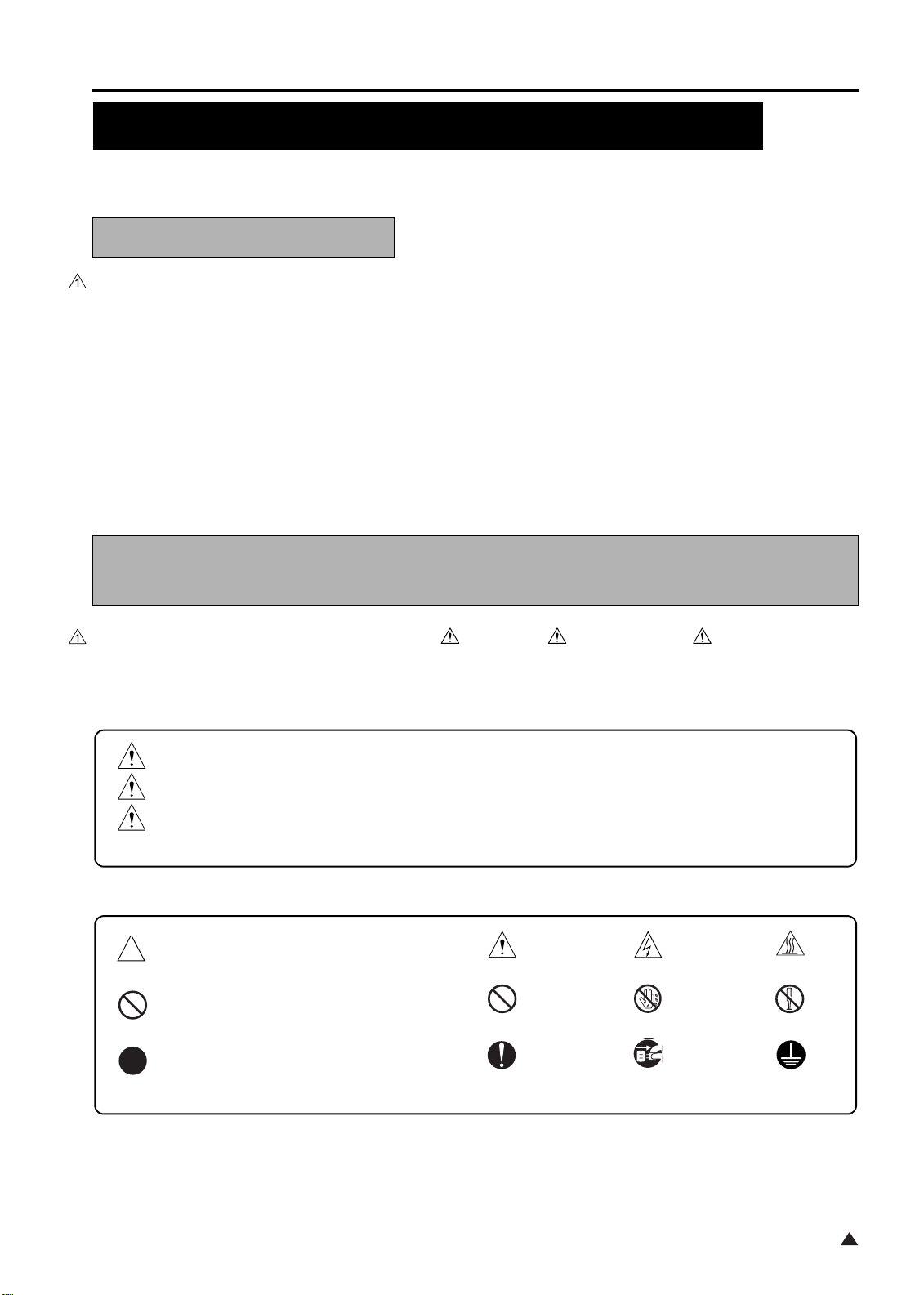
In this Service Manual, each of three expressions “ DANGER”, “ WARNING”, and “ CAUTION” is defined
as follows together with a symbol mark to be used in a limited meaning.
When servicing the copier, the relevant works (disassembling, reassembling, adjustment, repair, maintenance,
etc.) need to be conducted with utmost care.
DANGER
WARNING
CAUTION
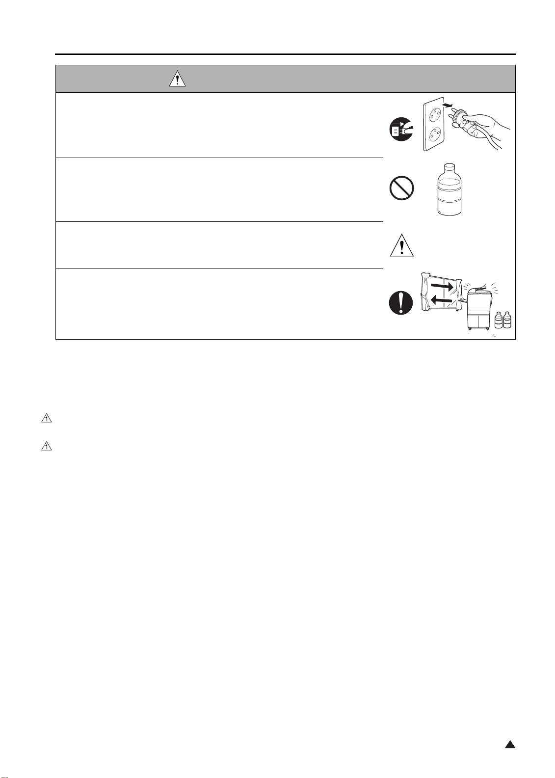
Symbols used for safety and important warning items are defined as follows:
:Precaution when using the copier.
:Prohibition when using the copier.
:Action having a high possibility of suffering death or serious injury
:Action having a possibility of suffering death or serious injury
:Action having a possibility of suffering a slight wound, medium trouble, and
property damage
General precaution Electric hazard High temperature
General prohibition Do not touch with wet hand Do not disassemble
:Direction when using the copier.
General instruction
S-1
Unplug
Ground/Earth
1
Page 10
SAFETY AND IMPORTANT WARNING ITEMS
SAFETY WARNINGS
[1] MODIFICATIONS NOT AUTHORIZED BY
KONICA MINOLTA BUSINESS TECHNOLOGIES, INC.
Konica Minolta brand copiers are renowned for their high reliability. This reliability is achieved through high-qual-
ity design and a solid service network.
Copier design is a highly complicated and delicate process where numerous mechanical, physical, and electrical
aspects have to be taken into consideration, with the aim of arriving at proper tolerances and safety factors. For
this reason, unauthorized modifications involve a high risk of degradation in performance and safety. Such mod-
ifications are therefore strictly prohibited. the points listed below are not exhaustive, but they illustrate the rea-
soning behind this policy.
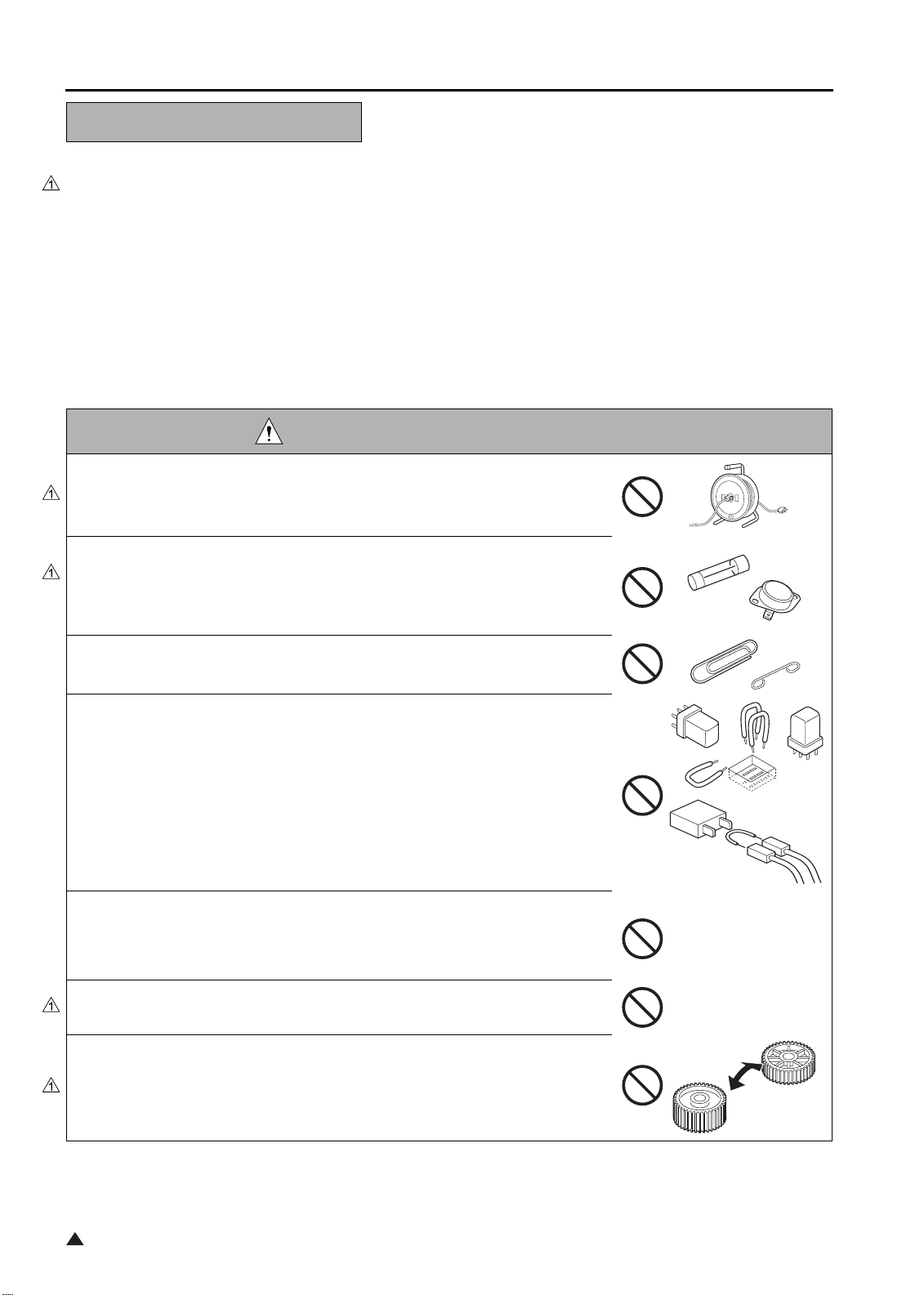
DANGER : PROHIBITED ACTIONS
• Using any cables or power cord not specified by KMBT.
• Using any fuse or thermostat not specified by KMBT. Safety will not be
assured, leading to a risk of fire and injury.
• Disabling fuse functions or bridging fuse terminals with wire, metal clips, sol-
der or similar object.
• Disabling relay functions (such as wedging paper between relay contacts)
• Disabling safety functions (interlocks, safety circuits, etc.) Safety will not be
assured, leading to a risk of fire and injury.
• Making any modification to the copier unless instructed by KMBT
• Using parts not specified by KMBT
1
S-2
Page 11
SAFETY AND IMPORTANT WARNING ITEMS
[2] CHECKPOINTS WHEN PERFORMING ON-SITE SERVICE
Konica Minolta brand copiers are extensively tested before shipping, to ensure that all applicable safety stan-
dards are met, in order to protect the customer and customer engineer (hereafter called the CE) from the risk of
injury. However, in daily use, any electrical equipment may be subject to parts wear and eventual failure. In order
to maintain safety and reliability, the CE must perform regular safety checks.
1.Power Supply
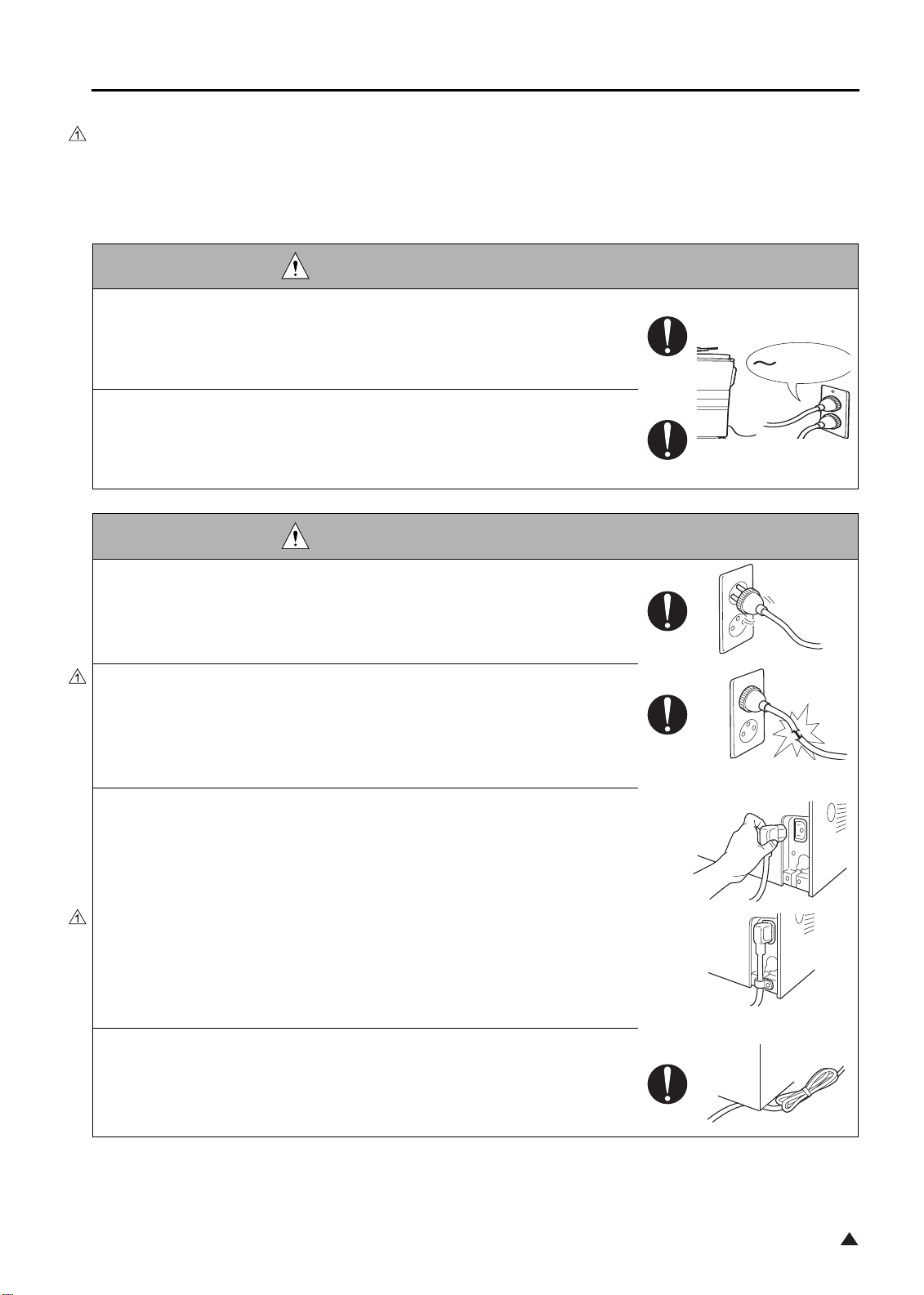
WARNING: Wall Outlet
• Check that mains voltage is as specified. Plug the power cord into the dedi-
cated wall outlet with a capacity greater than the maximum power consump-
tion.
If excessive current flows in the wall outlet, fire may result.
• If two or more power cords can be plugged into the wall outlet, the total load
must not exceed the rating of the wall outlet.
If excessive current flows in the wall outlet, fire may result.
kw
WARNING: Power Plug and Cord
• Make sure the power cord is plugged in the wall outlet securely.
Contact problems may lead to increased resistance, overheating, and the
risk of fire.
• Check whether the power cord is damaged. Check whether the sheath is
damaged.
If the power plug, cord, or sheath is damaged, replace with a new power
cord (with plugs on both ends) specified by KMBT. Using the damaged
power cord may result in fire or electric shock.
• When using the power cord (inlet type) that came with this copier, be sure to
observe the following precautions:
a. Make sure the copier-side power plug is securely inserted in the socket
on the rear panel of the copier.
Secure the cord with a fixture properly.
b. If the power cord or sheath is damaged, replace with a new power cord
(with plugs on both ends) specified by KMBT.
If the power cord (inlet type) is not connected to the copier securely, a
contact problem may lead to increased resistance, overheating, and risk
of fire.
• Check whether the power cord is not stepped on or pinched by a table and
so on.
Overheating may occur there, leading to a risk of fire.
S-3
1
Page 12
SAFETY AND IMPORTANT WARNING ITEMS
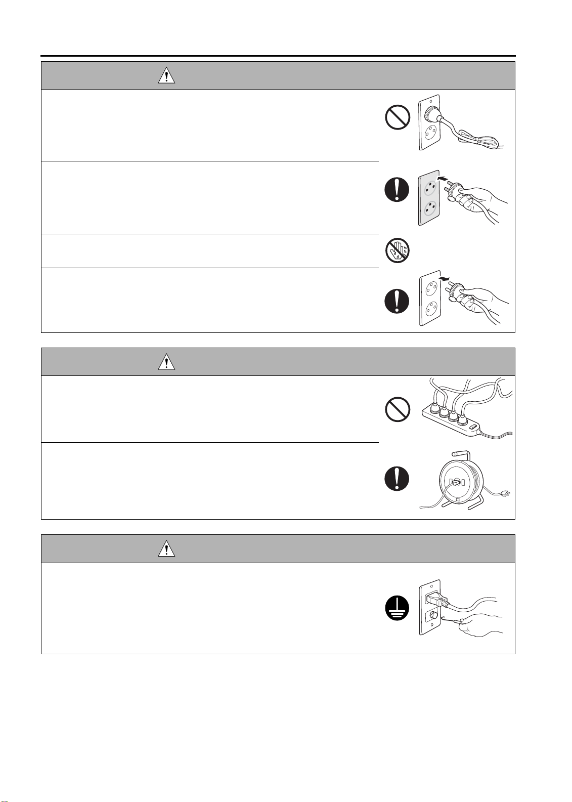
WARNING: Power Plug and Cord
• Do not bundle or tie the power cord.
Overheating may occur there, leading to a risk of fire.
• Check whether dust is collected around the power plug and wall outlet.
Using the power plug and wall outlet without removing dust may result in
fire.
• Do not insert the power plug into the wall outlet with a wet hand.
The risk of electric shock exists.
• When unplugging the power cord, grasp the plug, not the cable.
The cable may be broken, leading to a risk of fire and electric shock.
WARNING: Wiring
• Never use multi-plug adapters to plug multiple power cords in the same out-
let.
If used, the risk of fire exists.
• When an extension cord is required, use a specified one.
Current that can flow in the extension cord is limited, so using a too long
extension cord may result in fire.
Do not use an extension cable reel with the cable taken up. Fire may
result.
WARNING: Ground Lead
• Check whether the copier is grounded properly.
If current leakage occurs in an ungrounded copier, you may suffer electric
shock while operating the copier. Connect the ground lead to one of the
following points:
a. Ground terminal of wall outlet
b. Ground terminal for which Class D work has been done
S-4
Page 13
SAFETY AND IMPORTANT WARNING ITEMS
WARNING: Ground Lead
• Pay attention to the point to which the ground lead is connected.
Connecting the ground lead to an improper point such as the points listed
below results in a risk of explosion and electric shock:
a. Gas pipe (A risk of explosion or fire exists.)
b. Lightning rod (A risk of electric shock or fire exists.)
c. Telephone line ground (A risk of electric shock or fire exists in the case
of lightning.)
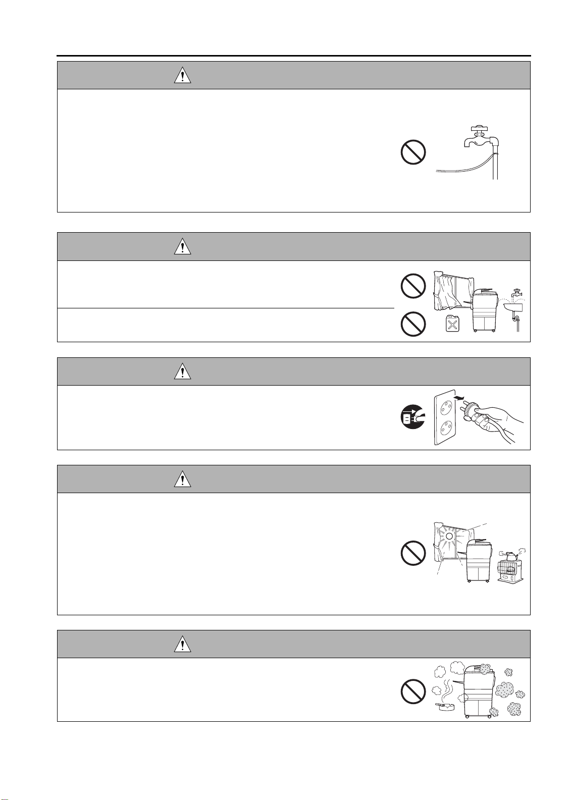
d. Water pipe or faucet (It may include a plastic portion.)
2.Installation Requirements
WARNING: Prohibited Installation Place
• Do not place the copier near flammable materials such as curtains or volatile
materials that may catch fire.
A risk of fire exists.
• Do not place the copier in a place exposed to water such as rain water.
A risk of fire and electric shock exists.
WARNING: Nonoperational Handling
• When the copier is not used over an extended period of time (holidays, etc.),
switch it off and unplug the power cord.
Dust collected around the power plug and outlet may cause fire.
CAUTION: Temperature and Humidity
• Do not place the copier in a place exposed to direct sunlight or near a heat
source such as a heater.
A risk of degradation in copier performance or deformation exists.
Do not place the copier in a place exposed to cool wind.
Recommended temperature and humidity are as follows:
Temperature: 10
Humidity: 10% to 80% (no dew condensation)
Avoid other environments as much as possible.
°
C
to 30
C
°
CAUTION: Ventilation
• Do not place the copier in a place where there is much dust, cigarette
smoke, or ammonia gas.
Place the copier in a well ventilated place to prevent machine problems
and image faults.
S-5
Page 14
SAFETY AND IMPORTANT WARNING ITEMS
CAUTION: Ventilation
• The copier generates ozone gas during operation, but it is not sufficient to be
harmful to the human body.
If a bad smell of ozone is present in the following cases, ventilate the
room.
a. When the copier is used in a poorly ventilated room
b. When taking a lot of copies
c. When using multiple copiers at the same time
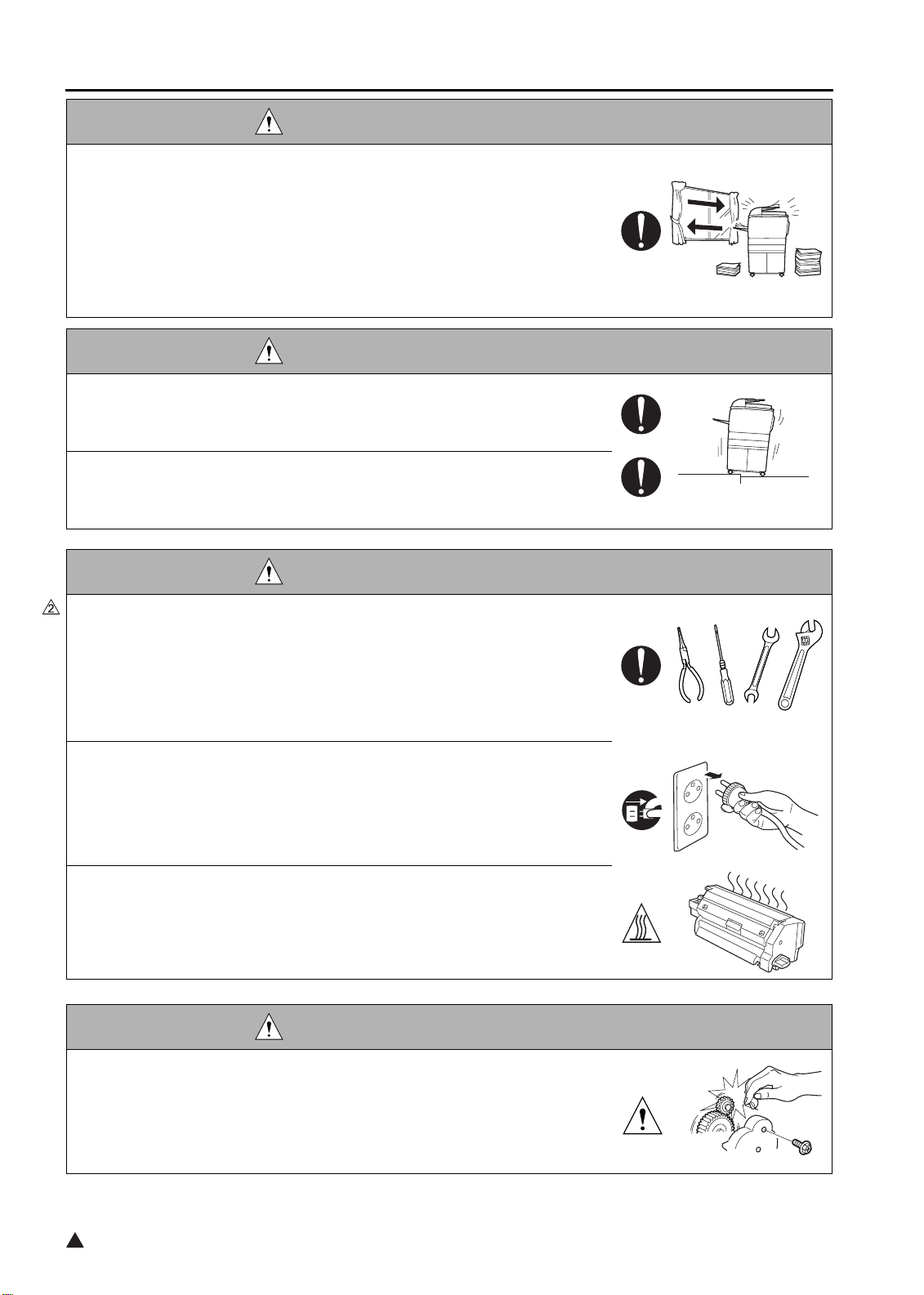
CAUTION: Vibration
• When installing the copier, read the Installation Guide thoroughly. Be sure to
install the copier in a level and sturdy place.
Constant vibration will cause problems.
• Be sure to lock the caster stoppers.
In the case of an earthquake and so on, the copier may slide, leading to a
injury.
CAUTION: Inspection before Servicing
• Before conducting an inspection, read all relevant documentation (service
manual, technical notices, etc.) and proceed with the inspection following the
prescribed procedure in safety clothes, using only the prescribed tools. Do
not make any adjustment not described in the documentation.
If the prescribed procedure or tool is not used, the copier may break and a
risk of injury or fire exists.
• Before conducting an inspection, be sure to disconnect the power plugs from
the copier and options.
When the power plug is inserted in the wall outlet, some units are still pow-
ered even if the POWER switch is turned OFF. A risk of electric shock
exists.
• The area around the fixing unit is hot.
You may get burnt.
DANGER: Work Performed with the Copier Powered
• Take every care when making adjustments or performing an operation check
with the copier powered.
If you make adjustments or perform an operation check with the external
cover detached, you may touch live or high-voltage parts or you may be
caught in moving gears or the timing belt, leading to a risk of injury.
2
S-6
Page 15
SAFETY AND IMPORTANT WARNING ITEMS
DANGER: Work Performed with the Copier Powered
• Take every care when servicing with the external cover detached.
High-voltage exists around the drum unit. A risk of electric shock exists.
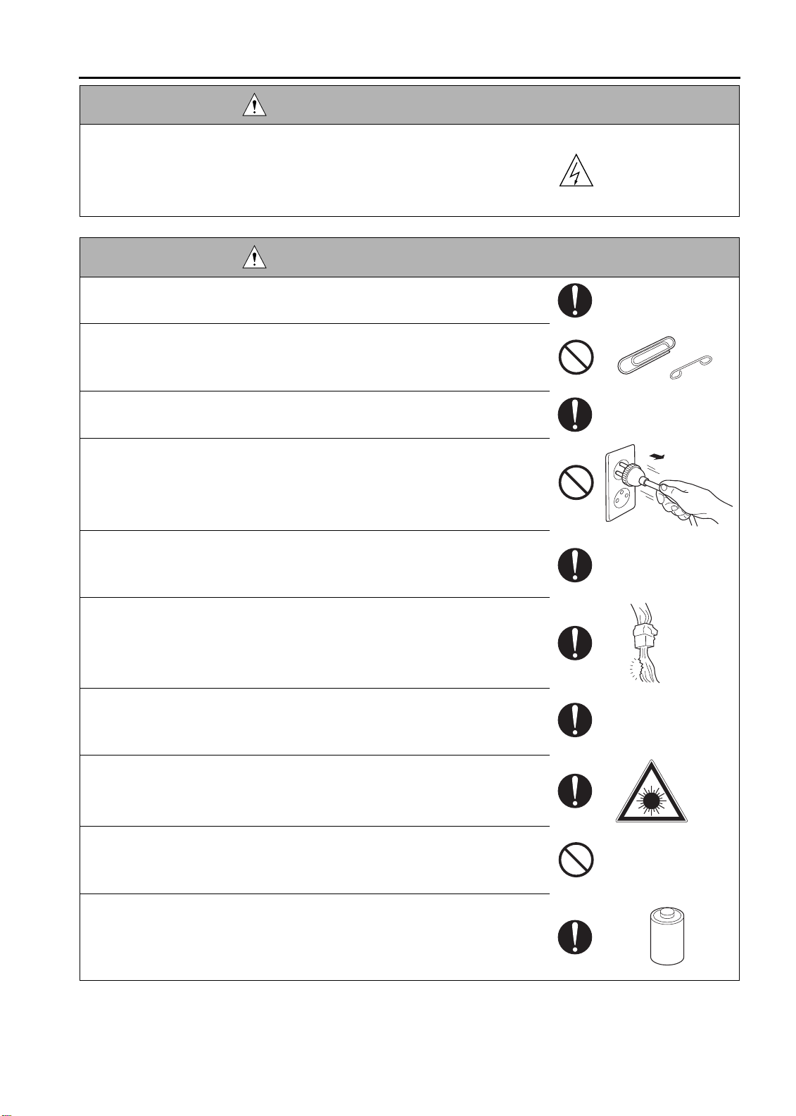
WARNING: Safety Checkpoints
• Check the exterior and frame for edges, burrs, and other damages.
The user or CE may be injured.
• Do not allow any metal parts such as clips, staples, and screws to fall into the
copier.
They can short internal circuits and cause electric shock or fire.
• Check wiring for squeezing and any other damage.
Current can leak, leading to a risk of electric shock or fire.
• When disconnecting connectors, grasp the connector, not the cable.
(Specifically, connectors of the AC line and high-voltage parts)
Current can leak, leading to a risk of electric shock or fire.
• Carefully remove all toner remnants and dust from electrical parts and elec-
trode units such as a charging corona unit.
Current can leak, leading to a risk of copier trouble or fire.
• Check high-voltage cables and sheaths for any damage.
Current can leak, leading to a risk of electric shock or fire.
• Check electrode units such as a charging corona unit for deterioration and
sign of leakage.
Current can leak, leading to a risk of trouble or fire.
• Before disassembling or adjusting the write unit incorporating a laser, make
sure that the power cord has been disconnected.
The laser light can enter your eye, leading to a risk of loss of eyesight.
• Do not remove the cover of the write unit. Do not supply power with the write
unit shifted from the specified mounting position.
The laser light can enter your eye, leading to a risk of loss of eyesight.
• When replacing a lithium battery, replace it with a new lithium battery speci-
fied in the Parts Guide Manual. Dispose of the used lithium battery using the
method specified by local authority.
Improper replacement can cause explosion.
S-7
Page 16
SAFETY AND IMPORTANT WARNING ITEMS
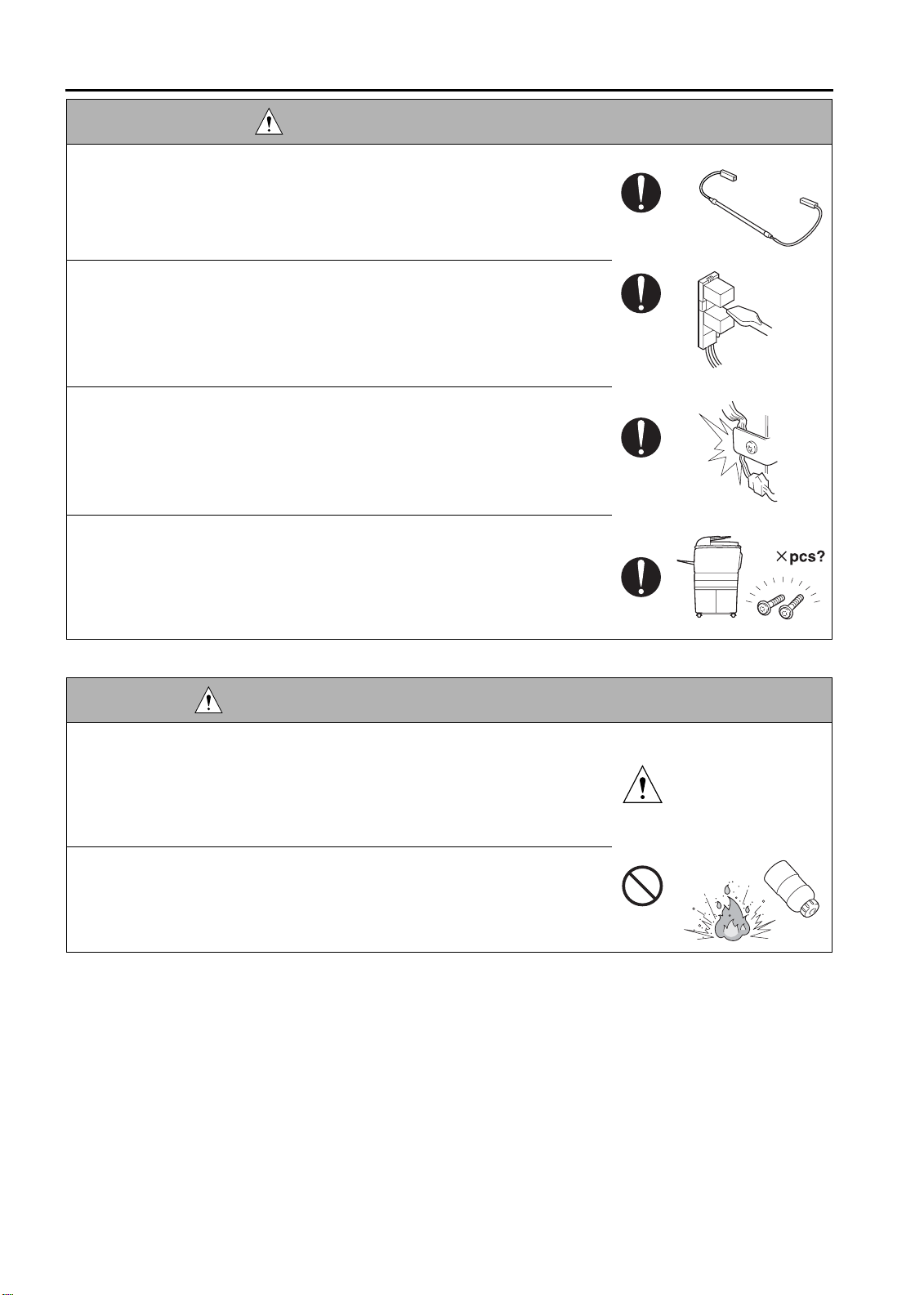
WARNING: Safety Checkpoints
• After replacing a part to which AC voltage is applied (e.g., optical lamp and
fixing lamp), be sure to check the installation state.
A risk of fire exists.
• Check the interlock switch and actuator for loosening and check whether the
interlock functions properly.
If the interlock does not function, you may receive an electric shock or be
injured when you insert your hand in the copier (e.g., for clearing paper
jam).
• Make sure the wiring cannot come into contact with sharp edges, burrs, or
other pointed parts.
Current can leak, leading to a risk of electric shock or fire.
• Make sure that all screws, components, wiring, connectors, etc. that were
removed for safety check and maintenance have been reinstalled in the orig-
inal location. (Pay special attention to forgotten connectors, pinched cables,
forgotten screws, etc.)
A risk of copier trouble, electric shock, and fire exists.
DANGER: HANDLING OF SERVICE MATERIALS
• Toner and developer are not harmful substances, but care must be taken not
to breathe excessive amounts or let the substances come into contact with
eyes, etc. It may be stimulative.
If the substances get in the eye, rinse with plenty of water immediately.
When symptoms are noticeable, consult a physician.
• Never throw the used cartridge and toner into fire.
You may be burned due to dust explosion.
S-8
Page 17
SAFETY AND IMPORTANT WARNING ITEMS
DANGER : HANDLING OF SERVICE MATERIALS
• Unplug the power cord from the wall outlet.
Drum cleaner (isopropyl alcohol) and roller cleaner (acetone-based) are
highly flammable and must be handled with care. A risk of fire exists.
• Do not replace the cover or turn the copier ON before any solvent remnants
on the cleaned parts have fully evaporated.
A risk of fire exists.
• Use only a small amount of cleaner at a time and take care not to spill any
liquid. If this happens, immediately wipe it off.
A risk of fire exists.
• When using any solvent, ventilate the room well.
Breathing large quantities of organic solvents can lead to discomfort.
[3] MEASURES TO TAKE IN CASE OF AN ACCIDENT
1. If an accident has occurred, the distributor who has been notified first must immediately take emergency
measures to provide relief to affected persons and to prevent further damage.
2. If a report of a serious accident has been received from a customer, an on-site evaluation must be carried
out quickly and KMBT must be notified.
3. To determine the cause of the accident, conditions and materials must be recorded through direct on-site
checks, in accordance with instructions issued by KMBT.
4. For reports and measures concerning serious accidents, follow the regulations given in “Serious Accident
Report/Follow-up Procedures”.
[4] CONCLUSION
1. Safety of users and customer engineers depends highly on accurate maintenance and administration.
Therefore, safety can be maintained by the appropriate daily service work conducted by the customer
engineer.
2. When performing service, each copier on the site must be tested for safety. The customer engineer must
verify the safety of parts and ensure appropriate management of the equipment.
S-9
1
Page 18

SAFETY AND IMPORTANT WARNING ITEMS
SAFETY INFORMATION
IMPORTANT INFORMATION
The Center for Devices and Radiological Health (CDRH) of the U.S. Food and Drug Administration implemented
regulations for laser products manufactured since August 1, 1976. Compliance is mandatory for products mar-
keted in the United States.
This copier is certified as a “Class 1” laser product under the U.S.
Department of Health and Human Services (DHHS) Radiation Performance Standard according to the Radiation
Control for Health and Safety Act of 1968. Since radiation emitted inside this copier is completely confined within
protective housings and external covers, the laser beam cannot escape during any phase of normal user opera-
tion.
S-10
Page 19
SAFETY CIRCUITS
SAFETY AND IMPORTANT WARNING ITEMS
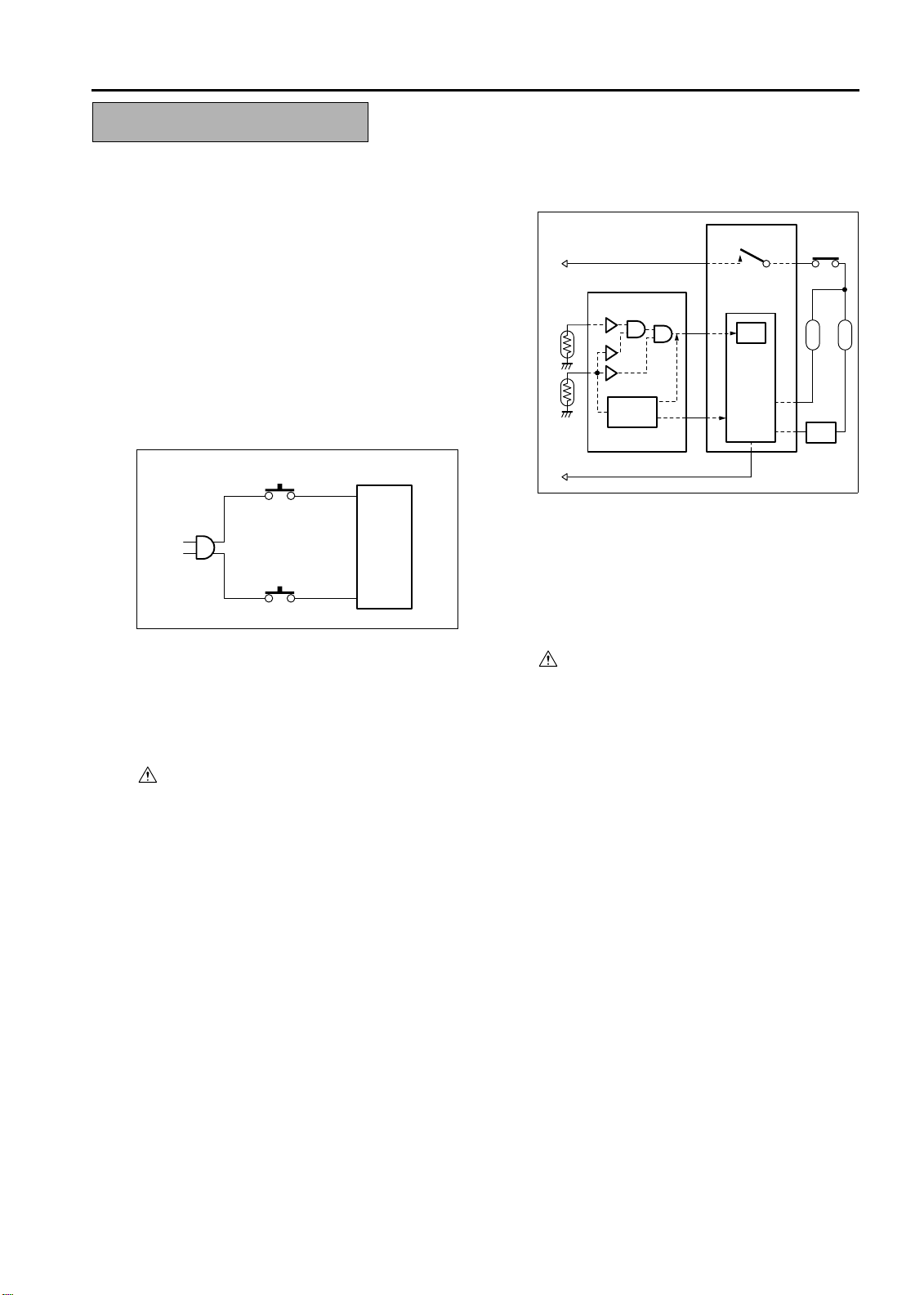
This machine is provided with the following safety circuits
to prevent machine faults from resulting in serious acci-
dents.
[1] Overall protection circuit
[2] L2 and L3 (fixing heater lamp/1, /2) overheat-
ing prevention circuit
These safety circuits are described below to provide
the service engineer with a renewed awareness of
them in order to prevent servicing errors that may
impair their functions.
[1] Overall protection circuit
CBR1
DCPS
CBR2
1. Protection by CBR1 and CBR2 (circuit
breaker/1, /2)
CBR1 and CBR2 interrupt the AC line instanta-
neously when an excessive current flows due
to a short in the AC line.
CAUTION:
The CBR1 and CBR2 functions must not
be deactivated under any circumstances.
[2] L2 and L3 (fixing heater lamp/1, /2)
overheating prevention circuit
DCPS
RL1
CB
RL1
TH1 TH2
Control
section
AC driver
section
1. Protection by software
The output voltage from TH1, TH2 (fixing tem-
perature sensor/1, /2) is read by the CPU. If
this voltage is abnormal, L2 (fixing heater
lamp/1), L3 (fixing heater lamp/2) and RL1
(main relay) are turned OFF.
CAUTION:
The RL1 function must not be deactivated
under any circumstances.
TS
L2
FCB
L3
S-11
Page 20

SAFETY AND IMPORTANT WARNING ITEMS
2. Protection by the hardware circuit
The output voltages from TH1, TH2 (fixing tem-
perature sensor/1, /2) are compared with the
abnormality judgment reference value in the
comparator circuit. If the output voltage from
TH1 or TH2 exceeds the reference value, L2
(fixing heater lamp/1), L3 (fixing heater lamp/2)
and RL1 (main relay) are turned OFF in hard-
ware means.
CAUTION:
Periodically check the TH1, TH2 face
contacting the roller, and replace TH2 if
any abnormality is detected.
The RL1 function must not be deactivated
under any circumstances.
3. Protection by TS (thermostat)
When the fixing heat roller exceeds the speci-
fied value, TSs (thermostats) are turned OFF,
thus interrupting the power to L2 (fixing heater
lamp/1), and L3 (fixing heater lamp/2) directly.
CAUTION:
Do not use any other electrical conductor
in place of TS1 and TS2.
2
S-12
Page 21
SAFETY AND IMPORTANT WARNING ITEMS
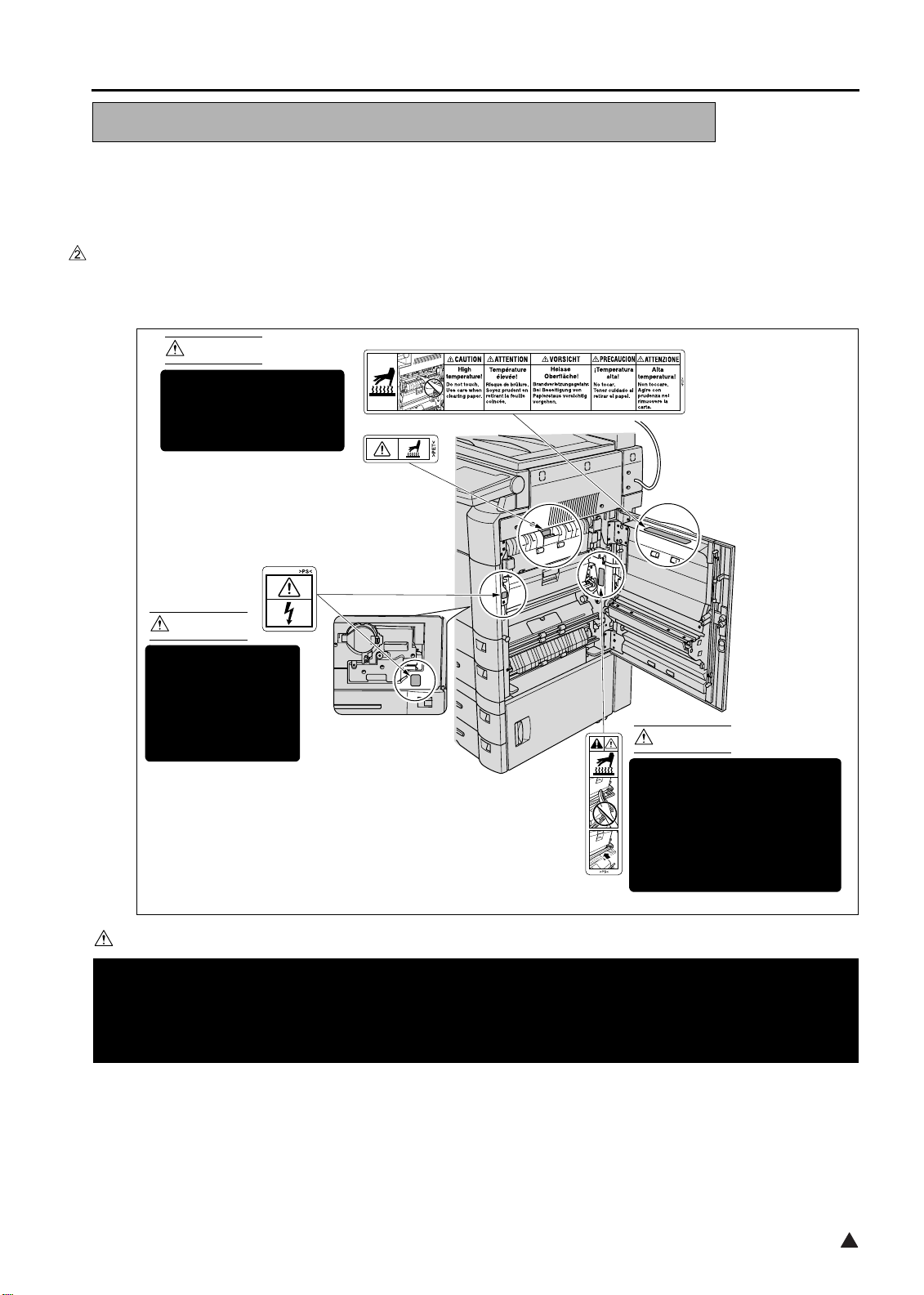
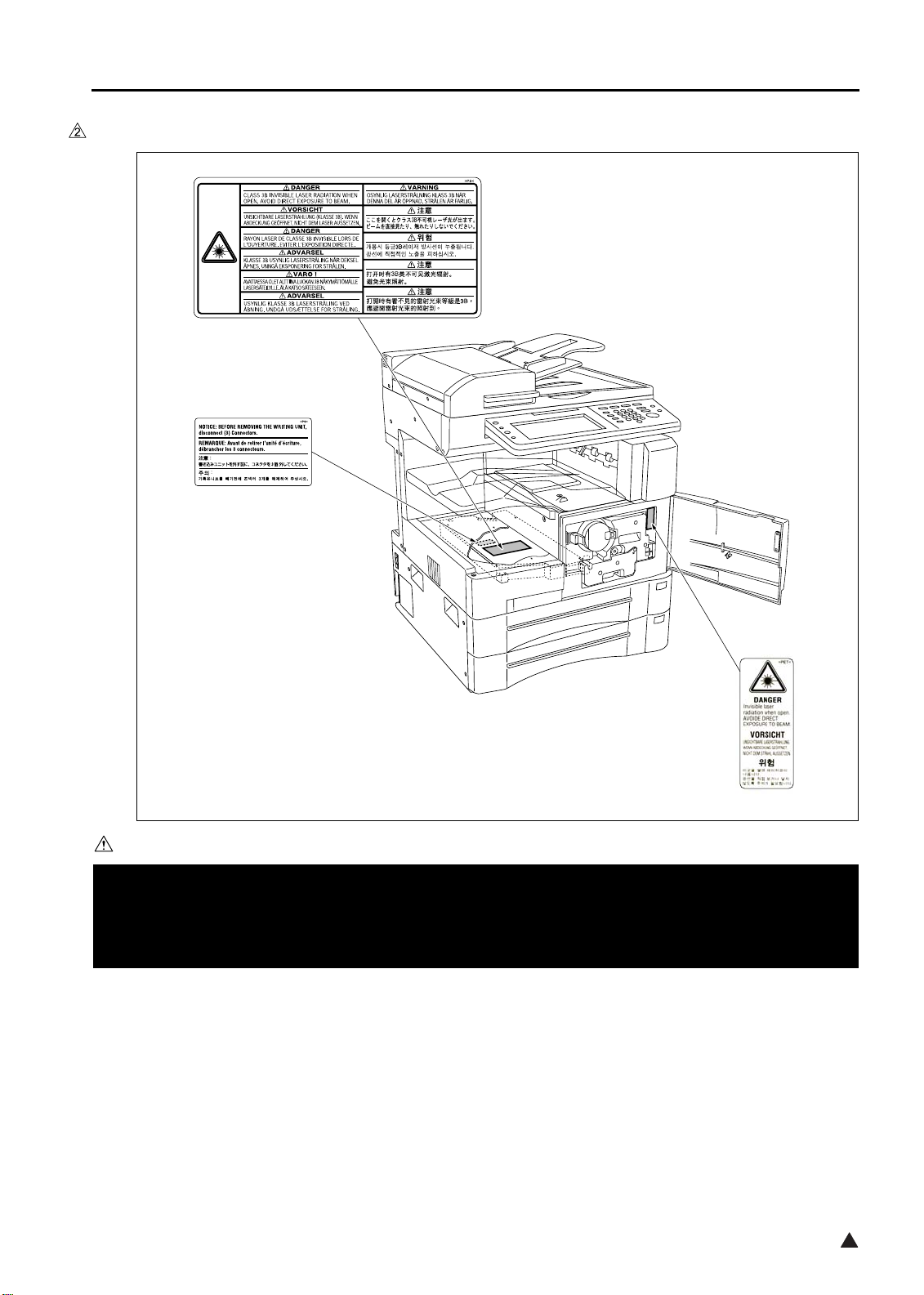
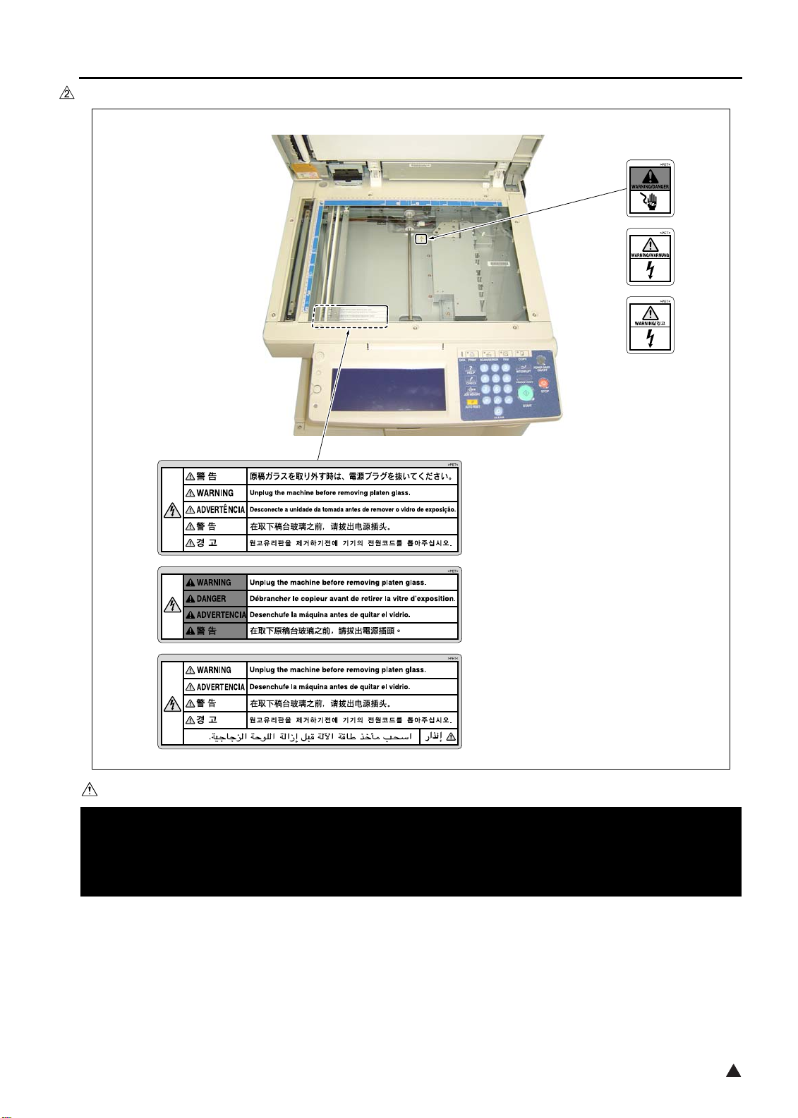
INDICATION OF WARNING ON THE MACHINE
Caution labels shown below are attached in some areas on/in the machine.
When accessing these areas for maintenance, repair, or adjustment, special care should be taken to avoid burns
and electric shock.
[1] Main body
1. Right side
<7145>
CAUTION
The fixing unit is very hot.
To avoid getting burned
DO NOT TOUCH.
CAUTION
This area generates
high voltage.
If touched, electrical
shock may occur.
DO NOT TOUCH!
(Inside of the main
body front door)
CAUTION
The roller shaft on the inside
(Inside of the main
body right side door)
of the cover is very hot.
To avoid getting burned DO
NOT TOUCH.
If the cover comes off, return
it to its original position.
7322sf001e
CAUTION
You may be burned or injured if you touch any area that you are advised by any caution label to keep your-
self away from.
Do not remove caution labels. If any caution label has come off or soiled and therefore the caution cannot
be read, contact our Service Office.
S-13
2
Page 22
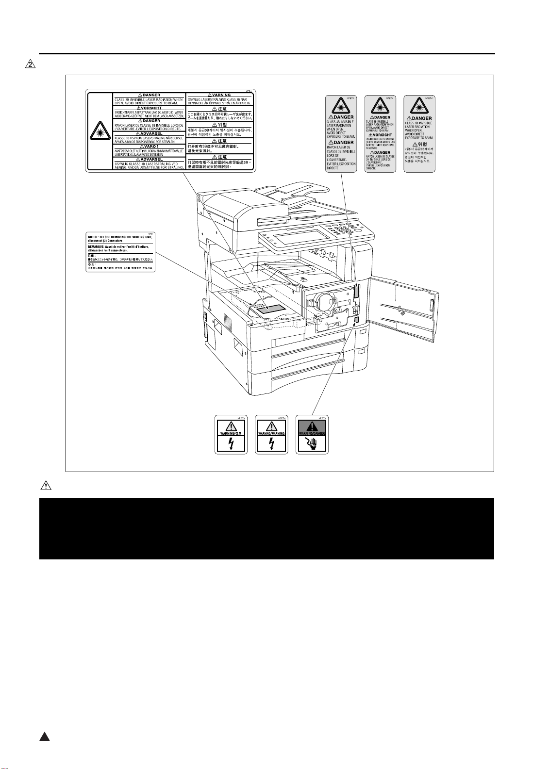
SAFETY AND IMPORTANT WARNING ITEMS
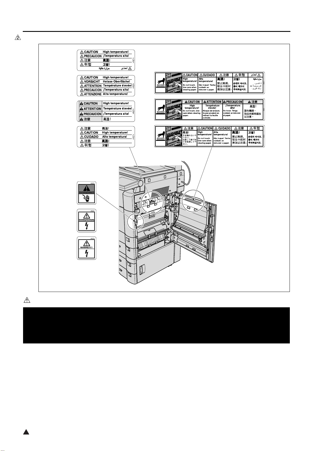
<7235/7228/7222>
7322sf002e
CAUTION
You may be burned or injured if you touch any area that you are advised by any caution label to keep your-
self away from.
Do not remove caution labels. If any caution label has come off or soiled and therefore the caution cannot
be read, contact our Service Office.
2
S-14
Page 23
2. Front side
<7145>
SAFETY AND IMPORTANT WARNING ITEMS
7322sf003e
CAUTION
You may be burned or injured if you touch any area that you are advised by any caution label to keep your-
self away from.
Do not remove caution labels. If any caution label has come off or soiled and therefore the caution cannot
be read, contact our Service Office.
S-15
2
Page 24
SAFETY AND IMPORTANT WARNING ITEMS
<7235/7228/7222>
7322sf004e
CAUTION
You may be burned or injured if you touch any area that you are advised by any caution label to keep your-
self away from.
Do not remove caution labels. If any caution label has come off or soiled and therefore the caution cannot
be read, contact our Service Office.
2
S-16
Page 25
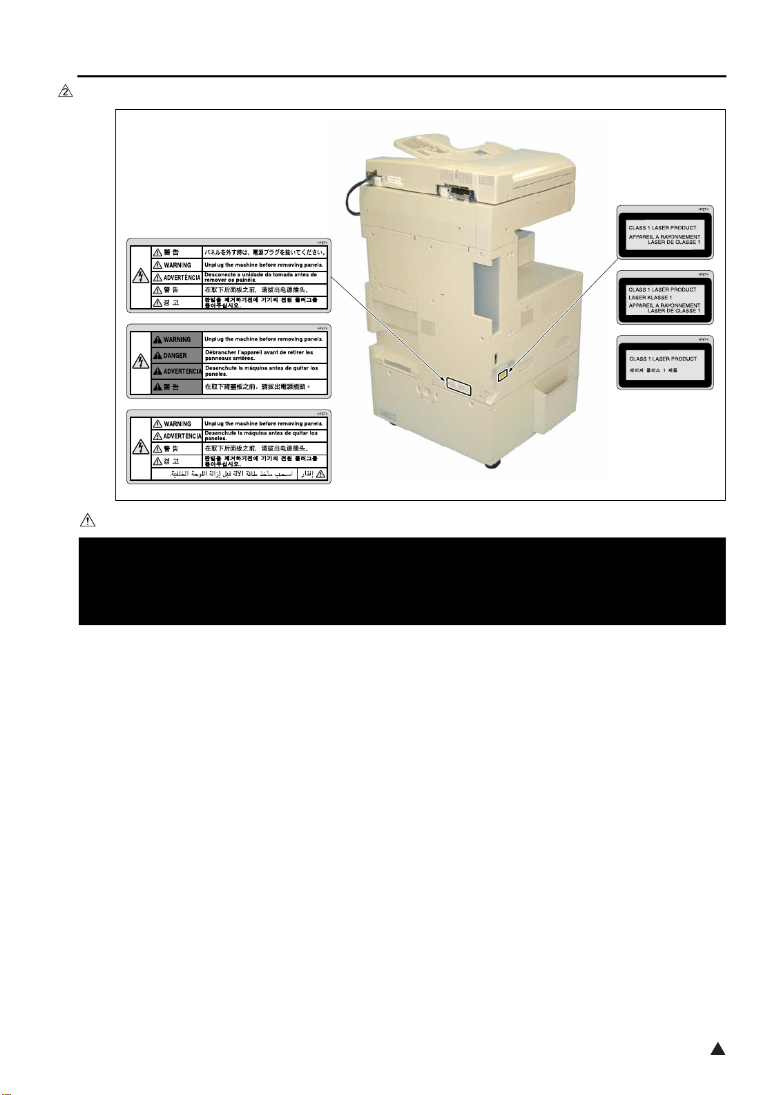
3. Rear/Left side (7235/7228/7222 only)
SAFETY AND IMPORTANT WARNING ITEMS
7322sf005e
CAUTION
You may be burned or injured if you touch any area that you are advised by any caution label to keep your-
self away from.
Do not remove caution labels. If any caution label has come off or soiled and therefore the caution cannot
be read, contact our Service Office.
S-17
2
Page 26
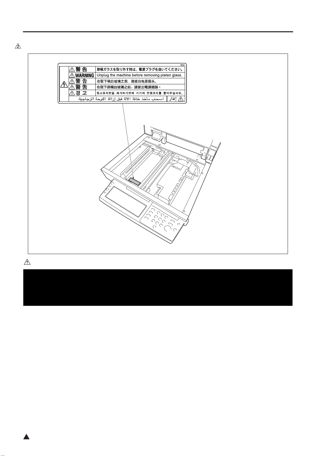
SAFETY AND IMPORTANT WARNING ITEMS
4. Scanner section
<7145>
7322sf006
CAUTION
You may be burned or injured if you touch any area that you are advised by any caution label to keep your-
self away from.
Do not remove caution labels. If any caution label has come off or soiled and therefore the caution cannot
be read, contact our Service Office.
2
S-18
Page 27
<7235/7228/7222>
SAFETY AND IMPORTANT WARNING ITEMS
7322sf007e
CAUTION
You may be burned or injured if you touch any area that you are advised by any caution label to keep your-
self away from.
Do not remove caution labels. If any caution label has come off or soiled and therefore the caution cannot
be read, contact our Service Office.
S-19
2
Page 28
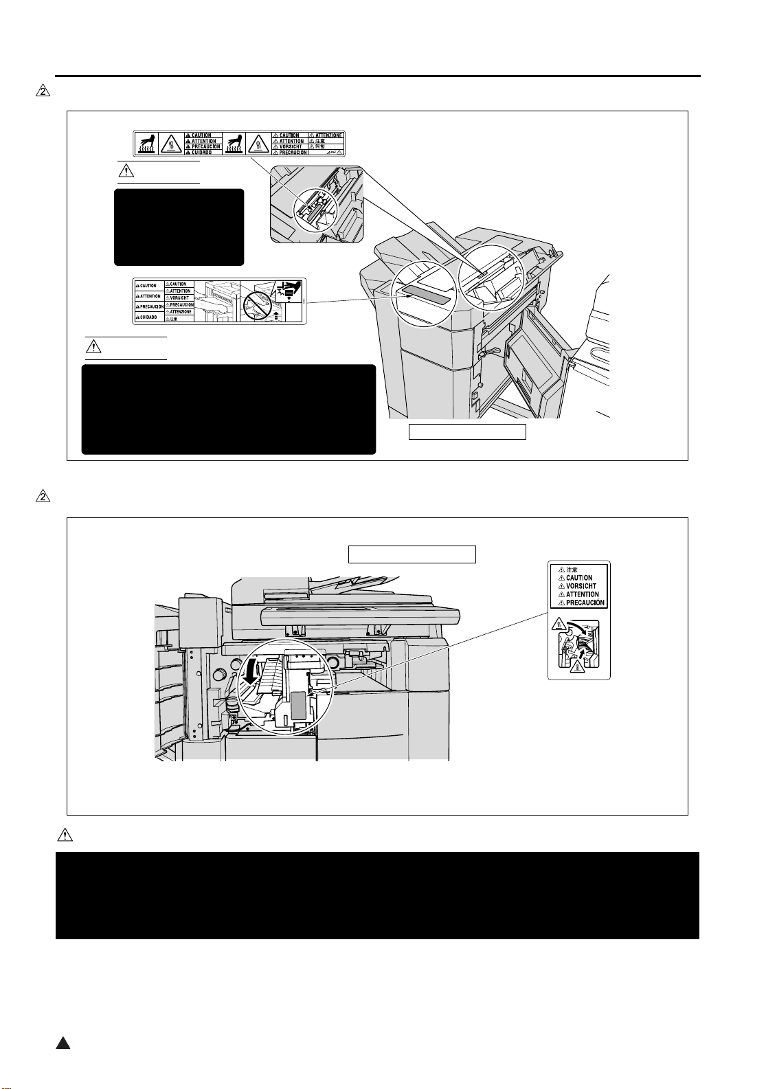
SAFETY AND IMPORTANT WARNING ITEMS
[2] FS-113
CAUTION
This area is very hot.
To avoid getting
burned DO NOT
TOUCH.
CAUTION
To avoid injury, DO NOT put your hand on the top
of the printed sheets. Be sure to hold both sides
of the printed sheets when removing them, and
DO NOT leave your hand on the printed sheets
while the primary (main) tray goes up.
(Inside of the Finisher)
FS-113 Finisher
7322sf009
[3] FS-114
FS-114 Finisher
7322sf010
CAUTION
You may be burned or injured if you touch any area that you are advised by any caution label to keep your-
self away from.
Do not remove caution labels. If any caution label has come off or soiled and therefore the caution cannot
be read, contact our Service Office.
2
S-20
Page 29
List of major differences between the 7145, 7235, 7228 and 7222
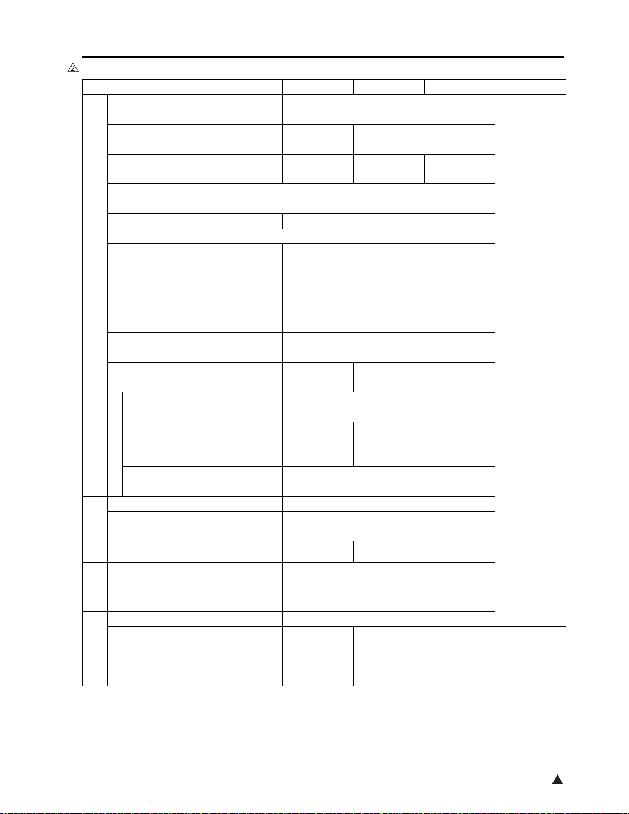
List of major differences between the 7145, 7235, 7228 and 7222
Classification 7145 7235 7228 7222 Reason
Warmup time
First copy out time
(8.5x11)
Continuous copy
speed (8.5x11)
Maximum E-RDH
memory
Less than
30 sec.
Less than
3.8 sec.
Less than
4.3 sec.
Less than 19 sec.
45 sheets/min. 35 sheets/min. 28 sheets/min.
320MB
DF Standard Optional
ADU Standard
Paper exit tray
Optional
Standard
23.2in (W)
Machine dimensions
(with DF and DB)
Specifications
Maintenance
Developer
Toner
Materials
Drum
x
23.4in (D)
x
42.6in (H)
Once every
120,000 copies
Exclusively
for 7145
Exclusively
for 7145
Exclusively
for 7145
23.4in (W) x 25.8in (D) x 44.6in (H)
Once every 100,000 copies
Exclusively for 7235/7228/7222
Exclusively for
7235 (Common
to 7135)
Exclusively for 7228/7222
(Common to 7022/7120/7135)
Exclusively for 7235/7228/7222
Flywheel f 103mm f 132mm
Developing sleeve
drive
Developing
motor
Main motor
Less than 4.9 sec.
22 sheets/min.
Change of
specifications
Vibration insulator Not provided Provided Not provided
Drive section
Scanner drive board Provided Not provided
section
Scanner
Laser 2 beams 1 beam
Number of rotations
of polygon motor
Polygon cooling Not provided Provided Not provided
Write section
27,165rpm 38,976rpm 33,070rpm
1
Change of
CPM
Change of
specifications
2
Page 30
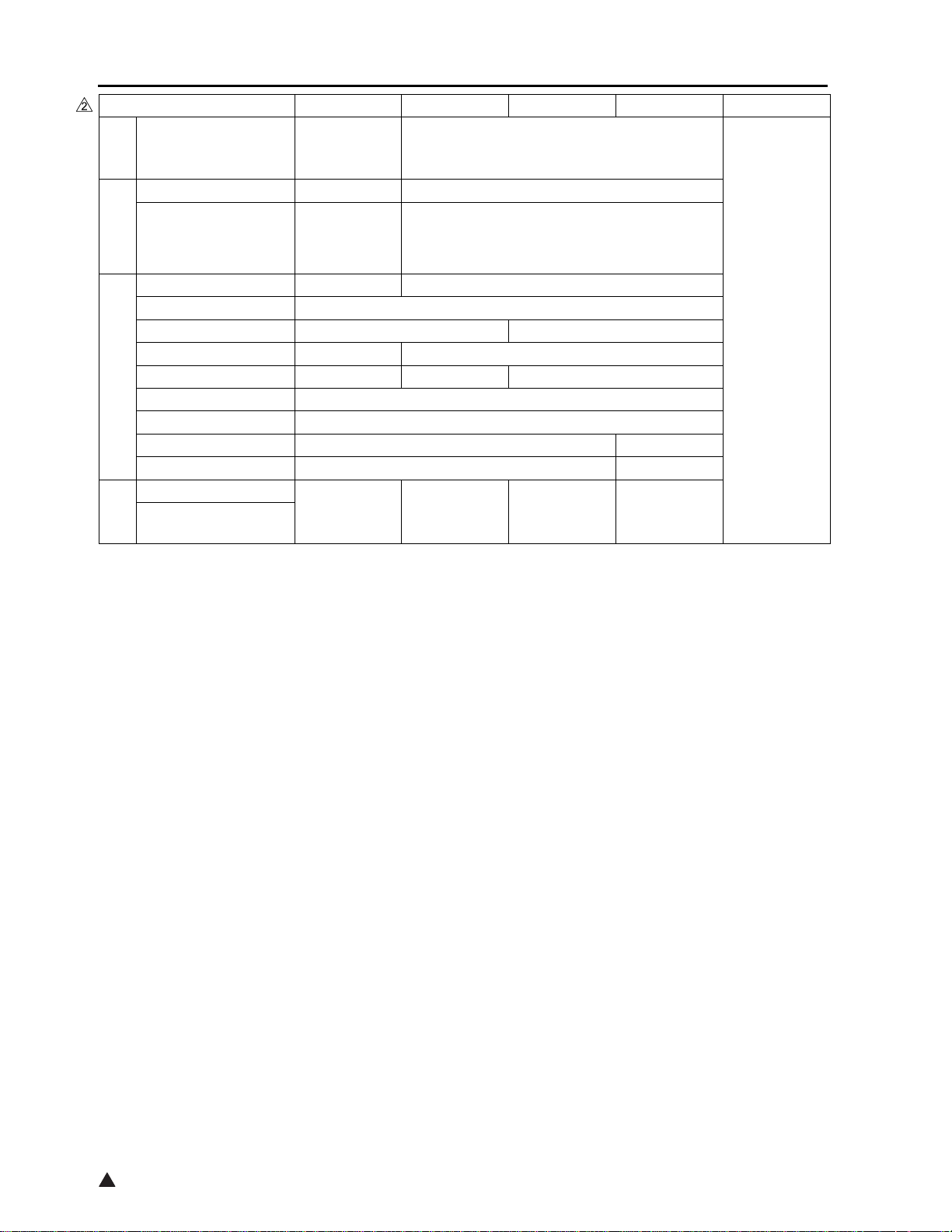
List of major differences between the 7145, 7235, 7228 and 7222
Classification 7145 7235 7228 7222 Reason
Exclusively
for 7145
Exclusively for 7235/7228/7222
Fixing
section
Fixing unit
Decurler roller Provided Not provided
ADU drive board Not provided Provided
ADU/Paper
exit section
Developing motor Provided Not provided
ADU motor Provided
Fixing cooling fan Provided Not provided
Internal cooling fan/2 Provided Not provided
Polygon cooling fan Not provided Provided Not provided
ADU gate solenoid Provided
Electrical parts
ADU sensor Provided
Timing sensor/U Provided Not provided
Timing sensor/L Provided Not provided
Overall control
Image control
Control
Exclusively
for 7145
Exclusively
for 7235
Exclusively
for 7228
Exclusively
Change of
specifications
for 7222
2
2
Page 31

List of options corresponding to the 7145/7235/7228/7222
List of options corresponding to the 7145/7235/7228/7222
Optional 7145 7235 7228 7222
RADF DF-318 Standard Not corresponding
DF-320
Finisher FS-112
FT-107
Not corresponding
Corresponding
Corresponding Not corresponding
FS-113
RU-101
FS-114
BK-114
Corresponding
PK-114
SK-114
Paper exit tray ET-101 Corresponding Corresponding*1
Inner tray IT-101 Corresponding
Desk DK-110
Not corresponding
Corresponding
DB DB-211
CorrespondingDB-411
LCT LT-203
ADU AD-307 Standard
Post script PS-344 Corresponding Not corresponding
PS-346
Printer
controller
FAX controll
board
2 lines
expansion kit
IP-432 Corresponding Not corresponding
IP-424
FK-102 Type-A
FK-103
FL-102 Corresponding Not corresponding
FL-103
Hard disk HD-103 Type-A
Not corresponding
Not corresponding
Corresponding
Corresponding
Corresponding Not corresponding
Not corresponding
Not corresponding
Corresponding
Corresponding
Corresponding
Total counter Standard Corresponding
Key counter Corresponding
*1 A paper exit tray is provided as standard equipment that is different from ET-101. When ET-101 is pro-
vided, it is integrated into the main body as seen from the point of design.
3
2
Page 32

List of options corresponding to the 7145/7235/7228/7222
Blank Page
4
Page 33

IOUTLINE
1. OUTLINE OF SYSTEM
[16]
OUTLINE OF SYSTEM
I OUTLINE
[14] [19][15]
[10]
[13]
[8]
[6]
[12]
[11]
[9]
[7]
[5]
[3]
[4]
[17]
[18][1]
[2]
1-1
7322ma1001
2
Page 34

OUTLINE OF SYSTEM
I OUTLINE
*1 As a standard equipment, the 7235/7228/7222 are provided with a paper exit tray that is different from
[1] Main body [10]
RADF (DF-318: 7145 provided as a standard equipment)
(DF-320: 7235/7228/7222)[2] LCT (LT-203)
[3] LCT DB (DB-411) [11] Paper exit tray (ET-101)*1
[4] 2-Tray DB (DB-211) [12] Finisher (FS-114)
[5] Conveyance unit (RU-101) [13] Additional tray (BK-114)
[6] Finisher (FS-113) [14] Punch kit (PK-114)
[7] Inner tray (IT-101) [15] Crease unit (included in SK-114)
[8] Finisher tray (FT-107: FS-112) [16] Saddle unit (SK-114)
[9] Finisher (FS-112: 7145 only) [17] Desk (DK-110: 7235/7228/7222 only)
[18] ADU (provided as a standard equipment)
[19] Platen cover (CV-109: 7235/7228/7222 only)
the one with which the ET-101 is equipped.
[7]
[5][6]
[1]
[8]
[1] Postscript (PS-344: 7145)
(PS-346: 7235/7228/7222)
Printer controller (IP-432: 7145)
[2]
(IP-424: 7235/7228/7222)
[3]
2 line expansion kit (shipments only to the
United States and
Oceania)
(FL-102:FK-102 Type-A)
(FL-103:FK-103)
[4] Fax control board(FK-102 Type-A: 7145)
(FK-103: 7235/7228/7222)
E-RDH expansion memory (MU-404: 64MB/MU-405: 128MB)
[5]
[2]
[4]
[3]
[6]
Hard disk (HD-103 Type-A)
[7]
Total counter
(7145 provided as standard equipment)
(In the case of the 7235/7228/7222, ship-
ments only to the United States are pro-
vided with the total counter.)
Key counter
[8]
Expansion memory for the printer controller
[9]
(Not displayed here. For details, see the
Service Manual of the controller.)
7145ma1020
2
1-2
Page 35

2. PRODUCT SPECIFICATIONS
A. Type
Type: Semi-console type (7145)
Desk-top type (7235/7228/7222)
Copying method: Indirect electrostatic method
Original table: Fixed
Original alignment: Left rear standard
Photosensitive material: OPC
Sensitizing method: Laser writing
Paper feed trays: Two trays (500 sheets x 2, 80g/m
Multisheet bypass tray (50 sheets, 80g/m
DB-211 (500 sheets x 2, 80g/m2 or 20lbs) *1
DB-411 (1500 sheets, 80g/m
LT-203 (2000 sheets, 80g/m
*1 Optional
B. Functions
2
or 20lbs)
2
or 20lbs) *1
2
or 20lbs) *1
PRODUCT SPECIFICATIONS
2
)
I OUTLINE
Original: Sheet, book, solid object (Thickness: up to 1.2in. Weight: up to 15lbs)
Maximum original size: A3, or 11 x 17
Copy size (for metric area):
Tray 1: B4, A4, A4R, B5, B5R, A5R, 8.5 x 14, 8.5 x 11, 8.5 x 11R, 5.5 x 8.5R, F4
Tray 2: A3, B4, A4, A4R, B5, B5R, A5R, 11 x 17, 8.5 x 11, 8.5 x 11R, F4
Bypass tray: A3, B4, A4, A4R, B5, B5R, A5R, B6R, 8.5 x 11R (7145 only),
8.5 x 11 (except the 7145), F4 (except the 7145)
ADU: A3, B4, A4, A4R, B5, B5R, A5R, 11 x 17, 8.5 x 11, 8.5 x 11R, 8.5 x 14, 5.5
x 8.5R, F4
Copy size (for inch area):
Tray 1: 8.5 x 14, 8.5 x 11, 8.5 x 11R, 5.5 x 8.5R, F4, B4R (7145 only), A4, A4R,
B5, A5R
Tray 2: 11 x 17, 8.5 x 14, 8.5 x 11, 8.5 x 11R, 5.5 x 8.5R, F4, A3, A4, A4R, A5R
Bypass tray: 11 x 17, 8.5 x 14, 8.5 x 11, 8.5 x 11R, 5.5 x 8.5R, A4
ADU: 11 x 17, 8.5 x 14, 8.5 x 11, 8.5 x 11R, 5.5 x 8.5R, A3, B4 (7145 only), A4,
A4R, B5, A5R, F4
Magnification:
Fixed magnification (for metric area):
x 1.00, x 1.41, x 1.22, x 1.15, x 0.86, x 0.82, x 0.71
Fixed magnification (for inch area):
x 1.00, x 2.00, x 1.55, x 1.29, x 0.77, x 0.65, x 0.50
Special ratio: Three kinds
Zoom magnification: x 0.25 to x 4.00 (at 1% step)
Vertical magnification: x 0.25 to x 4.00 (at 1% step)
Horizontal magnification: x 0.25 to x 4.00 (at 1% step)
1-3
2
Page 36

PRODUCT SPECIFICATIONS
Warm-up time: Less than 30 sec. (7145)
(at temperature of 68°F, Less than 19 sec. (7235/7228/7222)
at rated voltage)
First copy out time: Less than 3.8 sec. (7145)
I OUTLINE
Continuous copy speed: 45 copies/min. (7145)
(A4 or 8.5 x 11, 35 copies/min. (7235)
in memory copy) 28 copies/min. (7228)
Continuous copy count: Up to 999
No. of sheets loadable
on the paper exit tray: Up to 100 (8.5x11)
Copy density selection: AE, manual (9 steps), arbitrary density (2 modes)
Resolution:
Scan: 600 dpi x 600 dpi
Write: 600 dpi x 600 dpi
ERDH memory *1: Standard 64MB, Maximum 320MB
Interface section: Serial port (USB TypeB), Serial port (RS-232C), RJ45 Ethernet connector,
Network section: Ethernet frame type: IEEE 802.3/802.3/Ethernet II/
*1 Since the standard 64MB memory is packaged on the board, it is not possible to replace it with a new
one.
Only one slot is provided for expansion. It can be installed with MU-404 (64MB), MU-405 (128MB), or
256MB (commercially available).
For 256MB (commercially available), be sure to use those of make and model No. specified separately.
Less than 4.3 sec. (7235)
Less than 4.9 sec. (7228/7222)
* platen mode, manual density, life size, tray 1, paper exit with face down,
A4 or 8.5 x 11
22 copies/min. (7222)
Parallel port (IEEE1284 (Compatible, Nible, ECP))
IEEE 802.3 SNAP
Connecting type: 10 Base-T/100 Base-TX
Corresponding protocol: TCP/IP (BOOTP, ARP, ICMP, DHCP,
SNMP, HTTP, SMTP, POP3, FTP, IPP),
IPX/SPX, AppleTalk (EtherTalk),
Corresponding OS: Novell NetWare (3.x, 4.x, 5.x), Microsoft
Windows 95/98/Me, Microsoft Windows
NT4.0/2000/XP, Mac OS8.x and later,
Mac OS10.2.5
Multi-protocol: Automatic discrimination
Corresponding printing method: Peer-to-Peer (TCP/IP), LPD/LPR (TCP/
IP), PServer (IPX/SPX), RPrinter (IPX,
SPX), AppleTalk (EtherTalk)
General purpose utility: Web browser (Internet Explorer,
Netscape Navigator)
Status indicator LED: Green LED and orange LED, one for
each
2
1-4
Page 37

PRODUCT SPECIFICATIONS
Number of originals to be stored:More than 140 sheets under the following conditions:
Original: Konica standard chart
Density: Manual 5
Mode: Character/photograph
Memory capacity: 64MB (provided only as standard)
Job: Job in mode with page memory not used
C. Copy Paper
Plain paper: 60g/m2 or 17lbs to 105g/m2 or 28lbs, high-quality paper
Special paper *1 Label paper, OHP film, blueprint-master paper, 50g/m
or 16lbs high-quality paper (thin), 106g/m2 or 28lbs to 130g/m2 or 35lbs
high-quality paper (thick1), 131g/m
quality paper (thick2 *2)
*1 With bypass feed method, paper should be fed one sheet at a time. Double sided copy not allowed.
*2 Only bypass feed.
2
or 35lbs to 160g/m2 or 43lbs high-
2
or 13lbs to 59g/m
D. Machine Data
I OUTLINE
2
Power source: 230VAC –14% to 10.6% 50Hz/60Hz
120VAC –14% to 6% 60Hz
Power consumption: Maximum 1500W or less (fully optional)
Weight: Approximately 183lbs (with DF provided)
Dimensions: 7145: 23.2in (W) x 23.4in (D) x 42.6in (H) (with DF + DB)
7235/7228/7222: 23.4in (W) x 25.8in (D) x 44.6in (H) (with DF + DB)
E. Maintenance
Maintenance: Once every 120,000 copies (7145)
Once every 100,000 copies (7235/7228/7222)
F. Consumables
Developer: Exclusively for 7145
Exclusively for 7235/7228/7222
Toner: Exclusively for 7145
Exclusively for 7235 (Common to 7135)
Exclusively for 7228/7222 (Common to 7022/7120/7130)
Drum: Exclusively for 7145 (φ 60)
Exclusively for 7235/7228/7222 (φ 60)
1-5
2
Page 38

PRODUCT SPECIFICATIONS
G. Operating Environment
Temperature: 10°C to 30°C (50°F to 86°F)
Humidity: 10% RH to 80% RH
I OUTLINE
Note:
• The information herein may be subject to change for improvement without notice.
1-6
Page 39

3. CENTER CROSS SECTION
[18] [19] [20]
CENTER CROSS SECTION
[17]
[16]
[15]
[14]
[13]
[12]
I OUTLINE
[1]
[2]
[3]
[4]
[5]
[6]
[11]
[10]
[1] Fixing unit [10] DB
[2] Drum unit [11] Developing unit
[3] Separation corona unit [12] Tray 2
[4] Transfer corona unit [13] Tray 1
[5] ADU unit [14] Charging corona unit
[6] Bypass tray [15] Cleaning/toner recycling unit
[7] Paper feed path for making a double-sided
copy (DB unprovided)
[8] Paper feed path for making a double-sided
copy (DB provided)
[9] DB paper feed path [20] CCD unit
[16]
[17]
[18]
[19]
Toner bottle
Scanner unit
V-mirror unit
Exposure unit
[7]
[8]
[9]
7322ma1002
1-7
2
Page 40

DRIVE SYSTEM DIAGRAM
4. DRIVE SYSTEM DIAGRAM
4.1 Drum Drive
I OUTLINE
4.2 Cleaning/Developer Agitation Drive
[1]
[2]
[1] M1 (Main motor) [2] Drum drive shaft
[1]
[2]
[3]
[1] M1 (Main motor) [3] Developer agitation drive
[2] Cleaning/toner recycling unit drive
1-8
Page 41

4.3 Fixing/Paper Exit Section/IT-101/RU-101 Drive
DRIVE SYSTEM DIAGRAM
[4]
[3]
[1] IT-101 [4] Paper exit drive
[2] M11 (Fixing motor) [5] Drive coupling for IT-101 and RU-101
[3] Fixing unit drive
[5]
[1]
[2]
I OUTLINE
4.4 Developing Drive
In the case of the 7145
[4]
[1] Developing sleeve [3] M3 (Developing motor)
[2] Developing unit [4] Drum drive shaft
[1]
[2]
[3]
1-9
2
Page 42

DRIVE SYSTEM DIAGRAM
In the case of the 7235/7228/7222
I OUTLINE
[1]
[2]
[3]
[4]
7322ma1003
[1] M1 (Main motor) [3] Developing unit
[2] Developing sleeve [4] Drum drive shaft
4.5 Paper Feed Drive
4.5.1 Drive from paper feed motor to loop clutch
[2]
[1]
[1] MC2 (Loop clutch) [2] M9 (Paper feed motor)
2
1-10
Page 43

4.5.2 Tray 1 drive
DRIVE SYSTEM DIAGRAM
[5][4]
[1]
SD1 (1st paper feed solenoid/U)
[1]
Conveyance roller
[2]
[3] MC2 (Loop clutch) [5] Feed roller
[4] Driven when SD1
(1st paper feed solenoid/U) is on.
I OUTLINE
[2]
[3]
4.5.3 Tray 2 drive
[2]
[5]
[4]
MC2 (Loop clutch)
[1]
Feed roller
[2]
[3] SD2 (1st paper feed solenoid/L) [5] Conveyance roller
[4] Driven when SD2
(1st paper feed solenoid/L) is on.
[1]
[3]
1-11
Page 44

DRIVE SYSTEM DIAGRAM
4.5.4 Bypass feed drive
I OUTLINE
[1] MC2 (Loop clutch) [3] SD3 (Bypass solenoid)
[2] Conveyance roller [4] Driven when SD3 (Bypass solenoid) is on.
[4] [5]
[1]
[3]
[2]
[5] Paper feed roller
4.5.5 Registration clutch drive
[2]
[1]
[1] M9 (Paper feed motor) [2] MC1 (Registration clutch)
1-12
Page 45

4.6 ADU Drive
DRIVE SYSTEM DIAGRAM
[9]
I OUTLINE
[8]
[1]
[7]
[6]
[2]
[5]
[3]
[4]
[1] M1 (Main motor) [5] ADU roller
[2] Timing belt [6] ADU conveyance roller/2
[3] M9 (Paper feed motor) [7] Decurler roller
[4] M6 (ADU motor) [8] ADU conveyance roller/1
[9] M11 (Fixing motor)
1-13
Page 46

DRIVE SYSTEM DIAGRAM
4.7 Scanner Drive
I OUTLINE
[3]
[2]
[1] Optical wire/R [4] Exposure unit
[2] Optical wire/F [5] M2 (Scanner motor)
[3] V-mirror unit
[4]
[5]
[1]
1-14
Page 47

4.8 Toner Supply Drive
[5]
[4]
DRIVE SYSTEM DIAGRAM
I OUTLINE
[2]
[3]
[1] Toner agitation plate [4] M4 (Toner supply motor 1)
[2] Toner conveyance screw [5] M10 (Toner supply motor 2)
[3] SD9 (Toner solenoid)
[1]
1-15
Page 48

DRIVE SYSTEM DIAGRAM
I OUTLINE
Blank page
1-16
Page 49

II UNIT EXPLANATION
1. SCANNER SECTION
1.1 Composition
SCANNER SECTION
7235/7228/7222
[12][11][10][9][8][7]
CB
7145
SCDB
II UNIT EXPLANATION
CB
SCB
[2][3][4][5][6] [1]
Symbol Name Function or method
[1] INV1 (Exposure lamp inverter) L1 (Exposure lamp) turn on
[2] PS17 (APS sensor) Detection of original size in the direction of sub-scanning
[3] ADB (A/D converter board) Digital conversion of analog signal
[4] CCD unit Photoelectric conversion of read image (600dpi)
[5] Exposure unit Image reading
Light source slit exposure
Scan speed
• Forward: 230mm/sec. (in 1:1 magnification)
• Backward: 383mm/sec.
[6] Optical wire Transmission of driving force from M2 to the exposure unit and
the V-mirror unit (front and rear)
[7] V-mirror unit Reflection of reading light (2nd and 3rd mirrors)
[8] PS14 (Scanner HP sensor) Exposure unit HP detection
[9] L1 (Exposure lamp) Light source for reading image,
Xenon lamp
[10] L1INVB (Power supply board
for exposure lamp)
[11] M2 (Scanner motor) Driving of the optical wire used to move the exposure unit and
[12] PS15 (APS timing sensor) RADF open/close detection
Relay board for INV1 (Exposure lamp inverter) and L1 (Expo-
sure lamp)
the V-mirror unit
Three-phase step motor
7322ma2001e
2-1
2
Page 50

SCANNER SECTION
1.2 Operation
1.2.1 Initial operation when power is turned on and shading correction reading
When the SW2 (Sub power switch) comes on, the exposure unit starts a home position search. At this
time, the exposure unit uses the white reference plate attached on the back side of the original pressing
board for shading correction. However, two places on the white reference plate are read for correction.
The search procedure differs depending on whether the PS14 (Scanner HP sensor) is on or off while the
SW2 is on.
A. Home position search when the PS14 is turned on
II UNIT EXPLANATION
[1] Exposure unit standby position [3] Shading correction position 1
[2] PS14 [4] Shading correction position 2
[1][2][3][4]
7322ma2015
B. Home position search when PS14 is turned off
[1][2][3][4]
7322ma2016
[1] Exposure unit standby position [3] Shading correction position 1
[2] PS14 [4] Shading correction position 2
1.2.2 Original reading mode
The following two modes are available for original reading; platen mode and DF mode. In platen mode, the
exposure unit moves as necessary to scan the original for reading. In DF mode, the RADF side moves the
original while the exposure unit stays fixed in a specified position (DF reading position).
2
2-2
Page 51

SCANNER SECTION
A. Exposure unit movement in platen mode
In platen mode, the scan sequence depends on the copy density selection (either AE or manual).
(1) In manual density copy:
[1][6][2][3][4][5]
7322ma2017
Exposure unit standby position
[1]
PS14
[2]
Shading correction position 1
[3]
Shading correction position 2
[4]
[5] Position at which the approach run of the
exposure unit is started
[6] Position at which the reading of an image
is started
Note:
• When the tray 1 is selected manually, but not in APS, the shading operation is not executed.
(2) In AE copy:
[3][4][5][6]
[1][7]
[2]
Exposure unit standby position
[1]
AE scanning range
[2]
PS14
[3]
Shading correction position 1
[4]
[5] Shading correction position 2
[6] Position at which the approach run of the
exposure unit is started
[7] Position at which the reading of an image
is started
II UNIT EXPLANATION
7322ma2018
B. Exposure unit movement in DF mode
[1][2][3][4][5]
[1] Exposure unit standby position [4] Shading correction position 2
[2] PS14 [5] DF reading position
[3] Shading correction position 1
2-3
7322ma2019
2
Page 52

SCANNER SECTION
1.2.3 Original read control
The light from the exposure lamp reflects back from the original, passes through a lens, and hits the CCD
sensor. The CCD sensor generates an electric signal (analog signal) corresponding to the light intensity.
Then, according to the instruction from the SCB (System control board), the ADB (A/D conversion board)
converts this signal into a digital signal.
A. Original read timing
(1) Platen mode, when the manual density is being set
[2] [5]
II UNIT EXPLANATION
M2 (Scanner motor)
PS14 (Scanner HP sensor)
F
R
[1] [3] [4]
[1] START button (ON) [4]
[2] Exposure lamp (forward) [5] Exposure scanning (backward)
[3] Position to which the exposure unit starts
(2) Platen mode, when the AE density is being set
Position at which reading of the original starts
[6] [8][2] [5]
M2 (Scanner motor)
PS14 (Scanner HP sensor)
F
R
[4] [7][1]
[3][3]
START button (ON)
[1]
AE scanning (forward)
[2]
Position to which the exposure unit starts
[3]
Position at which reading of the AE density
[4]
started
2-4
AE scanning (backward)
[5]
Exposure lamp (forward)
[6]
Position at which reading of the original
[7]
starts
Exposure scanning (backward)
[8]
Page 53

B. Original read timing (DF mode) *1
SCANNER SECTION
[4][2]
M2 (Scanner motor)
F
R
PS14 (Scanner HP sensor)
M301
(Original feed motor)
R
250mm/s
230mm/s
F
460mm/s
M302
(Original conveyance motor)
F
230mm/s
460mm/s
[3]
PS308 (Original registration sensor)
[1]
[5] [6]
[1] START button (ON) [4] Exposure conveyance
[2] DF reading position [5]
[3] Position to which the original has been
conveyed in the specified distance.
Position at which reading of the original starts.
[6] Starting point from the DF reading position
to the home position (exposure unit).
*1 In the DF mode, the operation when the manual density setting and the AE density setting is the same.
II UNIT EXPLANATION
1.2.4 APS control
The APS control is carried out at close detection of the RADF, and controlled by the CB (Main body control
board), based on signals from the PS17 (APS sensor) and the CCD sensor. (For APS control by the
RADF, see DF service manual.)
A. APS operation
The PS17 (APS sensor) detects the original size in the sub scanning direction, while the CCD sensor
detects the original size in the main scanning direction.
B. Relationship between each of the sensors and the original size
Original size CCD sensor
(Length of detection: mm)
PS17
(ON/OFF)
A3 297 ON
11 x 17 279.4 ON
B4 257 ON
2-5
2
Page 54

SCANNER SECTION
II UNIT EXPLANATION
Original size CCD sensor
(Length of detection: mm)
8.5 x 14 *1 215.9 ON
8.5 x 11R 215.9 Metric system: ON Inch system: OFF
A4R 210 Metric system: ON Inch system: OFF
A4 297 OFF
8.5 x 11 279.4 OFF
B5R 257 OFF
A5R 210 OFF
B5 182 OFF
A5 148 OFF
5.5 x 8.5 139.7 OFF
B6 128 OFF
Postcard 102 OFF
*1 8.5 x 14 cannot be distinguished from 8.5 x 11R, and is detected as 8.5 x 11R.
(ON/OFF)
PS17
C. APS detection timing
(1) Platen mode (when the RADF is closed)
[1] [2]
PS17 (APS sensor)
PS15 (APS timing sensor)
PS303 (DF open/close sensor)
[1] 1st original size detection [2] 2nd original size detection
(2) Platen mode (when the RADF is open)
[1]
PS17 (APS sensor)
PS15 (APS timing sensor)
PS303 (DF open/close sensor)
[2]
[1] Original size detection [2] START button (ON)
2-6
Page 55

SCANNER SECTION
1.2.5 AE control
During AE scan, the CCD sensor provided on the ADB (A/D conversion board) reads the density level of
the original. The CPU on the SCB (System control board) process the data and, based on the results,
selects the γ correction curve that will best reproduce the original.
A. AE sampling range
(1) While in platen copying
Main scanning direction
• Based on the original size recognized in the APS or out-of-original erasure mode, the range excepting
10mm in front and in rear.
Sub-scanning direction
• The range of 30mm from the leading edge of the original. However, the range excepting L/100mm in
left and right when the length of the original is L mm.
[3]
10 mm
[1]
[2]
10 mm
L
100
30 mm
mm
L
100
L mm
mm
[1] Original [3] AE sampling range
[2] Leading edge of original
II UNIT EXPLANATION
2-7
Page 56

SCANNER SECTION
(2) While in DF copying
Main scanning direction
• Based on the original size recognized in the APS, the range excepting 20mm in front and in rear.
Sub-scanning direction
• The range between 1.5mm and 2.9mm from the leading edge of the original.
[3]
20 mm
[1]
[2]
20 mm
1.5 mm
1.4 mm
II UNIT EXPLANATION
2.9 mm
[1] Original [3] AE sampling range
[2] Leading edge of original
1.2.6 Image processing
A. AOC (Automatic offset control)
The analog offset voltage for the CCD sensor output is automatically adjusted by IC on the ADB (A/D
conversion board) so that this level becomes the lower limit for the A/D converter.
B. AGC (Automatic gain control)
The analog amplification for the CCD sensor output is automatically adjusted so that the CCD sensor
output level in the shading white correction becomes the upper limit for the A/D converter.
C. Shading correction
(1) Types of the shading correction
• White correction
• Black correction
(2) Execution timing
• At SW2 (Sub power switch) ON
• At the start of scan job
D. Other image processing
(1) Brightness/density conversion
(2) Text/dot pattern judgement
(3) Filtering
(4) Magnification change processing
(5) Error diffusion processing
(6) Data compression/elongation processing
2-8
Page 57

2. WRITE UNIT
2.1 Composition
WRITE UNIT
[11][10][9][8][7][6][5]
SCB
CB
7235 only
FM7
[3][4]
Symbol Name Function or method
[1] Index lens Converging of laser beams reflected from the index mirror
[2] INDEX (Index sensor board)
[3] Polygon mirror Laser beam scanning
[4] M5 (Polygon motor) Polygon mirror drive
[5] LDB (LD drive board) Laser emission drive
[6] Collimator lens Making diffused laser beam parallel
[7] Cylindrical lens 1
[8] Index mirror Reflection of laser beam upon the INDEX (Index senror board)
[9] fθ lens
[10] Cylindrical lens 2
[11] Dust-proof glass
FM7*1 Polygon cooling fan
Control of the laser write position in the main scanning direction
Hexahedron, 27,165rpm (7145) /38,976rpm (7235) /
33,071rpm (7228/7222)
DC brushless motor, PLL control
1-chip/2-beam system, 15mW 780mm (7145)
1-chip/1-beam system, 5mW 780mm (Except the 7145)
Correction of the laser path against error in the angle of the polygon mirror
Unified laser scanning speed against the laser irradiation surface on the drum
Correction of the laser path against error in the angle of the polygon mirror
Preventive measure for keeping the interior of the write unit clean
Cooling of the M5 (
Polygon motor
)
[1]
[2]
7322ma2002
II UNIT EXPLANATION
*1 7235 only
2-9
2
Page 58

WRITE UNIT
2.2 Operation
2.2.1 Image writing
The image data from the CCD sensor is converted into digital form by the ADB (A/D conversion board),
and its image processing is then carried out on the SCB (System control board). Based on the processed
image data, the image is written onto the drum by the laser beam output from the LDB (LD drive board).
2.2.2 Write control
A. Dot diameter adjustment
The sensor on the toner control sensor board detects the patch image density on the drum, and the
LDB (LD drive board) controls the quantity of laser beam so that its output value becomes the speci-
fied value.
II UNIT EXPLANATION
(1) Timing for execution
a. While in copying
• Executed once for every 20 copies added up. However, when 20 copies are added up in the middle of
the job, the execution is made at the time of completion of the job.
b. Anytime other than while in copying
• While in the L inspection
• When the drum counter is reset
• When the sub power is turned on. However, this is subject to the settings 6 and 7 of the DIPSW16 in
the 25 mode.
B. APC (Automatic power control)
The LDB (LD drive board) monitors the laser output value for every one scan, and maintains the laser
beam quantity at the fixed level by driving the laser so that it becomes the output value set for the dot
diameter adjustment.
C. Write timing
The SCB (System control board) uses a laser detection signal from the INDEX (Index sensor board) to
determine the starting point for laser writing for every one scan in the drum shaft direction.
2
2-10
Page 59

3. DRUM UNIT
3.1 Composition
[6]
DRUM UNIT
[10][9][8][7]
SD7
M1
CB
II UNIT EXPLANATION
HV
[2][3][4][5]
Symbol Name Function or method
[1] TSL
(Transfer synchronization lamp)
[2] Transfer corona unit Transfer of toner from the drum to paper
[3] Paper entrance guide plate Conveyance guide for paper supplied
[4] Drum Image formation base
[5] Developing unit Formation of a toner image on the drum
[6] Charging corona unit Application of electric charge on the drum surface
Separation support
LED
DC positive corona discharge *1
Wire discharge: Tungsten wire with oxide film (φ 0.06mm)
With manual wire cleaning mechanism provided
Constant current DC output range: 0 to 350 µA
High voltage applied to prevent toner adhesion: -500VDC
(constant voltage)
OPC drum (φ 60mm)
(See “4. Developing unit”.)
DC corona discharge (Scotron)
Wire discharge: Gold-plated skin-pass tungsten wire
(φ 0.06mm)
With manual wire cleaning mechanism provided
Constant current DC output range: -320 to -1000 µA
Grid bias: Charging control plate
Constant current DC output range: -450 to -1090V
[1]
TCSB
2-11
2
Page 60

DRUM UNIT
II UNIT EXPLANATION
Symbol Name Function or method
[7] PCL
(Pre-charging exposure lamp)
Erasure of potential on the drum surface
LED
[8] Cleaning/recycle section Cleaning and collection of toner on the drum
(See “5. Toner supply/cleaning/recycle section”.)
[9] Separation claw Support for the separation of paper from the drum
Pressure/release method by SD7 (Separation claw solenoid)
[10] Separation corona unit Separation of transferred paper from the drum
AC/DC corona discharge *1
Wire discharge: Tungsten wire with oxide film (φ 0.06mm)
With manual wire cleaning mechanism provided
Constant current AC output range: 1.5 to 5.0kV
Constant current DC output range: 0 to -300µA
SD7 Separation claw solenoid Separation claw pressure/release
24VDC drive
M1 Main motor Driving of the drum, cleaning/recycling section
DC brushless motor, PLL control
HV High voltage power High voltage power supply to the charging corona, transfer
corona, separation corona, paper entrance guide plate and
developing bias
Method to increase voltage by inverter from 24VDC
TCSB Toner control sensor board Detection of the patch image density on the drum
Detection of temperature around the drum
*1 Control is made so that an output value becomes a little higher for a thick paper and a little lower for a
thin paper as compared with a plain paper.
Note for the transfer/separation corona
Caution:
• A copy should not be made when the ADU door is open with the interlock forcibly turned on. Oth-
erwise, the contact (spring) of the ADU door develops high voltage and you may get an electric
shock.
2
2-12
Page 61

[4]
DRUM UNIT
[3]
[2]
[1]
[1] ADU door [3] Transfer/separation corona unit
[2] Contact [4] HV (High voltage unit)
3.2 Operation
3.2.1 Image formation timing (when copying two sheets)
A. In the case of the 7145
M1 (Main motor)
M3 (Developing motor)
PS1 (Registration sensor)
MC1 (Registration clutch)
PCL (Pre-charging exposure lamp)
HV (Charging corona)
HV (Developing bias)
HV (Transfer corona)
II UNIT EXPLANATION
HV (Separation corona)
HV (Paper entrance guide plate)
TSL (Transfer synchronization lamp)
DS7 (Separation claw solenoid)
PS2 (Fixing exit sensor)
[2]
[3][1]
7322ma2020
[1] START button (ON) [3] Driving of the separation claw to prevent
[2] Varies depending on the type of paper.
the trailing edge of paper from getting
stained.
2-13
2
Page 62

DRUM UNIT
B. In the case of the 7235/7228/7222
M1 (Main motor)
PS1 (Registration sensor)
MC1 (Registration clutch)
PCL (Pre-charging exposure lamp)
HV (Charging corona)
HV (Developing bias)
HV (Transfer corona)
HV (Separation corona)
HV (Paper entrance guide plate)
II UNIT EXPLANATION
TSL (Transfer synchronization lamp)
DS7 (Separation claw solenoid)
PS2 (Fixing exit sensor)
[1]
[2]
[3]
7322ma2012
[1] START button (ON) [3] Varies depending on the environment in
which it is installed.[2] Varies depending on the type of paper.
2
2-14
Page 63

4. DEVELOPING UNIT
4.1 Composition
DEVELOPING UNIT
7235/7228/7222
M1
[5][4]
CB
7145
M1
M3
HV
[2][3]
Symbol Name Function or method
[1] TDS (Toner density sensor) Detection of toner density in the developing unit
L detection method
[2] Developing sleeve Coveyance of developing materials by magnetic force to the
drum surface
Two-component developing method (developing materials:
Toner + Carrier)
Developing bias voltage applied
Constant voltage DC output range: -350 to -830V
[3] Developing regulation plate Regulation of the spiking amount of developing materials on
the developing sleeve
Regulation plate method
[4] Agitator screw Agitation of developer and conveyance of developing materials
to the agitator wheel
Agitator wheel method
[5] Agitator wheel Agitation of developer and conveyance of developing materials
to the developing sleeve
4-vane wheel method
M1 Main motor Driving of the agitating turbine, the agitating screw and the
developing sleeve (except the 7145)
DC brushless motor, PLL control
M3*1 Developing motor Driving of the developing sleeve
[1]
CB
7322ma2003e
II UNIT EXPLANATION
*1 7145 only
2-15
2
Page 64

DEVELOPING UNIT
4.2 Operation
4.2.1 Developing control
For details of each operation timing of developing, see “3. Drum section”.
4.2.2 Control of toner density in the developing unit
The TDS (Toner density sensor) uses the L detection method (detection of permeability in developing
materials) to detect the toner density of developing materials. The value thus obtained is compared with
the standard value of the toner density for the L detection adjustment that is recorded in the PCU con-
tained in the CB (Main body control board) to see if toner should be supplied or not. (For details of toner
supply, see “5. Toner supply/cleaning/recycling section”.)
II UNIT EXPLANATION
2-16
Page 65

TONER SUPPLY/CLEANING/RECYCLE UNIT
5. TONER SUPPLY/CLEANING/RECYCLE UNIT
5.1 Composition
[7][6] [8][5] [9][4]
M1
M10
CB
SD9
M4
Symbol Name Function or method
[1] Toner collection sheet Collection of toner separated by the cleaning blade from the drum
surface
Rotating collection method
[2] Cleaning blade Drun cleaning
Drum contact/separation method
[3] Toner conveyance screw Agitation of toner and conveyance of toner to the developing unit
Screw method
[4] TLD (Toner level sensor) Detection of the toner level in the toner supply unit (Detected
when the residual quantity of toner gets to about 30g.)
Piezo element method
[5] Toner bottle Toner supply (bottle capacity: 676g)
Toner bottle rotation method
[6] Toner supply paddle Conveyance of toner from the toner bottle to the toner supply unit
Fixed method (Since the toner bottle rotates, this serves as the
toner introduction section.)
[7] Toner agitation plate Agitation of toner supplied from the toner bottle and the cleaning/
recycle section, and conveyance of the toner to the toner convey-
ance screw
Screw method
[8] Collected toner conveyance
screw
Conveyance of toner from the cleaning section to the toner supply
unit
Screw method
[3]
[1]
[2]
II UNIT EXPLANATION
2-17
Page 66

TONER SUPPLY/CLEANING/RECYCLE UNIT
Symbol Name Function or method
[9] PS5 (Toner bottle sensor) Detection of the setting of the toner bottle
M1 Main motor Driving of the toner collection sheet and the collected toner con-
M4 Toner supply motor 1 Driving of the toner conveyance screw and the toner agitator plate
M10 Toner supply motor 2 Toner bottle
SD9 Toner solenoid Transmission of driving force from the M4 (Toner supply motor) to
5.2 Operation
II UNIT EXPLANATION
5.2.1 Toner supply control when the toner level in the toner supply section gets reduced
A. Toner supply operation:
When toner in the toner supply unit is running short, the TLD (Toner level sensor) turns on. This
causes the M10 (Toner supply motor 2) to turn on to rotate the toner bottle and replenish toner to the
toner supply unit. When toner has been supplied, the TLD turns off to monitor the toner level.
Photosensor
veyance screw
DC brushless motor, PLL control
Stepping motor
Stepping motor
the toner conveyance screw
24VDC drive
B. Operation when toner is not supplied:
When the TLD (Toner level sensor) has been kept turned on for the specified period of time, it is con-
sidered that no toner remains in the toner bottle and a message is displayed on the operation LCD.
C. Toner level detection timing:
The TLD (Toner level sensor) detects at all times the toner level during copy operation.
2-18
Page 67

TONER SUPPLY/CLEANING/RECYCLE UNIT
5.2.2 Toner supply control when toner density in the developing unit gets reduced
A. When power is on:
The TDS (Toner density sensor) detects the toner density in the developing unit the specified period of
time after the SW2 (Sub power switch) is turned on. When the value thus detected at this time is
below the initial density recorded in the CPU contained in the CB (Main body control board), the M4
(Toner supply motor 1) and the SD9 (Toner solenoid) are turned on to start to replenish toner up to the
specified level of density.
B. While in copy operation:
While in copy operation, the TDS (Toner density sensor) monitors the toner density. Using the output
voltage of the TDS to turn on the SD9 (Toner solenoid), the M4 (Toner supply motor 1) determines the
time required for toner supply.
TDS output voltage Time required for toner supply
2.01V or less 0 sec.
2.02 to 2.08V 0.10 sec.
2.09 to 2.16V 0.20 sec.
2.17 to 2.23V 0.30 sec.
2.24 to 2.31V 0.40 sec.
2.32 to 2.39V 0.50 sec.
2.40V or more 0.70 sec.
II UNIT EXPLANATION
2-19
Page 68

PAPER FEED UNIT
6. PAPER FEED UNIT
6.1 Composition
[18] [19] [20] [21] [22] [23] [24] [25] [26] [27]
SD1
II UNIT EXPLANATION
[17]
[16]
[15]
[14]
[13]
SD3
SD2
[3][4][5][6][7][8][9][10][11][12]
MC2
M9
PFDB/U
PFDB/L
[1]
[2]
CB
Symbol Name Function or method
[1] VRI (Bypass tray paper size
sensor VR)
[2] PS20
(Bypass tray paper size sensor)
[3] PS13
Detection of paper size in the direction of the width of the by-
pass tray
Detection of paper size in the direction of the length of the by-
pass tray
Detection of the presence of bypass feed paper
(Bypass tray no paper sensor)
[4] Double feed prevention roller Double feed prevention of paper, Torque limiter
[5] Conveyance roller Paper conveyance
[6]*1 PS22 (Timing sensor/L) Detection of tray 2 paper conveyance condition
[7] Double feed prevention roller Double feed prevention of paper, Torque limiter
[8] M8 (Tray motor/L) Tray 2 paper liftup plate drive, DC motor
[9] Feed roller 1st paper feed power transmission
[10] PS12 (Tray set sensor/L) Tray 2 detection and remaining paper detection
[11] PS10 (Upper limit sensor/L) Tray 2 paper upper limit detection
[12] PS11 (No paper sensor/L) Detection of the presence of tray 2 paper
[13] Paper feed roller Tray 2 paper feed
[14] M7 (Tray motor/U) Tray 1 paper liftup plate drive, DC motor
*1 7145/7235/7228 only
2
2-20
Page 69

PAPER FEED UNIT
Symbol Name Function or method
[15] PS9 (Tray set sensor/U) Tray 1 detection and remaining paper detection
[16] PS8 (No paper sensor/U) Detection of the presence of tray 1 paper
[17] PS7 (Upper limit sensor/U) Tray 1 paper upper limit detection
[18] Paper feed roller Tray 1 paper feed
[19] Double feed prevention roller Double feed prevention of paper, Torque limiter
[20] Feed roller 1st paper feed power transmission
[21]*1 PS21 (Timing sensor/U) Detection of tray 1 paper conveyance condition
[22] Conveyance roller Paper conveyance
[23] PS1 (Registration sensor) Detection of the paper passage for the Registration roller rota-
tion ON/OFF
[24] Registration roller Paper conveyance
[25] Conveyance roller Paper conveyance
[26] Feed roller Bypass tray paper feed
[27] Paper feed roller Paper feed
M9 Paper feed motor Paper feed system drive, DC brushless PLL control
MC2 Loop clutch 1st paper feed power transmission
SD1 1st paper feed solenoid/U Tray 1 paper feed power transmission
SD2 1st paper feed solenoid/L Tray 2 paper feed power transmission
SD3 Bypass solenoid Bypass tray paper feed power transmission
PFDB/U
PFDB/L
*1 7145/7235/7228 only
Paper feed detection board/U Tray 1 paper size detection
Paper feed detection board/L Tray 2 paper size detection
CB Main body control board Overall control
II UNIT EXPLANATION
6.2 Operation
6.2.1 Tray up drive control
Since the operation is the same for both the tray 1 and the tray 2, the explanation is given of the tray 1.
When the paper feed tray is set, the PS9 (Tray set sensor/U) detects the tray with the M7 (Tray motor/U)
turned on. This causes the paper up/down plate in the tray to go up. When the PS7 (Upper limit sensor/U)
detects the paper upper limit, the M7 is turned off. When the sheets of paper get reduced as they are being
fed through, the PS7 detects no remaining paper. At this time, the M7 is kept turned on until it detects the
paper upper limit again, and paper is raised up to the specified level at all times.
When the tray is removed, its coupling with the drive section is disconnected to let the paper up/down plate
go down by its own weight.
When papar is supplied by the bypass feed method and the SD3 (Bypass solenoid) turns on after the M9
(Paper feed motor) turns on, the bypass plate goes up to raise paper.
2-21
2
Page 70

PAPER FEED UNIT
6.2.2 Paper feed control
The following shows the timing of paper feed by the tray 1. The timing of paper feed is basically the same
for both the tray 2 and the bypass tray, and the actual paper feed in each case starts when the SD2 (1st
paper feed solenoid/L) or the SD3 (Bypass solenoid) turns on respectively.
[1]
M9 (Paper feed motor)
SD1 (1st paper feed solenoid/U)
PS21 (Timing sensor/U)
MC2 (Loop clutch)
PS1 (Registration sensor)
II UNIT EXPLANATION
[1] START button (ON)
6.2.3 Remaining paper detection control
Since the operation is the same for both the tray 1 and the tray 2, the explanation is given of the tray 1
only.
The remaining paper quantity is detected by the PS9 (Tray set sensor/U). As the remaining paper is get-
ting reduced, the actuator provided on the rear side of the tray starts to ratate gradually as shown in the
drawing. The PS9 turns on and off each time it passes through a slit. The remaining paper quantity is
detected by counting the number of ON/OFF's after the installation of the tray.
0 count: Full 1 count: Medium 2 counts: Low
[1]
[2]
[3]
[4]
[1] Rotating direction when the paper up/down
plate is going up.
[2] PS9 (Tray set sensor/U) [5] Actuator
2-22
[3]
[4]
Slit 1
Slit 2
[5]
Page 71

PAPER FEED UNIT
6.2.4 Paper size detection
The paper size in the tray is detected by the CB (Main body control board), using signals sent from the
PFDB/U (Paper feed detection board/U) and the PFDB/L (Paper feed detection board/L).
The paper size in the tray is set by the SW1 of the PFDB/U and the PFDB/L, and the CB detects a switch
signal according to the position of the SW1. The table below shows the relationship between the switch
signal and the paper size.
For metric area
Paper size Switch signal
Tray 1 Tray 2 SIZE A SIZE B SIZE C SIZE D
8.5 x 14 11 x 17
B5 B5 {
B4 B4 {
A5R A5R {{
A4 A4 {
A4R A4R {{
II UNIT EXPLANATION
F4 A3 {{
5.5 x 8.5R F4 {{{
8.5 x 11 8.5 x 11 {
8.5 x 11R 8.5 x 11R {{
For inch area
Paper size Switch signal
Tray 1 Tray 2 SIZE A SIZE B SIZE C SIZE D
8.5 x 14 11 x 17
B5R A5R {
B4 A4 {
A5R A4R {{
A4 A3 {
A4R F4 {{
F4 5.5 x 8.5R {{
5.5 x 8.5R 8.5 x 11 {{{
8.5 x 11 8.5 x 11R {
8.5 x 11R 8.5 x 14 {{
2-23
Page 72

FIXING UNIT
7. FIXING UNIT
7.1 Composition
[9]
[10]
[13]
[12]
[11]
[1]
[2]
II UNIT EXPLANATION
DCPS
FCB
CB
Symbol Name Function or method
[1] Fixing pressure roller Fixing of toner by pressure
[2] Fixing heat roller Toner fixing by means of heat
M11
SD4
[8] [7] [6]
Silicon rubber + PFA tube
Aluminum + PFA coating
Temperature setting:
Idling: 376 to 369°F
While in copy operation - Other than when feeding paper by the
by-pass tray in the single sided copy mode: 381°F
While in copy operation - When feeding paper by the bypass tray
in the single sided copy mode (by selecting the type of paper)
• Thick paper mode 1: 381 + 50°F
• Thick paper mode 2: 381 + 50°F
• Thin paper: 381 - 50°F (Except the 7145)
• Other than the above: 381°F
Copying - 381 - 41°F, when a double sided copy is being made.
Low power mode: 185°F (can be changed in the 25 mode)
[3]
[4]
[5]
2
2-24
Page 73

FIXING UNIT
Symbol Name Function or method
[3] TH2 (Fixing temperature
sensor/2)
[4] TH1 (Fixing temperature
sensor/1)
[5] Cleaning web Cleaning of the fixing heat roller
[6] Fixing cleaning roller Tension pressure on the cleaning web
[7] TS (Thermostat) Protection of the fixing heat roller against high temperature abnor-
[8] L3 (Fixing heater lamp/2) Heating of the fixing heat roller (Sub)
[9] L2 (Fixing heater lamp/1) Heating of the fixing heat roller (Main)
[10] Fixing guide Paper conveyance guide, pressure/release of the fixing pressure
[11] PS2 (Fixing exit sensor) Detection of paper at the fixing unit exit
[12] Neutralizing brush Neutralizing of paper that is exited
[13] Fixing claw Separation of paper from the fixing heat roller
M11 Fixing motor Driving of the fixing heat roller and the ADU conveyance roller/1
SD4 Cleaning web solenoid Driving of the cleaning web
FCB Fixing control board Prevention of noise leak in the drive power for L3 (Fixing heater lamp
Detection of temperature at the edge (front side) of the fixing heating
roller
Contact type
Detection of temperature at the center of the fixing heating roller
Contact type
Web wind-up method
Spring pressure
mality (about 428°F)
Contact type
AC drive
AC drive
roller
Photosensor + actuator
Neutralizing by means of a brush
Spring pressure type (6 pcs.)
DC brushless motor, PLL control
24V drive
/2)
220V system only
II UNIT EXPLANATION
2-25
Page 74

FIXING UNIT
II UNIT EXPLANATION
7.2 Operation
7.2.1 Fixing temperature control
The CB (Main body control board) uses the TH1 (Fixing temperature sensor/1) and the TH2 (Fixing tem-
perature sensor/2) to detect the temperature of the fixing heating roller, and turns on and off the L2 (Fixing
heater lamp/1) and the L3 (Fixing heater lamp/2) separately through the DCPS (DC power source) to
maintain both the TH1 and the TH2 at the specified temperature.
A. Warm-up
The CB (Main body control board) turns on the fixing heater lamp circuit within the DCPS (DC power
source) immediately after the SW2 turns on, and keeps the L2 (Fixing heater lamp/1) and L3 the (Fix-
ing heater lamp/2) turned on until the fixing heat roller reaches the specified temperature.
Once warm-up has completed, the CB switches the L2 and the L3 on and off so that the fixing heat
roller can be maintained to the set temperature for idling.
• Warm-up time: 30 seconds or less (at the room temperature of 68°F) (7145)
• Warm-up time: 19 seconds or less (at the room temperature of 68°F) (7235/7228/7222)
7.2.2 Cleaning web control
For each output of paper, the cleaning web is let off to be wound up.
The SD4 (Cleaning web solenoid) turns on based on the output of the PS2, causing the cleaning web to be
driven to start a wind-up operation.
PS2 (Fixing exit sensor)
SD4 (Cleaning web solenoid)
[1] [2]
[1] START button (ON) [2] 100 msec
2
2-26
Page 75

8. ADU/PAPER EXIT SECTION
8.1 Composition
ADU/PAPER EXIT SECTION
[9]
[10]
CB
7145
7235/7228/7222
M11
SD5
M9
M6
[1]
[2]
[3]
[4]
II UNIT EXPLANATION
[5]
[6]
CB
Symbol Name Function or method
[1] PS2 (Fixing exit sensor) Detection of paper at the fixing unit exit
[2] ADU unit (ADU door) Paper conveyance while in double sided copy
[3] ADU conveyance roller/1 Paper conveyance through the ADU entrance
[4] Decurler roller (7145)
Conveyance roller (7235/
7228/7222)
[5] ADU conveyance roller/2 Paper conveyance through the ADU intermediate section
[6] Switching sheet Switching of conveyance path at the paper reverse section
ADUDB
M6
[8]
Photosensor + actuator
Jam removal while in double sided copy
Motor drive
Paper conveyance through the ADU intermediate section and the cor-
rection of paper curling (7145)
Paper conveyance through the ADU intermediate section (7235/7228/
7222)
Motor drive
Motor drive
Switching by means of the elasticity of the PET sheet
[7]
7322ma2004e
2-27
2
Page 76

ADU/PAPER EXIT SECTION
Symbol Name Function or method
[7] ADU roller
[8] PS4 (ADU sensor) Detection of paper at the ADU exit
[9] Paper exit roller Paper exit
[10] Switching guide Switching of the paper exit path at the fixing unit exit
ADUDB*1ADU drive board Driving of the M6 (ADU motor)
M6 ADU motor Driving of the ADU motor
M9 Paper feed motor Driving of the decurler roller (7145 only) and the ADU conveyance
II UNIT EXPLANATION
SD5 ADU gate solenoid Pressure and release of the switching guide
M11 Fixing motor Driving of the paper exit roller
*1 Except the 7145
Paper conveyance through the ADU exit and switching of the conveyance direction
Motor drive
Photosensor + actuator
Motor drive
Solenoid drive
Stepping motor
rollers/2
DC brushless motor, PLL control
24VDC drive
DC brushless motor, PLL control
2
2-28
Page 77

ADU/PAPER EXIT SECTION
8.2 Operation
8.2.1 Switching control of the paper exit/ADU conveyance path
A. Straight paper exit path
The straight paper exit path is applicable when a single side is copied as well as after the back side
copy of paper is completed in the double sided copy mode.
[8]
[1]
[7]
[2]
II UNIT EXPLANATION
[3]
[4][5][6]
[1] Switching guide (SD5 OFF) [5] Fixing pressure roller
[2] PS2 (Fixing exit sensor) [6] Fixing heat roller
[3] ADU conveyance driven roller/1 [7] Paper exit driven roller
[4] ADU conveyance roller/1 [8] Paper exit drive roller
2-29
Page 78

ADU/PAPER EXIT SECTION
B. ADU conveyance path
The ADU conveyance path is applicable after the front side copy is completed in the double sided
copy mode.
II UNIT EXPLANATION
[8]
[7]
[1]
[6]
[2]
[3][4][5]
[1] PS2 (Fixing exit sensor) [5] Fixing heat roller
[2] ADU conveyance driven roller/1 [6] Switching guide (SD5 ON)
[3] ADU conveyance roller/1 [7] Paper exit driven roller
[4] Fixing pressure roller [8] Paper exit drive roller
C. Straight paper exit operation (single sided 3 copies)
PS2 (Fixing exit sensor)
SD5 (ADU gate solenoid)
M1 (Main motor)
M11 (Fixing motor)
[1]
[1] 1st paper exit
2-30
Page 79

D. ADU conveyance operation (double sided 3 copies)
MC2 (Loop clutch)
PS2 (Fixing exit sensor)
SD5 (ADU gate solenoid)
M1 (Main motor)
M11 (Fixing motor)
ADU/PAPER EXIT SECTION
[2][1]
7322ma2005
[1] 1st paper exit for the front side [2] 1st paper exit for the back side
8.2.2 ADU conveyance control
When a sheet of paper, the front of which has been printed in the double sided mode is conveyed to the
ADU unit, it is further conveyed to the ADU roller by the decurler roller (7145) or conveyance roller (except
the 7145) and the ADU conveyance rollers/2 which are in turn driven by the M9 (Paper feed motor).
II UNIT EXPLANATION
2-31
2
Page 80

ADU/PAPER EXIT SECTION
8.2.3 Paper reverse control
A. Paper reverse path
(1) When conveying paper
When a sheet of paper is conveyed from the ADU conveyance roller/2, it is further conveyed to the
ADU roller by pushing the switching sheet open.
[9]
[1]
[8]
[7]
II UNIT EXPLANATION
[6]
[2]
[3]
[5]
[4]
[1] ADU conveyance driven roller/2 [6] ADU roller
[2] ADU driven roller [7] Switching sheet
[3] Conveyance path when DB is provided [8] PS4 (ADU sensor)
[4] DB [9] ADU conveyance roller/2
[5] Conveyance path when DB is not provided
7322ma2006
2
2-32
Page 81

ADU/PAPER EXIT SECTION
(2) When paper reverse
Paper that has been conveyed is sent back by means of the reverse rotation of the ADU roller. At this
time, the switching sheet uses its own elastic power to block the conveyance path to the ADU convey-
ance roller/2, and the paper is conveyed to the loop roller of the tray 2. As a result, the paper is turned
inside out to be copied on the back side after passing through the same route as that for the paper
sent from the tray 2.
[7]
[1]
[2]
[3]
[4]
[6]
[5]
II UNIT EXPLANATION
7322ma2007
[1] Loop roller [5] DB
[2] PS4 (ADU sensor) [6] ADU roller
[3] Switching sheet [7] ADU conveyance roller/2
[4] ADU driven roller
B. Paper reverse operation (7145)
PS4 (ADU sensor)
M6 (ADU motor) F
600mm/s
230mm/s
R
230mm/s
M9 (Paper feed motor)
[1] [2] [3] [4] [5] [6]
[1] Start of 1st paper conveyance [4] Start of reverse operation of 2nd paper
[2] Start of revere operation of 1st paper [5] Start of 3rd paper conveyance
[3] Start of 2nd paper conveyance [6] Start of reverse operation of 3rd paper
2-33
2
Page 82

ADU/PAPER EXIT SECTION
C. Paper reverse operation (7235/7228/7222)
PS4 (ADU sensor)
II UNIT EXPLANATION
M6 (ADU motor) F
600mm/s
*1
*1
R
M9 (Paper feed motor)
[1] [2] [3] [4] [5] [6]
7322ma2013
*1 165mm/s (7235) 140mm/s (7228/7222)
[1] Start of 1st paper conveyance [4] Start of reverse operation of 2nd paper
[2] Start of revere operation of 1st paper [5] Start of 3rd paper conveyance
[3] Start of 2nd paper conveyance [6] Start of reverse operation of 3rd paper
2
2-34
Page 83

9. INTERFACE SECTION
9.1 Composition
In the case of the 7145
INTERFACE SECTION
[1]
[2]
[3]
[4]
In the case of the 7235/7228/7222
[2]
[4]
[3]
[1]
Symbol Name Function or method
[1] Serial port (USB TypeB) For ISW of copier/FAX, For serial output of the printer
Ver. 1.1
[2] Serial port (RS-232C) For KRDS communication
D-SUB 9-pin connector
[3] RJ45 Ethernet port Port for network
[4] Parallel port
(IEEE1284 (Compatible,
Nible, ECP))
For ISW of copier/FAX/printer
For parallel output of the printer
36-pin parallel interface
II UNIT EXPLANATION
7322ma2008
2-35
2
Page 84

NETWORK SECTION
10.NETWORK SECTION
10.1 Composition
Item Function name Function Purpose Remarks
TCP/IP service Arp { Obtain IP address
II UNIT EXPLANATION
Netware service Bindery { Print
AppleTalk service
MS Network service
BootP { Obtain IP address
DHCP { Obtain IP address
DNS { Settle IP address
FTP Client { Scan to FTP
FTP Serve r { Scan to Box
IPP { Print Support Ver. 1.0
LPD/LPR { Print
Raw Socket { Print
SMTP { Scan to Email
POP { For POP before SMTP
POP before SMTP { Authorization of SMTP
server access
HTTP 1.1 { WebUtility
SNMP v1
(SNMP over TCP)
SNMP v1
(
SNMP over IPX
Telnet X
SLP X
NDS (including simul-
taneous support of
Bindery)
• PServer mode {
RPrinter/NPrinter mode
•
NDPS
PCONSOLE /NWAD-
MIN, interchangeable
Frame Type (802.3, 8-
02.3, 802.3 SNAP,
Ethernet II)
EtherTalk PAP { Print
SMB over NetBEUI X Print
(
Gateway
)
)
{ MIB access
{ MIB access
{ Print
{
{ Print Corresponding in general
{
{ MAC frame corre-
sponding
Default port number = 9100
purpose Gateway
2-36
Page 85

11. OTHER CONTROLS
11.1 Parts Energized When the Main Power Switch is OFF
SW1
CBR1
AC(H)
OTHER CONTROLS
NF
CBR2
AC(N)
DCPS
The follwing components are powered regardless of whether the SW1 (Main power switch) is on or off,
provided that the power cord remains plugged in.
A. CBR 1 and CBR 2 (Circuit breakers/1 and /2)
The circuit breakers serve to protect internal components against damage from short circuit. If current
exceeds the specified value, the circuit breaker(s) will go off, cutting the power to the system.
B. NF (Noise filter)
This filter reduces noises that enter through the power line.
C. DCPS (DC power source)
This supplies power to each unit, and also controls the ON/OFF state of the fixing heater lamp.
II UNIT EXPLANATION
2-37
Page 86

OTHER CONTROLS
11.2 Components Operated When the Power Switch is ON
11.2.1 Components operated when the SW1 (Main power switch) is on
In the case of the 7145
II UNIT EXPLANATION
SW2
PSW2B
7322ma2009
SW1
DCPS
+12VDC
-12VDC
+5VDC
+24VDC
SCB
PTC
(OPTION)
+12VDC
-12VDC
+5VDC
+12VDC
-12VDC
+5VDC
+12VDC
-12VDC
+5VDC
SGND
+5VDC
SUB_SW
OB
FK-102/FL-102
(OPTION)
IP-432
(OPTION)
Setting the SW1 (Main power switch) to the ON position supplies AC power to the DCPS (DC power
source) which in turn supplies +12DVC, -12VDC, and +5DVC to the SCB (System control board). The
DCPS also supplies +5DVC to the OB (Operation board) through the SCB.
When the PTC (Internal heater) is provided as an option for service parts, according to the setting of the
25 mode DIP SW16-2, +24VDC is supplied to the PTC (Heater) from the DCPS (DC power source).
If options such as a printer controller (IP-432) and/or fax control board (FK-102 Type A/FL-102) are
installed, +12VDC, -12VDC and +5VDC are also supplied to these options through the SCB (System con-
trol board).
In the automatic start-up mode, the same operation is made consecutively as when the SW2 (Sub power
switch) is turned on according to the discretion of the SCB (System control board).
2
2-38
Page 87

In the case of the 7235/7228/7222
OTHER CONTROLS
SW2
PSW2B
7322ma2021
SW1
DCPS
+12VDC
+5VDC
+24VDC
SCB
PTC
(OPTION)
+12VDC
+5VDC
+12VDC
+5VDC
+12VDC
+5VDC
SGND
+5VDC
SUB_SW
OB
FK-103/FL-103
(OPTION)
IP-424
(OPTION)
Setting the SW1 (Main power switch) to the ON position supplies AC power to the DCPS (DC power
source) which in turn supplies +12DVC and +5DVC to the SCB (System control board). The DCPS also
supplies +5DVC to the OB (Operation board) through the SCB.
When the PTC (Internal heater) is provided as an option for service parts, according to the setting of the
25 mode DIP SW16-2, +24VDC is supplied to the PTC (Heater) from the DCPS (DC power source).
If options such as a printer controller (IP-424) and/or fax control board (FK-103/FL-103) are installed,
+12VDC and +5VDC are also supplied to these options through the SCB (System control board). How-
ever, when the LAN cables are not connected with none of these options provided, a part of the section
within the SCB (System control board) is not supplied with +5 VDC.
In the automatic start-up mode, the same operation is made consecutively as when the SW2 (Sub power
switch) is turned on according to the discretion of the SCB (System control board).
II UNIT EXPLANATION
11.2.2 Components operated when the SW2 (Sub power switch) is on
The SW2 (Sub power switch) is located on the PSW2B (Power SW2 board). Upon the SW2 on, an ON sig-
nal is sent from the SW2 to the SCB (System control board) through the OB (Operation board). As a result,
the SCB sends a control signal to the DCPS (DC power source), thus causing the DCPS to supply
+12VDC, -12VDC (7145 only) and +5VDC to all of the boards and options, including the CB (Main body
control board).
The SCB (System control board) then sends to the DCPS (DC power source) a control signal that causes
the DCPS to generate +24VDC. This 24VDC power is supplied to all of the drive boards and options.
2-39
2
Page 88

OTHER CONTROLS
11.3 Fan Control
11.3.1 Composition of the cooling fan
II UNIT EXPLANATION
DCPS
FM2FM1
FM3 FM4 FM5 FM6 FM7
CB
Symbol Name Function or method
FM1 DC power supply cooling fan Cooling of the DCPS (DC power source)
FM2*1 Fixing cooling fan Preventing the ends of the fixing roller from getting overheated
FM3 Internal dehumidifying fan/1 Prevention of internal dew condensation, removal of internal
ozone, and prevention against internal temperature getting too
high
FM4 Internal cooling fan/1 Cooling of the drum unit, the write unit and their surroundings
FM5 Developing suction fan Prevention against scattering of toner around the developing unit
FM6 Internal dehumidifying fan/2 Prevention of internal dew condensation, removal of internal
ozone, and prevention against internal temperature getting too
high
FM7*2 Internal cooling fan/2 Cooling of the interior of the developing unit
FM7*3 Polygon cooling fan Cooling of the M5 (Polygon motor)
*1 7145/7235 only
*2 7145 only
*3 7235 only
2
2-40
Page 89

11.3.2 Fan operation
A. Operation of fans other than FM4 (Internal cooling fan/1)
[1]
M1 (Main motor)
M3 (Developing motor)*2
FM1 (DC power source fan)
FM2 (Fixing cooling fan)*1
FM3 (Internal dehumidifying fan/1)
FM5 (Developing suction fan)
FM6 (Internal dehumidifying fan/2)
OTHER CONTROLS
FM7 (Internal cooling fan/2)*3
FM7 (Polygon cooling fan)*4
7322ma2014
[1] START button (ON)
*1 Operation for a small sized paper (such as B5R, A5R, B6R, postcard, 5.5 x 8.5R, 16KR). For paper
sizes other than these small ones, the fan turns on when the TH2 (Fixing temperature sensor/2)
detects a temperature above 417°F, and turns off when it gets below 408°F
*2 7145 only
In the case of the 7235/7228/7222, the operation of the fan, that is based on whether the M3 (Develop-
ing motor) turns ON or OFF while in the 7145, is based on whether the M1 (Main motor) turns ON or
OFF.
*3 7145 only
*4 7235 only
B. Operation of FM4 (Internal cooling fan/1)
(1) ON/OFF timing
The FM4 (Internal cooling fan/1) is turned on when the machine-inside temperature sensor provided
on the TCSB (Toner control sensor board) detects a temperature of 109°F, and turned off when the
temperature gets below 105°F.
II UNIT EXPLANATION
(2) Abnormality detection
The internal temperature sensor installed on the TCSB (Toner control sensor board) detects a temper-
ature of 136°F, error code F22-1 is displayed on the operation unit and the machine is stopped.
2-41
2
Page 90

OTHER CONTROLS
11.4 Operation Unit Control
11.4.1 Composition of operation unit
II UNIT EXPLANATION
SW2
PSW2B
LCD
LCDB
INV2
PAKB
SP
(OPTION)
SCB
SGND
SUB_SW
OB
Symbol Name Function or method
SW2 Sub power switch Power switch for the operating section
Does not function when the SW1 (Main power switch) is off.
PSW2B Power SW2 board LED packaging to display the on/off status of the SW1 (Main
power switch)
LCD LCD Use to display various information
LCDB Display board Backlight for the LCD
INV2 Display inverter Inverter used to drive the LCD (Display board)
PAKB Panel key board Touch switch board used to directly select items displayed on the
LCD
SP Speaker When an optional fax control board is installed, a monitor sound
on the line while a call is being made.
OB Operation board Used to control the PSW2B (Power SW2 board), the LCD (Dis-
play board), the INV2 (Display inverter) and the PAKB (Panel key
board), and also used to control the LED inside the OB and the
ten-key
2
2-42
Page 91

11.5 Counter Control
11.5.1 Counter composition
OTHER CONTROLS
SCB
OB
7145 7235/7228/7222
TC
CB
KC
(OPTION)
PS2
TC
(OPTION)
7322ma2011e
Symbol Name Function or method
OB Operation board Displays the number of copies by means of the LED.
TC Total counter
(7145 provided as a standard equipment)
Displays the total number of copies.
This is a mechanical counter driven by an electric signal.
(7235/7228/7222 optional)
KC Key counter (optional) A counter used to make copying unavailable after the
specified number of copies is counted
This is a mechanical counter driven by an electric signal.
PS2 Fixing exit sensor Detects paper at the fixing exit. This information
becomes a control signal source for each counter.
Photosensor + actuator
II UNIT EXPLANATION
11.5.2 Counter operation
This machine uses the following two software counters to count the number of copies. However, the con-
tent of the number display counter on the OB (Operation board) may differ depending on the operating
condition of the machine.
A. Paper feed counter
This counter increments when the 1st paper feed for the next copy comes ON.
B. Paper exit counter
This counter increments when the PS2 (Fixing exit sensor) goes ON → OFF.
C. Number display counter on the OB (Operation board)
Normal operation Jam
Indicator shows a count from the paper feed counter. Indicator shows a count from the paper exit counter.
2-43
2
Page 92

OTHER CONTROLS
II UNIT EXPLANATION
Blank page
2-44
Page 93

III DISASSEMBLY/ASSEMBLY
Caution:
• Make sure the power cord of the copier is
unplugged from the power outlet before dis-
assembly or assembly.
1. EXTERNAL SECTION
1.1 Replacing the Ozone Filter
A. Periodically replaced parts/cycle
• Ozone filter: Every 240,000 copies (7145)
• Ozone filter: Every 200,000 copies (7235/7228/
7222)
B. Procedure
1. Remove the 4 screws [1], and remove the scan-
ner exterior/R [2].
EXTERNAL SECTION
[1]
Note:
• If an unusual noise is emitted when you open or
close the bypass tray, clean the ADU door rib [3]
with alcohol.
2. Remove the ozone filter [1].
3. Reinstall the above parts following the removal
steps in reverse.
Note:
• When installing the ozone filter, take care not to
break it.
III DIS./ASSEMBLY
[1]
[2]
[3]
3-1
[1]
2
Page 94

EXTERNAL SECTION
1.2 Replacing the Filter Cover Assembly & Suction Filter/A
A. Periodically replaced parts/cycle
• Suction filter/A: Every 120,000 copies (7145)
• Suction filter/A: Every 100,000 copies (7235/
7228/7222)
• Filter cover assembly: Every 120,000 copies
(7145)
• Filter cover assembly: Every 100,000 copies
(7235/7228/7222)
B. Procedure
1. Remove the screw [1], then remove the filter
cover assembly [2].
2. Remove the suction filter /A [3].
3. Reinstall the above parts following the removal
steps in reverse.
[1]
Note:
• When installing the suction filter/A, be sure to
install it so that the white filter face is turned to the
inside of the main body.
III DIS./ASSEMBLY
Note:
• When an elevator tray unit is fitted, perform the
following to access the filter section.
• While pressing [1], lift up [2], and pull out the ele-
vator tray unit and the horizontal conveyance unit.
Do not remove the finisher.
To remove the finisher, see [III. DISASSEMBLY/
ASSEMBLY] of the finisher section.
[3]
[2]
[1]
[2]
2
3-2
7145ma3130
Page 95

2. DRIVE SECTION
2.1 Removing and Reinstalling
the Motor Units (Main, Fixing, Feed, Developing)
Caution:
• Be sure to remove the drum unit from the
main body before removing or reinstalling
the main motor unit. If the drum unit is in
place at this time, the drum will rotate when
you install or remove the drum rotating plate,
resulting in possible damage to the cleaning
blade.
A. Procedure
1. Remove the developing unit and drum unit from
the main body.
2. Remove the screw [1], and remove the cord
cover/B [2].
3. Remove the 2 screws [3], and remove the cord
cover/A [4].
4. Remove the 9 screws [5], and remove the rear
cover [6].
DRIVE SECTION
2
[6]
[5]
III DIS./ASSEMBLY
5. Remove the 2 screws [1], and remove the rear
cover/R [2], the rear cover/L [3].
6. Remove the 3 screws [4], and remove the wire-
bundle guide plate [5].
[1]
[5]
[2]
[3]
[2][4]
[4]
[1]
7322ma3001
[3]
[1]
3-3
2
Page 96

DRIVE SECTION
7. Remove the 15 screws [1], and remove the
board cover/D [2] (7145 only).
8. Remove the 13 screws [3], and remove the
board cover/A [4].
9. Remove the various wiring connectors from the
SCB (System control board) [1].
Note:
• Be very careful when handling the ribbon cable
connector from the SCB (System control board).
See “2.4 Removing the ribbon cable” and “2.5
Installing the ribbon cable”.
[4]
[1]
[1]
[3]
2
[2]
[1]
[2] [3]
III DIS./ASSEMBLY
10. Remove the 12 screws [2] (7145) or the 11
[2]
screws [3] (7235/7228/7222), and remove the
system control board unit [4].
[2] [3]
[4]
[2] [3]
7322ma3002
11. Disconnect the connectors from each motor unit
[1].
12. Remove the 4 screws [2], then remove each
motor unit [3], [4] (7145 only), [5].
[1]
2
[3]
[2]
[1]
[2]
[3]
13. Reinstall the above parts following the removal
steps in reverse.
[4]
[2]
[1] [5]
7322ma3003
2
3-4
Page 97

2.2 Replacing the Registration
Clutch
Caution:
• Be sure to remove the drum unit from the
main body before carry out the following pro-
cedure. If the drum unit is in place at this
time, the drum will rotate when you install or
remove the drum rotating plate, resulting in
possible damage to the cleaning blade.
A. Procedure
1. Remove the system control board unit.
• For removal procedure, see “2.1 Removing and
reinstalling the motor units (main, fixing, feed,
developing)”.
2. Remove the set screw [1], and remove the drum
rotating plate [2].
DRIVE SECTION
[2]
3. Remove the clutch connector [1].
4. Remove the E-ring [2]. Pull the registration
clutch [3] toward you and rotate it to remove.
[1]
III DIS./ASSEMBLY
[3]
[1]
[2]
3-5
Page 98

DRIVE SECTION
5. Reinstall the above parts following the removal
Note:
• When installing the registration clutch [1], be sure
to set the groove of the clutch detent in the stop-
per [3].
2.3 Replacing the Loop Clutch
A. Procedure
1. Remove the system control board unit.
• For removal procedure, see “2.1 Removing and
2. Remove the wire bundle from the clamp on the
III DIS./ASSEMBLY
3. Remove the 2 E-rings [2], 3 screws [3] and 2
steps in reverse.
reinstalling the motor units (main, fixing, feed,
developing)”.
conveyance drive panel [1].
bearing [4] , and remove the conveyance drive
panel [1]. (Do not remove the rotation preven-
tion screws on the clutch.)
[2][3]
[1]
[1]
[3]
[4]
[2]
4. Remove the E-ring [1], then remove the gear [2]
and the connector [3], remove the gear [4] at the
front, and then remove the clutch [5].
5. Reinstall the above parts following the removal
steps in reverse.
3-6
[4]
[3]
[1]
[5]
[2]
Page 99

2.4 Removing the Ribbon Cable
A. Procedure
1. Move the lock lever [1] forward to release the
lock, then pull out the ribbon cable [2].
DRIVE SECTION
[2]
[1]
III DIS./ASSEMBLY
3-7
Page 100

DRIVE SECTION
2.5 Reinstalling the Ribbon Cable
A. Procedure
1. Move the lock lever [1] forward, then insert the
ribbon cable [2] firmly into the connector while
ensuring that the conductive face of the ribbon
cable [3] is positioned on the opposite side of
the lock lever.
[2]
[1]
2. Push back the lock lever [1] to lock the ribbon
III DIS./ASSEMBLY
cable [2].
[2]
[1]
[3]
3-8
 Loading...