

Page 1
OWNER'S MANUAL.
MINI CLUBMAN.
Contents
A-Z
Online Edition for Part no. 01 40 2 976 545 - X/16
Page 2

Page 3

MINI
Owner's Manual for the vehicle
Thank you for choosing a MINI.
The more familiar you are with your vehicle, the better control
you will have on the road. We therefore strongly suggest:
Read this Owner's Manual before starting off in your new MINI.
Also use the Integrated Owner's Manual in your vehicle. It con‐
tains important information on vehicle operation that will help
you make full use of the technical features available in your
MINI. The manual also contains information designed to en‐
hance operating reliability and road safety, and to contribute to
maintaining the value of your MINI.
Any updates made after the editorial deadline can be found in
the appendix of the printed Owner's Manual for the vehicle.
Get started now. We wish you driving fun and inspiration with
your MINI.
Online Edition for Part no. 01 40 2 976 545 - X/16
Page 4

© 2016 Bayerische Motoren Werke
Aktiengesellschaft
Munich, Germany
Reprinting, including excerpts, only with the written
consent of BMW AG, Munich.
US English ID5 X/16, 11 16 490
Printed on environmentally friendly paper, bleached
without chlorine, suitable for recycling.
Online Edition for Part no. 01 40 2 976 545 - X/16
Page 5

Contents
The fastest way to find information on a partic‐
ular topic or item is by using the index, refer to
page 266.
6 Information
AT A GLANCE
14 Cockpit
18 Onboard monitor
27 Voice activation system
30 General settings
40 Integrated Owner's Manual in the vehicle
CONTROLS
44 Opening and closing
62 Settings
73 Transporting children safely
78 Driving
94 Displays
112 Lights
118 Safety
135 Driving stability control systems
139 Driving comfort
157 Climate control
165 Interior equipment
172 Storage compartments
175 Cargo area
MOBILITY
198 Refueling
200 Fuel
202 Wheels and tires
221 Engine compartment
223 Engine oil
227 Coolant
229 Maintenance
231 Replacing components
242 Breakdown assistance
249 Care
REFERENCE
256 Technical data
260 Appendix
266 Everything from A to Z
DRIVING TIPS
184 Things to remember when driving
188 Saving fuel
Online Edition for Part no. 01 40 2 976 545 - X/16
Page 6

Information
Information
Using this Owner's Man‐
ual
Orientation
The fastest way to find information on a partic‐
ular topic is by using the index.
An initial overview of the vehicle is provided in
the first chapter.
Updates made after the editorial
deadline
Due to updates after the editorial deadline, dif‐
ferences may exist between the printed Own‐
er's Manual and the following Owner's Man‐
uals:
▷ Integrated Owner's Manual in the vehicle.
▷ Online Owner's Manual.
▷ MINI Motorer’s Guide App.
Notes on updates can be found in the appendix
of the printed Owner's Manual for the vehicle.
Owner's Manual for Navigation,
Entertainment, Communication
Owner's Manual for Navigation, Entertainment,
and Communication can be obtained as printed
book from the service center.
The topics of Navigation, Entertainment, and
Communication can also be called up via the
following Owner's Manuals:
▷ Integrated Owner's Manual on the Control
Display in the vehicle.
▷ Online Owner's Manual.
▷ MINI Motorer’s Guide App.
Additional sources of in‐
formation
Dealer’s service center
A dealer’s service center will be glad to answer
questions at any time.
Internet
The Owner's Manual and general Information
about MINI, for example on technology, are
available on the Internet: www.miniusa.com.
MINI Motorer’s Guide app
The Owner's Manual is available in many coun‐
tries as an app for iOS or Android in the respec‐
tive Store.
Symbols and displays
Symbols in the Owner's Manual
Indicates precautions that must be followed
precisely in order to avoid the possibility of
personal injury and serious damage to the
vehicle.
◄ Marks the end of a specific item of
information.
"..." Identifies Control Display texts used to
select individual functions.
›...‹ Verbal instructions to use with the voice
activation system..
››...‹‹ Identifies the answers generated by the
voice activation system.
Refers to measures that can be taken to
help protect the environment.
6
Online Edition for Part no. 01 40 2 976 545 - X/16
Page 7

Information
Action steps
Action steps to be carried out are presented as
numbered list. The steps must be carried out in
the defined order.
1. First action step.
2. Second action step.
Enumerations
Enumerations without mandatory order or al‐
ternative possibilities are presented as list with
bullet points.
▷ First possibility.
▷ Second possibility.
Symbols on vehicle components
Indicates that you should consult the
relevant section of this Owner's Manual for
information on a particular part or assembly.
Vehicle features and op‐
tions
This Owner's Manual describes all models and
all standard, country-specific and optional
equipment that is offered in the model series.
Therefore, this Owner's Manual also describes
and illustrates features and functions that are
not available in your vehicle, for example be‐
cause of the selected optional features or the
country-specific version.
This also applies to safety-related functions and
systems.
When using these functions and systems, the
applicable laws and regulations must be ob‐
served.
For any options and equipment not described
in this Owner's Manual, refer to the Supple‐
mentary Owner's Manuals.
Your BMW dealer’s service center is happy to
answer any questions that you may have about
the features and options applicable to your ve‐
hicle.
Status of the Owner's
Manual
Basic information
The manufacturer of your vehicle pursues a
policy of constant development that is con‐
ceived to ensure that our vehicles continue to
embody the highest quality and safety stand‐
ards. In rare cases, therefore, the features de‐
scribed in this Owner's Manual may differ from
those in your vehicle.
Updates made after the editorial
deadline
Due to updates after the editorial deadline, dif‐
ferences may exist between the printed Own‐
er's Manual and the following Owner's Man‐
uals:
▷ Integrated Owner's Manual in the vehicle.
▷ Online Owner's Manual.
▷ MINI Motorer’s Guide App.
Notes on updates can be found in the appendix
of the printed Owner's Manual for the vehicle.
For Your Own Safety
Manufacturer
The manufacturer of this MINI is Bayerische
Motoren Werke Aktionengesellschaft, BMW AG.
Intended use
Observe the following when using the vehicle:
▷ Owner's Manual.
▷ Information on the vehicle. Do not remove
stickers.
▷ Technical vehicle data.
▷ The traffic, speed, and safety laws where
the vehicle is driven.
▷ Vehicle documents and statutory docu‐
ments.
Online Edition for Part no. 01 40 2 976 545 - X/16
7
Page 8

Information
Warranty
Your vehicle is technically configured for the
operating conditions and registration require‐
ments applying in the country of first delivery
also known as homologation. If your vehicle is
to be operated in a different country it might
be necessary to adapt your vehicle to poten‐
tially differing operating conditions and permit
requirements. If your vehicle does not comply
with the homologation requirements in a cer‐
tain country you may not be able to lodge war‐
ranty claims for your vehicle there. Further in‐
formation on warranty is available from a
dealer’s service center.
Maintenance and repairs
Advanced technology, e. g. the use of modern
materials and high-performance electronics,
requires suitable maintenance and repair work.
The manufacturer of your vehicle recommends
that you entrust corresponding procedures to a
MINI dealer’s service center. If you choose to
use another service facility, the manufacturer of
your vehicle recommends use of a facility that
performs work, for instance maintenance and
repair, according to MINI specifications with
properly trained personnel, referred to in this
Owner's Manual as "another qualified service
center or repair shop".
If work is performed improperly, for instance
maintenance and repair, there is a risk of sub‐
sequent damage and related safety risks.
Parts and accessories
The manufacturer of your vehicle recommends
the use of parts and accessory products ap‐
proved by the manufacturer of the MINI.
Approved parts and accessories, and advice on
their use and installation are available from a
MINI dealer's service center.
MINI parts and accessories were tested by the
manufacturer of the MINI for their safety and
suitability in MINI vehicles.
The manufacturer of your vehicle warrants gen‐
uine MINI parts and accessories.
The manufacturer of your vehicle does not
evaluate whether each individual product from
another manufacturer can be used with MINI
vehicles without presenting a safety hazard,
even if a country-specific official approval was
issued. The manufacturer of your vehicle does
not evaluate whether these products are suita‐
ble for MINI vehicles under all usage conditions.
California Proposition 65 Warning
California laws require us to state the following
warning:
Engine exhaust and a wide variety of automo‐
bile components and parts, including compo‐
nents found in the interior furnishings in a vehi‐
cle, contain or emit chemicals known to the
State of California to cause cancer and birth de‐
fects and reproductive harm. In addition, cer‐
tain fluids contained in vehicles and certain
products of component wear contain or emit
chemicals known to the State of California to
cause cancer and birth defects or other repro‐
ductive harm. Battery posts, terminals and re‐
lated accessories contain lead and lead com‐
pounds. Wash your hands after handling. Used
engine oil contains chemicals that have caused
cancer in laboratory animals. Always protect
your skin by washing thoroughly with soap and
water.
Service and warranty
We recommend that you read this publication
thoroughly. Your vehicle is covered by the fol‐
lowing warranties:
▷ New Vehicle Limited Warranty.
▷ Rust Perforation Limited Warranty.
▷ Federal Emissions System Defect Warranty.
▷ Federal Emissions Performance Warranty.
▷ California Emission Control System Limited
Warranty.
8
Online Edition for Part no. 01 40 2 976 545 - X/16
Page 9

Information
Detailed information about these warranties is
listed in the Service and Warranty Information
Booklet for US models or in the Warranty and
Service Guide Booklet for Canadian models.
Your vehicle has been specifically adapted and
designed to meet the particular operating con‐
ditions and homologation requirements in your
country and continental region in order to de‐
liver the full driving pleasure while the vehicle is
operated under those conditions. If you wish to
operate your vehicle in another country or re‐
gion, you may be required to adapt your vehi‐
cle to meet different prevailing operating con‐
ditions and homologation requirements. You
should also be aware of any applicable war‐
ranty limitations or exclusions for such country
or region. In such case, please contact Cus‐
tomer Relations for further information.
Maintenance
Maintain the vehicle regularly to sustain the
road safety, operational reliability and the New
Vehicle Limited Warranty.
Specifications for required maintenance meas‐
ures:
▷ MINI Maintenance system
▷ Service and Warranty Information Booklet
for US models
▷ Warranty and Service Guide Booklet for
Canadian models
If the vehicle is not maintained according to
these specifications, this could result in serious
damage to the vehicle. Such damage is not
covered by the MINI New Vehicle Limited War‐
ranty.
Data memory
Many electronic components on your vehicle
are equipped with data memories that tempo‐
rarily or permanently store technical informa‐
tion about the condition of the vehicle, events
and faults. This technical information generally
records the state of a component, a module, a
system or the environment:
▷ Operating mode of system components,
e.g., fill levels.
▷ Status messages for the vehicle and from its
individual components, for example wheel
rotational speed, wheel speed, decelera‐
tion, transverse acceleration.
▷ Malfunctions and faults in important system
components, e.g., lights and brakes.
▷ Responses by the vehicle to special situa‐
tions such as airbag deployment or engag‐
ing the stability control system.
▷ Ambient conditions, such as temperature.
This data is purely technical in nature and is
used to detect and correct faults and to opti‐
mize vehicle functions. Motion profiles over
routes traveled cannot be created from this
data. When service offerings are used, for ex‐
ample repair services, service processes, war‐
ranty claims, quality assurance, this technical
information can be read out from the event
and fault memories by employees of a dealer’s
service center or another qualified service cen‐
ter or repair shop, including the manufacturer,
using special diagnostic tools. You can obtain
further information there if you need it. After
an error is corrected, the information in the
fault memory is deleted or overwritten on a
continuous basis.
With the vehicle in use there are situations
where you can associate this technical data
with individuals if combined with other infor‐
mation, e.g., an accident report, damage to the
vehicle, eye witness accounts — possibly with
the assistance of an expert.
Additional functions that are contractually
agreed with the customer - such as vehicle
emergency locating - allow certain vehicle data
to be transmitted from the vehicle.
Online Edition for Part no. 01 40 2 976 545 - X/16
9
Page 10

Information
Event Data Recorder EDR
This vehicle is equipped with an event data re‐
corder EDR. The main purpose of an EDR is to
record, in certain crash or near crash-like situa‐
tions, such as an air bag deployment or hitting
a road obstacle, data that will assist in under‐
standing how a vehicle’s systems performed.
The EDR is designed to record data related to
vehicle dynamics and safety systems for a short
period of time, typically 30 seconds or less.
The EDR in this vehicle is designed to record
such data as:
▷ How various systems in your vehicle were
operating.
▷ Whether or not the driver and passenger
safety belts were fastened.
▷ How far, if at all, the driver was depressing
the accelerator and/or brake pedal.
▷ How fast the vehicle was traveling.
These data can help provide a better under‐
standing of the circumstances in which crashes
and injuries occur.
EDR data are recorded by your vehicle only if a
nontrivial crash situation occurs; no data are re‐
corded by the EDR under normal driving condi‐
tions and no personal data, e. g., name, gen‐
der, age, and crash location, are recorded.
However, other parties, such as law enforce‐
ment, could combine the EDR data with the
type of personally identifying data routinely ac‐
quired during a crash investigation.
To read data recorded by an EDR, special
equipment is required, and access to the vehi‐
cle or the EDR is needed. In addition to the ve‐
hicle manufacturer, other parties, such as law
enforcement, that have the special equipment,
can read the information if they have access to
the vehicle or the EDR.
Vehicle identification
number
The vehicle identification number can be found
in the engine compartment.
The vehicle identification number can also be
found behind the windshield.
Reporting safety defects
For US customers
The following only applies to vehicles owned
and operated in the US.
If you believe that your vehicle has a defect
which could cause a crash or could cause injury
or death, you should immediately inform the
National Highway Traffic Safety Administration
NHTSA, in addition to notifying MINI of North
America, LLC, P.O. Box 1227, Westwood, New
Jersey 07675-1227, Telephone
1-800-831-1117.
If NHTSA receives similar complaints, it may
open an investigation, and if it finds that a
safety defect exists in a group of vehicles, it
may order a recall and remedy campaign.
However, NHTSA cannot become involved in
individual problems between you, your dealer,
or MINI of North America, LLC.
To contact NHTSA, you may call the Vehicle
Safety Hotline toll-free at 1-888-327-4236
(TTY: 1-800-424-9153); go to http://www.safe‐
rcar.gov; or write to: Administrator, NHTSA, 400
Seventh Street, SW., Washington, DC 20590.
10
Online Edition for Part no. 01 40 2 976 545 - X/16
Page 11

You can also obtain other information about
motor vehicle safety from http://www.safe‐
rcar.gov
For Canadian customers
Canadian customers who wish to report a
safety-related defect to Transport Canada, De‐
fect Investigations and Recalls, may telephone
the toll-free hotline 1-800-333-0510. You can
also obtain other information about motor ve‐
hicle safety from http://www.tc.gc.ca/roadsaf‐
ety.
Information
Online Edition for Part no. 01 40 2 976 545 - X/16
11
Page 12
WATCH ME.
Online Edition for Part no. 01 40 2 976 545 - X/16
Page 13

AT A GLANCE
CONTROLS
DRIVING TIPS
MOBILITY
REFERENCE
Online Edition for Part no. 01 40 2 976 545 - X/16
Page 14

AT A GLANCE
Cockpit
Cockpit
Vehicle features and op‐
tions
This chapter describes all standard, countryspecific and optional features offered with the
series. It also describes features that are not
necessarily available in your vehicle, e. g., due
to the selected options or country versions. This
also applies to safety-related functions and sys‐
tems. When using these functions and systems,
the applicable laws and regulations must be
observed.
In the vicinity of the steering wheel
1 Power windows 58
2 Exterior mirror operation 69
3 Buttons of the central locking system 48
4 Lights
Front fog lights 115
Rear fog lights 115
Light switch 112
14
Online Edition for Part no. 01 40 2 976 545 - X/16
Lights off
Daytime running lights 114
Parking lights 112
Low beams 112
Page 15
Cockpit
AT A GLANCE
Automatic headlight control 113
Cornering light 114
High-beam Assistant 114
Instrument lighting 116
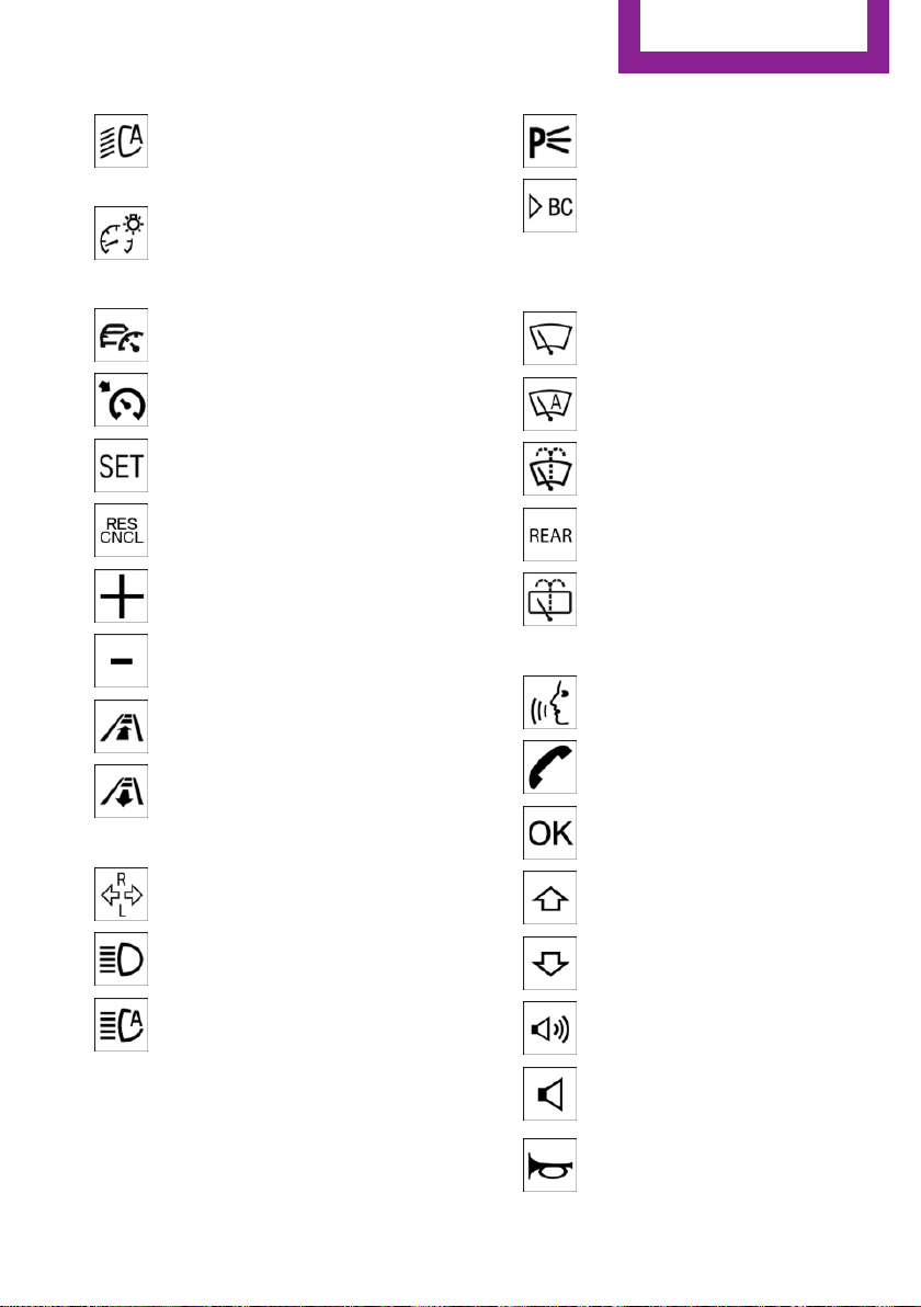
5 Steering wheel buttons, left
Camera-based cruise control on/
off 139
Cruise control on/off 145
Cruise control: store speed
Pausing, continuing cruise control
Cruise control: increase speed
Cruise control: reduce speed
Camera-based cruise control: re‐
duce distance
Camera-based cruise control: in‐
crease distance
6 Steering column stalk, left
Turn signal 84
Roadside parking lights 113
Onboard computer 103
7 Instrument cluster 94
8 Steering column stalk, right
Windshield wipers 85
Rain sensor 86
Cleaning windows 86
Rear window wiper 87
Clean the rear window 87
9 Steering wheel buttons, right
Voice activation 27
Telephone
Confirm the selection 103
Move selection up 103
High beams, head‐
light flasher 84
High-beam Assistant 114
Online Edition for Part no. 01 40 2 976 545 - X/16
Move selection down 103
Increase volume
Reduce volume
10 Horn, entire surface
15
Page 16
AT A GLANCE
11 Adjust the steering wheel 71 12 Unlock hood 221
Cockpit
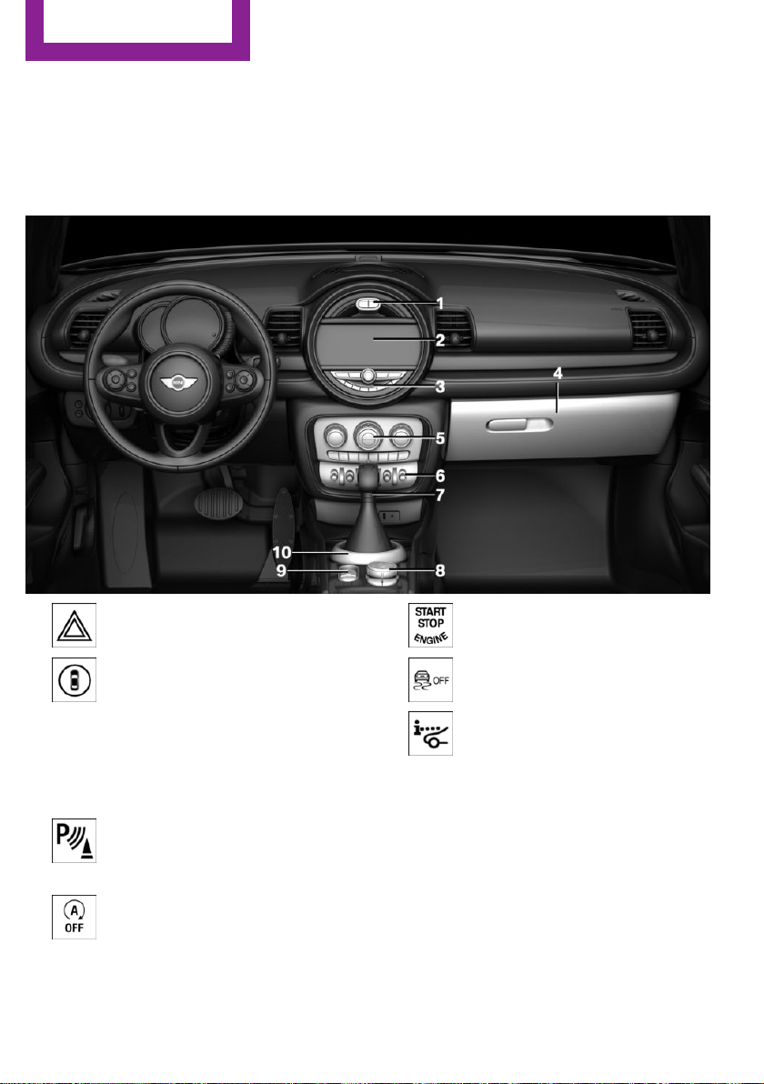
In the vicinity of the center console
1 Hazard warning system 242
Intelligent Safety 127
2 Control Display 18
3 Radio/Multimedia
4 Glove compartment 172
5 Climate control 157
6 PDC Park Distance Control 147
Rearview camera 150
Parking assistant 153
Auto Start/Stop function 80
16
Online Edition for Part no. 01 40 2 976 545 - X/16
Start/stop the engine and switch
the ignition on/off 78
DSC Dynamic Stability Con‐
trol 135
Head-up Display 108
7 Steptronic transmission selector lever 89
Manual transmission selector lever 89
8 Controller with buttons 19
9 Parking brake 82
10 MINI Driving Modes switch 137
Page 17
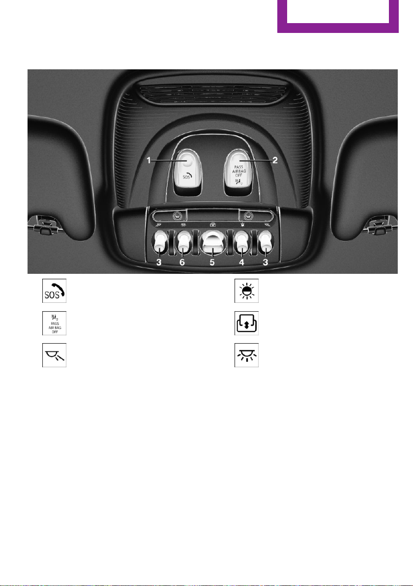
In the vicinity of the roofliner
Cockpit
AT A GLANCE
1 Emergency Request
2 Indicator light, front-seat passen‐
ger airbag 121
3 Reading lights 116
4 Ambient light 116
5 Panoramic glass sunroof 60
6 Interior lights 116
Online Edition for Part no. 01 40 2 976 545 - X/16
17
Page 18
AT A GLANCE
Onboard monitor
Onboard monitor
Vehicle features and op‐
tions
This chapter describes all standard, countryspecific and optional features offered with the
series. It also describes features that are not
necessarily available in your vehicle, e. g., due
to the selected options or country versions. This
also applies to safety-related functions and sys‐
tems. When using these functions and systems,
the applicable laws and regulations must be
observed.
Concept
The onboard monitor combines the functions
of a multitude of switches. Thus, these func‐
tions can be operated from a central location.
Safety information
WARNING
Operating the integrated information sys‐
tems and communication devices while driving
can distract from traffic. It is possible to lose
control of the vehicle. There is a risk of an acci‐
dent. Only use the systems or devices when the
traffic situation allows. If necessary, stop and
use the systems and devices while the vehicle is
stationary.◀
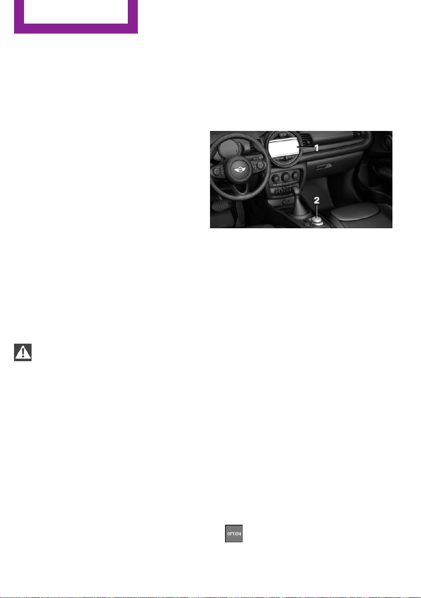
Operation
Overview
1 Control Display
2 Controller with buttons and touchpad
Control Display
General information
To clean the Control Display, follow the care in‐
structions.
Do not place objects close to the Control Dis‐
play; otherwise, the Control Display can be
damaged.
In the case of very high temperatures on the
Control Display, for instance due to intense so‐
lar radiation, the brightness may be reduced
down to complete deactivation. Once the tem‐
perature is reduced, for instance through
shadow or climate control system, the normal
functions are restored.
18
Switching on
Switch on the ignition.
1.
2. Press the controller.
Switching off
1. Press button.
Online Edition for Part no. 01 40 2 976 545 - X/16
Page 19

2. "Turn off control display"
Onboard monitor
Buttons on the controller
AT A GLANCE
Controller
General information
The buttons can be used to open the menus di‐
rectly. The controller can be used to select
menu items and enter the settings.
Some functions of the onboard monitor can be
operated using the touchpad on the controller,
refer to page 23:
Operation
▷ Turn.
▷ Press.
Button Function
Press once: call up main menu.
Press twice: open recently used me‐
nus.
Open the Communication menu.
Open the Media/Radio menu.
Open destination input menu for navi‐
gation.
Open navigation map.
Open the previous display.
Open the Options menu.
Operating with the con‐
troller
▷ Move in four directions.
Online Edition for Part no. 01 40 2 976 545 - X/16
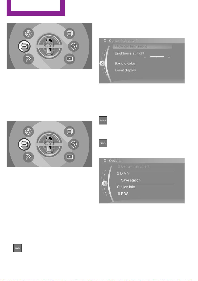
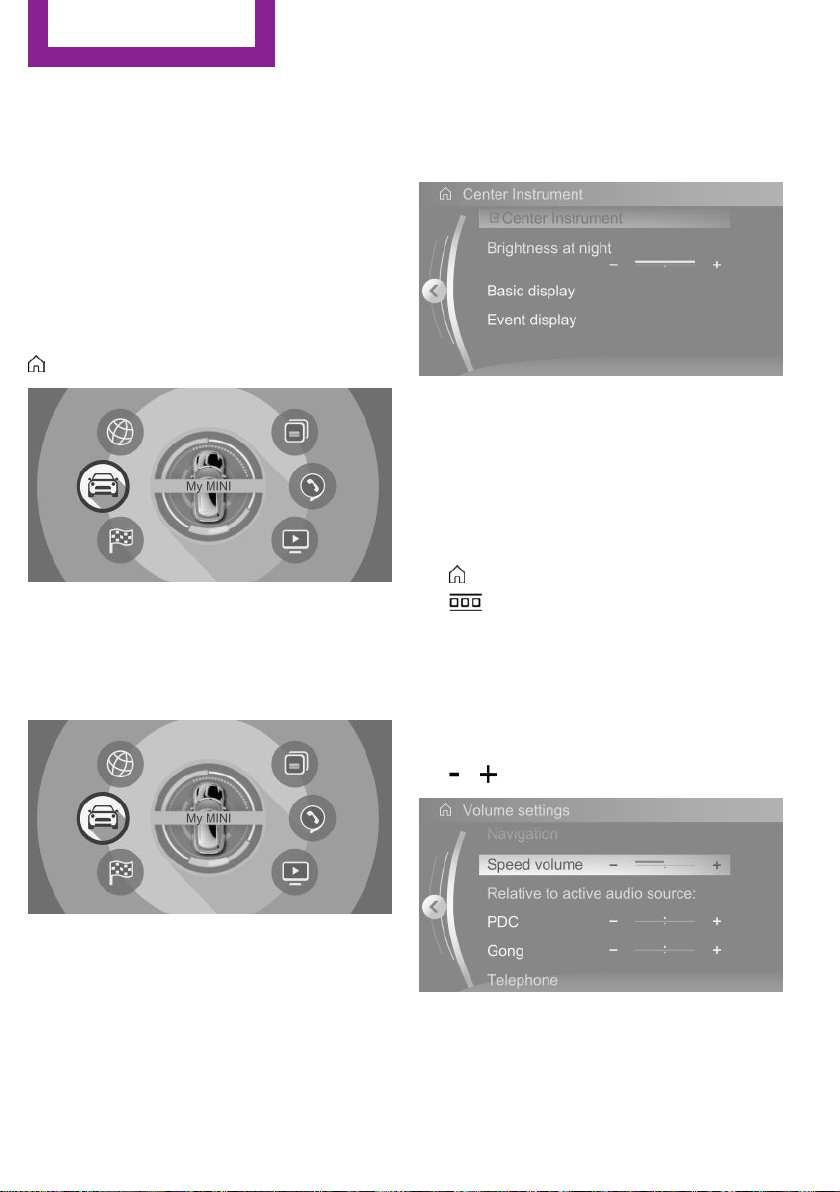
Opening the main menu
Press button.
19
Page 20
AT A GLANCE
The main menu is displayed.
All onboard monitor functions can be called up
via the main menu.
Onboard monitor
Selecting menu items
Highlighted menu items can be selected.
Turn the controller until the desired menu
1.
item is highlighted.
▷ Move the controller to the right.
New display is opened.
The arrow indicates that additional panels can
be opened.
Opening recently used menus
The recently used menus can be displayed.
Press button twice.
Opening the Options menu
Press button.
2. Press the controller.
Menu items in the Owner's Manual
In the Owner's Manual, menu items that can be
selected are set in quotation marks, for in‐
stance "System settings".
Changing between panels
After a menu item is selected, for instance
"System settings", a new panel is displayed.
▷ Move the controller to the left.
Closes current panel and shows previous
display.
▷
20
Press button.
The previous display opens.
Online Edition for Part no. 01 40 2 976 545 - X/16
The "Options" menu is displayed.
The Options menu consists of various areas:
▷ Screen settings, for instance "Split screen".
▷ Control options for the selected main
menu, for instance for "Media/Radio".
▷ If applicable, further operating options for
the selected menu, for instance "Save
station".
Changing settings
Select a field.
1.
Page 21
Onboard monitor
AT A GLANCE
2. Turn the controller until the desired setting
is displayed.
3. Press the controller.
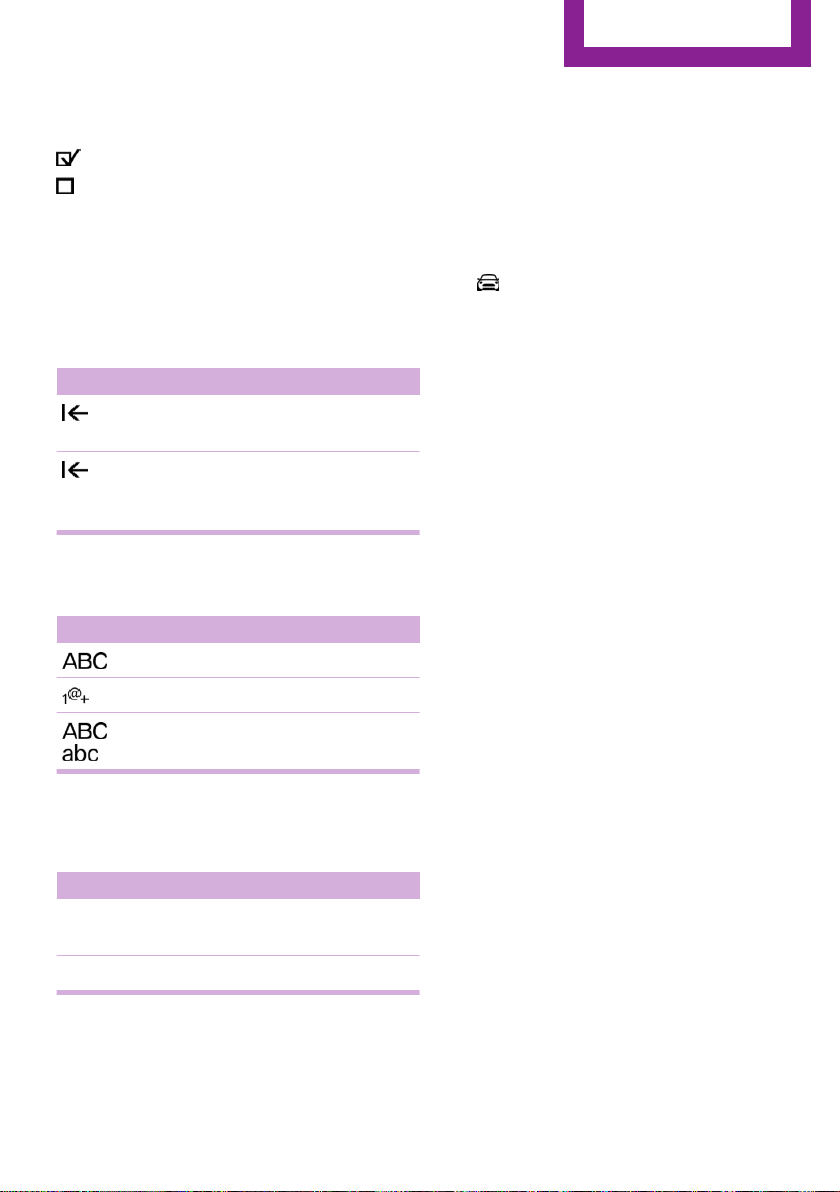
Activating/deactivating the functions
Several menu items are preceded by a check‐
box. It indicates whether the function is acti‐
vated or deactivated. Selecting the menu item
activates or deactivates the function.
Function is activated.
Function is deactivated.
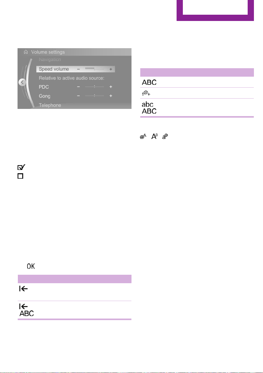
Entering letters and numbers
General information
Letters and numbers can be entered via the
controller.
The keyboard's display changes automatically.
Switching between upper/lower case,
numbers and characters
Depending on the menu, you can switch be‐
tween entering upper and lower case letters
and numbers:
Symbol Function
Enter the letters.
Enter the numbers.
or
Without navigation system
Select the symbol.
Change between capital and
lower-case letters.
Entry comparison
When entering names and addresses, the
choice is narrowed down with every letter en‐
tered and letters may be added automatically.
Entries are continuously compared with data
stored in the vehicle.
▷ Only those letters are offered during entry
for which data is available.
▷ Destination search: place names can be en‐
tered in all languages that are available on
the Control Display.
Input
Turn the controller: select letters or num‐
1.
bers.
2. : confirm entry.
Symbol Function
Press the controller: delete let‐
ters or number.
or
Hold the controller down: delete
all letters or numbers.
Online Edition for Part no. 01 40 2 976 545 - X/16
Using alphabetical lists
For alphabetical lists with more than 30 entries,
the letters for which there is an entry are dis‐
played at the left edge.
Turn the controller to the left or right
1.
quickly.
All letters for which there are entries are
displayed on the left edge.
2. Select the first letter of the desired entry.
The first entry of the selected letter is dis‐
played.
21
Page 22
AT A GLANCE
Onboard monitor
Operating via touchscreen
General information
The Control Display is equipped with a
touchscreen.
Touch screen with your fingers. Do not use any
objects.
Opening the main menu
Tap on symbol.
All onboard monitor functions can be called up
via the main menu.
Selecting menu items
Tap desired menu item.
Changing between panels
After a menu item is selected, a new panel is
displayed.
The arrow indicates that additional panels can
be opened.
▷ Swipe to the left.
▷ Tap on symbol.
New display is opened.
Opening recently used menus
Tap on symbol.
1.
2. Tap on symbol.
Changing settings
Settings such as volumes can be changed via
the touchscreen.
▷ Slide in the selected field to the right or left,
until the desired setting is displayed.
▷ , Tap on symbol.
Menu items in the Owner's Manual
In the Owner's Manual, menu items that can be
selected are set in quotation marks, for in‐
stance "System settings".
22
Online Edition for Part no. 01 40 2 976 545 - X/16
Activating/deactivating the functions
Several menu items are preceded by a check‐
box. It indicates whether the function is acti‐
Page 23
Onboard monitor
AT A GLANCE
vated or deactivated. Selecting the menu item
activates or deactivates the function.
Function is activated.
Function is deactivated.
Entering letters and numbers
General information
Letters and numbers can be entered using the
controller or the touchscreen.
The keyboard's display changes automatically.
Symbol Function
Tapping the symbol: delete the letter
or number.
Tapping and holding the symbol for
an extended period: delete all letters
or numbers.
Switching between upper/lower case,
numbers and characters
Symbol Function
Enter the letters.
Enter the numbers.
or
Change between capital and
lower-case letters.
Operating navigation map
The navigation map can be moved with the
touchscreen.
Function Operation
Enlarge/shrink
map.
Rotate map. Move two fingers in a circle.
Drag in or out with the fin‐
gers.
Touchpad
General information
Some functions of the onboard monitor can be
operated using the touchpad on the controller:
Selecting functions
1. "My MINI"
2. "System settings"
3. "Touchpad"
4. Select the desired function.
▷ "Speller": enter letters and numbers.
▷ "Map": using the map.
▷ "Search fields": write letters without se‐
lecting the list field.
▷ "Audio feedback": pronounces entered
letters and numbers.
Entering letters and numbers
Entering letters requires some practice at the
beginning. When entering, pay attention to the
following:
▷ The system distinguishes between upper
and lower-case letters and numbers. To
make entries, it may be necessary to
change between upper and lower-case let‐
ters, numbers and characters, refer to
page 21.
▷ Enter characters as they are displayed on
the Control Display.
▷ Always enter associated characters, such as
accents or periods so that the letter can be
clearly recognized. The set language deter‐
mines what input is possible. Where neces‐
sary, enter special characters via the con‐
troller.
▷ To delete a character, swipe to the left on
the touchpad.
▷ To enter a blank space, swipe to the right in
the center of the touchpad.
Online Edition for Part no. 01 40 2 976 545 - X/16
23
Page 24
AT A GLANCE
Onboard monitor
▷ To enter a hyphen, swipe to the right in the
upper area of the touchpad.
▷ To enter an underscore, swipe to the right
in the lower area of the touchpad.
Using the map
The map in the navigation system can be
moved via the touchpad.
Function Operation
Move map. Swipe in the appropriate di‐
rection.
Enlarge/shrink
map.
Display menu. Tap once.
Drag in or out on the touch‐
pad with fingers.
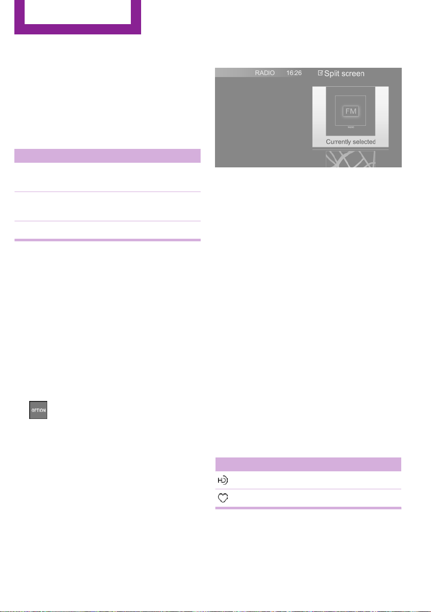
Split screen
General information
Additional information can be displayed on the
right side of the split screen, for instance infor‐
mation from the onboard computer.
In the divided screen view, the so-called split
screen, this information remains visible even
when switching to another menu.
Switching the split screen on/off
1. Press button.
2. "Split screen"
Selecting the display
The display can be selected in menus, where
the split screen is supported.
Move the controller to the right until the
1.
split screen is selected.
2. Press the controller.
3. Select the desired setting.
Specifying the number of displays
It is possible to specify the number of displays.
Move the controller to the right until the
1.
split screen is selected.
2. Press the controller.
3. "Personalize menu"
4. Select the desired setting.
5. Move the controller to the left.
Status information
General information
The status field can be found in the upper area
of the Control Display. Status information is dis‐
played in the form of symbols.
Status field symbols
Radio
Symbol Meaning
HD Radio station is being received.
Satellite radio is switched on.
24
Online Edition for Part no. 01 40 2 976 545 - X/16
Page 25
Onboard monitor
AT A GLANCE
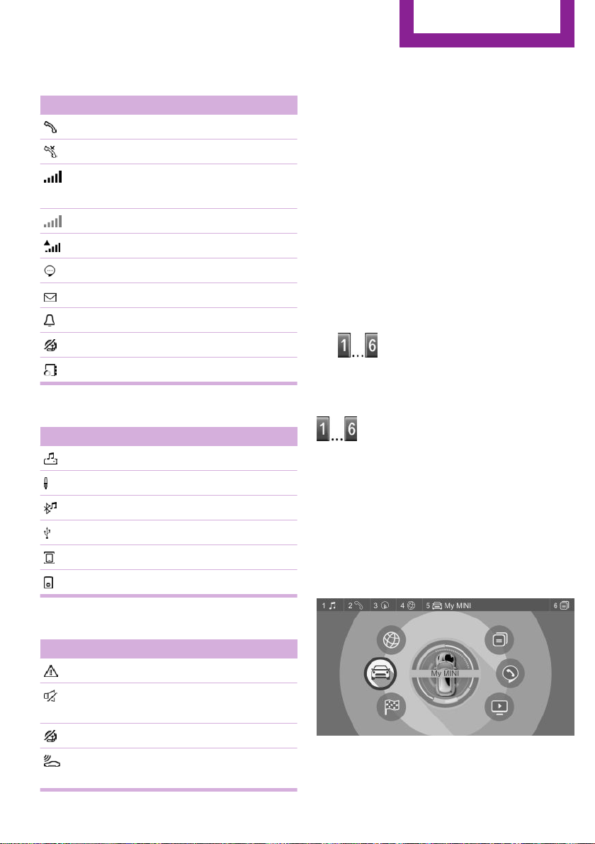
Telephone
Symbol Meaning
Incoming or outgoing call.
Missed call.
Signal strength of cellular network.
Symbol flashes: network search.
Cellular network is not available.
Roaming is active.
SMS text message received.
Message received.
Reminder.
Sending not possible.
Contacts are loaded.
Entertainment
Symbol Meaning
Music collection.
AUX-IN port.
Programmable memory buttons
General information
The onboard monitor functions can be stored
on the programmable memory buttons and
called up directly, for instance radio stations,
navigation destinations, phone numbers and
menu entries.
Settings are stored for the driver profile cur‐
rently used.
Saving a function
Select the function via the onboard moni‐
1.
tor.
2.
Running a function
This means, for instance that the number is di‐
aled when a phone number is selected.
Press and hold the desired button,
until a signal sounds.
Press button.
The function will work immediately.
Bluetooth audio.
USB audio interface.
Mobile phone audio interface.
iPod.
Additional symbols
Symbol Meaning
Check Control message.
The sound output has been switched
off.
Encrypted connection not active.
Request for the current vehicle posi‐
tion.
Online Edition for Part no. 01 40 2 976 545 - X/16
Displaying the key assignment
Touch buttons with finger. Do not wear gloves
or use objects.
The button assignment is displayed at the top
edge of screen.
25
Page 26

AT A GLANCE
Onboard monitor
Deleting the button assignments
1. Press buttons 1 and 6 simultaneously for
approx. 5 seconds.
2. "OK"
26
Online Edition for Part no. 01 40 2 976 545 - X/16
Page 27

Voice activation system
Voice activation system
AT A GLANCE
Vehicle features and op‐
tions
This chapter describes all standard, countryspecific and optional features offered with the
series. It also describes features that are not
necessarily available in your vehicle, e. g., due
to the selected options or country versions. This
also applies to safety-related functions and sys‐
tems. When using these functions and systems,
the applicable laws and regulations must be
observed.
The concept
▷ Most functions displayed on the Control
Display can be operated by voice com‐
mands via the voice activation system. The
system supports you with announcements
during input.
▷ Functions that can only be used when the
vehicle is stationary cannot be used via the
voice activation system.
▷ The system uses a special microphone on
the driver's side.
▷ ›...‹ Verbal instructions in the Owner's Man‐
ual to use with the voice activation system.
Requirements
Using the voice activa‐
tion system
Activating the voice activation system
1.
2. Wait for the signal.
3. Say the command.
This symbol in the instrument cluster indi‐
cates that the voice activation system is active.
If no other commands are available, operate
the function via the onboard monitor.
Press button on the steering wheel.
Terminating the voice activation
system
Press the button on the steering wheel
or ›Cancel‹.
Possible commands
Most menu items on the Control Display can be
voiced as commands.
Commands from other menus can also be spo‐
ken.
You may select list entries such as phone list
entries via voice activation. Read these list en‐
tries out loud exactly as they are shown in the
respective list.
Via the Control Display, set a language that is
also supported by the voice activation system
so that the spoken commands can be identi‐
fied.
To set the language, refer to page 30.
Online Edition for Part no. 01 40 2 976 545 - X/16
Displaying possible commands
The following is displayed in the top area of the
Control Display:
▷ Some possible commands for the current
menu.
▷ Some possible commands from other me‐
nus.
▷ Status of the voice recognition.
27
Page 28
AT A GLANCE
Voice activation system
▷ Encrypted connection is not available.
Help on the voice activation system
▷ To have information on the operating prin‐
ciple of the voice activation system read
out loud: ›General information on voice
control‹.
▷ To have help for the current menu read out
loud: ›Help‹.
Example: opening the tone settings
The commands of the menu items are spoken
just as they are selected via the controller.
Turn on the Entertainment sound output, if
1.
needed.
2.
3. ›Radio‹
4. ›Tone‹
Press button on the steering wheel.
Settings
Setting the voice dialog
You can set the system to use standard dialog
or a short version.
The short version of the voice dialog plays back
short messages in abbreviated form.
"My MINI"
1.
2. "System settings"
3. "Language"
4. "Speech mode:"
5. Select the desired setting.
Selecting the input language
For some languages, the input language can be
selected.
1. "My MINI"
2. "System settings"
3. "Language"
4. "Voice control:"
5. Select the desired setting.
Activating voice recognition via the
server
The voice recognition feature via the server
provides a dictation function and a natural
method of entering destinations while improv‐
ing the quality of voice recognition. To use the
functions, data is transmitted to a service pro‐
vider via an encrypted connection and stored
locally there.
"My MINI"
1.
2. "System settings"
3. "Language"
4. "Server speech recognition"
Speaking during voice output
It is possible to answer during inquiries of the
voice activation system. The function can be
deactivated if inquiries are often undesirably
interrupted, for instance due to background
noise or talking.
"My MINI"
1.
2. "System settings"
3. "Language"
4. "Speaking during voice output"
Adjusting the volume
28
Turn the volume button during the spoken in‐
structions until the desired volume is set.
▷ The volume remains constant even if the
volume of other audio sources is changed.
Online Edition for Part no. 01 40 2 976 545 - X/16
Page 29

Voice activation system
▷ The volume is stored for the profile cur‐
rently used.
Information on Emer‐
gency Requests
Do not use the voice activation system to ini‐
tiate an Emergency Request. In stressful situa‐
tions, the voice and vocal pitch can change.
This can unnecessarily delay the establishment
of a phone connection.
Environmental condi‐
tions
▷ Say the commands, numbers, and letters
smoothly and with normal volume, empha‐
sis, and speed.
▷ Always say commands in the language of
the voice activation system.
▷ Keep the doors, windows, and glass sun‐
roof closed to prevent noise interference.
▷ Avoid making other noise in the vehicle
while speaking.
AT A GLANCE
Online Edition for Part no. 01 40 2 976 545 - X/16
29
Page 30

AT A GLANCE
General settings
General settings
Vehicle features and op‐
tions
This chapter describes all standard, countryspecific and optional features offered with the
series. It also describes features that are not
necessarily available in your vehicle, e. g., due
to the selected options or country versions. This
also applies to safety-related functions and sys‐
tems. When using these functions and systems,
the applicable laws and regulations must be
observed.
Language
Setting the language
Via the onboard monitor:
"My MINI"
1.
2. "System settings"
3. "Language"
4. "Language:"
5. Select the desired setting.
The setting is stored for the driver profile cur‐
rently used.
Setting the voice dialog
Voice dialog for the voice activation system, re‐
fer to page 28.
Time
4. "Time zone:"
5. Select the desired setting.
The setting is stored for the driver profile cur‐
rently used.
Setting the time
Via the onboard monitor:
1. "My MINI"
2. "System settings"
3. "Date and time"
4. "Time:"
5. Turn the controller until the desired hours
are displayed.
6. Press the controller.
7. Turn the controller until the desired mi‐
nutes are displayed.
8. Press the controller.
The setting is stored for the driver profile cur‐
rently used.
Setting the time format
Via the onboard monitor:
"My MINI"
1.
2. "System settings"
3. "Date and time"
4. "Time format:"
5. Select the desired setting.
The setting is stored for the driver profile cur‐
rently used.
Setting the time zone
Via the onboard monitor:
"My MINI"
1.
2. "System settings"
3. "Date and time"
30
Online Edition for Part no. 01 40 2 976 545 - X/16
Page 31

General settings
AT A GLANCE
Date
Setting the date
Via the onboard monitor:
1. "My MINI"
2. "System settings"
3. "Date and time"
4. "Date:"
5. Turn the controller until the desired day is
displayed.
6. Press the controller.
7. Make the necessary settings for the month
and year.
The setting is stored for the driver profile cur‐
rently used.
Setting the date format
Via the onboard monitor:
"My MINI"
1.
2. "System settings"
3. "Date and time"
4. "Date format:"
5. Select the desired setting.
The setting is stored for the driver profile cur‐
rently used.
Setting the units of measurement
You can set the units of measurement for some
values, for example, fuel consumption, distan‐
ces and temperature.
Via the onboard monitor:
"My MINI"
1.
2. "System settings"
3. "Units"
4. Select the desired menu item.
5. Select the desired setting.
The setting is stored for the driver profile cur‐
rently used.
Activating/deactivating popup windows
For some functions, popup windows are dis‐
played automatically on the Control Display.
Some of these popup windows can be acti‐
vated or deactivated.
Via the onboard monitor:
1. "My MINI"
2. "System settings"
3. "Pop-ups"
4. Select the desired setting.
The setting is stored for the driver profile cur‐
rently used.
Control Display
Brightness
Via the onboard monitor:
"My MINI"
1.
2. "System settings"
3. "Displays"
4. "Control display"
5. "Brightness at night"
6. Turn the controller until the desired bright‐
ness is set.
7. Press the controller.
The setting is stored for the driver profile cur‐
rently used.
Depending on the light conditions, the bright‐
ness settings may not be clearly visible.
Online Edition for Part no. 01 40 2 976 545 - X/16
31
Page 32

AT A GLANCE
General settings
Screensaver
If no entries are made via the onboard monitor,
a screensaver can be displayed after an adjust‐
able time.
Via the onboard monitor:
1. "My MINI"
2. "System settings"
3. "Displays"
4. "Control display"
5. "Screensaver"
6. Select the desired setting.
The setting is stored for the driver profile cur‐
rently used.
Messages
Concept
The menu centrally displays all messages arriv‐
ing in the vehicle in list form.
General information
The following messages can be displayed:
▷ Traffic messages.
▷ Check Control messages.
▷ Communication messages, for example e-
mails, SMS text messages or reminders.
▷ Service requirements messages.
Messages are additionally displayed in the sta‐
tus field.
Retrieving messages
Via the onboard monitor:
"Notifications"
1.
2. Select the desired message.
The respective menu is opened, where the
message is displayed.
Deleting messages
All messages, except Check Control messages,
can be deleted from the list. Check Control
messages are displayed as long as they are rel‐
evant.
Via the onboard monitor:
1. "Notifications"
2. Select the desired message.
3.
4. "Delete this notification" or "Delete all
Press button.
notifications"
Settings
The following settings can be adjusted:
▷ Select the applications, from which mes‐
sages will be permitted.
▷ Sort the messages according to date or pri‐
ority.
Via the onboard monitor:
"My MINI"
1.
2. "System settings"
3. "Notifications"
4. Select the desired setting.
Data protection
Data transfer
Concept
The vehicle offers various functions which re‐
quire data to be transferred to MINI or a service
provider. The data transfer can be deactivated
for some functions.
General information
With data transfer deactivated, the respective
function cannot be used.
Only make these settings while stationary.
32
Online Edition for Part no. 01 40 2 976 545 - X/16
Page 33

General settings
AT A GLANCE
Activating/deactivating the data
transfer
Follow the instructions on the Control Display.
Via the Central Information Display (CID):
1. Switch on the ignition.
2. "My MINI"
3. "System settings"
4. "Data privacy"
5. Select the desired setting.
Deleting personal data in the vehicle
Concept
Depending on the usage, the vehicle saves per‐
sonal data, such as stored radio stations. This
personal data can be permanently deleted via
the onboard monitor.
General information
Depending on the equipment package, the fol‐
lowing data can be deleted:
▷ Driver profile settings.
▷ Stored radio stations.
▷ Stored Favorites buttons.
▷ Travel and onboard computer information.
▷ Music collection.
▷ Navigation, for instance stored destina‐
tions.
▷ Phone book.
▷ Office data, for instance voice notes.
▷ Login accounts.
Altogether, the deletion of the data can take up
to 15 minutes.
Functional requirement
Data can only be deleted while stationary.
Deleting data
Heed and follow the instructions on the Control
Display.
Via the Central Information Display (CID):
1. Switch on the ignition.
2. "My MINI"
3. "System settings"
4. "Data privacy"
5. "Delete personal data"
6. "Delete personal data"
7. "OK"
8. Exit and lock the vehicle.
After 15 minutes, the deletion process is com‐
pleted.
If not all of the data was deleted, repeat the
deletion.
Canceling deletion
Start the engine to cancel deletion of the data.
Connections
Concept
Mobile devices, such as mobile phones or lap‐
tops, can be connected and used in the vehicle
in various ways.
General information
The following connection types require onetime pairing with the vehicle:
▷ Bluetooth.
Paired devices are automatically recognized
later on and connected to the vehicle.
The following functions are possible:
Connection type Function
Mobile phone via
Bluetooth.
Audio player/smart‐
phone via Bluetooth
or USB port.
Making calls.
Office functions.
Playing music.
Online Edition for Part no. 01 40 2 976 545 - X/16
33
Page 34

AT A GLANCE
General settings
Connection type Function
Smartphone via USB
port
Smartphone via
Bluetooth or USB
port.
USB memory device
via USB port.
Playing videos.
Using apps.
Exporting and import‐
ing driver profiles.
Performing software
updates.
Exporting and import‐
ing stored trips.
Playing music.
Safety information
WARNING
Operating the integrated information sys‐
tems and communication devices while driving
can distract from traffic. It is possible to lose
control of the vehicle. There is a risk of an acci‐
dent. Only use the systems or devices when the
traffic situation allows. If necessary, stop and
use the systems and devices while the vehicle is
stationary.◀
Displaying the device list
All devices paired and/or connected with the
vehicle are displayed in the device list.
Via the onboard monitor:
"My MINI"
1.
2. "System settings"
3. "Mobile devices"
A symbol indicates, for which function a device
is used.
Symbol Function
"Telephone"
"Additional telephone"
Symbol Function
"Bluetooth® audio"
"Apps"
Bluetooth connection
Compatible devices
General information
Details on which mobile phones and mobile de‐
vices with a Bluetooth interface are supported
can be obtained at www.miniusa.com/blue‐
tooth.
Malfunctions may occur with devices not listed
or deviating software versions.
Displaying the vehicle identification number
and software part number
The vehicle identification number and software
part number are needed to determine which
devices are supported. The software version of
the mobile phone may also be required.
Via the onboard monitor:
"My MINI"
1.
2. "System settings"
3. "Mobile devices"
4. "Settings"
5. "Bluetooth® info"
6. "System information"
A software update, refer to page 37, can be
performed, if needed.
Functional requirements
▷ Compatible device, refer to page 34.
▷ The device is ready for operation.
▷ Bluetooth is activated on the device and in
the vehicle, refer to page 35.
▷ Bluetooth pre-settings may be required on
the device, for instance visibility, refer to
the owner's manual of the device.
34
Online Edition for Part no. 01 40 2 976 545 - X/16
Page 35

General settings
AT A GLANCE
▷ A number with at least four and a maxi‐
mum of 16 digits should be defined as the
Bluetooth passkey. Required for one-time
pairing only.
Activating Bluetooth
Via the onboard monitor:
1. "My MINI"
2. "System settings"
3. "Mobile devices"
4. "Settings"
5. "Bluetooth®"
Activating/deactivating telephone
functions
To use all supported functions of a mobile
phone, the following functions must be acti‐
vated prior to pairing.
Via the onboard monitor:
"My MINI"
1.
2. "System settings"
3. "Mobile devices"
4. "Settings"
5. Select desired setting:
▷ "Office"
Activate function to transmit short mes‐
sages, e-mails, calendars, tasks, notes,
and reminders to the vehicle. Costs can
be incurred by transmitting all data to
the vehicle.
▷ "Contact images"
Activate function to show the contact
pictures.
6. Move the controller to the left.
Pairing the mobile device with the
vehicle
Via the onboard monitor:
1. "My MINI"
2. "System settings"
3. "Mobile devices"
4. "Connect new device"
5. Select the functions for which the device is
to be used:
▷ "Telephone"
▷ "Bluetooth® audio"
▷ "Apps"
The Bluetooth name of the vehicle is dis‐
played on the Control Display.
6. Search for Bluetooth devices in the vicinity
of the mobile device.
The Bluetooth name of the vehicle appears
on the mobile device display.
Select the Bluetooth name of the vehicle.
7. Depending on the mobile device, a control
number is displayed or the control number
must be entered.
▷ Compare the control number displayed
on the Control Display with the control
number on the display of the device.
Confirm the control number on the de‐
vice and on the Control Display.
▷ Enter and confirm the same control
number on the device and via the on‐
board monitor.
The device is connected and displayed in
the device list.
If connection was not successful: Frequently
Asked Questions, refer to page 38.
USB connection
General information
Mobile devices with USB port can be connected
to the USB interface.
Online Edition for Part no. 01 40 2 976 545 - X/16
35
Page 36

AT A GLANCE
General settings
▷ Mobile phones supported by the USB inter‐
face.
▷ Audio devices with USB port, for instance
MP3 player.
▷ USB storage devices.
Common file systems are supported. FAT32
and exFAT are the recommended formats.
Information about compatible USB media can
be found at www.miniusa.com/bluetooth.
The following applications are possible:
▷ Exporting and importing driver profiles, re‐
fer to page 52.
▷ Playing music files via USB audio.
▷ Playing videos via USB video.
▷ Loading of software updates, refer to
page 37.
Observe the following when connecting:
▷ Do not use force when plugging the con‐
nector into the USB interface.
▷ Use a flexible adapter cable.
▷ Protect the USB storage device against me‐
chanical damage.
▷ Due to the large number of USB media
available on the market, it cannot be guar‐
anteed that every device is operable on the
vehicle.
▷ Do not expose USB media to extreme envi‐
ronmental conditions, such as very high
temperatures; refer to the owner's manual
of the device.
▷ Due to the many different compression
techniques, proper playback of the media
stored on the USB storage device cannot be
guaranteed in all cases.
▷ A connected USB storage device will be
supplied with charging current via the USB
interface if the device supports this. At
higher temperatures, the USB storage de‐
vice may cause a reduction in the charging
current.
▷ To ensure proper transmission of the stored
data, do not charge a USB storage device
via the onboard socket, when it is con‐
nected to the USB interface.
▷ Depending on how the USB storage device
should be used, settings may be required
on the USB storage device, refer to the
owner's manual of the device.
Not compatible USB media:
▷ USB hard drives.
▷ USB hubs.
▷ USB memory card readers with multiple in‐
serts.
▷ HFS-formatted USB media.
▷ Devices such as fans or lights.
Connecting the device
Connect the USB storage device using a suita‐
ble adapter cable to a USB interface, refer to
page 170.
The USB storage device is connected to the ve‐
hicle and displayed in the device list.
Additional functions
Following the initial pairing
▷ The device is connected with the vehicle
within a short period of time if the engine is
running or ignition is switched on.
▷ The data stored on the SIM card or in the
mobile phone are transferred to the vehicle
after recognition.
▷ For some devices, certain settings may be
necessary, for instance authorization, see
owner's manual of the device.
▷ After one-time pairing, the devices are au‐
tomatically recognized and reconnected
when the ignition is switched on.
Configuring the device
Functions can be activated or deactivated for
paired and connected devices.
36
Online Edition for Part no. 01 40 2 976 545 - X/16
Page 37

General settings
AT A GLANCE
Via the onboard monitor:
1. "My MINI"
2. "System settings"
3. "Mobile devices"
4. Select the desired device.
5. Select the desired setting.
If a function is assigned to a device, the func‐
tion will be deactivated where appropriate for a
device that is already connected and the device
will be disconnected.
Connecting a specific device
Via the onboard monitor:
"My MINI"
1.
2. "System settings"
3. "Mobile devices"
4. Select device.
5. "Connect device"
The functions that were assigned to the device
before disconnecting are assigned to the de‐
vice when it is reconnected. If the device is al‐
ready connected, these functions are deacti‐
vated.
Disconnecting the device
The connection of the device to the vehicle is
disconnected.
The device remains paired and can be con‐
nected again, refer to page 37.
Via the onboard monitor:
"My MINI"
1.
2. "System settings"
3. "Mobile devices"
4. Select device.
5. "Disconnect device"
Deleting the device
The device is disconnected and removed from
the device list.
Via the onboard monitor:
1. "My MINI"
2. "System settings"
3. "Mobile devices"
4. Select device.
5. "Delete device"
Swapping the telephone and additional
phone
If two mobile phones are connected to the ve‐
hicle, the functions of the phone and additional
phone can be switched.
Via the onboard monitor:
"My MINI"
1.
2. "System settings"
3. "Mobile devices"
4. "Settings"
5. "Swap telephone/additional tel."
Software update
General information
The vehicle supports a large number of mobile
devices, for instance mobile phones and MP3
players. Software updates are available for
many of the supported devices. The vehicle is
maintained up-to-date via regular vehicle soft‐
ware updates.
Updates and related current information is
available on the Internet at www.mini.com/
update.
Displaying the installed software
version
The software version installed in the vehicle is
displayed.
Via the onboard monitor:
"My MINI"
1.
2. "System settings"
Online Edition for Part no. 01 40 2 976 545 - X/16
37
Page 38

AT A GLANCE
General settings
3. "Software update"
4. "Show current version"
If an update has been carried out before, select
the desired version to display additional infor‐
mation.
Updating software via USB
The software may only be updated when the
vehicle is stationary.
Via the onboard monitor:
1. Store the file for the software update in the
main directory of a USB flash drive.
2. Connect the USB data storage to a USB in‐
terface.
3. "My MINI"
4. "System settings"
5. "Software update"
6. "Update software"
7. "USB"
8. "Install software"
9. "OK"
10. Wait for the update to complete.
11. Confirm system restart.
Restoring the software version
The software version before the last software
update and the version before the first software
update can be restored.
The software may only be restored when the
vehicle is stationary.
Via the onboard monitor:
"My MINI"
1.
2. "System settings"
3. "Software update"
4. "Restore software"
5.
▷ "Previous version"
The previous software version is re‐
stored.
▷ "Default software settings"
The first software version is restored.
6. "Remove software"
7. "OK"
8. Wait for restore.
9. Confirm system restart.
Frequently asked questions
Information on compatible mobile phones, re‐
fer to page 34.
All requirements are met and all required steps
were completed in the specified order. Despite
that, the mobile device does not function as ex‐
pected.
In this case, the following explanations can
help:
Why could the mobile phone not be paired or
connected?
▷ There are too many Bluetooth devices con‐
nected to the mobile phone or vehicle.
Delete connections with other devices, if
needed.
▷ Delete all known Bluetooth connections
from the device list on the mobile phone
prior to connecting.
Start new device search.
▷ The mobile phone is in power-save mode
or has only a limited remaining battery life.
Charge the mobile phone in the snap-in
adapter, wireless charging tray or via the
charging cable.
▷ Depending on the mobile phone, it is possi‐
ble that only one mobile phone can be con‐
nected to the vehicle.
Unpair the connected mobile phone from
the vehicle and pair and connect only one
mobile phone.
Why does the mobile phone no longer react?
▷ The applications on the mobile phone do
not function anymore.
Switch the mobile phone off and on again.
38
Online Edition for Part no. 01 40 2 976 545 - X/16
Page 39

General settings
AT A GLANCE
▷ Possibly too high or too low ambient tem‐
peratures for mobile phone operation.
Do not subject the mobile phone to ex‐
treme ambient temperatures.
Why are no telephone functions available?
▷ The mobile phone may not be properly
configured, for instance as Bluetooth audio
device.
Connect the mobile phone with the tele‐
phone or additional phone function.
Why are no or not all phone book entries dis‐
played or why are they incomplete?
▷ Transmission of the phone book entries is
not yet complete.
▷ It is possible that only the phone book en‐
tries of the mobile phone or the SIM card
are transmitted.
▷ It may not be possible to display phone
book entries with special characters.
▷ It may not be possible to transmit contacts
from social networks.
▷ The number of phone book entries to be
stored is too high.
▷ Data volume of the contact too large, for
instance due to stored information such as
notes.
Reduce the data volume of the contact.
▷ A mobile phone can only be connected as
audio source or as telephone.
Configure the mobile phone and connect it
with the telephone or additional phone
function.
Why is the phone connection quality poor?
▷ The strength of the Bluetooth signal on the
mobile phone can be adjusted, depending
on the mobile phone.
▷ Insert the mobile phone into the snap-in
adapter or place it in the area of the center
console.
▷ Insert mobile phone into the wireless
charging tray.
▷ Adjust the volume of the microphone and
loudspeakers separately.
If all points in this list have been checked and
the required function is still not available, con‐
tact the hotline, a dealer’s service center or an‐
other qualified service center or repair shop.
Online Edition for Part no. 01 40 2 976 545 - X/16
39
Page 40

AT A GLANCE
Integrated Owner's Manual in the vehicle
Integrated Owner's Manual in the vehicle
Vehicle features and op‐
tions
This chapter describes all standard, countryspecific and optional features offered with the
series. It also describes features that are not
necessarily available in your vehicle, e. g., due
to the selected options or country versions. This
also applies to safety-related functions and sys‐
tems. When using these functions and systems,
the applicable laws and regulations must be
observed.
Integrated Owner's Man‐
ual in the vehicle
Concept
The Integrated Owner's Manual specifically de‐
scribes features and functions found in the ve‐
hicle. It can be displayed on the Control Display.
Components of the Integrated Owner's
Manual
General information
The Integrated owner's manual consists of four
parts, which offer various levels of information
or possible access.
Quick Reference Guide
The Quick Reference Guide provides informa‐
tion how to operate the car, how to use basic
vehicle functions and what to do in case of a
breakdown. This information can also be dis‐
played while driving.
Search by images
Image search provides information and de‐
scriptions. This is helpful when the terminology
for a feature is not at hand.
Owner's Manual
Search for information and descriptions by en‐
tering terms selected from the index.
Videos
The basic functions of selected systems are ex‐
plained in the videos.
Select components
1. Press button.
2. "My MINI"
3. "Owner's Manual"
4. Select the desired setting.
Scrolling through the owner's manual
Turn the controller, until the next or previous
contents are displayed.
Context help - operating instructions
for the currently selected function
General information
The relevant information can be displayed di‐
rectly.
Opening via onboard monitor
Change directly to the Options menu from the
function on the Control Display:
1. Press button.
2. "Owner's Manual"
40
Online Edition for Part no. 01 40 2 976 545 - X/16
Page 41

Integrated Owner's Manual in the vehicle
AT A GLANCE
Opening when a Check Control
message is displayed
Directly from the Check Control message on the
Control Display:
"Owner's Manual"
Changing between a function and the
operating instructions
To switch from a function, for instance radio, to
the Owner's Manual on the Control Display and
to alternate between the two displays:
1.
2. "Owner's Manual"
3. Select the desired page in the Owner's
4.
5.
To alternate permanently between the last dis‐
played function and the last displayed page of
the Owner's Manual repeat steps 4 & 5. Opens
a new display every time.
Press button.
Manual.
Press button again to return to last
displayed function.
Press button to return to the page of
the Owner's Manual displayed last.
2.
Press and hold the desired button,
until a signal sounds.
Executing
Press button.
The Owner's Manual is displayed im‐
mediately.
Programmable memory buttons
General information
The Owner's Manual can be stored on the pro‐
grammable memory buttons and called up di‐
rectly.
Storing
Select the desired entry point via the on‐
1.
board monitor:
▷ "Quick reference"
▷ "Search by pictures"
▷ "Keyword search"
▷ "Animations"
Online Edition for Part no. 01 40 2 976 545 - X/16
41
Page 42

HANDLE ME.
Online Edition for Part no. 01 40 2 976 545 - X/16
Page 43

AT A GLANCE
CONTROLS
DRIVING TIPS
MOBILITY
REFERENCE
Online Edition for Part no. 01 40 2 976 545 - X/16
Page 44

CONTROLS
Opening and closing
Opening and closing
Vehicle features and op‐
tions
This chapter describes all standard, countryspecific and optional features offered with the
series. It also describes features that are not
necessarily available in your vehicle, e. g., due
to the selected options or country versions. This
also applies to safety-related functions and sys‐
tems. When using these functions and systems,
the applicable laws and regulations must be
observed.
Remote control
General information
The vehicle is supplied with two remote con‐
trols with integrated key.
Each remote control contains a replaceable
battery. Replacing the battery, refer to
page 46.
You may set the key functions depending on
the optional features and country-specific ver‐
sion. Settings, refer to page 55.
The vehicle stores personal settings for every
remote control. Personal Profile, refer to
page 52.
The remote controls hold information about re‐
quired maintenance. Service data in the remote
control, refer to page 229.
WARNING
Unlocking from the inside is only possible
with special knowledge.
Persons who spend a lengthy time in the vehi‐
cle while being exposed to extreme tempera‐
tures are at risk of injury or death. Do not lock
the vehicle from the outside when there are
people in it.◀
WARNING
Unattended children or animals can
cause the vehicle to move and endanger them‐
selves and traffic, e.g., due to the following ac‐
tions:
▷ Pressing the Start/Stop button.
▷ Releasing the parking brake.
▷ Opening and closing the doors or windows.
▷ Engaging selector lever position N.
▷ Using vehicle equipment.
There is a risk of accidents or injuries. Do not
leave children or animals unattended in the ve‐
hicle. Take the remote control with you when
exiting and lock the vehicle.◀
Overview
Safety information
WARNING
People or animals in the vehicle can lock
the doors from the inside and lock themselves
in. In this case, the vehicle cannot be opened
from the outside. There is a risk of injury. Take
the remote control with you so that the vehicle
can be opened from the outside.◀
44
Online Edition for Part no. 01 40 2 976 545 - X/16
1 Unlocking
2 Locking
3
Open split doors
4 Panic mode
Page 45

Opening and closing
CONTROLS
Unlocking
Press button on the remote control.
Depending on the settings, refer to page 55,
the following access points are unlocked.
▷ Driver's door and fuel filler flap.
Press the button of the remote control
again to unlock the other vehicle access
points.
▷ All doors, the split doors, and fuel filler flap.
In addition, the following functions are exe‐
cuted:
▷ The settings saved in the driver profile, re‐
fer to page 52, are applied.
▷ The interior lights, courtesy lights and the
MINI logo projection are activated.
These functions are not available if the inte‐
rior lights were switched off manually.
▷ The welcome lights are switched on, if this
function was activated.
▷ Automatically folded in exterior mirrors are
folded open. This function must be acti‐
vated in the settings, refer to page 55.
▷ The alarm system, refer to page 56, is
switched off.
The light functions may depend on the ambient
brightness.
Convenient opening
Press and hold this button on the re‐
mote control after unlocking.
The windows and the glass sunroof are opened,
as long as the button on the remote control is
pressed.
All doors, the split doors, and the fuel filler flap
are locked.
The alarm system, refer to page 56, is
switched on.
If the engine or ignition is still switched on
when you lock the vehicle, the vehicle horn
honks twice. In this case, the engine or ignition
must be switched off by means of the Start/
Stop button.
Switch on interior lights and courtesy
light
Press button on the remote control
with the vehicle locked.
The MINI logo projection is also switched on.
These functions are not available if the interior
lights were switched off manually.
The light functions may depend on the ambient
brightness.
If the button is pressed within 10 seconds of
when the vehicle was locked Interior motion
sensor and tilt alarm sensor of the anti-theft
warning system, refer to page 57, are turned
off. After locking, wait 10 seconds before press‐
ing the button again.
Split Doors
General information
To avoid locking it in the vehicle, do not place
the remote control in the cargo area.
Depending on your vehicle's equipment and
the country version, it is possible to specify
whether the doors are also unlocked when un‐
locking with the remote control. Adjusting the
settings, refer to page 55.
Locking
Close the driver's door.
1.
2.
Press button on the remote con‐
trol.
Safety information
WARNING
Body parts can be jammed when operat‐
ing the split doors. There is a risk of injury.
Make sure that the area of movement of the
Online Edition for Part no. 01 40 2 976 545 - X/16
45
Page 46

CONTROLS
Opening and closing
split doors is clear during opening and clos‐
ing.◀
NOTE
The split doors swivel back and to the
side when they open. There is a risk of damage
to property. Make sure that the area of move‐
ment of the split doors is clear during opening
and closing.◀
NOTE
Sharp-edged or pointed objects can hit
the rear window and heat conductors while
driving. There is a risk of property damage.
Cover the edges and ensure that pointed ob‐
jects do not hit the rear window.◀
Opening
1. Press button on the remote control
for approx. 1 second.
The right side of the split doors opens.
2.
Press button on the remote control
again for approx. 1 second.
The left side of the split doors opens.
The battery compartment is accessible.
3. Slide the integrated key in the cover of the
battery compartment and raise the cover.
4. Push battery in the direction of the arrow
using a pointed object and lift it out.
Panic mode
You can trigger the alarm system if you find
yourself in a dangerous situation.
Press button on the remote control
and hold for at least 3 seconds.
To switch off the alarm: press any button.
Replacing the battery
Remove the integrated key from the re‐
1.
mote control, refer to page 48.
2. Slide the integrated key into the opening
and raise the cover.
46
Online Edition for Part no. 01 40 2 976 545 - X/16
5. Insert a type CR 2032 battery with the posi‐
tive side facing up.
6. Insert lid and cover.
7. Push the integrated key into the remote
control until it engages.
Have old batteries disposed of by a
dealer’s service center or another quali‐
fied service center or repair shop or
take them to a collection point.
Page 47

Opening and closing
CONTROLS
Additional remote controls
Additional remote controls are available from a
dealer’s service center or another qualified
service center or repair shop.
Loss of the remote controls
A lost remote control can be blocked and re‐
placed by a dealer’s service center or another
qualified service center or repair shop.
Malfunction
General information
A Check Control message is displayed.
Remote control detection by the vehicle may
malfunction under the following circumstances:
▷ The battery of the remote control is dis‐
charged. Replacing the battery, refer to
page 46.
▷ Interference of the radio connection from
transmission towers or other equipment
with high transmitting power.
▷ Shielding of the remote control due to
metal objects.
Do not transport the remote control to‐
gether with metal objects.
▷ Interference of the radio connection from
mobile phones or other electronic devices
in direct proximity to the remote control.
Do not transport the remote control to‐
gether with electronic devices.
▷ Interference of radio transmission by a
charging process of mobile devices, for in‐
stance charging of a mobile phone.
In the case of interference, the vehicle can be
unlocked and locked from the outside with the
integrated key, refer to page 47.
Starting the engine via emergency
detection of the remote control
1. Hold the remote control as shown against
the marked area on the steering column.
2. Start the engine within 10 seconds.
If the remote control is not detected, slightly
change the position of the remote control and
repeat the procedure.
Integrated key
General information
The driver's door can be locked and unlocked
without remote control using the integrated
key.
Safety information
WARNING
Unlocking from the inside is only possible
with special knowledge.
Persons who spend a lengthy time in the vehi‐
cle while being exposed to extreme tempera‐
tures are at risk of injury or death. Do not lock
the vehicle from the outside when there are
people in it.◀
NOTE
The door lock is permanently joined with
the door. The door handle can be moved.
When pulling the door handle with the inte‐
grated key inserted, paint or key can be dam‐
aged. There is a risk of property damage. Re‐
Online Edition for Part no. 01 40 2 976 545 - X/16
47
Page 48

CONTROLS
Opening and closing
move the integrated key before pulling the
outside door handle.◀
Removing
Press the button, arrow 1, and pull out the inte‐
grated key, arrow 2.
Locking/unlocking via the door lock
Unlock or lock the driver's door via the door
lock using the integrated key. The other doors
must be unlocked or locked from the inside.
Remove lid on the door lock.
1.
To do this, slide the integrated key into the
opening from below and remove the lid.
detection of the remote control, refer to
page 47.
Buttons for the central locking system
General information
In the event of a severe accident, the vehicle is
automatically unlocked. The hazard warning
system and interior lights come on.
Overview
Buttons for the central locking system.
Locking
Press the button with the front doors
closed.
2. Unlock or lock door lock.
Alarm system
The alarm system is not switched on if the vehi‐
cle is locked with the integrated key.
The alarm system is triggered when the door is
opened, if the vehicle has been unlocked via
the door lock. In order to stop this alarm, un‐
lock vehicle with the remote control or switch
on the ignition, if needed, through emergency
48
Online Edition for Part no. 01 40 2 976 545 - X/16
▷ The fuel filler flap remains unlocked.
▷ The vehicle is not secured against theft
when locking.
Unlocking
Press button.
Opening
▷
Press button to unlock the doors
together, and then pull the door handle
above the armrest.
Page 49
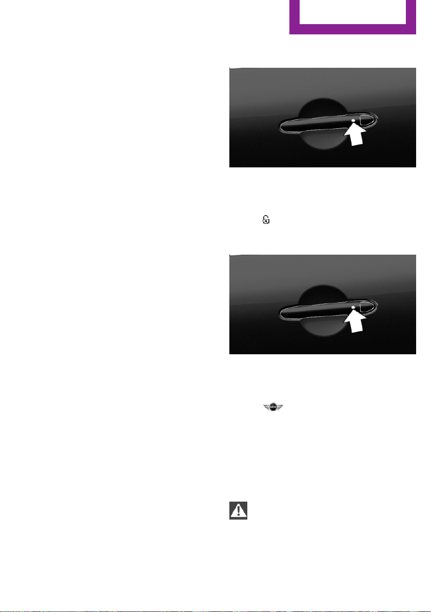
Opening and closing
CONTROLS
▷ Front doors: pull the door handle on the
door to open the door. The other doors re‐
main locked.
▷ Back doors: pull twice on the door handle
on the door to be opened; the first time un‐
locks the door, the second time opens it.
The other doors remain locked.
Comfort Access
Concept
The vehicle can be accessed without activating
the remote control.
All you need to do is to have the remote control
with you, such as in your pants pocket.
The vehicle automatically detects the remote
control when it is in close proximity or in the
vehicle's interior.
General information
To avoid locking it in the vehicle, do not place
the remote control in the cargo area.
Comfort Access supports the following func‐
tions:
▷ Unlocking and locking the vehicle.
▷ Convenient closing.
▷ Opening split doors.
▷ Open split doors with no-touch activation.
This function is not available in vehicles
with a trailer hitch.
Functional requirements
▷ To lock the vehicle, the remote control
must be located outside of the vehicle near
the doors.
▷ The next unlocking and locking cycle is not
possible until after approx. 2 seconds.
Unlocking
On the driver's or front passenger's door han‐
dle, press the button.
This corresponds to pressing the remote control
button:
Lock
On the driver's or front passenger's door han‐
dle, press the button.
This corresponds to pressing the remote control
button:
To save battery power, ensure that all power
consumers are turned off before locking the ve‐
hicle.
Convenient closing
Safety information
WARNING
With convenient closing, body parts can
be jammed. There is a risk of injury. Make sure
that the area of movement of the doors is clear
during convenient closing.◀
Online Edition for Part no. 01 40 2 976 545 - X/16
49
Page 50

CONTROLS
Opening and closing
Closing
Press and hold down the handle of the driver or
the front seat passenger.
This corresponds to pressing and holding the
remote control button:
In addition to locking, the windows and glass
sunroof will be closed.
Open split doors
General information
If the split doors are opened via Comfort Ac‐
cess, locked doors are not unlocked.
To avoid locking it into the vehicle, do not place
the remote control in the cargo area.
Safety information
WARNING
Body parts can be jammed when operat‐
ing the split doors. There is a risk of injury.
Make sure that the area of movement of the
split doors is clear during opening and clos‐
ing.◀
NOTE
The split doors swivel back and to the
side when they open. There is a risk of damage
to property. Make sure that the area of move‐
ment of the split doors is clear during opening
and closing.◀
NOTE
Sharp-edged or pointed objects can hit
the rear window and heat conductors while
driving. There is a risk of property damage.
Cover the edges and ensure that pointed ob‐
jects do not hit the rear window.◀
Opening
First press button in right-hand handle, ar‐
row 1, then press button in left-hand handle,
arrow 2.
Opening the split doors with no-touch
activation
Concept
The split doors can be opened with no-touch
activation using the remote control you are car‐
rying. Two sensors detect a forward-directed
foot motion in the center of the area at the rear
of the vehicle and the split doors open.
This function is not available in vehicles with
trailer hitch.
General information
To avoid locking it in the vehicle, do not place
the remote control in the cargo area.
If the remote control is in the sensor area, the
split doors can be opened or closed inadver‐
tently by an unconscious or alleged recognized
foot movement.
The sensor has an approximate range of
5 ft/1.50 m extending from the rear of the vehi‐
cle.
50
Online Edition for Part no. 01 40 2 976 545 - X/16
Page 51

Opening and closing
CONTROLS
If the split doors are opened with no-touch ac‐
tivation, locked doors are not unlocked.
Safety information
WARNING
During no-touch activation, vehicle parts
may be touched, e.g., hot exhaust system.
There is a risk of injury. When moving your foot,
make sure you have a firm stance and do not
touch the vehicle.◀
WARNING
Body parts can be jammed when operat‐
ing the split doors. There is a risk of injury.
Make sure that the area of movement of the
split doors is clear during opening and clos‐
ing.◀
NOTE
The split doors swivel back and to the
side when they open. There is a risk of damage
to property. Make sure that the area of move‐
ment of the split doors is clear during opening
and closing.◀
Performing the foot movement
Stand in the middle behind the vehicle at
1.
about an arm's length away from the rear
of the vehicle.
2. Wave a foot under the vehicle in the direc‐
tion of travel and immediately pull it back.
With this movement, the leg must pass
through the ranges of both sensors.
Opening
1. Perform the foot movement described ear‐
lier.
The right side of the split doors opens.
2. After complete opening of the right side,
make a second foot movement in order to
open the left side of the split doors.
Before the opening, the hazard warning system
flashes.
Malfunction
Remote control detection by the vehicle may
malfunction under the following circumstances:
▷ The battery of the remote control is dis‐
charged. Replace the battery, refer to
page 46.
▷ Interference of the radio connection from
transmission towers or other equipment
with high transmitting power.
▷ Shielding of the remote control due to
metal objects.
Do not transport the remote control to‐
gether with metal objects.
▷ Interference of the radio connection from
mobile phones or other electronic devices
in direct proximity to the remote control.
Do not transport the remote control to‐
gether with electronic devices.
In the case of a malfunction, unlock and lock
the vehicle using the buttons of the remote
control or using the integrated key, refer to
page 47.
Split Doors
General information
To avoid locking it in the vehicle, do not place
the remote control in the cargo area.
Depending on your vehicle's equipment and
the country version, it is possible to specify
whether the doors are also unlocked when un‐
Online Edition for Part no. 01 40 2 976 545 - X/16
51
Page 52

CONTROLS
Opening and closing
locking with the remote control. Adjusting the
settings, refer to page 55.
Safety information
WARNING
Body parts can be jammed when operat‐
ing the split doors. There is a risk of injury.
Make sure that the area of movement of the
split doors is clear during opening and clos‐
ing.◀
NOTE
The split doors swivel back and to the
side when they open. There is a risk of damage
to property. Make sure that the area of move‐
ment of the split doors is clear during opening
and closing.◀
NOTE
Sharp-edged or pointed objects can hit
the rear window and heat conductors while
driving. There is a risk of property damage.
Cover the edges and ensure that pointed ob‐
jects do not hit the rear window.◀
Opening from the outside
Depending on the setting, the doors may
also be unlocked. Unlocking with the re‐
mote control, refer to page 45.
The right side of the split doors opens.
Press and hold the button on the
remote control again for approx.
1 second.
The left side of the split doors opens.
Opening from the inside
With Steptronic transmission:
With the vehicle stationary, press the
button in the driver's floor area.
If the vehicle is locked, selector lever position P
must be engaged first.
With manual transmission:
With the vehicle stationary, press the
button in the driver's floor area twice in quick
succession.
The right split door opens. Press button again
to open the left split door as well.
Closing
To close the split doors, first press the left side,
then the right side.
▷ Without Comfort Access: unlock vehicle.
With Comfort Access: unlock the vehicle or
have the remote control with you.
Use the button in the handle to completely
open first the right side, arrow 1, and then
the left side of the split doors, arrow 2.
▷ Press and hold button on the re‐
mote control for approx. 1 second.
52
Online Edition for Part no. 01 40 2 976 545 - X/16
Driver profile
Concept
In the driver profiles, individual settings for sev‐
eral drivers can be stored and called up again
when required.
General information
There are three driver profiles with which per‐
sonal vehicle settings can be stored. Every re‐
mote control has one of these driver profiles
assigned.
If the vehicle is unlocked using a remote con‐
trol, the assigned personal driver profile will be
Page 53

Opening and closing
CONTROLS
activated. All settings stored in the driver profile
are automatically applied.
If several drivers use their own remote control,
the vehicle will adjust the personal settings dur‐
ing unlocking. These settings are also restored,
if the vehicle has been used in the meantime
by a person with a different remote control.
Changes to the settings are automatically saved
in the driver profile currently activated.
If another driver profile is selected via the on‐
board monitor, the settings saved in it will be
applied automatically. The new driver profile is
assigned to the remote control currently used.
There is an additional guest profile available
that is not assigned to any remote control: it
can be used to apply settings in the vehicle
without changing the personal driver profiles.
Functional requirements
For the system to be able to identify the driver
profile associated to a particular driver, the de‐
tected remote control must be clearly allocated
to the driver.
This is the case when:
▷ The driver is only carrying his or her own re‐
mote control.
▷ The driver unlocks the vehicle.
▷ The driver gets into the vehicle through the
driver's door.
Settings
The settings for the following systems and func‐
tions are saved in the active profile. The scope
of storable settings depends on country and
equipment.
▷ Unlocking and locking.
▷ Lights.
▷ Radio.
▷ Instrument cluster.
▷ Programmable memory buttons.
▷ Volumes, tone.
▷ Control Display.
▷ Climate control.
▷ Navigation.
▷ Park Distance Control PDC.
▷ Rearview camera.
▷ Head-up Display.
▷ MINI Driving Modes.
▷ Intelligent Safety.
Profile management
Selecting a driver profile
Regardless of the remote control in use, a dif‐
ferent driver profile may be activated. This al‐
lows you to call up personal vehicle settings if
you did not unlock the vehicle with your own
remote control.
Via the onboard monitor:
"My MINI"
1.
2. "Driver profiles"
3. Select driver profile.
4. "OK"
▷ All settings stored in the called-up driver
profile are automatically applied.
▷ The called-up driver profile is assigned to
the remote control being used at the time.
▷ If the driver profile is already assigned to a
different remote control, this driver profile
will apply to both remote controls.
Using a guest profile
The guest profile is for individual settings that
are stored in none of the three personal driver
profiles.
This can be useful for drivers who are using the
vehicle temporarily and do not have their own
driver profile.
Via the onboard monitor:
"My MINI"
1.
2. "Driver profiles"
Online Edition for Part no. 01 40 2 976 545 - X/16
53
Page 54

CONTROLS
Opening and closing
3. "Drive off (guest)"
4. "OK"
The guest profile cannot be renamed. It is not
assigned to the current remote control.
Renaming a driver profile
A personal name can be assigned to the active
driver profile to avoid confusion between the
driver profiles.
Via the onboard monitor:
1. "My MINI"
2. "Driver profiles"
3. Select driver profile.
The driver profile marked with this sym‐
bol can be renamed.
4. "Change driver profile name"
5. Enter profile name.
6. Select the symbol.
Resetting a driver profile
The settings of the active driver profile are reset
to their factory settings.
Via the onboard monitor:
"My MINI"
1.
2. "Driver profiles"
The driver profile marked with this sym‐
bol can be reset.
3. Select driver profile.
4. "Reset driver profile"
5. "OK"
Exporting driver profiles
Most settings of the active driver profile can be
exported.
This can be helpful for saving and retrieving
personal settings, for instance before delivering
the vehicle to a workshop. The saved driver
profiles can be taken into another vehicle.
Export is made via the USB port to a USB stor‐
age device.
Popular file systems for USB media are sup‐
ported. FAT32 and exFAT are the recom‐
mended formats for profile export. Other for‐
mats may not support the export.
Via the onboard monitor:
1. "My MINI"
2. "Driver profiles"
3. Select driver profile.
The driver profile marked with this sym‐
bol can be exported.
4. "Export driver profile (USB)"
Select USB storage device as needed.
Importing driver profiles
Profiles stored on a USB storage device can be
imported via the USB interface.
The existing settings of the active driver profile
are overwritten with the settings of the im‐
ported driver profile.
Via the onboard monitor:
"My MINI"
1.
2. "Driver profiles"
3. Select the driver profile to be overwritten.
The driver profile marked with this sym‐
bol can be overwritten.
4. "Import driver profile (USB)"
Select USB storage device as needed.
5. Select the driver profile to be imported.
Displaying driver profiles during start
The driver profiles can be displayed during each
start to select the desired profile.
Via the onboard monitor:
"My MINI"
1.
2. "Driver profiles"
3. "Show driver profiles at startup"
54
Online Edition for Part no. 01 40 2 976 545 - X/16
Page 55

Opening and closing
CONTROLS
System limits
A clear assignment between the remote control
and driver may not be possible in the following
cases, for example.
▷ The passenger unlocks the vehicle with his
or her own remote control, but another
person is driving.
▷ The driver unlocks the vehicle via Comfort
Access and has multiple remote controls
with him or her.
▷ The driver changes, but the vehicle is not
locked and unlocked.
▷ Multiple remote controls are located out‐
side of the vehicle.
Settings
General information
Depending on your vehicle's equipment and
the country version, various settings for open‐
ing and closing are possible.
These settings are stored for the driver profile,
refer to page 52, currently used.
Unlocking
Doors
Via the onboard monitor:
"My MINI"
1.
2. "Vehicle settings"
3. "Doors/Key"
4. "Driver's door" or "All doors"
5. Select desired setting:
▷ "Driver's door only"
Only the driver's door and the fuel filler
flap are unlocked. Pressing again un‐
locks the entire vehicle.
▷ "All doors"
The entire vehicle is unlocked.
Split doors
Via the onboard monitor:
1. "My MINI"
2. "Vehicle settings"
3. "Doors/Key"
4. "Split Rear Doors" or "Split Rear Doors and
door(s)"
5. Select desired setting:
▷ "Split Rear Doors"
Only the split doors are opened.
▷ "Split Rear Doors and door(s)"
The split doors are opened and the
doors unlocked.
Depending on optional features and country
version, this setting is not offered in some
cases.
Automatic locking
Via the onboard monitor:
"My MINI"
1.
2. "Vehicle settings"
3. "Doors/Key"
4. Select desired setting:
▷ "Lock automatically"
The vehicle locks automatically after a
short period of time if no door is
opened after unlocking.
▷ "Lock after starting to drive"
The vehicle locks automatically after
you drive off.
Automatic unlocking
Via the onboard monitor:
"My MINI"
1.
2. "Vehicle settings"
3. "Doors/Key"
4. "Unlock at end of trip"
Online Edition for Part no. 01 40 2 976 545 - X/16
55
Page 56

CONTROLS
Opening and closing
After the engine is switched off by pressing
the Start/Stop button, the locked vehicle is
automatically unlocked.
Confirmation signals from the vehicle
Via the onboard monitor:
1. "My MINI"
2. "Vehicle settings"
3. "Doors/Key"
4. Deactivate or activate the desired confir‐
mation signals.
▷ "Flash for lock/unlock"
Unlocking is signaled by two flashes,
locking by one.
▷ With alarm system:
"Acoustic signal for lock/unlock"
Unlocking is signaled by one honk of
the horn.
Adjusting the last seat and mirror
position
When the vehicle is unlocked, the driver's seat
and exterior mirrors resume their last set posi‐
tions.
Via the onboard monitor:
"My MINI"
1.
2. "Driver profiles"
3. Select driver profile.
The setting can be made for the driver
profile marked with this symbol.
4. "Last seat position automatic"
▷ Movements in the vehicle interior.
▷ Changes in the vehicle tilt, e. g., during at‐
tempts at stealing a wheel or when towing
the vehicle.
▷ Disconnected battery voltage.
▷ Improper use of the socket for Onboard Di‐
agnosis.
The alarm system signals these changes visually
and acoustically:
▷ By acoustic alarm.
▷ By switching on the hazard warning system.
▷ By flashing the daytime running lights.
Overview
Indicator light in the roof fin.
Alarm system
General information
When the vehicle is locked, the vehicle alarm
system reacts to the following changes:
▷ Unauthorized opening of a door, the hood
or the split doors.
56
Online Edition for Part no. 01 40 2 976 545 - X/16
Indicator light on the interior mirror.
Switching on and off
When you lock or unlock the vehicle, either
with the remote control or with Comfort Access,
the alarm system is switched on and off at the
same time.
Page 57

Opening and closing
CONTROLS
Opening the doors with the alarm
system switched on
The alarm system is triggered when a door is
opened if the door was unlocked using the in‐
tegrated key in the door lock.
Switching off the alarm, refer to page 58.
Opening the split doors with the alarm
system switched on
The split doors can be opened even when the
alarm system is switched on.
After the split doors are closed, they are locked
and monitored again when the doors are
locked. The hazard warning system flashes
once.
Panic mode
You can trigger the alarm system if you find
yourself in a dangerous situation.
Press button on the remote control for
at least 3 seconds.
To switch off the alarm: press any button.
Signals of the indicator lights
▷ The indicator light flashes briefly every
2 seconds:
The alarm system is switched on.
▷ Indicator light flashes for approx. 10 sec‐
onds, then it flashes briefly every 2 sec‐
onds:
Interior motion sensor and tilt alarm sensor
are not active, as doors, hood, or split doors
are not correctly closed. Correctly closed
access points are secured.
When the still open access points are
closed, interior motion sensor and tilt alarm
sensor will be switched on.
▷ The indicator light goes out after unlocking:
The vehicle has not been tampered with.
▷ The indicator light flashes after unlocking
until the engine ignition is switched on, but
no longer than approx. 5 minutes:
An alarm has been triggered.
Tilt alarm sensor
The tilt of the vehicle is monitored.
The alarm system responds in situations such as
attempts to steal a wheel or when the vehicle is
towed.
Interior motion sensor
The windows and the glass sunroof must be
closed for the system to function properly.
Avoiding unintentional alarms
General information
The tilt alarm sensor and interior motion sensor
may trigger the alarm even though no one is
trying to gain unauthorized access.
Possible situations for an unintended alarm:
▷ In automatic vehicle washes.
▷ In duplex garages.
▷ During transport on trains carrying vehicles,
at sea or on a trailer.
▷ With animals in the vehicle.
For such situations, the tilt alarm sensor and in‐
terior motion sensor can be switched off.
Switching off the tilt alarm sensor and
interior motion sensor
Press the remote control button again
within 10 seconds as soon as the vehi‐
cle is locked.
The indicator lamp lights up for approx. 2 sec‐
onds and then continues to flash.
The tilt alarm sensor and interior motion sensor
are turned off until the vehicle is locked again.
Online Edition for Part no. 01 40 2 976 545 - X/16
57
Page 58

CONTROLS
Opening and closing
Switching off the alarm
▷ Unlock the vehicle with the remote control
or switch on the ignition, if needed through
emergency detection of remote control, re‐
fer to page 47.
▷ With Comfort Access: If you have the re‐
mote control with you, unlock the vehicle
using the button on the driver's side or pas‐
senger side door.
Power windows
General information
If an accident of a certain severity occurs, the
windows are automatically closed except a
gap.
Safety information
WARNING
When operating the windows, body parts
and objects can be jammed. There is a risk of
injury or risk of property damage. Make sure
that the area of movement of the windows is
clear during opening and closing.◀
WARNING
Unattended children or animals can
cause the vehicle to move and endanger them‐
selves and traffic, e.g., due to the following ac‐
tions:
▷ Pressing the Start/Stop button.
▷ Releasing the parking brake.
▷ Opening and closing the doors or windows.
▷ Engaging selector lever position N.
▷ Using vehicle equipment.
There is a risk of accidents or injuries. Do not
leave children or animals unattended in the ve‐
hicle. Take the remote control with you when
exiting and lock the vehicle.◀
Overview
Opening
▷
▷
Convenient opening via the remote control, re‐
fer to page 45.
Press the button to the resistance
point.
The window opens while the switch is being
held.
Press the switch beyond the resist‐
ance point.
The window opens automatically. Pressing
the switch again stops the motion.
Closing
▷
▷
Closing by means of Comfort Access, refer to
page 49.
Pull the switch to the resistance point.
The window closes while the switch is being
held.
Pull the switch beyond the resistance
point.
The window closes automatically if the door
is closed. Pulling the switch again stops the
motion.
58
Online Edition for Part no. 01 40 2 976 545 - X/16
Page 59

Opening and closing
CONTROLS
Pinch protection system
General information
If closing force exceeds a specific threshold as a
window closes, closing is interrupted.
The window opens slightly.
Safety information
WARNING
Accessories on the windows such as an‐
tennas can impact jam protection. There is a
risk of injury. Do not install accessories in the
area of movement of the windows.◀
Closing without the jam protection
system
In case of danger from the outside or if ice
might prevent normal closing, proceed as fol‐
lows:
1. Pull the switch past the resistance
point and hold it there.
The window closes with limited jam protec‐
tion . If the closing force exceeds a specific
threshold, closing is interrupted.
2.
Pull the switch past the resistance
point again within approx. 4 seconds and
hold it there.
The window closes without jam protection .
Safety switch
General information
The opening and closing of the rear window
can be blocked via the safety switch for the
rear. This makes sense, e.g., if children or ani‐
mals are carried in the rear.
If an accident of a certain severity occurs, the
safety function is switched off automatically.
Overview
Switching on and off
Press button.
The LED lights up if the safety function
is switched on.
Malfunction
General information
In certain situations a window can only be op‐
erated to a limited extent.
▷ After a power failure during the opening or
closing process, the a window can only be
operated to a limited extent. The system
must be initialized in this case.
▷ The power window motors are equipped
with overheating protection. If a window is
opened and closed several times within a
short period of time, the overheating pro‐
tection switches the motor off temporarily.
Depending on the degree of overheating, it
may only be possible to close the window
or it may not be possible to operate it at all.
In this case: allow the power window motor
to cool down.
Initializing the system
The system can be initialized when the vehicle
is stationary and the engine is running.
During initialization, the affected window
closes without jam protection .
Online Edition for Part no. 01 40 2 976 545 - X/16
59
Page 60

CONTROLS
Opening and closing
WARNING
When operating the windows, body parts
and objects can be jammed. There is a risk of
injury or risk of property damage. Make sure
that the area of movement of the windows is
clear during opening and closing.◀
1. Open the affected window completely.
2.
3.
4. Release switch.
Pull the switch to the resistance point
and hold.
The window closes.
Continue holding the switch pulled to
the resistance point.
Depending on the equipment, the window
opens and closes one or twice after approx.
15 seconds.
Panoramic glass sun‐
roof
General information
If an accident of a certain severity occurs, the
glass sunroof and possibly the electrical sliding
visor close automatically.
Safety information
WARNING
Body parts can be jammed when operat‐
ing the glass sunroof. There is a risk of injury.
Make sure that the area of movement of the
glass sunroof is clear during opening and clos‐
ing.◀
WARNING
Unattended children or animals can
cause the vehicle to move and endanger them‐
selves and traffic, e.g., due to the following ac‐
tions:
▷ Pressing the Start/Stop button.
▷ Releasing the parking brake.
▷ Opening and closing the doors or windows.
▷ Engaging selector lever position N.
▷ Using vehicle equipment.
There is a risk of accidents or injuries. Do not
leave children or animals unattended in the ve‐
hicle. Take the remote control with you when
exiting and lock the vehicle.◀
Overview
Tilting the glass sunroof
Press back the switch up to or
beyond the resistance point and
release it.
The glass sunroof is raised.
Opening glass sunroof
When the glass sunroof is closed
Press the switch back beyond
the resistance point and release
it twice.
The glass sunroof is opened.
Pressing the switch again stops
the motion.
60
Online Edition for Part no. 01 40 2 976 545 - X/16
Page 61

Opening and closing
CONTROLS
With the glass sunroof completely
raised
▷ Slide switch back to the re‐
sistance point and hold.
The glass sunroof is opened
as long as the switch is
pressed.
▷ Press the switch back beyond the resist‐
ance point and release it.
The glass sunroof is opened.
Pressing the switch again stops the motion.
Comfort position
If the glass sunroof stops before it is completely
opened, it is in the Comfort position. In this po‐
sition the wind noises in the interior are the
least.
If desired, continue the movement by Pressing
the switch.
Closing glass sunroof
With the glass sunroof open
▷ Slide switch forward to the
resistance point and hold.
The glass sunroof is closed as
long as the switch is pressed
and stops in the raised posi‐
tion.
▷ Press the switch forward beyond the resist‐
ance point and release it.
The glass sunroof is closed and stops in the
raised position.
Pressing the switch toward the back stops
the motion.
▷ Press the switch forward beyond the resist‐
ance point and release it twice.
The glass sunroof is closed.
Pressing the switch again stops the motion.
With the glass sunroof completely
raised
Press the switch forward beyond
the resistance point and release
it.
The glass sunroof is closed.
Pinch protection system
General information
If the closing force exceeds a specific value as a
glass sunroof closes, the closing action is inter‐
rupted.
The glass sunroof opens slightly.
Closing without the jam protection
system
If there is an external danger, proceed as fol‐
lows:
Push the switch forward past the resistance
1.
point and hold it.
The glass sunroof closes with limited jam
protection. If the closing force exceeds a
specific threshold, closing is interrupted.
2. Push the switch forward again past the re‐
sistance point and hold until the glass sun‐
roof closes without jam protection . Make
sure that the closing area is clear.
Initializing after a power interruption
After a power failure during the opening or
closing process, the glass sunroof can only be
operated to a limited extent. The system must
be initialized in this case. MINI recommends
having this work performed only by a dealer's
service center or another qualified service cen‐
ter or repair shop.
Online Edition for Part no. 01 40 2 976 545 - X/16
61
Page 62

CONTROLS
Settings
Settings
Vehicle features and op‐
tions
This chapter describes all standard, countryspecific and optional features offered with the
series. It also describes features that are not
necessarily available in your vehicle, e. g., due
to the selected options or country versions. This
also applies to safety-related functions and sys‐
tems. When using these functions and systems,
the applicable laws and regulations must be
observed.
Sitting safely
An ideal seating position that meets the needs
of the occupants can make a vital contribution
to relaxed, fatigue-free driving.
In the event of an accident, the correct seating
position plays an important role. Additionally,
observe the following chapters for safe driving:
▷ Safety belts, refer to page 65.
▷ Head restraints, refer to page 66.
▷ Airbags, refer to page 118.
WARNING
With a backrest inclined too far to the
rear, the protective effect of the safety belt
cannot be ensured anymore. There is a risk of
sliding under the safety belt in an accident.
There is a risk of injuries or danger to life. Ad‐
just the seat prior to starting the trip. Adjust the
backrest so that it is in the most upright posi‐
tion as possible and do not adjust again while
driving.◀
WARNING
There is a risk of jamming when moving
the seats. There is a risk of injury or risk of
property damage. Make sure that the area of
movement of the seat is clear prior to any ad‐
justment.◀
Manually adjustable seats
Overview
Front seats
Safety information
WARNING
Seat adjustments while driving can lead
to unexpected movements of the seat. Vehicle
control could be lost. There is a risk of an acci‐
dent. Only adjust the seat on the driver's side
when the vehicle is stationary.◀
62
Online Edition for Part no. 01 40 2 976 545 - X/16
1 Forward/backward
2 Thigh support
3 Height
4 Backrest tilt
Page 63

Settings
CONTROLS
Forward/backward
Pull the lever and slide the seat in the desired
direction.
After releasing the lever, move the seat forward
or back slightly making sure it engages prop‐
erly.
Height
Lumbar support
The curvature of the seat backrest can be ad‐
justed in a way that it supports the lumbar re‐
gion of the spine. The lower back and the spine
are supported for upright posture.
Turn the wheel in order to increase or decrease
the curvature.
Electrically adjustable seats
General information
The seat setting for the driver's seat is stored
for the profile currently used. When the vehicle
is unlocked via the remote control, the position
is automatically retrieved if the function, refer
to page 56, is activated for this purpose.
Pull the lever up or press it down as often as
needed to reach the desired height.
Backrest tilt
Pull the lever and apply your weight to the
backrest or lift it off, as necessary.
Online Edition for Part no. 01 40 2 976 545 - X/16
Overview
1 Seat and mirror memory
2 Lumbar support
3 Backrest tilt
4 Forward/backward, height, seat tilt
63
Page 64

CONTROLS
Settings
Forward/backward
Push switch forward or backward.
Height
Push switch up or down.
Seat tilt
Backrest tilt
Move switch forward or backward.
Lumbar support
Concept
The curvature of the seat backrest can be ad‐
justed in a way that it supports the lumbar re‐
gion of the spine. The lower back and the spine
are supported for upright posture.
Settings
▷ Press the front/rear section
of the switch:
The curvature is increased/
decreased.
▷ Press the upper/lower sec‐
tion of the switch:
The curvature is shifted up/
down.
Move switch up or down.
64
Thigh support
Pull the lever at the front of the seat and adjust
the thigh support.
Online Edition for Part no. 01 40 2 976 545 - X/16
Page 65

Settings
CONTROLS
Front seat heating
Overview
Seat heating
Switching on
Press button once for each tempera‐
ture level.
The maximum temperature is reached when
three LEDs are lit.
If the trip is continued within approx. 15 mi‐
nutes after a stop, seat heating is activated au‐
tomatically with the temperature selected last.
When GREEN Mode, refer to page 189, is acti‐
vated, the heater output is reduced.
Switching off
Press and hold the button, until the
LEDs go out.
Safety belts
Number of safety belts
The vehicle is fitted with five safety belts to en‐
sure occupant safety. However, they can only
offer protection when adjusted correctly.
The two outer safety belt buckles of the rear
seat are intended for the persons sitting on the
left and right.
The center safety belt buckle of the rear seat is
intended for the person sitting in the middle.
General information
Always make sure that safety belts are being
worn by all occupants before driving off. Al‐
though airbags enhance safety by providing
added protection, they are not a substitute for
safety belts.
Slowly guide the safety belt out of the holder
when fastening it.
The upper shoulder strap's anchorage point will
be correct for adult seat occupants of every
build if the seat is correctly adjusted.
Safety information
WARNING
If the safety belt is used to buckle more
than one person, the protective effect of the
safety belt can no longer be ensured. There is a
risk of injuries or danger to life. Do not allow
more than one person to wear a single safety
belt. Infants and children are not allowed on an
occupant's lap, but must be transported and
secured in designated child restraint systems.◀
WARNING
The protective effect of the safety belts
can be limited or lost when safety belts are fas‐
tened incorrectly. An incorrectly fastened safety
belt can cause additional injuries, e.g., in the
event of an accident or during braking and eva‐
sive maneuvers. There is a risk of injuries or
danger to life. Make sure that all occupants are
wearing safety belts correctly.◀
WARNING
With a rear backrest that is not locked,
the protective function of the middle safety belt
is not guaranteed. There is a risk of injuries or
danger to life. If you are using the middle safety
belt, lock the wider rear backrest.◀
Online Edition for Part no. 01 40 2 976 545 - X/16
65
Page 66

CONTROLS
Settings
WARNING
The protective effect of the safety belts
may not be fully functional or fail in the follow‐
ing situations:
▷ Safety belts are damaged, soiled or
changed in any other way.
▷ Safety belt buckle is damaged or heavily
soiled.
▷ Belt tensioners or belt retractors were
modified.
Safety belts can be imperceptibly damaged in
the event of an accident. There is a risk of inju‐
ries or danger to life. Do not modify safety
belts, safety belt buckles, belt tensioners, belt
retractors or belt anchors and keep them clean.
Have the safety belts checked after an accident
at the dealer’s service center or another quali‐
fied service center or repair shop.◀
Correct use of safety belts
▷ Wear the safety belt twist-free and as tight
to your body as possible over your lap and
shoulders.
▷ Wear the safety belt deep on your hips over
your lap. The safety belt may not press on
your stomach.
▷ Do not rub the safety belt against sharp
edges, or guide it or jam it in across hard or
fragile objects.
▷ Avoid thick clothing.
▷ Re-tighten the safety belt frequently up‐
ward around your upper body.
Buckling the seat belt
Make sure you hear the latch plate engage in
the belt buckle.
Unbuckling the safety belt
Hold the safety belt firmly.
1.
2. Press the red button in the belt buckle.
3. Guide the safety belt back into its roll-up
mechanism.
Safety belt reminder for driver's seat
and front passenger seat
The indicator lamp lights up and a sig‐
nal sounds. Make sure that the safety
belts are positioned correctly. The
safety belt reminder is active at speeds above
approx. 6 mph/10 km/h. It can also be acti‐
vated if objects are placed on the front passen‐
ger seat.
Front head restraints
Correctly adjusted head restraint
66
General information
A correctly adjusted head restraint reduces the
risk of injury to cervical vertebrae in the event
of an accident.
Height
Adjust the head restraint so that its center is
approximately at eye level.
Online Edition for Part no. 01 40 2 976 545 - X/16
Page 67

Settings
CONTROLS
Distance
Adjust the distance so that the head restraint is
as close as possible to the back of the head.
Adjust the head restraint via the backrest tilt as
needed.
Safety information
WARNING
A missing protective effect due to re‐
moved or not correctly adjusted head restraints
can cause injuries in the head and neck area.
There is a risk of injury. Before driving, install
the head restraints on the occupied seats. En‐
sure that the middle of the head restraint sup‐
ports the back of the head approximately at
eye level.◀
WARNING
Body parts can be jammed when moving
the head restraint. There is a risk of injury.
Make sure that the area of movement is clear
when moving the head restraint.◀
WARNING
Objects on the head restraint reduce the
protective effect in the head and neck area.
There is a risk of injury.
▷ Do not use seat or head restraint covers.
▷ Do not hang objects, e.g., clothes hangers,
directly on the head restraint.
▷ Only use accessories that have been deter‐
mined to be safe for attachment to a head
restraint.
▷ Do not use any accessories, e.g., pillows,
while driving.◀
To adjust the height: basic seat
▷ To lower: press the button, arrow 1, and
push the head restraint down.
▷ To raise: push the head restraint up.
Removing: John Cooper Works sport
seat
The head restraints cannot be removed.
To remove: basic seat
Only remove the head restraint if no one will be
sitting in the seat in question.
Fold the seat backrest forward if needed.
1.
2. Pull head restraint up as far as possible.
3. Press the button, arrow 1, and pull the
head restraint out completely.
Adjusting the height: John Cooper
Works sport seat
The height of the head restraints cannot be ad‐
justed.
Online Edition for Part no. 01 40 2 976 545 - X/16
67
Page 68
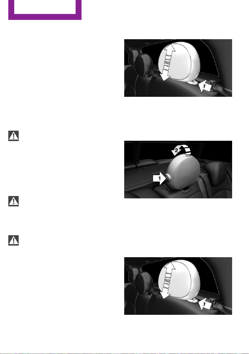
CONTROLS
Settings
Rear head restraints
Correctly adjusted head restraint
General information
A correctly adjusted head restraint reduces the
risk of injury to cervical vertebrae in the event
of an accident.
Height
Adjust the head restraint so that its center is
approximately at eye level.
Safety information
WARNING
A missing protective effect due to re‐
moved or not correctly adjusted head restraints
can cause injuries in the head and neck area.
There is a risk of injury. Before driving, install
the head restraints on the occupied seats. En‐
sure that the middle of the head restraint sup‐
ports the back of the head approximately at
eye level.◀
WARNING
Body parts can be jammed when moving
the head restraint. There is a risk of injury.
Make sure that the area of movement is clear
when moving the head restraint.◀
WARNING
Objects on the head restraint reduce the
protective effect in the head and neck area.
There is a risk of injury.
▷ Do not use seat or head restraint covers.
▷ Do not hang objects, e.g., clothes hangers,
directly on the head restraint.
▷ Only use accessories that have been deter‐
mined to be safe for attachment to a head
restraint.
▷ Do not use any accessories, e.g., pillows,
while driving.◀
Adjusting the height
▷ To lower: press the button, arrow 1, and
push the head restraint down.
▷ To raise: push the head restraint up.
Fold down
▷ To fold down: press the button, arrow 1,
and press down the head restraint, arrow 2.
▷ To fold up: pull up head restraints.
Removing
Only remove the head restraint if no one will be
sitting in the seat in question.
Fold down the rear seat backrest, refer to
1.
page 178, in question.
68
Online Edition for Part no. 01 40 2 976 545 - X/16
Page 69

Settings
CONTROLS
2. Pull head restraint up against the resist‐
ance.
3. Press the button, arrow 1, and pull the
head restraint out completely.
Seat and mirror memory
Concept
Two different driver's seat and exterior mirror
positions can be stored per driver profile, refer
to page 52, and retrieved.
General information
The adjustment of the lumbar support is not
stored.
Safety information
WARNING
There is a risk of jamming when moving
the seats. There is a risk of injury or risk of
property damage. Make sure that the area of
movement of the seat is clear prior to any ad‐
justment.◀
WARNING
Using the memory function while driving
can lead to unexpected movements of the seat.
Vehicle control could be lost. There is a risk of
an accident. Only retrieve the memory function
when the vehicle is stationary.◀
Storing
1. Switch on the ignition.
2. Set the desired position.
3.
4. Press selected button 1 or 2 while the LED
Press button. The LED in the button
lights up.
is lit. The LED goes out.
Calling up settings
The stored position is called up automatically.
Press selected button 1 or 2.
The procedure stops when a switch for setting
the seat or one of the memory buttons is
pressed.
While driving, the seat position adjustment on
the driver's side is interrupted after a short
time.
Calling up of a seat position
deactivated
After a brief period, calling up stored seat posi‐
tions is deactivated to save battery power.
To reactivate calling up of a seat position:
▷ Open or close the door or split doors.
▷ Press a button on the remote control.
▷ Press the Start/Stop button.
Mirrors
Overview
Exterior mirrors
General information
The mirror on the passenger side is more
curved than the driver's side mirror.
The mirror setting is stored for the driver profile
currently in use. When the vehicle is unlocked
via the remote control, the position is automat‐
ically retrieved if the function, refer to page 56,
is activated for this purpose.
Online Edition for Part no. 01 40 2 976 545 - X/16
69
Page 70

CONTROLS
Settings
Safety information
WARNING
Objects reflected in the mirror are closer
than they appear. The distance to the traffic
behind could be incorrectly estimated, e.g.,
while changing lanes. There is a risk of an acci‐
dent. Estimate the distance to the traffic behind
by looking over your shoulder.◀
Overview
1 Settings 70
2 Left/right, Automatic Curb Monitor
3 Folding in and out 70
Selecting a mirror
To change over to the other mirror:
Slide the switch.
Adjusting electrically
Press button.
The mirror moves in accordance with
the button movement.
Saving positions
The current exterior mirror position can be
stored via the seat and mirror memory, refer to
page 69.
Adjusting manually
In case of an electrical malfunction, press the
edges of the mirror.
Folding in and out
NOTE
Depending on the vehicle width, the ve‐
hicle can be damaged in vehicle washes. There
is a risk of property damage. Before washing,
fold in the mirrors by hand or with the button.◀
Press button.
Possible at speeds up to approx.
15 mph/20 km/h.
Fold the mirrors in and out is advantageous in
the following situations:
▷ In vehicle washes.
▷ On narrow roads.
▷ For folding mirrors back out that were
folded away manually.
Mirrors that were folded in are folded out auto‐
matically at a speed of approx.
25 mph/40 km/h.
Automatic heating
Both exterior mirrors are automatically heated
whenever the engine is running.
Automatic dimming feature
The exterior mirror on the driver's side is auto‐
matically dimmed. Photocells in the interior
mirror, refer to page 71, are used to control
this.
Automatic Curb Monitor, exterior mirror
The concept
If reverse gear is engaged, the mirror glass on
the front passenger side is tilted downward.
This improves your view of the curb and other
low-lying obstacles when parking, for example.
Activating
1. Slide the switch to the driver's side
mirror position.
70
Online Edition for Part no. 01 40 2 976 545 - X/16
Page 71

Settings
CONTROLS
2. Engage selector lever position R.
Deactivating
Slide the switch to the passenger side mirror
position.
Interior mirror, manually dimmable
Flip lever
To reduce the blinding effect of the interior rear
view mirror, flip the lever forward.
Turn knob
Interior mirror, automatic dimming
feature
Overview
Photocells are used for control:
▷ In the mirror glass.
▷ On the back of the mirror.
Functional requirements
▷ Keep the photocells clean.
▷ Do not cover the area between the inside
rearview mirror and the windshield.
Steering wheel
Turn the knob to reduce the blinding effect by
the interior mirror.
Online Edition for Part no. 01 40 2 976 545 - X/16
Safety information
WARNING
Steering wheel adjustments while driving
can lead to unexpected steering wheel move‐
ments. Vehicle control could be lost. There is a
risk of an accident. Adjust the steering wheel
while the vehicle is stationary only.◀
71
Page 72

CONTROLS
Settings
Adjusting
1. Switch on the ignition.
2. Fold the lever down.
3. Move the steering wheel to the preferred
height and angle to suit your seating posi‐
tion.
4. Fold the lever back.
5. Switch off the ignition again if needed.
72
Online Edition for Part no. 01 40 2 976 545 - X/16
Page 73

Transporting children safely
Transporting children safely
CONTROLS
Vehicle features and op‐
tions
This chapter describes all standard, countryspecific and optional features offered with the
series. It also describes features that are not
The right place for children
Safety information
WARNING
Unattended children or animals can
cause the vehicle to move and endanger them‐
selves and traffic, e.g., due to the following ac‐
tions:
▷ Pressing the Start/Stop button.
▷ Releasing the parking brake.
▷ Opening and closing the doors or windows.
▷ Engaging selector lever position N.
▷ Using vehicle equipment.
There is a risk of accidents or injuries. Do not
leave children or animals unattended in the ve‐
hicle. Take the remote control with you when
exiting and lock the vehicle.◀
necessarily available in your vehicle, e. g., due
to the selected options or country versions. This
also applies to safety-related functions and sys‐
tems. When using these functions and systems,
the applicable laws and regulations must be
observed.
system can no longer be used due to their age,
weight and size.
Safety information
WARNING
The safety belt cannot be fastened cor‐
rectly on children shorter than 5 ft, 150 cm
without suitable additional child restraint sys‐
tems. The protective effect of the safety belts
can be limited or lost when safety belts are fas‐
tened incorrectly. An incorrectly fastened safety
belt can cause additional injuries, for instance
in the event of an accident or during braking
and evasive maneuvers. There is a risk of inju‐
ries or danger to life. Secure children shorter
than 5 ft, 150 cm using suitable child restraint
systems.◀
Always transport children in the rear
seat
General information
Accident research shows that the safest place
for children is in the rear seat.
Transport children younger than 13 years of
age or shorter than 5 ft/150 cm only in the rear
seat in suitable child restraint systems designed
for the age, weight and size of the child. Chil‐
dren 13 years of age or older must wear a
safety belt as soon as a suitable child restraint
Online Edition for Part no. 01 40 2 976 545 - X/16
Children on the front passenger seat
General information
Before using a child restraint system on the
front passenger seat, ensure that the front,
knee, and side airbags on the front passenger
side are deactivated. Automatic deactivation of
front-seat passenger airbags, refer to
page 120.
73
Page 74

CONTROLS
Transporting children safely
Safety information
WARNING
Active front-seat passenger airbags can
injure a child in a child restraint system when
the airbags are activated. There is a risk of in‐
jury. Make sure that the front-seat passenger
airbags are deactivated and that the PASSEN‐
GER AIRBAG OFF indicator lamp lights up.◀
WARNING
The stability of the child restraint system
is limited or compromised with incorrect seat
adjustment or improper installation of the child
seat. There is a risk of injuries or danger to life.
Make sure that the child restraint system fits
securely against the backrest. If possible, adjust
the backrest tilt for all affected backrests and
correctly adjust the seats. Make sure that seats
and backrests are securely engaged. If possible,
adjust the height of the head restraints or re‐
move them.◀
Installing child re‐
straint systems
General information
Pay attention to the specifications of the child
restraint system manufacturer when selecting,
installing, and using child restraint systems.
In order to faciliate the installation of a backfacing child restraint system in the rear:
Move the front passenger's seat as far up as
possible before folding down the backrest.
the backrest tilt for all affected backrests and
correctly adjust the seats. Make sure that seats
and backrests are securely engaged. If possible,
adjust the height of the head restraints or re‐
move them.◀
On the front passenger seat
Deactivating airbags
WARNING
Active front-seat passenger airbags can
injure a child in a child restraint system when
the airbags are activated. There is a risk of in‐
jury. Make sure that the front-seat passenger
airbags are deactivated and that the PASSEN‐
GER AIRBAG OFF indicator lamp lights up.◀
After installing a child restraint system in the
front passenger seat, make sure that the front,
knee and side airbags on the front passenger
side are deactivated.
Deactivate the front-seat passenger airbags au‐
tomatically, refer to page 120.
Seat position and height
Before installing a child restraint system, move
the front passenger seat as far back as possible
and adjust its height to the highest and thus
best possible position for the belt and to offer
optimal protection in the event of an accident.
If the upper anchorage of the safety belt is lo‐
cated in front of the belt guide of the child seat,
move the passenger seat carefully forward until
the best possible belt guide position is reached.
Safety information
WARNING
The stability of the child restraint system
is limited or compromised with incorrect seat
adjustment or improper installation of the child
seat. There is a risk of injuries or danger to life.
Make sure that the child restraint system fits
securely against the backrest. If possible, adjust
74
Online Edition for Part no. 01 40 2 976 545 - X/16
Page 75

Transporting children safely
CONTROLS
Child seat security
Locking the safety belt
1. Pull out the belt strap completely.
2. Secure the child restraint system with the
belt.
3. Allow the belt strap to be pulled in and pull
it tight against the child restraint system.
The safety belt is locked.
Unlocking the safety belt
The rear safety belts and the front passenger
safety belt can be permanently locked to fasten
child restraint systems.
1. Unbuckle the safety belt buckle.
2. Remove the child restraint system.
3. Allow the belt strap to be pulled in com‐
pletely.
LATCH child restraint fixing system
General information
LATCH: Lower Anchors and Tether for Children.
Pay attention to the operating and safety infor‐
mation of the child restraint system manufac‐
turer when installing and using LATCH child re‐
straint fixing systems.
Mounts for the lower LATCH anchors
The lower anchors may be used to attach the
CRS to the vehicle seat up to a combined child
and CRS weight of 65 lb/30 kg when the child is
restrained by the internal harnesses.
Safety information
WARNING
If the LATCH child restraint fixing systems
are not correctly engaged, the protective effect
of the LATCH child restraint fixing system can
be limited. There is a risk of injuries or danger
to life. Make sure that the lower anchors are se‐
curely engaged and that the LATCH child re‐
straint fixing system fits securely against the
backrest.◀
Position
The corresponding symbol shows the
mounts for the lower LATCH anchors.
Seats equipped with lower anchors are
marked with a pair, 2, of LATCH sym‐
bols. It is not recommended to use the
inner lower anchors of standard outer
LATCH positions to fasten a child restraint sys‐
tem on the middle seat. Use the vehicle seat
belt instead for the middle seat.
Before installing LATCH child restraint
fixing systems
Pull the belt away from the area of the child re‐
straint system.
Assembly of LATCH child restraint
systems
Install child restraint system, see manufac‐
1.
turer's information.
2. Ensure that both LATCH anchors are prop‐
erly connected.
Online Edition for Part no. 01 40 2 976 545 - X/16
75
Page 76

CONTROLS
Transporting children safely
Child restraint system with a tether
strap
Safety information
NOTE
The mounting points for the upper retain‐
ing straps of child restraint systems are only
provided for these retaining straps. When other
objects are mounted, the anchors can be dam‐
aged. There is a risk of property damage. Only
mount child restraint systems to the upper re‐
taining straps.◀
Mounting points
The respective symbol shows the an‐
chor for the upper retaining strap. Seats
with an upper top tether are marked
with this symbol. It can be found on the rear
seat backrest or the rear window shelf.
Routing the retaining strap
WARNING
If the upper retaining strap is incorrectly
used for the child restraint system, the protec‐
tive effect can be reduced. There is a risk of in‐
jury. Make sure that the upper retaining strap is
not guided across sharp edges and without
twisting to the upper retaining strap.◀
5 Seat backrest
6 Upper retaining strap
Attaching the upper retaining strap to
the mounting point
1. Raise the head restraint, if needed.
2. Guide the upper retaining strap between
the supports of the head restraint.
3. Attach the hook of the retaining strap to
the anchor on the rear seat.
4. Tighten the retaining strap by pulling it
down.
WARNING
In case of an accident, people sitting in
the back can come into contact with the tight‐
ened retaining strap of the child restraint sys‐
tem on the front passenger seat. There is a risk
of injuries or danger to life. With a mounted
child restraint system, do not carry any people
on the rear seat behind the front passenger
seat.◀
WARNING
If the rear backrest is not locked, the pro‐
tective effect of the child restraint system is lim‐
ited or there is none. In particular situations,
e.g., braking maneuvers or in case of an acci‐
dent, the rear backrest can fold forward. There
is a risk of injuries or danger to life. Make sure
that the rear backrests are locked.◀
1 Direction of travel
2 Head restraint
3 Hook for upper retaining strap
4 Mounting point
76
Online Edition for Part no. 01 40 2 976 545 - X/16
Page 77

Transporting children safely
Locking the doors and windows
Doors
Push the locking lever on the rear doors up.
The door can now be opened from the outside
only.
Safety switch for the rear
Press button on the driver's door if
children are being transported in the
rear.
CONTROLS
This locks various functions so that they cannot
be operated from the rear: safety switch, refer
to page 59.
Online Edition for Part no. 01 40 2 976 545 - X/16
77
Page 78

CONTROLS
Driving
Driving
Vehicle features and op‐
tions
This chapter describes all standard, countryspecific and optional features offered with the
series. It also describes features that are not
necessarily available in your vehicle, e. g., due
to the selected options or country versions. This
also applies to safety-related functions and sys‐
tems. When using these functions and systems,
the applicable laws and regulations must be
observed.
Start/Stop button
The concept
Pressing the Start/Stop button
switches the ignition on or off
and starts the engine.
Steptronic transmission: the en‐
gine starts in selector lever posi‐
tion P or N with the brake pedal pressed when
you press the Start/Stop button.
Manual transmission: the engine starts with the
clutch pedal pressed when the Start/Stop but‐
ton is pressed.
Ignition on
Manual transmission: press the Start/Stop but‐
ton without stepping on the clutch pedal.
Steptronic transmission: press the Start/Stop
button, and do not press on the brake pedal at
the same time.
All vehicle systems are ready for operation.
Most of the indicator and warning lights in the
instrument cluster light up for a varied length of
time.
To save battery power when the engine is off,
switch off the ignition and any unnecessary
electronic systems/power consumers.
Ignition off
Manual transmission: press the Start/Stop but‐
ton again without stepping on the clutch pedal.
Steptronic transmission: shift to selector lever
position P, press the Start/Stop button again
without stepping on the brake.
All indicator lights in the instrument cluster go
out.
To save battery power when the engine is off,
switch off the ignition and any unnecessary
electronic systems/power consumers.
The ignition is switched off automatically in the
following situations while the vehicle is station‐
ary and the engine is off:
▷ During locking, also with the low beams ac‐
tivated.
▷ Shortly before the battery is discharged
completely, so that the engine can still be
started. This function is only available when
the low beams are turned off.
▷ When opening and closing the driver door,
if the driver's safety belt is unbuckled and
the low beams are turned off.
▷ While the driver's safety belt is unbuckled
with driver's door open and low beams off.
▷ When the front doors are opened if there is
no other person sitting in the front seats.
▷ The low beams switch to parking lights af‐
ter approx. 15 minutes of no use.
Radio ready state
General information
In the radio-ready state, certain power con‐
sumers remain ready for operation.
78
Online Edition for Part no. 01 40 2 976 545 - X/16
Page 79

Driving
CONTROLS
Activating
With the engine running, press the Start/Stop
button.
If the engine is not running and the ignition is
switched on, the system automatically activates
the radio-ready state when the door is opened
if the lights are switched off or the daytime run‐
ning lights are activated.
The radio-ready state remains active if, for in‐
stance the ignition is automatically switched off
for the following reasons:
▷ Opening or closing the driver's door.
▷ Unfastening of the driver's safety belt.
▷ When automatically switching from low
beams to parking lights.
Switching off automatically
The radio-ready state is switched off automati‐
cally in the following situations:
▷ After approx. 8 minutes.
▷ When the vehicle is locked using the central
locking system.
▷ Shortly before the battery is discharged
completely, so that the engine can still be
started.
Starting the engine
Safety information
DANGER
If the exhaust pipe is blocked or ventila‐
tion is insufficient, harmful exhaust gases can
enter into the vehicle. The exhaust gases con‐
tain carbon monoxide, an odorless and color‐
less but highly toxic gas. In enclosed areas, ex‐
haust gases can also accumulate outside of the
vehicle. There is danger to life. Keep the ex‐
haust pipe free and ensure sufficient ventila‐
tion.◀
WARNING
An unsecured vehicle can begin to move
and possibly roll away. There is a risk of an acci‐
dent. Before exiting, secure the vehicle against
rolling.
In order to ensure that the vehicle is secured
against rolling away, observe the following:
▷ Set the parking brake.
▷ On uphill grades or on a downhill slope,
turn the front wheels in the direction of the
curb.
▷ On uphill grades or on a downhill slope,
also secure the vehicle, e.g., with a wheel
chock.◀
NOTE
In the case of repeated starting attempts
or repeated starting in quick succession, the
fuel is not burned or is inadequately burned.
The catalytic converter can overheat. There is a
risk of property damage. Avoid repeated start‐
ing in quick succession.◀
Steptronic transmission
Starting the engine
Depress the brake pedal.
1.
2. Engage selector lever position P or N.
3. Press the Start/Stop button.
The ignition is activated automatically for a
brief time and is stopped as soon as the engine
starts.
Manual transmission
Starting the engine
Depress the brake pedal.
1.
2. Press on the clutch pedal and shift to neu‐
tral.
3. Press the Start/Stop button.
The ignition is activated automatically for a
brief time and is stopped as soon as the engine
starts.
Online Edition for Part no. 01 40 2 976 545 - X/16
79
Page 80

CONTROLS
Driving
Engine stop
Safety information
WARNING
Unattended children or animals can
cause the vehicle to move and endanger them‐
selves and traffic, e.g., due to the following ac‐
tions:
▷ Pressing the Start/Stop button.
▷ Releasing the parking brake.
▷ Opening and closing the doors or windows.
▷ Engaging selector lever position N.
▷ Using vehicle equipment.
There is a risk of accidents or injuries. Do not
leave children or animals unattended in the ve‐
hicle. Take the remote control with you when
exiting and lock the vehicle.◀
WARNING
An unsecured vehicle can begin to move
and possibly roll away. There is a risk of an acci‐
dent. Before exiting, secure the vehicle against
rolling.
In order to ensure that the vehicle is secured
against rolling away, observe the following:
▷ Set the parking brake.
▷ On uphill grades or on a downhill slope,
turn the front wheels in the direction of the
curb.
▷ On uphill grades or on a downhill slope,
also secure the vehicle, e.g., with a wheel
chock.◀
Before driving into a car wash
So that the vehicle can roll into a car wash ob‐
serve instructions for going into an automatic
car wash, refer to page 249.
Steptronic transmission
Switching off the engine
1. When the vehicle is stationary, apply the
parking brake.
2. Engage selector lever position P.
3. Press the Start/Stop button.
The engine is switched off.
The radio-ready state is switched on.
Manual transmission
Switching off the engine
With the vehicle at a standstill, press the
1.
Start/Stop button.
The engine is switched off.
The radio-ready state is switched on.
2. Shift into first gear or reverse.
3. Set the parking brake.
Auto Start/Stop function
Concept
The Auto Start/Stop function helps save fuel.
The system switches off the engine during a
stop, for instance in traffic congestion or at traf‐
fic lights. The ignition remains switched on. The
engine starts automatically for driving off.
After every start of the engine using the Start/
Stop button, the Auto Start/Stop function is in
the last selected state, refer to page 82. When
the Auto Start/Stop function is active, it is avail‐
able when the vehicle is traveling faster than
about 3 mph/5 km/h.
Depending on the selected driving mode, refer
to page 137, the system is automatically acti‐
vated or deactivated.
80
Engine stop
The engine is switched off automatically during
a stop under the following conditions:
Online Edition for Part no. 01 40 2 976 545 - X/16
Page 81

Driving
CONTROLS
Manual transmission:
▷ Neutral is engaged and the clutch pedal is
not pressed.
▷ The driver's safety belt is buckled or the
driver's door is closed.
Steptronic transmission:
▷ The selector lever is in selector lever posi‐
tion D.
▷ Brake pedal remains depressed while the
vehicle is stopped.
▷ The driver's safety belt is buckled or the
driver's door is closed.
In order to be able to release the brake pedal,
engage lever in position P. The engine remains
off.
To continue driving depress the brake pedal.
When a gear is engaged, the engine starts au‐
tomatically.
The air flow from the air conditioner is reduced
when the engine is switched off.
Displays in the instrument cluster
The display indicates that the
Auto Start/Stop function is ready
for an Automatic engine start.
The display indicates that the
conditions for an automatic en‐
gine stop have not been met.
Functional limitations
The engine is not switched off automatically in
the following situations:
▷ External temperature too low.
▷ The external temperature is high and auto‐
matic climate control is running.
▷ The car's interior has not yet been heated
or cooled to the required level.
▷ The engine is not yet at operating tempera‐
ture.
▷ The wheels are at a sharp angle or the
steering wheel is being turned.
▷ After driving in reverse.
▷ Fogging of the windows when the auto‐
matic climate control is switched on.
▷ The vehicle battery charge is very low.
▷ At higher elevations.
▷ The engine compartment lid is unlocked.
▷ The parking assistant is activated.
▷ Stop-and-go traffic.
▷ Selector lever in selector lever position R, N
or M/S.
Starting the engine
The engine starts automatically under the fol‐
lowing conditions:
▷ Manual transmission: clutch pedal is
pressed.
▷ Steptronic transmission: by releasing the
brake pedal.
After the engine starts, accelerate as usual.
Safety mode
After the engine switches off automatically, it
will not start again automatically if any one of
the following conditions are met:
▷ The driver's safety belt is unbuckled and
the driver's door is open.
▷ The hood was unlocked.
Some indicator lights light up for a varied
length of time.
The engine can only be started via the Start/
Stop button.
Functional limitations
Even if driving off was not intended, the deacti‐
vated engine starts up automatically in the fol‐
lowing situations:
Online Edition for Part no. 01 40 2 976 545 - X/16
81
Page 82

CONTROLS
Driving
▷ Excessive warming of the car's interior
when the cooling function is switched on.
▷ The steering wheel is turned.
▷ Steptronic transmission: change from selec‐
tor lever position D to R, N or M/S.
▷ Steptronic transmission: change from selec‐
tor lever position P to R, N, D or M/S.
▷ The vehicle begins rolling.
▷ Fogging of the windows when the auto‐
matic climate control is switched on.
▷ The vehicle battery charge is very low.
▷ Excessive cooling of the car's interior when
the heating is switched on.
▷ Manual transmission: low brake vacuum
pressure; this can occur, for example, if the
brake pedal is depressed a number of times
in succession.
Switching the system on/off
Using the button
Switching off the vehicle during an
automatic engine stop
During an automatic engine stop, the vehicle
can be switched off permanently, for instance
when leaving it.
Steptronic transmission:
1. Engage selector lever position P.
2. Press the Start/Stop button. The ignition is
switched off. The Auto Start/Stop function is
deactivated.
3. Set the parking brake.
Manual transmission:
Press the Start/Stop button. The ignition is
1.
switched off. The Auto Start/Stop function is
deactivated.
2. Shift into first gear or reverse.
3. Set the parking brake.
Engine start as usual via Start/Stop button.
Automatic deactivation
In certain situations, the Auto Start/Stop func‐
tion is deactivated automatically for safety rea‐
sons, as it is detected that no driver is present.
Press button.
▷ LED comes on: auto Start/Stop function is
deactivated.
The engine is started during an automatic
engine stop.
The engine can only be stopped or started
via the Start/Stop button.
▷ LED goes out: auto Start/Stop function is ac‐
tivated.
82
Online Edition for Part no. 01 40 2 976 545 - X/16
Malfunction
The Auto Start/Stop function no longer switches
off the engine automatically. A Check Control
message is displayed. It is possible to continue
driving. Have the system checked by a dealer’s
service center or another qualified service cen‐
ter or repair shop.
Parking brake
The concept
The parking brake is used to prevent the vehi‐
cle from rolling when it is parked.
Page 83

Driving
CONTROLS
Safety information
WARNING
An unsecured vehicle can begin to move
and possibly roll away. There is a risk of an acci‐
dent. Before exiting, secure the vehicle against
rolling.
In order to ensure that the vehicle is secured
against rolling away, observe the following:
▷ Set the parking brake.
▷ On uphill grades or on a downhill slope,
turn the front wheels in the direction of the
curb.
▷ On uphill grades or on a downhill slope,
also secure the vehicle, e.g., with a wheel
chock.◀
WARNING
Unattended children or animals can
cause the vehicle to move and endanger them‐
selves and traffic, e.g., due to the following ac‐
tions:
▷ Pressing the Start/Stop button.
▷ Releasing the parking brake.
▷ Opening and closing the doors or windows.
▷ Engaging selector lever position N.
▷ Using vehicle equipment.
There is a risk of accidents or injuries. Do not
leave children or animals unattended in the ve‐
hicle. Take the remote control with you when
exiting and lock the vehicle.◀
Overview
Parking brake
Setting
With a stationary vehicle
Pull the switch.
The LED lights up.
The indicator light lights up red. The
parking brake is set.
Depending on the stopping situation, the park‐
ing brake is engaged automatically.
Steptronic transmission: in some parking situa‐
tions, the parking brake is automatically en‐
gaged, when selector lever position P is en‐
gaged. In these cases, the parking brake is
released automatically when you leave the se‐
lector lever position P.
While driving
To use as emergency brake while driving:
Pull the switch and hold it. The vehicle brakes
hard while the switch is being pulled.
The indicator light lights up red, a signal
sounds and the brake lights light up.
A Check Control message is displayed.
If the vehicle is decelerated to a complete stop,
the parking brake is engaged.
Releasing
Releasing manually
With the ignition switched on:
Manual transmission: press the switch
while the brake pedal is pressed.
Steptronic transmission: press the switch while
the brake is pressed or selector lever position P
is set.
The LED and indicator light go out.
Online Edition for Part no. 01 40 2 976 545 - X/16
83
Page 84

CONTROLS
Driving
The parking brake is released.
Automatic release in cars with
Steptronic transmission
For automatic release, step on the accelerator
pedal.
The LED and indicator lamp go out.
The parking brake is automatically released
when you step on the accelerator:
▷ Engine on.
▷ Drive mode engaged.
▷ Driver buckled in and doors closed.
Automatic release in cars with manual
transmission
Drive off as usual. The parking brake disen‐
gages when the clutch pedal is released.
The LED and indicator light go out.
Under the following conditions, the parking
brake is automatically released:
▷ Engine on.
▷ Gear engaged.
▷ Driver buckled in and doors closed.
▷ Engine power is sufficient to drive off.
Malfunction
In the event of a failure or malfunction of the
parking brake, secure the vehicle against rolling
using a wheel chock, for example, when leav‐
ing it.
After a power failure
Putting the parking brake into
operation
Switch on the ignition.
1.
2.
Press the switch while stepping on the
brake pedal or selector lever position P is
set.
It may take several seconds for the brake to be
put into operation. Any sounds associated with
this are normal.
The indicator lamp in the instrument
cluster goes out as soon as the parking
brake is ready for operation.
Turn signal, high beams, headlight flasher
Turn signal
Using turn signals
Press the lever past the resistance point.
The lever returns into its starting position after
actuation.
To switch off manually, slightly tap the lever to
the resistance point.
Triple turn signal activation
Lightly tap the lever up or down.
The triple turn signal duration can be adjusted.
Via the onboard monitor:
"My MINI"
1.
2. "Vehicle settings"
3. "Lighting"
4. "Exterior lighting"
5. "One-touch turn signal"
6. Select the desired setting.
84
Online Edition for Part no. 01 40 2 976 545 - X/16
Page 85

Driving
CONTROLS
Settings are stored for the profile currently
used.
Signaling briefly
Press the lever to the resistance point and hold
it there for as long as you want the turn signal
to flash.
Malfunction
Unusually rapid flashing of the indicator lamp
indicates that a turn signal bulb has failed.
High beams, headlight flasher
Push the lever forward or pull it backward.
▷ High beams on, arrow 1.
▷ High beams off/headlight flasher, arrow 2.
Wiper system
General information
Do not use the wipers if the windshield is dry,
as this may damage the wiper blades or cause
them to become worn more quickly.
wipers are in the folded away state and the
wipers are folded in when switching on.◀
NOTE
If the wipers are frozen to the windshield,
the wiper blades can be torn off and the wiper
motor can overheat when switching on. There
is a risk of property damage. Defrost the wind‐
shield prior to switching the wipers on.◀
Switching on
Tap up the lever or press it past the resistance
point.
▷ Normal wiper speed: tap up once.
The wipers switch to intermittent operation
when the vehicle is stationary.
▷ Fast wiper speed: tap up twice or tap once
beyond the resistance point.
Wipers change to normal speed when vehi‐
cle comes to standstill.
The lever automatically returns to its initial po‐
sition when released.
Switching off and brief wipe
Safety information
WARNING
If the wipers start moving in the folded
away state, body parts can be jammed or dam‐
age may occur to parts of the vehicle. There is a
risk of injury or risk of property damage. Make
sure that the vehicle is switched off when the
Online Edition for Part no. 01 40 2 976 545 - X/16
Press the lever down.
85
Page 86

CONTROLS
Driving
▷ To switch off from fast wiper speed: press
down twice.
▷ To switch off from normal wiper speed:
press down once.
▷ Single wipe: press down once.
The lever automatically returns to its initial po‐
sition when released.
Interval mode or rain sensor
Concept
The rain sensor automatically controls the time
between wipes depending on the intensity of
the rainfall.
General information
The sensor is located on the windshield, directly
in front of the interior mirror. Without the rain
sensor, the frequency of the wiper operation is
preset.
Safety information
NOTE
If the rain sensor is activated, the wipers
can accidentally start moving in vehicle washes.
There is a risk of property damage. Deactivate
the rain sensor in vehicle washes.◀
Activating/deactivating
If wipers are frozen to windshield, wiper opera‐
tion is deactivated.
During trip interruption with the rain sensor
switched on: if the trip is resumed within ap‐
prox. 15 minutes, the rain sensor is automati‐
cally activated again.
Setting the frequency or sensitivity of
the rain sensor
Turn the thumbwheel to adjust the frequency
or sensitivity of the rain sensor.
Up: short interval or high sensitivity of the rain
sensor.
Down: long interval or low sensitivity of the rain
sensor.
Windshield washer system
Safety information
WARNING
The washer fluid can freeze onto the win‐
dow at low temperatures and obstruct the
view. There is a risk of an accident. Only use the
washer systems, if the washer fluid cannot
freeze. Use antifreeze, if needed.◀
Press button on the wiper lever.
Wiping is started.
The LED in the wiper lever lights up.
86
Online Edition for Part no. 01 40 2 976 545 - X/16
NOTE
When the washer fluid reservoir is empty,
the wash pump cannot work as intended.
There is a risk of property damage. Do not use
the washer system when the washer fluid res‐
ervoir is empty.◀
Page 87
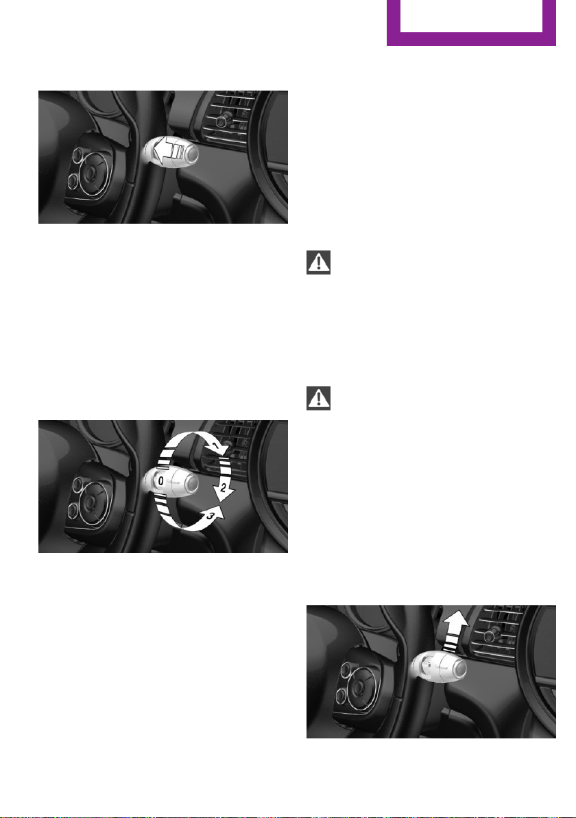
Driving
CONTROLS
Cleaning
Pull the lever.
The system sprays washer fluid on the wind‐
shield and activates the wipers briefly.
Windshield washer nozzles
The windshield washer nozzles are automati‐
cally heated while the ignition is switched on.
Rear window wiper
Switching on the rear window wiper
Fold-away position of the wipers
Concept
The fold-out position enables the wipers to be
folded away from the windshield.
General information
Helpful when changing the wiper blades or un‐
der frosty conditions, e.g.
Safety information
WARNING
If the wipers start moving in the folded
away state, body parts can be jammed or dam‐
age may occur to parts of the vehicle. There is a
risk of injury or risk of property damage. Make
sure that the vehicle is switched off when the
wipers are in the folded away state and the
wipers are folded in when switching on.◀
NOTE
If the wipers are frozen to the windshield,
the wiper blades can be torn off and the wiper
motor can overheat when switching on. There
is a risk of property damage. Defrost the wind‐
shield prior to switching the wipers on.◀
Turn the switch from idle position 0 upward, ar‐
row 1: interval mode. When reverse gear is en‐
gaged, the system switches to continuous op‐
eration.
Clean the rear window
In interval mode: turn the switch further, ar‐
row 2. The switch automatically returns to its
interval position when released.
In idle position: turn switch downward, arrow 3.
The switch automatically returns to its idle posi‐
tion when released.
Online Edition for Part no. 01 40 2 976 545 - X/16
Folding away the wipers
Switch the ignition on and off again.
1.
2. Press the wiper lever up beyond the point
of resistance and hold it for approx. 3 sec‐
onds, until the wipers remain in a nearly
vertical position
87
Page 88

CONTROLS
Driving
3. Fold the wipers all the way away from the
windshield.
Folding down the wipers
After the wipers are folded back down, the
wiper system must be reactivated.
Fold the wipers back down onto the wind‐
1.
shield.
2. Switch on the ignition.
3. Push wiper lever down. Wipers return to
their resting position and are ready again
for operation.
Washer fluid
ating materials into different bottles. Store op‐
erating materials out of reach of children.
United States: The washer fluid mixture ratio is
regulated by the U.S. EPA and many individual
states; do not exceed the allowable washer
fluid dilution ratio limits that apply. Follow the
usage instructions on the washer fluid con‐
tainer.
Use of BMW’s Windshield Washer Concentrate
or the equivalent is recommended.◀
WARNING
Washer fluid can ignite and catch fire on
contact with hot engine parts. There is a risk of
injury or risk of property damage. Only add
washer fluid when the engine is cooled down.
Next, fully close the lid of the washer fluid res‐
ervoir.◀
NOTE
Silicon-containing additives in the washer
fluid for the water-repelling effect on the win‐
dows can lead to damage to the washing sys‐
tem. There is a risk of property damage. Do not
add silicon-containing additives to the washer
fluid.◀
General information
All washer nozzles are supplied from one reser‐
voir.
Use a mixture of tap water and windshield
washer concentrate. If desired, a windshield
washer concentrate containing antifreeze can
be used.
Recommended minimum fill quantity:
0.2 US gal/1 liter.
Safety information
WARNING
Some antifreeze agents can contain
harmful substances and are flammable. There
is a risk of fire and a risk of injury. Observe the
instructions on the containers. Keep antifreeze
away from ignition sources. Do not refill oper‐
88
Online Edition for Part no. 01 40 2 976 545 - X/16
NOTE
Mixing different windshield washer con‐
centrates or antifreeze agents can damage the
washing system. There is a risk of property
damage. Do not mix different windshield
washer concentrates or antifreeze agents. Ob‐
serve the information and mixing ratios pro‐
vided on the containers.◀
Page 89

Driving
CONTROLS
Overview
The washer fluid reservoir is located in the en‐
gine compartment.
Malfunction
The use of undiluted windshield washer con‐
centrate or alcohol-based antifreeze can lead
to incorrect readings at temperatures below
+5 ℉/-15 ℃.
Manual transmission
Safety information
WARNING
An unsecured vehicle can begin to move
and possibly roll away. There is a risk of an acci‐
dent. Before exiting, secure the vehicle against
rolling.
In order to ensure that the vehicle is secured
against rolling away, observe the following:
▷ Set the parking brake.
▷ On uphill grades or on a downhill slope,
turn the front wheels in the direction of the
curb.
▷ On uphill grades or on a downhill slope,
also secure the vehicle, e.g., with a wheel
chock.◀
NOTE
When shifting to a lower gear, excessive
speeds can damage the engine. There is a risk
of property damage. When shifting into 5th or
6th gear, press the gearshift lever to the right.◀
Shifting
General information
The engine speed during shifting is adjusted
automatically for harmonious and dynamic
gear shifting.
Reverse gear
Select only when the vehicle is stationary.
To overcome the resistance push the gearshift
lever dynamically to the left and engage re‐
verse gear with a forward shifting movement.
Steptronic transmission
Concept
The Steptronic transmission combines the func‐
tions of an automatic transmission with the
possibility of manual shifting, if needed.
Safety information
WARNING
An unsecured vehicle can begin to move
and possibly roll away. There is a risk of an acci‐
dent. Before exiting, secure the vehicle against
rolling.
In order to ensure that the vehicle is secured
against rolling away, observe the following:
▷ Set the parking brake.
▷ On uphill grades or on a downhill slope,
turn the front wheels in the direction of the
curb.
▷ On uphill grades or on a downhill slope,
also secure the vehicle, e.g., with a wheel
chock.◀
Selector lever positions
Drive mode D
Selector lever position for normal vehicle oper‐
ation. All gears for forward travel are activated
automatically.
Online Edition for Part no. 01 40 2 976 545 - X/16
89
Page 90

CONTROLS
Driving
Reverse R
Engage selector lever position R only when the
vehicle is stationary.
Neutral N
The vehicle may be pushed or roll without en‐
gine power in selector lever position N, for in‐
stance in vehicle washes.
Parking position P
Selector level position, for instance for parking
the vehicle. The transmission blocks the drive
wheels in selector lever position P.
Engage selector lever position P only when the
vehicle is stationary.
Before exiting the vehicle, make sure that se‐
lector lever position P is set. Otherwise, the ve‐
hicle may begin to move.
Engaging selector lever positions
General information
To prevent the vehicle from creeping after you
select a drive mode, maintain pressure on the
brake pedal until you are ready to start.
The selector lever can only be taken out of se‐
lector lever position P if the ignition is on or the
engine is running.
With the vehicle stationary, depress the brake
pedal before shifting out of selector lever posi‐
tion P or N; otherwise, the shift block will not be
deactivated and the shift command will not be
executed.
To release the lock: with the brake pedal de‐
pressed, press the button on the front of the
selector lever, see arrow.
Kickdown
Kickdown is used to achieve maximum driving
performance. Step on the accelerator pedal be‐
yond the resistance point at the full throttle po‐
sition.
Sport program M/S
Concept
The shifting points and shifting times in the
Sport program are designed for a sportier driv‐
ing style. The transmission, for instance shifts
up later and the shifting times are shorter.
Activating the sport program
Releasing the selector lever lock
A lock prevents the inadvertent switching to se‐
lector lever position R or the inadvertent
change from selector lever position P.
90
Online Edition for Part no. 01 40 2 976 545 - X/16
Press the selector lever to the left out of selec‐
tor lever position D.
The engaged gear is displayed in the instru‐
ment cluster, for instance S1.
The sport program of the transmission is acti‐
vated.
Page 91

Driving
CONTROLS
Ending the Sport program
Push the selector lever to the right.
D is displayed in the instrument cluster.
Manual mode M/S
Concept
Manual gear-shifting is possible in manual
mode.
Activating manual mode
Press the selector lever to the left out of selec‐
tor lever position D, arrow 1. Next, push the se‐
lector lever forward or pull it backward, ar‐
row 2.
Manual mode M/S becomes active and the gear
is changed.
The engaged gear is displayed in the instru‐
ment cluster, for instance M1.
Shifting
To shift down: press the selector lever forward.
To shift up: pull the selector lever rearwards.
The Steptronic transmission continues shifting
automatically in certain situations, for instance
when certain engine speed limits are reached.
Avoiding automatic upshifting
Once a particular engine speed is attained, M/S
manual mode is automatically upshifted as
needed.
For vehicles with Steptronic Sport transmission,
automatic shift operations are not performed if
one of the following conditions is met:
▷ DSC is deactivated.
▷ TRACTION is activated.
In addition, there is no downshifting for kick‐
down.
With the respective transmission version, the
lowest possible gear can be selected by simul‐
taneously operating the kickdown and the left
shift paddles. This is not possible by switching
briefly via the shift paddles from selector lever
position D to manual mode M/S.
Ending the manual mode
Push the selector lever to the right.
D is displayed in the instrument cluster.
Shift paddles for Steptronic Sport
transmission
Concept
The shift paddles on the steering wheel allow
you to shift gears quickly while keeping both
hands on the steering wheel.
General information
Shifting
Gears will only be shifted at appropriate engine
and road speeds, for instance downshifting is
not possible if the engine speed is too high.
Switching into manual mode
In selector lever position S, actuating a shift
paddle switches into manual mode perma‐
nently.
In selector lever position D, actuating a shift
paddle switches into manual mode temporarily.
Switching into automatic mode
In selector lever position D, after conservative
driving in manual mode without acceleration or
Online Edition for Part no. 01 40 2 976 545 - X/16
91
Page 92

CONTROLS
Driving
shifting via the shift paddles for a certain
amount of time, the transmission switches back
to automatic mode.
It is possible to switch from manual mode into
the automatic mode as follow:
▷ Pull and hold right shift paddle.
▷ In addition to the briefly pulled right shift
paddle, briefly pull the left shift paddle.
Shifting
▷ To shift up: briefly pull right shift paddle.
▷ To shift down: briefly pull left shift paddle.
▷ The lowest possible gear can be selected by
pulling and holding the left shift paddle.
The selected gear is briefly displayed in the in‐
strument cluster, followed by the current gear.
Before unlocking the transmission lock man‐
ually, set the parking brake to prevent the vehi‐
cle from rolling away.
1. Loosen the selector lever sleeve together
with the lower retaining ring and, if re‐
quired, the MINI Driving Modes switch from
the center console. To do so, pull the re‐
taining ring and, if required, the MINI Driv‐
ing Modes switch upward at the rear edge.
2. Lift the sleeve. Unplug the cable connector,
if needed.
3. Using the screwdriver from the onboard ve‐
hicle tool kit, refer to page 231, press the
yellow release lever downward, see arrow.
Displays in the instrument cluster
The selector lever position is dis‐
played, for example P.
Manually release the transmission lock
If the selector lever is locked in selector lever
position P despite the ignition being turned on,
the brake pedal being depressed and the but‐
ton on the selector lever being pressed, the
transmission lock can be unlocked manually:
92
Online Edition for Part no. 01 40 2 976 545 - X/16
4. Move the selector lever slightly toward the
rear; to do this press the button on the
front of the selector lever.
Release the release lever.
5. Bring the selector lever into the desired po‐
sition.
For additional information, see the chapter on
tow-starting and towing.
Page 93

Driving
CONTROLS
Steptronic Sport transmission: Launch
Control
Concept
Launch Control enables optimum acceleration
on surfaces with good traction under dry sur‐
rounding conditions.
General information
The use of Launch Control causes premature
component wear since this function represents
a very heavy load for the vehicle.
Do not use Launch Control during the break-in,
refer to page 184, period.
To start with Launch Control do not steer the
steering wheel.
Requirements
Launch Control is available when the engine is
warmed up, that is, after uninterrupted driving
of at least 6 miles/10 km.
Start with launch control
While the engine is running:
Repeated use during a trip
After Launch Control was used, the transmis‐
sion must cool down for approx. 5 minutes, be‐
fore Launch Control can be used again.
After using Launch Control
To increase vehicle stability, activate DSC Dy‐
namic Stability Control again.
System limits
An experienced driver may be able to achieve
better acceleration values in DSC OFF mode.
1. Press button and select SPORT with
the MINI Driving Modes switch.
The instrument cluster displays TRACTION
in combination with SPORT. The DSC OFF
indicator light lights up.
2. Engage selector lever position S.
3. With the left foot, forcefully press down on
the brake.
4. Step on the accelerator pedal beyond the
resistance point at the full throttle position,
kickdown.
A flag symbol is displayed in the instrument
cluster.
5. The starting engine speed adjusts. Within
3 seconds, release the brake.
Online Edition for Part no. 01 40 2 976 545 - X/16
93
Page 94

CONTROLS
Displays
Displays
Vehicle features and op‐
tions
This chapter describes all standard, countryspecific and optional features offered with the
series. It also describes features that are not
Instrument cluster
Overview
necessarily available in your vehicle, e. g., due
to the selected options or country versions. This
also applies to safety-related functions and sys‐
tems. When using these functions and systems,
the applicable laws and regulations must be
observed.
1 Tachometer 99
2 Indicator/warning lights
3 Speedometer
94
4 Fuel gauge 99
5 Display/reset miles 99
6 Electronic displays 95
Online Edition for Part no. 01 40 2 976 545 - X/16
Page 95

Electronic displays
Displays
CONTROLS
1 Driver assistance systems
Messages, for instance Check Control
Time 100
External temperature 99
Selection lists 103
Check Control
Concept
The Check Control system monitors functions in
the vehicle and notifies you of malfunctions in
the monitored systems.
General information
A Check Control message is displayed as a com‐
bination of indicator or warning lights and SMS
text messages in the instrument cluster and in
the Head-up Display.
In addition, an acoustic signal may be output
and a SMS text message may appear on the
Control Display.
Total miles/trip odometer 99
Onboard computer 103
2 Selector lever position 89
Gear shift indicator 101
3 MINI Driving Modes switch status 137
Indicator/warning lights
General information
The indicator and warning lights can light up in
a variety of combinations and colors.
Several of the lights are checked for proper
functioning and light up temporarily when the
engine is started or the ignition is switched on.
Red lights
Safety belt reminder
Indicator lamp flashes or illuminates:
safety belt on the driver or front pas‐
senger side is not buckled. The safety
belt reminder can also be activated if objects
are placed on the front passenger seat.
Online Edition for Part no. 01 40 2 976 545 - X/16
95
Page 96

CONTROLS
Displays
Make sure that the safety belts are positioned
correctly.
Airbag system
Airbag system and belt tensioner are
not working.
Have the vehicle checked immediately
by a dealer’s service center or another qualified
service center or repair shop.
Parking brake
The parking brake is set.
Release the parking brake, refer to
page 83.
Brake system
Braking system impaired. Continue to
drive moderately.
Have the vehicle checked immediately
by a dealer’s service center or another
qualified service center or repair shop.
Approach control warning
Indicator light illuminates: advance
warning is issued, for example when
there is the impending danger of a colli‐
sion or the distance to the vehicle ahead is too
small.
Increase distance.
Indicator light flashes: acute warning of the im‐
minent danger of a collision when the vehicle
approaches another vehicle at a relatively high
differential speed.
Intervention by braking or make an evasive
maneuver.
Pedestrian warning
If a collision with a person detected in
this way is imminent, the symbol lights
up and a signal sounds.
Orange lights
Active Cruise Control
The number bars shows the selected
distance from the vehicle driving ahead.
Camera-based cruise control, refer to
page 139.
Vehicle detection, Active Cruise Control
Indicator lamp illuminates: a vehicle has
been detected ahead of you.
Indicator lamp flashes: the conditions
are not adequate for the system to work.
The system was deactivated but applies the
brakes until you actively resume control by
pressing on the brake pedal or accelerator
pedal.
Yellow lights
Anti-lock Braking System ABS
Braking force boost may not be work‐
ing. Avoid abrupt braking. Take the lon‐
ger braking distance into account.
Have the system immediately checked
by a dealer’s service center or another
qualified service center or repair shop.
DSC Dynamic Stability Control
The indicator light flashes: DSC controls
the drive and braking forces. The vehi‐
cle is stabilized. Reduce speed and
adapt driving style to the driving circumstances.
The indicator light lights up: DSC has malfunc‐
tioned.
Have the system checked by a dealer’s service
center or another qualified service center or re‐
pair shop.
DSC Dynamic Stability Control, refer to
page 135.
96
Online Edition for Part no. 01 40 2 976 545 - X/16
Page 97

Displays
CONTROLS
DSC Dynamic Stability Control is deactivated
or DTC Dynamic Traction Control is activated
DSC Dynamic Stability Control is deacti‐
vated or DTC Dynamic Traction Control
is activated.
DSC Dynamic Stability Control, refer to
page 135, and DTC Dynamic Traction Control,
refer to page 136.
Flat Tire Monitor FTM
The Flat Tire Monitor signals a loss of
tire inflation pressure in a tire.
Reduce your speed and stop cautiously.
Avoid sudden braking and steering maneuvers.
Flat Tire Monitor, refer to page 125.
Tire Pressure Monitor TPM
The indicator light illuminates.
The Tire Pressure Monitor reports a low
tire inflation pressure or a flat tire.
Observe the information in the Check Control
message.
The indicator light flashes and then illuminates
continuously.
No flat tire or loss of tire inflation pressure can
be detected.
▷ Interference caused by systems or devices
with the same radio frequency: after leav‐
ing the area of the interference, the system
automatically becomes active again.
▷ TPM was unable to complete the reset. Re‐
set the system again.
▷ A wheel without TPM electronics is
mounted: have it checked by a dealer’s
service center or another qualified service
center or repair shop as needed.
▷ Malfunction: have the system checked by a
dealer’s service center or another qualified
service center or repair shop.
Tire Pressure Monitor, refer to page 121.
Steering system
Steering system in some cases not
working.
Have the steering system checked by a
dealer’s service center or another qualified
service center or repair shop.
Emissions
▷ The warning light lights up:
Emissions are deteriorating. Have
the vehicle checked as soon as pos‐
sible.
▷ The warning light flashes under certain cir‐
cumstances:
This indicates that there is excessive misfir‐
ing in the engine.
Reduce the vehicle speed and have the sys‐
tem checked immediately; otherwise, seri‐
ous engine misfiring within a brief period
can seriously damage emission control
components, in particular the catalytic con‐
verter.
Socket for Onboard Diagnosis, refer to
page 230.
Rear fog light
Rear fog lights are activated.
Rear fog lights, refer to page 115.
Green lights
Turn signal
Turn signal switched on.
Unusually rapid flashing of the indicator
light indicates that a turn signal bulb
has failed.
Turn signal, refer to page 84.
Online Edition for Part no. 01 40 2 976 545 - X/16
97
Page 98

CONTROLS
Displays
Parking lights, headlight
Parking lights or headlights are acti‐
vated.
Parking lights/low beams, headlight
control, refer to page 112.
Front fog lights
Front fog lights are activated.
Front fog lights, refer to page 115.
High-beam Assistant
High-beam Assistant is switched on.
High beams are switched on and off au‐
tomatically depending on the traffic sit‐
uation.
High-beam Assistant, refer to page 114.
Cruise control
The system is switched on. It maintains
the speed that was set using the control
elements on the steering wheel.
Blue lights
High beams
High beams are activated.
High beams, refer to page 85.
Hiding Check Control messages
Continuous display
Some Check Control messages are displayed
continuously and are not cleared until the mal‐
function is eliminated. If several malfunctions
occur at once, the messages are displayed con‐
secutively.
These messages can be hidden for approx.
8 seconds. After this time, they are displayed
again automatically.
Temporary display
Other Check Control messages are hidden au‐
tomatically after approx. 20 seconds. They are
stored and can be displayed again later.
Displaying stored Check Control
messages
Via the onboard monitor:
"My MINI"
1.
2. "Vehicle status"
3. "Check Control"
4. Select the SMS text message.
Display
Check Control
At least one Check Control message is
displayed or is stored.
SMS text messages
SMS text messages in combination with a sym‐
bol in the instrument cluster explain a Check
Control message and the meaning of the indi‐
cator and warning lights.
Press and hold button on signal lever.
98
Online Edition for Part no. 01 40 2 976 545 - X/16
Supplementary SMS text messages
Additional information, such as on the cause of
an error or the required action, can be called up
via Check Control.
With urgent messages the added text will be
automatically displayed on the Control Display.
Page 99

Displays
CONTROLS
Further help
Depending on the Check Control message, fur‐
ther help can be selected.
Via the onboard monitor:
1. "My MINI"
2. "Vehicle status"
3. "Check Control"
4. Select the desired text message.
5. Select the desired setting.
▷ "Owner's Manual"
Display additional information about
the Check Control message in the Inte‐
grated Owner's Manual.
▷ "Service request"
Contact a dealer’s service center or an‐
other qualified service center or repair
shop.
▷ "MINI Roadside Assistance"
Contact Roadside Assistance.
Messages after trip completion
Special messages displayed while driving are
displayed again after the ignition is switched
off.
Tachometer
Always avoid engine speeds in the red warning
field. In this range, the fuel supply is reduced to
protect the engine.
Odometer and trip odom‐
eter
Concept
The total number of kilometers driven and the
number of kilometers driven since the last reset
are displayed in the instrument cluster.
Reset the trip odometer
Press the knob.
▷ The odometer is displayed
when the ignition is switched
off.
▷ When the ignition is switched
on, the trip odometer is re‐
set.
External temperature
Fuel gauge
Vehicle tilt position may cause
the display to vary.
The arrow beside the fuel pump
symbol shows which side of the
vehicle the fuel filler flap is on.
Notes on refueling, refer to page 198.
When the reserve fuel level is reached,
the yellow indicator lamp is illuminated.
Online Edition for Part no. 01 40 2 976 545 - X/16
WARNING
Even at temperatures above +37 ℉/+3 ℃
there can be a risk of icy roads, e.g., on bridges
or shady sections of road. There is a risk of an
accident. Adjust your driving style to the
weather conditions at low temperatures.◀
If the indicator drops to
+37 ℉/+3 ℃, a signal sounds.
A Check Control message is dis‐
played.
There is an increased risk of ice
on roads.
99
Page 100

CONTROLS
Displays
Time
The time is displayed in the in‐
strument cluster.
The time can be set via the on‐
board monitor.
Date
The date is displayed in the in‐
strument cluster.
The date can be set via the on‐
board monitor.
Range
Display
With a low remaining range:
▷ A Check Control message is
displayed briefly.
▷ The remaining range is
shown on the onboard com‐
puter.
▷ With a dynamic driving style, for instance
taking curves aggressively, the engine func‐
tion is not always ensured.
The Check Control message appears continu‐
ously below a range of approx. 30 miles/50 km.
NOTE
With a range of less than 30 miles/50 km
it is possible that the engine will no longer have
sufficient fuel. Engine functions are not ensured
anymore. There is a risk of property damage.
Refuel promptly.◀
Displaying the cruising range
Via the onboard monitor:
"My MINI"
1.
2. "System settings"
3. "Displays"
4. "Instrument panel"
5. "Range"
Current fuel consump‐
tion
Concept
Displays the current fuel consumption. Check
whether you are currently driving in an efficient
and environmentally-friendly manner.
Displaying the current fuel
consumption
Via the onboard monitor:
"My MINI"
1.
2. "System settings"
3. "Displays"
4. "Instrument panel"
5. "Current consumption"
Service requirements
Concept
The function displays the necessary service re‐
quirements and the corresponding mainte‐
nance procedures.
General information
After the ignition is turned on the instrument
cluster briefly displays available driving distance
or time to the next scheduled maintenance.
A service advisor can read out the current serv‐
ice requirements from your remote control.
100
Online Edition for Part no. 01 40 2 976 545 - X/16
 Loading...