

Page 1

Operator’s Manual
HyLED 760/760M/730/730M Series
LED Surgical Lights
Page 2

Page 3

Copyright
The device bears CE mark indicating its conformity with the provisions of the Council Directive
93/42/EEC concerning medical devices and fulfills the essential requirements of Annex I of this
directive.
The device complies with the requirements of EN/IEC 60601-1-2 “Electromagnetic
Compatibility – Medical Electrical Equipment”.
© 2013-2016 Nanjing Mindray Bio-Medical Electronics Co., Ltd. All rights Reserved.
For this Operator’s Manual, the issued date is 2016-05 (Version: 6.0).
Intellectual Property Statement
NANJING MINDRAY BIO-MEDICAL ELECTRONICS CO., LTD. (hereinafter called Mindray)
owns the intellectual property rights to this Mindray device and this manual. This manual may
refer to information protected by copyrights or patents and does not convey any license under
the patent rights or copyright of Mindray, or of others.
Mindray intends to maintain the contents of this manual as confidential information. Disclosure
of the information in this manual in any manner whatsoever without the written permission of
Mindray is strictly forbidden.
Release, amendment, reproduction, distribution, rental, adaption and translation or any other
derivative work of this manual in any manner whatsoever without the written permission of
Mindray is strictly forbidden.
, , are the trademarks, registered or otherwise, owned by
Shenzhen Mindray Bio-Medical Electronics Co., Ltd. , , HyLED are the
trademarks, registered or otherwise, owned by Nanjing Mindray Bio-Medical Electronics Co.,
Ltd in China and other countries. All other trademarks that appear in this manual are used only
for informational or editorial purposes. They are the property of their respective owners.
I
Page 4
Responsibility on the Manufacturer Party
Contents of this manual are subject to change without prior notice.
All information contained in this manual is believed to be correct. Mindray shall not be liable for
errors contained herein or for incidental or consequential damages in connection with the
furnishing, performance, or use of this manual.
Mindray is responsible for the effects on safety, reliability and performance of this device, only
if:
all installation operations, expansions, changes, modifications and repairs of this device
are conducted by Mindray authorized personnel.
the electrical installation of the relevant room complies with the applicable national and
local requirements, and
the device is used in accordance with the instructions for use.
This device must be operated by skilled/trained clinical professionals.
It is important for the hospital or organization that employs this device to
carry out a reasonable service/maintenance plan. Neglect of this may result
in machine breakdown or personal injury.
II
Page 5

Warranty
THIS WARRANTY IS EXCLUSIVE AND IS IN LIEU OF ALL OTHER WARRANTIES,
EXPRESSED OR IMPLIED, INCLUDING WARRANTIES OF MERCHANTABILITY OR
FITNESS FOR ANY PARTICULAR PURPOSE.
Exemptions
Mindray's obligation or liability under this warranty does not include any transportation or other
charges or liability for direct, indirect or consequential damages or delay resulting from the
improper use or application of the device or the use of parts or accessories not approved by
Mindray or repairs by people other than Mindray authorized personnel.
This warranty shall not extend to:
Malfunction or damage caused by improper use or man-made failure.
Malfunction or damage caused by unstable or out-of-range power input.
Malfunction or damage caused by force majeure such as fire and earthquake.
Malfunction or damage caused by improper operation or repair by unqualified or
unauthorized service people.
Malfunction of the device or part whose serial number is not legible enough.
Others not caused by device or part itself.
Return Policy
Return Procedure
In the event that it becomes necessary to return this device or part of this device to Mindray,
the following procedure should be followed:
Return authorization: Contact the Customer Service Department and obtain a Customer
Service Authorization number. This number must appear on the outside of the shipping
container. Returned shipments will not be accepted if the number is not clearly visible. Please
provide the model number, serial number, and a brief description of the reason for return.
Freight policy: The customer is responsible for freight charges when this device is shipped to
Mindray for service (this includes customs charges).
Return address: Please send the part(s) or device to the address offered by the Customer
Service Department.
III
Page 6

Contact Information
Manufacturer: Nanjing Mindray Bio-Medical Electronics Co., Ltd.
Address: 666# Middle Zhengfang Road, Jiangning, 211100 Nanjing, Jiangsu,
P.R.China
Tel: +86 25 66082666
Fax: +86 755 26582680-26666
EC-Representative: Shanghai International Holding Corp. GmbH (Europe)
Address: Eiffestrasse 80, 20537 Hamburg, Germany
Tel: 0049-40-2513175
Fax: 0049-40-255726
IV
Page 7

Table of Contents
1 System Overview ································································ 1-1
1.1 Main Components ........................................................................ 1-1
1.2 Definitions .................................................................................... 1-5
1.2.1 Graphical Symbols .............................................................. 1-5
1.2.2 Safety Notes........................................................................ 1-6
1.3 Intended Use................................................................................ 1-7
1.4 Fundamental Safety Instructions .................................................. 1-8
1.4.1 Instructions against Personal Injury ..................................... 1-8
1.4.2 Instructions against Device Damage .................................... 1-9
2 Daily Operations ································································· 2-1
2.1 Preparations................................................................................. 2-1
2.1.1 General ............................................................................... 2-1
2.1.2 HyLED 760/730 ................................................................... 2-2
2.1.3 HyLED 760M/730M ............................................................. 2-2
2.1.4 Warning Label (HyLED 760M/730M) .................................... 2-3
2.2 Using Lighthead ........................................................................... 2-4
2.2.1 General ............................................................................... 2-4
2.2.2 Installing/Removing Sterilizable Handle ............................... 2-4
2.2.3 Adjusting Lighthead Position ................................................ 2-5
2.2.4 Using Control Panel............................................................. 2-7
2.2.5 Using Touch Control Panel ................................................ 2-11
2.2.6 Using Wall Control Panel (optional).................................... 2-15
2.2.7 Using Touch Wall Control Panel (optional) ......................... 2-16
2.3 Using Carrier-arm Camera (optional) .......................................... 2-18
2.3.1 General ............................................................................. 2-18
2.3.2 Installing/Removing Sterilizable Handle of Carrier-arm
Camera………. .......................................................................... 2-18
2.3.3 Using Control Panel........................................................... 2-19
2.3.4 Using Touch Control Panel/Wall Control Panel/Touch Wall
Control Panel (optional) .............................................................. 2-20
2.3.5 Using Infrared Remote Control (optional) ........................... 2-20
2.4 Using Rotatable Integrated Camera (optional) ............................ 2-22
2.4.1 General ............................................................................. 2-22
2.4.2 Installing Rotatable Integrated Camera .............................. 2-22
2.4.3 Installing/Removing Sterilizable Handle of Rotatable Integrated
Camera………… ........................................................................ 2-23
2.4.4 Removing Rotatable Integrated Camera ............................ 2-24
2.4.5 Using Touch Control Panel ................................................ 2-24
2.4.6 Using Wall Control Panel/Touch Wall Control Panel
1
Page 8

Table of Contents
(optional)…………… ......................................................………..2-24
2.4.7 Using Infrared Remote Control (optional) ........................... 2-24
2.5 Using Display (optional).............................................................. 2-25
2.5.1 For SD Camera ................................................................. 2-25
2.5.2 For HD Camera ................................................................. 2-25
2.5.3 Installing/Removing Sterilizable Handle of Display ............. 2-26
3 Maintenance ······································································ 3-1
3.1 Maintenance Period ..................................................................... 3-1
3.2 Cleaning/Disinfection .................................................................... 3-2
3.2.1 Maintaining Lighthead Exterior ............................................. 3-2
3.2.2 Maintaining Touch Screen (optional) .................................... 3-4
3.2.3 Maintaining Sterilizable Handle ............................................ 3-5
3.3 Maintaining Backup Battery Module (optional) .............................. 3-6
3.3.1 Maintenance Period............................................................. 3-6
3.3.2 Maintenance Method ........................................................... 3-6
3.4 Calibrating Touch Screen of Touch Control Panel (optional) .......... 3-7
3.5 Replacing Battery of Infrared Remote Control (optional) ............... 3-9
3.6 Adjusting System ....................................................................... 3-10
3.6.1 Adjusting Braking Force ..................................................... 3-10
3.6.2 Adjusting Spring Arm ......................................................... 3-11
3.6.3 Adjusting Gimbal Joint ....................................................... 3-14
3.6.4 Adjusting Braking Force of Rotatable Control Panel/Touch
Control Panel (optional) .............................................................. 3-16
4 Troubleshooting ································································· 4-1
5 Appendices ······································································· 5-1
A Technical Specifications................................................................ 5-1
A.1 Classification ....................................................................... 5-1
A.2 Environment ........................................................................ 5-3
A.3 Optical Performance ............................................................ 5-7
A.4 Camera Specifications ......................................................... 5-8
A.5 EMC .................................................................................... 5-9
B Index .......................................................................................... 5-14
2
Page 9
1 System Overview
1.1 Main Components
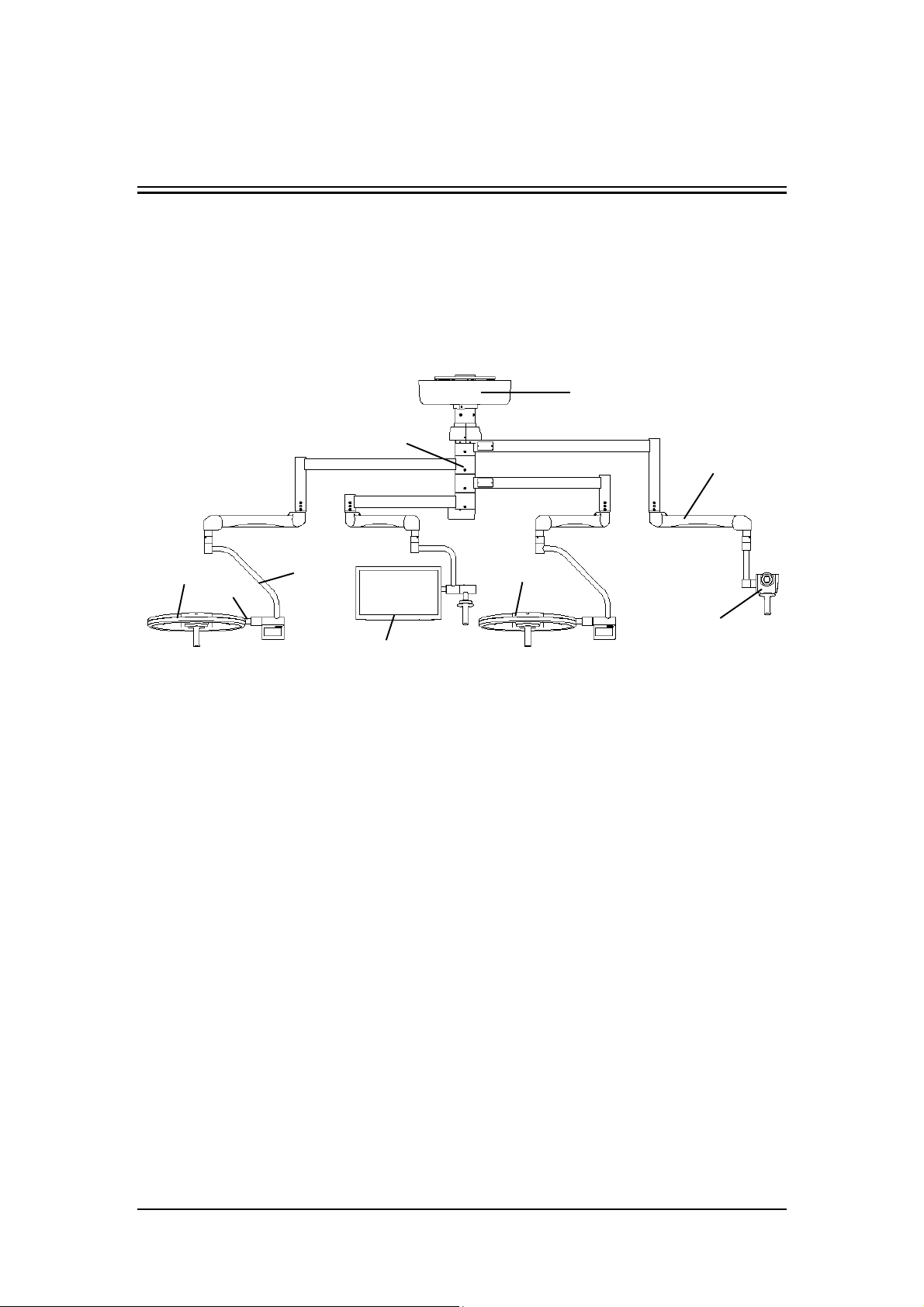
The main components of HyLED 760/730/760M/730M series surgical lights are shown in the
figures below.
1
2
3
7
5
1 Ceiling Cover 2 Swivel Arm Assembly
3 Standard Spring Arm 4 Vertical Gimbal Joint
5 Horizontal Gimbal Joint 6 HyLED 760 Lighthead
7 HyLED 730 Lighthead 8 Carrier-arm Camera (optional)
9 Display (optional)
4
9
Figure 1-1 HyLED 760/730 with carrier-arm camera
6
8
1-1
Page 10
System Overview
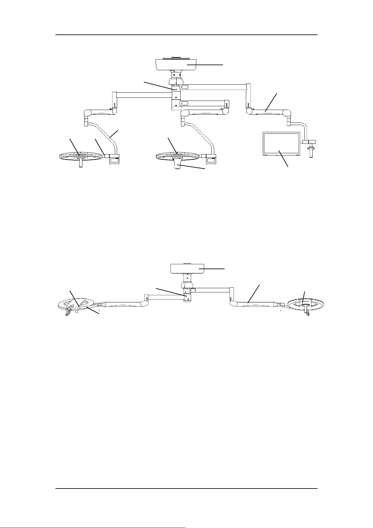
8 9
6
1
2
4
7
1 Ceiling Cover 2 Swivel Arm Assembly
3 Standard Spring Arm 4 Vertical Gimbal Joint
5 Horizontal Gimbal Joint 6 HyLED 760 Lighthead
7 HyLED 730 Lighthead 8 Display (optional)
9 Integrated Camera (optional)
5
Figure 1-2 HyLED 760/730 with integrated camera
6
3
1
5
4
Figure 1-3 HyLED 760/730 for low ceiling height
1 Ceiling Cover 2 Swivel Arm Assembly
3 LCH (Low Ceiling Height) Spring Arm
(optional)
5 HyLED 760 Lighthead 6 HyLED 730 Lighthead
2
4 Gimbal Joint
3
1-2
Page 11
System Overview
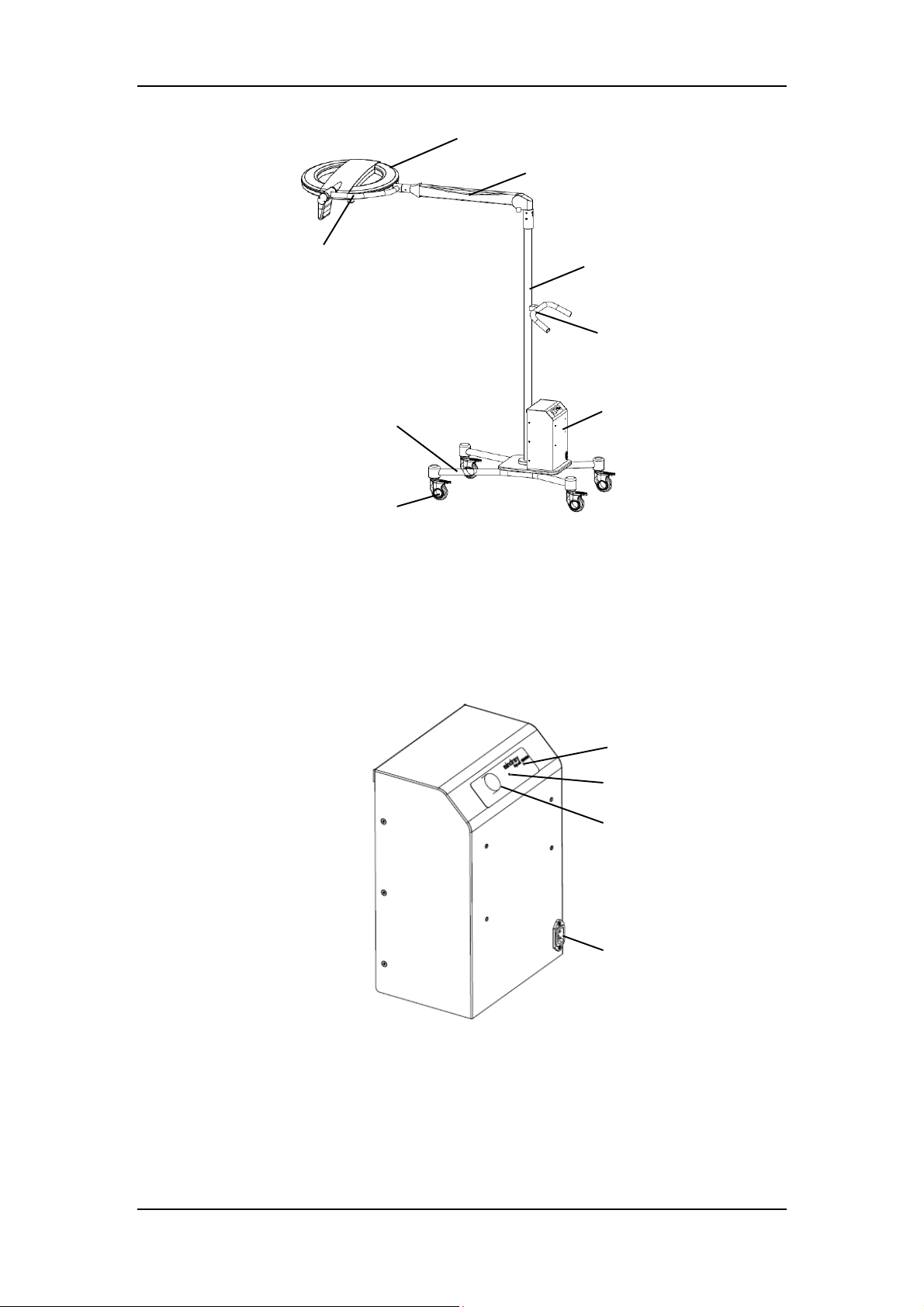
1
2 4 5 3
6 7
2 3 4
8
Figure 1-4 HyLED 760M/730M
1 Lighthead 2 Spring Arm
3 Pole 4 Handle
5 Power Module 6 Castors
7 Base 8 Gimbal Joint
1
Figure 1-5 HyLED 760M/730M power module
1 Main Switch 2 AC Indicator
3 Battery Indicator 4 Power Connector
1-3
Page 12
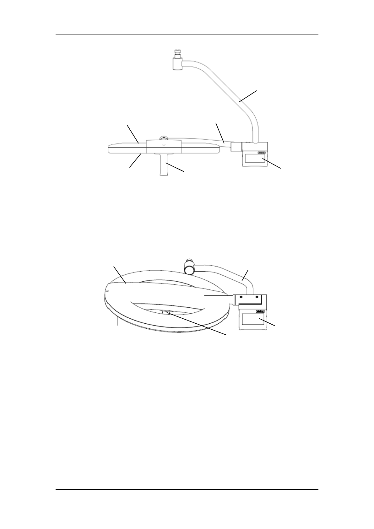
System Overview
6
1
2
Figure 1-6 HyLED 760/730 lighthead
1 Lamp Housing Hood 2 Glass
3 Sterilizable Handle Assembly 4 Control Panel (optional)/Touch Control
5 Horizontal Gimbal Joint 6 Vertical Gimbal Joint
1
3
Panel
5
4
5
2
3
Figure 1-7 HyLED 760M/730M lighthead
1 Lamp Housing Hood 2 Glass
3 Sterilizable Handle Assembly 4 Control Panel (optional)/Touch Control
Panel
5 Gimbal Joint
1-4
4
Page 13
System Overview
1.2 Definitions
1.2.1 Graphical Symbols
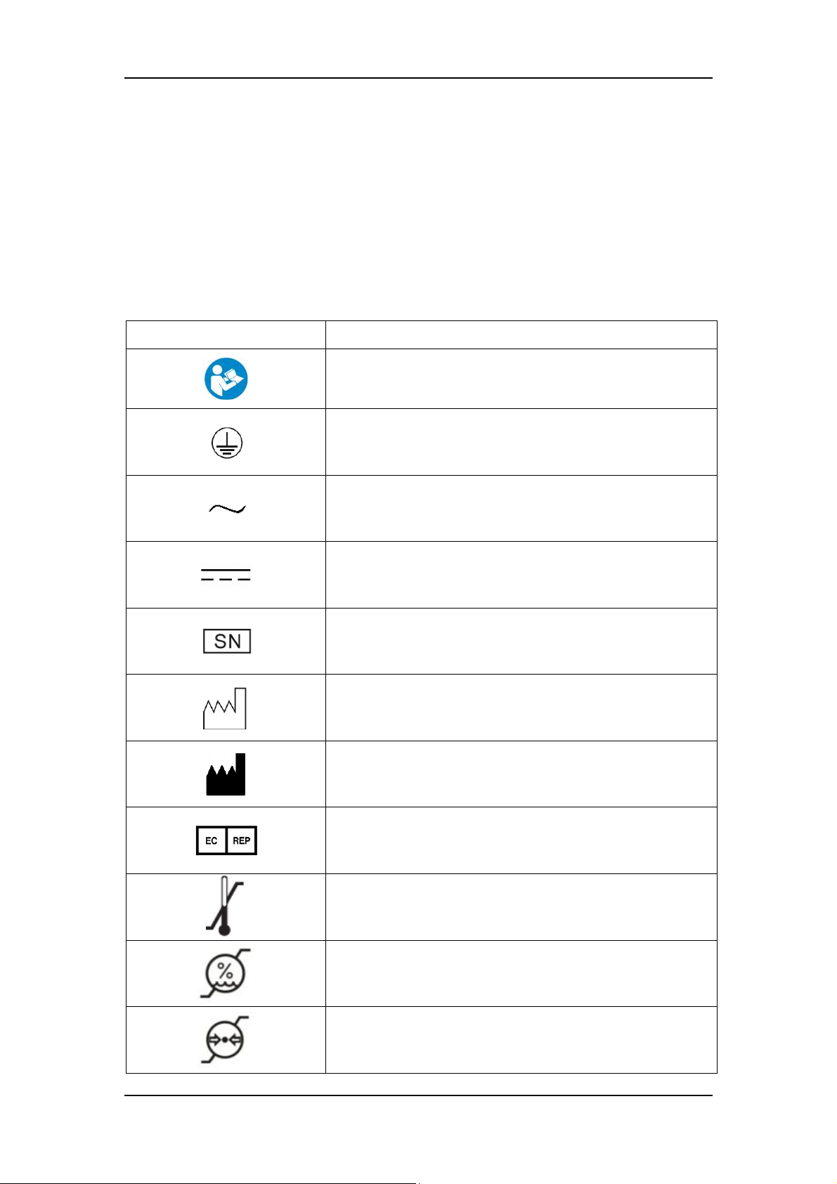
You may see the following symbols on the surgical light.
Table 1-1 Symbol definition
Symbol Meaning
Caution, consult accompanying documents
Protective earth (ground)
Alternating current
Direct current
Serial number
Date of manufacture
Manufacturer
Authorized representative in the European Community
Temperature limitation
Humidity limitation
Atmospheric pressure limitation
1-5
Page 14
System Overview
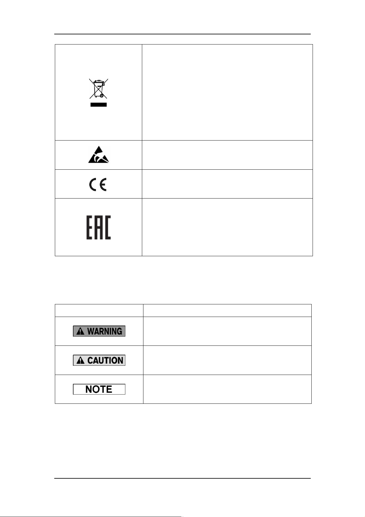
WEEE label
The following definition of the WEEE label applies to EU
member states only: the use of this symbol indicates that this
product should not be treated as household waste. By
ensuring that this product is disposed of correctly, you will
help prevent bringing potential negative consequences to the
environment and human health. For more detailed
information with regard to returning and recycling this
product, please consult the distributor from whom you
purchased the product.
ESD (Electrostatic Discharge) warning
Labelling for Class I products. Developed and marketed in
compliance with medical device directive 93/42/EEC.
Unified circulation mark indicates that products marked them
passed all specified in the technical regulations of the
Customs Union of the procedure for the assessment
(confirmation) of conformity and complies with the
requirements applicable to all the products technical
regulations of the Customs Union.
1.2.2 Safety Notes
Note Meaning
Table 1-2 Definition of safety notes
Read the statement below the symbol. The statement alerts
you to an operating hazard that can cause personal injury.
Read the statement below the symbol. The statement alerts
you to possible damage to the device or other property.
Read the statement below the symbol. The statement alerts
you to information that requires your attention.
1-6
Page 15

System Overview
1.3 Intended Use
The HyLED 760/HyLED 730/HyLED 760M/HyLED 730M series surgical lights are intended for
operation, treatment and diagnosis within the operating/treatment room.
The double-lighthead or triple-lighthead configuration can be used in the operating room as a
fail-safe surgical illumination system.
The single-lighthead configuration can be used for the diagnosis/treatment procedure in the
operating/treatment room. No harm will be done to the patient even if the procedure is
interrupted by illumination failure.
The mobile configuration can be used as an additional light to supplement an existing surgical
light in the operating room. It can be used for the diagnosis/treatment procedure in the
operating/treatment room. No harm will be done to the patient even if the procedure is
interrupted by illumination failure.
See the table below for all the available models and their configurations.
Table 1-3 Available models and configurations
Model Configuration
HyLED 760
HyLED 730
HyLED 760/760 Double lightheads
HyLED 730/730 Double lightheads
HyLED 760/730 Double lightheads
HyLED 760/760/760 Triple lightheads
HyLED 760/760/730 Triple lightheads
HyLED 760/730/730 Triple lightheads
HyLED 730/730/730 Triple lightheads
HyLED 760M Mobile
HyLED 730M Mobile
Single lighthead
Single lighthead
Contents of this manual are based on the full configuration of the surgical
light. Some of them may not apply to your light. Use your light according to
the actual configuration. If you have any questions, contact the customer
service department authorized by Nanjing Mindray or your local distributor.
1-7
Page 16

System Overview
1.4 Fundamental Safety Instructions
1.4.1 Instructions against Personal Injury
The surgical light is to be used for its intended purposes only. Do not use it
for other purposes.
The surgical light is to be installed, maintained and serviced by personnel
authorized by Nanjing Mindray only.
The surgical light is to be operated by trained personnel only.
Be sure to read and understand this manual before operating the surgical
light.
Be sure to follow this manual to train staff in the operation, maintenance and
safe use of the surgical light.
To avoid the risk of electric shock, the surgical light must only be connected
to a mains supply with protective earth.
Make sure the electrical installation of building complies with the
requirements of IEC 60364-7-710.
Do not direct the light source towards human eyes. Otherwise, it may cause
personal injury.
Long-time exposure to the light source may cause eye fatigue. Be sure to
select a proper illuminance level for long-time surgeries.
Do not use the surgical light within a flammable and/or explosive area.
Be sure to adjust the illuminance level based on the needs of the operation.
Note that there is a risk of too much heat in the operating field by
overlapping the light fields of several lightheads, in which case the surgical
light system may exceed an total irradiance of 1 000 W/m².
After each sterilization and before each new use of the sterilizable handle,
be sure to check if it has any sign of wear, such as cracking and color
fading, and install it correctly until it clicks.
When installing the surgical light, make sure that it is connected to a switch
that can shut off the mains supply. This switch is not included in the
surgical light. Before maintaining or servicing the surgical light, be sure to
shut off the mains supply first.
Before connecting any equipment to the surgical light, make sure the
1-8
Page 17

System Overview
equipment is suitable for use within the patient environment.
To avoid possible environmental contamination, used surgical lights,
including their batteries and components, shall be disposed of in
compliance with local governmental or hospital regulations.
Any equipment connected to the surgical light shall comply with the
relevant EN/IEC standards (e.g., EN/IEC 60950 information technology
equipment safety standard, EN/IEC 60601-1 medical equipment standard
and its relevant particular standards, and the like). It is the responsibility of
the people, who connect additional equipment to the surgical light and
configure the whole system, to verify that the system complies with the
requirements of EN/IEC 60601-1 and EN/IEC 60601-1-2. If you have any
questions regarding these requirements, consult the customer service
department authorized by Nanjing Mindray or your local distributor.
Do not use the LED surgical lights in an MRI environment.
Do not modify the surgical light without authorization of Nanjing Mindray.
Do not position the mobile surgical light in the place where it is difficult to
operate the disconnection device.
If an LED card is defective, be sure to contact the customer service
department authorized by Nanjing Mindray.
The surgical light may be used together with other manufacturers' devices
(e.g. displays). Be sure to refer to each manufacturer's instructions for how
to use the device.
1.4.2 Instructions against Device Damage
Exercise caution when transporting or moving the surgical light. Do not
damage it during transportation or movement.
Be sure to use spare parts supplied by Nanjing Mindray only.
The portable or mobile RF communication device can affect operation of
medical devices. Make sure that the surgical light is installed in a proper
environment. See chapter A.5 for details.
Connector pins with an ESD warning symbol should not be touched and no
connections should be made between these connectors without
implementing ESD protective measures. Such precautionary procedures
may include antistatic clothing and shoes, the touch of a ground stud before
and during connecting the pins or the use of electrically isolating and
antistatic gloves. All staff involved in the above shall receive instruction in
1-9
Page 18

System Overview
these ESD precautionary procedures.
Make sure that your local mains supply is suitable for the display.
Do not use cleaning solutions containing chloride ions. Otherwise, the
device may be damaged.
Use of spare parts other than those supplied by Nanjing Mindray, especially
such electrical parts as cables, batteries, bulbs, may compromise EMC
performance of the surgical light.
1-10
Page 19

2 Daily Operations
2.1 Preparations
2.1.1 General
Each time before using the surgical light,
1. Make sure the sterilizable handle is sterilized. See chapter 3.2.3.4 for details on
sterilization.
2. Check and make sure:
the lightheads and the arms (both swivel arms and spring arms) are not damaged.
the indoor power supply is normal.
the indoor temperature and humidity are in compliance with the operating conditions
of the light.
the illuminance is normal.
the lightheads can stay at the desired positions.
the camera and the display function normally.
the backup battery module (optional) is switched on.
the wall control (optional) functions normally.
Make sure the surgical light is connected to a reliable backup power supply
that can be automatically switched over in the event of mains power failure.
If your lighthead is configured with Mindray’s backup battery module, make
sure it is connected to a wall outlet that is connected to an uninterruptible
power supply and switched on before you start your operations. Otherwise,
the battery may not work when the mains power supply fails.
When you have finished all the operations for the day, make sure the backup
battery module is switched off before shutting down the power supply of the
operating room. Otherwise, the battery will keep the light on until all the
power is exhausted.
The backup battery has a leakage current that is present even if the
lighthead is switched off. This leakage current may exhaust the battery.
2-1
Page 20
Daily Operations
Make sure the backup battery module is switched off if you have finished
using the operating room for the day or you are going to shut down the
operating room for several days (e.g. for weekends or holidays).
2.1.2 HyLED 760/730
The light is pre-wired and ready for use, as soon as the mains power is switched on.
2.1.3 HyLED 760M/730M
Each time before using the HyLED 760M/730M,
1. Make sure the battery is charged, and the power supply is switched on.
2. Slowly and carefully move the mobile light to the desired position.
3. Lock the castors.
4. Make sure the sterilizable handle is sterilized. See chapter 3.2.3.4 for details on
sterilization.
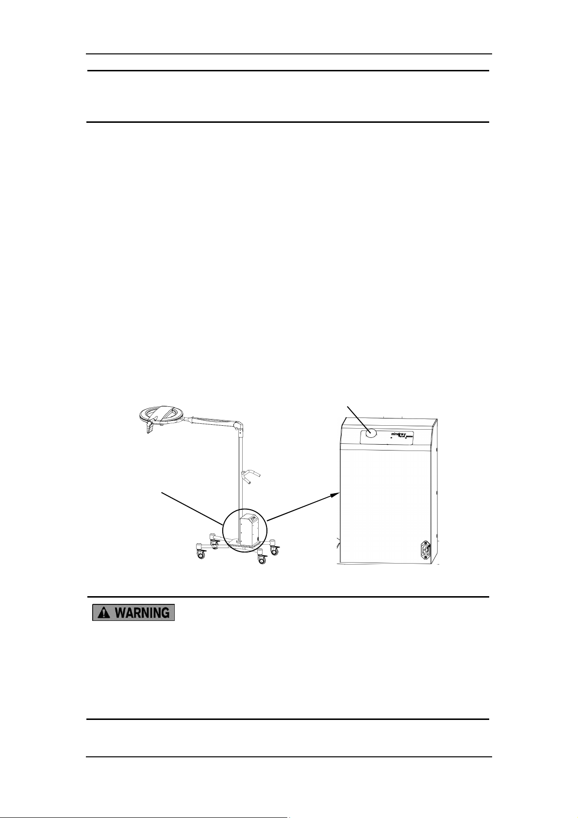
Main switch
Power module
Figure 2-1 HyLED 760M/730M
Be sure to lock the castors before using the HyLED 760M/730M light.
Otherwise, the mobile light may slip and cause personal injury and/or
property damage.
Do not lean on the spring arm. Otherwise, the lighthead may swing and
cause personal injury and/or property damage.
2-2
Page 21
Daily Operations
2.1.4 Warning Label (HyLED 760M/730M)
A
B
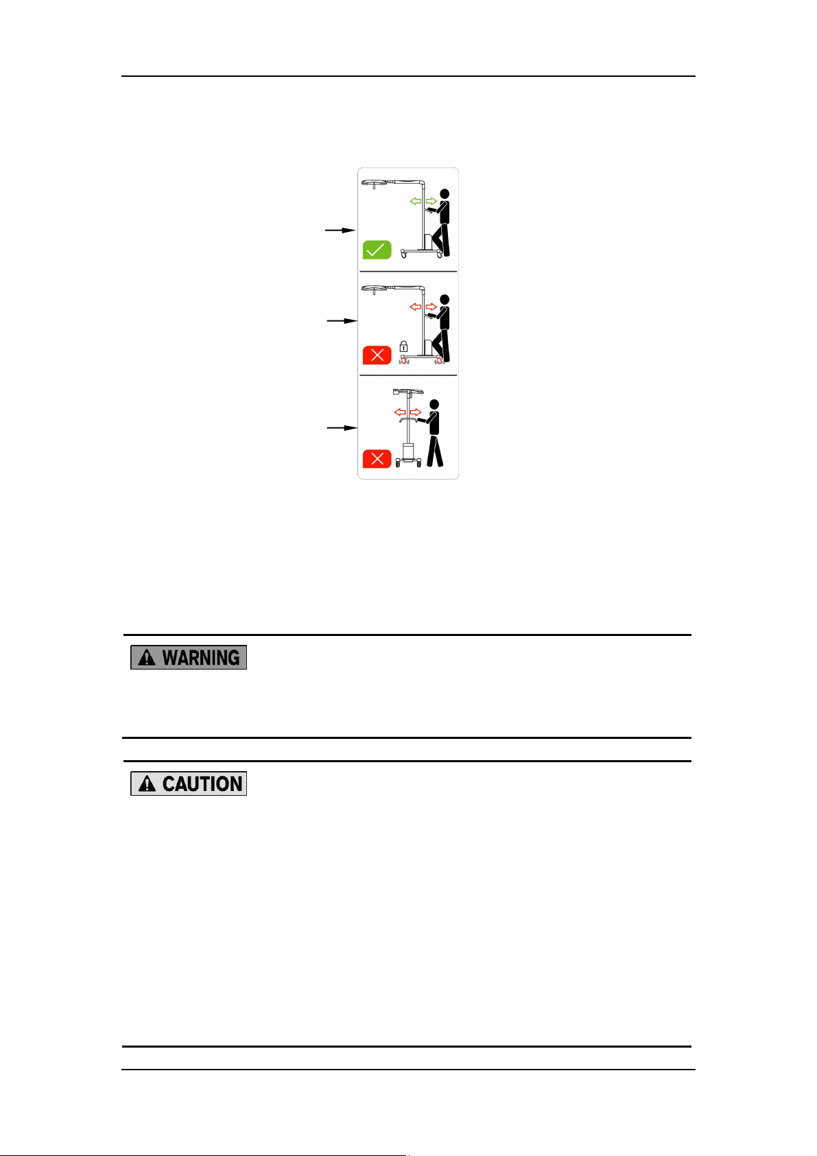
C
Figure 2-2 Warning label for HyLED 760M/730M
The warning labels mean:
A: The correct way to move the surgical light.
B: Do not move the mobile surgical light when the castors are locked.
C: Do not try to move the mobile surgical light by exerting force from either side.
Be sure to tidy the power cable in the process of moving and in the desired
position. Otherwise, it may cause stumbling.
Do not move the mobile surgical light when the castors are locked.
Be sure to move the mobile surgical light only by the handle on the pole.
Do not stand on the base.
Be sure to move the mobile surgical light on smooth ground. Make sure the
moving speed is not over the walking speed. Otherwise, it may cause
personal injury and device damage.
Do not use the sterilizable handle to move the mobile surgical light.
Be sure to lock the castors when the mobile surgical light is in the desired
position.
2-3
Page 22
Daily Operations
2.2 Using Lighthead
2.2.1 General
You can:
1. Use the sterilizable handle to adjust the lighthead position.
2. Use the control panel/touch control panel/wall control panel/touch wall control panel to
operate the light.
Do not direct the light source towards human eyes. Otherwise, it may cause
personal injury.
Do not lean on the spring arm.
Be sure to adjust the illuminance level based on the needs of the operation.
Note that there is a risk of too much heat in the operating field by
overlapping the light fields of several lightheads, in which case the surgical
light system may exceed an total irradiance of 1 000 W/m².
2.2.2 Installing/Removing Sterilizable Handle
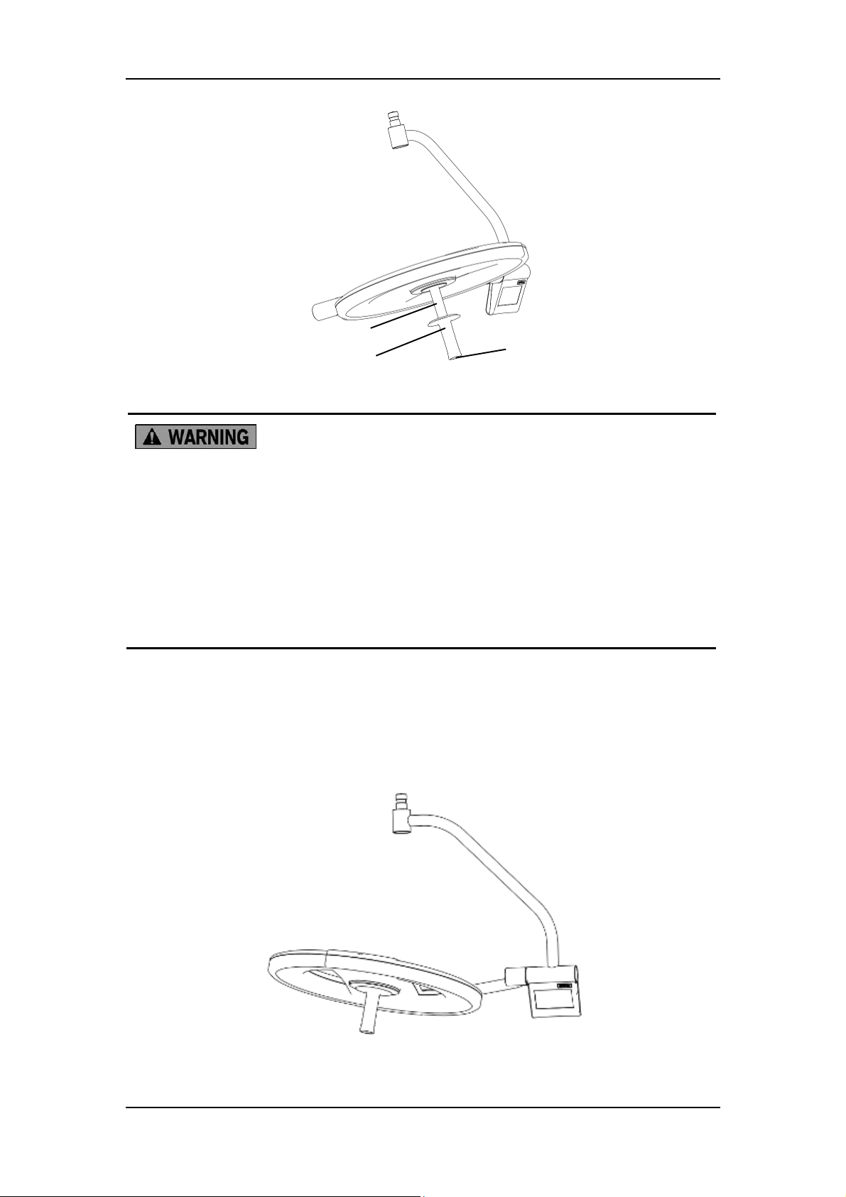
To install the sterilizable handle:
1. Slide the sterilizable handle onto the central handle of the lighthead.
2. Push the sterilizable handle upward until it clicks.
3. Pull the sterilizable handle downward to make sure it is not loose.
To remove the sterilizable handle:
1. Grab the lighthead with one hand.
2. Grab the handle with the other hand. Press the button at the bottom and pull the handle
downward.
2-4
Page 23
Daily Operations
Central handle
Button
Sterilizable handle
Figure 2-3 How to install/remove the sterilizable handle
Be sure to sterilize the sterilizable handle each time before using it.
The sterilizable handle is to be used by sterile personnel only.
If the sterilizable handle falls off during the operation, it might infect the
operative wound. Make sure the sterilizable handle is properly and reliably
installed.
Sterile disposable handles are not recommended. They may fall off during
the operation and infect the operative wound.
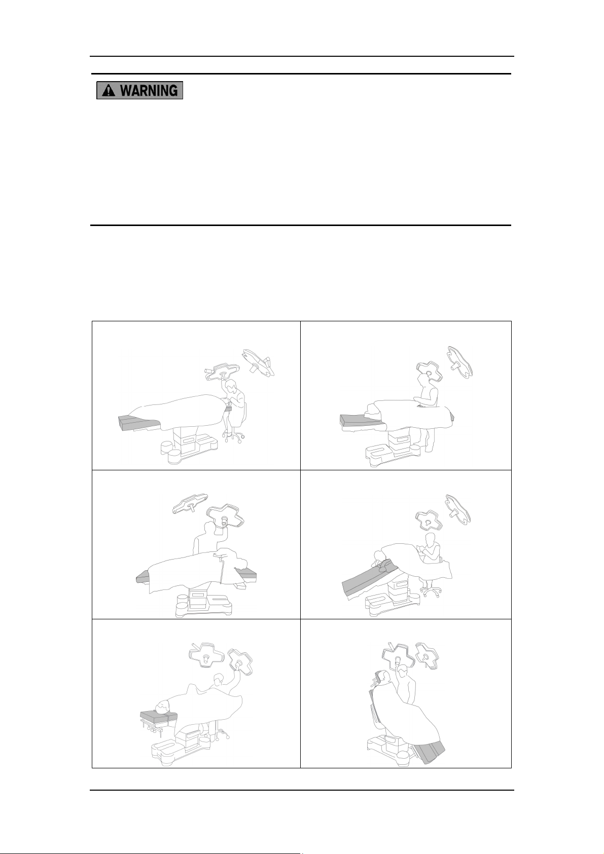
2.2.3 Adjusting Lighthead Position
You (sterile personnel) can use the sterilizable handle to move the lighthead.
Figure 2-4 Adjusting the lighthead position
2-5
Page 24
Daily Operations
Exercise caution when adjusting the lighthead position. Do not pull the
spring arms beyond their limits.
To avoid the risk of infection, only the sterile personnel may touch the
sterilizable handle during the operations.
Sterile personnel can only use the sterilizable handle to move the lighthead.
The sterilizable handle must be sterilized each time before use.
It is recommended that the lighthead be prepositioned prior to any procedure to minimize
subsequent handling. The table below (using only HyLED 9700/9500 lightheads as an
example) shows several prepositioning examples in terms of surgical positions.
Table 2-1 Prepositioning examples
Supine position:
Lateral position:
Prone position:
Rectal position:
Lithotomy position:
Seated position:
2-6
Page 25
Daily Operations
3 5
4 6 7
1 2 3 5
4 6 7
2.2.4 Using Control Panel
14
13
8
1
2
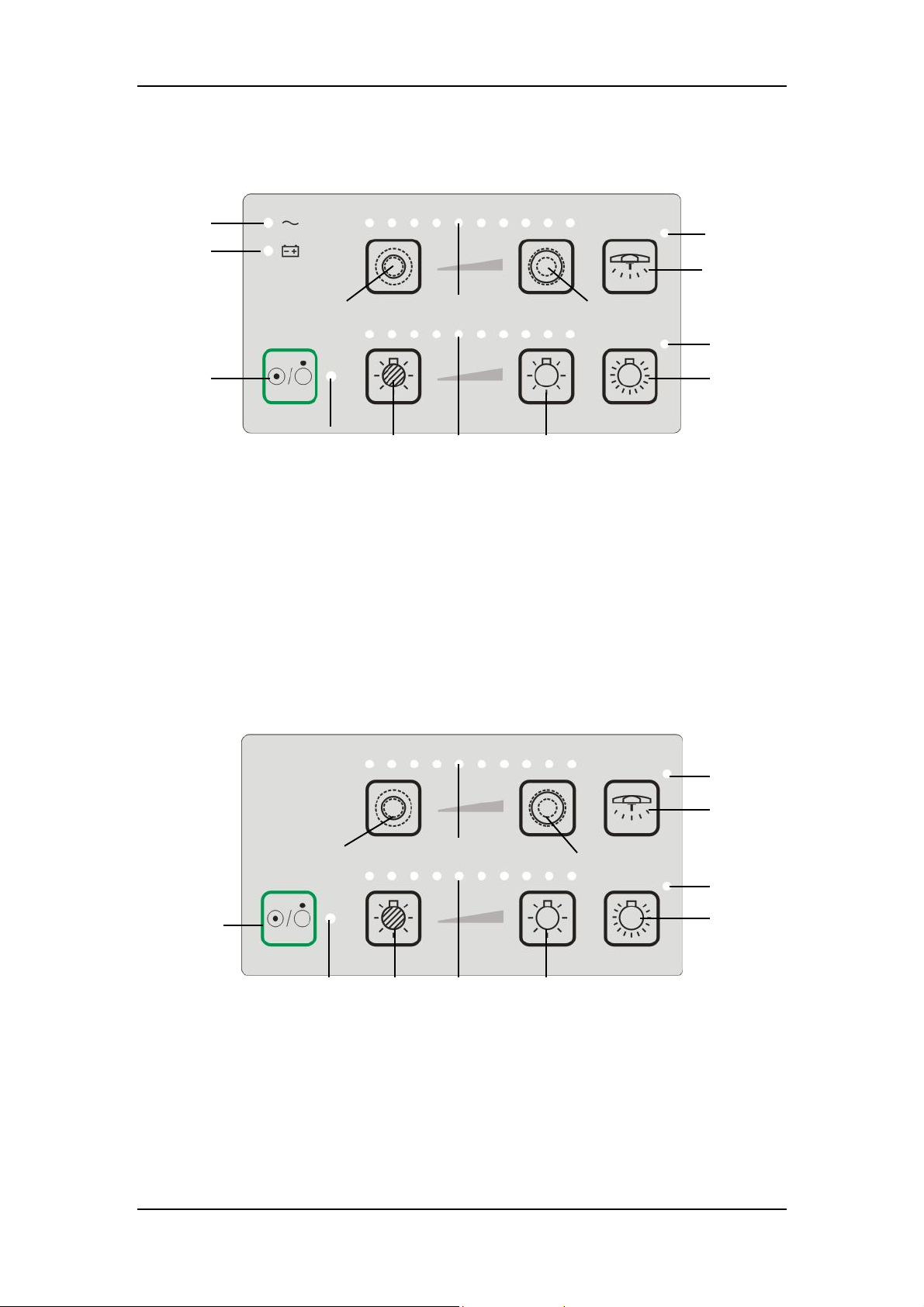
Figure 2-5 HyLED 760/730 control panel (optional)
1 Power Switch 2 Status Indicator
3 Illuminance Down 4 Illuminance Indicator
5 llluminance Up 6 Full Illuminance
7 Full Illuminance Indicator 8 Light Field Size Down
9 Light Field Size Indicator 10 Light Field Size Up
11 MIS Lighting
13 Backup Battery Indicator
9
12 MIS Lighting Indicator
14 AC Indicator
10
12
11
8
Figure 2-6 HyLED 760M/730M control panel (optional)
1 Power Switch 2 Status Indicator
3 Illuminance Down 4 Illuminance Indicator
5 llluminance Up 6 Full Illuminance
7 Full Illuminance Indicator 8 Light Field Size Down
9 Light Field Size Indicator 10 Light Field Size Up
11 MIS Lighting 12 MIS Lighting Indicator
9
10
12
11
2-7
Page 26
Daily Operations
2 3 1 2 3
1
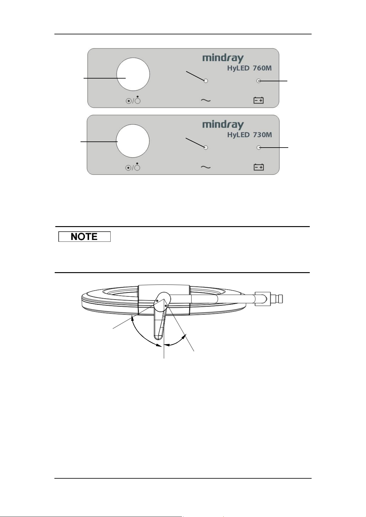
Figure 2-7 HyLED 760M/730M power module panel
1 Main Switch 2 AC Indicator
3 Battery Indicator
For the lighthead with the LCH spring arm, the control panel can be rotated
when it is difficult to operate.
About 60°
About 30°
Figure 2-8 Rotatable control panel
You can:
1. Press the “Power Switch” button to turn on/off the lighthead.
2. Press the “Illuminance Up”/“Illuminance Down” button to adjust the lighthead’s illuminance.
The illuminance is 10-level adjustable.
3. Press the “Full Illuminance” button to enter the full illuminance mode.
4. Check the illuminance level by the illuminance indicator.
2-8
Page 27
Daily Operations
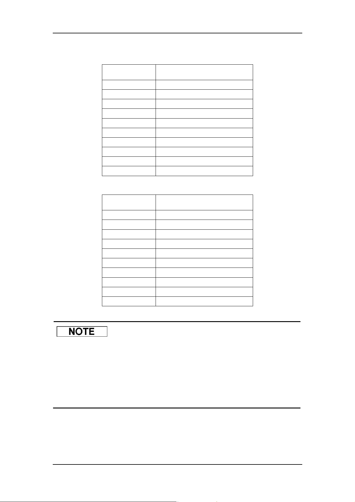
Table 2-2 Illuminance levels under normal lighting mode
Level Illuminance (ratio)
1 About 20%
2 About 30%
3 About 35%
4 About 45%
5 About 55%
6 About 60%
7 About 70%
8 About 80%
9 About 90%
10 About 100%
Table 2-3 Illuminance levels under full illuminance mode
Level Illuminance (ratio)
1 About 82%
2 About 84%
3 About 86%
4 About 88%
5 About 90%
6 About 92%
7 About 94%
8 About 96%
9 About 98%
10 About 100%
100% illuminance under the full illuminance mode is the maximum
illuminance.
For the HyLED 760/760M lighthead, 100% illuminance under the normal
lighting mode is about 120,000 lx.
For the HyLED 730/730M lighthead, 100% illuminance under the normal
lighting mode is about 100,000 lx.
5. Press the “Light Field Size Up”/“Light Field Size Down” button to adjust the lighthead's
light field size. The light field size is 10-level adjustable.
6. Check the light field level by the light field size indicator.
2-9
Page 28
Daily Operations
7. Press the “MIS Lighting” button to enter the MIS lighting mode. In this mode, the
illuminance is only about 5% of the maximum illuminance, which is sufficient for ambient
lighting for Minimally Invasive Surgeries.
8. Check the light state by the indicators. See the table below for details.
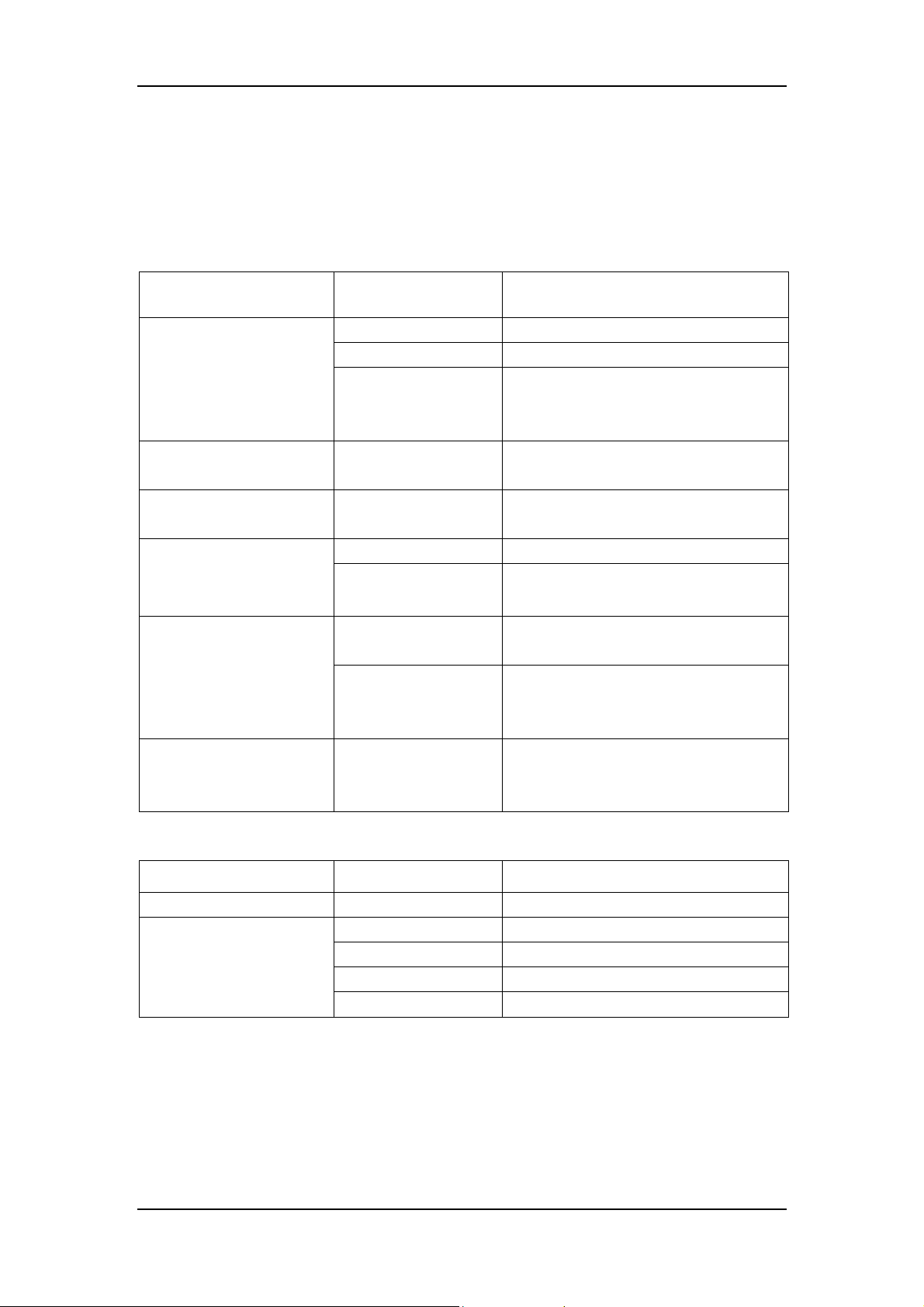
Table 2-4 Indicator definitions of lighthead panel
Indicator State Definition
Green Everything is normal.
Red and flashing Voltage to the lighthead is too low.
Status Indicator
Orange and flashing
Full illuminance indicator Green
MIS lighting indicator Green
Green The lighthead is AC powered.
AC indicator
Off The lighthead is not AC powered.
Communication error of the surgical
light system (Not applicable to HyLED
760M/730M).
The lighthead is in the full illuminance
mode.
The lighthead is in the MIS lighting
mode.
Green
Backup battery indicator
Off
Status
indicator&illuminance
indicator
Table 2-5 Indicator definitions of power module panel
Indicator State Definition
AC indicator Green The lighthead is AC powered.
Battery indicator
The former red and
flashing, and the
latter flashing
Orange The batteries are charging.
Off Charging is done.
Green The batteries function normally.
Red The batteries are low.
The surgical light is working on the
backup batteries.
The surgical light is not working on the
backup batteries or not configured with
backup batteries.
There is communication error inside
the lighthead.
2-10
Page 29
Daily Operations
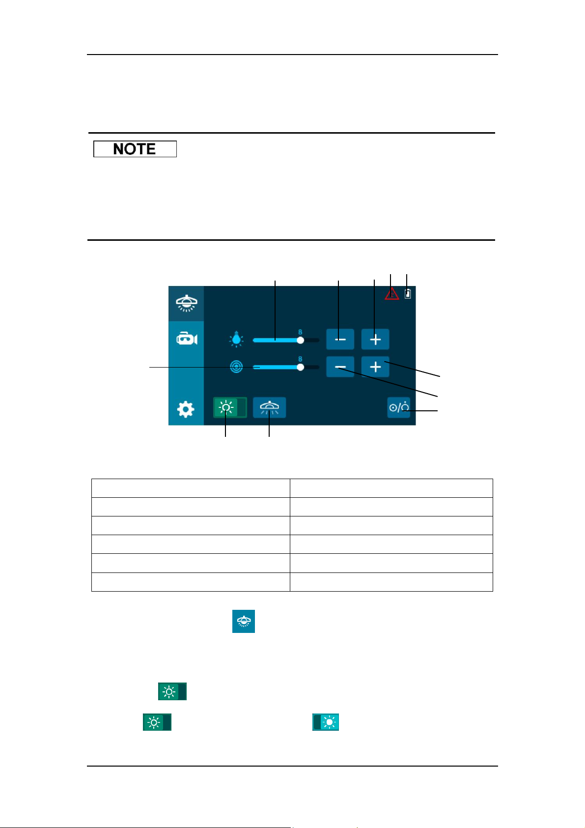
5 7 6 8 9 2 3 4 10
2.2.5 Using Touch Control Panel
During the power-on process, do not press and hold the touch control
panel. Otherwise, you may miscalibrate the touch control panel.
For the lighthead with the LCH spring arm, the touch control panel can be
rotated when it is difficult to operate.
2.2.5.1Light Control
11
1
Figure 2-9 Common functions for light control
1 Power Switch 2 Illuminance Indicator
3 Illuminance Down 4 Illuminance Up
5 Light Field Size Indicator 6 Light Field Size Down
7 Light Field Size Up 8 Normal Lighting/Full Illuminance
9 MIS Lighting 10 Error Indicator
11 Backup Battery Indicator
Press the “Light Control” button ( ) to access the “Common functions” screen for the light
control. At the “Common functions” screen, you can:
1. Press the “Power Switch” button to turn on/off the lighthead.
2. This icon “ ” means the lighthead is under the normal lighting mode. Press the
button “ ”, and the icon will change into “ ”, which means the lighthead enters
the full illuminance mode.
2-11
Page 30
Daily Operations
3. Press the “Illuminance Up”/“Illuminance Down” button to adjust the lighthead’s illuminance.
The illuminance is 10-level adjustable (See 2.2.4 Table 2-2 and Table 2-3 for illuminance
levels).
4. Check the illuminance level by the illuminance indicator.
5. Press the "Light Field Size Up”/“Light Field Size Down” button to adjust the lighthead's
light field size. The light field size is 10-level adjustable.
6. Check the light field level by the light field size indicator.
7. Press the “MIS Lighting” button to enter the MIS lighting mode. In this mode, the
illuminance is only about 5% of the maximum illuminance, which is sufficient for ambient
lighting for Minimally Invasive Surgeries.
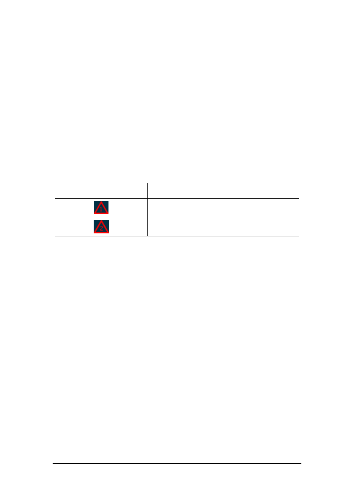
8. Check the error of the surgical light.
Table 2-6 Details of the error indicators
Error Indicator Definition
9. Check if the surgical light is working on the batteries (Backup Battery Indicator on).
Communication error inside the lighthead
Communication error of the surgical light system (Not
applicable to HyLED 760M/730M)
2-12
Page 31
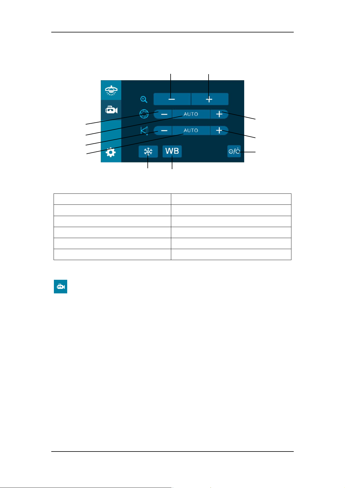
7 5 6
3
2.2.5.2Camera Control
Daily Operations
4
8
10 11
Figure 2-10 Common functions of the camera
1 Power Switch 2 Zoom Out
3 Zoom In 4 Iris Down
5 Auto Iris 6 Iris Up
7 Focus Near 8 Auto Focus
2
9
1
9 Focus Far 10 Freeze/Unfreeze
11 White Balance (WB)
If the surgical light system is configured with a camera, press the “Camera Control” button
( ) to access the “Common functions” screen for the camera. At the “Common functions”
screen, you can:
1. Press the “Power Switch” button to turn on/off the camera.
2. Press the “Zoom In”/“Zoom Out” button to magnify/minify the image.
3. Press the “Iris Up”/“Iris Down” button to adjust the iris size.
4. Press the “Auto Iris” button to automatically adjust the iris size.
5. Press the “Focus Near”/“Focus Far” button to adjust the camera focus.
6. Press the “Auto Focus” button to automatically adjust the camera focus.
7. Press the “Freeze/Unfreeze” button to freeze/unfreeze the image.
8. Press the “WB” button to select different white-balance modes and obtain the proper color.
Three modes are available: Indoor, Outdoor and Auto WB. Press the “WB” button to
toggle among the modes.
2-13
Page 32
Daily Operations
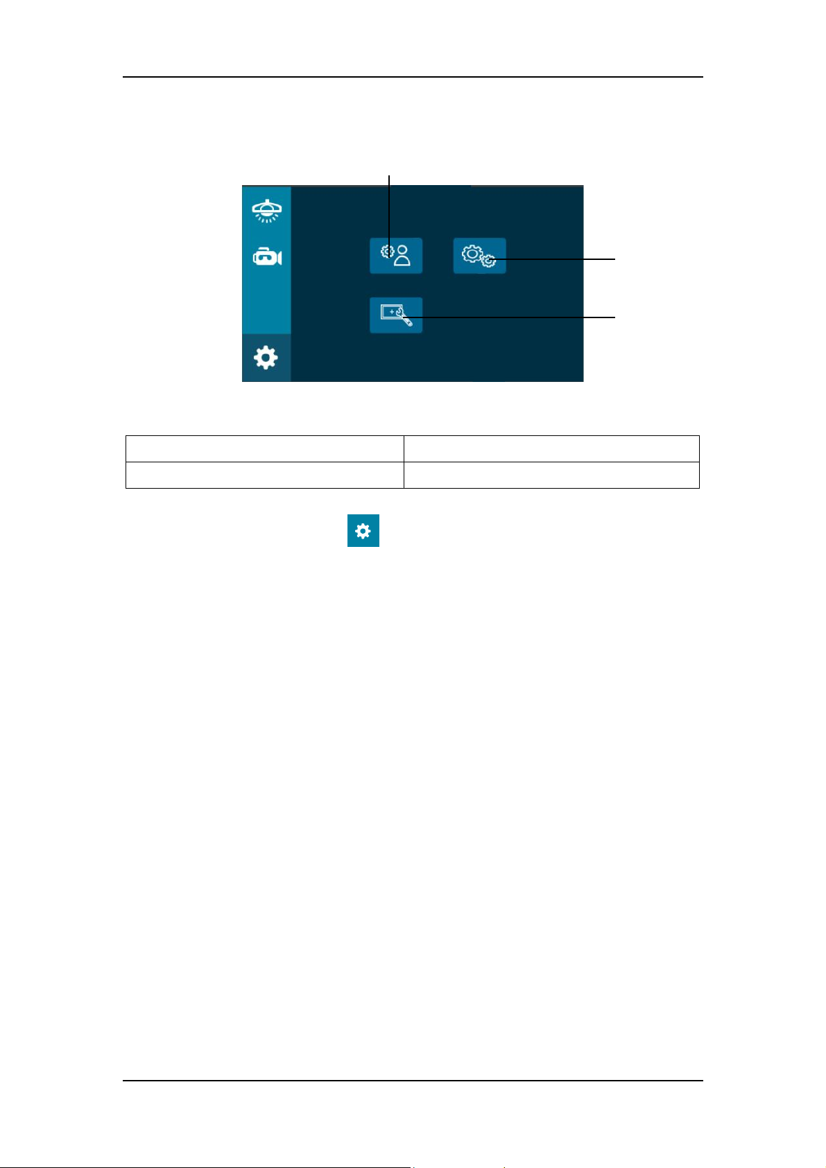
1 2
2.2.5.3Setting Control
Figure 2-11 Common functions for the setting control
1 Service Settings 2 Factory Settings
3
3 Calibration
Press the “Setting Control” button ( ) to access the “Common functions” screen for the
setting control. At the “Common functions” screen, you can:
1. The “Service Settings” button is only for the service engineer use and the “Factory
Settings” button is only for factory use.
2. Press the “Calibration” button to calibrate the touch screen. See 3.4 for details.
2-14
Page 33
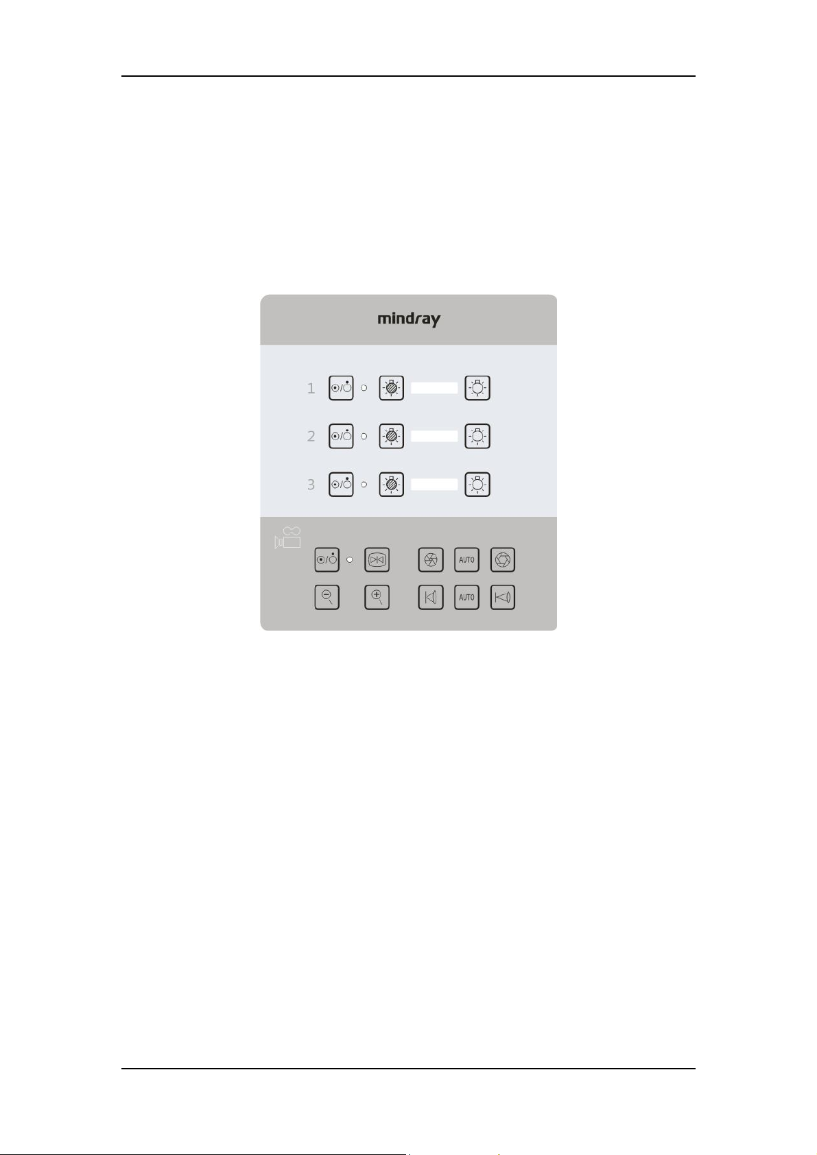
Daily Operations
7
2.2.6 Using Wall Control Panel (optional)
The wall control panel can control both the lightheads (except for HyLED 760M/730M) and the
camera. The following figure takes the three-swivel-arm light as an example. The three-group
buttons on the upper part are used to control the three lightheads respectively, and the buttons
on the bottom are for the camera. See 2.2.4 and 2.2.5 for how to use the control panel.
1
6 8
12
Figure 2-12 Wall control panel
1 Power Switch (surgical light) 2 Status Indicator (surgical light)
3 Illuminance Down 4 Illuminance Indicator
5 Illuminance Up 6 Power Switch (camera)
7 Status Indicator (camera) 8 Freeze/Unfreeze
9 Iris Down 10 Auto Iris
11 Iris Up 12 Zoom Out
13 Zoom In 14 Focus Near
15 Auto Focus 16 Focus Far
3
2
13 14 16 15
4
9 11
5
10
2-15
Page 34
Daily Operations
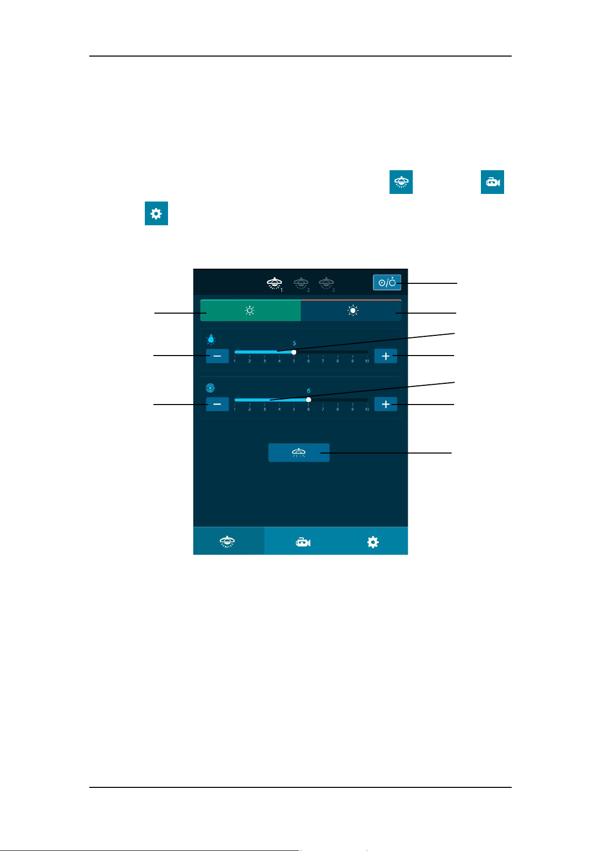
2.2.7 Using Touch Wall Control Panel (optional)
The surgical light system (except for HyLED 760M/730M) can be controlled by the touch wall
control panel. The following figures take the three-swivel-arm light as an example. The buttons
on the bottom is to access the function controls of the lighthead ( ) and camera ( ).
The button ( ) is only for factory use. See 2.2.5.1 and 2.2.5.2 for how to use the touch wall
control panel.
1
2
4
7
Figure 2-13 Touch wall control panel (light control)
1 Power Switch (surgical light) 2 Normal Lighting
3 Full Illuminance 4 Illuminance Down
5 Illuminance Indicator 6 Illuminance Up
7 Light Field Size Down 8 Light Field Size Indicator
9 Light Field Size Up 10 MIS Lighting
3
5
6
8
9
10
2-16
Page 35
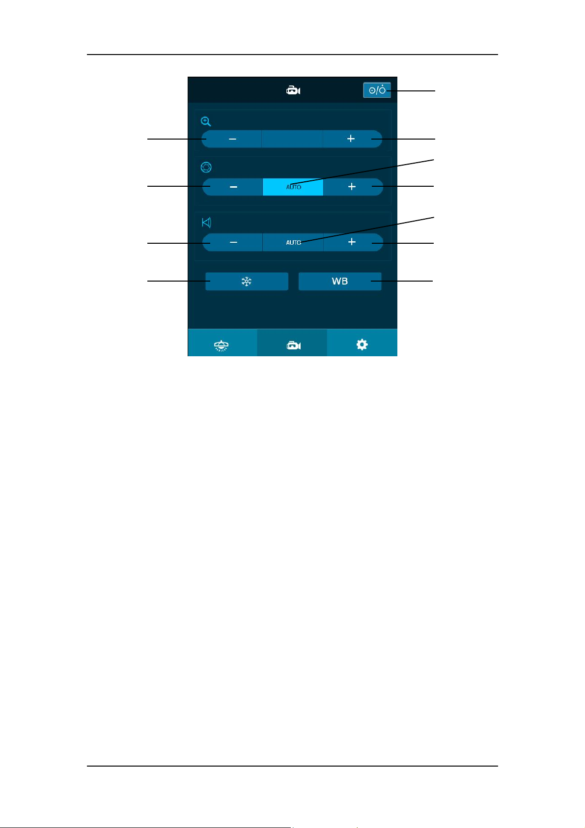
Daily Operations
4
1
2
10
Figure 2-14 Touch wall control panel (camera control)
1 Power Switch (camera) 2 Zoom Out
3 Zoom In 4 Iris Down
5 Auto Iris 6 Iris Up
7 Focus Near 8 Auto Focus
9 Focus Far 10 Freeze/Unfreeze
11 White Balance (WB)
3
5
6
8
9 7
11
2-17
Page 36
Daily Operations
2.3 Using Carrier-arm Camera (optional)
2.3.1 General
You can:
1. Use the sterilizable handle to adjust the camera position.
2. Use the control panel/wall control panel/touch wall control panel/infrared remote control to
adjust the camera.
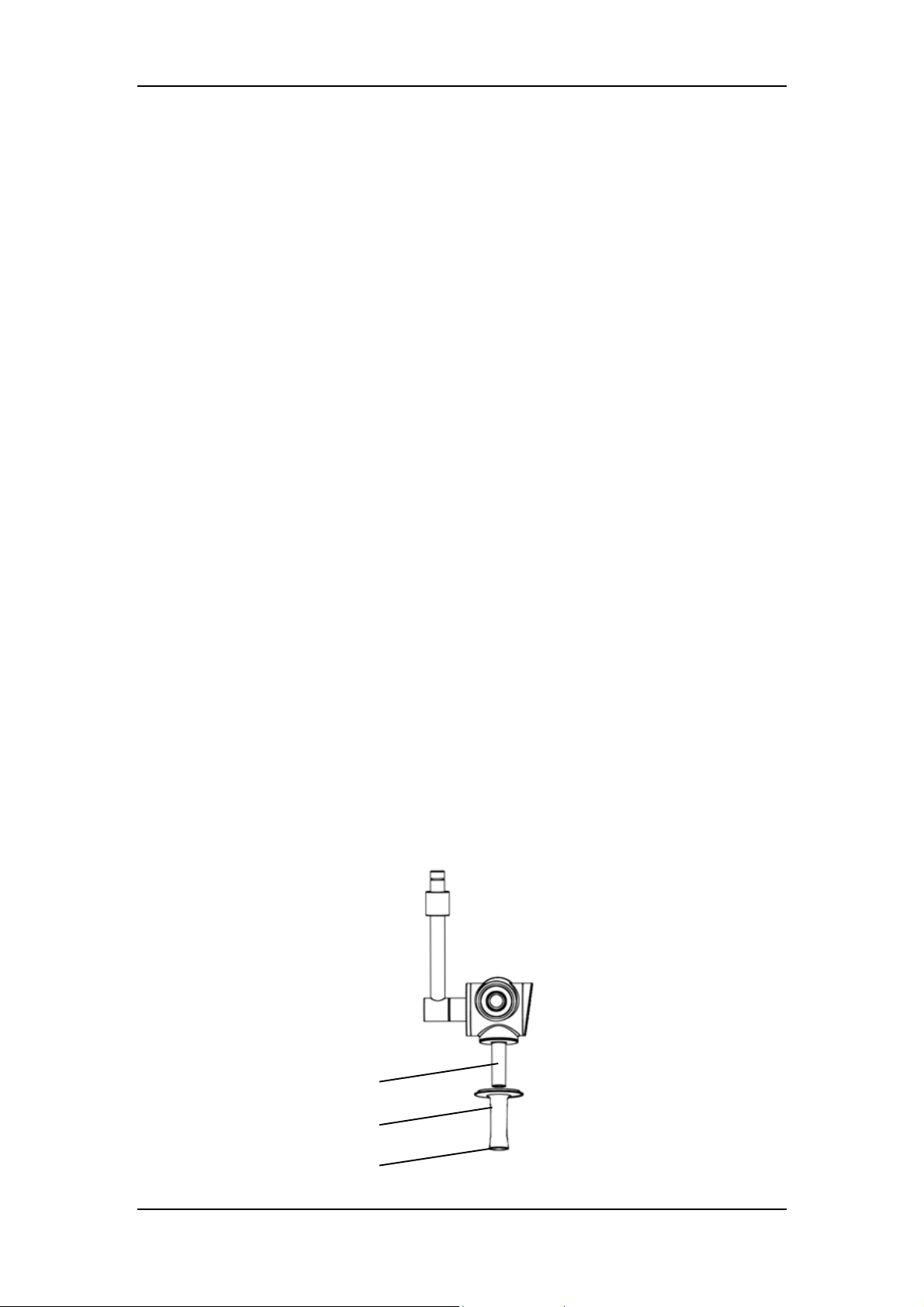
2.3.2 Installing/Removing Sterilizable Handle of Carrier-arm
Camera
To install the sterilizable handle of the carrier-arm camera:
1. Slide the sterilizable handle onto the carrier-arm camera.
2. Push the sterilizable handle upward until it clicks.
3. Pull the sterilizable handle downward to make sure it is not loose.
To remove the sterilizable handle:
1. Grab the camera with one hand.
2. Grab the handle with the other hand. Press the button at the bottom and pull the handle
downward.
Carrier-arm camera
Sterilizable handle
Button
Figure 2-15 How to install/remove the sterilizable handle of the carrier-arm camera
2-18
Page 37
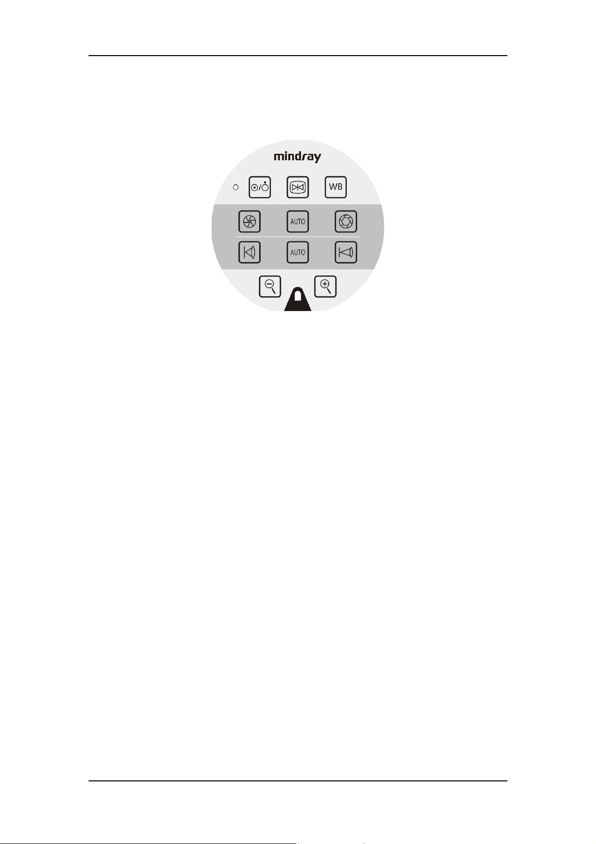
2.3.3 Using Control Panel
2 1 3 4 5 6 7 8 9
Daily Operations
10
11
Figure 2-16 Control panel
1 Status Indicator 2 Power Switch
3 Freeze/Unfreeze 4 White Balance (WB)
5 Iris Down 6 Auto Iris
7 Iris Up 8 Focus Near
9 Auto Focus 10 Focus Far
11 Zoom Out 12 Zoom In
13 Infrared Signal Receiver
You can:
1. Push the “Power Switch” button to turn on/off the camera.
2. Push the “Freeze/Unfreeze” button to freeze/unfreeze image.
3. Push the “Iris Up”/“Iris Down” button to adjust the iris size.
4. Push the “Auto Iris” button to automatically adjust the iris size.
13
12
5. Push the “Zoom In”/“Zoom Out” button to magnify/minify the image.
6. Push the “Focus Near”/“Focus Far” button to adjust the camera focus.
7. Push the “Auto Focus” button to automatically adjust the camera focus.
8. Push the “WB” button to select different white-balance modes and obtain the proper color.
Three modes are available: Indoor, Outdoor and Auto WB. Press the “WB” button to
toggle among the modes.
2-19
Page 38
Daily Operations
2
2.3.4 Using Touch Control Panel/Wall Control Panel/Touch
Wall Control Panel (optional)
See 2.2.5.2, 2.2.6 and 2.2.7 for details.
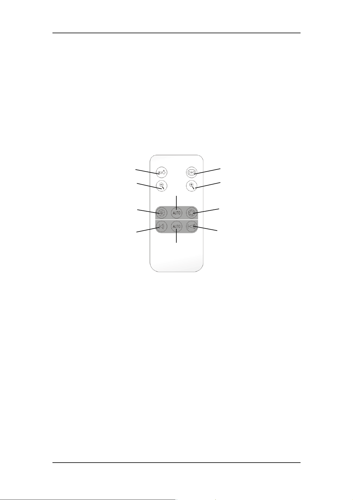
2.3.5 Using Infrared Remote Control (optional)
1
3
6
5
8
9
Figure 2-17 Infrared remote control
1 Power Switch 2 Freeze/Unfreeze
3 Zoom Out 4 Zoom In
5 Iris Down 6 Auto Iris
7 Iris Up 8 Focus Near
9 Auto Focus 10 Focus Far
4
7
10
Hold the infrared remote control toward the infrared signal receiver of the camera control panel.
You can:
1. Push the “Power Switch” button to turn on/off the camera.
2. Push the “Freeze/Unfreeze” button to freeze/unfreeze image.
3. Push the “Iris Up”/“Iris Down” button to adjust the iris size.
4. Push the “Auto Iris” button to automatically adjust the iris size.
5. Push the “Zoom In”/“Zoom Out” button to magnify/minify the image.
6. Push the “Focus Near”/“Focus Far” button to adjust the camera focus.
7. Push the “Auto Focus” button to automatically adjust the camera focus.
2-20
Page 39

Daily Operations
If the infrared signal is interrupted by some object, you should remove it and
repush the button.
2-21
Page 40
Daily Operations
2.4 Using Rotatable Integrated Camera (optional)
2.4.1 General
The HyLED 760 lighthead can be configured with a rotatable integrated camera. You can:
1. Use the sterilizable handle to adjust the position of the lighthead configured with the
rotatable integrated camera.
2. Turn the sterilizable handle to rotate the camera if you find the displayed image is
upside-down.
3. Use the touch control panel/wall control panel/touch wall control panel/infrared remote
control to operate the camera.
2.4.2 Installing Rotatable Integrated Camera
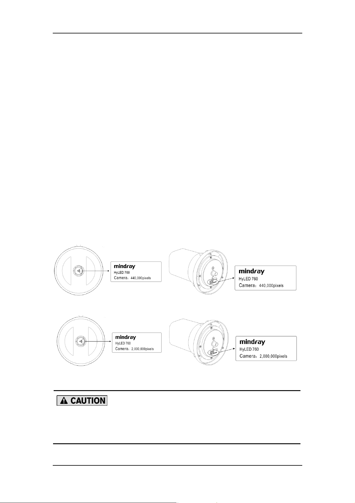
1. Check if the label on the lighthead is consistent with the label on the camera.
Figure 2-18 SD camera labels
Figure 2-19 HD camera labels
Two types (standard definition and high definition) of the integrated
cameras are available. Make sure the label on the lighthead is consistent
with that on the camera.
2-22
Page 41
Daily Operations
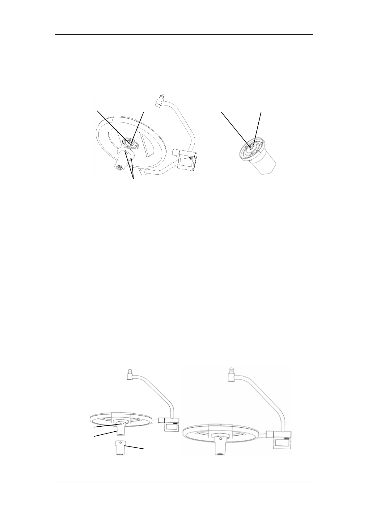
Button
2. Align the pin on the camera with the hole on the lighthead, and the connector with the
socket, and then connect the camera to the lighthead.
3. Tighten the knurled screws.
Hole
Socket
Pin Connector
Knurled screws
Figure 2-20 How to install the rotatable integrated camera
2.4.3 Installing/Removing Sterilizable Handle of Rotatable
Integrated Camera
To install the sterilizable handle of the camera:
1. Slide the sterilizable handle onto the camera until it is fully engaged with the button.
2. Pull the sterilizable handle downward to make sure it is not loose.
To remove the sterilizable handle:
1. Grab the lighthead with one hand.
2. Grab the handle with the other hand. Press the button as shown in the figure below and
pull the handle downward.
Integrated
camera
Figure 2-21 How to install/remove sterilizable handle of the rotatable integrated camera
Sterilizable handle
2-23
Page 42
Daily Operations
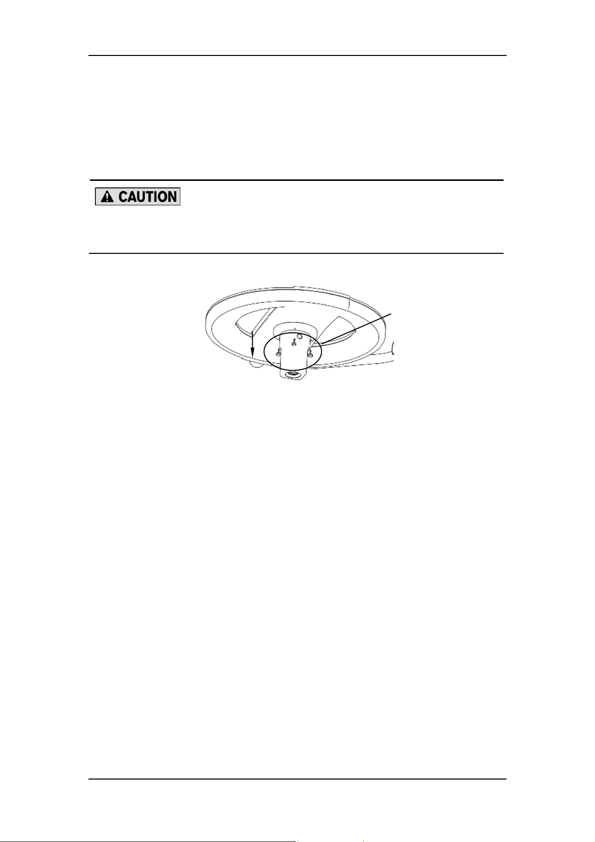
2.4.4 Removing Rotatable Integrated Camera
1. Loosen the three knurled screws.
2. Carefully pull out the camera.
Do not rotate the camera before pulling it out. Otherwise, the connector may
be damaged.
Knurled screws
Figure 2-22 How to remove the rotatable integrated camera
2.4.5 Using Touch Control Panel
See 2.2.5.2 for details.
2.4.6 Using Wall Control Panel/Touch Wall Control Panel
(optional)
See 2.2.6 and 2.2.7 for details.
2.4.7 Using Infrared Remote Control (optional)
To control the integrated camera, be sure to hold the infrared remote control toward the
infrared signal receiver of the swivel arm assembly bottom. See 2.3.5 for detailed instruction.
2-24
Page 43
Daily Operations
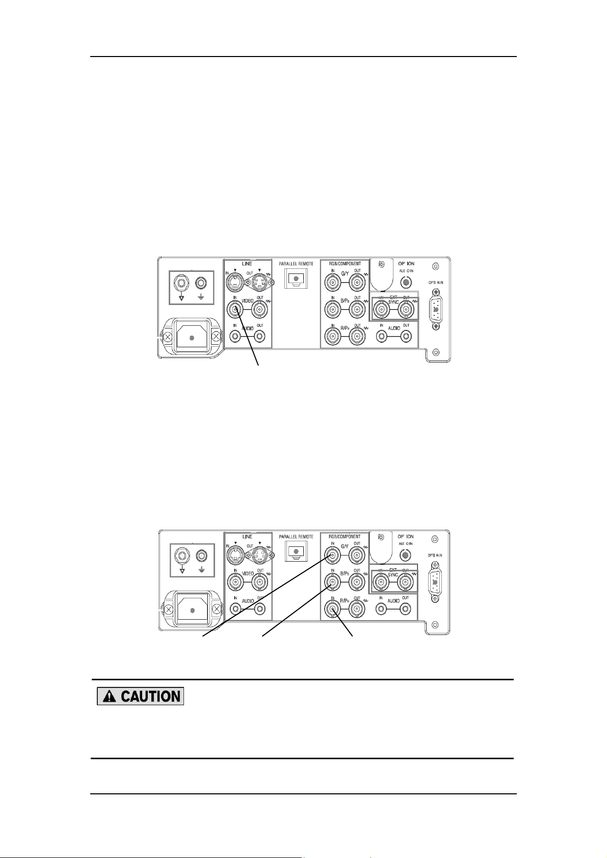
Green jack
2.5 Using Display (optional)
2.5.1 For SD Camera
The SD camera outputs a composite signal that is usually connected to the yellow jack of a
display, as the figure below suggests. For more details, refer to the instructions for use of the
display.
Yellow jack
Figure 2-23 Connection for SD camera
2.5.2 For HD Camera
The HD camera outputs a component signal that is usually connected to the Y/Pb/Pr jacks of
the display, as the figure below shows. For more details, refer to the instructions for use of the
display.
Blue jack
Figure 2-24 Y/Pb/Pr connections
Red jack
Make sure your local mains supply is suitable for the display.
Make sure the display complies with the local regulations.
2-25
Page 44
Daily Operations
For certain displays, RGB and component signals may share the same input
interface. Be sure to select the component signal from the menu.
Do not let the display automatically scan the signal source at every start.
Otherwise, you may need to reset the input source. Refer to the instruction
for use of the display for how to disable the auto scanning function.
It is recommended that a medical display be used due to uncertain
interference during the surgery.
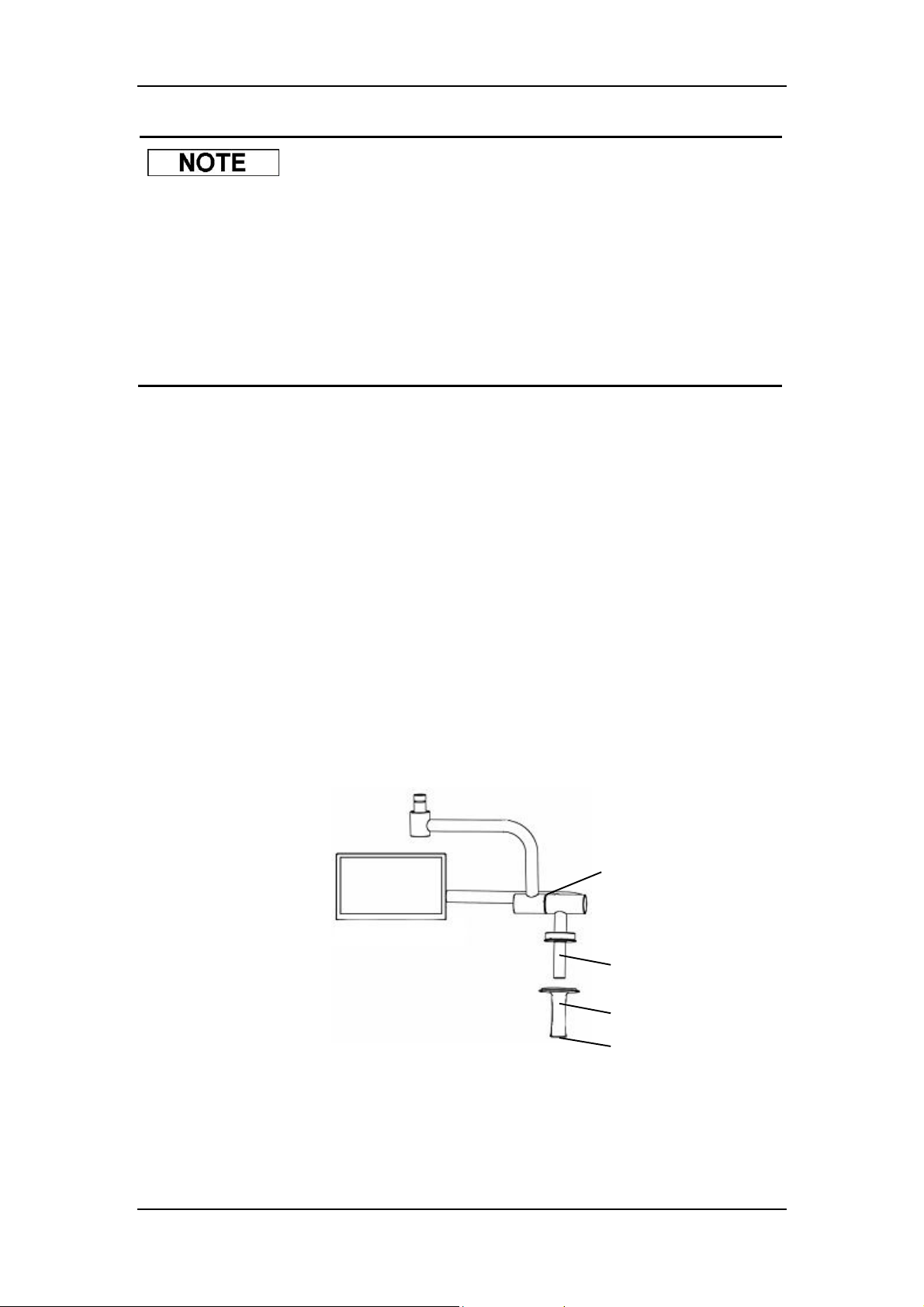
2.5.3 Installing/Removing Sterilizable Handle of Display
To install the sterilizable handle of the display:
1. Slide the sterilizable handle onto the central handle.
2. Push the sterilizable handle upward until it clicks.
3. Pull the sterilizable handle downward to make sure it is not loose.
To remove the sterilizable handle:
1. Grab the swivel arm with one hand.
2. Grab the handle with the other hand. Press the button at the bottom and pull the handle
downward.
Swivel arm for the display
Central handle
Sterilizable handle
Figure 2-25 How to install/remove the sterilizable handle of the display
2-26
Button
Page 45
3.1 Maintenance Period
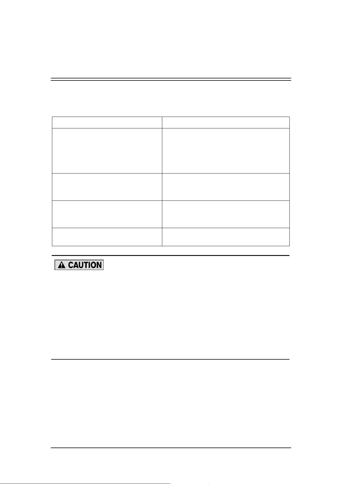
Item Period
Function and illuminance checks
Cable/wire checks
Complete system checks
Backup battery checks
3 Maintenance
Functions and illuminance should be checked
each time before use.
Complete functional and performance checks
should be conducted every 2 years by
personnel authorized by Nanjing Mindray.
Cable/wire checks should be conducted every 6
years by personnel authorized by Nanjing
Mindray.
Complete system checks should be conducted
every 10 years by personnel authorized by
Nanjing Mindray.
The switchover to the backup batteries should
be tested every month. See 3.3 for details.
Disassembly of certain components can affect operation and safety (e.g.
when servicing the electrical power supply, when servicing the swivel arm
assembly and the spring arms).
The shelf life of the surgical light is 10 years.
The service life of the surgical light is 10 years. Complete system checks
and replacement should be conducted every 10 years by personnel
authorized by Nanjing Mindray.
The average service life of the LED is 60,000 hours.
3-1
Page 46

Maintenance
3.2 Cleaning/Disinfection
Be sure to follow the related national hygiene and disinfection regulations to
carry out cleaning and disinfection procedures.
3.2.1 Maintaining Lighthead Exterior
The lighthead has a high-quality surface that can be cleaned/disinfected with conventional
cleaning/disinfection agents, except for strong acid, alcohol and chlorinated hydrocarbons.
3.2.1.1Recommended Cleaning Agents and Disinfectants
Mildly alkaline (10% soap solution; 40°C/104°F maximum)
Aldehydes (2%)
Warm water (40°C/104°F maximum)
3.2.1.2Forbidden Cleaning Agents and Disinfectants
Disinfectants containing alcohol
Halogen releasing compounds
Chlorinated hydrocarbons
Strong organic acid
Oxygen releasing compounds
3.2.1.3Maintenance Period
The lighthead should be cleaned/disinfected each time after use and at least once a week.
3.2.1.4Cleaning
1. Switch off the light, and wait until it cools down completely.
2. Use a piece of disposable lint-free cloth to wipe dust off the lighthead.
3. Use a piece of lint-free cloth moistened with detergent to wipe the exterior of the
lighthead.
4. Use a piece of disposable lint-free cloth moistened with water to clean the exterior of the
lighthead, and then wipe it dry.
3-2
Page 47
Maintenance
3.2.1.5Disinfection
1. Use a piece of lint-free cloth moistened with disinfectant to wipe the exterior of the
lighthead.
2. Use a piece of disposable lint-free cloth moistened with water to clean the exterior of the
lighthead, and then wipe it dry.
The above-mentioned method applies to the following parts:
exterior of the lamp housing hood
glass
exterior of the light arms (both swivel arms and spring arms)
exterior of the control panel
ceiling cover
camera
display
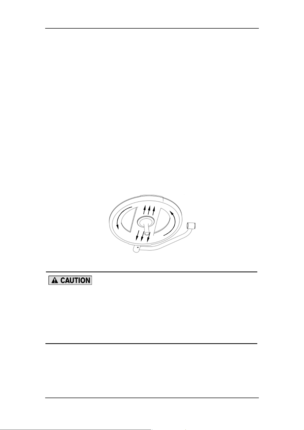
Figure 3-1 How to clean the glass
When cleaning/disinfecting the lighthead glass, be sure to wipe from the
inside to the outside around the sterilizable handle and then wipe along the
radius, as Figure 3-1 shows. Do not wipe back and forth or in circles.
Otherwise, the glass surface may be damaged.
The glass should be cleaned/disinfected each time after use and at least
once a week.
3-3
Page 48

Maintenance
3.2.2 Maintaining Touch Screen (optional)
3.2.2.1Maintenance Period
The touch screen should be cleaned/disinfected each time after use and at least once a week.
3.2.2.2Cleaning
1. Switch off the light, and wait until it cools down completely.
2. Use a piece of disposable lint-free cloth to wipe dust off the touch screen.
3.2.2.3Disinfection
1. Use a piece of lint-free cloth moistened with disinfectant (ethyl alcohol or isopropyl alcohol)
to wipe the exterior of the touch screen.
The touch screen can be cleaned/disinfected only by ethyl alcohol or
isopropyl alcohol.
Do not use water, ketone and aromatic solvents to clean/disinfect the touch
screen.
2. Use a piece of dry lint-free cloth to wipe it dry.
3-4
Page 49
Maintenance
3.2.3 Maintaining Sterilizable Handle
3.2.3.1Maintenance Period
The sterilizable handle must be cleaned/disinfected/sterilized each time after use.
3.2.3.2Removing Sterilizable Handle
See chapters 2.2.2 , 2.3.2 , 2.4.3 and 2.5.3 for details.
3.2.3.3Cleaning/Disinfection
Before sterilizing the handle, first wipe it with a piece of disposable cloth moistened with
disinfectant, and then wipe it with clean water.
3.2.3.4Sterilization
Only cleaned and disinfected handles can be sterilized. Before sterilization, make sure the
handle is placed in a sterilization pack that complies with ISO 11607. The whole sterilization
procedure shall comply with BS EN ISO 17665, with maximum sterilization temperature not
over 134°C and holding time not over 7 minutes.
The sterilizable handle should be installed only right before use.
Do not apply any load to the handle during sterilization. Otherwise, the
handle may deform permanently.
The sterilizable handle may wear out after a certain period of service. Be
sure to replace the handle if you see any sign of wear, such as cracking,
color fading, etc.
3-5
Page 50
Maintenance
3.3 Maintaining Backup Battery Module (optional)
3.3.1 Maintenance Period
It is recommended that the backup batteries be tested at least once every month to extend
their lives.
3.3.2 Maintenance Method
The switchover to the backup batteries should be tested every month.
1. Switch on the backup battery module, and shut off the mains supply.
2. Press the “Power Switch” button to turn on the lighthead.
3. Check if the lighthead is on and the battery indicator is green (for the touch control panel,
check if the lighthead is on and the backup battery indicator is on).
To test the life of the batteries, remove the plug of the backup battery module with the light on.
Do not use the damaged battery. If the battery is dead, contact the customer
service department authorized by Nanjing Mindray or your local distributor.
3-6
Page 51
Maintenance
3.4 Calibrating Touch Screen of Touch Control Panel
(optional)
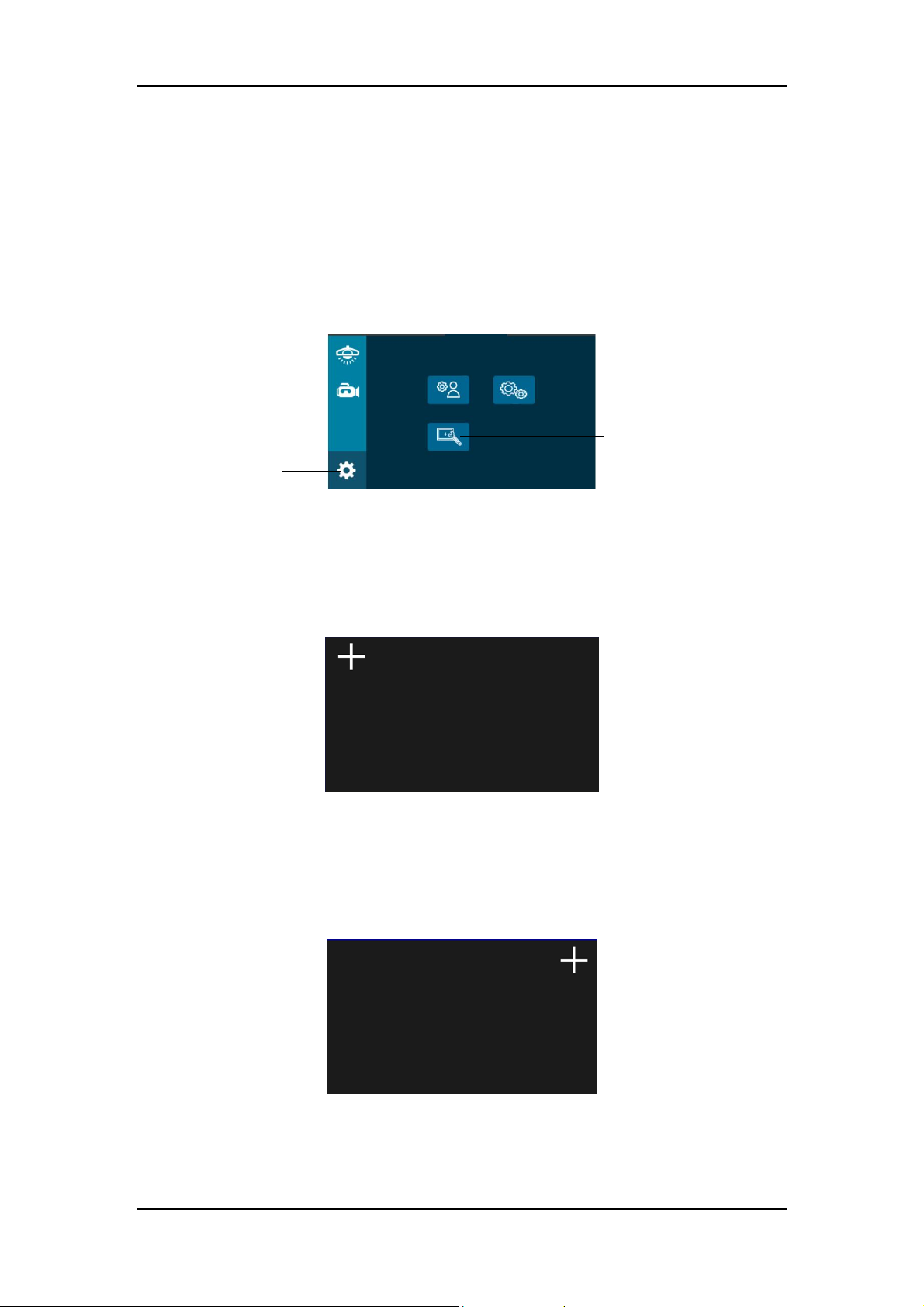
1. At the “Common functions” screen for the setting control, press the “Calibration” button
and input the default password “888888” to enter the calibration screen.
Calibration
Setting control
Figure 3-2 Calibration
2. Touch the center of the crosshair that appears on the top left corner of the screen.
Figure 3-3 Crosshair appearing on the top left corner
3. Touch the center of the crosshair that appears on the top right corner of the screen.
Figure 3-4 Crosshair appearing on the top right corner
3-7
Page 52
Maintenance
4. Touch the center of the crosshair that appears on the bottom right corner of the screen.
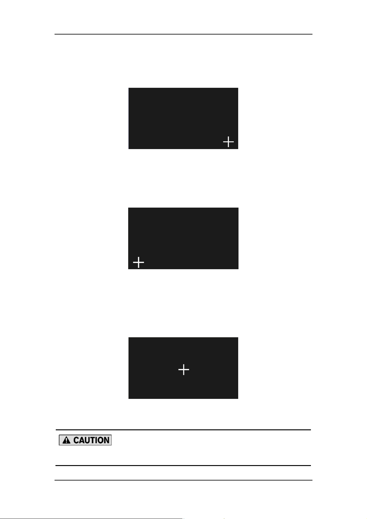
Figure 3-5 Crosshair appearing on the bottom right corner
5. Touch the center of the crosshair that appears on the bottom left corner of the screen.
Figure 3-6 Crosshair appearing on the bottom left corner
6. Touch the center of the crosshair that appears in the central area of the screen to
complete the calibration.
Figure 3-7 Crosshair appearing in the central area
The touch screen not calibrated well may not function properly.
3-8
Page 53
Maintenance
3.5 Replacing Battery of Infrared Remote Control
(optional)
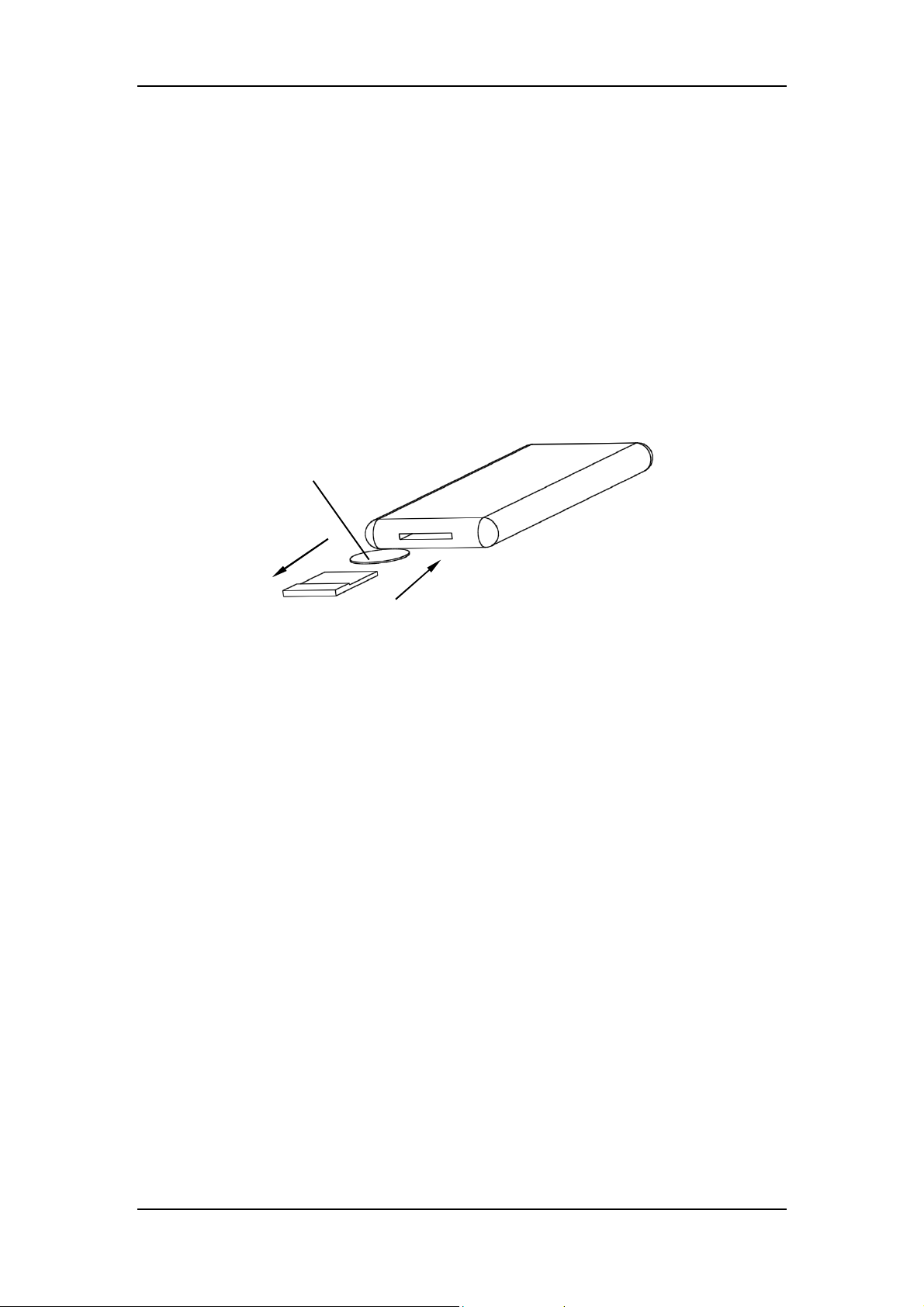
You can replace the battery as instructed below:
1. Press the slot towards right.
2. Pull out the battery box.
3. Replace the battery, and then push the box back.
Battery
Figure 3-8 Replacing the battery
3-9
Page 54
Maintenance
A B
3.6 Adjusting System
Before maintaining or servicing the surgical light, be sure to shut off the
mains supply first.
3.6.1 Adjusting Braking Force
3.6.1.1Spring Arm (Standard and LCH)
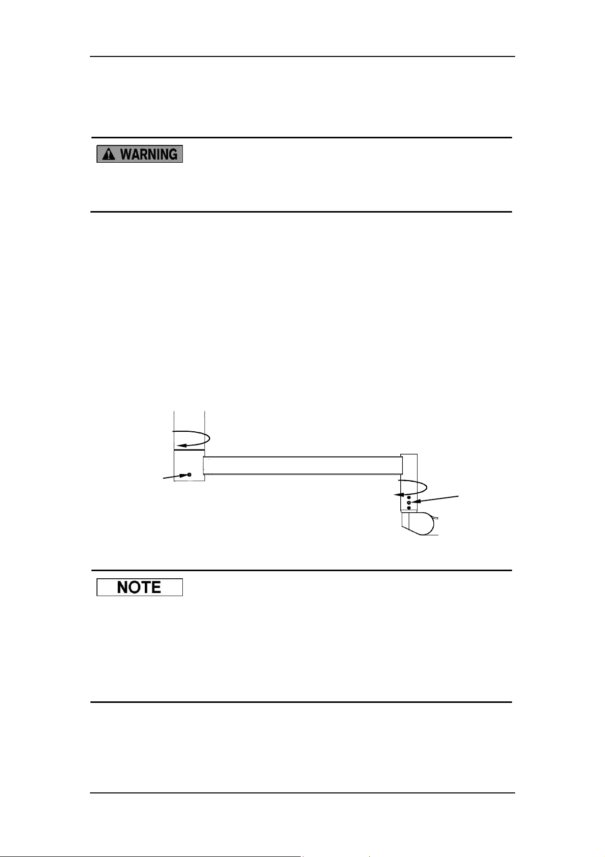
1. If the surgical light cannot stay at the desired position, you can adjust the braking screws
at joint A and/or B as needed.
2. If the swivel arm moves too easily, adjust the two braking screws at joint A with a 5mm
Allen key.
3. If the spring arm moves too easily, adjust the two braking screws at joint B with a 5mm
Allen key.
>360°/about 320°
>360°/about 320°
Figure 3-9 Positions of braking screws
It is recommended that the braking screw at point A be tighter than point B.
The swivel range of the swivel arm and spring arm can be restricted by
internal limit stops.
If the surgical light is configured with the HD camera system or display, the
swivel range of the swivel arm and spring arm is about 320°.
3-10
Page 55
Maintenance
B
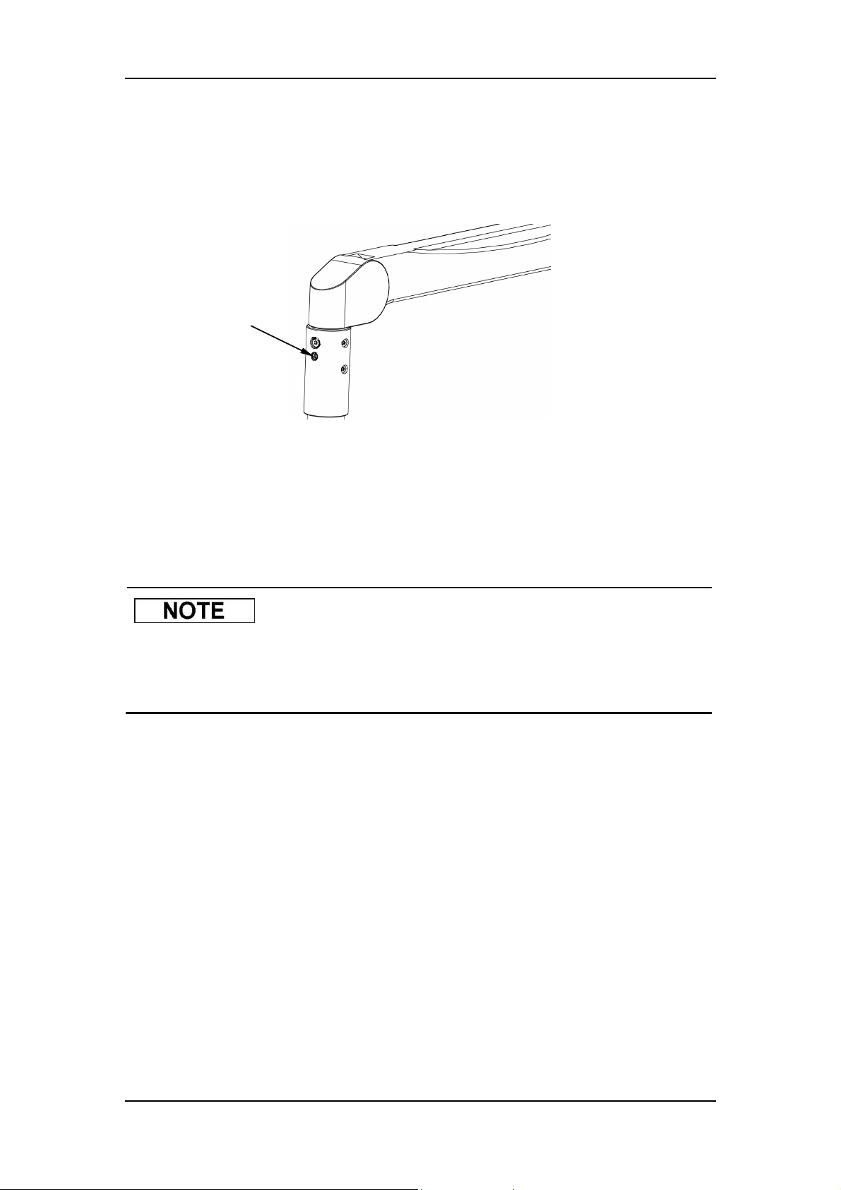
3.6.1.2HyLED 760M/730M Spring Arm
If the spring arm moves too easily, adjust the braking screw at joint B with a 5mm Allen key.
Figure 3-10 Position of braking screw
3.6.2 Adjusting Spring Arm
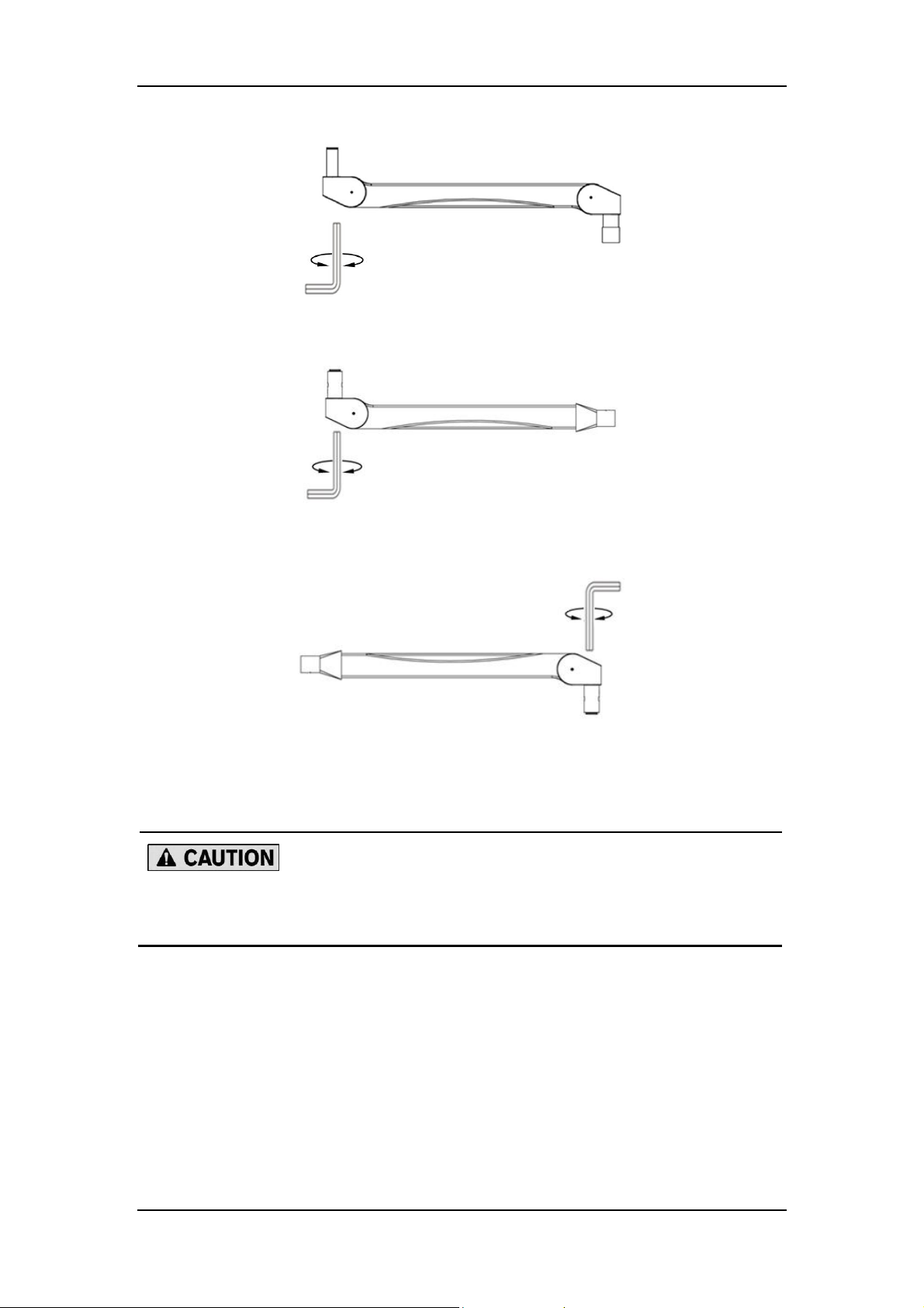
3.6.2.1Adjusting Counterweight
When adjusting the spring arm, raise it to a position approx. 10° above the
horizontal to release the adjustment screw. If necessary, set the upper stop
to a higher position. See section “Adjusting Height Stop” for details.
If the surgical light cannot be positioned at the desired height, you can adjust the load capacity
of the spring arm.
1. Insert a 5mm Allen key into the adjusting hole as far as possible.
2. Adjust the hexagon socket screw:
If the light tends to move upward, turn the Allen key in the “-” direction.
If the light tends to move downward, turn the Allen key in the “+” direction.
3-11
Page 56
Maintenance
+ +
+
-
Figure 3-11 Adjusting the standard spring arm
-
Figure 3-12 Adjusting the LCH spring arm
-
Figure 3-13 Adjusting the spring arm of HyLED 760M/730M
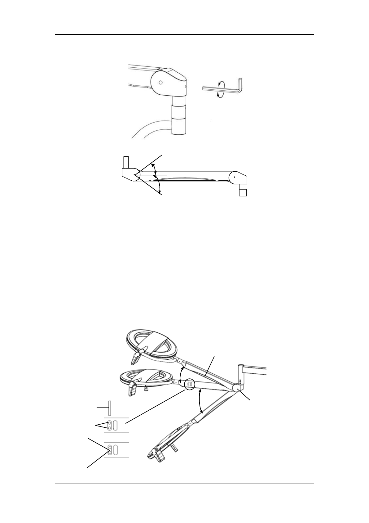
3.6.2.2Adjusting Height Stop
When adjusting the height stop, pay attention to the distance between the
floor and the ceiling. Make sure the lighthead does not collide with anything.
3.6.2.2.1Standard Spring Arm
Vertical movement of the light is limited by a fixed lower stop and an adjustable upper stop.
The adjustable upper stop can be adjusted with a 5mm Allen key.
Turn the Allen key in the “-” direction to reduce the stop.
Turn the Allen key in the “+” direction to raise the stop.
3-12
Page 57
Maintenance
+
+
-
About 45°
About 50°
Figure 3-14 Adjusting the height stop of standard spring arm
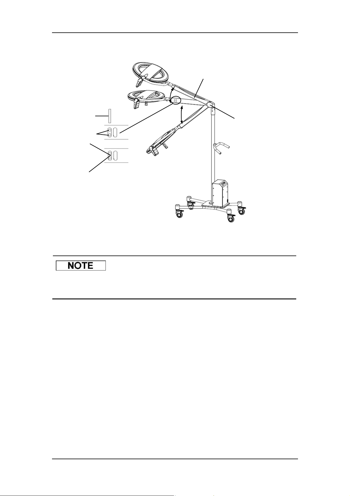
3.6.2.2.2LCH Spring Arm and Spring Arm of HyLED 760M/730M
1. Level the LCH spring arm.
2. Remove the two screws fixing the cover and then remove the cover.
3. Use a pin to adjust the height stop.
Turn the pin in the “-” direction to reduce the stop.
Turn the pin in the “+” direction to raise the stop.
4. Install the cover and secure it by the two fixing screws.
Cover
About 20°
Pin
Adjusting hole
-
Figure 3-15 Adjusting the height stop of the LCH spring arm
About 40°
3-13
Screw fixing the cover
Page 58
Maintenance
+
About 20°
Cover
Pin
About 40°
Adjusting hole
-
Figure 3-16 Adjusting the height stop of the spring arm of HyLED 760M/730M
Screw fixing the cover
The pin is delivered together with the LCH spring arm and the spring arm of
HyLED 760M/730M.
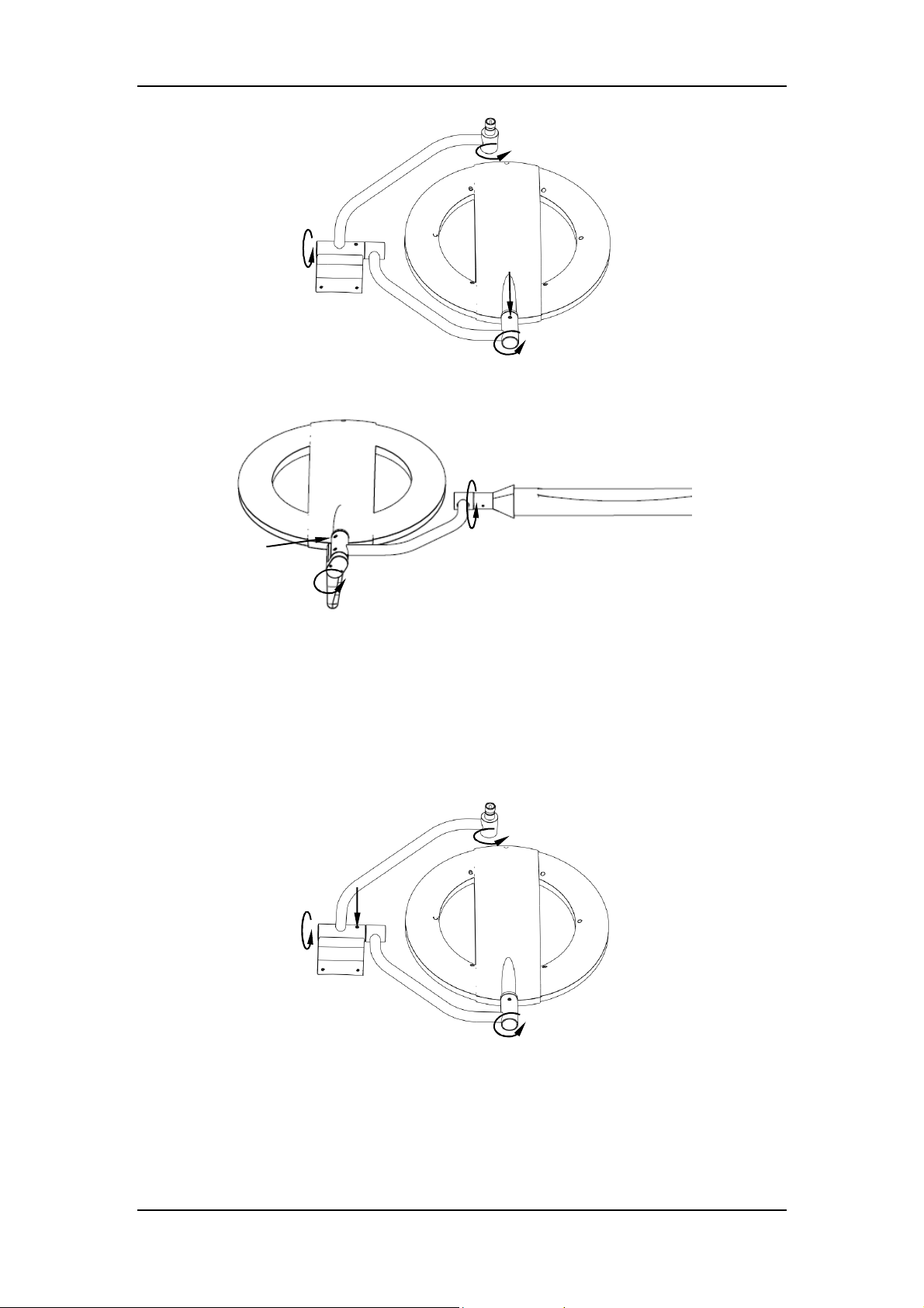
3.6.3 Adjusting Gimbal Joint
If the gimbal joint cannot keep the lighthead staying at the desired position, you can adjust the
braking force of joints A and B.
1. Adjusting Joint A
Use a 5mm Allen key to adjust the braking screw until the desired braking force is
obtained.
3-14
Page 59
About 300°
A
Maintenance
>360° /about 320°
A
About 300°
Figure 3-17 Adjusting joint A
>360°/about 300°
About 300°
Figure 3-18 Adjusting joint A
2. Adjusting Joint B
Use a 5mm Allen key to adjust the braking screw until the desired braking force is
obtained.
About 300°
>360° /about 320°
B
About 300°
Figure 3-19 Adjusting joint B
3-15
Page 60
Maintenance
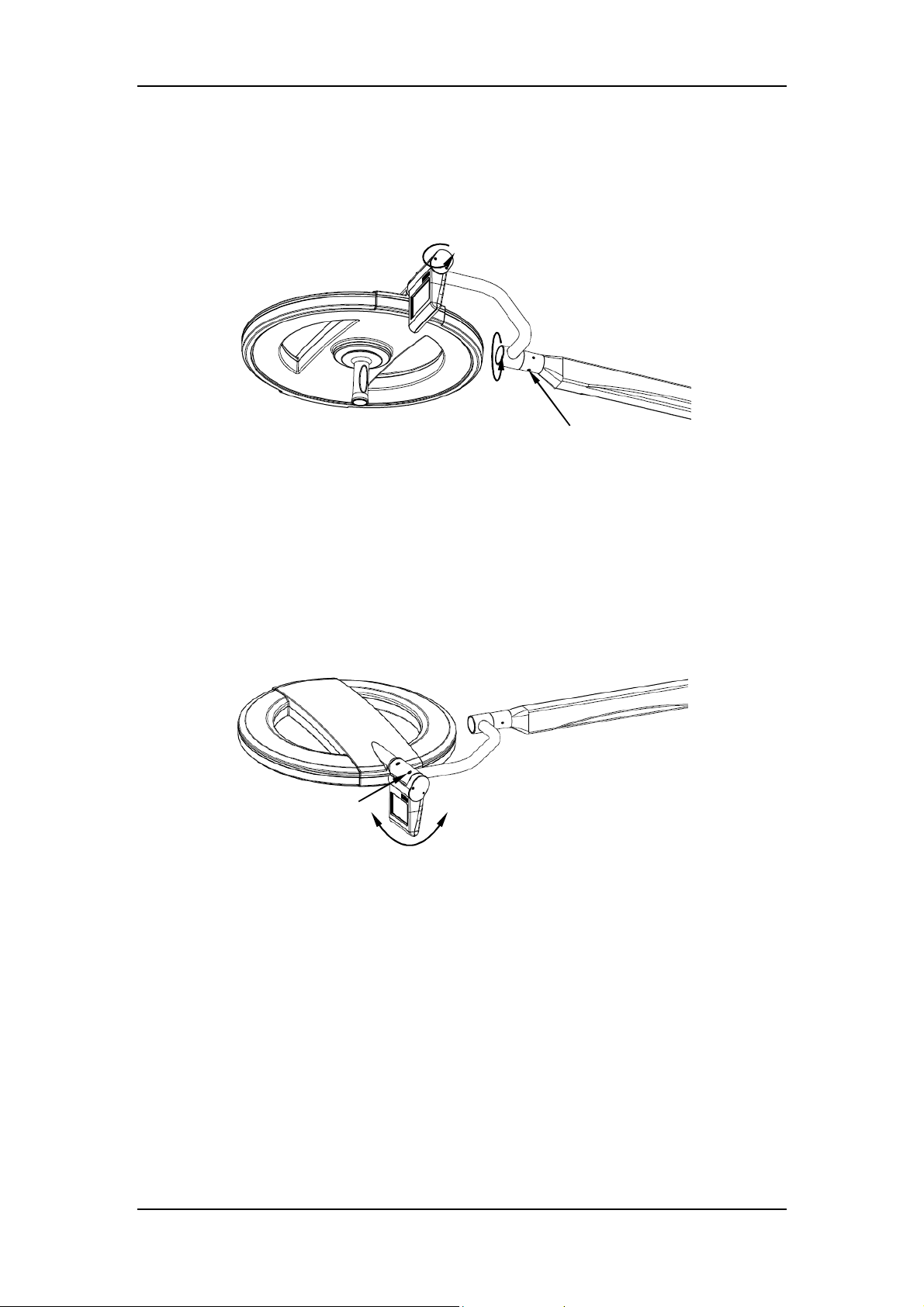
Use a 5mm flat-bladed screwdriver to turn the braking screw until the desired braking
force is obtained.
About 300°
>360°/about 300°
B
Figure 3-20 Adjusting joint B
3.6.4 Adjusting Braking Force of Rotatable Control
Panel/Touch Control Panel (optional)
If the rotatable control panel/touch control panel cannot stay at the desired position, adjust the
braking screw with a 5mm Allen key.
Braking screw
Figure 3-21 Position of braking screw
About 90°
3-16
Page 61

4 Troubleshooting
This chapter is meant to help you solve common problems only. In case you
encounter problems not included in this chapter or following the introduced
methods cannot solve the problem, contact the customer service
department authorized by Nanjing Mindray for help. Unauthorized device
servicing is not allowed.
Device servicing is to be performed by personnel authorized by Nanjing
Mindray only. Unauthorized device servicing may result in personal injury
and/or damage to the device or other property.
Device servicing should be strictly based on technical data supplied by
Nanjing Mindray. If you are in need of more technical data, contact the
customer service department authorized by Nanjing Mindray.
Error Cause Solution
Contact the customer service
The fuse is broken.
The light cannot be turned
on.
The light is flickering. Improper installation.
A group of LEDs or one
LED does not light up.
The illuminance cannot be
adjusted.
The surgical light cannot
switch to the MIS lighting
mode.
The illuminance is too low. The illuminance setting is too Increase the illuminance.
The power supply is cut off. Check the power supply.
Some electronic parts are
broken.
The LED is defective.
The LED wires are defective
or disconnected.
Some electronic parts are
broken.
Some electronic parts are
broken.
Some electronic parts are
broken.
department authorized by
Nanjing Mindray.
Contact the customer service
department authorized by
Nanjing Mindray.
Contact the customer service
department authorized by
Nanjing Mindray.
Contact the customer service
department authorized by
Nanjing Mindray.
Contact the customer service
department authorized by
Nanjing Mindray.
Contact the customer service
department authorized by
Nanjing Mindray.
4-1
Page 62

The lighthead collides with
other objects.
The spring arm moves too
easily.
The battery cannot be
charged.
The battery does not work,
or does not run as long as
the claimed time.
The glass surface has
scratch or cracking.
Service hours of the
sterilizable handle are
shorter.
The sterilizable handle is
worn or cracked.
The sterilizable handle does
not engage into the central
handle correctly.
The status indicator is red
and flashing, and the
illuminance indicator is
flashing.
The status indicator is
orange and flashing.
The status indicator is red
and flashing.
Error indicator
appears.
Error indicator
Troubleshooting
low. See 2.2.4 for details.
The height stop of the spring
arm is incorrect.
Braking screws are loose.
The battery is not connected
to mains power.
Adjust the height stop. See
3.6.2.2 for details.
Adjust the braking screws.
See 3.6.1 for details.
Connect the mains power.
Contact the customer service
The fuse is broken.
department authorized by
Nanjing Mindray.
The battery is not fully
charged, or the battery is
broken.
Contact the customer service
department authorized by
Nanjing Mindray.
Incorrect
cleaning/disinfection agents
are used or the glass is
cleaned before it has
See 3.2.1.4 and 3.2.1.5 for
detailed cleaning/disinfection
methods.
completely cooled down.
Incorrect sterilization method
is adopted.
Its service hours have
expired.
Sterilization parameters
(temperature, time)
exceeded.
Its service hours have
expired.
Communication error inside
the lighthead.
Communication error of the
surgical light system (Not
applicable to HyLED
760M/730M).
Voltage of the lighthead is
below normal working
voltage.
Communication error inside
the lighthead.
Check the sterilization. See
3.2.3 for details.
Replace the sterilizable
handle. See 2.2.2 for details.
Make sure the handle clicks
into place and check
the entire handle. See 2.2.2
for details.
Replace the sterilizable
handle.
Contact the customer service
department authorized by
Nanjing Mindray.
Contact the customer service
department authorized by
Nanjing Mindray.
Contact the customer service
department authorized by
Nanjing Mindray.
Contact the customer service
department authorized by
Nanjing Mindray.
Communication error of the Contact the customer service
4-2
Page 63

Troubleshooting
appears. surgical light system. department authorized by
Nanjing Mindray.
The infrared remote control
cannot work.
The display cannot display
the image or the image is
green.
The display cannot select
the exact signal source.
The display cannot display
the image clearly.
Its battery is dead.
The display jacks are not
connected correctly.
Improper setting.
Video connectors or cables
are broken.
The display automatically
scans the signal source at
every start.
The focus of the camera
does not match the image.
Replace the battery. See 3.5
for details.
Reconnect the jacks. See
2.5.1 for details.
Check the setting of the
display. See 2.5.1 for details.
Contact the customer service
department authorized by
Nanjing Mindray.
Refer to the instruction for
use of the display for how to
disable the auto scanning
function.
Switch to auto focus mode.
4-3
Page 64

This page is intentionally blank.
Page 65

5 Appendices
A Technical Specifications
A.1 Classification
A.1.1 According to Annex IX of the EU Directive 93/42/EEC
Class I.
A.1.2 According to Protection against Electrical Shock
Class I, internal electrical power source (optional).
No applied part.
The surgical light depends on the protective earth system to provide
protection against electrical shock. Where the integrity of the external
protective conductor in the installation or its arrangement is in doubt, the
surgical light shall be operated from its internal electrical power source.
A.1.3 According to the Mode of Operation
Continuous operation.
A.1.4 According to the Protection against Harmful Ingress of Water or
Particulate Matter
Surgical light: IPX0.
Lighthead only with control panel: IP54.
A.1.5 According to the Suitability for Use in an Oxygen Rich
Environment
Not suitable for use in the presence of an oxygen rich environment.
5-1
Page 66

Appendices
A.1.6 According to the Method of Sterilization
By methods validated and described by the manufacturer.
5-2
Page 67
A.2 Environment
A.2.1 Power Supply
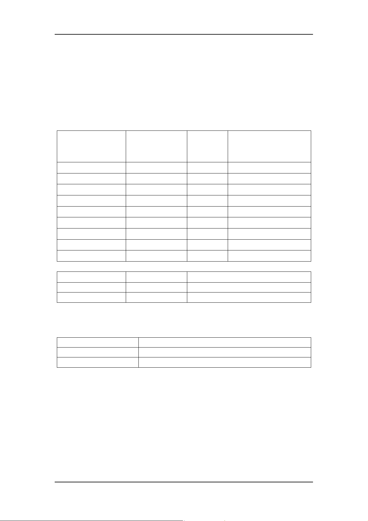
1. Power supply: 100-240V~ 50/60Hz
2. Input power
Appendices
Model Configuration
HyLED 730 Single lighthead 150 330
HyLED 760 Single lighthead 200 380
HyLED 730/730 Double lightheads 300 480
HyLED 730/760 Double lightheads 350 530
HyLED 760/760 Double lightheads 400 580
HyLED730/730/730 Triple lightheads 450 630
HyLED730/730/760 Triple lightheads 500 680
HyLED730/760/760 Triple lightheads 550 730
HyLED 760/760/760 Triple lightheads 600 780
Model Configuration Input power
HyLED 730M Mobile 100-240V~ 2.3-1.0A
HyLED 760M Mobile 100-240V~ 2.8-1.2A
Input
power VA
Input power
(with Camera and
Display) VA
3. Max. power consumption of all light sources:
Model Max. power consumption of all light sources
HyLED 730/HyLED 730M 65 W
HyLED 760/HyLED 760M 85 W
A.2.2 Fuse
1. 250V T 5AL (terminal block)
2. 250V T 6.3AH (power board)
A.2.3 Backup Battery Module (optional)
1. Power input: 100-240V~ 50/60Hz 1.4-0.6A
2. Power output: 24V DC, 6.5A.
3. Battery: 12V DC×2, 15Ah, lead-acid battery. For new and fully charged batteries, they
5-3
Page 68
Appendices
can last 100 minutes for the HyLED 760 lighthead at 70% of the maximum illuminance,
and 110 minutes for the HyLED 730. It takes about 8 hours to fully charge the batteries.
Replacement of backup batteries by inadequately trained personnel could
result in a hazard (such as excessive temperatures, fire or explosion). Make
sure the batteries are replaced by personnel authorized by Nanjing Mindray
only.
The surgical light is not compatible with the AC 24V power supply. Do not
connect them together. Otherwise, the light may be damaged.
It is recommended that the backup batteries be tested at least once every
month to extend their lives.
Note that the backup battery module provides temporary illumination before
the emergency power supply starts.
A.2.4 24V DC Power Supply (optional)
It is recommended that Mindray’s battery module be used as the 24V DC
power supply.
If the 24V DC power supply is provided from the customer site, it should meet the following
requirements.
1. The external 24V DC power supply should be isolated from the alternating current mains
supply. To meet the requirements of the isolation, the two methods below can be chosen
as a reference.
1) If the 24V DC power supply is from a power module, the power module should
comply with the IEC 60601-1 requirements.
2) If the 24V DC power supply is from a battery pack or UPS (uninterruptible power
supply), the battery pack or UPS should comply with the relevant IEC and ISO
standards.
2. Fluctuation range of the voltage at the input port of the Mindray’s backup power module:
5-4
Page 69
Appendices
22V-36V DC
3. DC power output: no less than 250W for single lighthead or 20% greater than that of
declared lighthead power listed in A.2.1
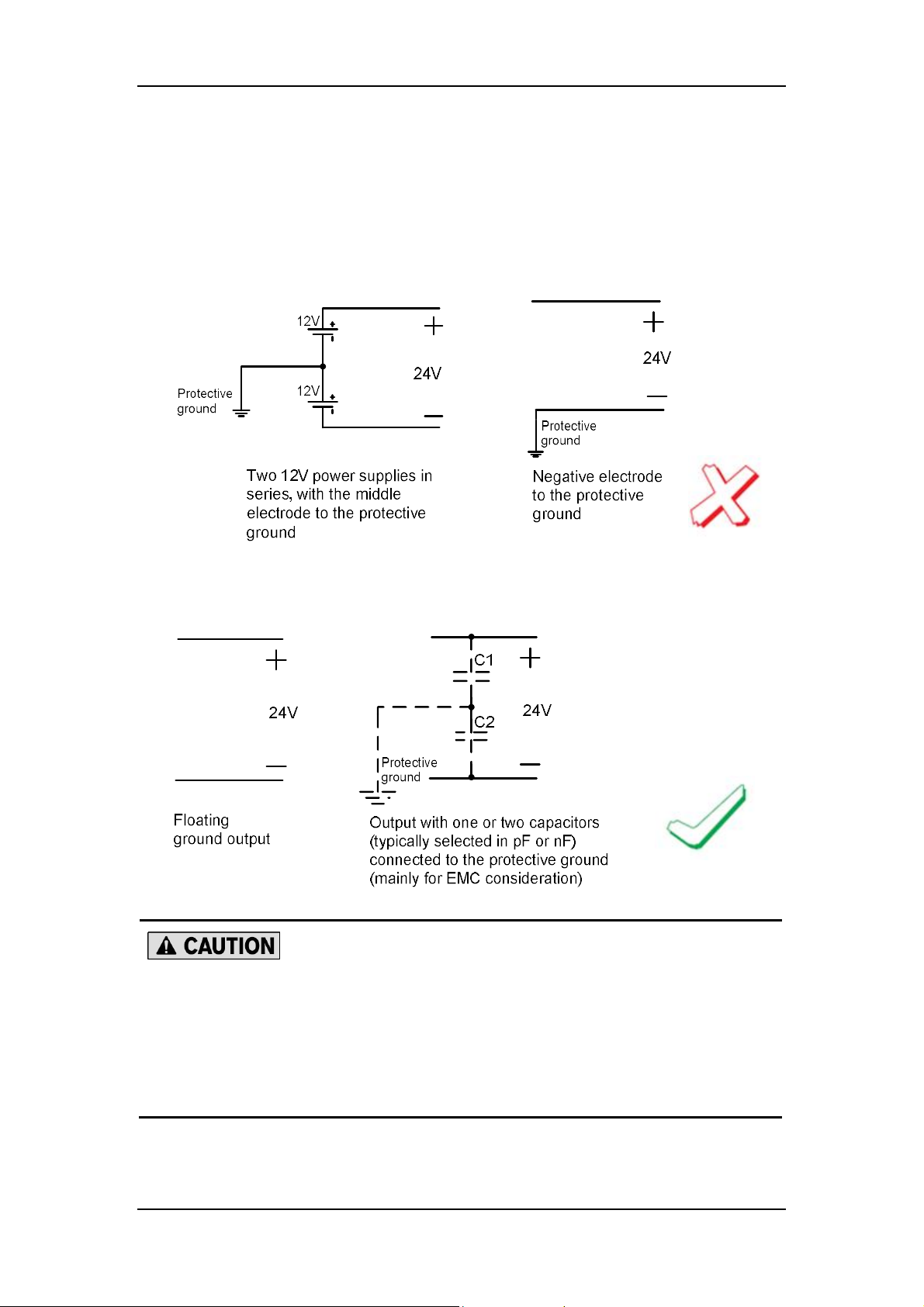
4. Ground connections:
1) Unacceptable ground connections:
2) Acceptable ground connections:
Each lighthead should be connected to a separate power supply, which
means each 24V DC power supply can only be connected to single backup
power module.
The DC power supply should be protected against the over-voltage,
over-current, short-circuit and surge.
5-5
Page 70
Appendices
A.2.5 Operating Environment
1. Temperature: 5°C to 40°C
2. Humidity: 30% to 75%,non-condensing
3. Atmospheric pressure: 70kPa to 106kPa
The above-mentioned operating environmental conditions do not apply to
the cameras and displays. See the accompanying documents of the camera
and display for their operating environmental conditions.
A.2.6 Storage and Transportation
1. Temperature: -40°C to 60°C
2. Humidity: 10% to 75%, non-condensing
3. Atmospheric pressure: 50kPa to106kPa
The above-mentioned storage and transportation conditions do not apply to
the camera and display. See the accompanying documents of the camera
and display for their storage and transportation environmental conditions.
During transportation, make sure that the surgical light is well protected
from rain, snow or mechanical collision.
The surgical light should be installed in a room that is dry, draughty, and
without caustic gas.
Do not store the surgical light outside.
Do not subject the surgical light to severe vibrations.
A.2.7 Environmental Protection
1. Packaging: The packaging is made of materials compatible with the environment. The
packaging should be disposed of in compliance with local governmental or hospital
regulations.
2. Batteries: Batteries can be turned in to your local disposal system for proper handling.
5-6
Page 71
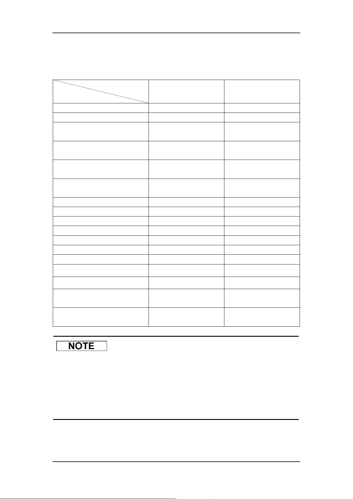
A.3 Optical Performance
Model
Appendices
Item
Maximum Illuminance (Ec) (1m) About 160000 lx About 130000 lx
Color Temperature About 4350k About 4350k
General Color Rendering Index
(Ra)
Specific Color Rendering Index
(R9)
Irradiance (Ee)
(Maximum illuminance)
Irradiance (Ee)
(Normal lighting)
Ee/Ec (average) 3.6 mW/(m2·lx) 3.6 mW/(m2·lx)
Min. Light Field Diameter (d10) About 180mm About 180mm
Max. Light Field Diameter (d10) About 300mm About 270mm
Light Distribution Diameter (d50) ≥ d10×50% ≥ d10×50%
Depth of Illumination (20%) About 1200mm About 1200mm
Depth of Illumination (60%) About 600mm About 600mm
Shadow Dilution: cavity About 100% About 100%
HyLED 760/HyLED 760M HyLED 730/HyLED 730M
About 96 About 96
About 97 About 97
About 540 W/m2 About 460 W/m2
≤ 480 W/m2 ≤ 450 W/m2
Shadow Dilution: single mask About 75% About 70%
Shadow Dilution: double mask About 55% About 55%
Shadow Dilution: single mask and
cavity
Shadow Dilution: double mask
and cavity
About 70% About 65%
About 50% About 50%
The optical performance is subject to fluctuations. Due to manufacturing
reasons, the real values may slightly differ from the data mentioned above.
Note that the original IEC 60601-2-41 defined Depth of Illumination as the
working range around 1,000mm below the emitting surface of the surgical
light, in which the illuminance reaches at least 20% of the central
illuminance. However, the latest version has changed the standard to 60%.
5-7
Page 72

Appendices
A.4 Camera Specifications
Item
Picture elements 440K pixels 2000K pixels
Lens f=3.5-98mm, F1.35-3.7 f=3.8-38mm, F1.8-3.4
Digital zoom 12× (324× with optical zoom) 12×(120× with optical zoom)
Recommended
illumination
S/N ratio 50 dB >50 dB
Electronic shutter
speed
Video signals output Composite Component
Power Supply 6-12V DC 6-12V DC
Operating
temperature/humidity
Storage
temperature/humidity
Rotatable Integrated
Camera (SD)
100-100000 lx 100-100000 lx
1/4-1/1000 s 1/1-1/10000 s
0 to 45°C/20 to 80% -5 to 60°C/20 to 80%
-20 to 60°C/20 to 95% -20 to 60°C/20 to 95%
Carrier-arm/Rotatable Integrated
Camera (HD)
5-8
Page 73

Appendices
A.5 EMC
The HyLED 760/HyLED 730/HyLED 760M/HyLED 730M series surgical lights meet the
requirements of EN/IEC 60601-1-2. Accessories listed in this manual comply with the
requirements of EN/IEC 60601-1-2 when in use with the surgical light.
Magnetic and electrical fields are capable of interfering with the proper performance of the
surgical light. For this reason make sure that all external devices operated in the vicinity of
the surgical light comply with the relevant EMC requirements. Mobile phone, X-ray equipment
or MRI devices are a possible source of interference as they may emit higher levels of
electromagnetic radiation.
The HyLED 760/HyLED 730/HyLED 760M/HyLED 730M series surgical lights can provide
steady illuminance and irradiance as the essential performance.
Using accessories and cables other than those specified may result in
increased electromagnetic emission or decreased electromagnetic
immunity of the device.
The device should not be used adjacent to or stacked with other devices. If
adjacent or stacked use is necessary, make sure that normal operation is
possible.
The device needs special precautions regarding EMC and needs to be
installed and put into service according to the EMC information provided
below.
Other devices may affect this device even though they meet the
requirements of CISPR.
Use of portable or mobile communication devices will degrade the
performance of the device.
5-9
Page 74
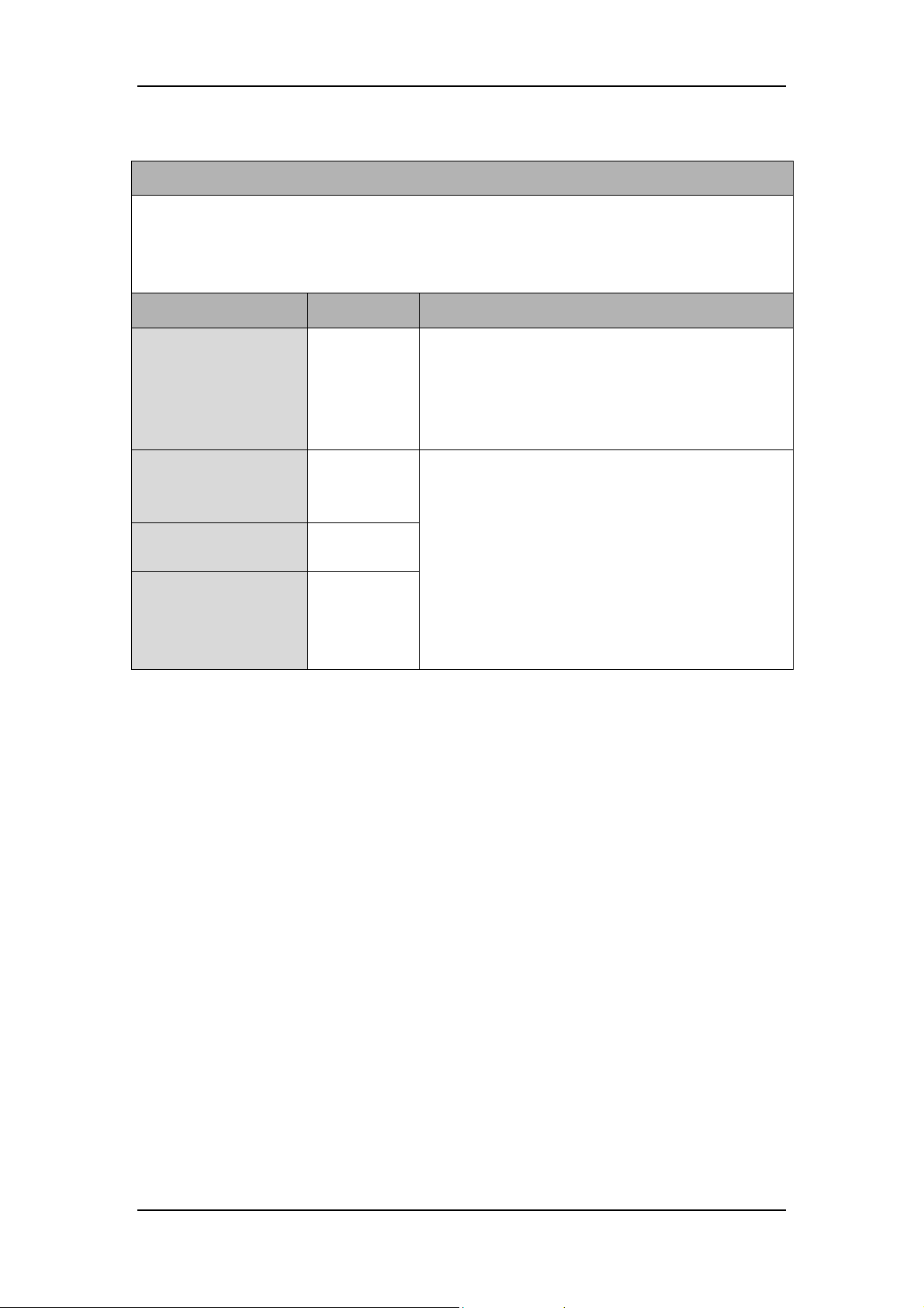
Appendices
Table 5-1 Guidance and Declaration-Electromagnetic Emissions
Guidance and Declaration-Electromagnetic Emissions
The HyLED 760/HyLED 730/HyLED 760M/HyLED 730M series surgical lights are suitable for
use in the specified electromagnetic environment. The customer or the user of the HyLED
760/HyLED 730/HyLED 760M/HyLED 730M series surgical lights should assure that they are
used in such an environment as described below.
Emissions test Compliance Electromagnetic environment - guidance
The HyLED 760/HyLED 730/HyLED 760M/HyLED
Radio frequency (RF)
emissions
CISPR 11
Radio frequency (RF)
emissions
CISPR 11
Harmonic emissions
IEC 61000-3-2
Voltage
fluctuations/flicker
emissions
IEC 61000-3-3
Group 1
Class A
Not
applicable
Not
applicable
730M series surgical lights use RF energy only for
their internal functions. Therefore, their RF
emissions are very low and are not likely to cause
any interference in nearby electronic device.
The HyLED 760/HyLED 730/HyLED 760M/HyLED
730M series surgical lights are suitable for use in all
establishments other than domestic and those
directly connected to a low voltage power supply
network which supplies buildings used for domestic
purposes.
5-10
Page 75

Appendices
Table 5-2 Guidance and Declaration-Electromagnetic Immunity
Guidance and Declaration-Electromagnetic Immunity
The HyLED 760/HyLED 730/HyLED 760M/HyLED 730M series surgical lights are suitable for
use in the specified electromagnetic environment. The customer or the user of the HyLED
760/HyLED 730/HyLED 760M/HyLED 730M series surgical lights should assure that they are
used in such an environment as described below.
Immunity test
EN/IEC 60601 test
level
Compliance level
Electromagnetic
environment - guidance
Floors should be wood,
Electrostatic
discharge
(ESD) IEC
61000-4-2
±6 kV contact
±8 kV air
±6 kV contact
±8 kV air
concrete or ceramic tile. If
floors are covered with
synthetic material, the
relative humidity should be
at least 30%.
Electrical fast
transient/burst
(EFT) IEC
61000-4-4
Surge
IEC 61000-4-5
±2 kV for power
supply lines
±1 kV for input/output
lines
(>3 m)
±1 kV differential
mode
±2 kV common mode
±2 kV for power
supply lines
±1 kV for input/output
lines
(>3 m)
±1 kV differential
mode
±2 kV common mode
Mains power quality
should be that of a typical
commercial or hospital
environment.
Mains power quality
should be that of a typical
commercial or hospital
environment. If the user of
the HyLED 760/HyLED
730/HyLED 760M/HyLED
730M series surgical lights
requires continued
operation during power
mains interruptions, it is
recommended that the
they be powered from an
uninterruptible power
Voltage dips,
short
interruptions
and voltage
variations on
power supply
input lines IEC
61000-4-11
<5 % UT (>95 % dip
in UT) for 0.5 cycle
40 % UT (60 % dip in
UT) for 5 cycles
70 % UT (30 % dip in
UT) for 25 cycles
<5 % UT (>95 % dip
in UT) for 5 s
<5 % UT (>95 % dip
in UT) for 0.5 cycle
40 % UT (60 % dip in
UT) for 5 cycles
70 % UT (30 % dip in
UT) for 25 cycles
<5 % UT (>95 % dip
in UT) for 5 s
supply (UPS).
Power
frequency
(50/60 HZ)
magnetic field
IEC 61000-4-8
3 A/m 3 A/m
Power frequency magnetic
fields should be at levels
characteristic of a typical
location in a typical
commercial or hospital
environment.
Note: UT is the AC mains voltage prior to application of the test level.
5-11
Page 76
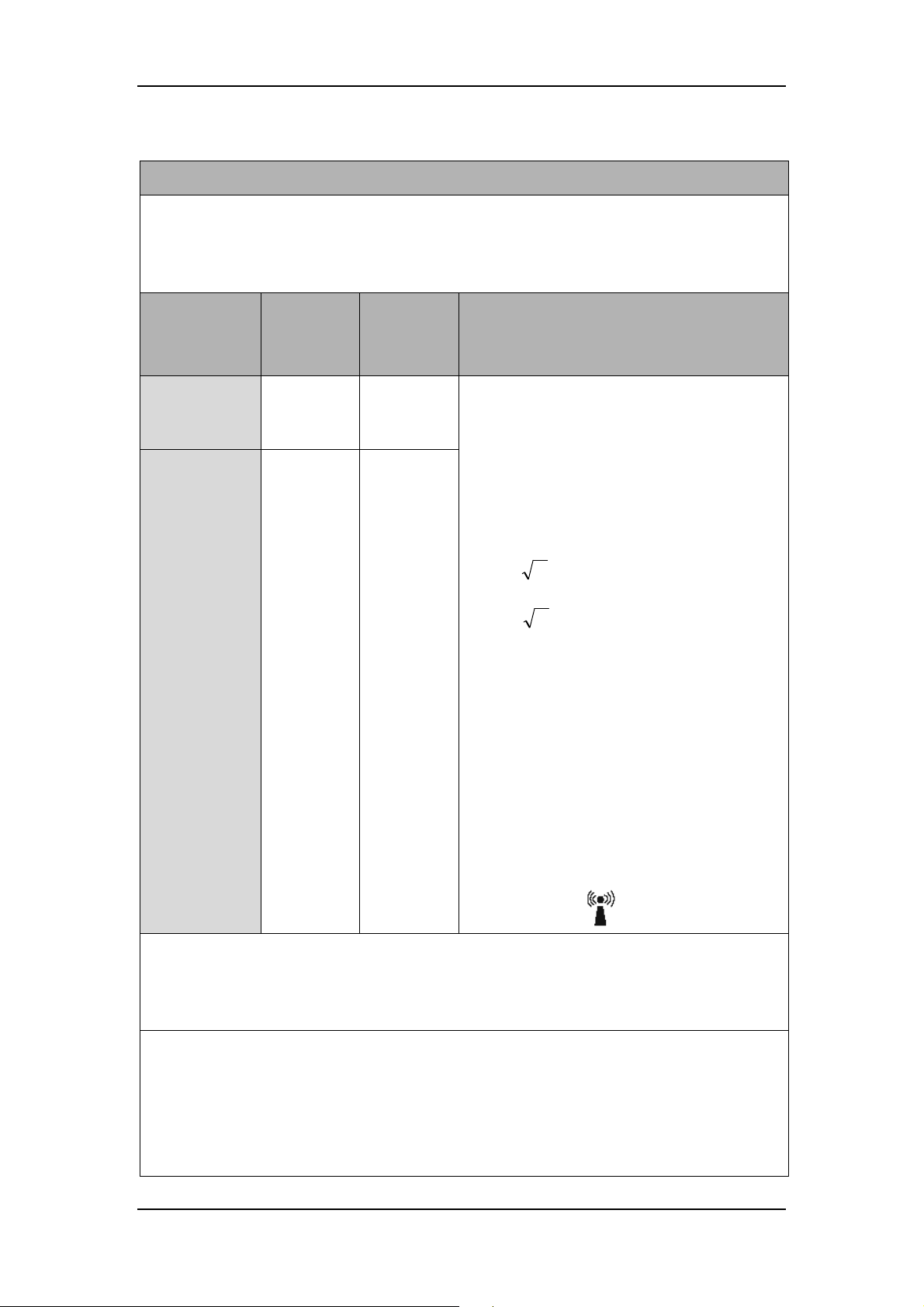
Appendices
Table 5-3 Guidance and Declaration-Electromagnetic Immunity
Guidance and Declaration-Electromagnetic Immunity
The HyLED 760/HyLED 730/HyLED 760M/HyLED 730M series surgical lights are suitable
for use in the specified electromagnetic environment. The customer or the user of the HyLED
760/HyLED 730/HyLED 760M/HyLED 730M series surgical lights should assure that they
are used in such an environment as described below.
Immunity test
Conduced RF
IEC61000-4-6
Radiated RF
IEC61000-4-3
EN/IEC
60601 test
level
3 Vrms
150 kHz to
80 MHz
3 V/m
80 MHz to
2.5 GHz
Complianc
e level
3 Vrms
150 kHz to
80 MHz
3 V/m
80 MHz to
2.5 GHz
Electromagnetic environment-guidance
Portable and mobile RF communications
device should be used no closer to any part of
the system, including cables, than the
recommended separation distance calculated
from the equation appropriate for the
frequency of the transmitter.
Recommended separation distances:
80 MHz-800 MHz
Pd 2.1
800 MHz-2.5 GHz
Pd 3.2
Where, P is the maximum output power
rating of the transmitter in watts (W)
according to the transmitter manufacturer and
is the recommended separation distance in
d
meters (m).
Field strengths from fixed RF transmitters, as
determined by an electromagnetic site survey
a
, should be less than the compliance level in
each frequency range b. Interference may
occur in the vicinity of device marked with the
following symbol: .
Note 1: At 80 MHz to 800 MHz, the separation distance for the higher frequency range
applies.
Note 2: These guidelines may not apply in all situations. Electromagnetic propagation is
affected by absorption and reflection from structures, objects and people.
a. Field strengths from fixed transmitters, such as base stations for radio (cellular/cordless)
telephones and land mobile radios, amateur radio, AM and FM radio broadcast and TV
broadcast cannot be predicted theoretically with accuracy. To assess the electromagnetic
environment due to fixed RF transmitters, an electromagnetic site survey should be
considered. If the measured field strength in the location in which the HyLED 760/HyLED
730/HyLED 760M/HyLED 730M series surgical lights are used exceeds the applicable RF
5-12
Page 77
Appendices
suitable for
eries
can help prevent electromagnetic interference by maintaining a minimum
HyLED
as recommended below,
not listed above, the recommended
separation distance D in meters (m) can be determined using the equation applicable to the
frequency of the transmitter, where P is the maximum output power rating of the transmitter in
compliance level above, the HyLED 760/HyLED 730/HyLED 760M/HyLED 730M series
surgical lights should be observed to verify normal operation. If abnormal performance is
observed, additional measures may be necessary, such as reorienting or relocating the
HyLED 760/HyLED 730/HyLED 760M/HyLED 730M series surgical lights.
b. Field strengths should be less than 3 V/m between 150 kHz and 80 MHz.
Table 5-4 Recommended Separation Distance between Portable/Mobile RF
Communications Device and the Device
Recommended Separation Distance between Portable/Mobile RF
Communications Device and the Device
The HyLED 760/HyLED 730/HyLED 760M/HyLED 730M series surgical lights are
use in an electromagnetic environment in which radiated RF disturbance is controlled. The
customer or the user of the HyLED 760/HyLED 730/HyLED 760M/HyLED 730M s
surgical lights
distance between portable/mobile RF communications device (transmitters) and the
760/HyLED 730/HyLED 760M/HyLED 730M series surgical lights
according to the maximum output power of the communications device.
Rated
maximum
output power
of transmitter
(W)
0.01 0.12 0.12 0.23
0.1 0.38 0.38 0.73
1 1.2 1.2 2.3
10 3.8 3.8 7.3
100 12 12 23
For transmitters rated at a maximum output power
watts (W) according to the transmitter manufacturer.
Note 1: At 80 MHz to 800 MHz, the separation distance for the higher frequency range
applies.
Note 2: These guidelines may not apply in all situations. Electromagnetic propagation is
affected by absorption and reflection from structures, objects and people.
Separation distance in meters (m) according to frequency of the
transmitter
150k-80MHz
Pd 2.1
80M-800MHz
Pd 2.1
800M-2.5GHz
Pd 3.2
5-13
Page 78

B Index
Appendices
A
Alternating current, 1-5
Atmospheric pressure limitation, 1-5
B
Backup Power Supply, 5-3, 5-4
Battery Indicator, 1-3
C
Castors, 1-3
Cleaning, 3-2, 3-4, 3-5
D
Date of manufacture, 1-5
Definitions, 1-5
Direct current, 1-5
F
Fuse, 5-3, 5-6
H
Humidity limitation, 1-5
M
Maintenance, 3-1
Manufacturer, 1-5
P
Pole, 1-3
Power module, 1-3
S
E
Environment, 5-3
Serial number, 1-5
T
Temperature limitation, 1-5
5-14
Page 79

This page is intentionally blank.
Page 80

P/N: 046-004572-00(6.0)
 Loading...