


User’s Manual
XP–AC–SL
Series
Pulse-Width Modulated,
Adjustable Speed Drives
for DC Brush Motors
Models:
XP01–115AC–E10U
XP01–115AC–SL
XP03–115AC–SL
250-0251r2.qxd:250-0251r2_readers.qxd 6/6/2007 2:53 PM Page i

Copyright © 2001 by
Minarik Corporation
All rights reserved. No part of this manual may be reproduced or transmitted in any form
without written permission from Minarik Corporation. The information and technical data
in this manual are subject to change without notice. Minarik Corporation and its
Divisions make no warranty of any kind with respect to this material, including, but not
limited to, the implied warranties of its merchantability and fitness for a given purpose.
Minarik Corporation and its Divisions assume no responsibility for any errors that may
appear in this manual and make no commitment to update or to keep current the
information in this manual.
Printed in the United States of America.
250-0251r2.qxd:250-0251r2_readers.qxd 6/6/2007 2:53 PM Page ii

Safety Warnings
Note: This symbol denotes an important safety message. Please read
these sections carefully before performing any instructions contained in this
manual.
• Have a qualified electrical maintenance technician install, adjust and service
this equipment. Follow the National Electrical Code and all other applicable
electrical and safety codes, including the provisions of the Occupational
Safety and Health Act (OSHA), when installing equipment.
• Reduce the chance of an electrical fire, shock, or explosion by proper
grounding, over current protection, thermal protection, and enclosure. Follow
sound maintenance procedures.
i
250-0251r2.qxd:250-0251r2_readers.qxd 6/6/2007 2:53 PM Page i

ii
Table of Contents
Specifications . . . . . . . . . . . . . . . . . . . . . . . . . . . . . . . . . . . . . . . . . . . . . . . . . . . . . .1
Dimensions . . . . . . . . . . . . . . . . . . . . . . . . . . . . . . . . . . . . . . . . . . . . . . . . . . . . . . . . .2
Installation . . . . . . . . . . . . . . . . . . . . . . . . . . . . . . . . . . . . . . . . . . . . . . . . . . . . . . . . .4
Mounting . . . . . . . . . . . . . . . . . . . . . . . . . . . . . . . . . . . . . . . . . . . . . . . . . . . . . . . . . . . . . .4
Wiring . . . . . . . . . . . . . . . . . . . . . . . . . . . . . . . . . . . . . . . . . . . . . . . . . . . . . . . . . . . . . . . . .5
Shielding guidelines . . . . . . . . . . . . . . . . . . . . . . . . . . . . . . . . . . . . . . . . . . . . . . . . .6
Line fusing . . . . . . . . . . . . . . . . . . . . . . . . . . . . . . . . . . . . . . . . . . . . . . . . . . . . . . . . . . . .7
Speed adjust potentiometer . . . . . . . . . . . . . . . . . . . . . . . . . . . . . . . . . . . . . . . . . . . . . . . .7
Connections . . . . . . . . . . . . . . . . . . . . . . . . . . . . . . . . . . . . . . . . . . . . . . . . . . . . . . . .9
XP-AC-SL series connections . . . . . . . . . . . . . . . . . . . . . . . . . . . . . . . . . . . . . . . . . . . . .9
Motor . . . . . . . . . . . . . . . . . . . . . . . . . . . . . . . . . . . . . . . . . . . . . . . . . . . . . . . . . . . .9
Power input . . . . . . . . . . . . . . . . . . . . . . . . . . . . . . . . . . . . . . . . . . . . . . . . . . . . . .10
Line fuse . . . . . . . . . . . . . . . . . . . . . . . . . . . . . . . . . . . . . . . . . . . . . . . . . . . . . . . .10
XP-AC-E10U series connections . . . . . . . . . . . . . . . . . . . . . . . . . . . . . . . . . . . . . . . . . .12
Motor . . . . . . . . . . . . . . . . . . . . . . . . . . . . . . . . . . . . . . . . . . . . . . . . . . . . . . . . . . .12
Power input . . . . . . . . . . . . . . . . . . . . . . . . . . . . . . . . . . . . . . . . . . . . . . . . . . . . . .12
Line fuse . . . . . . . . . . . . . . . . . . . . . . . . . . . . . . . . . . . . . . . . . . . . . . . . . . . . . . . .13
Voltage follower configuration . . . . . . . . . . . . . . . . . . . . . . . . . . . . . . . . . . . . . . . . . . . . .14
Operation . . . . . . . . . . . . . . . . . . . . . . . . . . . . . . . . . . . . . . . . . . . . . . . . . . . . . . . . .16
Before applying power . . . . . . . . . . . . . . . . . . . . . . . . . . . . . . . . . . . . . . . . . . . . . . . . . .16
Startup . . . . . . . . . . . . . . . . . . . . . . . . . . . . . . . . . . . . . . . . . . . . . . . . . . . . . . . . . . . . . . .16
Starting and Stopping Methods . . . . . . . . . . . . . . . . . . . . . . . . . . . . . . . . . . . . . . . . . . . .17
Automatic restart upon power restoration . . . . . . . . . . . . . . . . . . . . . . . . . . . . . . .18
250-0251r2.qxd:250-0251r2_readers.qxd 6/6/2007 2:54 PM Page ii

iiiTable of Contents
Line starting and line stopping . . . . . . . . . . . . . . . . . . . . . . . . . . . . . . . . . . . . . . .18
Decelerating to minimum speed . . . . . . . . . . . . . . . . . . . . . . . . . . . . . . . . . . . . . . . . . . .18
Dynamic braking . . . . . . . . . . . . . . . . . . . . . . . . . . . . . . . . . . . . . . . . . . . . . . . . . . . . . . .18
Calibration . . . . . . . . . . . . . . . . . . . . . . . . . . . . . . . . . . . . . . . . . . . . . . . . . . . . . . . . .21
MAXIMUM SPEED (MAX SPD) . . . . . . . . . . . . . . . . . . . . . . . . . . . . . . . . . . . . . . . . . . .24
MINIMUM SPEED (MIN) . . . . . . . . . . . . . . . . . . . . . . . . . . . . . . . . . . . . . . . . . . . . . . . .24
TORQUE (TQ) . . . . . . . . . . . . . . . . . . . . . . . . . . . . . . . . . . . . . . . . . . . . . . . . . . . . . . . . .25
IR COMP . . . . . . . . . . . . . . . . . . . . . . . . . . . . . . . . . . . . . . . . . . . . . . . . . . . . . . . . . . . .26
Application Notes . . . . . . . . . . . . . . . . . . . . . . . . . . . . . . . . . . . . . . . . . . . . . . . . . . .28
Multiple fixed speeds . . . . . . . . . . . . . . . . . . . . . . . . . . . . . . . . . . . . . . . . . . . . . . . . . . .28
Adjustable speeds using potentiometers in series . . . . . . . . . . . . . . . . . . . . . . . . . . . . .29
Independent adjustable speeds . . . . . . . . . . . . . . . . . . . . . . . . . . . . . . . . . . . . . . . . . . .30
RUN/JOG switch . . . . . . . . . . . . . . . . . . . . . . . . . . . . . . . . . . . . . . . . . . . . . . . . . . . . . . .31
Connection to other Minarik devices . . . . . . . . . . . . . . . . . . . . . . . . . . . . . . . . . . . . . . . .32
Leader-follower application . . . . . . . . . . . . . . . . . . . . . . . . . . . . . . . . . . . . . . . . . . . . . . .33
Single speed potentiometer control of multiple drives . . . . . . . . . . . . . . . . . . . . . . . . . .34
Reversing . . . . . . . . . . . . . . . . . . . . . . . . . . . . . . . . . . . . . . . . . . . . . . . . . . . . . . . . . . . .36
Reversing with a DIGI-LOK® controller . . . . . . . . . . . . . . . . . . . . . . . . . . . . . . . . . . . . .36
Troubleshooting . . . . . . . . . . . . . . . . . . . . . . . . . . . . . . . . . . . . . . . . . . . . . . . . . . . .39
Before troubleshooting . . . . . . . . . . . . . . . . . . . . . . . . . . . . . . . . . . . . . . . . . . . . . . . . . .39
Block Diagrams . . . . . . . . . . . . . . . . . . . . . . . . . . . . . . . . . . . . . . . . . . . . . . . . . . . . . . . .42
Replacement Parts . . . . . . . . . . . . . . . . . . . . . . . . . . . . . . . . . . . . . . . . . . . . . . . . . . . . .44
Unconditional Warranty . . . . . . . . . . . . . . . . . . . . . . . . . . . . . . . .inside back cover
250-0251r2.qxd:250-0251r2_readers.qxd 6/6/2007 2:54 PM Page iii

iv
Illustrations
Figure 1. XP-AC-SL Series Dimensions . . . . . . . . . . . . . . . . . . . . . . . . . . . . . . . . . . . . . . . . . . . . . .2
Figure 2. XP-AC-E10U Series Dimensions . . . . . . . . . . . . . . . . . . . . . . . . . . . . . . . . . . . . . . . . . . . .3
Figure 3. Speed Adjust Potentiometer . . . . . . . . . . . . . . . . . . . . . . . . . . . . . . . . . . . . . . . . . . . . . . . .8
Figure 4. XP-AC-SL Series Connections . . . . . . . . . . . . . . . . . . . . . . . . . . . . . . . . . . . . . . . . . . . . .11
Figure 5. XP-115AC-E10U Series Connections . . . . . . . . . . . . . . . . . . . . . . . . . . . . . . . . . . . . . . .13
Figure 6. XP-AC-SL Voltage Follower Connections . . . . . . . . . . . . . . . . . . . . . . . . . . . . . . . . . . . .14
Figure 7. XP-115AC-E10U Voltage Follower Connections . . . . . . . . . . . . . . . . . . . . . . . . . . . . . . .15
Figure 8. Decelerate to Minimum Speed . . . . . . . . . . . . . . . . . . . . . . . . . . . . . . . . . . . . . . . . . . . . .19
Figure 9. Dynamic Brake Connection . . . . . . . . . . . . . . . . . . . . . . . . . . . . . . . . . . . . . . . . . . . . . . .20
Figure 10. XP-AC-SL Calibration Trimpot Layout . . . . . . . . . . . . . . . . . . . . . . . . . . . . . . . . . . . . . .22
Figure 11. XP-AC-E10U Calibration Trimpot Layout . . . . . . . . . . . . . . . . . . . . . . . . . . . . . . . . . . . .23
Figure 12 Recommended Torque and IR COMP Settings . . . . . . . . . . . . . . . . . . . . . . . . . . . . . .27
Figure 13. Multiple Fixed Speeds . . . . . . . . . . . . . . . . . . . . . . . . . . . . . . . . . . . . . . . . . . . . . . . . . .28
Figure 14. Adjustable Fixed Speeds Using Potentiometers in Series . . . . . . . . . . . . . . . . . . . . . . .29
Figure 15. Independent Adjustable Speeds . . . . . . . . . . . . . . . . . . . . . . . . . . . . . . . . . . . . . . . . . . .30
Figure 16. RUN/JOG Switch Connection to Speed Adjust Potentiometer . . . . . . . . . . . . . . . . . . . .31
Figure 17. Connecting an XP–AC Series Drive to a PCM4 or DLC600 . . . . . . . . . . . . . . . . . . . . .32
Figure 18. Leader-Follower Application . . . . . . . . . . . . . . . . . . . . . . . . . . . . . . . . . . . . . . . . . . . . . .33
Figure 19. Single Speed Potentiometer Control of Multiple Drives . . . . . . . . . . . . . . . . . . . . . . . . .34
Figure 20. PCM4 Speed Ratio Application . . . . . . . . . . . . . . . . . . . . . . . . . . . . . . . . . . . . . . . . . . .35
Figure 21. Reversing Circuit Connections . . . . . . . . . . . . . . . . . . . . . . . . . . . . . . . . . . . . . . . . . . . .37
Figure 22. Reversing with a DLC600 . . . . . . . . . . . . . . . . . . . . . . . . . . . . . . . . . . . . . . . . . . . . . . . .38
Figure 23. XP–AC Series Block Diagram . . . . . . . . . . . . . . . . . . . . . . . . . . . . . . . . . . . . . . . . . . . .42
Figure 24. XP–AC Series Input Circuit Diagram . . . . . . . . . . . . . . . . . . . . . . . . . . . . . . . . . . . . . . .43
250-0251r2.qxd:250-0251r2_readers.qxd 6/6/2007 2:54 PM Page iv

1
Specifications
Max. Continuous
Armature HP Range
Current with 115 VAC
Model (DC Amps) Applied
XP01-115AC-E10U 1 1/100 – 1/25
XP01–115AC-SL 1 1/100 – 1/25
XP03–115AC-SL 3 1/20 – 1/4
AC Line Voltage 115 VAC ±10%, 50/60 Hz, single phase
Armature Voltage Range 0–130 VDC
Form Factor (at base speed) 1.05
Acceleration/Deceleration Time Range (no load) 1 second
Analog Input Voltage Range (signal must be isolated) 0 – 5 VDC
Input Impedance (S1 to S2) approximately 150K ohms
Speed Regulation 1% base speed or better
Ambient Temp. Range (chassis drive) 10°C–55°C
Weight 0.3 lb
250-0251r2.qxd:250-0251r2_readers.qxd 6/6/2007 2:54 PM Page 1
2
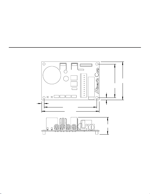
Dimensions
0.1875 [5]
TH501
I LIMIT
R502
MAX SPD
.035
R501
FU501
PWR ON
IL501
R503
P501
C501
BR501
C503
C502
D501
IR CO MP
P504
IL502
TQ
P503
MIN
P502
Q501
SO501
.052
4.125 [105]
4.5 [114]
3.00 [76]
2.625 [67]
0.1875 [5]
1.35 [34.29]
Figure 1. XP-AC-SL Series Dimensions
ALL DIMENSIONS IN INCHES [MILLIMETERS]
250-0251r2.qxd:250-0251r2_readers.qxd 6/6/2007 2:54 PM Page 2
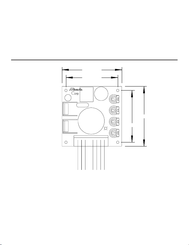
3Dimensions
ALL DIMENSIONS IN INCHES [MILLIMETERS]
MAX SPD MIN SPDIR COMP TORQUE
PWR ON
L1L2A1
A2
S3S2S1
TB501
Q501D501
C502
C503
C501
IL501
TH501
R501
BLACK
WHITE
BLUE
YELLOW
PURPLE
BROWN
GRAY
1.95 [50]
2.25 [57]
1.95 [50]
2.25 [57]
Figure 2. XP-AC-E10U Series Dimensions
250-0251r2.qxd:250-0251r2_readers.qxd 6/6/2007 2:54 PM Page 3

4
Do not install, rewire, or remove this control with input power
applied. Doing so may cause fire or serious injury. Make sure you
have read and understood the Safety Warnings on page i before
attempting installation.
The chassis must be earth grounded. Use a star washer beneath the
head of at least one of the mounting screws to penetrate the
anodized chassis surface and to reach bare metal.
Warning
Mounting
• Drive components are sensitive to electrostatic fields. Avoid contact with the circuit
board directly. Hold drive by the chassis only.
• Protect the drive from dirt, moisture, and accidental contact.
• Provide sufficient room for access to the terminal block and calibration trimpots.
• Mount the drive away from heat sources. Operate the drive within the specified
ambient operating temperature range.
• Prevent loose connections by avoiding excessive vibration of the drive.
• Mount drive with its board in either a horizontal or vertical plane. Six 0.19 in. (5
mm) wide slots in the chassis accept #8 pan head screws. Fasten either the large
base or the narrow flange of the chassis to the subplate.
Installation
250-0251r2.qxd:250-0251r2_readers.qxd 6/6/2007 2:54 PM Page 4

5Installation
Do not install, remove, or rewire this equipment with power
applied. Failure to heed this warning may result in fire, explosion,
or serious injury.
Circuit potentials are at 115 or 230 VAC above ground. To prevent
the risk of injury or fatality, avoid direct contact with the printed
circuit board or with circuit elements.
Do not disconnect any of the motor leads from the drive unless
power is removed and the drive is disabled. Opening any one
motor lead may destroy the drive.
Warning
Wiring
• Use 18-24 AWG wire for speed adjust potentiometer wiring. Use 14–16 AWG wire
for AC line (L1, L2) and motor (A1 and A2) wiring.
250-0251r2.qxd:250-0251r2_readers.qxd 6/6/2007 2:54 PM Page 5

6 Installation
Shielding guidelines
As a general rule, Minarik recommends shielding of all conductors.
If it is not practical to shield power conductors, Minarik recommends shielding all
logic-level leads. If shielding of logic leads is not practical, the user should twist all
logic leads with themselves to minimize induced noise.
It may be necessary to earth ground the shielded cable. If noise is produced by
devices other than the drive, ground the shield at the drive end. If noise is generated
by a device on the drive, ground the shield at the end away from the drive. Do not
ground both ends of the shield.
If the drive continues to pick up noise after grounding the shield, it may be necessary
to add AC line filtering devices, or to mount the drive in a less noisy environment.
Logic wires from other input devices, such as motion controllers and PLL velocity
controllers, must be separated from power lines in the same manner as the logic I/O
on this drive.
Warning
Under no circumstances should power and logic leads be bundled
together. Induced voltage can cause unpredictable behavior in any
electronic device, including motor controls.
250-0251r2.qxd:250-0251r2_readers.qxd 6/6/2007 2:54 PM Page 6

7Installation
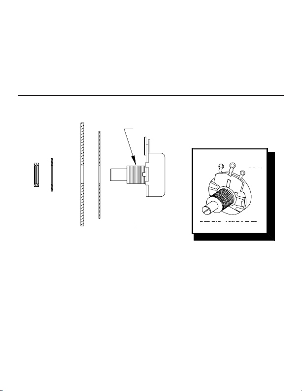
Mount the speed adjust potentiometer through a 0.38 in. (10 mm) hole with the
hardare provided (see Figure 3, page 8). Install the circular insulating disk between
the panel and the 10K ohm speed adjust potentiometer.
Twist the speed adjust potentiometer wire to avoid picking up unwanted electrical
noise. If speed adjust potentiometer wires are longer than 18 in. (457 mm), use
shielded cable. Keep the speed adjust potentiometer wires separate from power
leads (L1, L2, A1, A2).
Be sure that the potentiometer tabs do not make contact with the
potentiometer enclosure. Grounding the input will cause damage to
the drive.
Warning
Speed adjust potentiometer
Line fusing
Protect all Minarik drives with AC line fuses. For XP03-115AC-SL, use fast acting AC line
fuse rated for 8 amps at 250 volts. For all other XP series drives, use fast acting AC line
fuse rated for 3 amps at 250 volts. Fuse only the “hot” side of the AC line (L1).
250-0251r2.qxd:250-0251r2_readers.qxd 6/6/2007 2:54 PM Page 7
8 Installation
Figure 3. Speed Adjust Potentiometer
POT TAB A SSIGNMENTS
WIPER
CW
CCW
SPEED ADJUST
POTENTIOMETER
INSULATING DI SK
PANEL
STAR
WASHER
NUT
MOUNT THROUGH A 0.38 IN. (10 MM) HOLE
NUT
STAR
WASHER
PANEL
CW
CCW
WIPER
SPEED ADJUST
POTENTIOMETER
INSULATING DISK
POT TAB ASSIGNMENTS
MOUNT THROUGH A 0.38 IN. (10 MM) HOLE
250-0251r2.qxd:250-0251r2_readers.qxd 6/6/2007 2:54 PM Page 8

9
Do not connect this equipment with power applied. Failure to heed
this directive may result in fire or serious injury.
Minarik strongly recommends the installation of a master power
switch in the voltage input line, as shown in Figure 5 (page 13). The
switch contacts should be rated at a minimum of 200% of motor
nameplate current and 250 volts.
Warning
XP-AC-SL series connections
Connect the power input leads, an external line fuse and a DC motor as shown in
Figure 4 (page 11).
Motor
Minarik drives supply voltage from A1 and A2 terminals. It is assumed throughout this
manual that, when A1 is positive with respect to A2, the motor will rotate clockwise
(CW) while looking at the output shaft protruding from the front of the motor. If this is
opposite of the desired rotation, simply reverse the wiring of A1 and A2 with each
other.
Connections
250-0251r2.qxd:250-0251r2_readers.qxd 6/6/2007 2:54 PM Page 9

10 Connections
Connect a DC motor to terminals A1 and A2 as shown in Figure 4 (page 11). Ensure
that the motor voltage and current ratings are consistent with the drive’s output
voltage and current.
Power input
Connect the AC line power leads to terminals L1 and L2, or to a single-throw, doublepole master power switch (recommended).
Line fuse
Wire an external line fuse between the stop switch (if installed) and the L1 terminal as
shown in Figure 4. The XP03-115-SL line fuse should be rated at 250 volts and 8
amps.
250-0251r2.qxd:250-0251r2_readers.qxd 6/6/2007 2:54 PM Page 10

11Connections
HEADER
BLOCK
TERMINAL
PLUG
L1 DC+
IN
F1 A1 S1 S2 S3 A2 F2 DC-
IN
L2
L2DC -
IN
F2A2S3S2S1A1F1DC +
IN
L1
SO501
CW
SPD
ADJ
POT
10 KΩ
MOTOR
MOTOR
FIELD
LEADS
( SHUNT-
WOUND
MOTORS
ONL Y )
115 VAC
INPUT
STOP
SWITCH
FUSE
Figure 4. XP-AC-SL Series Connections
HEADER
BLOCK
TERMINAL
PLUG
FUSE
STOP
SWITCH
115 VAC
INPUT
10K OHM
SPEED
ADJUST
POT
CW
S0501
MOTOR
FIELD LEADS
(SHUNTWOUND
MOTORS
ONLY)
MOTOR
250-0251r2.qxd:250-0251r2_readers.qxd 6/6/2007 2:54 PM Page 11

12 Connections
XP-AC-E10U series connections
Connect the power input leads, an external line fuse and a DC motor to terminal
board TB501 as shown in Figure 5 (page 13).
Motor
Minarik drives supply motor voltage from A1 and A2 terminals. It is assumed
throughout this manual that, when A1 is positive with respect to A2 , the motor will
rotate clockwise (CW) while looking at the output shaft protruding from the front of the
motor. If this is opposite of the desired rotation, simply reverse the wiring of A1 and
A2 with each other.
Connect a DC motor to terminals A1 and A2 as shown in Figure 5 (page 13). Ensure
that the motor voltage and current ratings are consistent with the drive’s output
voltage and current.
Power input
Connect the AC line power leads to terminals L1 and L2, or to a single-throw, doublepole master power switch (recommended).
250-0251r2.qxd:250-0251r2_readers.qxd 6/6/2007 2:54 PM Page 12

13Connections
Line fuse
Wire an external line fuse between the stop switch (if installed) and the L1 terminal.
The line fuse should be rated at 250 volts and 3 amps.
MOTOR
C501
MAX SPDMIN SPD
IR COMP
PWR ON
TB501
D501
IL5 0 1
TH501
R501
Q50
STOP
SWITCH
FUSE
+
10K Ω
SPEED
ADJUST
POT
CW
115 VAC
INPUT
L1
L2
A1
A2
S3
S2
S1
Figure 5. XP-115AC-E10U Series Connections
115 VAC
INPUT
STOP
SWITCH
FUSE
MOTOR
CW
+
10K OHM
SPEED
ADJUST
POT
250-0251r2.qxd:250-0251r2_readers.qxd 6/6/2007 2:54 PM Page 13

14
Voltage follower configuration
Connections
Instead of using a speed adjust potentiometer, the drive may be wired to follow a 0–5
VDC voltage signal that is isolated from earth ground (Figure 6 & 7). Connect the
signal input (+) to S2. Connect the signal common (–) to S1. Make no connection to
S3. A potentiometer can be used to scale the analog input voltage.
To achieve greater linearity and control, use an interface device such as Minarik
model PCM4 to scale the analog input voltage. Follow the same wiring guidelines
used for speed adjust potentiometer wiring (see page 7 & 8).
Do not connect a non-isolated input voltage signal to any XP Series
drive. Connecting a non-isolated signal will damage the drive.
Warning
Figure 6. XP-AC-SL Voltage Follower Connections
A1 S1 S2 S3
SI G (+)
0 - 5 VDC
SI GNAL I NPUT
COM (- )
COM (-)
SIG (+)
0 - 5 VDC
SIGNAL INPUT
250-0251r2.qxd:250-0251r2_readers.qxd 6/6/2007 2:54 PM Page 14

15Connections
Figure 7. XP-115AC-E10U Voltage Follower Connections
C501
MAX SPDM
IR COMP
PWR ON
IL501
A1
S3
S2
S1
SIG (+)
COM (- )
ISOLATED
0 - 5 VDC
INPUT
ISOLATED
0 - 5 VDC INPUT
SIG (+)
COM (-)
250-0251r2.qxd:250-0251r2_readers.qxd 6/6/2007 2:54 PM Page 15

Startup
To start the drive:
1. Turn the speed adjust potentiometer full counterclockwise (CCW). If the drive is
following a voltage signal, set the voltage signal to 0 VDC.
2. Apply AC line voltage.
Before applying power
Verify that no conductive material is present on the printed circuit board.
16
Dangerous voltages exist on the drive when it is powered, and up to
30 seconds after power is removed and the motor stops. BE ALERT.
High voltages can cause serious or fatal injury. For your safety, use
personal protective equipment (PPE) when operating this drive.
Warning
Operation
250-0251r2.qxd:250-0251r2_readers.qxd 6/6/2007 2:54 PM Page 16

17Operation
Decelerating to minimum speed or coasting to a stop is
recommended for frequent stops. Do not use any of these methods
for emergency stopping. They may not stop a drive that is
malfunctioning. Removing AC line power (both L1 and L2) is the
only acceptable method for emergency stopping.
For this reason, Minarik strongly recommends installing an
emergency stop switch on both the L1 and L2 inputs (see
Connections, page 9).
Warning
3. Slowly advance the speed adjust potentiometer clockwise (CW). If the drive is
following a voltage signal, slowly increase the voltage signal. The motor slowly
accelerates as the potentiometer is turned CW, or the voltage signal is increased.
Continue until the desired speed is reached.
4. Remove AC line voltage from the drive to coast the motor to a stop.
If the motor or drive does not perform as described, disconnect the AC line voltage
immediately. Refer to the Troubleshooting section, page 38, for further assistance.
Starting and Stopping Methods
250-0251r2.qxd:250-0251r2_readers.qxd 6/6/2007 2:54 PM Page 17

18 Operation
Automatic restart upon power restoration
After a one-second time delay, all drives automatically run to set speed when power
is applied.
Line starting and line stopping
Line starting and line stopping (applying and removing AC line voltage) is
recommended for infrequent starting and stopping of a drive only. When AC line
voltage is applied to the drive, the motor accelerates to the speed set by the speed
adjust potentiometer. When AC line voltage is removed, the motor coasts to a stop.
Decelerating to minimum speed
Connect the switch as shown in Figure 8 (page 19). Close the switch between S1 and
S2 to decelerate the motor from set speed. Open the switch to accelerate the motor
to set speed.
Dynamic braking
Dynamic braking may be used to rapidly stop a motor (see Figure 9, page 20). For
the RUN/BRAKE switch, use a double pole, double throw switch rated for at least the
maximum DC armature voltage and maximum braking current.
250-0251r2.qxd:250-0251r2_readers.qxd 6/6/2007 2:54 PM Page 18

19Operation
Figure 8. Decelerate to Minimum Speed
10K OHM
SPEED ADJUST
POTENTIOMETER
CCW
RUN
MINIMUM
SPEED
S1
S2
S3
CW
250-0251r2.qxd:250-0251r2_readers.qxd 6/6/2007 2:54 PM Page 19

20
A1
S3
S2
S1
A2
MOTOR
DYNA MI C
BRAKE
RESISTOR
BRAKE
RUN
CW
CCW
10K
Ω
SPEED ADJUST
POTENTIOMETER
RUN
BRAKE
Figure 9. Dynamic Brake Connection
DYNAMIC
BRAKE
RESISTOR
RUN
MOTOR
BRAKE
RUN
BRAKE
CW
CCW
10K OHM
SPEED ADJUST
POTENTIOMETER
A2
A1
S3
S2
S1
250-0251r2.qxd:250-0251r2_readers.qxd 6/6/2007 2:54 PM Page 20

XP-AC series drives have four user-adjustable trimpots: maximum speed (MAX
SPD), minimum speed (MIN), torque limit (TQ), and regulation under load (IR
COMP).
The XP01-115AC-SL is factory calibrated for a 1/100 HP, 90 VDC motor. The XP01115AC-E10U is calibrated for a 1/15 HP, 90 VDC motor. The XP03-115AC-SL is
calibrated for a 1/4 HP, 130 VDC motor.
All adjustments increase with CW rotation, and decrease with CCW rotation. Use a
non-metallic screwdriver for calibration. Each trimpot is identified on the printed circuit
board.
21
Calibration
Dangerous voltages exist on the drive when it is powered and up to
30 seconds after power is removed and the motor stops. When
possible, disconnect the voltage input from the drive before adjusting
the trimpots. If the trimpots must be adjusted with power applied,
use insulated tools and the appropriate personal protection
equipment. BE ALERT. High voltages can cause serious or fatal
injury.
Warning
250-0251r2.qxd:250-0251r2_readers.qxd 6/6/2007 2:54 PM Page 21

22 Calibration
MAX SPD
R501
PWR ON
IL501
.035
R503
P501
C501
IR COMP
P504
IL502
TQ
P503
I LIMIT MIN
P502
SO501
.052
Figure 10. XP-AC-SL Calibration Trimpot Layout
MAXIMUM
SPEED
MINIMUM
SPEED
TORQUE IR COMP
250-0251r2.qxd:250-0251r2_readers.qxd 6/6/2007 2:54 PM Page 22

23Calibration
Figure 11. XP-AC-E10U Calibration Trimpot Layout
C501
MAX SPDMIN SPD
IR COMP
TORQUE
PWR ON
A1
S3
S2
S1
C502
IL501
MAXIMUM
SPEED
MINIMUM
SPEED
TORQUEIR COMP
250-0251r2.qxd:250-0251r2_readers.qxd 6/6/2007 2:54 PM Page 23

24 Calibration
MAXIMUM SPEED (MAX SPD)
The MAX SPD setting determines the motor speed when the speed adjust
potentiometer is turned full CW. It is factory set for maximum rated speed.
To calibrate MAX SPD:
1. Set the MAX SPD trimpot full CCW.
2. Turn the speed adjust potentiometer full CW.
3. Adjust the MAX SPD trimpot until the desired maximum motor speed is reached.
MINIMUM SPEED (MIN)
The MIN setting determines the motor speed when the speed adjust potentiometer is
turned full CCW. It is factory set for zero speed (full CCW).
To calibrate MIN SPD:
1. Set the MIN trimpot full CCW.
2. Turn the speed adjust potentiometer full CCW.
3. Adjust the MIN trimpot until the desired minimum motor speed is reached.
250-0251r2.qxd:250-0251r2_readers.qxd 6/6/2007 2:54 PM Page 24

25Calibration
The TQ setting determines the maximum armature current output of the drive.
Recalibrate the TQ setting when using a lower current rated motor. Refer to Figure 12
on page 27 for recommended TQ settings, or recalibrate using the following procedure:
1. With the power disconnected from the drive, connect a DC ammeter (0–15 A
minimum scale) in series with the armature.
2. Set the TQ trimpot to minimum (full CCW).
3. Set the speed adjust potentiometer to maximum (full CW).
4. Lock the motor armature. Be sure that the motor is firmly mounted to withstand
maximum torque generated by the motor.
5. Apply line power. The motor should be stopped.
6. Slowly adjust the TQ trimpot CW until the armature current is 120% of motor rated
armature current.
7. Set the speed adjust potentiometer to minimum.
8. Disconnect power from the drive.
9. Remove the ammeter in series with the motor armature if it is no longer needed
and unlock the motor shaft.
10. Re-apply power to the drive.
TORQUE (TQ)
Although TORQUE can be set to 120% of motor nameplate current
rating, continuous operation beyond this rating may damage the
motor. If you intend to operate beyond the rating, contact your
Minarik representative for assistance.
Warning
250-0251r2.qxd:250-0251r2_readers.qxd 6/6/2007 2:54 PM Page 25

26 Calibration
IR COMP
The IR COMP setting determines the degree to which motor speed is held constant
as the motor load changes. It is factory set for optimum motor regulation.
Recalibrate the IR COMP setting when using a lower current rated motor. Refer to the
recommended IR COMP settings in Figure 12 on page 27 or recalibrate using the
following procedure:
1. Set the IR COMP trimpot to minimum (full CCW).
2. Rotate the speed adjust potentionmeter until the motor runs at midspeed without
load (for example, 900 RPM for an 1800 RPM motor). A hand held tachometer
may be used to measure motor speed.
3. Load the motor armature to its full load armature current rating. The motor should
slow down.
4. While keeping the load on the motor, rotate the IR COMP trimpot until the motor
runs at the speed measured in step 2. If the motor oscillates (overcompensation),
the IR COMP trimpot may be set too high (CW). Turn the IR COMP trimpot CCW
to stabilize the motor.
5. Unload the motor.
250-0251r2.qxd:250-0251r2_readers.qxd 6/6/2007 2:54 PM Page 26

27Calibration
Figure 12 Recommended Torque and IR COMP Settings
(actual settings may vary with each application)
1/100 HP
90 VDC
1750 RPM
70 mADC
1/50 HP
90 VDC
1750 RPM
1.1 ADC
1/20 HP
90 VDC
1750 RPM
0.56 ADC
1/15 HP
90 VDC
1750 RPM
0.75 ADC
1/8 HP
90 VDC
1750 RPM
1.3 ADC
1/4 HP
90 VDC
1750 RPM
2.7 ADC
1/20 HP
90 VDC
1800 RPM
0.75 ADC
1/25 HP
90 VDC
1800 RPM
0.47 ADC
TORQUE IR COMP
TORQUE IR COMP
TORQUE IR COMP
TORQUE
IR COMP
TORQUE IR COMP
XP01-115AC-SL XP03-115AC-SL
XP01-115AC-E10U
TORQUE IR COMP
TORQUE IR COMP
TORQUE IR COMP
250-0251r2.qxd:250-0251r2_readers.qxd 6/6/2007 2:54 PM Page 27

Multiple fixed speeds
Replace the speed adjust potentiometer with series resistors having a total series
resistance of 10K ohms (Figure 13). Add a single pole, multi-position switch with the
correct number of positions for the desired number of fixed speeds.
28
Application Notes
R4
Tot al Ser i es
Resist ance
10K Ohm
R1
R2
R3
S3
S2
S1
Figure 13. Multiple Fixed Speeds
S3
R1
R2
R3
R4
TOTAL SERIES
RESISTANCE
10K OHM
S2
S1
250-0251r2.qxd:250-0251r2_readers.qxd 6/6/2007 2:54 PM Page 28

29Application Notes
Adjustable speeds using potentiometers in series
Replace the speed adjust potentiometer with a single pole, multi-position switch, and
two or more potentiometers in series, with a total series resistance of 10K ohms.
Figure 14 shows a connection for fixed high and low speed adjust potentiometers.
CW
5K
Ω
5K Ω
CW
LOW
SPEED
HI GH
SPEED
S1
S2
S3
Figure 14. Adjustable Fixed Speeds Using Potentiometers in Series
S3
HIGH
SPEED
CW
CW
5K OHM
5K OHM
LOW
SPEED
S2
S1
250-0251r2.qxd:250-0251r2_readers.qxd 6/6/2007 2:54 PM Page 29

30 Application Notes
Independent adjustable speeds
Replace the speed adjust potentiometer with a single pole, multi-position switch, and
two or more potentiometers in parallel, with a total parallel resistance of 10K ohms.
Figure 15 shows the connection of two independent speed adjust potentiometers that
can be mounted at two separate operating stations.
S3
S2
S1
SPEED 2
20K Ω
CW
20K Ω
CW
SPEED 1
Figure 15. Independent Adjustable Speeds
S3
S2
S1
SPEED 1
SPEED 2
CW CW
20K
OHM
20K
OHM
250-0251r2.qxd:250-0251r2_readers.qxd 6/6/2007 2:54 PM Page 30

31Application Notes
RUN/JOG switch
Using a RUN/JOG switch is recommended in applications where quick stopping is not
needed and frequent jogging is required. Use a single pole, two position switch for
the RUN/JOG switch,
and a single pole,
normally closed,
momentary operated
pushbutton for the JOG
pushbutton as shown in
Figure 16. When the
RUN/JOG switch is set
to JOG, the motor
decelerates to minimum
speed. Press the JOG
pushbutton to jog the
motor. Return the
RUN/JOG switch to RUN
for normal operation.
JOGRUN
JOG
PUSH B UTTON
10K Ω
S1
S2
S3
Figure 16. RUN/JOG Switch Connection to Speed Adjust Potentiometer
S3
S2
S1
RUN
JOG PUSH
BUTTON
JOG
10K
OHM
250-0251r2.qxd:250-0251r2_readers.qxd 6/6/2007 2:54 PM Page 31

32 Application Notes
Connection to other Minarik devices
1
2
S1
S2
S3
S3
S2
S1
S1
S2
S3
XP- AC
SERIES
DRI VE
DLC600
XP- AC
SERIES
DRI VE
PCM4
Figure 17. Connecting an XP–AC Series Drive to a PCM4 or DLC600
1
2
PCM4
DLC 600
XP-AC
SERIES
DRIVE
XP-AC
SERIES
DRIVE
S3
S2
S1
S3
S2
S1
S3
S2
S1
250-0251r2.qxd:250-0251r2_readers.qxd 6/6/2007 2:54 PM Page 32

33Application Notes
Leader-follower application
In this application, use a PCM4 to monitor the speed of the leader motor (Figure 18).
The PCM4 isolates the leader motor from the follower drive, and outputs a voltage
proportional to the leader motor armature voltage. The follower drive uses this voltage
reference to set the speed of the follower motor. An optional ratio potentiometer may
be used to scale the PCM4 output voltage.
Figure 18. Leader-Follower Application
LEADER
DRIVE
A1
9 (+)
8
7 (-)
TB501
TB502
10K OHM
(optional)
PCM4
FOLLOWER
DRIVE
(+) 2
(-) 1
A2
S1
S2
Motor
250-0251r2.qxd:250-0251r2_readers.qxd 6/6/2007 2:54 PM Page 33

34 Application Notes
Single speed potentiometer control of multiple drives
Multiple drives can be controlled with a single speed adjust potentiometer (Figure 19).
Optional ratio potentiometers can be used to scale the PCM4 output voltage, allowing
independent control of each drive (Figure 20, page 35).
Mo t or
B
Mo t or
A
A2
A1
S2
S1
Dr i ve B
A2
A1
S2
S1
Dr i ve A
rat i o pot B
10K
Ω
rat i o pot A
10K
Ω
S3
Figure 19. Single Speed Potentiometer Control of Multiple Drives
RATIO POT A
10K OHM
S3
A1
A2
DRIVE A
MOTOR
A
MOTOR
B
S1
S2
A1
A2
DRIVE B
S1
S2
RATIO POT B
10K OHM
250-0251r2.qxd:250-0251r2_readers.qxd 6/6/2007 2:54 PM Page 34

35Application Notes
PCM4
PCM4
Mo t o r
B
Mo t o r
A
A2
A1
S2
S1
Dr i v e B
A2
A1
S2
S1
Dr i v e A
RATI O
POT B
10K OHM
S3
S3
(no connecti on)
(no connecti on)
RATI O
POT A
10K OHM
2
1
7
8
6
8
7
1
2
+
-
+
-
+
-
SIGNAL
INPUT
C OMMON
A1
A2
Motor
A
Motor
B
RATIO
POT B
10K OHM
RATIO
POT A
10K OHM
S3 (no connection)
S2
1
2
+
-
+
+
-
-
6
8
7
SIGNAL
INPUT
COMMON
S1
Drive A
PCM4
1
2
8
7
PCM4
A1
A2
S3 (no connection)
S2
S1
Drive B
Figure 20. PCM4 Speed Ratio Application
250-0251r2.qxd:250-0251r2_readers.qxd 6/6/2007 2:54 PM Page 35

36 Application Notes
Reversing with a DIGI-LOK® controller
DIGI-LOK® controller model DLC600 can be used in a reversing application. The
DLC600 must be inhibited while braking. Without the inhibit feature, the controller will
continue to regulate, causing overshoot when the DIGI-LOK® is switched back to the
drive.
Figure 22, page 37 shows the connection of the reversing circuit to an XP–AC Series
drive and a DLC600. Note: Only one DLC option (Optical Encoder or Magnetic
Pickup) may be used at a time.
Reversing
A dynamic brake may be used when reversing the motor direction (Figure 21, page
36). Use a three pole, three position switch rated for at least the maximum DC
armature voltage and maximum braking current. Wait for the motor to stop completely
before switching it to either the forward or reverse direction.
250-0251r2.qxd:250-0251r2_readers.qxd 6/6/2007 2:54 PM Page 36

37Application Notes
Figure 21. Reversing
Circuit Connections
S1
S2
S3
CW
SPEED ADJUST
POTENTIOMETER
CCW
10K
W
A1
A2
MOTOR
FORWARD
BRAKE
REVERSE
FORWARD
BRAKE
REVERSE
FORWARD
BRAKE
REVERSE
-
+
+
-
DYNAMIC
BRAKE
RESISTOR
FORWARD
BRAKE
A2
A1
S3
S2
S1
-
+
REVERSE
FORWARD
BRAKE
REVERSE
FORWARD
CW
CCW
10K OHM
SPEED ADJUST
POTENTIOMETER
BRAKE
REVERSE
Dynamic
Brake
Resistor
250-0251r2.qxd:250-0251r2_readers.qxd 6/6/2007 2:54 PM Page 37

38 Application Notes
Figure 22. Reversing with a DLC600
S3
DLC 600
Inhibi t Leads
CIN+
Common
Signal
+5 VDC
Opt i cal
Encoder
BRAKE
REVFWDFWD
BRAKE
REVREV
BRAKE
FWD
Dynamic
Br ake Resist or
A1 A2
S1
MM23002
SERIES DRI VE
MOTOR
S2
S1 S2
Magnet ic
Pickup
MM23002
SERIES DRIVE
A1
Dynamic Brake
Resistor
BRAKE
BRAKE
BRAKE
FWD
REV
FWD
MOTOR
COMMON
OPTICAL
ENCODER
MAGNETIC
PICKUP
SIGNAL
+5 VDC
FWD
REV
REV
A2
S1
S2
S1 S2
C
C
INH
IN +
Inhibit Leads
DLC 600
S3
250-0251r2.qxd:250-0251r2_readers.qxd 6/6/2007 2:54 PM Page 38

39
Before troubleshooting
Perform the following steps before starting any procedure in this section:
1. Disconnect AC line voltage from the drive.
2. Check the drive closely for damaged components.
3. Check that no conductive or other foreign material has become lodged on the printed
circuit board.
4. Verify that every connection is correct and in good condition.
5. Verify that there are no short circuits or grounded connections.
6. Check that the voltage selection switch settings match the AC line and output voltages.
7. Check that the drive’s rated armature and field output is consistent with the motor
rating.
For additional assistance, contact your local Minarik® distributor, or the factory direct:
1-800-MINARIK (646-2745) or Fax: 1-800-394-6334
Dangerous voltages exist on the drive when it is powered, and up to
30 seconds after power is removed and the motor stops. BE ALERT.
High voltages can cause serious or fatal injury. When possible,
disconnect the drive while troubleshooting. For your safety, use
personal protective equipment (PPE) when operating this drive.
Warning
Troubleshooting
250-0251r2.qxd:250-0251r2_readers.qxd 6/6/2007 2:54 PM Page 39

40 Troubleshooting
PROBLEM POSSIBLE CAUSE AND SOLUTION
Motor does not run 1. Check for blown fuses or tripped circuit breaker.
2. Check that the speed adjust potentiometer is securely
connected to S1, S2, and S2. If an input voltage signal is
used, check that the connections to S1 and S2 are
secure.
3. Check that S1 and S2 are not shorted together.
4. Check that the drive receives AC power at L1 and L2.
5. Check that the motor is not jammed or restricted from
movement.
6. Check that the drive is not in current limit. Recalibrate the
CURRENT LIMIT (TORQUE) trimpot if it is set too low
(see page 27 for recommended trimpot settings).
Fuse blows or 1. Check all wiring for shorts, grounds, or misconnections.
circuit breaker 2. Check that the drive is configured to match the motor
trips rating.
3. Check that the motor is not jammed or restricted from
movement.
4. Check that the fuse size is correct for the motor being
driven.
250-0251r2.qxd:250-0251r2_readers.qxd 6/6/2007 2:54 PM Page 40

41
PROBLEM POSSIBLE CAUSE AND SOLUTION
Motor runs too fast 1. Check that the MAX SPD setting is not set too high.
at the maximum
speed setting
Motor runs in the 1. Remove AC line voltage.
wrong direction 2. Reverse connection to the motor armature.
Motor slows or is 1. Check that the drive has been correctly calibrated for
unstable under load for the motor.
2. Check that the motor is not overloaded.
3. Readjust the IR COMP slightly CW until motor runs at
proper speed.
Motor runs at full 1. Check that S2 and S3 are not shorted together.
speed at all times
Troubleshooting
250-0251r2.qxd:250-0251r2_readers.qxd 6/6/2007 2:54 PM Page 41

42
Block Diagrams
MAX
SP EED
CIRCUIT
ACCEL/
DECEL
CIRCUIT
PWM
CIRCUIT
POWER
SWITCHING
CIRCUIT
CU RRENT
LIMIT
CIRCUIT
IR COMP
CIRCUIT
POWER
BRIDGE
CIRCUIT
A1
A2
+ VBUS
L1
L2
S1
S2
S3
Figure 23. XP–AC Series Block Diagram
POWER
SWITCHING
CIRCUIT
PWM
CIRCUIT
IR COMP
CIRCUIT
CURRENT
LIMIT
CIRCUIT
ACCEL /
DECEL
CIRCUIT
MAX
SPEED
CIRCUIT
POWER
BRIDGE
CIRCUIT
S1
S2
S3
L1
L2
+ VBUS
A1
A2
250-0251r2.qxd:250-0251r2_readers.qxd 6/6/2007 2:54 PM Page 42

43Block Diagrams
Figure 24. XP–AC Series Input Circuit Diagram
250-0251r2.qxd:250-0251r2_readers.qxd 6/6/2007 2:54 PM Page 43

44
Replacement Parts
Replacement parts are available from Minarik Corporation and its distributors for this
drive series.
Table 4. Replacement Parts
Model No. Symbol Description Minarik® P/N
XP01-115AC-E10U C503 100 mF, 25VDC Radial 011–0079
D501 16 A, 300 V Diode 071–0054
Q501 Power MOSFET 070–0043
R501 6.8K W 10W Resistor 032-0103
10 KW Potentiometer Kit 202–0003
XP01–115AC-SL C503 220 MFD 200V High Ripple 011–0069
D501 Isolated, 16 AMP, 300 V 071-0050
Q501 Power MOSFET 070–0043
R501 1.5W, 5W Resistor 032–0161
R502 3.9KW, 5 W Resistor 032–0149
FU501 2A, 3AG Fast-Acting Fuse 050-0030
10 KW Potentiometer Kit 202–0003
XP03–115AC-SL C503 220 MFD 200 V High Ripple 011–0069
D501 16 A, 300 V Diode 071–0054
Q501 IRF640 Power MOSFET 070–0043
R502 3.9KW, 5 W Resistor 032–0149
BR501 25 A, 800 V Diode Bridge 073–0006
FU501 4A, 3AG Fast-Acting Fuse 050-0028
10 KW Potentiometer Kit 202–0003
250-0251r2.qxd:250-0251r2_readers.qxd 6/6/2007 2:54 PM Page 44

Unconditional Warranty
A. Warranty
Minarik Corporation (referred to as "the Corporation") warrants that its products will be free from defects in
workmanship and material for twelve (12) months or 3,000 hours, whichever comes first, from date of manufacture
thereof. Within this warranty period, the Corporation will repair or replace, at its sole discretion, such products that
are returned to Minarik Corporation, 901 East Thompson Avenue, Glendale, CA 91201-2011 USA.
This warranty applies only to standard catalog products, and does not apply to specials. Any returns for special
controls will be evaluated on a case-by-case basis. The Corporation is not responsible for removal, installation, or
any other incidental expenses incurred in shipping the product to and from the repair point.
B. Disclaimer
The provisions of Paragraph A are the Corporation's sole obligation and exclude all other warranties of
merchantability for use, express or implied. The Corporation further disclaims any responsibility whatsoever to the
customer or to any other person for injury to the person or damage or loss of property of value caused by any product
that has been subject to misuse, negligence, or accident, or misapplied or modified by unauthorized persons or
improperly installed.
C. Limitations of Liability
In the event of any claim for breach of any of the Corporation's obligations, whether express or implied, and
particularly of any other claim or breech of warranty contained in Paragraph A, or of any other warranties, express
or implied, or claim of liability that might, despite Paragraph B, be decided against the Corporation by lawful authority,
the Corporation shall under no circumstances be liable for any consequential damages, losses, or expense arising
in connection with the use of, or inability to use, the Corporation's product for any purpose whatsoever.
An adjustment made under warranty does not void the warranty, nor does it imply an extension of the original 12month warranty period. Products serviced and/or parts replaced on a no-charge basis during the warranty period
carry the unexpired portion of the original warranty only.
If for any reason any of the foregoing provisions shall be ineffective, the Corporation's liability for damages arising
out of its manufacture or sale of equipment, or use thereof, whether such liability is based on warranty, contract,
negligence, strict liability in tort, or otherwise, shall not in any event exceed the full purchase price of such equipment.
Any action against the Corporation based upon any liability or obligation arising hereunder or under any law
applicable to the sale of equipment or the use thereof, must be commenced within one year after the cause of such
action arises.
250-0251r2.qxd:250-0251r2_readers.qxd 6/6/2007 2:54 PM Page 45

250-0251r2.qxd:250-0251r2_readers.qxd 6/6/2007 2:54 PM Page 46
 Loading...