

Page 1

RGT SERIES
USER MANUAL
RGT300U
RGT300U-PCM
RGT310U
RGT310U-PCM
RGT400U
RGT400U-PCM
Page 2
Safety First!
SAFETY WARNINGS
Text in gray boxes denote important safety ps or warnings.
Please read these instrucons carefully before performing any of
!
• DO NOT INSTALL, REMOVE, OR REWIRE THIS EQUIPMENT WITH
• Reduce the chance of an electrical fire, shock, or explosion by using
the procedures contained in this manual.
WARNING!
POWER APPLIED. Have a qualified electrical technician install, adjust
and service this equipment. Follow the National Electrical Code
and all other applicable electrical and safety codes, including the
provisions of the Occupational Safety and Health Act (OSHA), when
installing equipment.
proper grounding techniques, over-current protection, thermal
protection, and enclosure. Follow sound maintenance procedures.
It is possible for a drive to run at full speed as a result of a
component failure. Minarik Drives strongly recommends the
!
installaon of a master switch in the main power input to stop
WARNING!
the drive in an emergency.
Circuit potenals are at 115 VAC or 230 VAC above earth ground.
Avoid direct contact with the printed circuit board or with circuit
elements to prevent the risk of serious injury or fatality. Use a
non-metallic screwdriver for adjusng the calibraon trim pots.
Use approved personal protecve equipment and insulated tools
if working on this drive with power applied.
RGT Series
i
Page 3

RGT Series
Table of Contents
Section 1. Regenerative Drives ............................................ 1
Section 2. Specifications ..................................................... 2
Section 3. Dimensions ......................................................... 4
Section 4. Installation ......................................................... 7
Heat Sinking ................................................................................. 7
Mounting ..................................................................................... 8
Speed Adjust Potentiometer .................................................. 9
Wiring .........................................................................................10
Shielding Guidelines.............................................................11
Line Fusing ..........................................................................12
Short Circuit Current Rating (SCCR) .......................................13
Connections.................................................................................14
Power Inputs .......................................................................14
Motor ..................................................................................14
Speed Adjust Potentiometer .................................................16
Analog Input Signal (non -PCM models) ................................17
Analog Input Signal (-PCM models) .......................................18
Direction Switch ..................................................................19
Regen Brake and Inhibit .......................................................19
Section 5. Operation ......................................................... 20
Before Applying Power .................................................................20
Select Switches ............................................................................21
Line Frequency Select (SW501) .............................................21
Select Switches (-PCM models) .....................................................22
Analog Input Signal Select (SW501) ......................................22
AC Line Voltage Select (SW502) ............................................22
Startup ........................................................................................23
Starting and Stopping Methods ....................................................24
Line Starting and Stopping ...................................................24
Inhibit - Regenerative Brake to Zero Speed ............................ 25
Regen Brake - Regenerative Decel to Zero Speed ...................26
Section 6. Calibration ....................................................... 27
Maximum Speed (MAX SPD) .........................................................28
ii
Page 4

Acceleration-Deceleration (ACC-DEC) ............................................28
Forward Torque (FWD TQ) ............................................................29
Reverse Torque (REV TQ) ..............................................................30
IR Compensation (IR COMP) .........................................................31
Input Signal Calibration with -PCM models ....................................33
Section 7.Application Notes ............................................... 35
Direction Switch ..........................................................................35
Multiple Fixed Speeds .................................................................. 36
Adjustable Speeds Using Potentiometers In Series .........................37
Independent Adjustable Speeds .................................................... 38
Independent Adjustable Forward and Reverse Speeds ...................39
RUN/JOG Switch - Inhibit Connection ............................................40
RUN/JOG Switch - Potentiometer Connection ................................41
Leader-Follower Application .........................................................42
Single Speed Potentiometer Control Of Multiple Drives .................43
Section 8. Troubleshooting ................................................ 44
Before Troubleshooting ................................................................44
Section 9. Accessories & Replacement Parts ....................... 47
Unconditional Warranty ..................................................... 48
RGT Series
iii
Page 5

RGT Series
List of Figures
Figure 1 Four Quadrant Operation .................................................. 1
Figure 2 RGT Dimensions ................................................................ 4
Figure 3 RGT-PCM Dimensions ........................................................ 5
Figure 4 223-0235 Dimensions ........................................................ 6
Figure 5 Speed Adjust Potentiometer .............................................. 9
Figure 6 Power and Motor Connections ..........................................15
Figure 7 Speed Adjust Potentiometer Connections .......................... 16
Figure 8 RGT Analog Input Signal Connections ................................17
Figure 9 RGT-PCM Connections ......................................................18
Figure 10 Line Frequency Select Switch Location ..............................21
Figure 11 RGT-PCM Select Switch Locations ......................................22
Figure 12 Inhibit Switch ...................................................................25
Figure 13 Regen Brake Switch ..........................................................26
Figure 14 Recommended FWD TQ, REV TQ, and
IR COMP Settings .............................................................32
Figure 15 Forward-Reverse Switch ...................................................35
Figure 16 Forward-Stop-Reverse Switch ...........................................35
Figure 17 Multiple Fixed Speeds ......................................................36
Figure 18 Adjustable Speeds Using Potentiometers in Series .............37
Figure 19 Independent Adjustable Speeds ........................................38
Figure 20 Independent Adjustable Forward and Reverse Speeds ........39
Figure 21 Independent Adjustable Forward and Reverse Speeds with
Figure 22 RUN/JOG Switch - Inhibit Connection ...............................40
Figure 23 RUN/JOG Switch - Speed Adjust Potentiometer Connection . 41
Figure 24 Leader-Follower Application .............................................42
Figure 25 Single Speed Potentiometer Control of Multiple Drives ......43
Stop ................................................................................39
iv
Page 6

List of Tables
Table 1 Recommended Line Fuse Sizes ..........................................12
Table 2 Short Circuit Current Ratings ............................................13
Table 3 DIP Switch SW501 Configurations .....................................33
RGT Series
v
Page 7
Section 1. Regenerative Drives
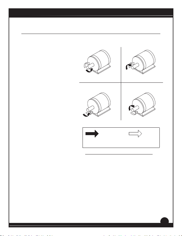
Most non-regenerave,
variable speed, DC drives
control current ow to a
motor in one direcon.
The direcon of current
ow is the same direcon
as the motor rotaon.
Non-regenerave drives
operate in Quadrant I,
and also in Quadrant III if
the drive is reversible (see
Figure 1). Motors must stop
before reversing direcon.
Unless dynamic braking
is used, non regenerave
drives cannot decelerate a
load faster than coasng to a
lower speed.
Regenerative drives operate
in two addional quadrants:
Quadrant II and Quadrant
IV. In these quadrants,
motor torque is in the
opposite direcon of motor rotaon.
This allows regenerave drives to reverse a motor without contractors
or switches, to control an overhauling load, and to decelerate a load
faster than it would to coast to a lower speed.
Quadrant II
Quadrant III
MOTOR
ROTATION
NOTE: ARROWS IN SAME DIRECTION = MOTOR ACTION
ARROWS IN OPPOSITE DIRECTION = REGENERATIVE ACTION
Quadrant I
Quadrant IV
Figure 1. Four Quadrant Operaon
RGT Series
MOTOR
TORQUE
1
Page 8

RGT Series
Section 2. Specifications
Model
RGT310U
RGT310U-PCM
RGT300U
RGT300U-PCM
RGT400U
RGT400U-PCM
Line
Voltage
(VAC)
115 0 - 90 3.0 1/20 - 1/4
115 0 - 90 10.0* 1/4 - 1
230 0 - 180 10.0* 1/2 - 2
Armature
Voltage
Range (VDC)
Maximum
Armature
Current (ADC) HP Range
* Heat sink kit part number 223-0235 must be used when the connuous
current output is over 7 amps.
AC Line Voltage 115 or 230 VAC ± 10%, 50/60 Hz, single phase
DC Armature Voltage
with 115 VAC Line Voltage
with 230 VAC Line Voltage
Acceleraon Time Range 0.5 - 6 seconds
Deceleraon Time Range 0.5 - 6 seconds
Analog Input Range
0 to ± 10 VDC
Non -PCM models (signal must be isolated; S0 to S2)
-PCM models (NEG to POS)
Input Impedance (S0 to S2) 32K ohms
Form Factor 1.37 at base speed
Load Regulaon 1% base speed or beer
Speed Range 60:1
Vibraon 0.5G maximum (0 - 50 Hz)
1-5, 4-20, 10-50 mA or 0 to ± 250 VDC
0.1G maximum (> 50 Hz)
0 - 90 VDC
0 - 180 VDC
2
Page 9

RGT Series
Safety Cercaons UL/cUL Listed Equipment, File # E132235
Ambient Temperature Range 10°C - 55°C
CSA Cered Component, File # LR41380
3
Page 10
RGT Series
Section 3. Dimensions
8.90 [226]
8.38 [213]
1.86 [47]
0.92 [23]
C508 C509
C506 C507
SCR508
SCR507
SCR506
R506
SCR505
SCR504
R505
SCR503
SCR502
R504
SCR501
C501
AC VOLTAGE
L2
AC VOLTAGE
L1
MOV501
R502
C510
FU501
C505
C504
R503
P505
T504
TP01
C522
SO503
T503
INHIBIT
C511
T502
C520 C521
T501
C513
C519
-24V
SO502
R501
T505
COM +24V INH
C502
FUSE
C503
MOV502
AC VOLTAGE
AC VOLTAGE
DC VOLTAGE
EARTH GND
L2
L1
GND
A2
ACC-DEC
P504
MAX SPD
P503
REV TQ
C512
C514 C518
P502
FWD TQ
C517C516
P501
IR COMP
C515
60HZ50HZ+15V
SW501
IC501IC502
RB2
RB1
-15V
S3
S2
S0 S1
DC VOLTAGE
A1
3.53 [90]
4.75 [120]
ALL DIMENSIONS IN INCHES [MILLIMETERS]
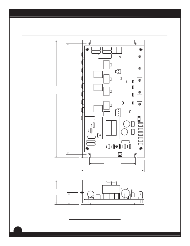
Figure 2. RGT Dimensions
4
Page 11
RGT Series
8.90 [226]
8.38 [213]
3.20 [81]
MOV501
AC VOLTAGE
L1
AC VOLTAGE
L2
C504
C505
FU501
4.75 [120]
3.53 [90]
FUSE
AC VOLTAGE
L1
AC VOLTAGE
L2
EARTH GND
GND
C503
DC VOLTAGE
A2
DC VOLTAGE
A1
S0 S1
C502
MOV502
IC501IC502
RB1
60HZ50HZ+15V
RB2
-15VS2S3
SW501
1.86 [47]
0.92 [23]
ALL DIMENSIONS IN INCHES [MILLIMETERS]
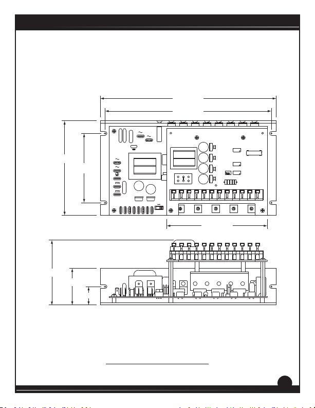
Figure 3. RGT-PCM Dimensions
C501
MAX
OUT
MIN
T505
COM+24V
INPUT VOLTAGE SELECT
115 230
FWD TQ REV TQ MAX SPD ACC-DECCOMP
OUT
1-5MA
10-50MA
4-20MA
SIGNAL
1 2 3
INPUT
ADJUST
COMPOL REVTPINPUT 2INPUT 1COM+15-15L2L1OUT2OUT1
121110987654321
5.21 [132]
5
Page 12
RGT Series
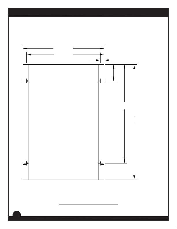
6.90 [175]
6.60 [168]
0.3 [8]
1.375 [35]
8.375 [213]
9.78 [249]
ALL DIMENSIONS IN INCHES [MILLIMETERS]
Figure 4. 223-0235 Dimensions
6
Page 13
Section 4. Installation
Do not install, rewire, or remove this control with input power
applied. Failure to heed this warning may result in re, explosion,
!
Heat Sinking
Models RGT300U, RGT300U-PCM, RGT400U, and RGT400U-PCM require
an addional heat sink when the connuous armature current is above 7
amps. Use Minarik Drives heat sink kit part number 223-0235. All other
chassis drives have sucient heat sinking in their basic conguraon.
Use a thermally conducve heat sink compound (such as Dow Corning®
340 Heat Sink Compound) between the chassis and the heat sink surface
for opmum heat transfer.
or serious injury. Make sure you read and understand the Safety
WARNING!
Precauons on page i before aempng to install this product.
RGT Series
7
Page 14

RGT Series
Mounng
• Drive components are sensitive to electrostatic discharge. Avoid
direct contact with the circuit board. Hold the drive by the chassis
or heat sink only.
• Protect the drive from dirt, moisture, and accidental contact.
• Provide sufficient room for access to the terminals and calibration
trim pots.
• Mount the drive away from heat sources. Operate the drive within
the specified ambient operating temperature range.
• Prevent loose connections by avoiding excessive vibration of the
drive.
• Mount the drive with its board in either a horizontal or vertical plane.
Six 0.19” (5 mm) wide slots in the chassis accept #8 pan head screws.
Fasten either the large base or the narrow flange of the chassis to
the subplate.
• The chassis should be earth grounded. Use a star washer beneath
the head of at least one of the mounting screws to penetrate the
anodized surface and to reach bare metal.
8
Page 15
Speed Adjust Potenometer
Be sure that the potenometer tabs do not make contact with the
!
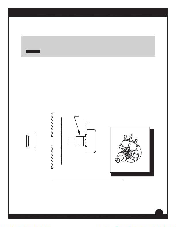
If using a remote potenometer with a chassis drive, mount the speed
adjust potenometer through a 0.38 in. (10 mm) hole with the hardware
provided (Figure 5). Install the circular insulang disk between the panel
and the 10K ohm speed adjust potenometer.
Twist the speed adjust potenometer wire to avoid picking up unwanted
electrical noise. If the speed adjust potenometer wires are longer than
18 in. (46 cm), use shielded cable. Keep the speed adjust potenometer
wires separate from power leads (L1, L2, A1, A2).
NUT
potenometer’s body. Grounding the input will cause damage to
WARNING!
the drive.
MOUNT THROUGH A 0.38 IN. (10 MM) HOLE
STAR
WASHER
INSULATING DISK
PANEL
SPEED ADJUST
POTENTIOMETER
CW
POT TAB ASSIGNMENTS
RGT Series
WIPER
CCW
Figure 5. Speed Adjust Potenometer
9
Page 16
RGT Series
Wiring
Do not install, rewire, or remove this control with input power
applied. Failure to heed this warning may result in re, explosion,
!
• Use 18 - 24 AWG wire for logic wiring. Use 14 - 16 AWG wire for
or serious injury.
WARNING!
Circuit potenals are at 115 or 230 VAC above ground. To prevent
the risk of injury or fatality, avoid direct contact with the printed
circuit board or with circuit elements.
Do not disconnect any of the motor leads from the drive unless
power is removed or the drive is disabled. Opening any one
motor lead while the drive is running may destroy the drive.
This product does not have internal solid state motor overload
protecon. It does not contain speed-sensive overload
protecon, thermal memory retenon or provisions to receive
and act upon signal from remote devices for over temperature
protecon. If motor over protecon is needed in the end-use
product, it needs to be provided by addional equipment in
accordance with NEC standards.
AC line and motor wiring.
10
Page 17
Shielding Guidelines
Under no circumstances should power and logic level leads be
!
As a general rule, Minarik Drives recommends shielding of all conductors.
If it is not praccal to shield power conductors, it is recommended
to shield all logic-level leads. If shielding of all logic-level leads is not
praccal, the user should twist all logic leads with themselves to
minimize induced noise.
It may be necessary to earth ground the shielded cable. If noise is
produced by devices other than the drive, ground the shield at the drive
end. If noise is generated by a device on the drive, ground the shield at
the end away from the drive. Do not ground both ends of the shield.
If the drive connues to pick up noise aer grounding the shield, it may
be necessary to add AC line ltering devices, or to mount the drive in a
less noisy environment.
Logic wires from other input devices, such as moon controllers and PLL
velocity controllers, must be separated from power lines in the same
manner as the logic I/O on this drive.
bundled together. Induced voltage can cause unpredictable
behavior in any electronic device, including motor controls.
WARNING!
RGT Series
11
Page 18

RGT Series
Line Fusing
Drives should be fused for protecon. Use fast acng fuses rated for 250
VAC or higher and 150% of maximum armature current. Fuse HOT L1
only when the line voltage is 115 VAC. Fuse both L1 and L2 when the line
voltage is 230 VAC. Table 1 lists the recommended line fuse sizes.
Table 1. Recommended Line Fuse Sizes
90 VDC
Motor
Horsepower
1/20
1/15
1/8
1/6
1/4 1/2 2.5 5
1/3
1/2
3/4
1
Minarik Drives oers fuse kits. See Secon 9: Accessories and
Replacement Parts for fuse kit part numbers.
180 VDC
Motor
Horsepower
1/10
1/8
1/4
1/3
3/4
1
2
Maximum DC
Armature Current
(amps)
0.5
0.8
1.5
1.7
3.5
5.0
7.5
10
AC Line
Fuse Size
(amps)
1
1.5
3
3
8
10
15
15
12
Page 19
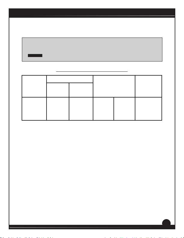
Short Circuit Current Rang (SCCR)
Short-circuit current rang (SCCR) is the maximum short-circuit
!
Drive Model
RGT400U 10,000 240 V
current that the speed control can safely withstand when
protected by a specic over-current protecve device(s).
WARNING!
Table 2. Short Circuit Current Rangs
Short Circuit Current Rang
Maximum
Current, kA
Maximum
Voltage, V
Types of Branch
Circuit Protection
Non-time
Delay
K5 Fuse
Inverse
Time
Circuit
Breaker
RGT Series
Maximum
Rating of
Overcurrent
Protection
30 A
13
Page 20
RGT Series
Connecons
Do not connect this equipment with power applied. Failure to
!
Power Input
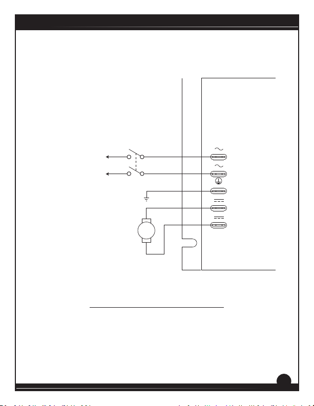
Connect the AC line power leads to terminals L1 and L2. Minarik Drives
recommends the use of a single-throw, double-pole master power
switch. The switch should be rated at a minimum of 250 volts and 200%
of motor current. Refer to Figure 6 on page 15.
Motor
Drives supply motor armature voltage from A1 and A2 terminals. It is
assumed throughout this manual that, when A1 is posive with respect
to A2, the motor will rotate clockwise (CW) while looking at the output
sha protruding from the front of the motor. If the motor does not
spin in the desired direcon, remove power and reverse the A1 and A2
connecons.
Connect a DC motor to terminals A1 and A2. Refer to Figure 6 on page
15. Ensure that the motor voltage rang is consistent with the drive’s
output voltage.
heed this warning may result in re, explosion, or serious injury.
WARNING!
Minarik Drives strongly recommends the installaon of a
master power switch in the voltage input line, as shown in
Figure 6 (page 15). The switch contacts should be rated at a
minimum of 200% of motor nameplate current and 250 volts.
14
Page 21
AC LINE VOLTAGE INPUT
115 VAC (RGT300U/RGT310U)
230 VAC (RGT400U)
MASTER
POWER SWITCH
EARTH
GROUND
MOTOR
GND
AC VOLTAGE
L1
AC VOLTAGE
L2
EARTH GND
DC VOLTAGE
A2
DC VOLTAGE
A1
Figure 6. Power and Motor Connecons
RGT Series
15
Page 22
RGT Series
Speed Adjust Potenometer
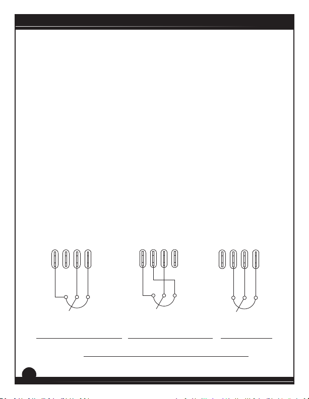
Use a 10K ohm, 1/4 W potenometer for speed control. The motor can
operate in one direcon (unidireconal) or two direcons (bidireconal)
depending on how the speed adjust potenometer is connected to the
drive.
For unidireconal operaon in the foward direcon, connect the speed
adjust potenometer as shown in Figure 7(a).
For unidireconal operaon in the reverse direcon, connect the speed
adjust potenometer as shown in Figure 7(b).
For bidireconal operaon, connect the speed adjust potenometer
as shown in Figure 7(c). The motor does not operate when the
potenometer is in the center posion. Turning the potenometer
clockwise (CW) from the center posion causes the motor to rotate in
the forward direcon, while turning the potenometer counterclockwise
(CCW) causes rotaon in the reverse direcon.
S0 S1
S2
10K OHM
SPEED ADJUST
POTENTIOMETER
S3
CW
S0 S1
S3
S2
10K OHM
SPEED ADJUST
POTENTIOMETER
CW
(a) Unidireconal Forward (b) Unidireconal Reverse
Figure 7. Speed Adjust Potenometer Connecons
16
S0 S1
POTENTIOMETER
S3
S2
10K OHM
SPEED ADJUST
(c) Bidireconal
CW
Page 23
Analog Input Signal (non -PCM models)
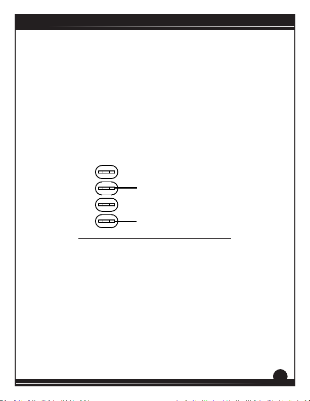
Instead of using a speed adjust potenometer, the drive may be wired to
follow an analog input voltage signal that is isolated from earth ground
(Figure 8). Connect the signal common (–) S0. Connect the signal input
(+) to S2. A potenometer can be used to scale the analog input voltage.
An interface device, such as Minarik Drives model PCM4, may be used to
scale and isolate an analog input voltage.
An analog input voltage range of -10 to 10 VDC is required to produce
an armature voltage range of -90 to 90 VDC with 115 VAC line voltage or
-180 to 180 VDC with 230 VAC line voltage.
SIGNAL INPUT (+)
RGT Series
S0 S1 S2 S3
SIGNAL COMMON (-)
Figure 8. RGT Analog Input Signal Connecons
17
Page 24
1 2 3
OUT
MIN
OUT
MAX
10-50MA
4-20MA
1-5MA
ADJUST
INPUT
SIGNAL
COM
T505
C501
RGT Series
Analog Input Signal (RGT-PCM models)
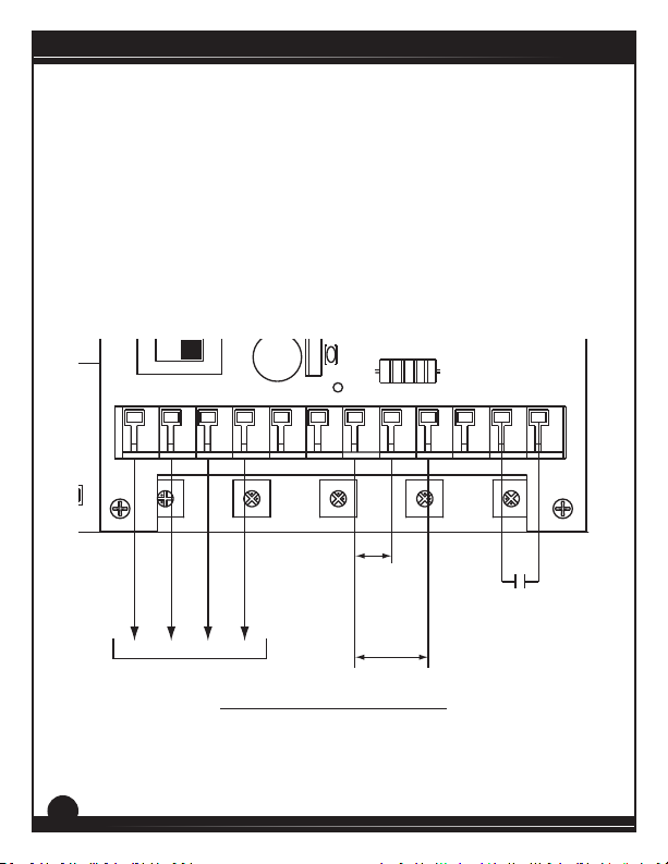
Instead of using a speed adjust potenometer, the drive may be wired
to follow an analog input voltage signal that is isolated or non-isolated
(Figure 9). Connect the signal common (–) to terminal 7 (COM). Connect
the signal input (+) to terminal 8 (INPUT 1) is using an analog current
signal or a voltage signal less than 25 VDC, otherwise connect to terminal
9 (INPUT 2). A potenometer can be used to scale the analog input
voltage.
Acceptable analog input ranges are 1 -5 mA, 4 - 20 mA, 10 - 50 mA, and
any voltage range less than 250 VDC.
+24V
INPUT VOLTAGE SELECT
TO S2
115 230
TO S0
TO L1
FWD TQ REV TQ MAX SPD ACC-DECCOMP
TO L2
± 25VDC
1 - 5 mA
4 - 20 mA
10 - 50 mA
Direction
Switch
COMPOL REVTPINPUT 2INPUT 1COM+15-15L2L1OUT2OUT1
121110987654321
PREWIRED CONNECTIONS
18
± 250VDC
Figure 9. RGT-PCM Connecons
Page 25

Direcon Switch
For RGT models, refer to page 35 for wiring a direcon switch.
For RGT-PCM models, a single-pole, single-throw switch can be used as
a reversal switch. Connect the switch to terminals 11 (POL REV) and 12
(COM). Close the switch to reverse the motor. Open the switch to return
the motor back to it’s original direcon. Refer to Figure 9 on page 18.
Regen Brake and Inhibit
See the “Starng and Stopping Methods” secon on pages 24 through 26
for a detailed descripon of the Inhibit and Regen Braking connecons.
RGT Series
19
Page 26
RGT Series
Section 5. Operation
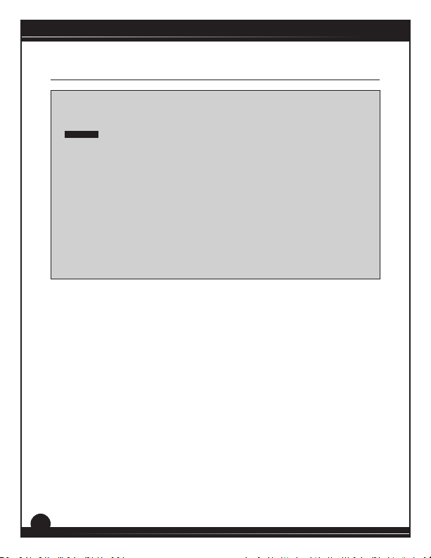
Change voltage switch sengs only when the drive is
disconnected from AC line voltage. Make sure both switches are
!
Before Applying Power
set to their correct posion. If the switches are improperly set
to a lower voltage posion, the motor will not run at full voltage
WARNING!
and may cause damage to the transformer. If the switches are
improperly set to a higher voltage posion, the motor will
overspeed, which may cause motor damage, or result in bodily
injury or loss of life.
Dangerous voltages exist on the drive when it is powered. BE
ALERT. High voltages can cause serious or fatal injury. For your
safety, use personal protecve equipment (PPE) when operang
this drive.
If the motor or drive does not perform as described, disconnect
the AC line voltage immediately. Refer to the Troubleshoong
secon, page 44, for further assistance.
1. Verify that no foreign conductive material is present on the
printed circuit board.
2. Ensure that all switches are properly set.
20
Page 27
Select Switches
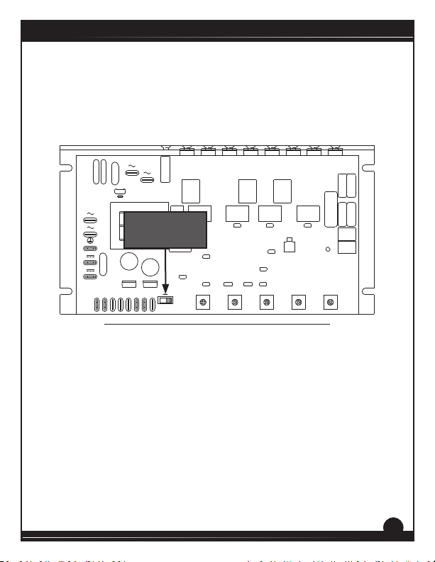
Line Frequency Select (SW501)
Set the line frequency select switch to 60 HZ if the line frequency is 60 Hz
or to 50 HZ if the line frequency is 50 Hz. See Figure 10.
SCR503
SCR504
SCR506
C520 C521
C517C516
P502
FWD TQ
R505
T502
C514 C518
SCR505
C512
P503
REV TQ
SCR507
R506
T503
C522
SO503
INHIBIT
C511
P504
MAX SPD
SCR501
SCR502
MOV501
AC VOLTAGE
L1
C504
C505
FUSE
AC VOLTAGE
L1
AC VOLTAGE
L2
EARTH GND
GND
C503
DC VOLTAGE
MOV502
A2
DC VOLTAGE
A1
S0 S1
-15V
S3
S2
C501
AC VOLTAGE
L2
FU501
R501
Line Frequency
T505
SO502
Select (SW501)
COM +24V INH
C502
C515
IC501IC502
RB1
+15V
RB2
50HZ
60HZ
SW501
R504
T501
C519
-24V
C513
P501
IR COMP
Figure 10. Line Frequency Select Switch Locaon
RGT Series
SCR508
C506 C507
C510
C508 C509
T504
R502
R503
TP01
P505
ACC-DEC
21
Page 28
RGT Series
Select Switches (-PCM models)
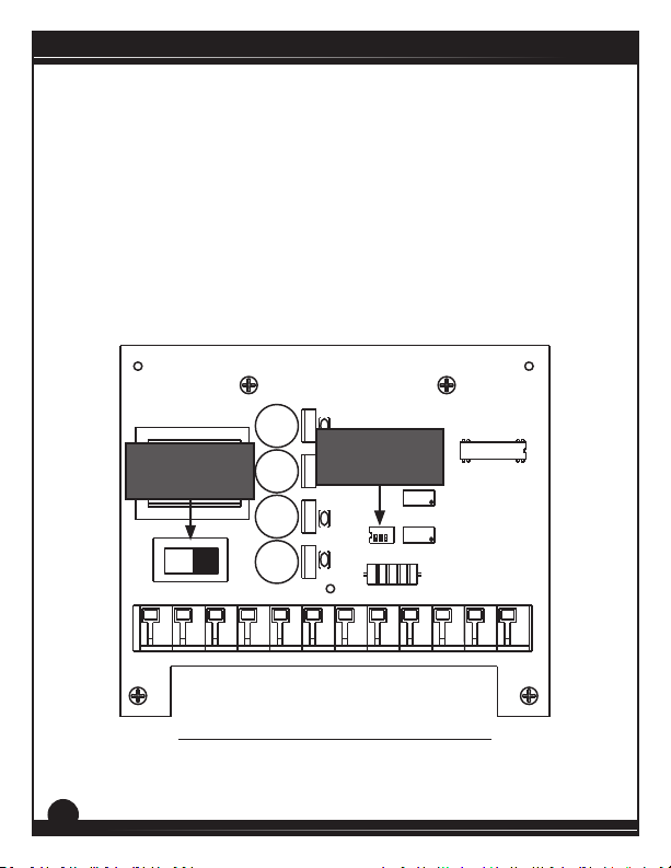
Analog Input Signal Select (SW501)
Set the analog input signal select switch SW501 to match the appropriate
input signal. See Figure 11 for locaon and Table 3 on page 33 for
conguraon.
AC Line Voltage Select (SW502)
Set the input voltage select switch SW502 to either 115 or 230 to match
the AC line voltage. See Figure 11.
MAX
OUT
MIN
OUT
1-5MA
10-50MA
4-20MA
SIGNAL
1 2 3
INPUT
ADJUST
AC Line Voltage
Select (SW502)
INPUT VOLTAGE SELECT
115 230
Analog Input Signal
Select (SW501)
COMPOL REVTPINPUT 2INPUT 1COM+15-15L2L1OUT2OUT1
121110987654321
Figure 11. RGT-PCM Select Switch Locaons
22
Page 29

RGT Series
Startup
1. Turn the speed adjust potentiometer or input voltage signal to
minimum speed.
2. Apply AC line voltage.
3. Slowly advance the speed adjust potentiometer clockwise
(CW) or increase the input voltage signal. The motor slowly
accelerates as the potentiometer is turned CW or as the input
voltage signal is increased. Continue until the desired speed is
reached.
4. Remove AC line voltage from the drive to coast the motor to a
stop.
23
Page 30

RGT Series
Starng and Stopping Methods
Regenerave braking, coasng to a stop, or decelerang to
minimum speed is recommended for frequent starts and stops.
!
Automac Restart Upon Power Restoraon
All drives automacally run to set speed when power is applied and the
Regen Brake and Inhibit are open.
Line Starng and Stopping
Line starng and stopping (applying and removing AC line voltage) is
recommended for infrequent starng and stopping of a drive only. When
AC line voltage is applied to the drive, the motor accelerates to the speed
set by the speed adjust potenometer or analog signal. When AC line
voltage is removed, the motor coasts to a stop.
Do not use any of these methods for emergency stopping. They
WARNING!
may not stop a drive that is malfunconing. Removing AC line
power (both lines) is the only acceptable method for emergency
stopping.
For this reason, Minarik Drives strongly recommends installing
an emergency stop switch on both AC line inputs (see Figure 6
on page 15).
Frequent starng and stopping can produce high torque. This
may cause damage to motors, especially gearmotors that are not
properly sized for the applicaon.
24
Page 31
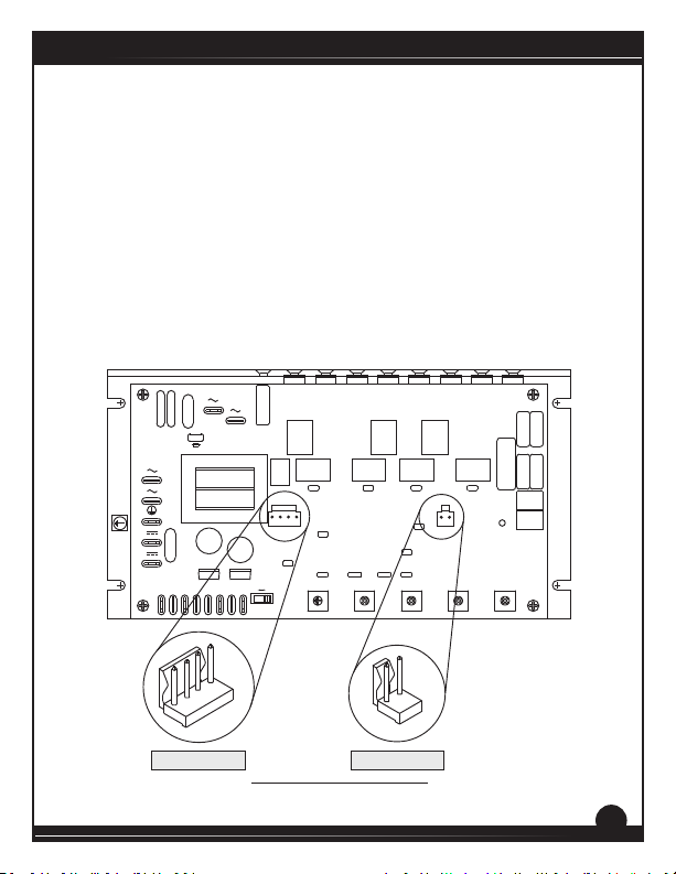
Inhibit - Regenerave Brake to Zero Speed
Short the inhibit terminals to regeneravely brake the motor to zero
speed (see Figure 12). The inhibit bypasses the deceleraon rate set by
the ACC-DEC trim pot. Open the inhibit terminals to accelerate the motor
to set speed.
Twist inhibit wires and separate them from power-carrying wires or
sources of electrical noise. Use shielded cable if the inhibit wires are
longer than 18 inches (46 cm). If shielded cable is used, ground only one
end of the shield to earth ground. Do not ground both ends of the shield.
SO502 terminals are installed for future interfaces. Leave the factory
installed jumper (INH and -24 terminals) in place.
RGT Series
C504
AC VOLTAGE
L1
AC VOLTAGE
L2
EARTH GND
GND
DC VOLTAGE
A2
DC VOLTAGE
A1
MOV501
AC VOLTAGE
L1
C505
FU501
FUSE
C503
MOV502
S0 S1
-15VS2S3
COM +24V INH -24
SO502 TERMINALS
SCR501
SCR502
C501
AC VOLTAGE
L2
RB1
RB2
R504
R501
T501
T505
C519
SO502
-24V
COM +24V INH
C502
IC501IC502
C513
C515
P501
60HZ50HZ+15V
SW501
IR COMP
Figure 12. Inhibit Switch
SCR505
SCR504
SCR503
R505
T502
C520 C521
C512
C517C516
C514 C518
P502
P503
FWD TQ
REV TQ
FWD TQIR COMP REV TQ MAX SPD ACC-DEC
SCR507
SCR506
R506
T503
C522
SO503
INHIBIT
C511
P504
MAX SPD
INHIBIT
INHIBIT TERMINALS
SCR508
C506 C507
C510
C508 C509
T504
R502
R503
TP01
P505
ACC-DEC
25
Page 32
RGT Series
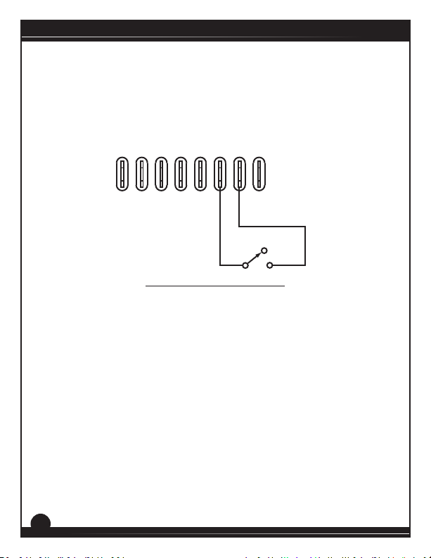
Regen Brake - Regenerave Decel to Zero Speed
Short the regen brake terminals RB1 and RB2 to regeneravely brake
the motor to zero speed (see Figure 13). The regen brake decelerates at
a rate set by the ACC-DEC trim pot. Open the regen brake terminals to
accelerate the motor to set speed.
S0 S1
S2
Figure 13. Regen Brake Switch
RB1
+15V
RB2
-15V
S3
RUN
STOP
26
Page 33
Section 6. Calibration
Dangerous voltages exist on the drive when it is powered. When
possible, disconnect the voltage input from the drive before
!
RGT series drives have user-adjustable trim pots. Each drive is factory
calibrated to its maximum current rang. Readjust the calibraon trim
pot sengs to accommodate lower current rated motors.
All adjustments increase with CW rotaon, and decrease with CCW
rotaon. Use a non-metallic screwdriver for calibraon. Each trim pot is
idened on the printed circuit board.
adjusng the trim pots. If the trim pots must be adjusted with
WARNING!
power applied, use insulated tools and the appropriate personal
protecon equipment. BE ALERT. High voltages can cause serious
or fatal injury.
RGT Series
27
Page 34

RGT Series
Maximum Speed (MAX SPEED)
The MAX SPD seng determines the maximum motor speed when the
speed adjust potenometer or input voltage signal is set for maximum
speed.
To calibrate MAX SPD:
1. Set the MAX SPD trim pot full CCW.
2. Set the speed adjust potentiometer or input voltage signal for
maximum speed.
3. Adjust MAX SPD until the desired maximum speed is reached.
If using a -PCM model, set the MAX SPD trim pot fully CW.
Acceleraon-Deceleraon (ACC-DEC)
The ACC-DEC trim pot seng determines the me the motor takes to
accelerate to a higher speed or decelerate to a lower speed within the
limits of available torque. ACC-DEC is set for its fastest acceleraon and
deceleraon me (full CCW).
Turn the ACC-DEC trim pot CW to increase the acceleraon and
deceleraon me, or CCW to decrease the acceleraon and
deceleraon me.
28
Page 35
Forward Torque (FWD TQ)
FWD TQ should be set to 120% of motor nameplate current
rang. Connuous operaon beyond this rang may damage the
!
The FWD TQ seng determines the maximum torque for accelerang
and driving the motor in the forward direcon. To calibrate FWD TQ,
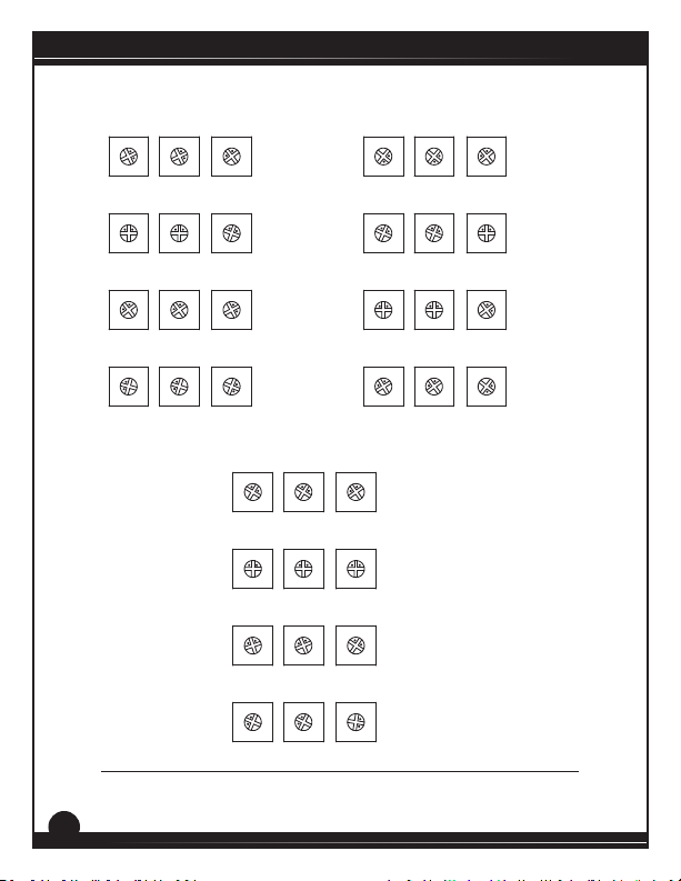
refer to the recommended FWD TQ sengs in Figure 14 on page 32 or
use the following procedure:
motor. If you intend to operate beyond the rang, contact your
WARNING!
Minarik Drives representave for assistance.
1. With the power disconnected from the drive, connect a DC
ammeter in series with the armature.
2. Set the FWD TQ trim pot to minimum (full CCW).
3. Set the speed adjust potentiometer full CW or input voltage
signal to maximum speed.
4. Carefully lock the motor armature. Be sure that the motor is
firmly mounted.
5. Apply line power. The motor should be stopped.
6. Slowly adjust the FWD TQ trim pot CW until the armature
current is 120% of motor rated armature current.
7. Turn the speed adjust potentiometer CCW or decrease the
input voltage signal.
8. Remove line power.
9. Remove the stall from the motor.
10. Remove the ammeter in series with the motor armature if it is
no longer needed.
RGT Series
29
Page 36
RGT Series
Reverse Torque (REV TQ)
REV TQ should be set to 120% of motor nameplate current rang.
Connuous operaon beyond this rang may damage the motor.
!
The REV TQ seng determines the maximum torque for accelerang and
driving the motor in the reverse direcon. To calibrate REV TQ, refer to
the recommended REV TQ sengs in Figure 14 on page 32 or use the
following procedure:
If you intend to operate beyond the rang, contact your Minarik
WARNING!
Drives representave for assistance.
1. With the power disconnected from the drive, connect a DC
ammeter in series with the armature.
2. Set the REV TQ trim pot to minimum (full CCW).
3. Set the speed adjust potentiometer full CW or input voltage
signal to maximum speed.
4. Carefully lock the motor armature. Be sure that the motor is
firmly mounted.
5. Apply line power. The motor should be stopped.
6. Slowly adjust the REV TQ trim pot CW until the armature
current is 120% of motor rated armature current.
7. Turn the speed adjust potentiometer CCW or decrease the
input voltage signal.
8. Remove line power.
9. Remove the stall from the motor.
10. Remove the ammeter in series with the motor armature if it is
no longer needed.
30
Page 37

IR Compensaon (IR COMP)
The IR COMP seng determines the degree to which motor speed is held
constant as the motor load changes.
Use the following procedure to recalibrate the IR COMP seng:
1. Set the IR COMP trim pot to minimum (full CCW).
2. Increase the speed adjust potentiometer or input voltage signal
until the motor runs at midspeed without load (for example,
900 RPM for an 1800 RPM motor). A handheld tachometer may
be used to measure motor speed.
3. Load the motor armature to its full load armature current
rating.The motor should slow down.
4. While keeping the load on the motor, rotate the IR COMP trim
pot until the motor runs at the speed measured in step 2. If
the motor oscillates (overcompensation), the IR COMP trim pot
may be set too high (CW). Turn the IR COMP trim pot CCW to
stabilize the motor.
5. Unload the motor.
See Figure 14 on page 32 for recommended IR COMP sengs.
RGT Series
31
Page 38
RGT Series
RGT310URGT300U
1 HP
90 VDC
FWD TQ
FWD TQ
FWD TQ
FWD TQ
REV TQ
REV TQ
REV TQ
REV TQ
IR COMP
IR COMP
IR COMP
IR COMP
10 ADC
3/4 HP
90 VDC
7.0 ADC
1/2 HP
90 VDC
5 ADC
1/4 HP
90 VDC
2.7 ADC
FWD TQ
FWD TQ
FWD TQ
FWD TQ
REV TQ
REV TQ
REV TQ
REV TQ
IR COMP
IR COMP
IR COMP
IR COMP
RGT400U
2 HP
180 VDC
FWD TQ
FWD TQ
FWD TQ
FWD TQ
REV TQ
REV TQ
REV TQ
REV TQ
IR COMP
IR COMP
IR COMP
IR COMP
9.2 ADC
1 1/2 HP
180 VDC
7.5 ADC
1 HP
180 VDC
5 ADC
3/4 HP
180 VDC
3.8 A ARM
Figure 14. Recommended FWD TQ, REV TQ, and IR COMP Sengs
(actual sengs may vary with each applicaon)
32
1/4 HP
90 VDC
2.1 ADC
1/8 HP
90 VDC
1.3 ADC
1/15 HP
90 VDC
0.75 ADC
1/20 HP
90 VDC
0.56 ADC
Page 39
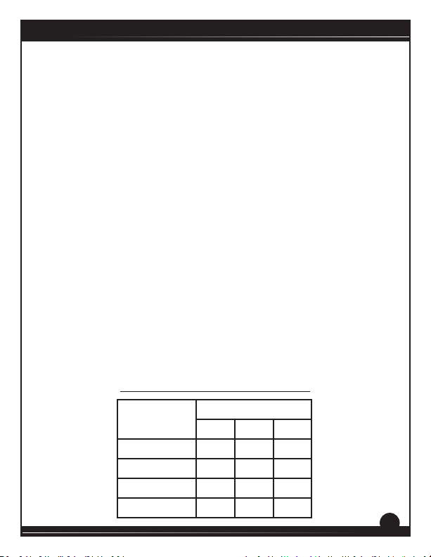
Input Signal Calibraon with -PCM Models
The following values should be known:
S
- Minimum analog input signal (e.g. 0 VDC or 4 mA)
min
S
- Maximum analog input signal (e.g. 10 VDC or 20 mA)
max
O
- Minimum output voltage signal to base RGT unit (typically 0 VDC)
min
O
- Maximum output voltage signal to base RGT unit (typically 10 VDC)
max
For example, if using a 4-20 mA signal and you wanted to run the motor
from 0 RPM to full RPM, your values would be;
S
= 4 O
min
S
= 20 O
max
O
and O
min
and 2).Use a voltmeter for voltage measurements and an ammeter for
current measurements.
Calibraon Procedure
1. Set the SW501 DIP switches to the following posions based on the
input signal to be used.
are measured between OUT1 and OUT2 (terminals 1
max
Table 3. DIP Switch SW501 Conguraons
Input Signal
4 - 20 mA OFF ON OFF
10 - 50 mA OFF OFF ON
= 0
min
= 10
max
DIP Switch Settings
Range
VDC OFF OFF OFF
1 - 5 mA ON OFF OFF
1 2 3
RGT Series
33
Page 40

RGT Series
2. Connect (but do not power) the input signal as follows.
- Connect the signal negave (-) to COM (terminal 7).
- If using a current signal or voltage signal up to 25 VDC, connect
- the signal posive to INPUT 1 (terminal 8).
- If using a signal greater than 25 VDC, connect the signal posive (+)
- to INPUT 2 (terminal 9).
3. Set the MAX SPD trim pot on the RGT unit fully CCW.
4. Apply both the AC line voltage and the minimum analog input signal.
5. Adjust the MIN OUT trim pot so that the output voltage between
terminals 1 and 2 (OUT1 and OUT2) is O
min
.
6. Set the input signal to it’s max, S
7. Calculate the test point voltage, Vtp.
S
* m
Vtp = where m =
8. Adjust the SIGNAL INPUT ADJ trim pot so that the voltage between
COM (terminal 7) and TP (terminal 10) is Vtp.
9. Adjust the MAX OUT trim pot so that the output voltage between
terminals 1 and 2 (OUT1 and OUT2) is O
10. Repeat steps 4, 5, 6, 8, and 9. Use the same values that you previously
calculated.
34
min
2
max
.
max
O
- O
max
min
S
- S
max
min
.
Page 41
Section 7.Application Notes
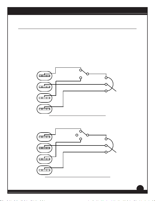
Direcon Switch
For a Forward/Reverse switch, use a single-pole, two-posion switch
with a single speed adjust potenometer to regeneravely reverse the
motor (Figure 15). If a Forward/Stop/Reverse switch is desired, use a
single-pole, three-posion switch (Figure 16).
REVERSE
FORWARD
10K POTENTIOMETER
S0 S1 S2 S3
Figure 15. Forward-Reverse Switch
REVERSE
STOP
FORWARD
10K POTENTIOMETER
RGT Series
S0 S1 S2 S3
Figure 16. Forward-Stop-Reverse Switch
35
Page 42

RGT Series
Mulple Fixed Speeds
Replace the speed adjust potenometer with a series of resistors with a
total series resistance of 10K ohms (Figure 17). Add a single pole, mulposion switch with the correct number of posions for the desired
number of xed speeds.
R1
S1 or S3
S2
S0
Figure 17. Mulple Fixed Speeds
R4
R2
TOTAL SERIES
RESISTANCE
R3
10K OHMS
36
Page 43
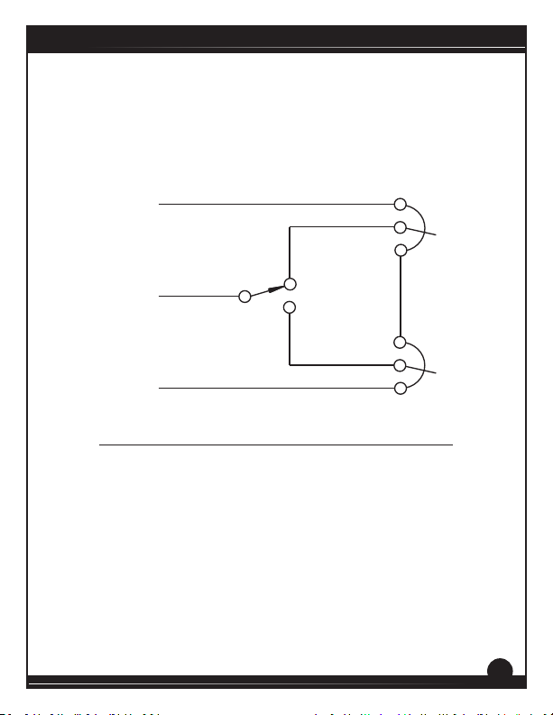
Adjustable Speeds Using Potenometers In Series
Replace the speed adjust potenometer with a series of resistors with a
total series resistance of 10K ohms (Figure 18). Add a single pole, mulposion switch with the correct number of posions for the desired
number of xed speeds.
S3
or S1
HIGH
SPEED
S2
LOW
SPEED
RGT Series
CW
5K
OHM
CW
S0
Figure 18. Adjustable Speeds Using Potenometers In Series
5K
OHM
37
Page 44
RGT Series
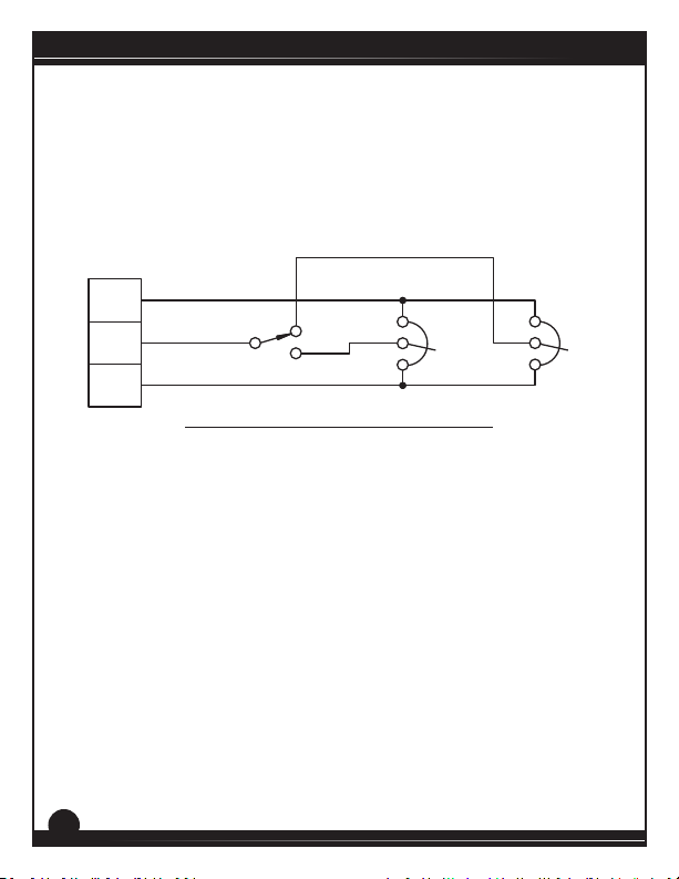
Independent Adjustable Speeds
Replace the speed adjust potenometer with a single pole, mulposion switch, and two or more potenometers in parallel, with a total
parallel resistance of 10K ohms. Figure 19 shows the connecon of two
independent speed adjust potenometers that can be mounted at two
separate operang staons.
S1 or S3
S2
SPEED 2
SPEED 1
S0
Figure 19. Independent Adjustable Speeds
CW CW
20K
OHM
20K
OHM
38
Page 45
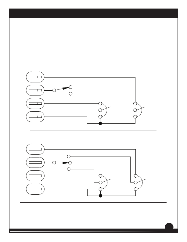
Independent Adjustable Forward and Reverse Speeds
Replace the speed adjust potenometer with a single pole, mul-posion
switch, and two or more potenometers in parallel, with a total parallel
resistance of 10K ohms. Figures 20 and 21 show the connecon of two
independent forward and reverse speed adjust potenometers that can
be mounted at two separate operang staons.
FORWARD
RGT Series
REVERSE
S0 S1 S2 S3
CW
10K
OHM
CW
10K
OHM
Figure 20. Independent Adjustable Forward and Reverse Speeds
FORWARD
STOP
REVERSE
S0 S1 S2 S3
CW
10K
OHM
CW
10K
OHM
Figure 21. Independent Adjustable Forward and Reverse Speeds with Stop
39
Page 46
RGT Series
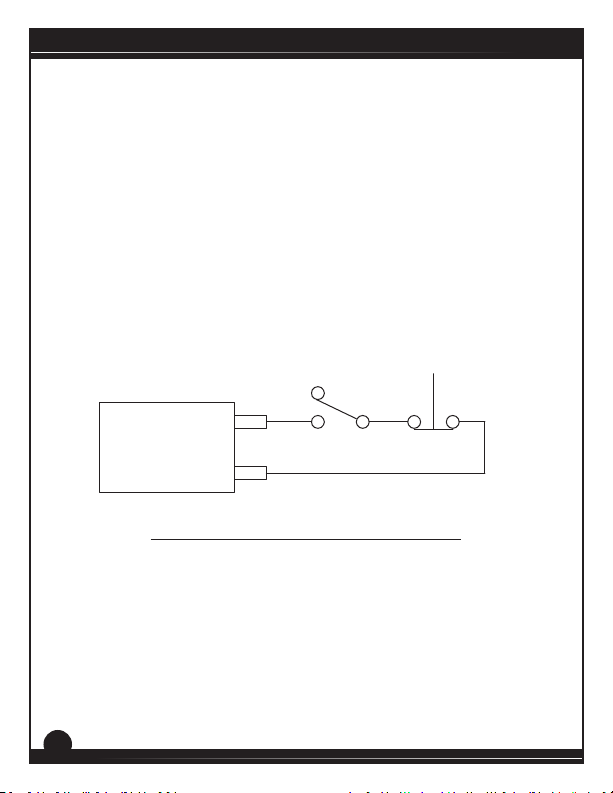
RUN/JOG Switch - Inhibit Connecon
Use a single pole, two posion switch for the RUN/JOG switch, and a
single pole, normally closed, momentary operated pushbuon for the
JOG pushbuon.
Connect the RUN/JOG switch and JOG pushbuon to the inhibit terminals
as shown in Figure 22. The motor coasts to a stop when the RUN/JOG
switch is set to JOG. Press the JOG pushbuon to jog the motor. Return
the RUN/JOG switch to RUN for normal operaon.
JOG
RUN
PUSHBUTTON
INHIBIT
Figure 22. RUN/JOG Switch - Inhibit Connecon
40
JOG
Page 47
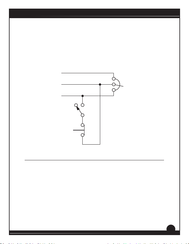
RUN/JOG Switch - Potenometer Connecon
Connect the RUN/JOG switch and the JOG pushbuon as shown in Figure
23. When the RUN/JOG switch is set to JOG, the motor decelerates to
zero speed. Press the JOG pushbuon to jog the motor. Return the RUN/
JOG switch to RUN for normal operaon.
RGT Series
S1 or S3
PUSHBUTTON
S2
SO
JOGRUN
JOG
CW
10K OHM
SPEED ADJUST
POTENTIOMETER
Figure 23. RUN/JOG Switch - Speed Adjust Potenometer Connecon
41
Page 48
RGT Series
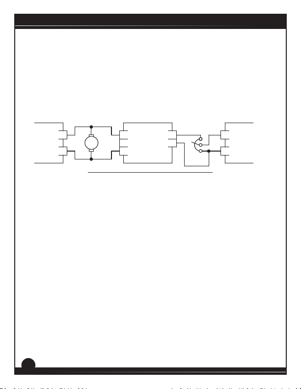
Leader-Follower Applicaon
In this applicaon, use a PCM4 to monitor the speed of the leader motor
(Figure 24). The PCM4 isolates the leader motor from the follower
drive, and outputs a voltage proporonal to the leader motor armature
voltage. The follower drive uses this voltage reference to set the speed of
the follower motor. An oponal rao potenometer may be used to scale
the PCM4 output voltage.
(+)
Leader
Drive
9
A1
MOTOR
A2
8
7
(+)
PCM4
(-)
TB501
Figure 24. Leader-Follower Applicaon
TB502
2
1 (-)
10K Ohm
(optional)
S2
Follower
Drive
S0
42
Page 49
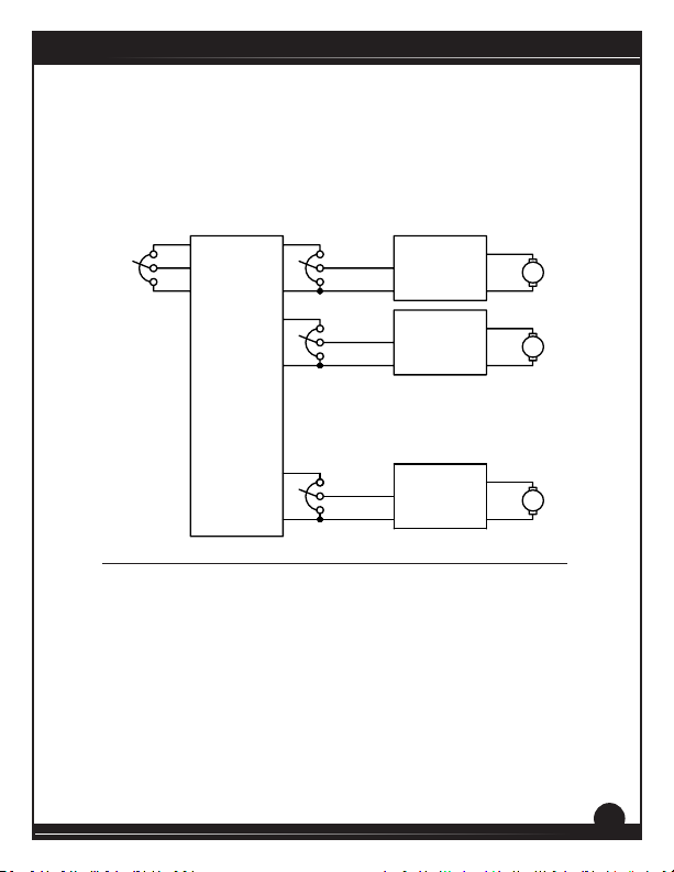
Single Speed Potenometer Control Of Mulple Drives
Mulple drives can be controlled with a single speed adjust potenometer
using a USIM-8 at the input of each drive to provide isolaon (Figure 25).
Oponal rao potenometers can be used to scale the USIM-8 output
voltage, allowing independent control of each drive.
ratio pot A
(optional )
10K Ohms
ratio pot B
(optional)
10K Ohms
ratio pot H
(optional)
10K Ohms
A1
Drive
S2
A
Drive
Drive
A2
A1
B
A2
A1
H
A2
S0
S2
S0
S2
S0
10K Ohms
S3
S2
S1
+
1
-
+
2
-
USIM-8
+
8
-
Figure 25. Single Speed Potenometer Control of Mulple Drives
RGT Series
r
Mot o
A
Mot o
r
B
Mot o
r
H
43
Page 50
RGT Series
Section 8. Troubleshooting
Dangerous voltages exist on the drive when it is powered. When
possible, disconnect the drive while troubleshoong. High
!
Before Troubleshoong
Perform the following steps before starng any procedure in this
section:
For addional assistance, contact your local Minarik Drives distributor
or the factory direct:
voltages can cause seroius or fatal injury.
WARNING!
1. Disconnect AC line voltage from the drive.
2. Check the drive closely for damaged components.
3. Check that no conductive or other foreign material has become
lodged on the printed circuit board.
4. Verify that every connection is correct and in good condition.
5. Verify that there are no short circuits or grounded connections.
6. Check that the drive’s rated armature is consistent with the
motor ratings.
(800) MINARIK or FAX: (800) 394-6334
44
Page 51

PROBLEM POSSIBLE CAUSE SUGGESTED SOLUTIONS
Line fuse
blows.
Line fuse does
not blow, but
the motor does
not run.
Motor does not
stop when the
1. Line fuse is the wrong size. 1. Check that the line fuse is
2. Motor cable or armature is
shorted to ground.
3. Nuisance tripping caused by
a combination of ambient
conditions and high-current
spikes (i.e. reversing).
1. Speed adjust potentiometer
or input voltage signal is set
to zero speed.
2. Inhibit is active. 2. Remove the short from the
4. Drive is in current limit. 4. Verify that the motor is not
5. Drive is not receiving AC line
voltage.
6. Motor is not connected. 6. Remove power. Connect the
1. Noise on logic wires. 1. Place a .01 μF capacitor across
correct for the motor size.
2. Check motor cable and
armature for shorts.
3. Add a blower to cool the drive
components, decrease FWD
TQ / REV TQ settings, resize
motor and drive for actual
load demand, or check for
incorrectly aligned mechanical
components or “jams”. See
pages 29 or 30 for information
on adjusting the FWD TQ / REV
TQ trim pots.
1. Increase the speed adjust
potentiometer setting or input
voltage signal.
inhibit terminals
jammed. Increase FWD TQ /
REV TQ setting if set too low.
5. Apply AC line voltage.
motor to A1 and A2. Reapply
power.
terminals S0 and S2.
speed adjust
potenometer
is full CCW.
RGT Series
45
Page 52

RGT Series
Motor runs in
the opposite
direcon
Motor runs too
fast.
Motor will
not reach the
desired speed.
PROBLEM POSSIBLE CAUSE SUGGESTED SOLUTIONS
1. Motor connections to A1
and A2 are reversed.
1. MAX SPD is set too high. 1. Calibrate MAX SPD.
1. MAX SPD setting is too low. 1. Increase MAX SPD setting.
2. IR COMP setting is too low. 2. Increase IR COMP setting.
3. FWD TQ / REV TQ setting is
too low.
1. Remove power. Reverse
connections to A1 and A2.
Reapply power.
3. Increase FWD TQ / REV TQ
setting.
Motor pulsates
or surges under
load.
46
4. Motor is overloaded. 4. Check motor load. Resize the
1. IR COMP is set too high. 1. Adjust the IR COMP setting
2. Motor bouncing in and out
of current limit.
motor and drive if necessary.
slightly CCW until the motor
speed stabilizes.
2. Make sure motor is not
undersized for load; adjust
FWD TQ / REV TQ trim pot CW.
Page 53

Section 9. Accessories & Replacement Parts
Displays
Closed Loop ................................................................................ DLC600
Open Loop....................................................................................... VT-8
Kits
Potenometer & Connector
Pot Kit (RGT models) ........................................................... 202-0003
Fuse
1.5 - 5 Amp Fuse Kit ............................................................ 050-0066
1 - 8 Amp Fuse Kit with Pico Fuse ....................................... 050-0068
3 - 8 Amp Fuse Kit with Pico Fuse ....................................... 050-0069
5 - 15 Amp Fuse Kit ............................................................. 050-0071
Logic Cards
Current Sensing
5 Amps .................................................................................... CSC1-5
20 amps ................................................................................ CSC1-20
Isolaon Cards
Unidireconal, 8 outputs (stand-alone) ................................ USIM-8
Bidireconal, 1 output (included with -PCM models) ........ 200-0416
RGT Series
47
Page 54

RGT Series
Unconditional Warranty
A. Warranty
Minarik Drives warrants that its products will be free from defects in workmanship and material
for twelve (12) months or 3000 hours, whichever comes rst, from date of manufacture thereof.
Within this warranty period, Minarik Drives will repair or replace, at its sole discreon, such
products that are returned to Minarik Drives, 14300 De La Tour Drive, South Beloit, Illinois 61080
USA.
This warranty applies only to standard catalog products, and does not apply to specials. Any
returns of special controls will be evaluated on a case-by-case basis. Minarik Drives is not
responsible for removal, installaon, or any other incidental expenses incurred in shipping the
product to and from the repair point.
B. Disclaimer
The provisions of Paragraph A are Minarik Drives’s sole obligaon and exclude all other
warranes of merchantability for use, expressed or implied. Minarik Drives further disclaims
any responsibility whatsoever to the customer or to any other person for injury to the person
or damage or loss of property of value caused by any product that has been subject to misuse,
negligence, or accident, or misapplied or modied by unauthorized persons or improperly
installed.
C. Limitaons of Liability
In the event of any claim for breach of any of Minarik Drives’s obligaons, whether expressed
or implied, and parcularly of any other claim or breach of warranty contained in Paragraph
A, or of any other warranes, expressed or implied, or claim of liability that might, despite
Paragraph B, be decided against Minarik Drives by lawful authority, Minarik Drives shall under no
circumstances be liable for any consequenal damages, losses, or expenses arising in connecon
with the use of, or inability to use, Minarik Drives’s product for any purpose whatsoever.
An adjustment made under warranty does not void the warranty, nor does it imply an extension
of the original 12-month warranty period. Products serviced and/or parts replaced on a
no-charge basis during the warranty period carry the unexpired poron of the original warranty
only.
If for any reason any of the foregoing provisions shall be ineecve, Minarik Drives’s liability
for damages arising out of its manufacture or sale of equipment, or use thereof, whether such
liability is based on warranty, contract, negligence, strict liability in tort, or otherwise, shall not in
any event exceed the full purchase price of such equipment.
Any acon against Minarik Drives based upon any liability or obligaon arising hereunder or
under any law applicable to the sale of equipment or the use thereof, must be commenced within
one year aer the cause of such acon arises.
48
Page 55

 Loading...