

Minarik Drives XL Series Users Manual

Excel [XL] Series
USER’S MANUAL
MODELS
C4XL3025
C4XL3200A
Pulse-Width Modulated, Adjustable Speed,
Cased Drives for DC Brush Motors

Copyright © 2006 by
Minarik Drives
All rights reserved. No part of this manual may be reproduced or transmitted in any
form without written permission from Minarik Drives. The information and technical
data in this manual are subject to change without notice. Minarik Corporation and its
Divisions make no warranty of any kind with respect to this material, including, but
not limited to, the implied warranties of its merchantability and fitness for a given
purpose. Minarik Corporation and its Divisions assume no responsibility for any
errors that may appear in this manual and make no commitment to update or to keep
current the information in this manual.
Printed in the United States of America.

i
Safety Warnings
•
This symbol
Please read these sections carefully prior to performing any of
the instructions contained in that section.
denotes an important safety tip or warning.
SHOCK
HAZARD
AVOID
HEAT
KEEP
• Have a qualified electrical maintenance technician install, adjust
and service this equipment. Follow the National Electrical Code
and all other applicable electrical and safety codes, including the
provisions of the Occupational Safety and Health Act (OSHA),
when installing equipment.
• Reduce the chance of an electrical fire, shock, or explosion by
proper grounding, over-current protection, thermal protection,
and enclosure. Follow sound maintenance procedures.
It is possible for a drive to run at full speed as a result of
a component failure. Minarik strongly recommends the
installation of a master switch in the main power input to stop
the drive in an emergency.
Circuit potentials are at 115 VAC above earth ground.
Avoid direct contact with the printed circuit board or with circuit
elements to prevent the risk of serious injury or fatality. Use a
non-metallic screwdriver for adjusting the calibration trimpots.
Use approved personal protective equipment and insulated
tools if working on this drive with power applied.
DRY
AVOID
VIBRATION

ii
Contents
Safety Warnings . . . . . . . . . . . . . . . . . . . . . . . . . . . . . . . . . . . . . . . . . . .i
Specifications . . . . . . . . . . . . . . . . . . . . . . . . . . . . . . . . . . . . . . . . . . . .1
Dimensions . . . . . . . . . . . . . . . . . . . . . . . . . . . . . . . . . . . . . . . . . . . . . . .5
Installation . . . . . . . . . . . . . . . . . . . . . . . . . . . . . . . . . . . . . . . . . . . . . .7
Mounting . . . . . . . . . . . . . . . . . . . . . . . . . . . . . . . . . . . . . . . . . . . . . . . . . . . .7
Connections . . . . . . . . . . . . . . . . . . . . . . . . . . . . . . . . . . . . . . . . . . . . . . . . . .9
Shielding guidelines . . . . . . . . . . . . . . . . . . . . . . . . . . . . . . . . . . . . . . .12
Field Output . . . . . . . . . . . . . . . . . . . . . . . . . . . . . . . . . . . . . . . . . . . . . . . . .13
Fusing . . . . . . . . . . . . . . . . . . . . . . . . . . . . . . . . . . . . . . . . . . . . . . . . . . . . . .14
Line Fusing for XL Series Drives . . . . . . . . . . . . . . . . . . . . . . . . . . . . . . . . .15
Voltage Follower . . . . . . . . . . . . . . . . . . . . . . . . . . . . . . . . . . . . . . . . . . . . . .16
Terminal Block . . . . . . . . . . . . . . . . . . . . . . . . . . . . . . . . . . . . . . . . . . . . . . .17
Operation . . . . . . . . . . . . . . . . . . . . . . . . . . . . . . . . . . . . . . . . . . . . . . .18
Before applying power: . . . . . . . . . . . . . . . . . . . . . . . . . . . . . . . . . . . . . . . .18
Startup . . . . . . . . . . . . . . . . . . . . . . . . . . . . . . . . . . . . . . . . . . . . . . . . . . . . .19
Diagnostic LEDs . . . . . . . . . . . . . . . . . . . . . . . . . . . . . . . . . . . . . . . . . . . . . .19
Line starting and line stopping . . . . . . . . . . . . . . . . . . . . . . . . . . . . . . . . . . .21
Inhibit circuit . . . . . . . . . . . . . . . . . . . . . . . . . . . . . . . . . . . . . . . . . . . . . . . . .21
Decelerating to minimum speed . . . . . . . . . . . . . . . . . . . . . . . . . . . . . . . . .23
Dynamic braking . . . . . . . . . . . . . . . . . . . . . . . . . . . . . . . . . . . . . . . . . . . . .24
Calibration . . . . . . . . . . . . . . . . . . . . . . . . . . . . . . . . . . . . . . . . . . . . . .26
MINIMUM SPEED (MIN SPD) . . . . . . . . . . . . . . . . . . . . . . . . . . . . . . . . . . .27
MAXIMUM SPEED (MAX SPD) . . . . . . . . . . . . . . . . . . . . . . . . . . . . . . . . . .27
ACCELERATION (ACCEL) . . . . . . . . . . . . . . . . . . . . . . . . . . . . . . . . . . . . .28
DECELERATION (DECEL) . . . . . . . . . . . . . . . . . . . . . . . . . . . . . . . . . . . . .28
IR COMPENSATION (IR COMP) . . . . . . . . . . . . . . . . . . . . . . . . . . . . . . . . .29

CURRENT LIMIT (CURR LIMIT) C4XL3025 or
TORQUE LIMIT (TORQ LIMIT) C4XL3200A . . . . . . . . . . . . . . . . . . . . . . . .30
Calibration with low voltage DC motors . . . . . . . . . . . . . . . . . . . . . . . . . . . .32
Application Notes . . . . . . . . . . . . . . . . . . . . . . . . . . . . . . . . . . . . . . . .34
Leader-follower application . . . . . . . . . . . . . . . . . . . . . . . . . . . . . . . . . . . . .34
Single speed potentiometer control of multiple drives . . . . . . . . . . . . . . . . .35
Troubleshooting . . . . . . . . . . . . . . . . . . . . . . . . . . . . . . . . . . . . . . . . . .36
Before troubleshooting . . . . . . . . . . . . . . . . . . . . . . . . . . . . . . . . . . . . . . . . .36
Block Diagram . . . . . . . . . . . . . . . . . . . . . . . . . . . . . . . . . . . . . . . . . . . . . . . .40
Replacement Parts . . . . . . . . . . . . . . . . . . . . . . . . . . . . . . . . . . . . . . . . . . . .42
Certificate of Compliance . . . . . . . . . . . . . . . . . . . . . . . . . . . . . . . . .44
AC Line Filters . . . . . . . . . . . . . . . . . . . . . . . . . . . . . . . . . . . . . . . . . . . . . . .44
Unconditional Warranty . . . . . . . . . . . . . . . . . . . . . .inside back cover
Tables
Table 1. Field Output Connections . . . . . . . . . . . . . . . . . . . . . . . . . . . . . . . . . . . .13
Table 2. Fuse Chart . . . . . . . . . . . . . . . . . . . . . . . . . . . . . . . . . . . . . . . . . . . . . . .15
Table 3. Recommended Dynamic Brake Resistor Sizes . . . . . . . . . . . . . . . . . . .25
Table 4. AC Line Filters . . . . . . . . . . . . . . . . . . . . . . . . . . . . . . . . . . . . . . . . . . . .45
iii

iv
Illustrations
Figure 1. C4XL3025 Dimensions . . . . . . . . . . . . . . . . . . . . . . . . . . . . . . . . . . . . . .5
Figure 2. C4XL3200A Dimensions . . . . . . . . . . . . . . . . . . . . . . . . . . . . . . . . . . . . .6
Figure 3. C4XL3025 Connections . . . . . . . . . . . . . . . . . . . . . . . . . . . . . . . . . . . . . .9
Figure 4. C4XL3200A Connections . . . . . . . . . . . . . . . . . . . . . . . . . . . . . . . . . . . .10
Figure 5. Prewired Connections for Models C4XL3025 and C4XL3200A . . . . . .11
Figure 6. Voltage Follower Connections . . . . . . . . . . . . . . . . . . . . . . . . . . . . . . . .16
Figure 7. Cage-Clamp Terminal . . . . . . . . . . . . . . . . . . . . . . . . . . . . . . . . . . . . . .17
Figure 8. Voltage Switch Location . . . . . . . . . . . . . . . . . . . . . . . . . . . . . . . . . . . . .18
Figure 9. Diagnostic LED Location . . . . . . . . . . . . . . . . . . . . . . . . . . . . . . . . . . . .20
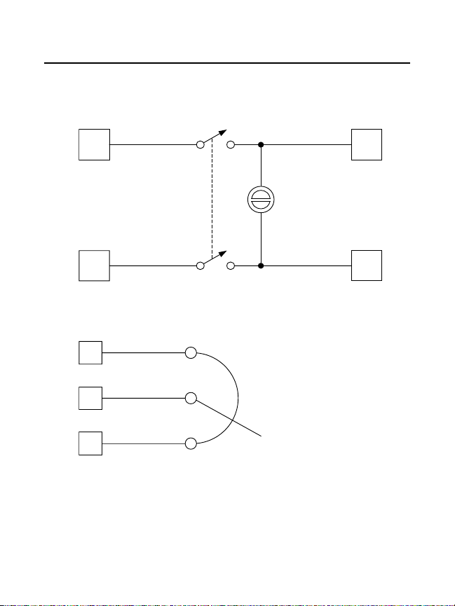
Figure 10. Inhibit Plug with Run/Coast to Zero Speed Switch . . . . . . . . . . . . . . .22
Figure 11. Run/Decelerate to Minimum Speed Switch . . . . . . . . . . . . . . . . . . . . .23
Figure 12. Dynamic Brake Connection . . . . . . . . . . . . . . . . . . . . . . . . . . . . . . . . .24
Figure 13. C4XL3025 CURR LIMIT and IR COMP Settings . . . . . . . . . . . . . . . . .31
Figure 14. C4XL3200A TORQ. LIMIT and IR COMP Settings . . . . . . . . . . . . . . .31
Figure 15. C4XL3025 MAX SPEED Settings for
Low Voltage DC Motors . . . . . . . . . . . . . . . . . . . . . . . . . . . . . . . . . . . .32
Figure 16. C4XL3200A MAX SPD Settings for
Low Voltage DC Motors . . . . . . . . . . . . . . . . . . . . . . . . . . . . . . . . . . . .33
Figure 17. Leader-Follower Application . . . . . . . . . . . . . . . . . . . . . . . . . . . . . . . . .34
Figure 18. Single Speed Potentiometer Control of Multiple Drives . . . . . . . . . . . .35
Figure 19. C4XL3025 Series Block Diagram . . . . . . . . . . . . . . . . . . . . . . . . . . . .40
Figure 20. C4XL3200A Block Diagram . . . . . . . . . . . . . . . . . . . . . . . . . . . . . . . . .41

Specifications
Model Number C4XL3025
Type: Cased
NEMA Rating NEMA 4X
AC Line Voltage 115 VAC/230 VAC, ±10%, 50/60 Hz, single phase
Line Fuse Rating 8 A
Horsepower Range @ 130 VDC Output 1/20–1/3 HP
Horsepower Range @ 240 VDC Output 1/8–1/2 HP
Maximum Armature Voltage Range @ 115 VAC Input 50–130 VDC
Maximum Armature Voltage Range @ 230 VAC Input 50–240 VDC
Minimum Speed Adjustment Range @ 115 VAC Input 0–65 VDC
Minimum Speed Adjustment Range @ 230 VAC Input 0–65 VDC
Maximum Armature Current 3 ADC
Field Voltage @ 115 VAC Input 50 VDC/100 VDC
Field Voltage @ 230 VAC Input 100 VDC/200 VDC
Maximum Field Current 1 ADC
Form Factor 1.05
Acceleration Time Range (no load)
for 0–130 VDC Armature Voltage Range 1–10 seconds
for 0–240 VDC Armature Voltage Range 1–19 seconds
Deceleration Time Range (no load)
for 0–130 VDC Armature Voltage Range 3–9 seconds
for 0–240 VDC Armature Voltage Range 4–19 seconds
Analog Input Voltage Range (signal must be isolated; S1 to S2)
for 0–130 VDC Armature Voltage 0–2.7 VDC
for 0–240 VDC Armature Voltage 0–5.0 VDC
1

2
Specifications
Speed Adjustment Potentiometer 10K ohms
Approximate Input Impedance (from S1 to S2) 100K ohms
Speed Regulation (at base speed) 1%
Weight 4.4 lb
Ambient Operating Temperature Range 10ºC–40ºC
Vibration 0.5g max (0 – 50 Hz)
0.1g max (above 50 Hz)

Specifications
Model Number C4XL3200A
Type Cased
NEMA Rating NEMA 4X
AC Line Voltage 115 VAC/230 VAC, ±10%, 50/60 Hz, single phase
Line Fuse Rating 15 A
Horsepower Range @ 130 VDC Output 1/4–1 HP
Horsepower Range @ 240 VDC Output 1/2–2 HP
Maximum Armature Voltage Range @ 115 VAC Input 50–130 VDC
Maximum Armature Voltage Range @ 230 VAC Input 50–240 VDC
Minimum Speed Adjustment Range @ 115 VAC Input 0–120 VDC
Minimum Speed Adjustment Range @ 230 VAC Input 0–120 VDC
Maximum Armature Current 10 ADC
Field Voltage @ 115 VAC Input 50 VDC/100 VDC
Field Voltage @ 230 VAC Input 100 VDC/200 VDC
Maximum Field Current 1 ADC
Form Factor 1.05
Acceleration Time Range (no load)
for 0–130 VDC Armature Voltage Range 1–10 seconds
for 0–240 VDC Armature Voltage Range 1–15 seconds
Deceleration Time Range (no load)
for 0–130 VDC Armature Voltage Range 1–10 seconds
for 0–240 VDC Armature Voltage Range 1–19 seconds
Analog Input Voltage Range (signal must be isolated; S1 to S2)
for 0–130 VDC Armature Voltage 0–2.7 VDC
for 0–240 VDC Armature Voltage 0–5.0 VDC
Speed Adjustment Potentiometer 10K ohms
3

4
Specifications
Approximate Input Impedance (from S1 to S2) 50K ohms
Speed Regulation (at base speed) 1%
Weight 7.4 lb
Ambient Operating Temperature Range 10ºC–40ºC
Vibration 0.5g max (0 – 50 Hz)
0.1g max (above 50 Hz)
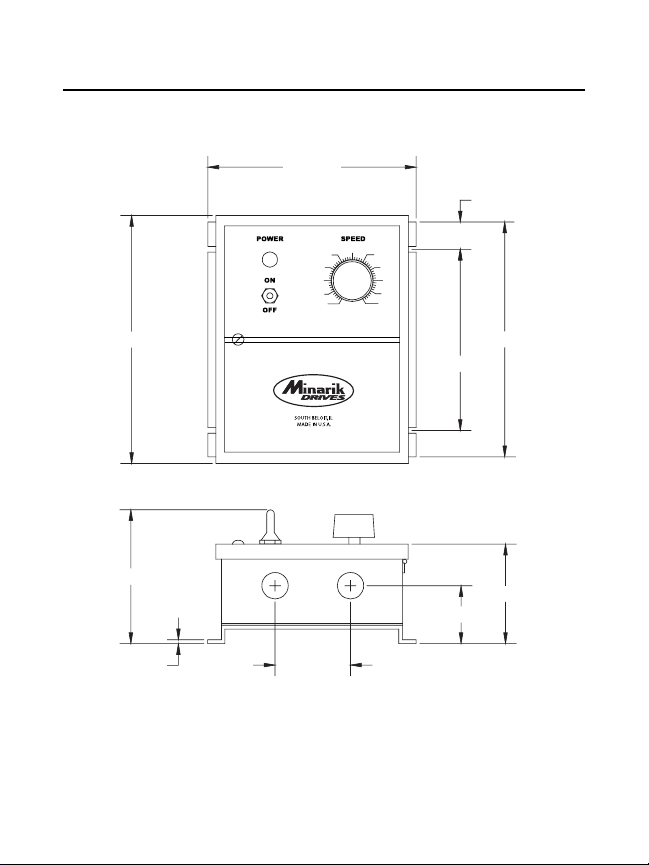
Dimensions
6.90 [175]
40
30 70
20 80
10 90
0 100
5
0.91 [23]
50
60
8.20 [207]
4.43 [112]
0.13 [3]
7.78 [197]
6.00 [152]
FOUR MOUNTING SLOTS 0.19 [5] WIDE
3.29 [83]
1.92 [49]
2.50 [63]
TWO 0.88 [22] KNOCKOUTS
ALL DIMENSIONS IN INCHES [MILLIMETERS]
Figure 1. C4XL3025 Dimensions
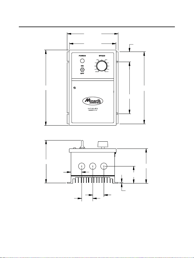
6 Dimensions
6.90 [175]
6.30 [159]
40 60
30 70
20 80
10 90
0 100
1.37 [35]
50
10.22 [259]
5.79 [146]
1.45 [37]
7.00 [177]
FOUR MOUNTING SLOTS 0.19 [5] WIDE
2.31 [58]
0.12 [3]
1.50 [38]
1.50 [38]
THREE 0.88 [22] KNOCKOUTS
ALL DIMENSIONS IN INCHES [ MILLIMETERS]
Figure 2. C4XL3200A Dimensions
9.75 [247]
4.69 [119]

Installation
Mounting
Nema 4X cased drives come with 0.88 inch (22 mm) conduit
knockout holes at the bottom of the case. The units may be
vertically wall mounted using the four 0.19 inch (5 mm) slotted
holes on the attached heat sink. For motor loads less than 5 ADC,
the drive may be bench mounted horizontally, or operated without
mounting.
1. Install the mounting screws through the drive’s four mounting
slots.
2. For access to the terminal strip, turn the slotted screw on the
front cover counterclockwise until it is free from the case. The
right side of the cover is hinged to the case. Pull the slotted
screw to open the case.
3. Carefully remove the 0.88 inch (22 mm) conduit knockouts by
tapping them into the case and twisting them off with pliers.
7
4. Install conduit hardware through the knockout holes. Connect
external wiring to the terminal block.

8 Installation
5. Grasp the slotted screw and tilt the front cover back into place.
Avoid pinching any wires between the front cover and the case.
6. Turn the slotted screw clockwise until tight to secure the front
cover.
7. Set the POWER switch to the OFF position before applying the
AC line voltage.
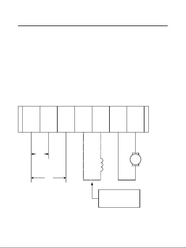
Connections
Minarik drives supply motor voltage to terminals A1 and A2 (A1 is
positive with respect to A2). It is assumed throughout this manual
that the driven motor will rotate clockwise (CW) while looking at the
output shaft protruding from the front of the motor. If the opposite is
desired, simply reverse the wiring of A1 and A2 with each other.
TB501
L1 115 230 F1 F2 A2 A1
9Installation
115
AC Line Voltage
115 or 230 VAC
230
Figure 3. C4XL3025 Connections
Motor
+
Field Output Shunt wound motors only.
See Field Output section for
connections.
Armature
Output
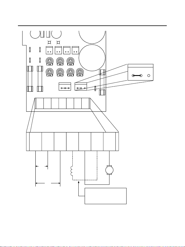
10 Installation
POWER ON
LIMIT
CURR
PS4
PS2
PS1
FAST-ACTING
IL501
IL502
SO501
115230L1
CURR
TORQ. LIMIT
S1
TB501
SO504S0503
+15
S2 S3
IR COMP
ACCELDECELMIN SPD
A1F+
INHIBIT
JOG
FUSE ONLY FU501
PS3
FAST-ACTING
FUSE ONLY FU502
SO502
POWER
MAX SPD
TB501
L1 230 115 F+ A1 F- A2
C505
FAST-ACTING
FUSE ONLY FU502
A2
JOGSPDSPD
IN
A2F-
SPD SPD JOG
IN
SPD and SPD IN are
prewired for speed adjust
poteniometer control.
To control speed with JOG
trimmer potentiometer,
connect SPD IN to JOG.
Motor will not turn if there is
no connection to SPD IN.
230
AC Line Voltage
115 or 230 VAC
115
Field Output Shunt wound motors only.
See Field Output section for
connections.
Figure 4. C4XL3200A Connections
Armature
Motor
Output
Power
Switch
11Installation
PS1
PS3
S1
S2
S3
black
white
violet
brown
grey
CW
black/white
Power
Light
white/black
10K ohm
Speed Adjust
Potentiometer
PS2
PS4
Figure 5. Prewired Connections for Models C4XL3025 and
C4XL3200A
 Loading...